A Homebrew UHF SWR Bridge
A Homebrew UHF SWR Bridge
A Homebrew UHF SWR Bridge

You also want an ePaper? Increase the reach of your titles
YUMPU automatically turns print PDFs into web optimized ePapers that Google loves.
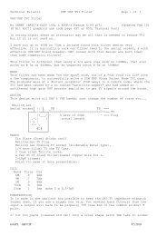
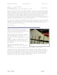
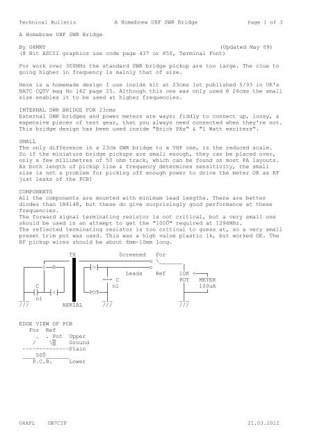
Technical Bulletin A <strong>Homebrew</strong> <strong>UHF</strong> <strong>SWR</strong> <strong>Bridge</strong> Page 1 of 3A <strong>Homebrew</strong> <strong>UHF</strong> <strong>SWR</strong> <strong>Bridge</strong>By G8MNY (Updated May 09)(8 Bit ASCII graphics use code page 437 or 850, Terminal Font)For work over 300MHz the standard <strong>SWR</strong> bridge pickup are too large. The clue togoing higher in frequency is mainly that of size.Here is a homemade design I use inside kit at 23cms 1st published 5/93 in UK'sBATC CQTV mag No 162 page 25. Although this one was only used @ 24cms the smallsize enables it to be used at higher frequencies.INTERNAL <strong>SWR</strong> BRIDGE FOR 23cmsExternal <strong>SWR</strong> bridges and power meters are ways; fiddly to connect up, lossy, &expensive pieces of test gear, that you always need connected when they're not.This bridge design has been used inside "Brick PAs" & "1 Watt exciters".SMALLThe only difference in a 23cm <strong>SWR</strong> bridge to a VHF one, is the reduced scale.So if the miniature bridge pickups are small enough, they can be placed over,only a few millimetres of 50 ohm track, which can be found on most PA layouts.As both length of pickup line & frequency determines sensitivity, the smallsize is not a problem for picking off enough power to drive the meter OK as RFjust leaks of the PCB!COMPONENTSAll the components are mounted with minimum lead lengths. There are betterdiodes than 1N4148, but these do give surprisingly good performance at thesefrequencies.The forward signal terminating resistor is not critical, but a very small oneshould be used in an attempt to get the "100Û" required at 1296MHz.The reflected terminating resistor is too critical to guess at, so a very smallpreset trim pot was used. This was a high value plastic 1k, but worked OK. TheRF pickup wires should be about 6mm-10mm long.TX Screened For┌─────── █ ─────────────────────o \_______┌─────)──R──┐ █ ┌─┤>├──┬────────────o││ │ │ █ │ │ Leads Ref 10K
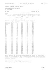
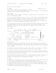
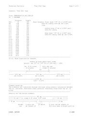
Technical Bulletin A <strong>Homebrew</strong> <strong>UHF</strong> <strong>SWR</strong> <strong>Bridge</strong> Page 2 of 3CALIBRATION1/ Adjust the calibration pot to give no meter reading on a GOOD LOAD.2/ With reduced output (PA run on 10V) & NO load connected, adjust pickupdistances so that forward & reflected give the same reading.3/ As 2 but with a FULL SHORT connected, adjust distances for best compromisein forward & reflected readings.4/ Recheck 2.5/ With full power set the sensitivity pot for FSD.Meter scaleDeflection % 100 80 72 50 33 20 8 0<strong>SWR</strong> 1: Inf 9 6 3 2 1.5 1.2 1Loss dB Inf 4.4 3 1.3 0.5 0.2 .035 0HOW IT WORKSThe principle to these pick up loop <strong>SWR</strong> bridges is really the same as the HFtype with RF transfomers etc. except the sensitivity is proportional tofrequency. e.g. 2x frequency = 2x deflection or 4x power! (Bird meters of thistype use lossy dielectric inbetween to flatten the frequency response a bit)If we look at how a pickup loops sees both the voltage & current components.█ ┌─┤>├─┬─ █ ┌─┤>├─┬─ █ ┌─┤>├─┬─█ │ │ ¨ █ ¦ │ █ │ │█ │ === = █ ¦L === + █┤├┤ ===█ │ │ █ ¦¨ │ █ C│ │█ └──R──┤ █ └─────┤ █ └──R──┤█ _│_ █ _│_ █ _│_/// /// ///BOTH CURRENT ONLY VOLTAGE ONLYIf we don't have an R the voltage across the loop L is proportional to current& drives the detector & is current (power) direction sensitive.If we have just stray capacitance C & no parallel pick up loop, some of thefeeder voltage appears across the R & the detector sees that & as it is justvoltage it is not power direction sensitive.Now as the L was not terminated the voltage will be leading by about 90° & thesame is true for the C feeding the R & it leads by approx 90°. When the 2 RFsignals are added in series they either add up to double for power going up orcancel for power going down on transmission line.Cancelling (<strong>SWR</strong> 1:1) only occurs if the R value has the same voltage & phase asthe pick up loop for an ideal load. The R can be switched on some <strong>SWR</strong> bridgesfor the values needed for 75Û systems.Note that its is not a "true power meter", as "Voltage + Current" is not thesame as "Voltage x Current", & that can lead to calibration errors on anythingother than "perfect loads".See also my Tech bul on "Meter Damping & Speed Up".Why don't U send an interesting bul?73 De John, G8MNY @ GB7CIPG4APL GB7CIP 21.03.2012
Technical Bulletin A <strong>Homebrew</strong> <strong>UHF</strong> <strong>SWR</strong> <strong>Bridge</strong> Page 3 of 3G4APL GB7CIP 21.03.2012