Installation Manual: DVU Series Dump Valves; models ... - FW Murphy
Installation Manual: DVU Series Dump Valves; models ... - FW Murphy
Installation Manual: DVU Series Dump Valves; models ... - FW Murphy

You also want an ePaper? Increase the reach of your titles
YUMPU automatically turns print PDFs into web optimized ePapers that Google loves.
<strong>Installation</strong> and Operation <strong>Manual</strong> for<br />
<strong>DVU</strong> <strong>Series</strong> <strong>Dump</strong> <strong>Valves</strong><br />
Models: <strong>DVU</strong>150, <strong>DVU</strong>175, <strong>DVU</strong>2105, <strong>DVU</strong>2115 and <strong>DVU</strong>2120<br />
<strong>Installation</strong> 00-02-0483 page 1 of 4<br />
00-02-0483<br />
Revised 03-06<br />
Section 15<br />
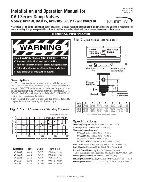
Please read the following information before installing. A visual inspection of this product for damage during shipping is recommended<br />
before mounting. It is your responsibility to have a qualified person install this unit and make sure it conforms to local codes.<br />
WARNING<br />
BEFORE BEGINNING INSTALLATION OF THIS MURPHY PRODUCT<br />
✔ Disconnect all electrical power to the machine.<br />
✔ Make sure the machine cannot operate during installation.<br />
✔ Follow all safety warnings of the machine manufacturer.<br />
✔ Read and follow all installation instructions.<br />
Description<br />
The <strong>DVU</strong> <strong>Series</strong> <strong>models</strong> are pneumatically controlled dump valves.<br />
The valves open and close automatically by pneumatic control from a<br />
<strong>Murphy</strong> L1200NDVOR or similar level controller and dump valve operator.<br />
Diaphragm actuated, the <strong>DVU</strong> series dump valves operate at 30–70 psi<br />
(207–483 kPa) [2.07–4.83 bar] and up to 2000 psi (13.8 MPa) [138 bar]<br />
vessel pressure (depending on the model).<br />
A key benefit of this design is a hex union that provides the ability<br />
to replace the seat without removing the valve from piping.<br />
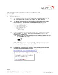
Fig. 1 Control Pressure vs. Working Pressure<br />
Control Pressure (PSIG)<br />
70<br />
60<br />
50<br />
40<br />
30<br />
20<br />
10<br />
0<br />
<strong>DVU</strong>2105<br />
500<br />
<strong>DVU</strong>2115<br />
GENERAL INFORMATION<br />
1000 1500 2000<br />
Vessel Pressure (PSIG)<br />
Minimum Actuation Pressure<br />
<strong>DVU</strong>2120<br />
Model Inlet Outlet Trim Size<br />
<strong>DVU</strong>2120 2 NPT 1 NPT 0.436 in. (11 mm)<br />
<strong>DVU</strong>2115 2 NPT 1 NPT 0.576 in. (15 mm)<br />
<strong>DVU</strong>2105 2 NPT 1 NPT 0.859 in. (22 mm)<br />
<strong>DVU</strong>175 1 NPT 3/4 NPT 0.359 in. (9 mm)<br />
<strong>DVU</strong>150 1 NPT 1/2 NPT 0.359 in. (9 mm)<br />
<strong>DVU</strong>150/175<br />
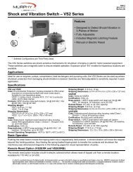
Fig. 2 Dimensions (all <strong>models</strong>)<br />
Pressure<br />
Inlet Port<br />
1/8 in.-27 NPT<br />
F Drain<br />
Connection<br />
E<br />
Plug Seal<br />
A<br />
<strong>Manual</strong> Valve<br />
Operator<br />
Vent<br />
Weep Hole Valve Open/Closed<br />
Union<br />
Indicator Button<br />
C<br />
D<br />
B<br />
(dimension shown G for reference only)<br />
Model A B C D E F G<br />
<strong>DVU</strong>2120 7.50 (191) 8.0 (203) 2.75 (70) 1.0 (25) 2-11.5 NPT 1-11.5 NPT 1.03<br />
<strong>DVU</strong>2115 7.50 (191) 8.0 (203) 2.75 (70) 1.0 (25) 2-11.5 NPT 1-11.5 NPT 1.03<br />
<strong>DVU</strong>2105 7.50 (191) 8.0 (203) 2.75 (70) 1.0 (25) 2-11.5 NPT 1-11.5 NPT 1.03<br />
<strong>DVU</strong>175 7.50 (191) 6.75 (171) 2.06 (52) 1.0 (25) 1-11.5 NPT 3/4”-14 NPT 1.03<br />
<strong>DVU</strong>150 7.50 (191) 6.75 (171) 2.06 (52) 1.0 (25) 1-11.5 NPT 1/2”-14 NPT 1.03<br />
NOTE: Dimensions are in inches and (millimeters)<br />
Specifications<br />
Operating Temperature: -30 to 250°F (-34.4 to +121°C)<br />
Valve Operating Pressure: Refer to chart, Fig 1.<br />
Maximum Process Pressure:<br />
<strong>DVU</strong>2120: 2000 psi (13.8 MPa) [138 bar].<br />
<strong>DVU</strong>2115: 1500 psi (10.3 MPa) [103 bar].<br />
<strong>DVU</strong>2105: 500 psi (3.44 MPa) [34 bar].<br />
<strong>DVU</strong>150 and <strong>DVU</strong>175: 1800 psi (12.4 MPa) [124 bar].<br />
Flow Characteristics: See chart, page 4 (<strong>DVU</strong>150/175 <strong>models</strong> only).<br />
Body Material: Electroless Nickel Plated 12L14 Carbon Steel<br />
Internal Wetted Parts: Plug Seal: 90 Durometer Urethane.<br />
Other: 303 stainless steel; Electroless Nickel Plated 12L14 Carbon Steel<br />
Shipping Weights: <strong>DVU</strong>150 and <strong>DVU</strong>175: 9 lbs. (4 kg.).<br />
Shipping Weights: <strong>DVU</strong>2105, <strong>DVU</strong>2115 and <strong>DVU</strong>2120: 14 lbs. (6.4 kg.).<br />
Shipping Dimensions: 7-1/2 x 7-1/2 x 10-3/4 in. (191 x 191 x 274 mm.).
Basic Operation<br />
As condensate rises in the scrubber, the float<br />
on the L1200NDVOR rises and trips its pneumatic<br />
valve. The valve opens allowing pressure<br />
to enter the dump valve pilot chamber.<br />
Once the pressure enters the pilot chamber it<br />
forces the diaphragm and valve stem forward<br />
thus opening the valve seat (valve open/closed<br />
indicator button pops out) and releasing condensate<br />
through the valve stem and out the<br />
drain. As the condensate level drops, the<br />
L1200NDVOR pneumatic valve closes to shut<br />
off the pressure to the dump valve causing it to<br />
close.<br />
If for any reason the condensate continues to<br />
rise beyond normal dump levels, model L1200<br />
operates the alarm and/or shuts down the<br />
equipment.<br />
The L1200NDVOR Filter/Regulator and the<br />
MURPHYGAGE ® help keep the control pressure<br />
clean and dry. They also allow the operator<br />
to adjust pressure to recommended levels.<br />
NOTE: Always use clean, dry,<br />
instrument quality gas.<br />
<strong>DVU</strong> <strong>Series</strong> <strong>Installation</strong><br />
TYPICAL INSTALLATION ON GAS COMPRESSORS<br />
Fig. 3<br />
Scrubber/Separators<br />
CAUTION: ALWAYS USE “NON-SPARKING TOOLS”<br />
WHEN GAS IS KNOWN TO BE PRESENT.<br />
The following describes the “Direct Mounting” method to the<br />
tank wall.<br />
1. Install the valve so the drain connection is on the bottom. Use<br />
pipe thread sealant on all the connections.<br />
2. Be sure the unit is screwed tight and does not leak.<br />
3. Install the piping for the pneumatic input signal into the<br />
1/8 NPT threaded connection of the pressure inlet port (on<br />
top of the diaphragm housing of the <strong>DVU</strong>).<br />
6. Install a union between the <strong>DVU</strong> drain connection and the<br />
condensate out line. Use pipe thread sealant on all the connections.<br />
The <strong>Murphy</strong> Gas Compressor Scrubber Level System (SLS)<br />
The system provides for liquid<br />
control in gas scrubber<br />
applications, by dumping liquids<br />
to drain and protecting<br />
compressors with a high liquid<br />
level switch. Wetted metal<br />
parts are made to survive<br />
constant use in corrosive<br />
environments.<br />
See Bulletin: SLS-04005B for<br />
more details.<br />
Filter/Regulator &<br />
MURPHYGAGE ®<br />
“Instrument<br />
Quality Air/Gas<br />
Supply”<br />
Pneumatic Level Control<br />
Float actuated level snap-acting switch<br />
controls pneumatic pressure to open<br />
and close dump valve.<br />
L1200NDVOR: <strong>Dump</strong> Valve Operator,<br />
pressure regulator, and pressure indicating<br />
MURPHYGAGE. ®<br />
DUMP VALVE INSTALLATION<br />
Fig. 4<br />
Typical<br />
<strong>Dump</strong> Valve<br />
<strong>Installation</strong><br />
<strong>Installation</strong> 00-02-0483 page 2 of 4<br />
Vessel Wall<br />
High Level Shutdown Switch<br />
Stainless steel float actuated level switches to alarm<br />
and/or shutdown the equipment.<br />
L1200: 2” NPT pipe connection; Rated 2000 psi<br />
(13.7MPa) [137bar]; Class I, Division 1. SPDT<br />
snap-switch standard. DPDT Optional.<br />
All Stainless Steel available.<br />
Pneumatic <strong>Dump</strong><br />
<strong>Valves</strong> See <strong>DVU</strong>-01069B<br />
for more details.<br />
Two piece union design with manual valve operator<br />
allows soft plug and hard seat to be replaced without<br />
disassembling outlet piping or scrubber pipe<br />
connection. Diaphragm actuated valves operate on<br />
30-70 psi (207-483 kPa; 2-5 bar).<br />
Upper Assembly<br />
(removable)<br />
Valve<br />
Union<br />
Drain<br />
Connection<br />
Union<br />
Pneumatic<br />
Input Signal<br />
Maintenance<br />
Bolt<br />
Valve Indicator<br />
Weep Hole<br />
2-Way (<strong>Manual</strong> Drain)<br />
Shutoff Valve<br />
Control<br />
Panel<br />
Condensate Out
CAUTION: THE INSTALLATION AND REPAIR PROCEDURES SHOULD<br />
ONLY BE PERFORMED BY TRAINED, QUALIFIED, AND EXPERIENCED<br />
PERSONNEL. THE TRAINING, QUALIFICATION AND EXPERIENCE<br />
REQUIRED IS FOR WORK AROUND PRESSURE VESSELS, NATURAL GAS, POSSI-<br />
BLY SOUR GAS, OR ANY SUBSTANCE TO BE FOUND IN THE VESSEL. EXTREME<br />
CARE MUST BE TAKEN TO INSURE ANY RESIDUAL OR FULL PRESSURE IS<br />
RELIEVED FROM ALL PARTS OF THE SYSTEM TO BE SERVICED.<br />
Suggested Tools (Sizes listed are wrench openings.<br />
Adjustable crescent wrenches, socket and/or end wrench, pipe wrenches,<br />
flat edge screwdriver with 1/4” blade width, can also be used .)<br />
Model Valve Body Union Nut Plug Seal Hex Stem Nut<br />
<strong>DVU</strong>2120 3” 3” 7/8” 1/2”<br />
<strong>DVU</strong>2115 3” 3” 1” 1/2”<br />
<strong>DVU</strong>2105 3” 3” 1-1/4” 1/2”<br />
<strong>DVU</strong>150/<strong>DVU</strong>175 2-1/4” 2-1/4” 3/4” 3/8”<br />
Replacing the Plug and Seat<br />
1. Close the pressure block valves (suction & discharge valves) on the inlet<br />
and outlet of the skid. Lock them closed if possible.<br />
2. Open the blowdown valve to remove pressure from the unit. Lock the<br />
blowdown valve open if possible.<br />
3. After taking all possible precautions to insure there is no pressure in the<br />
vessel. (If the condensate line is pressurized, it must also be blocked and<br />
locked.) Open the manual drain valve so it bleeds into the vessel so it<br />
can also be bled down. Disconnect the pneumatic input signal connection<br />
after insuring it also has been de-pressurized.<br />
4. Using a back-up wrench on the valve body, with a quick "breaking"<br />
action loosen the union nut on the valve. There is a "weep" hole in the<br />
nut. If at any time while loosening and taking off the nut pressure is<br />
escaping through the "weep" hole, immediately stop loosening the nut.<br />
Retighten the nut and check the preceding procedures to ensure the pressure<br />
is bled off the vessel. Never remove the assembly if pressure is<br />
coming through the weep hole. See Figure 4 on page 2.<br />
5. With the upper assembly removed from the vessel the plug and/or seat can<br />
be replaced. Loosen the 9/16” jam nut on the maintenance bolt on top of<br />
the diaphragm cover. Spin the nut up against the head of the bolt. Tighten<br />
the bolt to extend the shaft and plug. DO NOT OVERTIGHTEN.<br />
Fig. 5<br />
Washer(s)*<br />
Stem<br />
Nut<br />
O-Ring<br />
Plug<br />
Seat<br />
Stem<br />
Crush Washer Seal<br />
Stem<br />
Packing<br />
Seat butts into here<br />
O-Ring Seals<br />
Against Outlet<br />
*Number of washers varies depending on the model from 1 to 3.<br />
Seal Washer Maintenance<br />
Pressure Inlet<br />
Bolt<br />
Diaphragm<br />
1/2" Nut<br />
Fig. 6<br />
Backup<br />
Plate<br />
1-1/8" or<br />
1" round nut<br />
Stem<br />
Spring<br />
REPAIR PROCEDURE<br />
Diaphragm<br />
Housing<br />
Diaphragm<br />
Assembly<br />
<strong>Installation</strong> 00-02-0483 page 3 of 4<br />
6. Using a back-up wrench on the plug, remove the stem nut on the shaft<br />
under the plug. Once the stem nut is broken loose, the 9/16” head maintenance<br />
bolt and top assembly will keep the stem from turning. The plug<br />
turns freely on the stem once loose. The plug and seat can now be<br />
removed. All soft seals should be replaced. Refer to kit part numbers<br />
under service parts on page 4.<br />
Replacing the Diaphragm<br />
6A. If the diaphragm is to be replaced, all preceding steps have to be<br />
done. Additionally, do the following:<br />
6B. Loosen the 9/16” head maintenance bolt, allowing the diaphragm<br />
spring to relax, and the stem to retract. Make alignment marks on<br />
the top and bottom halves of the diaphragm assembly for alignment<br />
during re-assembly.<br />
6C. Remove the 8, 7/16" bolts/nuts holding the diaphragm housing<br />
together.<br />
6D. Using a straight edge screwdriver, gently separate the 2 halves of<br />
the diaphragm housing, and remove the top, or outside portion.<br />
6E. Lift the diaphragm and support plates far enough for the 1-1/8" hex<br />
or 1” round nut on the bottom of the diaphragm assembly to be<br />
accessible to a wrench and not have the spring interfere. If it is<br />
desired to replace the packing, pull the stem all the way out. The<br />
packing can be easily removed using a small screwdriver to pry the<br />
packing out. The new packing can be simply pressed in, making<br />
sure the orientation of the packing installed is the same as the orientation<br />
of the packing removed. The packing is wider toward the<br />
plug end. You will have to use the seat to hold the packing in place<br />
when re-inserting the stem.<br />
6F. With the 1-1/8" hex or 1” round nut held by a wrench, use a<br />
wrench to loosen and remove the 1/2" nut on top of the diaphragm.<br />
The diaphragm can now be removed and replaced.<br />
6G. With the new diaphragm in place and the 1/2" nut tightened, place<br />
the assembly, diaphragm down on a clean, smooth sturdy surface.<br />
6H. Have the seat, plug, washers and stem nut handy (if any of these<br />
parts are to be replaced, use the old parts for this procedure). Press<br />
down evenly and smoothly on the bottom of the diaphragm assembly<br />
to cause stem to come up. Place the seat and plug in place.<br />
Then push the bottom of the diaphragm assembly down far enough<br />
to install the washers and stem nut on the stem. Tighten the stem<br />
nut enough to hold against the diaphragm spring.<br />
6J. Align the diaphragm holes to the bolt holes (bottom half of the<br />
housing). Install the upper diaphragm housing using the alignment<br />
marks from step 6B. Install the 8, 7/16" bolts and nuts. Tighten the<br />
bolts evenly going from one bolt then 180° around to the next bolt,<br />
then either 120°or 240° around to the next bolt and so forth until<br />
all 8 bolts are evenly tight.<br />
6K. Using the 9/16” head maintenance bolt, tighten, pushing the stem<br />
out until the 9/16"bolt stops – DO NOT OVERTIGHTEN.<br />
6L. Remove the stem nut holding the plug. (If old parts were used, prepare<br />
to install the new parts now.)<br />
7. Install the seat and plug. Place the O-ring on the stem, followed by the<br />
washer and stem nut.<br />
8. Tighten the stem nut. Loosen the 9/16” head maintenance bolt by at least one<br />
turn past the point where it is no longer in contact with the stem. Tighten the<br />
9/16" jam nut holding the 9/16” head maintenance bolt.<br />
9. Replace the crush washer and the O-ring hidden by the union nut.<br />
NOTE: If pressure or fluid comes out the weep hole of the union nut,<br />
either the O-ring under the union nut is leaking, or the packing could be<br />
leaking through the internal weep hole above that O-ring.<br />
10. The assembly is ready to be re-installed. Check for relative position of<br />
the pneumatic input signal connections before tightening the union nut.
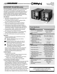
Fig. 7<br />
Pressure (psid)<br />
250<br />
200<br />
150<br />
100<br />
50<br />
0<br />
0<br />
Part No. Description<br />
<strong>DVU</strong>2120<br />
55-00-0237 Seal Kit (includes plug)<br />
55-00-0236 Diaphragm Kit<br />
<strong>DVU</strong>2115<br />
55-00-0241 Seal Kit (includes plug)<br />
55-00-0240 Diaphragm Kit<br />
<strong>DVU</strong>2105<br />
55-00-0245 Seal Kit (includes plug)<br />
55-00-0244 Diaphragm Kit<br />
<strong>DVU</strong>175<br />
55-00-0230 Seal Kit (includes plug)<br />
55-00-0231 Diaphragm Kit<br />
5<br />
PRESSURE VS. FLOW CHART<br />
Pressure vs. Flow for <strong>DVU</strong>150 and <strong>DVU</strong>175 <strong>models</strong> only<br />
<strong>DVU</strong>150<br />
55-00-0230 Seal Kit (includes plug)<br />
55-00-0231 Diaphragm Kit<br />
Typical Seal Kit includes: Nut, Washer (1 to 3), “O” Ring, Plug and<br />
Seal, Seat, Crush Washer.<br />
www.fwmurphy.com<br />
918.317.4100 Email: sales@fwmurphy.com<br />
10 15 20 25 30 35 40 45<br />
Flow (gpm)<br />
SERVICE PARTS<br />
<strong>Installation</strong> 00-02-0483 page 4 of 4<br />
Typical Diaphragm Repair Kit includes:<br />
Diaphragm; Diaphragm Washer (upper), Diaphragm Nut, Diaphragm Plate<br />
(1 or 2 pcs.), Packing, “O” Ring, Stem, Seal Washer for Maintenance Bolt.<br />
The <strong>DVU</strong> <strong>Series</strong> Valve is included in the<br />
following Scrubber Levels Systems.<br />
(Includes L1200, L1200NDVOR, and <strong>DVU</strong> valve)<br />
SLS2120: Includes <strong>DVU</strong>2120 valve<br />
SLS2115: Includes <strong>DVU</strong>2115 valve<br />
SLS2105: Includes <strong>DVU</strong>2105 valve<br />
SLS175: Includes <strong>DVU</strong>175 valve<br />
SLS150: Includes <strong>DVU</strong>150 valve<br />
-LR: Less Regulator option<br />
Warranty<br />
A limited warranty on materials and workmanship is given with this <strong>FW</strong><br />
<strong>Murphy</strong> product. A copy of the warranty may be viewed or printed by going<br />
to www.fwmurphy.com/support/warranty.htm<br />
MURPHY, the <strong>Murphy</strong> logo are registered and/or common law trademarks of <strong>Murphy</strong> Industries, Inc. This document,<br />
including textual matter and illustrations, is copyright protected by <strong>Murphy</strong> Industries, Inc., with all rights reserved.<br />
(c) 2006 <strong>Murphy</strong> Industries, Inc. Other third party product or trade names referenced herein are the property of<br />
their respective owners and are used for identification purposes only.