

Introduction: Voice Activated Relay Switch (Arduino)


Hello Everyone!
In this project, I will show you how to implement voice commands for your Arduino projects.
Using voice commands, I will show you how to control a relay switch module.
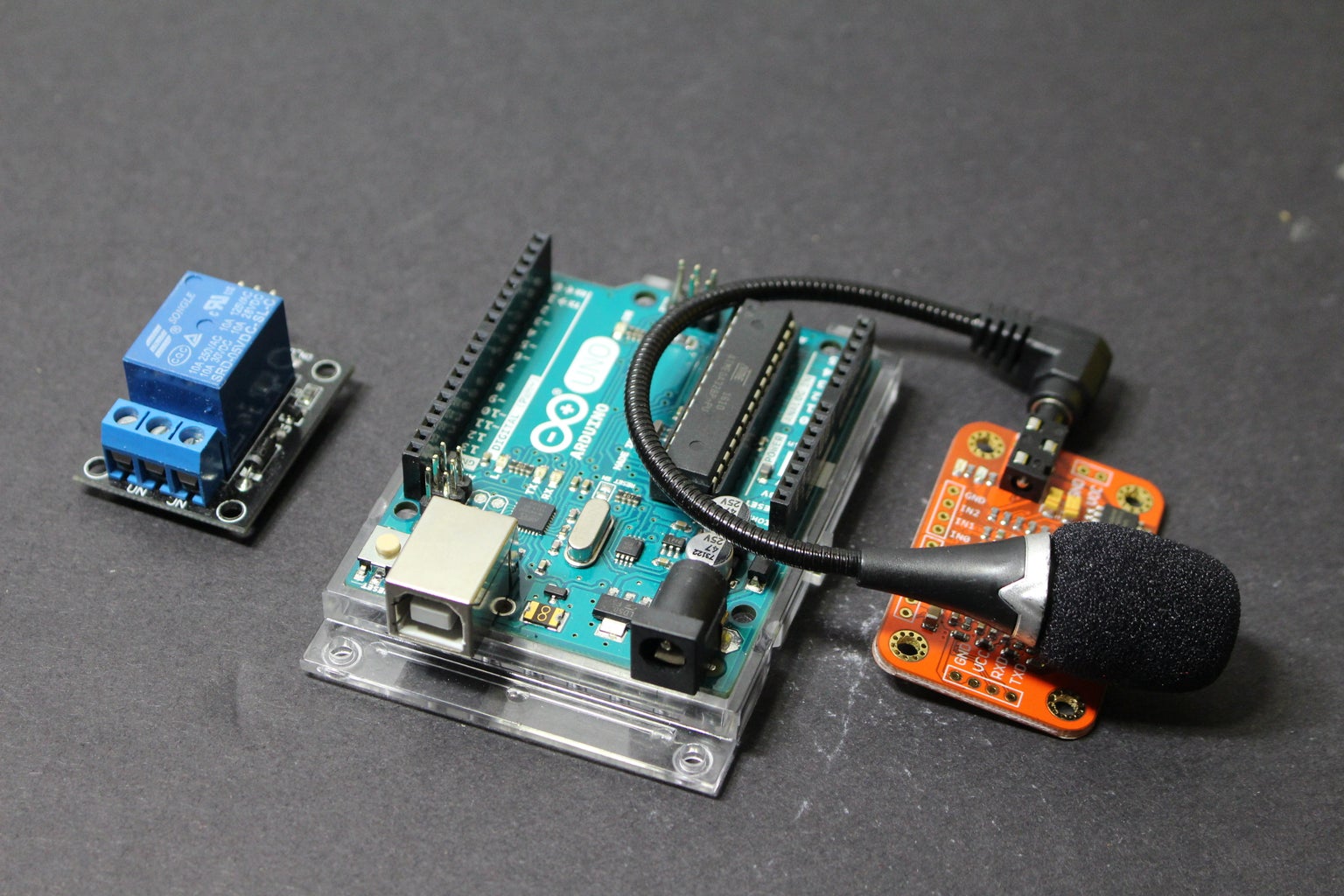
Step 1: Components

Step 2: Wiring (Voice Recognition Module)

Before we start with the coding process, we need to wire the Arduino to the Voice Recognition Module.
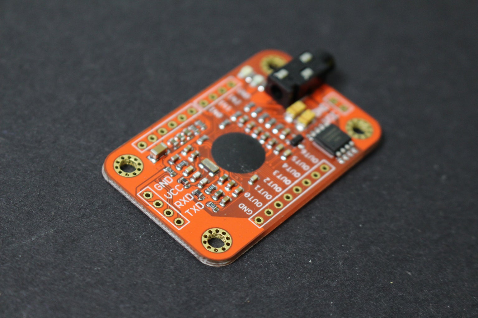
There are 4 pins on the Voice Recognition Module.
GND is connected to the ground connection (Arduino)
VCC is connected to the 5v connection (Arduino)
RXD is programmed to Arduino’s digital pin #3 by default
TXD is programmed to Arduino’s digital pin #2 by default
Step 3: Wiring (Relay Module)

On the relay module, there are 3 pins
Negative pin connects to the ground pin on the Arduino
Positive pin connects to the 5v pin on the Arduino
S pin will be programmed to the 13th pin on the Arduino
Additionally, in order to test the relay switch, I will be using the 11th pin on the Arduino as a digital output
This pin will have constant power and the relay switch will use voice command to direct electricity to multiple LEDs
For this project, I used a breadboard and jumper wires to make all the connections.
As long as all the can be made properly, you may use your own method for wiring your circuit.
Step 4: Coding - Voice Training

In order to start coding, you’ll need to download the Voice Recognition V3 library from this PDF.
I also had to update Arduino IDE to the latest version to prevent uploading errors.
Once you have installed everything, you need to go through FILE – EXAMPLES – VOICE RECOGNITION V3 MASTER and click on VR_SAMPLE_TRAIN
The training portion helps us define certain voice commands in order to control the Arduino’s digital pins.
By controlling the Arduino’s digital pins, we can control the relay module that can be used to control high voltage devices.
The code for voice training is already developed and does not need to be changed in any way.
After uploading the code to the Arduino board, you need to open the Serial Monitor at 115200 baud rate
In order to train voice commands, you’ll need to type the word “settings” and hit enter or click send.
Next, you’ll need to define the voice command using this format: sigtrain 0 On
sigtrain is a list of programmable voice commands that ranges from 0-6
In this command, the word On represents what I will be saying into the microphone
Once you hit send or enter, the serial monitor will ask you to “speak now”.
During this time you will say “On” as clearly as possible into the microphone.
The serial monitor will ask you to repeat the phrase until the training is complete.
Once the first phrase was successfully trained, I trained sigtrain 1 as Off
Overall, if I say “On”, the Voice Recognition Module will recognise it as sigtrain 0.
If I say off, the Voice Recognition Module will recognise it as sigtrain 1
For the last step of the training mode, you’ll need to type load 0 1 and hit enter or send.
This will allow you to use the serial monitor to monitor the accuracy of the voice commands.
Attachments

Step 5: Coding - Voice Activated Relay Switch

After completing the training portion, I opened the example named vr_sample_control_led
I also slightly modified the code in order to work with the relay module.
I changed led pin into 11 and I defined int relay as pin 13
In this code, 0 is defined as the phrase “On” and 1 is defined as the “Off” phrase from training.
Inside void setup, the relay and led are set as an output pins.
Inside void loop, the led pin is constantly set as High output pin to test the relay.
This line of code is optional because the relay module has a built in led to indicate a closed circuit.
There is an if statement that turns on the relay switch through pin#13 if the ON phrase is detected.
If the off phrase was detected, pin 13 will be set to low, turning off the relay switch.
Once the modified led control code has been uploaded to the Arduino, I unplugged the usb and used a 9v battery to power the Arduino.
Once the Arduino reset, I spoke into the microphone and the relay module turned on
Once I said off, the relay turned off as expected.
Attachments

Step 6: Finished


Inside the relay switch, there is a common contact that normally connects to the NC contact.
Once the relay is energized, the common contact connects with the NO contact.
Even if the common contact is connected using high voltage, the relay switch can still be controlled using the Arduino.
In this project, pin 11 provides 3.3volts of energy through the common contact while the 13th pin controls the relay module.
Ultimately, the phrases “on” and “off” controls the 13th pin which controls the relay module.
If you found this project helpful, feel free to make your own voice activated project.
The code for the Voice Recognition Module was developed by various authors and it can be found in the Voice Recognition Module library
file: vr_sample_train.ino
author: JiapengLi
file: vr_sample_control_led.ino
author: JiapengLi
If you liked this project, please considering subscribing to the youtube channel for more content.

Runner Up in the
Voice Activated Challenge

Participated in the
Epilog Challenge 9

Participated in the
Remote Control Contest 2017

Participated in the
Arduino Contest 2017


