WO1997024983A2 - Mapping catheter - Google Patents
Mapping catheter Download PDFInfo
- Publication number
- WO1997024983A2 WO1997024983A2 PCT/IL1997/000009 IL9700009W WO9724983A2 WO 1997024983 A2 WO1997024983 A2 WO 1997024983A2 IL 9700009 W IL9700009 W IL 9700009W WO 9724983 A2 WO9724983 A2 WO 9724983A2
- Authority
- WO
- WIPO (PCT)
- Prior art keywords
- accordance
- catheter
- sensors
- distal end
- heart
- Prior art date
Links
Classifications
-
- A—HUMAN NECESSITIES
- A61—MEDICAL OR VETERINARY SCIENCE; HYGIENE
- A61N—ELECTROTHERAPY; MAGNETOTHERAPY; RADIATION THERAPY; ULTRASOUND THERAPY
- A61N1/00—Electrotherapy; Circuits therefor
- A61N1/18—Applying electric currents by contact electrodes
- A61N1/32—Applying electric currents by contact electrodes alternating or intermittent currents
- A61N1/36—Applying electric currents by contact electrodes alternating or intermittent currents for stimulation
- A61N1/362—Heart stimulators
- A61N1/365—Heart stimulators controlled by a physiological parameter, e.g. heart potential
- A61N1/36514—Heart stimulators controlled by a physiological parameter, e.g. heart potential controlled by a physiological quantity other than heart potential, e.g. blood pressure
- A61N1/36564—Heart stimulators controlled by a physiological parameter, e.g. heart potential controlled by a physiological quantity other than heart potential, e.g. blood pressure controlled by blood pressure
-
- A—HUMAN NECESSITIES
- A61—MEDICAL OR VETERINARY SCIENCE; HYGIENE
- A61B—DIAGNOSIS; SURGERY; IDENTIFICATION
- A61B17/00—Surgical instruments, devices or methods, e.g. tourniquets
- A61B17/22—Implements for squeezing-off ulcers or the like on the inside of inner organs of the body; Implements for scraping-out cavities of body organs, e.g. bones; Calculus removers; Calculus smashing apparatus; Apparatus for removing obstructions in blood vessels, not otherwise provided for
- A61B17/22004—Implements for squeezing-off ulcers or the like on the inside of inner organs of the body; Implements for scraping-out cavities of body organs, e.g. bones; Calculus removers; Calculus smashing apparatus; Apparatus for removing obstructions in blood vessels, not otherwise provided for using mechanical vibrations, e.g. ultrasonic shock waves
- A61B17/22012—Implements for squeezing-off ulcers or the like on the inside of inner organs of the body; Implements for scraping-out cavities of body organs, e.g. bones; Calculus removers; Calculus smashing apparatus; Apparatus for removing obstructions in blood vessels, not otherwise provided for using mechanical vibrations, e.g. ultrasonic shock waves in direct contact with, or very close to, the obstruction or concrement
-
- A—HUMAN NECESSITIES
- A61—MEDICAL OR VETERINARY SCIENCE; HYGIENE
- A61B—DIAGNOSIS; SURGERY; IDENTIFICATION
- A61B17/00—Surgical instruments, devices or methods, e.g. tourniquets
- A61B17/34—Trocars; Puncturing needles
- A61B17/3403—Needle locating or guiding means
-
- A—HUMAN NECESSITIES
- A61—MEDICAL OR VETERINARY SCIENCE; HYGIENE
- A61B—DIAGNOSIS; SURGERY; IDENTIFICATION
- A61B18/00—Surgical instruments, devices or methods for transferring non-mechanical forms of energy to or from the body
- A61B18/18—Surgical instruments, devices or methods for transferring non-mechanical forms of energy to or from the body by applying electromagnetic radiation, e.g. microwaves
- A61B18/20—Surgical instruments, devices or methods for transferring non-mechanical forms of energy to or from the body by applying electromagnetic radiation, e.g. microwaves using laser
-
- A—HUMAN NECESSITIES
- A61—MEDICAL OR VETERINARY SCIENCE; HYGIENE
- A61B—DIAGNOSIS; SURGERY; IDENTIFICATION
- A61B34/00—Computer-aided surgery; Manipulators or robots specially adapted for use in surgery
- A61B34/20—Surgical navigation systems; Devices for tracking or guiding surgical instruments, e.g. for frameless stereotaxis
-
- A—HUMAN NECESSITIES
- A61—MEDICAL OR VETERINARY SCIENCE; HYGIENE
- A61B—DIAGNOSIS; SURGERY; IDENTIFICATION
- A61B5/00—Measuring for diagnostic purposes; Identification of persons
- A61B5/02—Detecting, measuring or recording pulse, heart rate, blood pressure or blood flow; Combined pulse/heart-rate/blood pressure determination; Evaluating a cardiovascular condition not otherwise provided for, e.g. using combinations of techniques provided for in this group with electrocardiography or electroauscultation; Heart catheters for measuring blood pressure
- A61B5/021—Measuring pressure in heart or blood vessels
- A61B5/0215—Measuring pressure in heart or blood vessels by means inserted into the body
-
- A—HUMAN NECESSITIES
- A61—MEDICAL OR VETERINARY SCIENCE; HYGIENE
- A61B—DIAGNOSIS; SURGERY; IDENTIFICATION
- A61B5/00—Measuring for diagnostic purposes; Identification of persons
- A61B5/02—Detecting, measuring or recording pulse, heart rate, blood pressure or blood flow; Combined pulse/heart-rate/blood pressure determination; Evaluating a cardiovascular condition not otherwise provided for, e.g. using combinations of techniques provided for in this group with electrocardiography or electroauscultation; Heart catheters for measuring blood pressure
- A61B5/026—Measuring blood flow
- A61B5/029—Measuring or recording blood output from the heart, e.g. minute volume
-
- A—HUMAN NECESSITIES
- A61—MEDICAL OR VETERINARY SCIENCE; HYGIENE
- A61B—DIAGNOSIS; SURGERY; IDENTIFICATION
- A61B5/00—Measuring for diagnostic purposes; Identification of persons
- A61B5/06—Devices, other than using radiation, for detecting or locating foreign bodies ; determining position of probes within or on the body of the patient
-
- A—HUMAN NECESSITIES
- A61—MEDICAL OR VETERINARY SCIENCE; HYGIENE
- A61B—DIAGNOSIS; SURGERY; IDENTIFICATION
- A61B5/00—Measuring for diagnostic purposes; Identification of persons
- A61B5/145—Measuring characteristics of blood in vivo, e.g. gas concentration, pH value; Measuring characteristics of body fluids or tissues, e.g. interstitial fluid, cerebral tissue
-
- A—HUMAN NECESSITIES
- A61—MEDICAL OR VETERINARY SCIENCE; HYGIENE
- A61B—DIAGNOSIS; SURGERY; IDENTIFICATION
- A61B5/00—Measuring for diagnostic purposes; Identification of persons
- A61B5/24—Detecting, measuring or recording bioelectric or biomagnetic signals of the body or parts thereof
- A61B5/25—Bioelectric electrodes therefor
- A61B5/279—Bioelectric electrodes therefor specially adapted for particular uses
- A61B5/28—Bioelectric electrodes therefor specially adapted for particular uses for electrocardiography [ECG]
- A61B5/283—Invasive
- A61B5/287—Holders for multiple electrodes, e.g. electrode catheters for electrophysiological study [EPS]
-
- A—HUMAN NECESSITIES
- A61—MEDICAL OR VETERINARY SCIENCE; HYGIENE
- A61B—DIAGNOSIS; SURGERY; IDENTIFICATION
- A61B5/00—Measuring for diagnostic purposes; Identification of persons
- A61B5/68—Arrangements of detecting, measuring or recording means, e.g. sensors, in relation to patient
- A61B5/6801—Arrangements of detecting, measuring or recording means, e.g. sensors, in relation to patient specially adapted to be attached to or worn on the body surface
- A61B5/6843—Monitoring or controlling sensor contact pressure
-
- A—HUMAN NECESSITIES
- A61—MEDICAL OR VETERINARY SCIENCE; HYGIENE
- A61B—DIAGNOSIS; SURGERY; IDENTIFICATION
- A61B5/00—Measuring for diagnostic purposes; Identification of persons
- A61B5/68—Arrangements of detecting, measuring or recording means, e.g. sensors, in relation to patient
- A61B5/6846—Arrangements of detecting, measuring or recording means, e.g. sensors, in relation to patient specially adapted to be brought in contact with an internal body part, i.e. invasive
- A61B5/6847—Arrangements of detecting, measuring or recording means, e.g. sensors, in relation to patient specially adapted to be brought in contact with an internal body part, i.e. invasive mounted on an invasive device
- A61B5/6852—Catheters
- A61B5/6853—Catheters with a balloon
-
- A—HUMAN NECESSITIES
- A61—MEDICAL OR VETERINARY SCIENCE; HYGIENE
- A61B—DIAGNOSIS; SURGERY; IDENTIFICATION
- A61B5/00—Measuring for diagnostic purposes; Identification of persons
- A61B5/68—Arrangements of detecting, measuring or recording means, e.g. sensors, in relation to patient
- A61B5/6846—Arrangements of detecting, measuring or recording means, e.g. sensors, in relation to patient specially adapted to be brought in contact with an internal body part, i.e. invasive
- A61B5/6847—Arrangements of detecting, measuring or recording means, e.g. sensors, in relation to patient specially adapted to be brought in contact with an internal body part, i.e. invasive mounted on an invasive device
- A61B5/6852—Catheters
- A61B5/6856—Catheters with a distal loop
-
- A—HUMAN NECESSITIES
- A61—MEDICAL OR VETERINARY SCIENCE; HYGIENE
- A61B—DIAGNOSIS; SURGERY; IDENTIFICATION
- A61B5/00—Measuring for diagnostic purposes; Identification of persons
- A61B5/68—Arrangements of detecting, measuring or recording means, e.g. sensors, in relation to patient
- A61B5/6846—Arrangements of detecting, measuring or recording means, e.g. sensors, in relation to patient specially adapted to be brought in contact with an internal body part, i.e. invasive
- A61B5/6847—Arrangements of detecting, measuring or recording means, e.g. sensors, in relation to patient specially adapted to be brought in contact with an internal body part, i.e. invasive mounted on an invasive device
- A61B5/6852—Catheters
- A61B5/6858—Catheters with a distal basket, e.g. expandable basket
-
- A—HUMAN NECESSITIES
- A61—MEDICAL OR VETERINARY SCIENCE; HYGIENE
- A61B—DIAGNOSIS; SURGERY; IDENTIFICATION
- A61B5/00—Measuring for diagnostic purposes; Identification of persons
- A61B5/68—Arrangements of detecting, measuring or recording means, e.g. sensors, in relation to patient
- A61B5/6846—Arrangements of detecting, measuring or recording means, e.g. sensors, in relation to patient specially adapted to be brought in contact with an internal body part, i.e. invasive
- A61B5/6847—Arrangements of detecting, measuring or recording means, e.g. sensors, in relation to patient specially adapted to be brought in contact with an internal body part, i.e. invasive mounted on an invasive device
- A61B5/6852—Catheters
- A61B5/6859—Catheters with multiple distal splines
-
- A—HUMAN NECESSITIES
- A61—MEDICAL OR VETERINARY SCIENCE; HYGIENE
- A61B—DIAGNOSIS; SURGERY; IDENTIFICATION
- A61B8/00—Diagnosis using ultrasonic, sonic or infrasonic waves
- A61B8/08—Detecting organic movements or changes, e.g. tumours, cysts, swellings
- A61B8/0833—Detecting organic movements or changes, e.g. tumours, cysts, swellings involving detecting or locating foreign bodies or organic structures
- A61B8/0841—Detecting organic movements or changes, e.g. tumours, cysts, swellings involving detecting or locating foreign bodies or organic structures for locating instruments
-
- A—HUMAN NECESSITIES
- A61—MEDICAL OR VETERINARY SCIENCE; HYGIENE
- A61N—ELECTROTHERAPY; MAGNETOTHERAPY; RADIATION THERAPY; ULTRASOUND THERAPY
- A61N1/00—Electrotherapy; Circuits therefor
- A61N1/18—Applying electric currents by contact electrodes
- A61N1/32—Applying electric currents by contact electrodes alternating or intermittent currents
- A61N1/36—Applying electric currents by contact electrodes alternating or intermittent currents for stimulation
- A61N1/362—Heart stimulators
- A61N1/3627—Heart stimulators for treating a mechanical deficiency of the heart, e.g. congestive heart failure or cardiomyopathy
-
- A—HUMAN NECESSITIES
- A61—MEDICAL OR VETERINARY SCIENCE; HYGIENE
- A61N—ELECTROTHERAPY; MAGNETOTHERAPY; RADIATION THERAPY; ULTRASOUND THERAPY
- A61N1/00—Electrotherapy; Circuits therefor
- A61N1/40—Applying electric fields by inductive or capacitive coupling ; Applying radio-frequency signals
-
- A—HUMAN NECESSITIES
- A61—MEDICAL OR VETERINARY SCIENCE; HYGIENE
- A61N—ELECTROTHERAPY; MAGNETOTHERAPY; RADIATION THERAPY; ULTRASOUND THERAPY
- A61N7/00—Ultrasound therapy
- A61N7/02—Localised ultrasound hyperthermia
-
- A—HUMAN NECESSITIES
- A61—MEDICAL OR VETERINARY SCIENCE; HYGIENE
- A61B—DIAGNOSIS; SURGERY; IDENTIFICATION
- A61B10/00—Other methods or instruments for diagnosis, e.g. instruments for taking a cell sample, for biopsy, for vaccination diagnosis; Sex determination; Ovulation-period determination; Throat striking implements
- A61B10/02—Instruments for taking cell samples or for biopsy
-
- A—HUMAN NECESSITIES
- A61—MEDICAL OR VETERINARY SCIENCE; HYGIENE
- A61B—DIAGNOSIS; SURGERY; IDENTIFICATION
- A61B17/00—Surgical instruments, devices or methods, e.g. tourniquets
- A61B2017/00017—Electrical control of surgical instruments
- A61B2017/00022—Sensing or detecting at the treatment site
- A61B2017/00039—Electric or electromagnetic phenomena other than conductivity, e.g. capacity, inductivity, Hall effect
- A61B2017/00044—Sensing electrocardiography, i.e. ECG
- A61B2017/00048—Spectral analysis
- A61B2017/00053—Mapping
-
- A—HUMAN NECESSITIES
- A61—MEDICAL OR VETERINARY SCIENCE; HYGIENE
- A61B—DIAGNOSIS; SURGERY; IDENTIFICATION
- A61B17/00—Surgical instruments, devices or methods, e.g. tourniquets
- A61B17/00234—Surgical instruments, devices or methods, e.g. tourniquets for minimally invasive surgery
- A61B2017/00238—Type of minimally invasive operation
- A61B2017/00243—Type of minimally invasive operation cardiac
- A61B2017/00247—Making holes in the wall of the heart, e.g. laser Myocardial revascularization
-
- A—HUMAN NECESSITIES
- A61—MEDICAL OR VETERINARY SCIENCE; HYGIENE
- A61B—DIAGNOSIS; SURGERY; IDENTIFICATION
- A61B17/00—Surgical instruments, devices or methods, e.g. tourniquets
- A61B2017/00681—Aspects not otherwise provided for
- A61B2017/00694—Aspects not otherwise provided for with means correcting for movement of or for synchronisation with the body
-
- A—HUMAN NECESSITIES
- A61—MEDICAL OR VETERINARY SCIENCE; HYGIENE
- A61B—DIAGNOSIS; SURGERY; IDENTIFICATION
- A61B17/00—Surgical instruments, devices or methods, e.g. tourniquets
- A61B17/22—Implements for squeezing-off ulcers or the like on the inside of inner organs of the body; Implements for scraping-out cavities of body organs, e.g. bones; Calculus removers; Calculus smashing apparatus; Apparatus for removing obstructions in blood vessels, not otherwise provided for
- A61B17/22004—Implements for squeezing-off ulcers or the like on the inside of inner organs of the body; Implements for scraping-out cavities of body organs, e.g. bones; Calculus removers; Calculus smashing apparatus; Apparatus for removing obstructions in blood vessels, not otherwise provided for using mechanical vibrations, e.g. ultrasonic shock waves
- A61B2017/22005—Effects, e.g. on tissue
- A61B2017/22007—Cavitation or pseudocavitation, i.e. creation of gas bubbles generating a secondary shock wave when collapsing
- A61B2017/22008—Cavitation or pseudocavitation, i.e. creation of gas bubbles generating a secondary shock wave when collapsing used or promoted
-
- A—HUMAN NECESSITIES
- A61—MEDICAL OR VETERINARY SCIENCE; HYGIENE
- A61B—DIAGNOSIS; SURGERY; IDENTIFICATION
- A61B18/00—Surgical instruments, devices or methods for transferring non-mechanical forms of energy to or from the body
- A61B2018/00053—Mechanical features of the instrument of device
- A61B2018/00273—Anchoring means for temporary attachment of a device to tissue
- A61B2018/00291—Anchoring means for temporary attachment of a device to tissue using suction
-
- A—HUMAN NECESSITIES
- A61—MEDICAL OR VETERINARY SCIENCE; HYGIENE
- A61B—DIAGNOSIS; SURGERY; IDENTIFICATION
- A61B18/00—Surgical instruments, devices or methods for transferring non-mechanical forms of energy to or from the body
- A61B2018/00315—Surgical instruments, devices or methods for transferring non-mechanical forms of energy to or from the body for treatment of particular body parts
- A61B2018/00345—Vascular system
- A61B2018/00351—Heart
- A61B2018/00392—Transmyocardial revascularisation
-
- A—HUMAN NECESSITIES
- A61—MEDICAL OR VETERINARY SCIENCE; HYGIENE
- A61B—DIAGNOSIS; SURGERY; IDENTIFICATION
- A61B34/00—Computer-aided surgery; Manipulators or robots specially adapted for use in surgery
- A61B34/20—Surgical navigation systems; Devices for tracking or guiding surgical instruments, e.g. for frameless stereotaxis
- A61B2034/2046—Tracking techniques
- A61B2034/2051—Electromagnetic tracking systems
-
- A—HUMAN NECESSITIES
- A61—MEDICAL OR VETERINARY SCIENCE; HYGIENE
- A61B—DIAGNOSIS; SURGERY; IDENTIFICATION
- A61B90/00—Instruments, implements or accessories specially adapted for surgery or diagnosis and not covered by any of the groups A61B1/00 - A61B50/00, e.g. for luxation treatment or for protecting wound edges
- A61B90/39—Markers, e.g. radio-opaque or breast lesions markers
- A61B2090/3954—Markers, e.g. radio-opaque or breast lesions markers magnetic, e.g. NMR or MRI
- A61B2090/3958—Markers, e.g. radio-opaque or breast lesions markers magnetic, e.g. NMR or MRI emitting a signal
-
- A—HUMAN NECESSITIES
- A61—MEDICAL OR VETERINARY SCIENCE; HYGIENE
- A61B—DIAGNOSIS; SURGERY; IDENTIFICATION
- A61B2562/00—Details of sensors; Constructional details of sensor housings or probes; Accessories for sensors
- A61B2562/04—Arrangements of multiple sensors of the same type
- A61B2562/043—Arrangements of multiple sensors of the same type in a linear array
-
- A—HUMAN NECESSITIES
- A61—MEDICAL OR VETERINARY SCIENCE; HYGIENE
- A61B—DIAGNOSIS; SURGERY; IDENTIFICATION
- A61B34/00—Computer-aided surgery; Manipulators or robots specially adapted for use in surgery
- A61B34/25—User interfaces for surgical systems
-
- A—HUMAN NECESSITIES
- A61—MEDICAL OR VETERINARY SCIENCE; HYGIENE
- A61B—DIAGNOSIS; SURGERY; IDENTIFICATION
- A61B5/00—Measuring for diagnostic purposes; Identification of persons
- A61B5/06—Devices, other than using radiation, for detecting or locating foreign bodies ; determining position of probes within or on the body of the patient
- A61B5/061—Determining position of a probe within the body employing means separate from the probe, e.g. sensing internal probe position employing impedance electrodes on the surface of the body
- A61B5/062—Determining position of a probe within the body employing means separate from the probe, e.g. sensing internal probe position employing impedance electrodes on the surface of the body using magnetic field
-
- A—HUMAN NECESSITIES
- A61—MEDICAL OR VETERINARY SCIENCE; HYGIENE
- A61M—DEVICES FOR INTRODUCING MEDIA INTO, OR ONTO, THE BODY; DEVICES FOR TRANSDUCING BODY MEDIA OR FOR TAKING MEDIA FROM THE BODY; DEVICES FOR PRODUCING OR ENDING SLEEP OR STUPOR
- A61M25/00—Catheters; Hollow probes
- A61M25/01—Introducing, guiding, advancing, emplacing or holding catheters
- A61M25/0105—Steering means as part of the catheter or advancing means; Markers for positioning
- A61M2025/0166—Sensors, electrodes or the like for guiding the catheter to a target zone, e.g. image guided or magnetically guided
-
- A—HUMAN NECESSITIES
- A61—MEDICAL OR VETERINARY SCIENCE; HYGIENE
- A61N—ELECTROTHERAPY; MAGNETOTHERAPY; RADIATION THERAPY; ULTRASOUND THERAPY
- A61N1/00—Electrotherapy; Circuits therefor
- A61N1/18—Applying electric currents by contact electrodes
- A61N1/32—Applying electric currents by contact electrodes alternating or intermittent currents
- A61N1/36—Applying electric currents by contact electrodes alternating or intermittent currents for stimulation
- A61N1/362—Heart stimulators
- A61N1/365—Heart stimulators controlled by a physiological parameter, e.g. heart potential
- A61N1/368—Heart stimulators controlled by a physiological parameter, e.g. heart potential comprising more than one electrode co-operating with different heart regions
-
- A—HUMAN NECESSITIES
- A61—MEDICAL OR VETERINARY SCIENCE; HYGIENE
- A61N—ELECTROTHERAPY; MAGNETOTHERAPY; RADIATION THERAPY; ULTRASOUND THERAPY
- A61N5/00—Radiation therapy
- A61N5/10—X-ray therapy; Gamma-ray therapy; Particle-irradiation therapy
- A61N5/1048—Monitoring, verifying, controlling systems and methods
- A61N5/1064—Monitoring, verifying, controlling systems and methods for adjusting radiation treatment in response to monitoring
Definitions
- the present invention relates generally to medical electrophysiology systems, and specifically to invasive medical probes that may be used to map the elect ⁇ cal activity of the heart.
- Mapping the activation front and conduction fields aids the physician in identifying and diagnosing abnormalities, such as vent ⁇ cular and at ⁇ al tachycardia and ventricular and atrial fibrillation, that result from areas of impaired elect ⁇ cal propagation in the heart tissue
- Localized defects in the heart's conduction of activation signals may be identified by observing phenomena such as multiple activation fronts, abnormal concentrations of activation vectors, or changes in the velocity vector or deviation of the vector from normal values.
- Mapping of the electrical activation time in the heart muscle requires that the location of the sensor within the heart be known at the time of each measurement. Such mapping may be performed using a single movable electrode sensor inside the heart, which sensor measures activation time relative to a fixed extemal reference electrode. This technique, however, gives maps of low resolution and relatively poor accuracy, limited by the accuracy of determination of the position of the electrode at the time of each measurement. The natural movement of the heart makes it very difficult to maintain an accurate reading of the position of the moving electrode from beat to beat. Mapping of electrical activation time using a single electrode is, furthermore, a lengthy procedure, which must generally be performed under fluoroscopic imaging, thereby exposing the patient to undesirable ionizing radiation. Further, in an arrhythmic heart, activation times at a single location may change between consecutive beats.
- U.S. patent 5,487,391 to Panescu, for example, describes a multiple electrode probe for deployment inside the heart. Signals received from the multiple electrodes are used for denvmg the propagation velocity of depola ⁇ zation events. This patent makes no provision, however, for independently determining the positions of the electrodes relative to an external or heart-fixed frame of reference, and the velocity is derived relative to the probe, rather than to the heart itself.
- Each electrode senses local electrogram signals generated in the endocardium in a small area near the side of the catheter that it faces. Differences in the activation times in the signals sensed by the pairs of electrodes are used to estimate the direction of the activation vector in the vicinity of the catheter, so as to guide the operator in positioning the ablator.
- PCT publication WO/95/ 10226 desc ⁇ bes a catheter that includes a ⁇ ng at its distal end, designed to bear against the circumference of a valve of the heart.
- the ⁇ ng comp ⁇ ses electrodes, which measure elect ⁇ cal activity in the valve tissue. When abnormal elect ⁇ cal activity is detected in the valve tissue adjacent to one of the electrodes, an electrical current is applied through the electrode so as to ablate the tissue at the site of the abnormal activity.
- the invention provides no means for determination of the position of the ⁇ ng and electrodes, however, other than methods of imaging known m the art, and is therefore not useful for mapping electrical activity, nor is it useful in areas of the heart other than the valves.
- Patent 5,555,883 to Avitall describes a catheter with a loop shaped mapping and ablation system. There is no provision, in this patent, for determining the position of individual electrodes relative to the heart surface being mapped ablated.
- the sensors are fixed to a catheter, and the locations of the sensors are measured by determining the position of a device in the catheter that generates position and orientation information.
- a further object of the present invention is to provide a method and a device for rapidly and accurately measuring local electrical propagation vectors in the heart muscle, in order to locate sites of abnormal electrical propagation, for purposes of subsequent diagnosis and therapy.
- a plurality of electrodes are attached. to a structure at the distal end of a catheter.
- One or more devices for generating position information are placed in proximity to the electrodes, so that the positions of all the electrodes can be determined in relation to an extemal frame of reference or relative to the heart.
- the position information and signals measured by the electrodes are used to determine the direction and magnitude of the electrical activation vector at the location of the structure at the distal end of the catheter.
- the structure at the distal end of the catheter comprises at least three non-collinear electrodes, so that the direction of the electrical activation vector in the plane defined by the electrodes may be fully determined.
- the electrodes are attached to a substantially rigid ring at the distal end of a catheter.
- a device that generates position information is coupled to the ring, so that the position and rotational orientation of the ring may be determined, thus determining the locations of all the electrodes.
- the geometrical shape and angular orientation of the ring are known relative to the catheter. If the locations of the electrodes relative to the catheter are substantially predetermined, the positions of all the electrodes may be determined from a determined position and orientation of the catheter tip. Further, in this case, it is sufficient to determine the location of the tip and only the rotational coordinate of the catheter tip around its axis.
- the ring at the distal end of the catheter is placed in contact with the endocardium, and the electrical propagation vector is measured at the location of the ring.
- the distal end of the catheter may then be repeatedly repositioned to other locations on the endocardium, so as to generate a map of the propagation vector field or to locate an area of abnormality.
- substantially rigid as applied to the ring at the distal end of the catheter, is taken to mean that during successive measurements of electrophysiological signals by the electrodes, the shape of the ring and its angular orientation relative to the long axis of the catheter remain fixed in a known, predetermined relation.
- the location of each of the electrodes on the ring relative to a coordinate information device is fixed and known, and thus the locations of all the electrodes relative to an extemal reference frame may be determined using the location and orientation information provided by the coordinate information device.
- the electrodes are allowed to move relative to each other, as a result of myocardial contraction.
- the substantially rigid ring maintains its shape during measurements, for purposes of insertion and removal of the catheter the ring may be straightened or flattened, so as to pass easily through narrow channels, such as blood vessels, or through a lumen of the catheter.
- the substantially rigid ring is formed of a resilient, super-elastic material, such as NiTi.
- the ring is compressed inside a narrow sleeve adjacent to the distal end of the catheter. After insertion of the catheter, the ring is ejected from the sleeve and assumes its predetermined shape and position.
- the substantially rigid ring is made from a flat, ribbon-like section of resilient material.
- the distal end of the catheter, with which the ring is in contact after it has been ejected from the sleeve, is likewise flat and includes a slot necessary for ejection of the ring.
- the ring is formed of a hollow section of resilient, superelastic material, which is rigidly coupled to the distal end of the catheter at a known angular orientation.
- the ring is straightened by insertion of a stylette into the lumen of the hollow section. After insertion of the catheter into the heart, the stylette is withdrawn, and the ring reassumes its predetermined shape and orientation.
- the ring at the distal end of the catheter is formed of a hollow section of flexible material, which is straightened for insertion or removal of the catheter from the body by insertion of a straight stylette into the lumen of the hollow section.
- a second stylette formed of substantially rigid, resilient material and including a curved portion at its distal end, is inserted.
- the curved distal portion of the stylette is straightened, and the relative stiffness of the catheter causes the stylette to remain straight.
- the distal tip of this section engages a socket in the side of the catheter. Fluoroscopy or other methods of imaging known in the art may be used to observe the ring at the distal end of the catheter and verify that the distal tip of the distal section has engaged the socket, so as to ensure that the ring has assumed its desired shape and orientation prior to beginning electrophysiological measurements.
- the distal tip of the distal end section of the catheter comprises a first electrical contact
- the socket in the side of the catheter comprises a second electrical contact.
- the first electrical contact is brought into proximity with the second electrical contact.
- the mutual proximity of the contacts is measured electrically using methods known in the art, so as to verify that the distal tip has engaged the socket.
- the structure to which the electrodes are attached at the distal end of the catheter may comprise a ring of any desired cross-sectional profile, or the structure may be formed in a shape of non-uniform profile.
- the structure comprises rigid sections, to which the electrodes are attached, and flexible, resilient sections between the rigid sections. The flexible, resilient sections allow the structure to be easily collapsed for passage through the blood vessels, and then cause the structure to resume its desired shape for making measurements when released inside a chamber of the heart.
- the structure to which the electrodes are attached at the distal end of the catheter is polygonal, most preferably triangular with sharp vertices.
- sharp vertices of the polygonal structure When the sharp vertices of the polygonal structure are brought into contact with the endocardium, they will typically lodge in small crevices in the heart tissue, thus preventing the structure from moving during measurement, despite the natural motion of the heart.
- the electrodes are preferably at the vertices.
- the structure in which the electrodes are placed at the distal end of the catheter comprises multiple arms, wherein electrodes are fixed to the arms.
- the arms are held parallel and adjacent to the long central axis of the catheter. Once inside the heart, the arms spread apart, away from the long axis of the catheter at predetermined, known angles.
- each arm is formed of at least two sections of substantially rigid material, connected together by a resilient joint.
- the arms are joined at their proximal ends to the distal end of the catheter.
- a draw-wire passes through-a lumen in the catheter and is attached at its distal end to the distal ends of the arms, which are joined together.
- the resilient joints tend to hold the arms straight and parallel to the long central axis of the catheter.
- the draw-wire is pulled back until the joints are completely flexed, and the distal ends of the arms are brought into close proximity with the proximal ends thereof, so that the arms protrude laterally out from the long central axis of the catheter.
- the draw- wire is released, and the resilient joints straighten to their original shapes.
- substantially rigid arms having electrodes adjacent to their distal ends, are contained inside a lumen of the catheter during insertion of the catheter into the heart.
- the distal ends of the arms are ejected through small radial openings, spaced around the axis of the catheter.
- the resilience of the arms causes them to spread apart radially away from the long central axis of the catheter and axially, distal to the distal end of the catheter.
- the structure at the distal end of the catheter is a balloon or another inflatable structure, to which electrodes are fixed. After the catheter has been inserted into the heart, the structure is inflated and assumes a predetermined, known shape and orientation relative to the distal end of the catheter.
- the device that generates position information comprises a plurality of coils, as disclosed in PCT patent application number PCT/US95/01 103, filed January 24, 1995, which is assigned to the assignee of the present application and whose disclosure is incorporated herein by reference.
- This device continuously generates six-dimensional position and orientation information regarding the catheter tip.
- This system uses a plurality of non-concentric coils adjacent to a locatable site in the catheter, for example near its distal end. These coils generate signals in response to externally applied magnetic fields, which allow for the computation of six location and orientation coordinates, so that the location and orientation of the catheter in the heart are known without the need for simultaneous imaging, by fluoroscopy or ultrasound, for example.
- This device generates position information relative to a reference frame defined by field generator coils.
- a Carto system available from Biosense LTD., Tirat Hacarmel, Israel, is used for determining the position of a catheter.
- inventions of the present invention comprise one or more devices for generating three-dimensional location information, as described, for example, in U.S. patent 5,391,199, to Ben-Haim, and PCT patent application PCT US94/08352, which are assigned to the assignee of the present application and whose disclosures are incorporated herein by reference.
- One or more devices for generating location information are placed in the catheter or in the structure containing the electrodes, in proximity to the electrodes. Location information generated by these devices is used to determine the positions of the electrodes.
- two or more devices for generating three-dimensional location information are placed in known, mutually-spaced locations in the catheter or in the structure containing the electrodes, thereby allowing the positions of the electrodes in the structure to be determined.
- the device disclosed in the aforementioned '539 patent application for generating three-dimensional location information preferably comprises a single coil.
- the coil is toroidal in shape and coaxial with the long, central axis of the catheter.
- a device for generating three-dimensional location information is placed in the catheter adjacent to the electrodes and is used to determine the location of the catheter inside the heart.
- One or more rotation measuring devices measure the angular orientation of the distal end of the catheter. Since the structure in which the electrodes are placed allows the positions and orientations of the electrodes to be known relative to the distal end of the catheter, the location information generated by the location generating device in the catheter, taken together with the measured angular orientation of the catheter, is sufficient to fully determine the locations of the electrodes in the heart.
- the rotation measuring device of this embodiment may be of any suitable type known in the art.
- shaft encoder devices adjacent to the proximal end of the catheter may be used to measure the angle of rotation of the catheter about its long central axis and/or the angle of deflection of the catheter's distal tip. This embodiment of the invention is especially useful when the path of the catheter is relatively straight.
- a first catheter comprises a ring with electrodes and a device that generates position information, as described above.
- a second catheter comprises a device that generates position information, and is positioned in a predetermined location in a chamber of the heart, preferably at the apex of the heart. This second catheter thus allows a reference frame to be defined that is substantially fixed with respect to the heart, relative to which the position of the first catheter is determined, so that errors in position determination due to motion of the heart and the chest, due to breathing, for example, may be canceled.
- the distal end of the catheter is placed in proximity to the suspected site of a defect.
- the catheter is then moved toward the suspected defect. This procedure is repeated until the catheter reaches the site of the defect.
- the defect is located by the above procedure, it is ablated or otherwise treated by methods known in the art.
- ionic sensors may be used instead of the electrodes to perform localized measurements and map other aspects of physiological activity.
- the activity is electrical activity in the heart of a subject
- the vector corresponds to the local velocity of an electrical activation signal.
- the vector corresponds to an ionic current caused by repolarization of the heart tissue, or to currents associated with other elements of the cardiac cycle.
- the activity is ionic activity or mechanical activity, such as contraction of muscle tissue
- the vector corresponds to the local ionic or isotonic current, respectively.
- the magnitude and direction of the vector are determined at a plurality of known locations, and are used to generate a map of the vector as a function of location and/or as a function of time.
- a plurality of electrodes are placed in known positions adjacent to a location in the endocardium. Electrical signals received from the plurality of electrodes are used to determine local activation times at the respective positions thereof. A local velocity vector is then calculated by comparison of the relative values of the local activation time at the positions of the electrodes.
- the plurality of electrodes comprises at least three electrodes.
- the local velocity vector is determined by finding velocity vector components along two non-parallel axes, wherein each of the axes is defined by a pair of the electrodes.
- Vector arithmetic operations are applied to the velocity vector components to find the direction and magnitude of the local velocity vector.
- the velocity vector component along each of the axes defined by a pair of electrodes is found by dividing the distance between the electrodes by the difference in their activation times. However, if the difference in activation times between a first pair of electrodes is substantially zero, while the difference in activation times between a second pair of electrodes is not zero, then the local velocity vector is found to be perpendicular to the axis defined by the first pair of electrodes. If all the electrodes have substantially the same activation time, then the local velocity vector is found to be zero, and the location in the endocardium to which the electrodes are adjacent is determined to contain a suspected site of pathology, for example, a sink or source of local electrical activation.
- the local velocity vector is mapped at a plurality of locations in the heart by placing the electrodes at the plurality of locations in succession, and determining the local velocity vector at each location.
- the mapping of the local velocity vector is used to determine locations of defects in the propagation of electrical activation in the endocardium, and particularly to find sources and sinks of the activation.
- the inventive principles of the present invention may be applied to measure a local velocity vector without determining the positions or orientations of sensors used in the measurement relative to an extemal frame of reference. This measurement is useful, for example, in identifying local conduction defects.
- the catheter On the basis of the vector direction of the electrical impulse flow vector measured at an initial site, the catheter is then moved toward the suspected defect. This procedure is repeated until the catheter reaches the site of the defect. Preferably once the defect is located by the above procedure, it is ablated or otherwise treated by methods known in the art.
- inventive principles of the present invention will be equally applicable to measurement and mapping of the propagation of other signals in the heart, such as isotonic currents and injury currents, as are known in the art. Similarly, these inventive principles may be applied to measurement and mapping of other physiological signals, such as those arising from electrical activity in the brain, or signals received from ionic sensors.
- This catheter of the present invention preferably includes a resilient cap member extending distally from a distal end of the catheter.
- the resilient cap member preferably includes a tuft of at least one distally extending, resilient lobe with a soft, smooth outer surface or surfaces, preferably constructed of an elastomeric material, such as rubber, latex or silicon-rubber.
- the cap may be an attachment to the catheter or may be formed as an extension of the catheter material.
- each lobe Preferably at least one sensor is fixed to the resilient cap member, preferably at the at least one lobe.
- the sensors may be any type of sensor useful in sensing a physiological activity, for example, determining location and orientation of a tumor, or determining proper functioning of a heart, such as contraction time of a heart muscle, or sensing an activation signal of a heart muscle.
- each lobe also includes apparatus for fixing the lobe to the myocardium, for example, an extendible barb, a lumen attached to an external vacuum pump, or a bump in the external surface of the lobe and which engages local irregularities in the heart muscle.
- the resilient cap member and its lobes may be resiliently inverted over the distal end of the catheter.
- the resilient inversion of resilient cap member greatly facilitates insertion of the catheter into the vessel, and provides a high degree of insertion safety, thereby substantially eliminating the possibility of the catheter scraping an inner surface of the vessel.
- the cap and lobes may also be inverted by if they collide with an obstruction as a result of the distal movement of the catheter.
- the resilient cap member also substantially prevents accidentally puncturing, scraping or otherwise damaging the interior surfaces of a body organ.
- the catheter includes a position sensor at the base of the tuft, for determining the position of the catheter tip.
- each of the sensors on the tufts has a known position relative to the position sensor.
- the position sensor provides both position and orientation information, the relative positions of all the sensors can be determined.
- the tufts are arranged so that small changes in the positions of the tuft relative to the base (for example, as a result of forward pressure) do not substantially change the relative positions of the tufts.
- elongate probe apparatus for insertion into the body of a subject, including a structure having a substantially rigid configuration; a plurality of physiological sensors, which generate signals responsive to a physiological activity, the sensors having substantially fixed positions on the structure in the substantially rigid configuration; and one or more devices that generate position signals indicative of the positions of the physiological sensors on the structure in the substantially rigid configuration.
- the elongate probe comprises a distal end, which is inserted into the body of the subject, wherein the structure, which preferably is made of resilient material, or more preferably superelastic material, has a known shape and orientation in its substantially rigid configuration relative to the distal end of the probe.
- the structure has the shape of a ring in its substantially rigid configuration, and the sensors are mutually spaced around the circumference of the ring.
- the structure may be made of a flat strip, formed into a ring.
- the structure may include a hollow tube.
- the tube is formed of flexible material, and the structure further includes a curved stylette, insertable into the center of the hollow tube so as to cause the hollow tube to assume a curved shape.
- the structure may have a polygonal shape, preferably triangular, in its substantially rigid configuration.
- the sensors are adjacent to the vertices of the structure in its substantially rigid configuration.
- the structure includes a multiplicity of arms, such that when the structure is in its substantially rigid configuration, the arms spread radially outward relative to an axis parallel to the long dimension of the elongate probe.
- the arms include substantially rigid segments, which are coupled by resilient joints. Flexure of the joints causes the arms to spread radially outward in the substantially rigid configuration of the structure.
- the elongate probe includes mutually spaced radial openings in its outer surface, and the arms protrude from the probe through the openings.
- the structure further includes an inflatable element, preferably a balloon. Inflation of the inflatable element causes the structure to assume a substantially rigid configuration.
- the structure further includes flexible, non-extensible wires.
- Preferred embodiments of the present invention further provide that when the structure is in its substantially rigid configuration, the positions of the sensors on the structure define a plane, with a first axis perpendicular to this plane; and the elongate probe defines a second axis parallel to its long dimension.
- the first axis may preferably be substantially parallel to the second axis, or substantially perpendicular to it.
- the structure has a second configuration, in which the structure is relatively narrow and elongated.
- the structure in its narrow, elongated configuration has a long axis that is substantially parallel to an axis defined by the long dimension of the elongate probe.
- the elongate probe may preferably include an extemal sheath, defining a central cavity, and the ring is preferably constructed so as to be withdrawn into the central cavity and thus compressed into a narrow, elongated configuration.
- a straight stylette is preferably provided for insertion into the center of the hollow tube, so as to cause the hollow tube to assume a straight shape.
- the structure includes a distal tip
- the elongate probe includes a socket in its side, so that the distal tip of the structure engages the socket when the structure assumes its substantially rigid, ring-shaped configuration.
- the distal tip of the structure includes a first electrical contact
- the socket in the side of the catheter includes a second electrical contact; and contact between the first and second electrical contacts is measured so as to verify that the distal tip has engaged the socket.
- straightening the joints preferably causes the segments to maintain a substantially parallel alignment with an axis parallel to the long dimension of the elongate probe.
- the probe in preferred embodiments of the present invention in which the structure includes arms that protrude from the elongate probe through openings in its outer surface, the probe preferably further includes one or more lumens, and the structure has a second configuration in which the arms are held inside the one or more lumens.
- Preferred embodiments of the present invention further provide that at least one of the one or more position signal generating devices is fixed in a known relation to the position of the structure in its substantially rigid configuration. Preferably at least one of the one or more position signal generating devices is fixed to the distal end of the elongate probe.
- the position signal generating device comprises one or more coils, which generate position signals in response to an externally applied magnetic field.
- at least one of the coils is coaxial with an axis defined by the long dimension of the elongate probe.
- at least one of the one or more position signal generating devices generates six-dimensional position and orientation information.
- the one or more position signal generating devices include, at least two devices for generating three-dimensional location information, placed in a mutually spaced relation.
- One of the one or more position information generating devices may be associated with each of the sensors.
- the one or more position signal generating devices may include at least one device that generates three-dimensional location signals, and at least one device that generates angular orientation signals.
- the at least one device that generates angular orientation signals is a rotation measuring device. This rotation measuring device may generates information regarding the rotation of the catheter about an axis defined by the catheter's long dimension. Alternatively or additionally, the device may generate information regarding deflection of the distal end of the catheter.
- the sensors be adapted to detect electrical impulses in the endocardium, where, preferably, the sensors are electrodes adapted to be placed in contact with the endocardium.
- the sensors may be adapted to detect electrical signals in the brain, or the sensors may be ionic sensors.
- Preferred embodiments of the present invention further include signal processing circuitry, which receives and processes position signals from the probe, so as to determine the positions of the physiological sensors.
- This signal processing circuitry is preferably further or alternatively adapted to measure a vector relating to the physiological activity.
- apparatus for measuring physiological activity including an elongate probe for insertion into the body of a subject, which probe includes a plurality of physiological sensors, which generate signals responsive to the physiological activity; and signal processing circuitry, which receives and processes physiological signals from the probe, so as to measure a vector relating to the physiological activity.
- apparatus for measuring physiological activity including elongate probe apparatus adapted to detect electrical impulses in the endocardium, as described above, and further including signal processing circuitry, which measures an electrical activation vector in the heart. Furthermore, in accordance .with other preferred embodiments of the present invention, there is provided apparatus including a first elongate probe adapted to detect electrical impulses in the endocardium, as described above; and a second elongate probe, having a distal end, which is inserted into a human body, and a device that generates position signals indicative of the three-dimensional location of the distal end of the second probe.
- the second elongate probe is adapted to be substantially fixed in a chamber of the heart, and the position signals generated by the device indicative of the location of the distal end of the second probe define a reference frame relative to which the position and orientation of the structure of the first elongate probe are determined.
- the second probe is adapted to be substantially fixed adjacent to the apex of the heart.
- a method for mapping electrical activity in the endocardium of a heart including: inserting a catheter, having a distal end, to which a structure having a substantially rigid configuration is connected, and to which structure a plurality of sensors are fixed in known positions, into a chamber of the heart, so as to bring the sensors into contact with a locus in the endocardium; receiving electrical signals indicative of electrical activity in the endocardium at the plurality of sensors; determining the respective position of the sensors using position information generated by one or more position information generating devices fixed in known relation to the sensors.
- a method for mapping electrical activity in the endocardium of a heart including: inserting a first catheter, having a distal end, to which a structure having a substantially rigid configuration is connected, and to which structure a plurality of sensors are fixed in known positions, into a chamber of the heart, so as to bring the sensors into contact with a locus in the endocardium; inserting a second catheter, having a distal end, to which a device that generates three- dimensional location information is connected, into a chamber of the heart, so as to fix the distal end of the second catheter in a known, predetermined position in the chamber of the heart; receiving electrical signals indicative of electrical activity in the endocardium at the plurality of sensors; determining the respective positions of the sensors relative to a reference frame defined by the second catheter, using position information generated by one or more position information generating devices fixed in known relation to the sensors.
- the structure is inserted into a chamber of the heart by passing the structure through a blood vessel, and during insertion, the structure assumes a second configuration, which is narrow and elongated so as to pass easily through the blood vessel.
- the electrical signals and the position information in accordance with the above methods are used to determine an activation vector at the locus.
- the vector is determined by measuring activation times of the electrical signals.
- the one or more devices for generating position information preferably measure the position and orientation of the structure.
- Preferred embodiments of the present invention provide that the sensors are coupled together as bipolar electrodes, and the vector is determined by measuring amplitudes of electrical signals received from the bipolar electrodes.
- Preferred embodiments of the present invention further provide that the activation vector is mapped by receiving electrical signals from the endocardium and determining the respective positions of the sensors at multiple loci in the heart.
- the location of a defect in the heart's electrical conduction is determined by measuring the direction of propagation of electrical impulses in the heart repeatedly at multiple locations.
- a catheter insertable into a body vessel comprising: a tubular body portion; at least one resilient member extending from a distal end of said tubular body portion, said at least one resilient member being adapted to bend over the outside of the distal end of the tubular portion and to extend distally from the distal end of the tubular portion.
- the at least one resilient member is adapted to bend over the outside of the distal end of the tubular portion during distal motion of the catheter in a vessel and is adapted to extend distally from the distal end of the tubular portion during proximal motion of the catheter in the vessel.
- the at least one resilient member has a rest position at which it does not extend axially from the tubular section.
- the at least one resilient member comprises a plurality of resilient members attached to the distal end of the tubular section.
- the plurality of resilient members are substantially symmetrically arranged about a longitudinal axis of said catheter.
- the at least one resilient member is comprised in a cap attached to the distal end of the tubular member.
- the cap comprises a sleeve extending from a proximal end of said resilient member and attachable to said distal end of said tubular body portion, wherein at least one radial dimple is formed at a juncture between said sleeve and said resilient member.
- the at least one resilient member is constructed of an elastomeric material.
- the catheter comprises at least one bump protruding from said at least one resilient member, preferably having at least one sensor fixed to said bump.
- the catheter comprises at least one sensor fixed to said at least one resilient member.
- the at least one sensor is selected from the group consisting of a position sensor, a six degree of freedom position and orientation sensor, a monopolar electrode, a bipolar electrode, a strain gauge and a physiological activity sensor.
- a method for sensing a physiological activity of tissue inside a body organ comprising: inserting a catheter having at least according to any of claims 72-74 into said body organ; sensing a physiological activity of said tissue with each sensor.
- the sensors sense a physiological activity substantially simultaneously.
- the physiological activity is selected from the group consisting of movement of said tissue, contraction time of a heart muscle, an activation signal of a heart muscle, and velocity of fluid flow.
- a method for determining a velocity relating to physiological activity at a location in a tissue comprising: receiving signals indicative of physiological activity at a plurality of known positions adjacent to the location in the physiological tissue; measuring a respective characteristic time at each of the plurality of positions using the signals received therefrom; computing velocity component vectors along two non-parallel axes, wherein the velocity component vectors are defined by the known positions and the measured activation times; and applying vector arithmetic operations to the velocity component vectors to determine the velocity at the location.
- each of the two non-parallel axes is defined by a respective pair of the known positions.
- each of the velocity component vectors has a magnitude determined by arithmetically dividing the distance separating the pair of known positions that define the respective axis of the velocity component vector, by the difference of the characteristic times between the known positions.
- the method comprises taking the position whose characteristic time is not substantially equal to the characteristic times of the other positions as a reference point for computing the velocity component vectors.
- both of the non-parallel axes are taken to pass through the reference point.
- the method includes the location as a possible site of pathology when all of the plurality of positions are found to have a substantially equal characteristic times.
- the method includes determining the coordinates of the location relative to an extemal frame of reference.
- the method comprises fixing the electrodes at the distal end of a catheter, and inserting the catheter into a chamber of the heart of a subject, and wherein the velocity is a velocity of local electrical activation in the endocardium.
- the method bringing the electrodes into contact with the endocardium, adjacent to the location at which the velocity is to be determined.
- the velocity is a measure of ionic current.
- the method comprises bringing the electrodes into proximity with a location in the brain, and wherein the velocity is a velocity of local electrical activation in the brain of a subject.
- a method of mapping the velocity of local electrical activation in a plurality of locations in the endocardium comprising determining the velocity at a plurality of known locations in the tissue, in accordance with the above described method, and recording the velocity thus determined as a function of the respective known locations.
- FIG. 1 is a generalized, conceptual schematic illustration of a catheter, in accordance with a preferred embodiment of the present invention
- Fig. 2 is a schematic illustration of a system incorporating the catheter of Fig. 1, in accordance with a preferred embodiment of the present invention
- Fig. 3 is a schematic representation of a portion of the catheter of Fig. 1, showing electrical signals as received at different sites thereon, useful in understanding the operation of the invention
- Fig. 4A is a schematic, perspective representation of a system including a catheter, to which electrodes are fixed, according to a preferred embodiment of the present invention
- FIGS. 4B-D are schematic drawings showings steps of calculating a conduction velocity in accordance with a preferred embodiment of the invention
- FIG. 5 is a flow chart illustrating schematically a method of determining the magnitude and direction of a vector, in accordance with a preferred embodiment of the present invention, as shown in Figs 4B-D;
- Fig. 6A is a cross-sectional view of a catheter in a configuration suitable for insertion into a patient's body and removal therefrom, in accordance with one preferred embodiment of the invention
- Fig. 6B is a cross-sectional view of the catheter of Fig. 6A in an alternative configuration suitable for performing electrophysiological measurements inside the body;
- Fig. 7 is a three-dimensional graphic representation of the catheter shown in Fig. 6B;
- Fig. 8 A is a cross-sectional view of a catheter in a configuration suitable for insertion into a patient's body and removal therefrom, in accordance with another preferred embodiment of the invention;
- Fig. 8B is a cross-sectional view of the catheter of Fig. 8A in an alternative configuration suitable for performing electrophysiological measurements inside the body
- Fig. 8C is a perspective view of the catheter of Fig. 8A in a different alternative configuration suitable for performing electrophysiological measurements inside the body;
- Fig. 9 is a cross-sectional view of a catheter in accordance with an alternative preferred embodiment of the invention, in a configuration suitable for performing electrophysiological measurements inside the body;
- Fig. 10A is a perspective view of a catheter in accordance with still another preferred embodiment of the present invention, shown in transition from a closed configuration to an open configuration;
- Fig. 10B is a perspective view of the catheter of Fig. 10A, shown in a closed configuration suitable for insertion into and removal from a human body
- Fig. IOC is a perspective view of the catheter of Fig. 10A, shown in an open configuration suitable for performing electrophysiological measurements inside the body;
- Fig. 13A is a schematic view of a catheter in accordance with another preferred embodiment of the present invention, shown in a collapsed configuration suitable for insertion into and removal from a human body;
- Fig. 13B is a schematic illustration of the catheter of Fig. 13 A, shown in an expanded configuration suitable for performing electrophysiological measurements inside the body;
- Fig. 14A is a simplified pictorial illustration of a catheter and a covering attached thereto, constructed and operative in accordance with a preferred embodiment of the present invention
- Fig. 16 is a simplified pictorial illustration of using the catheter of Fig. 14A to sense a physiological activity of tissue inside a body organ, in accordance with a preferred embodiment of the present invention
- Fig. 17 is a schematic illustration of a catheter with a control handle, in accordance with a preferred embodiment of the present invention.
- Figs. 18A and 18B illustrate a steering mechanism in accordance with a preferred embodiment of the present invention.
- ring 24 or another structure at the distal end of catheter 20 may comprise only two electrodes.
- the two electrodes may be successively repositioned about a location in the tissue so as to make multiple successive measurements, which are collectively used for determining the direction of a vector at the location.
- the three electrodes 26, 28 and 30, as shown in Fig. 1 are sufficient for determining the direction of a velocity vector in the biological tissue with which they are in contact, in accordance with preferred embodiments of the present invention.
- larger numbers of electrodes may be attached to ring 24.
- the additional data provided by the greater number of electrodes may be used to determine the vector with greater accuracy, or to resolve anomalous measurements due to pathologies in the tissue, for example.
- Catheter 20 further comprises a device 32 for generating six-dimensional position and orientation coordinate information.
- Coordinate information device 32 provides electrical signals via conducting wires 33 to signal processing electronics (not shown in the drawings), which determine the six coordinates of translational position and angular orientation of device 32 relative to an extemal frame of reference.
- signal processing electronics not shown in the drawings
- coordinate information device 32 is attached to ring 24 or is placed adjacent to the distal end of the catheter in a fixed, known relation to ring 24, so that the position and orientation of ring 24 are known relative to device 32.
- the coordinate information device may. be located at any point along the length of the catheter, although it is preferably located near the distal end.
- substantially rigid as applied to ring 24 at the distal end of catheter 20, is taken to mean that during successive measurements of electrophysiological signals by the electrodes, the shape of the ring and its angular orientation relative to coordinate information device 32 remain substantially unchanged. Consequently, the location of each of the electrodes on the ring relative to coordinate information device 32 is substantially constant, and thus the locations of all the electrodes relative to an extemal reference frame may be determined using the location and orientation information provided by the coordinate information device. During insertion and removal of the catheter from the body, however, this relationship may not be preserved.
- catheter 20 is used as part of a system for mapping physiological activity, as illustrated schematically in Fig. 2.
- a surgeon 21 inserts catheter 20 through an incision into a chamber of heart 23 of a patient 25, so that ring 24 with its associated electrodes (not shown in Fig. 2) and coordinate information generating device 32 are inside the chamber.
- device 32 generates position signals in response to externally applied magnetic fields, generated by electromagnetic field generator coils 27, which are fixed to the operating table 29.
- Catheter 20 is connected at its proximal end via a cable 37, which contains conducting wires 31 and 33 (shown in Fig. 1), to signal processing electronic circuits 39.
- Field generator coils 27 are similarly connected via cable 41 to driver circuits 43.
- Circuits 39 and 43 are connected to a computer 51, which controls their operation and receives signals therefrom, and which is also coupled to monitor screen 53.
- surgeon 21 operates catheter 20 so as to bring ring 24 to bear against a point on the endocardium 55.
- Circuits 39 receive and process position signals generated by device 32 and electrical signals received by electrodes 26, 28 and 30 (shown in Fig. 1), and convey these signals to computer 51.
- the computer uses the processed signals to determine the locations of electrodes 26, 28 and 30 and to compute a local electrical activation vector 38, as will be described below with reference to Fig. 3.
- the surgeon operates the catheter so as to move the ring to multiple other points on the endocardium, repeating the above steps at each such point.
- the computer uses the signals receive at the multiple points to generate a map of vector 38, which is displayed, along with other useful data, on monitor screen 53.
- the map may also be stored and recorded for later use, by means and methods known in the art.
- measurements by coordinate information device 32 are substantially synchronized with the heart cycle, with all measurements made during diastole, for example, so as to eliminate errors, that may arise in determining positions of electrodes 26, 28 and 30, due to movement of the heart.
- the electrodes however, remain fixed in their positions adjacent to the endocardium during all parts of the heart cycle, until the surgeon moves them.
- Fig. 3 shows ring 24 and electrodes 26, 28, 30 thereon, together with representations of electrograph signals 34, 35, 36 that are typically received from electrodes 26, 28, 30, respectively, when the ring is positioned so that the electrodes are in contact with the endocardium.
- Signals 34, 35 and 36 are shown schematically for explanatory purposes only.
- vector V 38 represents the direction of an electrical activation vector in the endocardium at the location of the ring.
- the sharp electrical impulse peak shown in graphs 34, 35 and 36 will reach electrode 26 first, at time ti , and subsequently electrode 28, at time t2, and finally, electrode 30, at time t .
- a sha ⁇ electrographic impulse peak which is seen in the well-known QRS portion of the electrocardiogram waveform, propagates through the heart muscle to induce contraction.
- the relative time of arrival of the signal peak at each of the electrodes can thus be used to determine the magnitude and direction of V relative to ring 24.
- This temporal measurement indicates that the electrical activation wave front passing electrode 26 takes twice as long to reach electrode 30 as it does to reach electrode 28, and thus that vector V points from the position of electrode 26 toward that of electrode 30. If the ratio ⁇ / ⁇ were relatively smaller, V would be found to be rotated clockwise relative to the direction shown in Fig. 3, while if the ratio were larger, V would be rotated counterclockwise.
- preferred embodiments of the present invention may comprise four or more electrodes.
- the additional arrival time data provided by the larger number of electrodes may be used to determine the direction of V with greater accuracy.
- inventions of the present invention may include only two electrodes, in which case a single measurement will give a general indication of the direction of V , and multiple, sequential measurements may be used to determine the direction of V with greater accuracy. It is generally preferable, however, that the distal end of the catheter comprise at least three non-collinear electrodes, so that the vector V may be fully determined as shown in Fig. 3.
- amplitudes of signals 34, 35 and 36 are all roughly the same, at certain locations in the endocardium, and particularly in the vicinity of pathological areas of the heart, the relative amplitudes of the signals may vary, and these amplitude variations may also be useful in locating and diagnosing the pathology.
- pairs of electrodes such as electrodes 26 and 28, may be coupled together so as to act as bipolar electrodes.
- the signal processing electronics will detect the electrical potential difference between electrodes 26 and 28, for example, corresponding substantially to the local electrical activity between the electrodes. If, in this example, the direction of the local electrical activation vector V has a large component directed from electrode 26 toward electrode 28, the bipolar signal measured between these electrodes will have relatively large amplitude. If the vector has a large component directed from electrode 28 toward electrode 26, the bipolar signal will also have relatively large amplitude, although of opposite sign to that of the preceding case. If, however, the vector points in a direction substantially pe ⁇ endicular to an axis passing through electrodes 26 and 28, the amplitude of the bipolar signal will be relatively small or zero.
- the direction of vector V can be determined relative to the external frame of reference.
- This extemal frame of reference is preferably substantially fixed in relation to the heart muscle, using methods that will be discussed in greater detail below.
- a map of V as a function of position on the surface of the endocardium may be conveniently generated.
- Another method of conduction velocity determination calculates the velocity vector as being pe ⁇ endicular to local isochronals of an activation front (marked as IS in Fig. 4C).
- FIG. 4A shows a structure 240 at the distal end of a catheter 220, which is similar to the structure of Figs lOA-lOC.
- Structure 240 at the distal end of catheter 20 comprises a plurality of arms 242 to which electrodes 226, 228 and 230 are fixed in known relative positions.
- the electrodes are placed into contact with the endocardium of the heart of a subject, and generate local electrogram signals in response to electrical potentials in the endocardium.
- These signals are preferably conveyed through arms 242 and catheter 220 to signal processing apparatus 248, which processes the signals to determine a local activation time at the respective position of each of the electrodes.
- catheter 220 is useful in conjunction with preferred embodiments of the present invention, it is shown in Fig.
- position- and orientation-responsive signals generated by device 232 are conveyed to position sensing apparatus 246, which uses the signals to compute position and orientation coordinates of the catheter relative to a reference frame 250, comprising K, L and M axes as shown in Fig. 4A, defined by extemal radiator coils 27, which generate the magnetic fields.
- the position of the origin and the orientation of frame 244 are calibrated in relation to frame 250, before beginning to measure and map the electrical activation time.
- the distal portion of catheter 220 is placed in a known location and oriented so that each of the X, Y and Z axes of coordinate frame 244 is substantially aligned with one of the K, L and M axis of coordinate frame 250.
- the position and orientation coordinates of catheter 220 at this location and orientation, as computed by position sensing apparatus 246, are then recorded and used subsequently as zero-reference points in computing position and orientation coordinates of the catheter during measurement and mapping.
- at least one of the electrodes is selected as the reference electrode and is aligned with one of axes K, L or M.
- a local reference frame such as one coupled to the heart may be used, as described herein.
- Figs. 4B-D and 5 illustrate a method, in accordance with preferred embodiments of the present invention, for mapping a vector velocity of electrical activation V , as a function of time, in the endocardium, using catheter 20 or similar apparatus.
- Fig. 5 is a flowchart of the method, while Figs. 4B-D illustrate the method on a schematic of electrodes 226, 228 and 230.
- the catheter is brought into contact with a location in the endocardium, and positions A, B and C are determined, corresponding to the respective positions of electrodes 226, 228 and 230 and to respective portions of the endocardium. It will be appreciated that, in accordance with preferred embodiments of the present invention described herein, it is sufficient to determine the position and orientation of distal end of catheter 20, in order to determine A, B and C.
- Measurement of electrical activation time is performed according to methods known in the art, for example by sensing sha ⁇ peaks in the electrogram signals received from the electrodes and determining thereby the relative time at which the local tissue depolarizes, as described above in reference to Fig. 3.
- the depolarization time can be determined using bipolar electrodes, for example, by coupling together pairs of electrodes, such as electrodes 226 and 228, so as to act as bipolar electrodes.
- the signal processing electronics will detect the electrical potential difference between electrodes 226 and 228, for example, corresponding substantially to the local electrical activity between the electrodes. If, in this example, the direction of the local velocity vector v has a large component directed from electrode 26 toward electrode 28, the bipolar signal measured between these electrodes will have relatively large amplitude.
- each of electrodes 226, 228 and 230 is a bipolar electrode comprised of two individual electrodes).
- the local electrical activation times are compared so as to identify one of electrodes 226, 228 and 230 whose local electrical activation time is not equal to those of the other two electrodes. If such an electrode cannot be found, i.e., the local activation times of all three electrodes are equal or cannot be measured, then the local activation velocity v is determined to be zero, and the location in the endocardium with which the catheter is in contact is identified as a suspected site of pathology, for example a source or sink of electrical activation.
- catheter 220 is preferably moved to a new location on the endocardium, which location is a short distance from the previous location, such that there is substantial overlap in the endocardium which is mapped in the new location and in the previous location.
- a velocity map is repeated after a medical procedure, such as surgery or an ablation (even of a single point) and/or after a different pacing scheme is sued.
- a medical procedure such as surgery or an ablation (even of a single point) and/or after a different pacing scheme is sued.
- Such temporally repeated mappings can be used to asses the advance of arrhythmias, as one effect of abnormal conduction is that the conduction velocity changes with time.
- the vector of the depolarization potential changes during the cardiac cycle. Measuring this vector, even at a single location in the heart, can provide much information regarding the functioning of the heart. If four non-coplanar electrodes are provided for in the catheter, the three-dimensional potential vector of the heart may be determined.
- the electrode found to have the latest activation time, ⁇ max is marked “c”
- the electrode with the earliest activation time, ⁇ mjn is marked “d”
- a point “a” indicates a (calculated) location on the line connecting "c” and “d” which has the same activation time as electrode "b".
- the local isochronals are all assumed to be parallel to line “ab", which connects point "a” and point "b”.
- the validity of this assumption increases, as does the precision of the method.
- A, B and C are vector coordinates of the electrodes (in reference frame 244 or 250) and are referred to as A , B and C .
- a method, in accordance with preferred embodiments of the present invention, for mapping a vector velocity of electrical activation v , as a function of time, in the endocardium uses catheter 20 or similar apparatus.
- the catheter is brought into contact with a location in the endocardium, and vectors A , B and , are determined, corresponding to the respective positions of electrodes 226, 228 and 230. It will be appreciated that in accordance with the preferred embodiment of the present invention described with reference to Fig. 4A, it is sufficient to determine the position and orientation of distal end of catheter 220, in order to determine A , B and C .
- Measurement of electrical activation time is performed according to methods known in the art, for example by sensing sha ⁇ peaks in the electrogram signals received from the electrodes and determining thereby the relative time at which the local tissue depolarizes, as described above in reference to Fig. 3.
- the local electrical activation times are compared so as to identify one of electrodes 226, 228 and 230 whose local electrical activation time is not equal to those of the other two electrodes. If such an electrode cannot be found, i.e., the local activation times of all three electrodes are equal or cannot be measured, then the local activation velocity v is determined to be zero, and the location in the endocardium with which the catheter is in contact is identified as a suspected site of pathology, for example a source or sink of electrical activation.
- electrode 226 is found to have a local electrical activation time different from those of electrodes 228 and 230, and is thus taken as a reference point for determination of V . It will be appreciated, however, that the method described below will be equally applicable if either electrode 228 or electrode 230 is thus found and taken as the reference.
- V is now computed, based on the following procedure. Velocity component vectors
- P D and / are determined based on the measured electrode positions and local electrical
- Another advantage of using this second, vector based, method is its simplicity. Another advantage is that the electrode plane need not be pe ⁇ endicular to the catheter. A further advantage is that the velocity is unambiguously determined. It should be noted that the determined velocity vector is in the coordinates of the heart, not of the catheter, since the transformation between the internal and extemal frames cancels out when the calculations of equations (8)-(12).
- Catheter 20 is then moved to another location, and the procedure described above is repeated multiple times, so as to generate a map of V as a function of location in the endocardium.
- this map is used to determine locations of defects in the propagation of electrical activation in the endocardium, particularly to find sources and sinks of the activation.
- the map may further be compared with maps generated at earlier times, so as to identify changes in the local activation velocity over time.
- ring 24 is made of resilient material. During insertion of the catheter through the patient's blood vessels and into the heart chamber, the ring is collapsed into an elongated shape so as to pass easily through the blood vessels. In the preferred embodiment shown schematically in Fig.
- the ring is contained inside catheter sheath 22.
- the ring is coupled to a stiff pushing member 40, which extends the entire length of the catheter.
- Position information device 32 is also coupled to pushing member 40, proximal to ring 24.
- Fig. 6B once the distal end of the catheter has been positioned inside the heart chamber, pressure is exerted on pushing member 40, and ring 24 is ejected through slot 42 in the surface 43 of the distal end of the catheter. The resilience of the ring then causes it to assume its desired, preferably circular, shape, which is brought into contact with surface 43.
- Position information device 32 simultaneously assumes its desired position adjacent to the distal end of catheter 20 inside sheath 22.
- coordinate information device 32 may be fixed in a constant position inside sheath 22, unaffected by the movement of pushing member 40.
- ring 24 is formed from a resilient, super-elastic material, such as NiTi.
- a resilient, super-elastic material such as NiTi.
- Such materials have the property that when a piece of the material is heated above a certain critical temperature, it may be bent or formed into a desired shape. If the material held in this shape while it is cooled to below the critical temperature, then it will subsequently resiliently retain the given shape. Thus, although it may be compressed or bent by exertion of sufficient force, once the force is removed, the super-elastic material will return resiliently to its given shape, in this case a ring.
- pushing member 40 is pulled back, thereby drawing ring 24 back through slot 42, reassuming the shape shown in Fig. 6A.
- ring 24 is formed from a flat strip of material, which is bent into a ring shape. Once the ring has been ejected from the catheter, its elasticity causes it to bear against the edges of slot 42, so as to hold the ring in a known angular orientation relative to the axis 45 of the catheter and prevent rotation in a direction, indicated by ⁇ , about axis 45, as shown in Fig. 7.
- the flat shape of the ring material effectively prevents the ring from tilting in an up-down direction, indicated by ⁇ , relative to axis 45.
- the flat surface of the ring also bears against the flat surface 43 of the distal end of the catheter, thereby preventing wobble of the ring in a side-to-side direction, indicated by ⁇ , relative to axis 45.
- electrodes 26, 28 and 30 extend to and, more preferably, extend below or around the lower edge of ring 24.
- electrodes 26, 28, 30 are attached to a ring 44 formed from a hollow section of substantially rigid material, such as a tube, which is closed off at its distal end.
- the ring is rigidly coupled to the distal end of catheter 20, so that its geometric shape and angular orientation relative to the axis of the catheter are known.
- Ring 44 also comprises coordinate information device 32 adjacent to its distal end. Alternatively, device 32 may be located in catheter 20.
- a stylette 46 is inserted from the proximal end of the catheter, through catheter sheath 22 and into the lumen of the tube from which ring 44 is formed, thereby straightening the ring as shown in Fig. 8A.
- Only the distal end of stylette 46 is substantially rigid, and the remaining length of the wire may be flexible, as long as it is stiff enough to allow it to be pushed into the hollow center of ring 44 for insertion and removal of the catheter from the heart.
- ring 44 is so formed that when stylette 46 is withdrawn, the ring twists sideways, so that the axis of the ring is substantially parallel to the long axis of catheter 20. In this twisted orientation of ring 44, electrodes 26 (not shown), 28 and 30 attached to the ring may more easily be brought into contact with the endocardium.
- ring 44 at the distal end of the catheter is formed of a hollow section of flexible material.
- this hollow section is straightened by insertion of a straight stylette 46 into the lumen of the hollow section.
- a straight stylette 46 is inserted into the lumen of the hollow section.
- the straight stylette is withdrawn, and a second stylette (not shown in the figures), formed of substantially rigid material and including a curved portion at its distal end, is inserted.
- this second stylette is straightened, and the relative stiffness of the catheter causes the stylette to remain straight as it is passed through the catheter.
- distal tip 47 of the ring section engages a socket 49 in the side of the catheter.
- Fluoroscopy or other methods of imaging known in the art may be used to observe ring 44 at the distal end of the catheter and verify that distal tip 47 of the distal section has engaged socket 49, so as to ensure that the ring has assumed its desired shape and orientation prior to beginning electrophysiological measurements.
- distal tip 47 of the distal section of the catheter comprises a first electrical contact, not shown in the figures
- socket 49 in the side of the catheter comprises a second electrical contact, likewise not shown.
- the first electrical contact is brought into proximity with the second electrical contact.
- the mutual proximity of the contacts is measured electrically using methods known in the art, so as to verify that the distal tip has engaged the socket.
- the above preferred embodiments are described with reference to rings having flat or round cross-sectional profiles, it will be appreciated that other preferred embodiments of the present invention may comprise structures having other geometrical shapes and/or other cross-sectional profiles for placement of electrodes.
- the cross-sectional profile of the structure may be non-uniform.
- the electrodes are shown in the figures as being attached extemally to rings having smooth outer surfaces, in other preferred embodiments of the present invention, the rings may include recesses into which electrodes or other sensors are inserted.
- the electrodes are placed on a structure comprising rigid and flexible, resilient sections.
- the flexible sections bend, causing the structure on which the electrodes are placed to collapse into a narrow shape.
- the resilience of these sections causes the structure to open out for making measurements once inside the heart.
- any desired geometrical structure may be used for electrode placement in accordance with the present invention, as long as the catheter and one or more devices for generating coordinate information are configured to allow determination of locations of all the electrodes.
- the structure in which the electrodes are placed at the distal end of the catheter is polygonal, most preferably triangular.
- the vertices of the polygonal structure When the vertices of the polygonal structure are brought into contact with the endocardium, they will typically lodge in small crevices in the heart tissue, thus preventing the structure from moving during measurement, despite the natural motion of the heart.
- the electi ies are attached at or near the vertices.
- structure 60 at the distal end of the catheter comprises multiple arms 62, 64 and 66.
- Electrodes 26, 28 and 30 are attached to the respective arms. As shown most clearly in Fig.
- arm 62 comprises two substantially rigid sections 68 and 70, which are joined by resilient joint 72.
- This joint is formed in such a manner that it causes sections 68 and 70 to maintain a mutual alignment that is substantially collinear, as shown in Fig. 10B, when no external forces are exerted thereon.
- sections 68 and 70 and joint 72 are marked in Fig. 10A only with respect to arm 62, it will be understood that arms 64 and 66 are similarly constructed.
- the arms are joined at their proximal ends to the distal end of catheter 20.
- the distal ends of the arms are joined together at flexible joint 74.
- Draw-wire 76 is also connected at its distal end to joint 74, and passes through a lumen of catheter 20 to its proximal end (not shown).
- draw-wire 76 is released, and the resilience of joints 72 causes sections 68 and 70 to maintain a substantially collinear mutual alignment, parallel to the long central axis 45 of the catheter.
- draw-wire 76 is pulled back toward the proximal end of catheter 20, exerting a proximally-directed force on flexible joint 74, and thereby causing resilient joints 72 to flex, as shown in Fig. 10A.
- Fig. IOC when draw-wire 76 is pulled completely into the catheter, joint 72 flexes by approximately 180° relative to its initial position (i.e., the position shown in Fig. 10B). Sections 68 and 70 assume a mutually adjacent positions, in substantially parallel mutual alignment, extending radially outward from and approximately pe ⁇ endicular to catheter axis 45. In this configuration, electrodes 26, 28 and 30 may be brought into contact with the endocardium for measurement of electrical potentials.
- One or more devices for generating coordinate information may be fixed to structure 60 or adjacent to the distal end of catheter 20.
- electrodes 26, 28 and 30 are fixed adjacent to and aligned with the distal ends of substantially rigid arms 80, 82 and 84 respectively.
- the arms are contained inside respective lumens 85, 86 and 87 of the catheter, wherein the distal ends of the arms are adjacent to small radial openings 88, 90 and 92, respectively, in sheath 22 of the catheter.
- a device 32 for generating coordinate information is adjacent to the distal end of the catheter.
- arms 80, 82 and 84 are pushed out through their respective radial openings, as shown in Fig. 1 IB.
- the resilience of the arms causes electrodes 26, 28 and 30 to assume predetermined positions, distal to the catheter's distal end and mutually-spaced about its long central axis 45.
- the distal end of the catheter may chafe or scrape an inner surface of the vessel, not only making the insertion of the catheter difficult, but possibly causing damage to the vessel.
- Another possibility of damage occurs after the distal end of the catheter has entered an organ such as a chamber of a heart. Since the distal end is usually thin, care must be exercised to prevent accidentally puncturing, scraping or otherwise damaging inner walls of the organ.
- Another problem relates to the possibility of formation of blood clots in cracks or sha ⁇ comers which are formed at the tip of the catheter.
- One solution to these problems is to provide the catheter with a soft, smooth tip.
- the structure to which electrodes are fixed at the distal end of the catheter is coupled to an inflatable element, such as a balloon. After the catheter has been inserted into the heart, the inflatable element is inflated and causes the structure to assume a predetermined, known shape and orientation relative to the distal end of the catheter.
- an inflatable element such as a balloon
- a catheter 20 comprises a balloon 93 at the catheter's distal end, wherein electrodes 26, 28 and 30 are attached to the surface of the balloon.
- the electrodes may be mechanically fastened to the balloon, or they may be chemically deposited on the balloon's surface using methods of electroplating or coating known in the art.
- Balloon 93 contains and protects a wire basket structure 94, which typically includes lateral wires 95 and axial wires 96 connected to electrodes 26, 28 and 30. Wires 95 and 96 are flexible, so that they may bend freely, but they are non-extensible, i.e., their length remains substantially constant when a tensile, stretching force is applied to them.
- Axial wires 96 are connected at their proximal ends to an anchor 97, which is in turn connected to a device 32 for generating coordinate information.
- balloon 93 is deflated, thereby causing wires 95 and 96 to bend, so that basket structure 94 collapses into a narrow elongated shape.
- balloon 93 is inflated by methods known in the art, such as by introducing a fluid into the interior thereof through a lumen of the catheter (not shown in the figure). Inflation of balloon 93 causes basket structure 94 to expand and become substantially rigid.
- wires 95 and 96 are pulled taut, so that electrodes 26, 28 and 30 assume known positions, relative to one another and relative to anchor 97, as determined by the lengths of wires 95 and 96. Because the wires are non-extensible, additional inflation of balloon 93 beyond the size necessary to straighten the wires will not affect the relative positions of the electrodes.
- balloon 93 is again deflated.
- catheter 20 comprises at its distal end a balloon 93 and a collapsible structure 98.
- Structure 98 includes a substantially rigid axial member 99, which is contained inside balloon 93, and a plurality of radial members 101 coupled to the balloon on its outer surface.
- Radial members 101 comprise joints 103, so that when the balloon is deflated, as shown in Fig. 13A, the radial members fold down, and structure 98 assumes an elongated, narrow shape for ease of insertion into the body.
- Electrodes 26, 28 and 30 are fixed to the distal ends of radial members 101.
- Axial member 99 is attached at its proximal end to anchor 97, which is in rum connected to a device 32 for generating coordinate information.
- Structure 98 further comprises flexible, non-extensible wires 105, each of which is respectively attached at its proximal end to a point on axial member 99 or anchor 97, and at its distal end to a point adjacent to the distal end of a respective radial member 101.
- balloon 93 is inflated, thereby causing joints 103 to straighten, so that radial members extend radially outward from a central axis defined by axial member 99.
- wires 105 are pulled taut, thereby constraining joints 103 from bending any further than desired.
- Structure 98 thus becomes substantially rigid, so that electrodes 26, 28 and 30 assume known positions, relative to one another and relative to anchor 97, as determined by the structure. Because the wires are non-extensible, additional inflation of balloon 93 beyond the size necessary to straighten the wires will not affect the relative positions of the electrodes.
- the electrodes deposited on the balloon may be of any desirable configuration, including, three unipolar electrodes, three bipolar electrodes, a line of electrodes.
- the balloon structure may be adapted for a particular body structure, such as near the mitral valve, by suitable design of the inflated form of the balloon structure.
- FIG. 14A illustrates a catheter 310 and a covering 312 attached thereto, constructed and operative in accordance with a preferred embodiment of the present invention.
- Catheter 310 may any known type of catheter suitable for insertion into a body vessel, and preferably includes a tubular body portion 314 having a distal end 316.
- Covering 312 preferably includes a resilient cap member 320 extending distally from distal end 316.
- Resilient cap member 320 preferably includes a tuft of distally extending, resilient lobes 322 with soft, smooth outer surfaces.
- Resilient cap member 320 is preferably constructed of an elastomeric material, such as rubber or latex.
- Lobes 322 are preferably substantially symmetrically arranged about a longitudinal axis 324 of catheter 310.
- Fig. 14A illustrates three lobes 322 substantially mutually spaced 120° apart about axis 324. It is appreciated that covering 312 may ⁇ alternatively comprise any other number of lobes 322, including only a single off-axis lobe.
- a sleeve 326 extends from a proximal end 328 of resilient cap member 320 and snugly fits over distal end 316 of the catheter.
- At least one radial dimple 330 is preferably formed at a juncture between sleeve 326 and the resilient cap member 320.
- the radial dimple makes it easier for the lobes to bend backwards, by providing a volume to accommodate a portion of the lobe and enable a sha ⁇ er bend angle with less stress on the cap.
- the dimple strengthens the connection between covering 312 and catheter 310.
- at least one sensor 332 is fixed to resilient cap member 320. As seen in Fig.
- Sensors 332 may be any type of sensor useful in sensing a physiological activity. Sensor 332 may include a monopolar electrode or a bipolar electrode, useful for determining local electrical activity, such as local activation time. Alternatively or additionally, sensor 332 may include a strain gauge useful for determining muscle contraction. Sensors 332 may be in wired communication with sensor processing equipment (not shown) by means of wires 334 which are preferably embedded in lobes 322 along with sensors 332. Alternatively, sensors 332 may be capable of wireless transmission to sensor processing equipment (not shown).
- a position sensor (not shown) is embedded in lobe 322, preferably near sensor 332, so as to more exactly determine the relative position of sensor 332.
- One aspect of electrophysiological mapping is assuring that sensors 332 do not slip along the myocardium during the cardiac cycle.
- there may be provided at least one bump 336 which protrudes from lobe 322 of resilient cap member 20. All or a portion of lobes 322 may be provided with one or more bumps 336.
- Bump 336 is preferably integrally formed with lobe 322.
- the bump 336 may include therein one or more of the sensors 332. It is appreciated that lobe 322 may have one sensor 332 inside bump 336 and another sensor 332 outside of bump 336. Bumps 336 may also serve to enhance the tissue contact and sensing capability of sensors 332.
- a path from the sensor should be provided to the contact point on the surface of the myocardium.
- This path which may be a conducting path to the end of a bump, depends on the nature of the measurement being performed.
- Fig. 14B shows a front view of catheter 310.
- the lack of any sha ⁇ angles in this embodiment should be appreciated.
- at least one opening 333 to a lumen is formed in each lobe 322.
- Such a lumen may be used to provide an extendible barb for attaching the lobe to the myocardium.
- a lumen may be connected to a vacuum pump to provide anchoring via suction.
- such a lumen may be used to provide irrigation to the region of sensor 332.
- anchoring means such as barbs and suction are applied only after sensor 332 is in good contact with the myocardium. The quality of contact is preferably determined using electrical activity signals and/or impedance signals from sensors 332.
- cap 320 includes a sensor 335 which generates indications of the relative positions of lobes 322.
- Sensor 335 may be a strain gauge which generates AC signals when lobes 322 move in relation to each other and/or in relation to catheter 310.
- sensor 335 may be a fiber-optic bend sensor.
- each of lobes 322 has an embedded sensor 335.
- all of lobes 322 are connected to a single sensor.
- local contraction time is determined based on the signal generated by sensor 335. It should be appreciated that binary information (constant strain/change in strain) is enough to determine the onset of such movement. However, preferably, the resolution of the signal from sensor 335 is sufficient to determine the relative positions of lobe 322 and cap 320.
- local electro-mechanical mapping is performed even without a position sensor.
- One type of such mapping is viability mapping in which the relative timing of the electrical activation and the muscle contraction are compared.
- a strain gauge can be used in any of the multi electrode embodiments described herein.
- Fig. 15 illustrates inserting catheter 310 into a body vessel 340 in a distal direction, indicated by an arrow 342.
- Resilient cap member 320 and/or its lobes 322 are resiliently inverted over distal end 316 of catheter 310 during the distally directed motion of catheter 310 in vessel 340.
- Lobes 322 may be resiliently inverted prior to insertion of catheter 310 into vessel 340.
- lobes 322 are inverted when the lobes hit an obstruction in vessel 340. If the obstruction is small, catheter 310 will glide by it.
- resilient inversion of resilient cap member 320 greatly facilitates insertion of catheter 310 into vessel 340, and provides a high degree of insertion safety, thereby substantially eliminating the possibility of catheter 310 scraping an inner surface of vessel 340. Because of radial dimple 330, there is substantially no build-up or bunching of material in the inverted state of lobes 322.
- cap member 320 Upon proximally directed motion of catheter 310 in vessel 340, resilient cap member 320 once again becomes non-inverted and generally reverts to the shape illustrated in Fig. 14A. Alternatively, in some embodiment of the invention, cap 320 reverts to its previous shape (Fig. 14A) when it is unconstrained by vessel 340, for example, when entering the heart.
- lobes 322 form a streamlined shape which does not interfere with the extraction.
- Fig. 16 illustrates using catheter 310 to sense a physiological activity of tissue inside a body organ, in accordance with a preferred embodiment of the present invention.
- the body organ shown is a heart, but it is appreciated that the invention may be carried out for any other body organ as well. If the mapped organ is the brain, more flexible lobes are preferably used, as brain tissue is much weaker than vascular tissue and more liable to tear.
- Catheter 310 is inserted into a body organ, such as a left ventricle of a heart, typically via the aortic valve. Catheter 310 is inserted so that sensors 332 contact a tissue, such as the endocardium. Depending on the type of sensor, it may be sufficient to bring sensor 332 in close proximity to the tissue without having to actually touch the tissue. Resilient cap member 320 substantially prevents accidentally puncturing, scraping or otherwise damaging inner walls of the left ventricle, by virtue of its large cross-section. Sensors 332 then sense a physiological activity of the tissue. Sensors 332 may sense the physiological activity substantially simultaneously, or alternatively, one at a time.
- Sensors 332 may sense, for example, a movement of the tissue, contraction time of the myocardium, or an activation signal of the myocardium. In this way, the contraction time of the heart muscle relative to the activation signal of the heart muscle, may be determined. As a further example, sensors 332 may sense velocity of fluid flow in or near the tissue.
- catheter 310 comprises at least four non-coplanar pressure sensors, so that a true three-dimensional pressure gradient may be calculated. Such a pressure may be easily converted into a velocity vector, as known in the art.
- the device that generates coordinate information 32 generates six-dimensional position and orientation information. As noted earlier in reference to Fig.
- device 32 may, for example, comprise a plurality of coils, and as described in PCT patent application number PCT/US 95/01103, filed January 24, 1995, which is assigned to the assignee of the present application and whose disclosure is inco ⁇ orated herein by reference.
- Preferred embodiments of this device use a plurality of non- concentric coils, (not shown in the figures), adjacent to a locatable site in catheter 20, for example near its distal end, or on the structure on which electrodes 26, 28, 30 are placed, such as ring 24 or 44.
- Device 32 generates coordinate information relative to an extemal reference frame defined by electromagnetic field generator coils 27, which are fixed to the extemal reference frame.
- inventions of the present invention comprise one or more devices for generating three-dimensional location information, as described, for example, in U.S. patent 5,391,199, to Ben-Haim, and PCT patent application PCT US94/08352, which are assigned to the assignee of the present application and whose disclosures are inco ⁇ orated herein by reference.
- One or more devices for generating location information are placed in the catheter or in the structure containing the electrodes, in proximity to electrodes 26, 28, 30. The respective location information generated by these devices is used to determine the positions of the electrodes.
- two or more devices for generating three-dimensional location information are placed in known, mutually-spaced locations in the catheter or in the structure containing the electrodes, thereby allowing the positions of the electrodes in the structure to be determined.
- the device disclosed in the aforementioned '539 patent application for generating three-dimensional location information preferably comprises a single coil in catheter 20.
- the coil is toroidal in shape and coaxial with the long, central axis of the catheter.
- a device that generates three- dimensional location information is placed in the catheter adjacent to the electrodes and is used to determine the location of the catheter inside the heart, while one or more rotation measuring devices measure the angular orientation of the catheter.
- the rotation measuring devices may be of any suitable type known in the art, such as, for example, shaft encoder devices adjacent to the proximal end of the catheter.
- a catheter 20 comprises at its distal end a substantially rigid ring 24 to which electrodes 26, 28 and 30 are fixed.
- the catheter further comprises a device that generates three-dimensional location information 100, which device preferably comprises a coil coaxial with the long central axis 45 of catheter 20.
- a tip deflection device 102 causes the distal end of the catheter to flex from side to side within a plane defined by ring 24, under the control of steering wire 104.
- Handle 106 includes a first control knob 108, which is coupled to steering wire 104 via a drum and thereby controls the flexing of tip deflection device 102, and a second control knob 110, which controls the rotation of the catheter about its long central axis 45.
- Shaft encoders 112 and 114 are coupled to knobs 108 and 1 10 respectively, and generate information regarding the tip deflection and rotation angles of the catheter.
- the location information generated by device 100 taken together with the angles of rotation and deflection of the catheter as determined from the information generated by shaft encoders 1 12 and 1 14, is sufficient to track the location and orientation of ring 24 in the heart relative to a known starting position. If desired, the starting position may be verified by fluoroscopy or another imaging technique known in the art.
- Figs. 18A and 18B illustrate a catheter steering mechanism for a catheter 432 in accordance with a preferred embodiment of the invention.
- the mechanism indicated by the dotted line, includes a stiffener 420 attached to a flat, flexible, elastic, member 416.
- the distal portion of member 416 is coiled into a spiral, through which a loop 430 is threaded.
- Loop 430 is formed at a distal end of a pull wire 412, which when pulled, cause flexible member 416 to bend, thereby bending the tip of catheter 432. Since member 416 is flat, it has a preferred bending plane pe ⁇ endicular to its face, along arrow 434.
- the proximal end of pull wire 412 is preferably wound on a shaft 414, such that when shaft 414 is rotated, pull wire 412 is either tensed or relaxed, based on the rum direction.
- Pull wire 412 is preferably formed of Kevlar.
- loop 430 surrounds inner wires 428 of catheter 423.
- Wires 428 usually transmit sensor signals to and from the sensors and/or electrodes and or position sensors at the distal end of a catheter 432.
- a plurality of spaces 422 separate member 416 from pull wire 412, so that they do not get tangled together.
- spacers 422 may be flexible (but inelastic) and are also preferably formed of Kevlar.
- field generator coils 27 fixed to operating table 29 define an extemal reference frame, relative to which the position of position information generating device 32 is determined.
- an extemal reference frame is defined and fixed relative to the heart muscle, as described, for example, by U.S. patent 5,391,199 and U.S. provisional patent application 60/009,769, filed January 11, 1996, which are assigned to the assignee of the present application and whose disclosures are inco ⁇ orated herein by reference.
- One of the catheters is positioned in a predetermined, substantially fixed location in the heart, preferably at the apex of the heart, and serves as a reference catheter.
- the first catheter 20 comprises ring 24 with electrodes 26, 28, 30 and coordinate information generating device 32 at its distal end, as described above.
- a second catheter also comprises a coordinate information generating device adjacent to its distal end, and is positioned in a predetermined, substantially fixed location in a chamber of the heart, preferably at the apex of the heart. This second catheter thus defines a reference frame that is substantially fixed with respect to the heart, relative to- which the position of the first catheter is determined.
- This preferred embodiment has the advantage that errors in mapping the propagation of electrical impulses in the heart that may arise due to motion of the heart and chest are avoided, and furthermore that electrical propagation vectors, such as activation vector V , may be mapped relative to an accurate map of the interior of the heart generated in accordance with U.S. patent 5,391 ,199 and U.S. provisional patent application 60 009,769, filed January 1 1 , 1996.
- the frame of reference defined by the second catheter also enables the operator to navigate the first catheter around the interior of the heart without the need for simultaneous fluoroscopic or other imaging.
- ultrasound or X-ray imaging may be used to determine the position of the first and/or second catheter in relation to the heart, so as to verify the reference points of the mapping crf-propagation of electrical impulses in the heart.
- the catheter to be imaged must include a suitable radio- opaque or ultrasound-reflecting marker.
- the field generator coils that provide the reference frame for coordinate information device 32 are fixed extemally to the patient's body. Position detection is synchronized with an extemal electrocardiogram signal, so that the position is always detected at the same point in the heartbeat, and the influence of the heart's motion on the detected position of the catheter is neutralized.
- movements of the patient's thorax due to respiration are also detected, using methods known in the art, such as bio-impedance measurement.
- Position detection is synchronized with the respiration cycle, for example by accepting signals from coordinate information device 32 only at and immediately following maximum exhalation or only during the tail end of exhalation, so as to eliminate errors in position measurement that may generally arise as the result of such movements.
- the distal end of the catheter is placed in proximity to the suspected site of a defect.
- the catheter is then moved toward the suspected defect site. This procedure is repeated until the catheter reacTTes the actual site of the defect.
- the defect is located by the above procedure, it is ablated or otherwise treated by methods known in the art. It should be appreciated, that this procedure may be performed even without reference to a reference frame outside of the catheter.
- arrhythmias and pathological cardiac events are detected, using methods known in the art, simultaneously with determining the velocity vectors in accordance with the method described above.
- Each velocity vector is classified and stored, preferably by computer 51 or other electronic data storage device, according to a type of cardiac arrhythmia or event (or normal heart beat) that occurred at the time the electrogram signals used to determine the vector were received.
- Stored vectors that have been classified as belonging to a specific arrhythmia or event are then used to generate a map of the propagation of electrical activation in the heart that is characteristic of that arrhythmia or event.
- Such maps may be useful, for example, in detecting abnormal propagation of the activation front that is associated with a specific arrhythmia, including cases in which multiple activation fronts pass a location in the heart during a single R-R cardiac cycle interval.
Abstract
Description

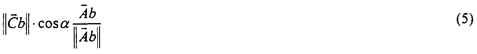


Claims
Priority Applications (8)
| Application Number | Priority Date | Filing Date | Title |
|---|---|---|---|
| JP52505297A JP4027976B2 (en) | 1996-01-08 | 1997-01-08 | Mapping catheter |
| CA002242353A CA2242353C (en) | 1996-01-08 | 1997-01-08 | Method for velocity component vector mapping |
| IL12526197A IL125261A (en) | 1996-01-08 | 1997-01-08 | Mapping catheter |
| AU11701/97A AU715925B2 (en) | 1996-01-08 | 1997-01-08 | Mapping catheter |
| DE69738547T DE69738547T2 (en) | 1996-01-08 | 1997-01-08 | CARTATING CATHETER |
| EP97900037A EP0888082B1 (en) | 1996-01-08 | 1997-01-08 | Mapping catheter |
| US09/109,802 US6600948B2 (en) | 1996-01-08 | 1998-07-02 | Method for velocity component vector mapping |
| US09/837,108 US6574492B1 (en) | 1996-01-08 | 2001-04-18 | Catheter having multiple arms with electrode and position sensor |
Applications Claiming Priority (8)
| Application Number | Priority Date | Filing Date | Title |
|---|---|---|---|
| IL116699 | 1996-01-08 | ||
| IL11669996A IL116699A (en) | 1996-01-08 | 1996-01-08 | Method of constructing cardiac map |
| US976996P | 1996-01-11 | 1996-01-11 | |
| US60/009,769 | 1996-01-11 | ||
| US08/595,365 | 1996-02-01 | ||
| US08/595,365 US5738096A (en) | 1993-07-20 | 1996-02-01 | Cardiac electromechanics |
| US1172196P | 1996-02-15 | 1996-02-15 | |
| US60/011,721 | 1996-02-15 |
Related Child Applications (2)
| Application Number | Title | Priority Date | Filing Date |
|---|---|---|---|
| US09/109,802 Continuation US6600948B2 (en) | 1996-01-08 | 1998-07-02 | Method for velocity component vector mapping |
| US09/109,802 A-371-Of-International US6600948B2 (en) | 1996-01-08 | 1998-07-02 | Method for velocity component vector mapping |
Publications (2)
| Publication Number | Publication Date |
|---|---|
| WO1997024983A2 true WO1997024983A2 (en) | 1997-07-17 |
| WO1997024983B1 WO1997024983B1 (en) | 1997-10-23 |
Family
ID=27452467
Family Applications (1)
| Application Number | Title | Priority Date | Filing Date |
|---|---|---|---|
| PCT/IL1997/000009 WO1997024983A2 (en) | 1996-01-08 | 1997-01-08 | Mapping catheter |
Country Status (9)
| Country | Link |
|---|---|
| US (2) | US6600948B2 (en) |
| EP (3) | EP0888082B1 (en) |
| JP (1) | JP4027976B2 (en) |
| AU (1) | AU715925B2 (en) |
| CA (1) | CA2242353C (en) |
| DE (1) | DE69738547T2 (en) |
| ES (2) | ES2307871T3 (en) |
| IL (2) | IL116699A (en) |
| WO (1) | WO1997024983A2 (en) |
Cited By (92)
| Publication number | Priority date | Publication date | Assignee | Title |
|---|---|---|---|---|
| WO1998029032A1 (en) | 1997-01-03 | 1998-07-09 | Biosense Inc. | Conformal catheter |
| WO1998030144A1 (en) | 1997-01-08 | 1998-07-16 | Biosense Inc. | Monitoring of myocardial revascularization |
| EP0974936A2 (en) | 1998-07-24 | 2000-01-26 | Biosense, Inc. | Three-dimensional reconstruction of intrabody organs |
| WO2000013736A1 (en) | 1998-09-03 | 2000-03-16 | H.D.S. Systems, Ltd. | Finned-tip flow guided catheters |
| US6083170A (en) * | 1996-05-17 | 2000-07-04 | Biosense, Inc. | Self-aligning catheter |
| EP1070480A2 (en) | 1999-07-22 | 2001-01-24 | Biosense, Inc. | Vector mapping of three-dimensionally reconstructed intrabody organs and method of display |
| EP1100373A1 (en) * | 1998-08-02 | 2001-05-23 | Super Dimension Ltd. | Intrabody navigation system for medical applications |
| US6272371B1 (en) | 1997-01-03 | 2001-08-07 | Biosense Inc. | Bend-responsive catheter |
| US6368285B1 (en) | 1999-09-21 | 2002-04-09 | Biosense, Inc. | Method and apparatus for mapping a chamber of a heart |
| US6385476B1 (en) | 1999-09-21 | 2002-05-07 | Biosense, Inc. | Method and apparatus for intracardially surveying a condition of a chamber of a heart |
| JP2002172097A (en) * | 2000-09-22 | 2002-06-18 | Biosense Inc | Method and device for characterizing cardiac tissue from local electrogram |
| US6447504B1 (en) | 1998-07-02 | 2002-09-10 | Biosense, Inc. | System for treatment of heart tissue using viability map |
| US6546271B1 (en) | 1999-10-01 | 2003-04-08 | Bioscience, Inc. | Vascular reconstruction |
| EP1319364A2 (en) | 2001-12-14 | 2003-06-18 | Biosense Webster, Inc. | Multiple electrode mapping catheter with location sensor |
| EP1323375A2 (en) | 2001-12-31 | 2003-07-02 | Biosense Webster, Inc. | Mapping catheter |
| US6633773B1 (en) | 2000-09-29 | 2003-10-14 | Biosene, Inc. | Area of interest reconstruction for surface of an organ using location data |
| US6650927B1 (en) | 2000-08-18 | 2003-11-18 | Biosense, Inc. | Rendering of diagnostic imaging data on a three-dimensional map |
| EP1393674A1 (en) | 2002-08-30 | 2004-03-03 | Biosense Webster, Inc. | Catheter and method for mapping Purkinje fibers |
| EP1484025A1 (en) * | 1998-03-05 | 2004-12-08 | Boston Scientific Limited | Catheter assembly with electrode |
| US6992477B2 (en) | 2001-06-15 | 2006-01-31 | Biosense, Inc. | Medical device with position sensor having core with high permeability material for determining location coordinates of a portion of the medical device |
| US7003342B2 (en) | 2003-06-02 | 2006-02-21 | Biosense Webster, Inc. | Catheter and method for mapping a pulmonary vein |
| US7286868B2 (en) | 2001-06-15 | 2007-10-23 | Biosense Inc. | Medical device with position sensor having accuracy at high temperatures |
| WO2008004010A2 (en) * | 2006-07-07 | 2008-01-10 | Lectus Therapeutics Limited | Apparatus and methods |
| WO2008044147A2 (en) * | 2006-10-13 | 2008-04-17 | Didier Chatel | Device for the implantation of a therapeutic or diagnostic apparatus in or on a mammalian internal organ |
| US7366557B2 (en) | 2003-11-07 | 2008-04-29 | Biosense Webster, Inc. | Flower catheter |
| WO2008157727A2 (en) * | 2007-06-19 | 2008-12-24 | Calypso Medical Technologies, Inc. | Methods and apparatus for external beam radiation treatments of resection cavities |
| EP2151209A2 (en) | 2008-08-06 | 2010-02-10 | Biosense Webster | Single-axis sensors on flexible backbone |
| US7678104B2 (en) | 2003-07-17 | 2010-03-16 | Biosense Webster, Inc. | Ultrasound ablation catheter and method for its use |
| US7727230B2 (en) | 2002-07-19 | 2010-06-01 | Biosense-Webster, Inc. | Atrial ablation catheter and method for treating atrial fibrillation |
| EP1420690B1 (en) * | 2001-08-30 | 2010-06-09 | C.R. Bard, Inc. | Software controlled electrophysiology data management |
| US7818048B2 (en) | 2003-06-02 | 2010-10-19 | Biosense Webster, Inc. | Catheter and method for mapping a pulmonary vein |
| EP2332461A1 (en) * | 2009-12-08 | 2011-06-15 | Biosense Webster (Israel), Ltd | Probe data mapping using contact information |
| EP2421607A2 (en) * | 2009-04-21 | 2012-02-29 | Incube Labs, Llc | Apparatus and method for the detection and treatment of atrial fibrillation |
| US8133220B2 (en) | 2003-06-02 | 2012-03-13 | Biosense Webster, Inc. | Enhanced ablation and mapping catheter and method for treating atrial fibrillation |
| EP2471446A2 (en) | 2010-12-30 | 2012-07-04 | Biosense Webster (Israel), Ltd. | Catheter with sheet array of electrodes |
| US8452068B2 (en) | 2008-06-06 | 2013-05-28 | Covidien Lp | Hybrid registration method |
| US8473032B2 (en) | 2008-06-03 | 2013-06-25 | Superdimension, Ltd. | Feature-based registration method |
| US8521266B2 (en) | 2008-10-09 | 2013-08-27 | The Regents Of The University Of California | Methods for the detection and/or diagnosis of biological rhythm disorders |
| EP2641556A1 (en) | 2012-03-21 | 2013-09-25 | Biosense Webster (Israel), Ltd. | Flower catheter for mapping and ablating veinous and other tubular locations |
| JP2014506171A (en) * | 2010-12-30 | 2014-03-13 | セント・ジュード・メディカル・エイトリアル・フィブリレーション・ディヴィジョン・インコーポレーテッド | System and method for arrhythmia diagnosis and catheter therapy |
| US8676303B2 (en) | 2008-05-13 | 2014-03-18 | The Regents Of The University Of California | Methods and systems for treating heart instability |
| EP2752153A1 (en) | 2013-01-08 | 2014-07-09 | Nhut Diep | Catheter with multiple spines of different lengths arranged in one or more distal assemblies |
| US8934975B2 (en) | 2010-02-01 | 2015-01-13 | Metacure Limited | Gastrointestinal electrical therapy |
| US8958872B2 (en) | 1996-01-08 | 2015-02-17 | Impulse Dynamics, N.V. | Electrical muscle controller |
| US8977353B2 (en) | 2004-03-10 | 2015-03-10 | Impulse Dynamics Nv | Protein activity modification |
| EP2848226A1 (en) | 2013-09-16 | 2015-03-18 | Biosense Webster (Israel), Ltd. | Basket catheter with deflectable spine |
| EP2881059A1 (en) | 2013-12-05 | 2015-06-10 | Biosense Webster (Israel), Ltd. | Needle catheter utilizing optical spectroscopy for tumor identification and ablation |
| EP2889013A1 (en) | 2013-12-31 | 2015-07-01 | Biosense Webster (Israel), Ltd. | Catheter utilizing optical spectroscopy for measuring tissue contact area |
| US9101765B2 (en) | 1999-03-05 | 2015-08-11 | Metacure Limited | Non-immediate effects of therapy |
| US9107993B2 (en) | 2011-11-21 | 2015-08-18 | Incube Labs, Llc | Myocardial drug delivery apparatus and method |
| US9131853B2 (en) | 2011-07-01 | 2015-09-15 | Joseph Tiano | Medical probe and method of using same |
| EP2942024A2 (en) | 2014-04-18 | 2015-11-11 | Biosense Webster (Israel) Ltd. | Ablation catheter with dedicated fluid paths and needle centering insert |
| US9220427B2 (en) | 2011-05-02 | 2015-12-29 | The Regents Of The University Of California | System and method for reconstructing cardiac activation information |
| EP2615969A4 (en) * | 2010-09-17 | 2016-01-06 | Cardioinsight Technologies Inc | System and methods for computing activation maps |
| US9241667B2 (en) | 2010-04-08 | 2016-01-26 | The Regents Of The University Of California | System and method for reconstructing cardiac signals associated with a complex rhythm disorder |
| US9289618B1 (en) | 1996-01-08 | 2016-03-22 | Impulse Dynamics Nv | Electrical muscle controller |
| US9314208B1 (en) | 2014-10-28 | 2016-04-19 | Biosense Webster (Israel) Ltd. | Basket catheter with microelectrode array distal tip |
| US9326813B2 (en) | 2003-10-27 | 2016-05-03 | Biosense Webster, Inc. | Method for ablating with needle electrode |
| WO2015179634A3 (en) * | 2014-05-22 | 2016-05-19 | CARDIONOMIC, Inc. | Catheter and catheter system for electrical neuromodulation |
| JP2016521180A (en) * | 2013-05-07 | 2016-07-21 | セント・ジュード・メディカル・エイトリアル・フィブリレーション・ディヴィジョン・インコーポレーテッド | Using the spatial arrangement of electrodes to characterize cardiac conduction status |
| US9398883B2 (en) | 2011-05-02 | 2016-07-26 | The Regents Of The University Of California | System and method for reconstructing cardiac activation information |
| US9468494B2 (en) | 2003-07-18 | 2016-10-18 | Biosense Webster, Inc. | Enhanced ablation and mapping catheter and method for treating atrial fibrillation |
| US9468387B2 (en) | 2011-05-02 | 2016-10-18 | The Regents Of The University Of California | System and method for reconstructing cardiac activation information |
| US9480790B2 (en) | 2005-09-12 | 2016-11-01 | The Cleveland Clinic Foundation | Methods and systems for treating acute heart failure by neuromodulation |
| US9592091B2 (en) | 2011-08-30 | 2017-03-14 | Biosense Webster (Israel) Ltd. | Ablation catheter for vein anatomies |
| US9655535B2 (en) | 2011-05-02 | 2017-05-23 | The Regents Of The University Of California | System and method for targeting heart rhythm disorders using shaped ablation |
| EP3184037A1 (en) | 2015-12-23 | 2017-06-28 | Biosense Webster (Israel), Ltd. | Catheter frame pieces used as large single axis sensors |
| US9713723B2 (en) | 1996-01-11 | 2017-07-25 | Impulse Dynamics Nv | Signal delivery through the right ventricular septum |
| US9782099B2 (en) | 2014-12-31 | 2017-10-10 | Biosense Webster (Israel) Ltd. | Basket catheter with improved spine flexibility |
| US9931503B2 (en) | 2003-03-10 | 2018-04-03 | Impulse Dynamics Nv | Protein activity modification |
| US10058262B2 (en) | 2011-12-09 | 2018-08-28 | The Regents Of The University Of California | System and method of identifying sources for biological rhythms |
| US10085655B2 (en) | 2013-03-15 | 2018-10-02 | The Regents Of The University Of California | System and method to define drivers of sources associated with biological rhythm disorders |
| US10136829B2 (en) | 2014-02-25 | 2018-11-27 | St. Jude Medical, Cardiology Division, Inc. | Systems and methods for using electrophysiology properties for classifying arrhythmia sources |
| EP3417769A1 (en) | 2017-06-21 | 2018-12-26 | Biosense Webster (Israel) Ltd. | Combination torso vest to map cardiac electrophysiology |
| US10172549B2 (en) | 2016-03-09 | 2019-01-08 | CARDIONOMIC, Inc. | Methods of facilitating positioning of electrodes |
| US10194994B2 (en) | 2015-05-12 | 2019-02-05 | St. Jude Medical, Cardiology Division, Inc. | Systems and methods for orientation independent sensing |
| US10389847B1 (en) | 2015-12-23 | 2019-08-20 | Mitel Networks, Inc. | Provisioning resources in a communications system |
| US10434319B2 (en) | 2009-10-09 | 2019-10-08 | The Regents Of The University Of California | System and method of identifying sources associated with biological rhythm disorders |
| US10493278B2 (en) | 2015-01-05 | 2019-12-03 | CARDIONOMIC, Inc. | Cardiac modulation facilitation methods and systems |
| CN110691559A (en) * | 2017-05-30 | 2020-01-14 | 韦伯斯特生物官能(以色列)有限公司 | Catheter spline as position sensor |
| US10722716B2 (en) | 2014-09-08 | 2020-07-28 | Cardionomia Inc. | Methods for electrical neuromodulation of the heart |
| US10758137B2 (en) | 2017-04-14 | 2020-09-01 | St. Jude Medical, Cardiology Division, Inc. | Orientation independent sensing, mapping, interface and analysis systems and methods |
| US10894160B2 (en) | 2014-09-08 | 2021-01-19 | CARDIONOMIC, Inc. | Catheter and electrode systems for electrical neuromodulation |
| US11077298B2 (en) | 2018-08-13 | 2021-08-03 | CARDIONOMIC, Inc. | Partially woven expandable members |
| US11331424B2 (en) | 2009-01-26 | 2022-05-17 | Incube Labs, Llc | Apparatus, systems and methods for delivery of medication to the brain to treat neurological conditions |
| US11369306B2 (en) | 2018-09-10 | 2022-06-28 | St. Jude Medical, Cardiology Division, Inc. | System and method for displaying electrophysiological signals from multi-dimensional catheters |
| US11439815B2 (en) | 2003-03-10 | 2022-09-13 | Impulse Dynamics Nv | Protein activity modification |
| US11559687B2 (en) | 2017-09-13 | 2023-01-24 | CARDIONOMIC, Inc. | Methods for detecting catheter movement |
| US11607176B2 (en) | 2019-05-06 | 2023-03-21 | CARDIONOMIC, Inc. | Systems and methods for denoising physiological signals during electrical neuromodulation |
| US11751794B2 (en) | 2020-05-19 | 2023-09-12 | St. Jude Medical, Cardiology Division, Inc. | System and method for mapping electrophysiological activation |
| US11779768B2 (en) | 2004-03-10 | 2023-10-10 | Impulse Dynamics Nv | Protein activity modification |
| US11944344B2 (en) | 2018-04-13 | 2024-04-02 | Karl Storz Se & Co. Kg | Guidance system, method and devices thereof |
Families Citing this family (195)
| Publication number | Priority date | Publication date | Assignee | Title |
|---|---|---|---|---|
| US6136019A (en) * | 1996-08-19 | 2000-10-24 | Mower Family Chf Treatment Irrevocable Trust | Augmentation of electrical conduction and contractility by biphasic cardiac pacing administered via the cardiac blood pool |
| EP2362283B1 (en) * | 1997-09-19 | 2015-11-25 | Massachusetts Institute Of Technology | Robotic apparatus |
| SE9801006D0 (en) * | 1998-03-25 | 1998-03-25 | Siemens Elema Ab | Method and arrangement for determining the location of a catheter within an animal body |
| TW444039B (en) * | 1999-02-02 | 2001-07-01 | Dow Chemical Co | Open-celled polyurethane foams containing graphite which exhibit low thermal conductivity |
| US6662034B2 (en) * | 2000-11-15 | 2003-12-09 | Stereotaxis, Inc. | Magnetically guidable electrophysiology catheter |
| US6950696B2 (en) * | 2001-11-27 | 2005-09-27 | St. Jude Medical Ab | Method and circuit for detecting cardiac rhythm abnormalities by analyzing time differences between unipolar signals from a lead with a multi-electrode tip |
| US20030199961A1 (en) * | 2002-04-03 | 2003-10-23 | Bjorklund Vicki L. | Method and apparatus for fixating a pacing lead of an implantable medical device |
| US7769427B2 (en) * | 2002-07-16 | 2010-08-03 | Magnetics, Inc. | Apparatus and method for catheter guidance control and imaging |
| US6892090B2 (en) | 2002-08-19 | 2005-05-10 | Surgical Navigation Technologies, Inc. | Method and apparatus for virtual endoscopy |
| DE10247150B4 (en) * | 2002-10-09 | 2007-08-02 | Siemens Ag | Method for processing magnetic resonance raw data |
| US20040082947A1 (en) * | 2002-10-25 | 2004-04-29 | The Regents Of The University Of Michigan | Ablation catheters |
| US20050033137A1 (en) * | 2002-10-25 | 2005-02-10 | The Regents Of The University Of Michigan | Ablation catheters and methods for their use |
| WO2004062525A2 (en) * | 2003-01-16 | 2004-07-29 | Galil Medical Ltd. | Device, system, and method for detecting and localizing obstruction within a blood vessel |
| US20060106321A1 (en) * | 2003-01-16 | 2006-05-18 | Galil Medical Ltd. | Device, system, and method for detecting, localizing, and characterizing plaque-induced stenosis of a blood vessel |
| AU2003302233A1 (en) * | 2003-02-04 | 2004-09-06 | Arizona Board Of Regents, Acting For And On Behalf Of Arizona State University (Abr/Asu) | Using benzocyclobutene as a biocompatible material |
| US20050070981A1 (en) * | 2003-09-29 | 2005-03-31 | Sumit Verma | Active fixation coronary sinus lead apparatus |
| US7280863B2 (en) * | 2003-10-20 | 2007-10-09 | Magnetecs, Inc. | System and method for radar-assisted catheter guidance and control |
| US7179256B2 (en) * | 2003-10-24 | 2007-02-20 | Biosense Webster, Inc. | Catheter with ablation needle and mapping assembly |
| US20050096543A1 (en) * | 2003-11-03 | 2005-05-05 | Jackson John I. | Motion tracking for medical imaging |
| US9237929B2 (en) * | 2003-12-22 | 2016-01-19 | Koninklijke Philips N.V. | System for guiding a medical instrument in a patient body |
| US7966058B2 (en) * | 2003-12-31 | 2011-06-21 | General Electric Company | System and method for registering an image with a representation of a probe |
| US20080188740A1 (en) * | 2004-01-14 | 2008-08-07 | Diaz Cesar M | Apparatus and method for guiding catheters |
| US20070219444A1 (en) * | 2004-01-14 | 2007-09-20 | Diaz Cesar M | Apparatus and method for guiding catheters |
| CA2555473A1 (en) | 2004-02-17 | 2005-09-01 | Traxtal Technologies Inc. | Method and apparatus for registration, verification, and referencing of internal organs |
| EP1720480A1 (en) * | 2004-03-05 | 2006-11-15 | Hansen Medical, Inc. | Robotic catheter system |
| US8010175B2 (en) * | 2004-05-05 | 2011-08-30 | Siemens Medical Solutions Usa, Inc. | Patient-specific coronary territory mapping |
| US7087053B2 (en) * | 2004-05-27 | 2006-08-08 | St. Jude Medical, Atrial Fibrillation Division, Inc. | Catheter with bifurcated, collapsible tip for sensing and ablating |
| US20090216115A1 (en) * | 2004-07-23 | 2009-08-27 | Calypso Medical Technologies, Inc. | Anchoring wirless markers within a human body |
| US20060089637A1 (en) | 2004-10-14 | 2006-04-27 | Werneth Randell L | Ablation catheter |
| US7722565B2 (en) | 2004-11-05 | 2010-05-25 | Traxtal, Inc. | Access system |
| US7805269B2 (en) | 2004-11-12 | 2010-09-28 | Philips Electronics Ltd | Device and method for ensuring the accuracy of a tracking device in a volume |
| US7751868B2 (en) | 2004-11-12 | 2010-07-06 | Philips Electronics Ltd | Integrated skin-mounted multifunction device for use in image-guided surgery |
| KR100689707B1 (en) * | 2004-11-12 | 2007-03-08 | 삼성전자주식회사 | Bank selection signal control circuit, semiconductor memory device having the same and method for control bank selection signal |
| US8617152B2 (en) | 2004-11-15 | 2013-12-31 | Medtronic Ablation Frontiers Llc | Ablation system with feedback |
| US7468062B2 (en) | 2004-11-24 | 2008-12-23 | Ablation Frontiers, Inc. | Atrial ablation catheter adapted for treatment of septal wall arrhythmogenic foci and method of use |
| US7429261B2 (en) | 2004-11-24 | 2008-09-30 | Ablation Frontiers, Inc. | Atrial ablation catheter and method of use |
| EP1868497A2 (en) * | 2005-01-11 | 2007-12-26 | Stereotaxis, Inc. | Navigation using sensed physiological data as feedback |
| US20070225589A1 (en) * | 2005-01-11 | 2007-09-27 | Viswanathan Raju R | Single catheter diagnosis, navigation and treatment of arrhythmias |
| US8611983B2 (en) | 2005-01-18 | 2013-12-17 | Philips Electronics Ltd | Method and apparatus for guiding an instrument to a target in the lung |
| EP1838215B1 (en) | 2005-01-18 | 2012-08-01 | Philips Electronics LTD | Electromagnetically tracked k-wire device |
| US10143398B2 (en) | 2005-04-26 | 2018-12-04 | Biosense Webster, Inc. | Registration of ultrasound data with pre-acquired image |
| US8027714B2 (en) * | 2005-05-27 | 2011-09-27 | Magnetecs, Inc. | Apparatus and method for shaped magnetic field control for catheter, guidance, control, and imaging |
| US7850685B2 (en) | 2005-06-20 | 2010-12-14 | Medtronic Ablation Frontiers Llc | Ablation catheter |
| EP1898775B1 (en) | 2005-06-21 | 2013-02-13 | Philips Electronics LTD | System and apparatus for navigated therapy and diagnosis |
| CA2612603C (en) | 2005-06-21 | 2015-05-19 | Traxtal Inc. | Device and method for a trackable ultrasound |
| EP1909679B1 (en) | 2005-07-11 | 2013-11-20 | Medtronic Ablation Frontiers LLC | Low power tissue ablation system |
| US8657814B2 (en) * | 2005-08-22 | 2014-02-25 | Medtronic Ablation Frontiers Llc | User interface for tissue ablation system |
| US9661991B2 (en) | 2005-08-24 | 2017-05-30 | Koninklijke Philips N.V. | System, method and devices for navigated flexible endoscopy |
| US7885707B2 (en) | 2005-09-15 | 2011-02-08 | St. Jude Medical, Atrial Fibrillation Division, Inc. | Method of scaling navigation signals to account for impedance drift in tissue |
| US20070071295A1 (en) * | 2005-09-27 | 2007-03-29 | Siemens Medical Solutions Usa, Inc. | Orientation-based assessment of cardiac synchrony in medical imaging |
| US20090216113A1 (en) | 2005-11-17 | 2009-08-27 | Eric Meier | Apparatus and Methods for Using an Electromagnetic Transponder in Orthopedic Procedures |
| US8764664B2 (en) * | 2005-11-28 | 2014-07-01 | Vizyontech Imaging, Inc. | Methods and apparatus for conformable medical data acquisition pad and configurable imaging system |
| EP1800599A1 (en) * | 2005-12-23 | 2007-06-27 | Nederlandse Organisatie voor toegepast-natuurwetenschappelijk Onderzoek TNO | Diagnostic electrode configuration |
| US7957789B2 (en) | 2005-12-30 | 2011-06-07 | Medtronic, Inc. | Therapy delivery system including a navigation element |
| US7525309B2 (en) | 2005-12-30 | 2009-04-28 | Depuy Products, Inc. | Magnetic sensor array |
| US8862200B2 (en) | 2005-12-30 | 2014-10-14 | DePuy Synthes Products, LLC | Method for determining a position of a magnetic source |
| US20070161888A1 (en) * | 2005-12-30 | 2007-07-12 | Sherman Jason T | System and method for registering a bone of a patient with a computer assisted orthopaedic surgery system |
| US7869854B2 (en) * | 2006-02-23 | 2011-01-11 | Magnetecs, Inc. | Apparatus for magnetically deployable catheter with MOSFET sensor and method for mapping and ablation |
| US7515954B2 (en) * | 2006-06-13 | 2009-04-07 | Rhythmia Medical, Inc. | Non-contact cardiac mapping, including moving catheter and multi-beat integration |
| US7505810B2 (en) * | 2006-06-13 | 2009-03-17 | Rhythmia Medical, Inc. | Non-contact cardiac mapping, including preprocessing |
| US7729752B2 (en) * | 2006-06-13 | 2010-06-01 | Rhythmia Medical, Inc. | Non-contact cardiac mapping, including resolution map |
| EP3603500B1 (en) | 2006-08-03 | 2021-03-31 | Christoph Scharf | Device for determining and presenting surface charge and dipole densities on cardiac walls |
| US8068648B2 (en) | 2006-12-21 | 2011-11-29 | Depuy Products, Inc. | Method and system for registering a bone of a patient with a computer assisted orthopaedic surgery system |
| US7894871B2 (en) * | 2006-12-29 | 2011-02-22 | St. Jude Medical, Atrial Fibrillation Division, Inc. | Filtering method for surface modeling |
| US20080190438A1 (en) * | 2007-02-08 | 2008-08-14 | Doron Harlev | Impedance registration and catheter tracking |
| DE102007007563B4 (en) * | 2007-02-15 | 2010-07-22 | Siemens Ag | Method and medical device for determining the cardiac conduction |
| US8515521B2 (en) * | 2007-05-01 | 2013-08-20 | St. Jude Medical, Atrial Fibrillation Division, Inc. | Coupler assembly for catheters |
| US8641704B2 (en) | 2007-05-11 | 2014-02-04 | Medtronic Ablation Frontiers Llc | Ablation therapy system and method for treating continuous atrial fibrillation |
| US20080297287A1 (en) * | 2007-05-30 | 2008-12-04 | Magnetecs, Inc. | Magnetic linear actuator for deployable catheter tools |
| US7908004B1 (en) * | 2007-08-30 | 2011-03-15 | Pacesetter, Inc. | Considering cardiac ischemia in electrode selection |
| US8825134B2 (en) * | 2007-09-14 | 2014-09-02 | Siemens Aktiengesellschaft | Catheter localization system |
| US8357152B2 (en) | 2007-10-08 | 2013-01-22 | Biosense Webster (Israel), Ltd. | Catheter with pressure sensing |
| US8535308B2 (en) * | 2007-10-08 | 2013-09-17 | Biosense Webster (Israel), Ltd. | High-sensitivity pressure-sensing probe |
| US8103327B2 (en) | 2007-12-28 | 2012-01-24 | Rhythmia Medical, Inc. | Cardiac mapping catheter |
| WO2009090547A2 (en) | 2008-01-17 | 2009-07-23 | Christoph Scharf | A device and method for the geometric determination of electrical dipole densities on the cardiac wall |
| US8538509B2 (en) | 2008-04-02 | 2013-09-17 | Rhythmia Medical, Inc. | Intracardiac tracking system |
| WO2009122273A2 (en) | 2008-04-03 | 2009-10-08 | Superdimension, Ltd. | Magnetic interference detection system and method |
| US8437832B2 (en) | 2008-06-06 | 2013-05-07 | Biosense Webster, Inc. | Catheter with bendable tip |
| US9101734B2 (en) * | 2008-09-09 | 2015-08-11 | Biosense Webster, Inc. | Force-sensing catheter with bonded center strut |
| US8167876B2 (en) | 2008-10-27 | 2012-05-01 | Rhythmia Medical, Inc. | Tracking system using field mapping |
| US8457714B2 (en) * | 2008-11-25 | 2013-06-04 | Magnetecs, Inc. | System and method for a catheter impedance seeking device |
| US9326700B2 (en) | 2008-12-23 | 2016-05-03 | Biosense Webster (Israel) Ltd. | Catheter display showing tip angle and pressure |
| US8600472B2 (en) * | 2008-12-30 | 2013-12-03 | Biosense Webster (Israel), Ltd. | Dual-purpose lasso catheter with irrigation using circumferentially arranged ring bump electrodes |
| US8475450B2 (en) * | 2008-12-30 | 2013-07-02 | Biosense Webster, Inc. | Dual-purpose lasso catheter with irrigation |
| US8700129B2 (en) * | 2008-12-31 | 2014-04-15 | St. Jude Medical, Atrial Fibrillation Division, Inc. | Devices and methods for catheter localization |
| US9943704B1 (en) | 2009-01-21 | 2018-04-17 | Varian Medical Systems, Inc. | Method and system for fiducials contained in removable device for radiation therapy |
| US8374703B2 (en) * | 2009-01-26 | 2013-02-12 | Incube Labs, Llc | Method and apparatus for the detection of aberrant neural-electric activity |
| US9398862B2 (en) | 2009-04-23 | 2016-07-26 | Rhythmia Medical, Inc. | Multi-electrode mapping system |
| US8571647B2 (en) * | 2009-05-08 | 2013-10-29 | Rhythmia Medical, Inc. | Impedance based anatomy generation |
| US8103338B2 (en) | 2009-05-08 | 2012-01-24 | Rhythmia Medical, Inc. | Impedance based anatomy generation |
| US8774906B2 (en) * | 2009-05-15 | 2014-07-08 | Koninklijke Philips N.V. | Apparatus, method and computer program for determining a property of a heart |
| US20110112396A1 (en) | 2009-11-09 | 2011-05-12 | Magnetecs, Inc. | System and method for targeting catheter electrodes |
| US10688278B2 (en) * | 2009-11-30 | 2020-06-23 | Biosense Webster (Israel), Ltd. | Catheter with pressure measuring tip |
| US8920415B2 (en) * | 2009-12-16 | 2014-12-30 | Biosense Webster (Israel) Ltd. | Catheter with helical electrode |
| US8521462B2 (en) | 2009-12-23 | 2013-08-27 | Biosense Webster (Israel), Ltd. | Calibration system for a pressure-sensitive catheter |
| US8529476B2 (en) * | 2009-12-28 | 2013-09-10 | Biosense Webster (Israel), Ltd. | Catheter with strain gauge sensor |
| US8608735B2 (en) * | 2009-12-30 | 2013-12-17 | Biosense Webster (Israel) Ltd. | Catheter with arcuate end section |
| US8374670B2 (en) * | 2010-01-22 | 2013-02-12 | Biosense Webster, Inc. | Catheter having a force sensing distal tip |
| US9131869B2 (en) | 2010-05-11 | 2015-09-15 | Rhythmia Medical, Inc. | Tracking using field mapping |
| US8798952B2 (en) | 2010-06-10 | 2014-08-05 | Biosense Webster (Israel) Ltd. | Weight-based calibration system for a pressure sensitive catheter |
| US8226580B2 (en) | 2010-06-30 | 2012-07-24 | Biosense Webster (Israel), Ltd. | Pressure sensing for a multi-arm catheter |
| US8380276B2 (en) | 2010-08-16 | 2013-02-19 | Biosense Webster, Inc. | Catheter with thin film pressure sensing distal tip |
| JP5565578B2 (en) * | 2010-10-04 | 2014-08-06 | セイコーエプソン株式会社 | Weather change prediction information providing system and weather change prediction information providing method |
| US8731859B2 (en) | 2010-10-07 | 2014-05-20 | Biosense Webster (Israel) Ltd. | Calibration system for a force-sensing catheter |
| US8979772B2 (en) | 2010-11-03 | 2015-03-17 | Biosense Webster (Israel), Ltd. | Zero-drift detection and correction in contact force measurements |
| US8617087B2 (en) | 2010-12-03 | 2013-12-31 | Biosense Webster, Inc. | Control handle with rotational cam mechanism for contraction/deflection of medical device |
| US8792962B2 (en) | 2010-12-30 | 2014-07-29 | Biosense Webster, Inc. | Catheter with single axial sensors |
| US9002442B2 (en) | 2011-01-13 | 2015-04-07 | Rhythmia Medical, Inc. | Beat alignment and selection for cardiac mapping |
| US9277872B2 (en) | 2011-01-13 | 2016-03-08 | Rhythmia Medical, Inc. | Electroanatomical mapping |
| EP2683293B1 (en) | 2011-03-10 | 2019-07-17 | Acutus Medical, Inc. | Device for the geometric determination of electrical dipole densities on the cardiac wall |
| CN102274018B (en) * | 2011-05-23 | 2014-07-09 | 成正辉 | Fast-switching and mapping catheter, and preparation method and application method thereof |
| AU2012273146B2 (en) * | 2011-06-21 | 2015-03-19 | Cook Medical Technologies Llc | Expandable probe |
| US9220433B2 (en) * | 2011-06-30 | 2015-12-29 | Biosense Webster (Israel), Ltd. | Catheter with variable arcuate distal section |
| US9662169B2 (en) | 2011-07-30 | 2017-05-30 | Biosense Webster (Israel) Ltd. | Catheter with flow balancing valve |
| US9687289B2 (en) | 2012-01-04 | 2017-06-27 | Biosense Webster (Israel) Ltd. | Contact assessment based on phase measurement |
| EP3868283A1 (en) | 2012-08-31 | 2021-08-25 | Acutus Medical Inc. | Catheter system for the heart |
| US9895079B2 (en) * | 2012-09-26 | 2018-02-20 | Biosense Webster (Israel) Ltd. | Electropotential mapping |
| JP2016501640A (en) | 2012-12-20 | 2016-01-21 | ボストン サイエンティフィック サイムド,インコーポレイテッドBoston Scientific Scimed,Inc. | Rotor identification using time-series pattern matching |
| US9204820B2 (en) | 2012-12-31 | 2015-12-08 | Biosense Webster (Israel) Ltd. | Catheter with combined position and pressure sensing structures |
| US9204841B2 (en) | 2012-12-31 | 2015-12-08 | Biosense Webster (Israel) Ltd. | Catheter with serially connected sensing structures and methods of calibration and detection |
| JP6240751B2 (en) | 2013-05-06 | 2017-11-29 | ボストン サイエンティフィック サイムド,インコーポレイテッドBoston Scientific Scimed,Inc. | Anatomic mapping system for continuous display of recent heart rate characteristics during real-time or playback electrophysiological data visualization |
| CN105228510B (en) | 2013-05-14 | 2018-12-14 | 波士顿科学医学有限公司 | The expression and identification of the activity pattern of vector field are used during electrophysiology mapping |
| US9144391B2 (en) | 2013-05-16 | 2015-09-29 | Boston Scientific Scimed Inc. | Enhanced activation onset time optimization by similarity based pattern matching |
| JP2015020030A (en) * | 2013-07-23 | 2015-02-02 | シャープ株式会社 | Biological sound collection apparatus |
| US9737227B2 (en) | 2013-08-28 | 2017-08-22 | Boston Scientific Scimed Inc. | Estimating the prevalence of activation patterns in data segments during electrophysiology mapping |
| AU2014318872B2 (en) | 2013-09-13 | 2018-09-13 | Acutus Medical, Inc. | Devices and methods for determination of electrical dipole densities on a cardiac surface |
| WO2015057521A1 (en) | 2013-10-14 | 2015-04-23 | Boston Scientific Scimed, Inc. | High resolution cardiac mapping electrode array catheter |
| US9078575B2 (en) * | 2013-10-30 | 2015-07-14 | Apn Health, Llc | Heartbeat categorization |
| CN105636513B (en) | 2013-10-31 | 2020-05-12 | 波士顿科学医学有限公司 | Medical device for high resolution mapping using local matching |
| US9554718B2 (en) | 2014-01-29 | 2017-01-31 | Biosense Webster (Israel) Ltd. | Double bipolar configuration for atrial fibrillation annotation |
| US9750422B2 (en) * | 2014-02-12 | 2017-09-05 | Biosense Webster (Israel) Ltd | Catheter with transverse branches |
| US9986949B2 (en) | 2014-03-05 | 2018-06-05 | Biosense Webster (Israel) Ltd. | Multi-arm catheter with signal transmission over braid wires |
| WO2015148470A1 (en) | 2014-03-25 | 2015-10-01 | Acutus Medical, Inc. | Cardiac analysis user interface system and method |
| CN106413540A (en) | 2014-06-03 | 2017-02-15 | 波士顿科学医学有限公司 | Electrode assembly having an atraumatic distal tip |
| EP3151773B1 (en) | 2014-06-04 | 2018-04-04 | Boston Scientific Scimed, Inc. | Electrode assembly |
| EP3157419A1 (en) | 2014-06-20 | 2017-04-26 | Boston Scientific Scimed Inc. | Medical devices for mapping cardiac tissue |
| US9446230B1 (en) | 2014-09-04 | 2016-09-20 | Advanced Bionics Ag | Cochlear implant electrode array and method for inserting the same into a human cochlea |
| ES2529702B1 (en) * | 2014-09-12 | 2015-09-29 | Universitat Politècnica De València | Catheter and method for detecting electrical activity in an organ |
| CN107072574B (en) * | 2014-10-15 | 2020-06-12 | 圣犹达医疗用品心脏病学部门有限公司 | Method and system for mapping local conduction velocity |
| EP3220828B1 (en) | 2014-11-18 | 2021-12-22 | C.R. Bard, Inc. | Ultrasound imaging system having automatic image presentation |
| WO2016081321A2 (en) | 2014-11-18 | 2016-05-26 | C.R. Bard, Inc. | Ultrasound imaging system having automatic image presentation |
| US9662033B2 (en) * | 2014-12-31 | 2017-05-30 | Biosense Webster (Israel) Ltd. | System and method for visualizing electrophysiology data |
| AU2016262547B9 (en) | 2015-05-12 | 2021-03-04 | Acutus Medical, Inc. | Ultrasound sequencing system and method |
| WO2016183179A1 (en) | 2015-05-12 | 2016-11-17 | Acutus Medical, Inc. | Cardiac virtualization test tank and testing system and method |
| WO2016183468A1 (en) | 2015-05-13 | 2016-11-17 | Acutus Medical, Inc. | Localization system and method useful in the acquisition and analysis of cardiac information |
| US10758144B2 (en) | 2015-08-20 | 2020-09-01 | Boston Scientific Scimed Inc. | Flexible electrode for cardiac sensing and method for making |
| CN108348155B (en) | 2015-09-02 | 2019-02-01 | 圣犹达医疗用品心脏病学部门有限公司 | For identification with the method and system of mapping heart excitement wavefront |
| US10405766B2 (en) | 2015-09-26 | 2019-09-10 | Boston Scientific Scimed, Inc. | Method of exploring or mapping internal cardiac structures |
| CN108024747B (en) | 2015-09-26 | 2020-12-04 | 波士顿科学医学有限公司 | Intracardiac EGM signal for beat matching and acceptance |
| JP6691209B2 (en) | 2015-09-26 | 2020-04-28 | ボストン サイエンティフィック サイムド,インコーポレイテッドBoston Scientific Scimed,Inc. | Methods for editing anatomical shells |
| US10271757B2 (en) | 2015-09-26 | 2019-04-30 | Boston Scientific Scimed Inc. | Multiple rhythm template monitoring |
| CN108366734A (en) * | 2015-12-20 | 2018-08-03 | 波士顿科学医学有限公司 | The automatic mapping of operating speed information |
| US10849521B2 (en) | 2015-12-23 | 2020-12-01 | Biosense Webster (Israel) Ltd. | Multi-layered catheter shaft construction with embedded single axial sensors, and related methods |
| US10582894B2 (en) | 2016-01-14 | 2020-03-10 | Biosense Webster (Israel) Ltd. | Region of interest rotational activity pattern detection |
| US11006887B2 (en) | 2016-01-14 | 2021-05-18 | Biosense Webster (Israel) Ltd. | Region of interest focal source detection using comparisons of R-S wave magnitudes and LATs of RS complexes |
| US10314542B2 (en) | 2016-01-14 | 2019-06-11 | Biosense Webster (Israel) Ltd. | Identification of fractionated signals |
| US10624554B2 (en) | 2016-01-14 | 2020-04-21 | Biosense Webster (Israel) Ltd. | Non-overlapping loop-type or spline-type catheter to determine activation source direction and activation source type |
| US10517496B2 (en) | 2016-01-14 | 2019-12-31 | Biosense Webster (Israel) Ltd. | Region of interest focal source detection |
| EP3973908A1 (en) | 2016-05-03 | 2022-03-30 | Acutus Medical Inc. | Cardiac mapping system with efficiency algorithm |
| JP6781325B2 (en) * | 2016-07-15 | 2020-11-04 | セント・ジュード・メディカル,カーディオロジー・ディヴィジョン,インコーポレイテッド | Impedance shift detection |
| EP3518741B1 (en) * | 2016-09-27 | 2020-09-16 | Cardiac Pacemakers, Inc. | Mapping and/or ablation catheter with a closed distal loop |
| US10792106B2 (en) | 2016-10-28 | 2020-10-06 | Covidien Lp | System for calibrating an electromagnetic navigation system |
| US10722311B2 (en) | 2016-10-28 | 2020-07-28 | Covidien Lp | System and method for identifying a location and/or an orientation of an electromagnetic sensor based on a map |
| US10517505B2 (en) | 2016-10-28 | 2019-12-31 | Covidien Lp | Systems, methods, and computer-readable media for optimizing an electromagnetic navigation system |
| US10638952B2 (en) | 2016-10-28 | 2020-05-05 | Covidien Lp | Methods, systems, and computer-readable media for calibrating an electromagnetic navigation system |
| US10446931B2 (en) | 2016-10-28 | 2019-10-15 | Covidien Lp | Electromagnetic navigation antenna assembly and electromagnetic navigation system including the same |
| US10615500B2 (en) | 2016-10-28 | 2020-04-07 | Covidien Lp | System and method for designing electromagnetic navigation antenna assemblies |
| US10418705B2 (en) | 2016-10-28 | 2019-09-17 | Covidien Lp | Electromagnetic navigation antenna assembly and electromagnetic navigation system including the same |
| US10751126B2 (en) | 2016-10-28 | 2020-08-25 | Covidien Lp | System and method for generating a map for electromagnetic navigation |
| US10918306B2 (en) * | 2016-12-13 | 2021-02-16 | Biosense Webster (Israel) Ltd. | Catheter splines with embedded circuit elements |
| US10617867B2 (en) * | 2017-04-28 | 2020-04-14 | Farapulse, Inc. | Systems, devices, and methods for delivery of pulsed electric field ablative energy to esophageal tissue |
| US10542941B2 (en) * | 2017-06-05 | 2020-01-28 | Biosense Webster (Israel) Ltd. | Integrated assessment of electrical activation and myocardial strain |
| EP3447574B1 (en) * | 2017-08-21 | 2019-07-31 | Axis AB | Camera and method for controlled dew formation inside a camera |
| US11147496B2 (en) | 2018-01-16 | 2021-10-19 | Boston Scientific Scimed Inc. | Systems and methods for mapping electrical activity in the heart |
| US20190350489A1 (en) * | 2018-05-21 | 2019-11-21 | Biosense Webster (Israel) Ltd. | Scaling impedance location measurements of a balloon catheter |
| US11751936B2 (en) | 2018-11-21 | 2023-09-12 | Biosense Webster (Israel) Ltd. | Configuring perimeter of balloon electrode as location sensor |
| US11445935B2 (en) * | 2018-11-26 | 2022-09-20 | Biosense Webster (Israel) Ltd. | Finding the origin of an arrythmia |
| US11045628B2 (en) | 2018-12-11 | 2021-06-29 | Biosense Webster (Israel) Ltd. | Balloon catheter with high articulation |
| US11766206B2 (en) * | 2018-12-20 | 2023-09-26 | Biosense Webster (Israel) Ltd. | Electrode arrangement to sense cardiac wave vector |
| US11431231B2 (en) | 2019-02-15 | 2022-08-30 | Shaun William FETHERSTON | Cable-actuated position sensors and gear motors |
| US11454561B2 (en) | 2019-03-04 | 2022-09-27 | Measurement Specialties, Inc. | 3D contact force sensing |
| US11406454B2 (en) | 2019-03-29 | 2022-08-09 | Gyrus Acmi, Inc. | Anti-perforation device |
| US11850051B2 (en) | 2019-04-30 | 2023-12-26 | Biosense Webster (Israel) Ltd. | Mapping grid with high density electrode array |
| US11642090B2 (en) * | 2019-05-29 | 2023-05-09 | Sirona Medical Technologies, Inc. | Cardiac electrical mapping and ablation |
| US20210015549A1 (en) * | 2019-05-29 | 2021-01-21 | Sirona Medical Technologies, Inc. | Ablation lesion quality |
| US20200397338A1 (en) | 2019-06-19 | 2020-12-24 | Biosense Webster (Israel) Ltd. | Multi-Arm Probe Rendering |
| WO2021007200A1 (en) * | 2019-07-09 | 2021-01-14 | Elixir Medical Corporation | Methods and devices for delivering implantable prostheses |
| US11950930B2 (en) | 2019-12-12 | 2024-04-09 | Biosense Webster (Israel) Ltd. | Multi-dimensional acquisition of bipolar signals from a catheter |
| US11517218B2 (en) | 2019-12-20 | 2022-12-06 | Biosense Webster (Israel) Ltd. | Selective graphical presentation of electrophysiological parameters |
| US20210378594A1 (en) * | 2020-06-08 | 2021-12-09 | Biosense Webster (Israel) Ltd. | Features to assist in assembly and testing of devices |
| US11950841B2 (en) | 2020-09-22 | 2024-04-09 | Biosense Webster (Israel) Ltd. | Basket catheter having insulated ablation electrodes and diagnostic electrodes |
| US11950840B2 (en) | 2020-09-22 | 2024-04-09 | Biosense Webster (Israel) Ltd. | Basket catheter having insulated ablation electrodes |
| US11918383B2 (en) | 2020-12-21 | 2024-03-05 | Biosense Webster (Israel) Ltd. | Visualizing performance of catheter electrodes |
| DE102021104316A1 (en) | 2021-02-23 | 2022-08-25 | Osypka Ag | catheter |
| EP4326176A1 (en) * | 2021-04-20 | 2024-02-28 | G.I. Windows, Inc. | Systems, devices, and methods for endoscope or laparoscopic magnetic navigation |
Family Cites Families (69)
| Publication number | Priority date | Publication date | Assignee | Title |
|---|---|---|---|---|
| FR1344459A (en) | 1962-10-18 | 1963-11-29 | Method and apparatus for the electrical study of living organisms | |
| US3361963A (en) | 1964-08-10 | 1968-01-02 | Atomic Energy Commission Usa | Precision indexing positioner |
| US4522212A (en) | 1983-11-14 | 1985-06-11 | Mansfield Scientific, Inc. | Endocardial electrode |
| US4955382A (en) | 1984-03-06 | 1990-09-11 | Ep Technologies | Apparatus and method for recording monophasic action potentials from an in vivo heart |
| US4682603A (en) | 1984-03-06 | 1987-07-28 | Franz Michael R | Apparatus and method for recording monophasic action potentials from an in vivo heart |
| US4979510A (en) | 1984-03-06 | 1990-12-25 | Ep Technologies, Inc. | Apparatus and method for recording monophasic action potentials from an in vivo heart |
| US4628937A (en) | 1984-08-02 | 1986-12-16 | Cordis Corporation | Mapping electrode assembly |
| US4660571A (en) | 1985-07-18 | 1987-04-28 | Cordis Corporation | Percutaneous lead having radially adjustable electrode |
| US4699147A (en) | 1985-09-25 | 1987-10-13 | Cordis Corporation | Intraventricular multielectrode cardial mapping probe and method for using same |
| DE3536658A1 (en) | 1985-10-15 | 1987-04-16 | Kessler Manfred | METHOD FOR REPRESENTING ELECTROCARDIOGRAPHIC VALUES |
| US4771237A (en) | 1986-02-19 | 1988-09-13 | Panametrics | Method and apparatus for calibrating a displacement probe using a polynomial equation to generate a displacement look-up table |
| US4762124A (en) | 1986-10-28 | 1988-08-09 | Kimberly-Clark Corporation | Liquid dispensing pouch |
| US5231995A (en) | 1986-11-14 | 1993-08-03 | Desai Jawahar M | Method for catheter mapping and ablation |
| US4940064A (en) | 1986-11-14 | 1990-07-10 | Desai Jawahar M | Catheter for mapping and ablation and method therefor |
| US5215103A (en) | 1986-11-14 | 1993-06-01 | Desai Jawahar M | Catheter for mapping and ablation and method therefor |
| US4922912A (en) | 1987-10-21 | 1990-05-08 | Hideto Watanabe | MAP catheter |
| FR2622098B1 (en) * | 1987-10-27 | 1990-03-16 | Glace Christian | METHOD AND AZIMUTAL PROBE FOR LOCATING THE EMERGENCY POINT OF VENTRICULAR TACHYCARDIES |
| US4962767A (en) | 1988-07-05 | 1990-10-16 | Cardiac Control Systems, Inc. | Pacemaker catheter |
| US5127403A (en) | 1988-07-05 | 1992-07-07 | Cardiac Control Systems, Inc. | Pacemaker catheter utilizing bipolar electrodes spaced in accordance to the length of a heart depolarization signal |
| JPH0538723Y2 (en) | 1988-12-19 | 1993-09-30 | ||
| US4911174A (en) | 1989-02-13 | 1990-03-27 | Cardiac Pacemakers, Inc. | Method for matching the sense length of an impedance measuring catheter to a ventricular chamber |
| US4905705A (en) | 1989-03-03 | 1990-03-06 | Research Triangle Institute | Impedance cardiometer |
| DE3914619A1 (en) * | 1989-05-03 | 1990-11-08 | Kontron Elektronik | DEVICE FOR TRANSOESOPHAGEAL ECHOCARDIOGRAPHY |
| US5038791A (en) | 1990-06-11 | 1991-08-13 | Battelle Memorial Institute | Heart imaging method |
| US5465717A (en) | 1991-02-15 | 1995-11-14 | Cardiac Pathways Corporation | Apparatus and Method for ventricular mapping and ablation |
| US5345936A (en) | 1991-02-15 | 1994-09-13 | Cardiac Pathways Corporation | Apparatus with basket assembly for endocardial mapping |
| US5327889A (en) * | 1992-12-01 | 1994-07-12 | Cardiac Pathways Corporation | Mapping and ablation catheter with individually deployable arms and method |
| US5228442A (en) | 1991-02-15 | 1993-07-20 | Cardiac Pathways Corporation | Method for mapping, ablation, and stimulation using an endocardial catheter |
| US5156151A (en) | 1991-02-15 | 1992-10-20 | Cardiac Pathways Corporation | Endocardial mapping and ablation system and catheter probe |
| US5255678A (en) | 1991-06-21 | 1993-10-26 | Ecole Polytechnique | Mapping electrode balloon |
| US5383917A (en) | 1991-07-05 | 1995-01-24 | Jawahar M. Desai | Device and method for multi-phase radio-frequency ablation |
| JP2735747B2 (en) * | 1991-09-03 | 1998-04-02 | ゼネラル・エレクトリック・カンパニイ | Tracking and imaging system |
| US5425367A (en) * | 1991-09-04 | 1995-06-20 | Navion Biomedical Corporation | Catheter depth, position and orientation location system |
| WO1995005773A1 (en) * | 1992-02-11 | 1995-03-02 | Cardiac Pathways Corporation | Endocardial electrical mapping catheter |
| US5555883A (en) | 1992-02-24 | 1996-09-17 | Avitall; Boaz | Loop electrode array mapping and ablation catheter for cardiac chambers |
| US5239999A (en) | 1992-03-27 | 1993-08-31 | Cardiac Pathways Corporation | Helical endocardial catheter probe |
| US5255679A (en) | 1992-06-02 | 1993-10-26 | Cardiac Pathways Corporation | Endocardial catheter for mapping and/or ablation with an expandable basket structure having means for providing selective reinforcement and pressure sensing mechanism for use therewith, and method |
| US5324284A (en) | 1992-06-05 | 1994-06-28 | Cardiac Pathways, Inc. | Endocardial mapping and ablation system utilizing a separately controlled ablation catheter and method |
| US5341807A (en) * | 1992-06-30 | 1994-08-30 | American Cardiac Ablation Co., Inc. | Ablation catheter positioning system |
| US5243981A (en) | 1992-07-13 | 1993-09-14 | Medtronic, Inc. | Myocardial conduction velocity rate responsive pacemaker |
| JP3204542B2 (en) | 1992-07-24 | 2001-09-04 | 株式会社東芝 | Magnetic field source measurement device |
| US5311866A (en) | 1992-09-23 | 1994-05-17 | Endocardial Therapeutics, Inc. | Heart mapping catheter |
| WO1994006349A1 (en) * | 1992-09-23 | 1994-03-31 | Endocardial Therapeutics, Inc. | Endocardial mapping system |
| US5297549A (en) | 1992-09-23 | 1994-03-29 | Endocardial Therapeutics, Inc. | Endocardial mapping system |
| US5293869A (en) | 1992-09-25 | 1994-03-15 | Ep Technologies, Inc. | Cardiac probe with dynamic support for maintaining constant surface contact during heart systole and diastole |
| US5313943A (en) | 1992-09-25 | 1994-05-24 | Ep Technologies, Inc. | Catheters and methods for performing cardiac diagnosis and treatment |
| US5471982A (en) | 1992-09-29 | 1995-12-05 | Ep Technologies, Inc. | Cardiac mapping and ablation systems |
| US5385146A (en) | 1993-01-08 | 1995-01-31 | Goldreyer; Bruce N. | Orthogonal sensing for use in clinical electrophysiology |
| US5433198A (en) * | 1993-03-11 | 1995-07-18 | Desai; Jawahar M. | Apparatus and method for cardiac ablation |
| US5657755A (en) | 1993-03-11 | 1997-08-19 | Desai; Jawahar M. | Apparatus and method for cardiac ablation |
| US5391199A (en) * | 1993-07-20 | 1995-02-21 | Biosense, Inc. | Apparatus and method for treating cardiac arrhythmias |
| US5385148A (en) * | 1993-07-30 | 1995-01-31 | The Regents Of The University Of California | Cardiac imaging and ablation catheter |
| AU7924694A (en) | 1993-10-01 | 1995-05-01 | Target Therapeutics, Inc. | Sheathed multipolar catheter and multipolar guidewire for sensing cardiac electrical activity |
| US5558091A (en) | 1993-10-06 | 1996-09-24 | Biosense, Inc. | Magnetic determination of position and orientation |
| WO1995010226A1 (en) | 1993-10-14 | 1995-04-20 | Ep Technologies, Inc. | Locating and ablating pathways in the heart |
| WO1995010225A1 (en) | 1993-10-15 | 1995-04-20 | Ep Technologies, Inc. | Multiple electrode element for mapping and ablating |
| US5730127A (en) | 1993-12-03 | 1998-03-24 | Avitall; Boaz | Mapping and ablation catheter system |
| US5454370A (en) | 1993-12-03 | 1995-10-03 | Avitall; Boaz | Mapping and ablation electrode configuration |
| WO1995020348A1 (en) * | 1994-01-28 | 1995-08-03 | Ep Technologies, Inc. | Matching electrical characteristics and propagation velocities to locate ablation sites |
| US5485849A (en) | 1994-01-31 | 1996-01-23 | Ep Technologies, Inc. | System and methods for matching electrical characteristics and propagation velocities in cardiac tissue |
| US5487391A (en) * | 1994-01-28 | 1996-01-30 | Ep Technologies, Inc. | Systems and methods for deriving and displaying the propagation velocities of electrical events in the heart |
| CN1226960C (en) * | 1994-08-19 | 2005-11-16 | 生物感觉有限公司 | Medical diagnosis, treatment and imaging systems |
| US5722402A (en) * | 1994-10-11 | 1998-03-03 | Ep Technologies, Inc. | Systems and methods for guiding movable electrode elements within multiple-electrode structures |
| US5722401A (en) * | 1994-10-19 | 1998-03-03 | Cardiac Pathways Corporation | Endocardial mapping and/or ablation catheter probe |
| US5497082A (en) | 1995-01-25 | 1996-03-05 | Honeywell Inc. | Quadrature detector with a hall effect element and a magnetoresistive element |
| US5595183A (en) | 1995-02-17 | 1997-01-21 | Ep Technologies, Inc. | Systems and methods for examining heart tissue employing multiple electrode structures and roving electrodes |
| US5889524A (en) | 1995-09-11 | 1999-03-30 | University Of Washington | Reconstruction of three-dimensional objects using labeled piecewise smooth subdivision surfaces |
| US5697377A (en) | 1995-11-22 | 1997-12-16 | Medtronic, Inc. | Catheter mapping system and method |
| US5755664A (en) | 1996-07-11 | 1998-05-26 | Arch Development Corporation | Wavefront direction mapping catheter system |
-
1996
- 1996-01-08 IL IL11669996A patent/IL116699A/en not_active IP Right Cessation
-
1997
- 1997-01-08 EP EP97900037A patent/EP0888082B1/en not_active Expired - Lifetime
- 1997-01-08 IL IL12526197A patent/IL125261A/en not_active IP Right Cessation
- 1997-01-08 JP JP52505297A patent/JP4027976B2/en not_active Expired - Lifetime
- 1997-01-08 EP EP03077584A patent/EP1382293B1/en not_active Expired - Lifetime
- 1997-01-08 DE DE69738547T patent/DE69738547T2/en not_active Expired - Lifetime
- 1997-01-08 ES ES03077584T patent/ES2307871T3/en not_active Expired - Lifetime
- 1997-01-08 EP EP04075665A patent/EP1428472A3/en not_active Withdrawn
- 1997-01-08 ES ES97900091T patent/ES2216124T3/en not_active Expired - Lifetime
- 1997-01-08 CA CA002242353A patent/CA2242353C/en not_active Expired - Lifetime
- 1997-01-08 AU AU11701/97A patent/AU715925B2/en not_active Expired
- 1997-01-08 WO PCT/IL1997/000009 patent/WO1997024983A2/en active IP Right Grant
-
1998
- 1998-07-02 US US09/109,802 patent/US6600948B2/en not_active Expired - Lifetime
-
2001
- 2001-04-18 US US09/837,108 patent/US6574492B1/en not_active Expired - Lifetime
Non-Patent Citations (1)
| Title |
|---|
| See references of EP0888082A1 * |
Cited By (209)
| Publication number | Priority date | Publication date | Assignee | Title |
|---|---|---|---|---|
| US9289618B1 (en) | 1996-01-08 | 2016-03-22 | Impulse Dynamics Nv | Electrical muscle controller |
| US8958872B2 (en) | 1996-01-08 | 2015-02-17 | Impulse Dynamics, N.V. | Electrical muscle controller |
| US9186514B2 (en) | 1996-01-08 | 2015-11-17 | Impulse Dynamics Nv | Electrical muscle controller |
| US9713723B2 (en) | 1996-01-11 | 2017-07-25 | Impulse Dynamics Nv | Signal delivery through the right ventricular septum |
| US6083170A (en) * | 1996-05-17 | 2000-07-04 | Biosense, Inc. | Self-aligning catheter |
| US6063022A (en) * | 1997-01-03 | 2000-05-16 | Biosense, Inc. | Conformal catheter |
| US6272371B1 (en) | 1997-01-03 | 2001-08-07 | Biosense Inc. | Bend-responsive catheter |
| WO1998029032A1 (en) | 1997-01-03 | 1998-07-09 | Biosense Inc. | Conformal catheter |
| US6200310B1 (en) | 1997-01-08 | 2001-03-13 | Biosense, Inc. | Monitoring of myocardial revascularization |
| US6436095B1 (en) | 1997-01-08 | 2002-08-20 | Biosense, Inc. | Method for monitoring revascularization treatment using pre-pmr data and post-pmr data |
| WO1998030144A1 (en) | 1997-01-08 | 1998-07-16 | Biosense Inc. | Monitoring of myocardial revascularization |
| EP1484025A1 (en) * | 1998-03-05 | 2004-12-08 | Boston Scientific Limited | Catheter assembly with electrode |
| US6447504B1 (en) | 1998-07-02 | 2002-09-10 | Biosense, Inc. | System for treatment of heart tissue using viability map |
| EP0974936A2 (en) | 1998-07-24 | 2000-01-26 | Biosense, Inc. | Three-dimensional reconstruction of intrabody organs |
| EP1100373A4 (en) * | 1998-08-02 | 2005-01-05 | Super Dimension Ltd | Intrabody navigation system for medical applications |
| EP1100373A1 (en) * | 1998-08-02 | 2001-05-23 | Super Dimension Ltd. | Intrabody navigation system for medical applications |
| WO2000013736A1 (en) | 1998-09-03 | 2000-03-16 | H.D.S. Systems, Ltd. | Finned-tip flow guided catheters |
| US9101765B2 (en) | 1999-03-05 | 2015-08-11 | Metacure Limited | Non-immediate effects of therapy |
| EP1070480A2 (en) | 1999-07-22 | 2001-01-24 | Biosense, Inc. | Vector mapping of three-dimensionally reconstructed intrabody organs and method of display |
| US6385476B1 (en) | 1999-09-21 | 2002-05-07 | Biosense, Inc. | Method and apparatus for intracardially surveying a condition of a chamber of a heart |
| US6368285B1 (en) | 1999-09-21 | 2002-04-09 | Biosense, Inc. | Method and apparatus for mapping a chamber of a heart |
| US6546271B1 (en) | 1999-10-01 | 2003-04-08 | Bioscience, Inc. | Vascular reconstruction |
| US6650927B1 (en) | 2000-08-18 | 2003-11-18 | Biosense, Inc. | Rendering of diagnostic imaging data on a three-dimensional map |
| JP2002172097A (en) * | 2000-09-22 | 2002-06-18 | Biosense Inc | Method and device for characterizing cardiac tissue from local electrogram |
| US6725085B2 (en) | 2000-09-22 | 2004-04-20 | Armin Schwartzman | Method and apparatus for characterizing cardiac tissue from local electrograms |
| US6633773B1 (en) | 2000-09-29 | 2003-10-14 | Biosene, Inc. | Area of interest reconstruction for surface of an organ using location data |
| US6992477B2 (en) | 2001-06-15 | 2006-01-31 | Biosense, Inc. | Medical device with position sensor having core with high permeability material for determining location coordinates of a portion of the medical device |
| US7286868B2 (en) | 2001-06-15 | 2007-10-23 | Biosense Inc. | Medical device with position sensor having accuracy at high temperatures |
| EP1420690B1 (en) * | 2001-08-30 | 2010-06-09 | C.R. Bard, Inc. | Software controlled electrophysiology data management |
| US6970730B2 (en) | 2001-12-14 | 2005-11-29 | Biosense Webster, Inc. | Basket catheter with multiple location sensors |
| US6748255B2 (en) * | 2001-12-14 | 2004-06-08 | Biosense Webster, Inc. | Basket catheter with multiple location sensors |
| US7149563B2 (en) | 2001-12-14 | 2006-12-12 | Biosense Webster, Inc. | Basket catheter with multiple location sensors |
| EP1319364A2 (en) | 2001-12-14 | 2003-06-18 | Biosense Webster, Inc. | Multiple electrode mapping catheter with location sensor |
| US6961602B2 (en) | 2001-12-31 | 2005-11-01 | Biosense Webster, Inc. | Catheter having multiple spines each having electrical mapping and location sensing capabilities |
| EP1323375A3 (en) * | 2001-12-31 | 2003-10-29 | Biosense Webster, Inc. | Mapping catheter |
| US7099712B2 (en) | 2001-12-31 | 2006-08-29 | Biosense Webster, Inc. | Catheter having multiple spines each having electrical mapping and location sensing capabilities |
| EP1323375A2 (en) | 2001-12-31 | 2003-07-02 | Biosense Webster, Inc. | Mapping catheter |
| US7727230B2 (en) | 2002-07-19 | 2010-06-01 | Biosense-Webster, Inc. | Atrial ablation catheter and method for treating atrial fibrillation |
| US7228164B2 (en) | 2002-08-30 | 2007-06-05 | Biosense Webster Inc. | Catheter and method for mapping Purkinje fibers |
| EP1393674A1 (en) | 2002-08-30 | 2004-03-03 | Biosense Webster, Inc. | Catheter and method for mapping Purkinje fibers |
| US7089045B2 (en) | 2002-08-30 | 2006-08-08 | Biosense Webster, Inc. | Catheter and method for mapping Purkinje fibers |
| US7302285B2 (en) | 2002-08-30 | 2007-11-27 | Biosense Webster, Inc. | Catheter and method for mapping purkinje fibers |
| US11439815B2 (en) | 2003-03-10 | 2022-09-13 | Impulse Dynamics Nv | Protein activity modification |
| US9931503B2 (en) | 2003-03-10 | 2018-04-03 | Impulse Dynamics Nv | Protein activity modification |
| US7738938B2 (en) | 2003-06-02 | 2010-06-15 | Biosense Webster, Inc. | Catheter and method for mapping a pulmonary vein |
| US7003342B2 (en) | 2003-06-02 | 2006-02-21 | Biosense Webster, Inc. | Catheter and method for mapping a pulmonary vein |
| US8133220B2 (en) | 2003-06-02 | 2012-03-13 | Biosense Webster, Inc. | Enhanced ablation and mapping catheter and method for treating atrial fibrillation |
| US7818048B2 (en) | 2003-06-02 | 2010-10-19 | Biosense Webster, Inc. | Catheter and method for mapping a pulmonary vein |
| US7257435B2 (en) | 2003-06-02 | 2007-08-14 | Biosense Webster, Inc. | Catheter and method for mapping a pulmonary vein |
| US7678104B2 (en) | 2003-07-17 | 2010-03-16 | Biosense Webster, Inc. | Ultrasound ablation catheter and method for its use |
| US8066699B2 (en) | 2003-07-17 | 2011-11-29 | Biosense Webster, Inc. | Ultrasound ablation catheter and method for its use |
| US10182734B2 (en) | 2003-07-18 | 2019-01-22 | Biosense Webster, Inc. | Enhanced ablation and mapping catheter and method for treating atrial fibrillation |
| US10653479B2 (en) | 2003-07-18 | 2020-05-19 | Biosense Webster, Inc. | Enhanced ablation and mapping catheter and method for treating atrial fibrillation |
| US9468494B2 (en) | 2003-07-18 | 2016-10-18 | Biosense Webster, Inc. | Enhanced ablation and mapping catheter and method for treating atrial fibrillation |
| US9326813B2 (en) | 2003-10-27 | 2016-05-03 | Biosense Webster, Inc. | Method for ablating with needle electrode |
| US7366557B2 (en) | 2003-11-07 | 2008-04-29 | Biosense Webster, Inc. | Flower catheter |
| US9440080B2 (en) | 2004-03-10 | 2016-09-13 | Impulse Dynamics Nv | Protein activity modification |
| US8977353B2 (en) | 2004-03-10 | 2015-03-10 | Impulse Dynamics Nv | Protein activity modification |
| US10352948B2 (en) | 2004-03-10 | 2019-07-16 | Impulse Dynamics Nv | Protein activity modification |
| US11779768B2 (en) | 2004-03-10 | 2023-10-10 | Impulse Dynamics Nv | Protein activity modification |
| US9878150B2 (en) | 2005-09-12 | 2018-01-30 | The Cleveland Clinic Foundation | Methods and systems for increasing heart contractility by neuromodulation |
| US9480790B2 (en) | 2005-09-12 | 2016-11-01 | The Cleveland Clinic Foundation | Methods and systems for treating acute heart failure by neuromodulation |
| WO2008004010A3 (en) * | 2006-07-07 | 2009-09-24 | Lectus Therapeutics Limited | Multielectrode array and method of manufacturing the same |
| WO2008004010A2 (en) * | 2006-07-07 | 2008-01-10 | Lectus Therapeutics Limited | Apparatus and methods |
| WO2008044147A3 (en) * | 2006-10-13 | 2008-11-06 | Didier Chatel | Device for the implantation of a therapeutic or diagnostic apparatus in or on a mammalian internal organ |
| FR2906996A1 (en) * | 2006-10-13 | 2008-04-18 | Didier Chatel | Diagnostic/cardiac therapy apparatus e.g. tubular needle, implanting device for use during surgical operation, has bag to fix tube with respect to cup and organ when device is fixed on organ and tube ends is applied to selected place |
| WO2008044147A2 (en) * | 2006-10-13 | 2008-04-17 | Didier Chatel | Device for the implantation of a therapeutic or diagnostic apparatus in or on a mammalian internal organ |
| US10905873B2 (en) | 2006-12-06 | 2021-02-02 | The Cleveland Clinic Foundation | Methods and systems for treating acute heart failure by neuromodulation |
| WO2008157727A2 (en) * | 2007-06-19 | 2008-12-24 | Calypso Medical Technologies, Inc. | Methods and apparatus for external beam radiation treatments of resection cavities |
| WO2008157727A3 (en) * | 2007-06-19 | 2009-01-29 | Calypso Med Technologies Inc | Methods and apparatus for external beam radiation treatments of resection cavities |
| US8676303B2 (en) | 2008-05-13 | 2014-03-18 | The Regents Of The University Of California | Methods and systems for treating heart instability |
| US10136860B2 (en) | 2008-05-13 | 2018-11-27 | The Regents Of The University Of California | System for detecting and treating heart instability |
| US11074702B2 (en) | 2008-06-03 | 2021-07-27 | Covidien Lp | Feature-based registration method |
| US10096126B2 (en) | 2008-06-03 | 2018-10-09 | Covidien Lp | Feature-based registration method |
| US8473032B2 (en) | 2008-06-03 | 2013-06-25 | Superdimension, Ltd. | Feature-based registration method |
| US9117258B2 (en) | 2008-06-03 | 2015-08-25 | Covidien Lp | Feature-based registration method |
| US9659374B2 (en) | 2008-06-03 | 2017-05-23 | Covidien Lp | Feature-based registration method |
| US11783498B2 (en) | 2008-06-03 | 2023-10-10 | Covidien Lp | Feature-based registration method |
| US10478092B2 (en) | 2008-06-06 | 2019-11-19 | Covidien Lp | Hybrid registration method |
| US10674936B2 (en) | 2008-06-06 | 2020-06-09 | Covidien Lp | Hybrid registration method |
| US8452068B2 (en) | 2008-06-06 | 2013-05-28 | Covidien Lp | Hybrid registration method |
| US8467589B2 (en) | 2008-06-06 | 2013-06-18 | Covidien Lp | Hybrid registration method |
| US11931141B2 (en) | 2008-06-06 | 2024-03-19 | Covidien Lp | Hybrid registration method |
| US10285623B2 (en) | 2008-06-06 | 2019-05-14 | Covidien Lp | Hybrid registration method |
| US9271803B2 (en) | 2008-06-06 | 2016-03-01 | Covidien Lp | Hybrid registration method |
| EP2389890A2 (en) | 2008-08-06 | 2011-11-30 | Biosense Webster | Single-axis sensors on flexible backbone |
| EP2151209A2 (en) | 2008-08-06 | 2010-02-10 | Biosense Webster | Single-axis sensors on flexible backbone |
| US8926528B2 (en) | 2008-08-06 | 2015-01-06 | Biosense Webster, Inc. | Single-axis sensors on flexible backbone |
| EP2749243A2 (en) | 2008-08-06 | 2014-07-02 | Biosense Webster, Inc. | Single-axis sensors on flexible backbone |
| US10416247B2 (en) | 2008-08-06 | 2019-09-17 | Biosense Webster (Israel) Ltd. | Single axis sensors on flexible backbone |
| US10092196B2 (en) | 2008-10-09 | 2018-10-09 | The Regents Of The University Of California | Method for analysis of complex rhythm disorders |
| US8521266B2 (en) | 2008-10-09 | 2013-08-27 | The Regents Of The University Of California | Methods for the detection and/or diagnosis of biological rhythm disorders |
| US11331424B2 (en) | 2009-01-26 | 2022-05-17 | Incube Labs, Llc | Apparatus, systems and methods for delivery of medication to the brain to treat neurological conditions |
| US10507313B2 (en) | 2009-01-26 | 2019-12-17 | Incube Labs, Llc | Apparatus, systems and methods for delivery of medication to the brain to treat neurological conditions |
| CN102458572A (en) * | 2009-04-21 | 2012-05-16 | 因库博实验室有限责任公司 | Apparatus and method for the detection and treatment of atrial fibrillation |
| US8644927B2 (en) | 2009-04-21 | 2014-02-04 | Incube Labs, Llc | Apparatus and method for the detection and treatment of atrial fibrillation |
| US9974963B2 (en) | 2009-04-21 | 2018-05-22 | Incube Labs, Llc | Apparatus and method for the detection and treatment of atrial fibrillation |
| EP2421607A2 (en) * | 2009-04-21 | 2012-02-29 | Incube Labs, Llc | Apparatus and method for the detection and treatment of atrial fibrillation |
| US9138160B2 (en) | 2009-04-21 | 2015-09-22 | Incube Labs, Llc | Apparatus and method for the detection and treatment of atrial fibrillation |
| US8731662B2 (en) | 2009-04-21 | 2014-05-20 | Incube Labs, Llc | Apparatus and method for the detection and treatment of atrial fibrillation |
| US9764142B2 (en) | 2009-04-21 | 2017-09-19 | Incube Labs, Llc | Apparatus and method for the detection and treatment of atrial fibrillation |
| EP2421607A4 (en) * | 2009-04-21 | 2012-10-10 | Incube Labs Llc | Apparatus and method for the detection and treatment of atrial fibrillation |
| EP2703041A1 (en) * | 2009-04-21 | 2014-03-05 | Incube Labs, Llc | Apparatus and method for the detection and treatment of atrial fibrillation |
| US10434319B2 (en) | 2009-10-09 | 2019-10-08 | The Regents Of The University Of California | System and method of identifying sources associated with biological rhythm disorders |
| EP3412201A1 (en) * | 2009-12-08 | 2018-12-12 | Biosense Webster (Israel) Ltd. | Probe data mapping using contact information |
| US11717222B2 (en) | 2009-12-08 | 2023-08-08 | Biosense Webster (Israel) Ltd. | Probe data mapping using contact information |
| US10624553B2 (en) | 2009-12-08 | 2020-04-21 | Biosense Webster (Israel), Ltd. | Probe data mapping using contact information |
| US11369300B2 (en) | 2009-12-08 | 2022-06-28 | Biosense Webster (Israel) Ltd. | Probe data mapping using contact information |
| EP2332461A1 (en) * | 2009-12-08 | 2011-06-15 | Biosense Webster (Israel), Ltd | Probe data mapping using contact information |
| US8934975B2 (en) | 2010-02-01 | 2015-01-13 | Metacure Limited | Gastrointestinal electrical therapy |
| US9241667B2 (en) | 2010-04-08 | 2016-01-26 | The Regents Of The University Of California | System and method for reconstructing cardiac signals associated with a complex rhythm disorder |
| US9549684B2 (en) | 2010-04-08 | 2017-01-24 | The Regents Of The University Of California | System and method for reconstructing cardiac signals associated with a complex rhythm disorder |
| US9271680B2 (en) | 2010-09-17 | 2016-03-01 | Cardioinsight Technologies, Inc. | System and methods for computing activation maps |
| EP2615969A4 (en) * | 2010-09-17 | 2016-01-06 | Cardioinsight Technologies Inc | System and methods for computing activation maps |
| US9610023B2 (en) | 2010-09-17 | 2017-04-04 | Cardioinsight Technologies, Inc. | System and methods for computing activation maps |
| JP2014506171A (en) * | 2010-12-30 | 2014-03-13 | セント・ジュード・メディカル・エイトリアル・フィブリレーション・ディヴィジョン・インコーポレーテッド | System and method for arrhythmia diagnosis and catheter therapy |
| US8391947B2 (en) | 2010-12-30 | 2013-03-05 | Biosense Webster (Israel), Ltd. | Catheter with sheet array of electrodes |
| EP2471446A2 (en) | 2010-12-30 | 2012-07-04 | Biosense Webster (Israel), Ltd. | Catheter with sheet array of electrodes |
| US10441187B2 (en) | 2010-12-30 | 2019-10-15 | St. Jude Medical, Atrial Fibrillation Division, Inc. | System and method for diagnosing arrhythmias and directing catheter therapies |
| US10485438B2 (en) | 2011-05-02 | 2019-11-26 | The Regents Of The University Of California | System and method for targeting heart rhythm disorders using shaped ablation |
| US9468387B2 (en) | 2011-05-02 | 2016-10-18 | The Regents Of The University Of California | System and method for reconstructing cardiac activation information |
| US9913615B2 (en) | 2011-05-02 | 2018-03-13 | The Regents Of The University Of California | System and method for reconstructing cardiac activation information |
| US9655535B2 (en) | 2011-05-02 | 2017-05-23 | The Regents Of The University Of California | System and method for targeting heart rhythm disorders using shaped ablation |
| US9220427B2 (en) | 2011-05-02 | 2015-12-29 | The Regents Of The University Of California | System and method for reconstructing cardiac activation information |
| US10149622B2 (en) | 2011-05-02 | 2018-12-11 | The Regents Of The University Of California | System and method for reconstructing cardiac activation information |
| US9398883B2 (en) | 2011-05-02 | 2016-07-26 | The Regents Of The University Of California | System and method for reconstructing cardiac activation information |
| US9668666B2 (en) | 2011-05-02 | 2017-06-06 | The Regents Of The University Of California | System and method for reconstructing cardiac activation information |
| US10188301B2 (en) | 2011-07-01 | 2019-01-29 | St. Jude Medical, Cardiology Division, Inc. | Medical probe and method of using same |
| US9131853B2 (en) | 2011-07-01 | 2015-09-15 | Joseph Tiano | Medical probe and method of using same |
| US9592091B2 (en) | 2011-08-30 | 2017-03-14 | Biosense Webster (Israel) Ltd. | Ablation catheter for vein anatomies |
| US9107993B2 (en) | 2011-11-21 | 2015-08-18 | Incube Labs, Llc | Myocardial drug delivery apparatus and method |
| US10058262B2 (en) | 2011-12-09 | 2018-08-28 | The Regents Of The University Of California | System and method of identifying sources for biological rhythms |
| EP3659538A1 (en) | 2012-03-21 | 2020-06-03 | Biosense Webster (Israel) Ltd. | Flower catheter for mapping and ablating veinous and other tubular locations |
| US9314299B2 (en) | 2012-03-21 | 2016-04-19 | Biosense Webster (Israel) Ltd. | Flower catheter for mapping and ablating veinous and other tubular locations |
| EP2641556A1 (en) | 2012-03-21 | 2013-09-25 | Biosense Webster (Israel), Ltd. | Flower catheter for mapping and ablating veinous and other tubular locations |
| US10537286B2 (en) | 2013-01-08 | 2020-01-21 | Biosense Webster (Israel) Ltd. | Catheter with multiple spines of different lengths arranged in one or more distal assemblies |
| EP2752153A1 (en) | 2013-01-08 | 2014-07-09 | Nhut Diep | Catheter with multiple spines of different lengths arranged in one or more distal assemblies |
| EP4190232A1 (en) | 2013-01-08 | 2023-06-07 | Biosense Webster (Israel) Ltd. | Catheter with multiple spines of different lengths arranged in one or more distal assemblies |
| US10098560B2 (en) | 2013-03-15 | 2018-10-16 | The Regents Of The University Of California | System and method to identify sources associated with biological rhythm disorders |
| US10085655B2 (en) | 2013-03-15 | 2018-10-02 | The Regents Of The University Of California | System and method to define drivers of sources associated with biological rhythm disorders |
| US11446506B2 (en) | 2013-03-15 | 2022-09-20 | The Regents Of The University Of California | System and method of identifying sources associated with biological rhythm disorders |
| US10499826B2 (en) | 2013-05-07 | 2019-12-10 | St. Jude Medical , Atrial Fibrillation Division, Inc. | Utilization of electrode spatial arrangements for characterizing cardiac conduction conditions |
| US9808171B2 (en) | 2013-05-07 | 2017-11-07 | St. Jude Medical, Atrial Fibrillation Division, Inc. | Utilization of electrode spatial arrangements for characterizing cardiac conduction conditions |
| JP2016521180A (en) * | 2013-05-07 | 2016-07-21 | セント・ジュード・メディカル・エイトリアル・フィブリレーション・ディヴィジョン・インコーポレーテッド | Using the spatial arrangement of electrodes to characterize cardiac conduction status |
| US10143394B2 (en) | 2013-09-16 | 2018-12-04 | Biosense Webster (Israel) Ltd. | Basket catheter with deflectable spine |
| EP2848226A1 (en) | 2013-09-16 | 2015-03-18 | Biosense Webster (Israel), Ltd. | Basket catheter with deflectable spine |
| US9486282B2 (en) | 2013-09-16 | 2016-11-08 | Biosense Webster (Israel) Ltd. | Basket catheter with deflectable spine |
| EP3398549A1 (en) | 2013-09-16 | 2018-11-07 | Biosense Webster (Israel) Ltd. | Basket catheter with deflectable spine |
| US9204929B2 (en) | 2013-09-16 | 2015-12-08 | Biosense Webster (Israel) Ltd. | Basket catheter with deflectable spine |
| EP4233699A2 (en) | 2013-09-16 | 2023-08-30 | Biosense Webster (Israel) Ltd. | Basket catheter with deflectable spine |
| US11160482B2 (en) | 2013-09-16 | 2021-11-02 | Biosense Webster (Israel) Ltd. | Basket catheter with deflectable spine |
| US10575745B2 (en) | 2013-09-16 | 2020-03-03 | Biosense Webster (Israel) Ltd. | Basket catheter with deflectable spine |
| US9788895B2 (en) | 2013-09-16 | 2017-10-17 | Biosense Webster (Israel) Ltd. | Basket catheter with deflectable spine |
| EP2881059A1 (en) | 2013-12-05 | 2015-06-10 | Biosense Webster (Israel), Ltd. | Needle catheter utilizing optical spectroscopy for tumor identification and ablation |
| EP3384867A1 (en) | 2013-12-31 | 2018-10-10 | Biosense Webster (Israel), Ltd. | Catheter utilizing optical spectroscopy for measuring tissue contact area |
| US11490956B2 (en) | 2013-12-31 | 2022-11-08 | Biosense Webster (Israel) Ltd. | Catheter utilizing optical spectroscopy for measuring tissue contact area |
| EP2889013A1 (en) | 2013-12-31 | 2015-07-01 | Biosense Webster (Israel), Ltd. | Catheter utilizing optical spectroscopy for measuring tissue contact area |
| US10278775B2 (en) | 2013-12-31 | 2019-05-07 | Biosense Webster (Israel) Ltd. | Catheter utilizing optical spectroscopy for measuring tissue contact area |
| US10470682B2 (en) | 2014-02-25 | 2019-11-12 | St. Jude Medical, Cardiology Division, Inc. | System and method for local electrophysiological characterization of cardiac substrate using multi-electrode catheters |
| US10136829B2 (en) | 2014-02-25 | 2018-11-27 | St. Jude Medical, Cardiology Division, Inc. | Systems and methods for using electrophysiology properties for classifying arrhythmia sources |
| US11213343B2 (en) | 2014-04-18 | 2022-01-04 | Biosense Webster (Israel) Ltd. | Ablation catheter with dedicated fluid paths and needle centering insert |
| EP3023071A2 (en) | 2014-04-18 | 2016-05-25 | Biosense Webster (Israel) Ltd. | Ablation catheter with dedicated fluid paths and needle centering insert |
| US9848943B2 (en) | 2014-04-18 | 2017-12-26 | Biosense Webster (Israel) Ltd. | Ablation catheter with dedicated fluid paths and needle centering insert |
| EP2942024A2 (en) | 2014-04-18 | 2015-11-11 | Biosense Webster (Israel) Ltd. | Ablation catheter with dedicated fluid paths and needle centering insert |
| US10687888B2 (en) | 2014-04-18 | 2020-06-23 | Biosense Webster (Israel) Ltd. | Ablation catheter with dedicated fluid paths and needle centering insert |
| US10576273B2 (en) | 2014-05-22 | 2020-03-03 | CARDIONOMIC, Inc. | Catheter and catheter system for electrical neuromodulation |
| WO2015179634A3 (en) * | 2014-05-22 | 2016-05-19 | CARDIONOMIC, Inc. | Catheter and catheter system for electrical neuromodulation |
| US10894160B2 (en) | 2014-09-08 | 2021-01-19 | CARDIONOMIC, Inc. | Catheter and electrode systems for electrical neuromodulation |
| US10722716B2 (en) | 2014-09-08 | 2020-07-28 | Cardionomia Inc. | Methods for electrical neuromodulation of the heart |
| US9314208B1 (en) | 2014-10-28 | 2016-04-19 | Biosense Webster (Israel) Ltd. | Basket catheter with microelectrode array distal tip |
| US9693733B2 (en) | 2014-10-28 | 2017-07-04 | Biosense Webster (Israel) Ltd. | Basket catheter with microelectrode array distal tip |
| EP3075311A1 (en) | 2014-10-28 | 2016-10-05 | Biosense Webster (Israel) Ltd. | Catheter with microelectrode array distal tip |
| EP3015064A2 (en) | 2014-10-28 | 2016-05-04 | Biosense Webster (Israel) Ltd. | Basket catheter with microelectrode array distal tip |
| US10939871B2 (en) | 2014-10-28 | 2021-03-09 | Biosense Webster (Israel) Ltd. | Basket catheter with microelectrode array distal tip |
| US10039494B2 (en) | 2014-10-28 | 2018-08-07 | Biosense Webster (Israel) Ltd. | Basket catheter with microelectrode array distal tip |
| US10470714B2 (en) | 2014-10-28 | 2019-11-12 | Biosense Webster (Israel) Ltd. | Basket catheter with microelectrode array distal tip |
| US10973426B2 (en) | 2014-12-31 | 2021-04-13 | Biosense Webster (Israel) Ltd. | Basket catheter with improved spine flexibility |
| US10582871B2 (en) | 2014-12-31 | 2020-03-10 | Biosense Webster (Israel) Ltd. | Basket catheter with improved spine flexibility |
| US10194818B2 (en) | 2014-12-31 | 2019-02-05 | Biosense Webster (Israel) Ltd. | Basket catheter with improved spine flexibility |
| US9782099B2 (en) | 2014-12-31 | 2017-10-10 | Biosense Webster (Israel) Ltd. | Basket catheter with improved spine flexibility |
| US10493278B2 (en) | 2015-01-05 | 2019-12-03 | CARDIONOMIC, Inc. | Cardiac modulation facilitation methods and systems |
| US11826108B2 (en) | 2015-05-12 | 2023-11-28 | St. Jude Medical, Cardiology Division, Inc. | Systems and methods for orientation independent sensing |
| US10980602B2 (en) | 2015-05-12 | 2021-04-20 | St. Jude Medical, Cardiology Division, Inc. | Systems and methods for orientation independent sensing |
| US10194994B2 (en) | 2015-05-12 | 2019-02-05 | St. Jude Medical, Cardiology Division, Inc. | Systems and methods for orientation independent sensing |
| EP3184037A1 (en) | 2015-12-23 | 2017-06-28 | Biosense Webster (Israel), Ltd. | Catheter frame pieces used as large single axis sensors |
| US10389847B1 (en) | 2015-12-23 | 2019-08-20 | Mitel Networks, Inc. | Provisioning resources in a communications system |
| EP3936033A1 (en) | 2015-12-23 | 2022-01-12 | Biosense Webster (Israel) Ltd | Catheter frame pieces used as large single axis sensors |
| EP4169442A1 (en) | 2015-12-23 | 2023-04-26 | Biosense Webster (Israel) Ltd | Catheter frame pieces used as large single axis sensors |
| US10687761B2 (en) | 2015-12-23 | 2020-06-23 | Biosense Webster (Israel) Ltd. | Catheter frame pieces used as large single axis sensors |
| US11647958B2 (en) | 2015-12-23 | 2023-05-16 | Biosense Webster (Israel) Ltd. | Catheter frame pieces used as large single axis sensors |
| US11806159B2 (en) | 2016-03-09 | 2023-11-07 | CARDIONOMIC, Inc. | Differential on and off durations for neurostimulation devices and methods |
| US10448884B2 (en) | 2016-03-09 | 2019-10-22 | CARDIONOMIC, Inc. | Methods of reducing duty cycle during neurostimulation treatment |
| US10172549B2 (en) | 2016-03-09 | 2019-01-08 | CARDIONOMIC, Inc. | Methods of facilitating positioning of electrodes |
| US10952665B2 (en) | 2016-03-09 | 2021-03-23 | CARDIONOMIC, Inc. | Methods of positioning neurostimulation devices |
| US11229398B2 (en) | 2016-03-09 | 2022-01-25 | CARDIONOMIC, Inc. | Electrode assemblies for neurostimulation treatment |
| US10188343B2 (en) | 2016-03-09 | 2019-01-29 | CARDIONOMIC, Inc. | Methods of monitoring effects of neurostimulation |
| US11406312B2 (en) | 2017-04-14 | 2022-08-09 | St. Jude Medical, Cardiology Division, Inc. | Orientation independent sensing, mapping, interface and analysis systems and methods |
| US10758137B2 (en) | 2017-04-14 | 2020-09-01 | St. Jude Medical, Cardiology Division, Inc. | Orientation independent sensing, mapping, interface and analysis systems and methods |
| CN110691559B (en) * | 2017-05-30 | 2023-09-05 | 韦伯斯特生物官能(以色列)有限公司 | Catheter spline as position sensor |
| CN110691559A (en) * | 2017-05-30 | 2020-01-14 | 韦伯斯特生物官能(以色列)有限公司 | Catheter spline as position sensor |
| US10456056B2 (en) | 2017-06-21 | 2019-10-29 | Biosense Webster (Israel) Ltd. | Combination torso vest to map cardiac electrophysiology |
| EP3417769A1 (en) | 2017-06-21 | 2018-12-26 | Biosense Webster (Israel) Ltd. | Combination torso vest to map cardiac electrophysiology |
| US11559687B2 (en) | 2017-09-13 | 2023-01-24 | CARDIONOMIC, Inc. | Methods for detecting catheter movement |
| US11944344B2 (en) | 2018-04-13 | 2024-04-02 | Karl Storz Se & Co. Kg | Guidance system, method and devices thereof |
| US11648395B2 (en) | 2018-08-13 | 2023-05-16 | CARDIONOMIC, Inc. | Electrode assemblies for neuromodulation |
| US11077298B2 (en) | 2018-08-13 | 2021-08-03 | CARDIONOMIC, Inc. | Partially woven expandable members |
| US11369306B2 (en) | 2018-09-10 | 2022-06-28 | St. Jude Medical, Cardiology Division, Inc. | System and method for displaying electrophysiological signals from multi-dimensional catheters |
| US11607176B2 (en) | 2019-05-06 | 2023-03-21 | CARDIONOMIC, Inc. | Systems and methods for denoising physiological signals during electrical neuromodulation |
| US11751794B2 (en) | 2020-05-19 | 2023-09-12 | St. Jude Medical, Cardiology Division, Inc. | System and method for mapping electrophysiological activation |
Also Published As
| Publication number | Publication date |
|---|---|
| US6600948B2 (en) | 2003-07-29 |
| US6574492B1 (en) | 2003-06-03 |
| ES2307871T3 (en) | 2008-12-01 |
| AU715925B2 (en) | 2000-02-10 |
| EP1382293A3 (en) | 2004-01-28 |
| EP1382293B1 (en) | 2008-07-02 |
| AU1170197A (en) | 1997-08-01 |
| JP4027976B2 (en) | 2007-12-26 |
| DE69738547T2 (en) | 2009-03-26 |
| IL116699A0 (en) | 1996-05-14 |
| US20020055674A1 (en) | 2002-05-09 |
| CA2242353C (en) | 2009-03-17 |
| EP1428472A3 (en) | 2008-05-28 |
| CA2242353A1 (en) | 1997-07-17 |
| EP1382293A2 (en) | 2004-01-21 |
| JP2001502189A (en) | 2001-02-20 |
| EP1428472A2 (en) | 2004-06-16 |
| IL125261A (en) | 2003-10-31 |
| ES2216124T3 (en) | 2004-10-16 |
| EP0888082A1 (en) | 1999-01-07 |
| EP0888082B1 (en) | 2008-03-05 |
| IL125261A0 (en) | 1999-03-12 |
| IL116699A (en) | 2001-09-13 |
| DE69738547D1 (en) | 2008-04-17 |
Similar Documents
| Publication | Publication Date | Title |
|---|---|---|
| US6600948B2 (en) | Method for velocity component vector mapping | |
| US11109788B2 (en) | Catheter with Fibonacci distributed electrodes | |
| JP5031285B2 (en) | Hybrid magnetic and impedance based position detection system | |
| US6957101B2 (en) | Transient event mapping in the heart | |
| US10416247B2 (en) | Single axis sensors on flexible backbone | |
| KR100789117B1 (en) | Catheter, method and apparatus for generating an electrical map of a chamber of the heart | |
| ES2303340T3 (en) | CARTOGRAPHED CATHETER. | |
| US20050033135A1 (en) | Lasso for pulmonary vein mapping and ablation | |
| EP4137051B1 (en) | Electro-anatomical mapping and annotation presented in electrophysiological procedures | |
| US20200397329A1 (en) | Methods and systems for transmural tissue mapping |
Legal Events
| Date | Code | Title | Description |
|---|---|---|---|
| AK | Designated states |
Kind code of ref document: A2 Designated state(s): AL AM AT AU AZ BA BB BG BR BY CA CH CN CU CZ DE DK EE ES FI GB GE HU IL IS JP KE KG KP KR KZ LC LK LR LS LT LU LV MD MG MK MN MW MX NO NZ PL PT RO RU SD SE SG SI SK TJ TM TR TT UA UG US UZ VN AM AZ BY KG KZ MD RU TJ TM |
|
| AL | Designated countries for regional patents |
Kind code of ref document: A2 Designated state(s): KE LS MW SD SZ UG AT BE CH DE DK ES FI FR GB GR IE IT LU MC NL PT SE BF BJ CF CG |
|
| DFPE | Request for preliminary examination filed prior to expiration of 19th month from priority date (pct application filed before 20040101) | ||
| 121 | Ep: the epo has been informed by wipo that ep was designated in this application | ||
| WWE | Wipo information: entry into national phase |
Ref document number: 09109802 Country of ref document: US |
|
| ENP | Entry into the national phase |
Ref document number: 2242353 Country of ref document: CA Ref country code: CA Ref document number: 2242353 Kind code of ref document: A Format of ref document f/p: F |
|
| ENP | Entry into the national phase |
Ref country code: JP Ref document number: 1997 525052 Kind code of ref document: A Format of ref document f/p: F |
|
| WWE | Wipo information: entry into national phase |
Ref document number: 1997900037 Country of ref document: EP |
|
| REG | Reference to national code |
Ref country code: DE Ref legal event code: 8642 |
|
| WWP | Wipo information: published in national office |
Ref document number: 1997900037 Country of ref document: EP |
|
| WWG | Wipo information: grant in national office |
Ref document number: 1997900037 Country of ref document: EP |