US9788773B2 - Vein presentation enhancement device - Google Patents
Vein presentation enhancement device Download PDFInfo
- Publication number
- US9788773B2 US9788773B2 US13/844,376 US201313844376A US9788773B2 US 9788773 B2 US9788773 B2 US 9788773B2 US 201313844376 A US201313844376 A US 201313844376A US 9788773 B2 US9788773 B2 US 9788773B2
- Authority
- US
- United States
- Prior art keywords
- bladder
- blood
- exemplary
- fastening member
- air
- Prior art date
- Legal status (The legal status is an assumption and is not a legal conclusion. Google has not performed a legal analysis and makes no representation as to the accuracy of the status listed.)
- Active, expires
Links
Images


Classifications
-
- A—HUMAN NECESSITIES
- A61—MEDICAL OR VETERINARY SCIENCE; HYGIENE
- A61B—DIAGNOSIS; SURGERY; IDENTIFICATION
- A61B5/00—Measuring for diagnostic purposes; Identification of persons
- A61B5/15—Devices for taking samples of blood
- A61B5/150007—Details
- A61B5/150053—Details for enhanced collection of blood or interstitial fluid at the sample site, e.g. by applying compression, heat, vibration, ultrasound, suction or vacuum to tissue; for reduction of pain or discomfort; Skin piercing elements, e.g. blades, needles, lancets or canulas, with adjustable piercing speed
- A61B5/150061—Means for enhancing collection
- A61B5/150068—Means for enhancing collection by tissue compression, e.g. with specially designed surface of device contacting the skin area to be pierced
-
- A—HUMAN NECESSITIES
- A61—MEDICAL OR VETERINARY SCIENCE; HYGIENE
- A61B—DIAGNOSIS; SURGERY; IDENTIFICATION
- A61B17/00—Surgical instruments, devices or methods, e.g. tourniquets
- A61B17/12—Surgical instruments, devices or methods, e.g. tourniquets for ligaturing or otherwise compressing tubular parts of the body, e.g. blood vessels, umbilical cord
- A61B17/132—Tourniquets
- A61B17/135—Tourniquets inflatable
Definitions
- the present invention relates generally to the interaction of fluids with a blood vessel, but not by way of limitation, to the field of medical equipment.
- a preferred vein presentation enhancement device includes at least, an interior cover supporting a first fastening member, and an exterior cover communicating with the interior cover, wherein the exterior cover provides a first securement member that interacts with the first fastening member to secure the preferred device positioned about a limb of a subject.
- the preferred further includes a bladder formed between the interior and exterior covers, and an air transfer assembly connected to said bladder for transfer of air into and out of said bladder, wherein said interior and exterior covers collectively provide a plurality of projections defining a blood access window.
- vein presentation enhancement device is formed by steps that includes at least, providing an interior cover supporting a first fastening member, obtaining an exterior cover configured for communication with the interior cover, in which the exterior cover provides a first securement member, forming a bladder between said interior and exterior covers, and connecting an air transfer assembly to said bladder for transfer of air into and out of said bladder, wherein said interior and exterior covers collectively provide a plurality of projections defining a blood access window.
- FIG. 1 is a partial cutaway top plan view of an exemplary embodiment of the novel blood channeling apparatus.
- FIG. 2 is a partial cutaway bottom plan view of the exemplary embodiment of the novel blood channeling apparatus of FIG. 1 .
- FIG. 3 is a cross-section side elevation view of the blood channeling apparatus at section line A-A of the exemplary embodiment, of FIG. 2 .
- FIG. 4 is a cross-section side elevation view of the blood channeling apparatus at section line B-B of the exemplary embodiment, of FIG. 2 .
- FIG. 5 is a side elevation view of an intravenous catheter in an exemplary embodiment.
- FIG. 6 is a side elevation view of the intravenous catheter of FIG. 5 .
- FIG. 7 is a partial cutaway elevation view of the syringe in an exemplary embodiment.
- FIG. 8 is a partial cutaway elevation view of the syringe of FIG. 7 .
- FIG. 9 is a top plan view of the hollow cylinder of the syringe of FIG. 7 .
- FIG. 10 is a bottom plan view of the stem of the syringe of FIG. 7 .
- FIGS. 11 & 11A show an elevation view of a container in an exemplary embodiment.
- FIG. 12 is a cross-section elevation view of the container of FIG. 11 .
- FIG. 13 is an elevation view of the bidirectional luer of the container of FIG. 12 .
- FIG. 14 is a cross-section elevation view of the bidirectional luer of the container of FIG. 12 .
- FIG. 15 is a cross-section elevation view of the bidirectional luer of the container of FIG. 12 .
- FIG. 16 is a cross-section elevation view of the bidirectional luer of the container of FIG. 12 .
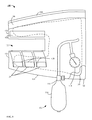
- FIG. 17 is a perspective view of a blood vessel access kit in an exemplary embodiment.
- FIG. 18 is a perspective view of a blood vessel access kit in an alternate exemplary embodiment.
- FIG. 19 is a partial cross-section elevation view of an alternate embodiment of the inventive exemplary embodiment of FIG. 5 .
- FIG. 20 is a partial cross-section elevation view of the alternate embodiment of FIG. 19 showing an advancement of a novel vacuum vile.
- FIG. 22 is a partial cross-section elevation view of the alternate embodiment of FIG. 19 showing a full retracted needle and separated novel vacuum vile of FIG. 21 .
- FIG. 23 is a partial cutaway top plan view of the blood channeling apparatus in an alternate exemplary embodiment.
- FIG. 24 is a partial cutaway bottom plan view of the alternate exemplary embodiment of the novel blood channeling apparatus of FIG. 23 .
- FIG. 25 is a flow diagram disclosing an exemplary method of using the inventive blood vessel access kit Step 1 through Step 9 and continuing to Step 10 .
- FIG. 26 is a flow diagram disclosing an exemplary method of using the inventive blood vessel access kit Step 10 through Step 12 , and continuing to step 13 or in the alternative Step 15 .
- FIG. 27 is a flow diagram disclosing an exemplary method of using the inventive blood vessel access kit Step 13 through Step 14 .
- FIG. 28 is a flow diagram disclosing an exemplary method of using the inventive blood vessel access kit Step 15 through Step 18 .
- FIG. 29 is a top plan view of an alternative alternate exemplary embodiment of a novel blood channeling apparatus, also referred to as a vein presentation enhancement device.
- FIG. 30 is a top plan view of a conduit interface member of the alternative alternate exemplary embodiment of the novel vein presentation enhancement device of FIG. 29 .
- FIG. 33 is a bottom plan view of the alternative alternate exemplary embodiment of the inventive vein presentation enhancement device of FIG. 29 .
- FIG. 34 is a top plan view of an extension member configured for use with the alternative alternate exemplary embodiment of the inventive vein presentation enhancement device of FIG. 29 .
- FIG. 35 is a bottom plan view of the extension member of FIG. 34 .
- FIG. 36 is a bottom plan view of the alternative alternate exemplary embodiment of the inventive vein presentation enhancement device of FIG. 29 .
- FIG. 37 is a flow diagram of a method of using the inventive vein presentation enhancement device of FIG. 29 for starting an IV.
- FIG. 38 is a flow diagram of an alternate method of using the inventive vein presentation enhancement device of FIG. 29 for drawing blood.
- FIG. 39 is a top plan view of another alternate exemplary embodiment of a novel blood channeling apparatus, also referred to as a vein presentation enhancement device.
- FIG. 40 is a bottom plan view of the novel blood channeling apparatus of FIG. 39 , also referred to as a vein presentation enhancement device.
- FIG. 41 is a top plan view of another alternative exemplary embodiment of a novel blood channeling apparatus, also referred to as a vein presentation enhancement device.
- FIG. 42 is a top plan view of another alternative exemplary embodiment of a novel blood channeling apparatus, also referred to as a vein presentation enhancement device.
- FIG. 43 is a bottom plan view of the novel blood channeling apparatus of FIG. 42 .
- FIG. 44 is a top plan view of a seal bag for a blood channeling apparatus.
- FIG. 45 is a bottom plan view of the seal bag of FIG. 44 .
- Exemplary embodiments of the present invention are generally directed to a blood vessel access kit configured to facilitate a transfer of fluids with a predetermined blood vessel.
- a blood vessel access kit configured to facilitate a transfer of fluids with a predetermined blood vessel.
- FIG. 1 shows an exemplary blood channeling apparatus 100 of an exemplary embodiment, also referred to herein as a vein presentation enhancement device 100 .
- the exemplary blood channeling apparatus 100 includes an interior cover 102 secured to an exterior cover 104 .
- the exterior cover 104 supports a first securement member 106 and a first fastening member 108 .
- a bladder 110 is disposed between the interior cover 102 and the exterior cover 104 .
- the bladder 110 serves to apply pressure to the extremity to encourage additional blood into a blood vessel of interest to accommodate the insertion of an intravenous (“IV”) catheter into the blood vessel of interest.
- IV intravenous
- an air transfer assembly 112 communicates with the bladder 110 .
- the air transfer assembly 112 includes at least an inflation mechanism 114 , which may be of a manual or mechanical type; a valve 116 , which selectively controls air flow into and out of the bladder 110 ; and a gauge 118 , which may be of an analog or digital type and is provided to alert the practitioner to the amount of pressure present in the bladder 110 .
- the interior cover 102 and exterior cover 104 join to form a plurality of projections 120 that define a window 122 .
- at least one attachment tab 124 is secured to one of the plurality of projections 120 and is configured for engagement with the first fastening member 108 secured to a corresponding projection 120 , of the plurality of projections 120 .
- FIG. 2 displays a bottom plan view of the exemplary blood channeling apparatus 100 of the exemplary embodiment.
- a second fastening member 126 is shown secured to the interior cover 102 of the exemplary blood channeling apparatus 100 .
- the second fastening member 126 of the interior cover 102 is preferably configured to connect to the first securement member 106 of the exterior cover 104 to allow the exemplary blood channeling apparatus 100 to surround an extremity of a patient.
- FIG. 3 shows a view of section A-A of the exemplary blood channeling apparatus 100 in an exemplary embodiment of FIG. 2 , indicative of a form consistent with the exemplary blood channeling apparatus 100 enclosing an appendage of a patient, at a distal end of a patient's appendage and adjacent an extremity of that appendage.
- the window 122 of the exemplary blood channeling apparatus 100 can accommodate various dimensional sizes by varying an amount of overlap of a second securement member 128 (secured to the attachment tab 124 ), relative to the first fastening member 108 as seen by FIG. 4 .
- first and second fastening members 108 , 126 are loop portions of a hook and loop fastening system, while the first and second securement members 106 , 128 are hook portions of a hook and loop fastening system. It is noted however that alternate fastening systems are contemplated, based on the specific use environment of the exemplary blood channeling apparatus 100 .
- the exemplary blood channeling apparatus 100 confines an extremity of a patient via the connection of the first securement member 106 and the second fastening member 126 .
- FIG. 4 shows a view of section B-B of the exemplary blood channeling apparatus 100 in an exemplary embodiment of FIG. 2 , indicative of a form consistent with the exemplary blood channeling apparatus 100 enclosing an appendage of a patient, at a distal end of a patient's appendage and adjacent an extremity of that appendage.
- the attachment tab 124 of the exemplary blood channeling apparatus 100 is shown preferably configured to size the window 122 .
- a plurality of attachment tabs 124 can be connected to their corresponding first fastening member 108 of projection 120 of the interior and exterior covers 102 and 104 , to provide several possible window sizes. Again, the size of the window 122 is determined by an amount of overlap of the second securement member 128 relative to the first fastening member 108 .
- FIG. 5 shows an exemplary intravenous catheter 200 , which preferably includes at least a fluid chamber 202 that provides at least one conduit 204 and diaphragm housing 206 .
- the diaphragm housing 206 is located on the proximal end of the fluid chamber 202 , and catheter 208 secured to the distal end of the fluid chamber 202 .
- a needleless valve 210 communicates with the fluid chamber 202 via a fluid transfer tube 211 secured to and disposed between the conduit 204 and the needleless valve 210 .
- the CLAVE® Connector with luer lock such as those manufactured by ICU Medical Inc. of San Clemente Calif., has been found to be suitable as the needless valve 210 .
- FIG. 5 further shows the fluid chamber 202 of the exemplary intravenous catheter 200 preferably has a securement member 212 adjacent the diaphragm housing 206 .
- a diaphragm 214 is confined in the diaphragm housing 206 , and is configured to allow passage of a hypodermic needle 216 , which extends from a needle transport 218 through the diaphragm 214 , the fluid chamber 202 , and the catheter 208 when the exemplary intravenous catheter 200 is configured for insertion into a predetermined blood vessel of a patient.
- the needle transport 218 includes a needle confinement feature 220 , which interacts with a needle safety catch feature 224 to secure the hypodermic needle 216 within a needle confinement housing 222 , once the hypodermic needle 216 has been extracted from the diaphragm 214 .
- FIG. 6 shows the needle transport 218 of the exemplary intravenous catheter 200 preferably includes a plurality of isolation diaphragms 226 configured to enclose first and second fluid ports 228 and 230 of the hypodermic needle 216 , when the needle confinement feature 220 is secured by the needle safety catch feature 224 . Further in an exemplary embodiment, a grip portion 232 is provided by the needle transport 218 to facilitate sliding communication of the needle transport 218 with the needle confinement housing 222 .
- FIG. 7 shows an exemplary syringe 300 in an exemplary embodiment.
- the exemplary syringe 300 preferably comprises a hollow cylinder 302 , shown in partial cut-away, which provides a support flange 304 on a proximal end of the hollow cylinder 302 .
- a piston 306 that includes at least a seal portion 308 positioned on a distal end and in sliding contact with an internal surface 310 (shown in FIG. 8 ) of the hollow cylinder 302 , a piston activation member 312 on a proximal end, and a stem 314 disposed between the seal portion 308 and the piston activation member 312 .
- the piston 306 selectively serves to draw fluids in and expel fluids from the hollow cylinder 302 .
- the stem provides a plurality of calibration notches 316 , which when positioned into alignment with a stem control member 318 , provided by the support flange 304 , controls transfer of a precise volume of fluid drawn in or expelled from the hollow cylinder 302 .
- FIG. 8 further shows the exemplary syringe 300 of an exemplary embodiment includes a tapered portion (also referred to herein as a luer) 320 and a securement member 322 at the distal end of the hollow cylinder 302 .
- the luer 320 and securement member 322 are at least configured to interact with a needleless valve 210 (of FIG. 5 ).
- FIG. 9 shows a top plan view of the hollow cylinder 302 of the exemplary syringe 300 in an exemplary embodiment.
- the stem control member 318 of the exemplary syringe 300 is preferably formed from a material, such as spring steel, but may be formed of any material that provides a spring like response, and is secured to, formed in or formed with the support flange 304 of the hollow cylinder 302 .
- the stem control member 318 interacts with the calibration notches 316 to control displacement of the piston 306 in the hollow cylinder 302 .
- FIG. 10 displays a bottom plan view of the piston 306 of the exemplary syringe 300 in an exemplary embodiment.
- the stem 314 of the exemplary syringe 300 preferably includes a plurality of fins 324 in which the calibration notches 316 are preferably located on at least two of the plurality of fins 324 , while at least one alternate fin 324 of the plurality of fins 324 provide a land 326 .
- the piston 306 is free to move unencumbered within the hollow cylinder 302 (of FIG. 8 ), having only the sliding friction developed between the seal portion 308 and the internal surface 310 (shown in FIG. 8 ) of the hollow cylinder 302 to overcome.
- FIG. 11 shows an exemplary container 400 of the exemplary embodiment that preferably includes at least a seal housing 402 supporting an access seal 404 , which prevents inadvertent access to the interior of the seal housing 402 .
- the seal housing 402 is secured to a diaphragm 406 (also referred to herein as an inline coupling 406 ), which preferably surrounds a portion of a test tube 408 to form a vacuum seal 407 with the test tube 408 and present a vacuum charged blood collection tube.
- a diaphragm 406 also referred to herein as an inline coupling 406
- FIG. 11A shows the seal housing 402 of the exemplary container 400 is operatively connectable to at least the needleless valve 210 preferably via luer lock threads 409 provided by the needleless valve 210 .
- the seal housing 402 is secured to a diaphragm 406 (also referred to herein as an inline coupling 406 ), which preferably surrounds a portion of the test tube 408 to present a vacuum blood collection tube.
- the inline coupling 406 of the exemplary container 400 forms a vacuum seal 407 with the test tube 408 .
- FIG. 12 displays the exemplary container 400 in an exemplary embodiment that includes a bidirectional tapered luer 410 secured within the seal housing 402 .
- the bidirectional tapered luer 410 is held in abutting adjacency against a resilient seal 412 by a plurality of retention fingers 414 , provided by the seal housing 402 , interacting with an annular retention collar 416 of the bidirectional tapered luer 410 .
- the seal housing 402 comprises a conduit 418 surrounded by the resilient seal 412 .
- the conduit 418 of the exemplary container 400 further preferably comprises a fluid access port 420 .
- the bidirectional tapered luer 410 interacts with a resilient seal 422 of the needleless valve 210 to expose a fluid port 424 of the needleless valve 210 in preparation for a transfer of fluid through a fluid tube 426 of the needleless valve 210 .
- the bidirectional tapered luer 410 interacts with the resilient seal 412 of the seal housing 402 to expose the fluid access port 420 of the conduit 418 , which exposes the vacuum environment within the test tube 408 to pull fluid from the fluid tube 426 into the test tube 408 .
- the exemplary container 400 is disengaged from the needleless valve 210 and the respective resilient seals 412 and 422 close off their respective fluid ports 420 and 424 .
- FIG. 13 shows the bidirectional tapered luer 410 of the exemplary container 400 (of FIG. 12 ) includes a first tapered end 428 , a second tapered end 430 , and a luer seating ridge 432 .
- a vacuum is drawn on the test tube 408 (of FIG. 12 ) via the fluid port 420 (of FIG. 12 ), then the bidirectional tapered luer 410 is positioned within the seal housing 402 (of FIG. 12 ) such that the retention fingers 414 engage the retention collar 416 , which positions the second tapered end 430 adjacent the resilient seal 412 (of FIG. 12 ) and confines the bidirectional tapered luer 410 within the seal housing 402 .
- the exemplary container 400 When the exemplary container 400 initially engages the needleless valve 210 (of FIG. 12 ), the first tapered end 428 of the bidirectional tapered luer 410 contacts the resilient seal 422 (of FIG. 12 ), and as the engagement of the exemplary container 400 with the needleless valve 210 progresses, the retention fingers 414 encounter the luer seating ridge 432 as shown by FIG. 14 .
- an amount of force required for the retention fingers 414 to pass by the luer seating ridge 432 is greater than the force needed to compress the resilient seal 422 of the needleless valve 210 , and the resilient seal 422 compresses to open the fluid port 424 (of FIG. 12 ).
- the first tapered end 428 of the bidirectional tapered luer 410 bottoms out against the housing of the needleless valve 210 ; that is the housing encapsulating the resilient seal 422 .
- the retention fingers 414 overcome the luer seating ridge 432 , and second tapered end 430 compresses the resilient seal 412 of the housing 402 , which opens the fluid port 420 of the housing 402 causing the vacuum within the test tube 408 to draw fluid from the fluid tube 426 into the test tube 408 .
- both the luer seating ridge 432 and the retention collar 416 provide a contoured bottom surface and a flat top surface. The contoured bottom surface accommodates passage of the retention fingers 414 by the luer seating ridge 432 and the retention collar 416 , while the flat top surfaces inhibit passage of the retention fingers 414 by the luer seating ridge 432 and the retention collar 416 .
- the bidirectional tapered luer 410 will remain confined within the housing 402 . Removal of the bidirectional tapered luer 410 from the housing 402 is accomplished by encouraging the retention fingers 414 away from the luer seating ridge 432 or the retention collar 416 as the case may be.
- FIGS. 17 and 18 show a perspective view of an exemplary blood vessel access kit 500 .
- the exemplary blood vessel access kit 500 preferably includes the exemplary blood channeling apparatus 100 engaging the appendage 502 of a patient.
- the air transfer assembly 112 is preferably displayed configured to supply air to the exemplary blood channeling apparatus 100 .
- a tourniquet 504 restricts venous blood flow of the patient.
- the exemplary intravenous catheter 200 is illustrated communicating with a blood vessel of the patient.
- the needle confinement housing 222 is preferably shown restricting the needle transport 218 .
- the exemplary syringe 300 or the exemplary container 400 is mutually distinct in the ability to transfer fluids from a blood vessel of the patient.
- FIG. 19 shows an alternate exemplary intravenous catheter 600 , which preferably includes at least a fluid chamber 202 that provides at least one conduit 204 and diaphragm housing 206 .
- the diaphragm housing 206 is located on the proximal end of the fluid chamber 202
- the catheter 208 is secured to the distal end of the fluid chamber 202 .
- a needleless valve 210 communicates with the fluid chamber 202 via a fluid transfer tube 211 secured to and disposed between the conduit 204 and the needleless valve 210 .
- the CLAVE® Connector with luer lock such as those manufactured by ICU Medical Inc. of San Clemente Calif., has been found to be suitable as the needleless valve 210 .
- FIG. 19 further shows the fluid chamber 202 of the alternate exemplary intravenous catheter 600 preferably has a securement member 212 adjacent the diaphragm housing 206 .
- the alternate exemplary intravenous catheter 600 includes a diaphragm 214 confined in the diaphragm housing 206 , and configured to allow passage of a hypodermic needle 216 , which extends from a needle transport 218 through the diaphragm 214 , the fluid chamber 202 , and the catheter 208 when the alternate exemplary intravenous catheter 600 is configured for insertion into a predetermined blood vessel of a patient.
- the needle transport 218 includes a needle confinement feature 220 , which interacts with a needle safety catch feature 224 to secure the hypodermic needle 216 within a needle confinement housing 602 , once the hypodermic needle 216 has been extracted from the diaphragm 214 .
- the alternate exemplary intravenous catheter 600 further includes an exemplary vacuum vessel assembly 604 fitted within and constrained by the needle confinement housing 602 through the use of a securement key 606 .
- the exemplary vacuum vessel assembly 604 may be advanced relative to the hypodermic needle 216 until the hypodermic needle 216 penetrates through a self-sealing diaphragm 608 fitted within a rigid test tube shaped vessel 610 .
- the rigid test tube shaped vessel 610 provides access to a vacuum environment provided by the exemplary vacuum vessel assembly 604 of the alternate exemplary intravenous catheter 600 .
- the exemplary vacuum vessel assembly 604 further provides an advancement tab assembly 612 , which interacts with a slide channel 614 provided by the needle confinement housing 602 of the alternate exemplary intravenous catheter 600 .
- FIG. 20 shows that as an advancement force is applied to the advancement tab assembly 612 of the exemplary vacuum vessel assembly 604 , the advancement tab assembly 612 progresses along the slide channel 614 .
- the progression of the advancement tab assembly 612 along the slide channel 614 imparts both a rotational motion and a lateral motion on the rigid test tube shaped vessel 610 relative to the hypodermic needle 216 .
- the collective motions of the rigid test tube shaped vessel 610 promote penetration of the self-sealing diaphragm 608 by the hypodermic needle 216 .
- FIG. 21 shows the advancement tab assembly 612 of the exemplary vacuum vessel assembly 604 in its maximum advancement position.
- the advancement tab assembly 612 is shown to include at least a slide shaft 616 , that interacts directly with the slide channel 614 , and an appendage platform 618 secured to the slide shaft 616 .
- the slide shaft 616 is positioned in a second slide channel, which accommodates the exodus of the exemplary vacuum vessel assembly 604 from the needle confinement housing 602 at the conclusion of the medical procedure.
- FIG. 22 shows the needle transport 218 of the alternate exemplary intravenous catheter 600 preferably includes a plurality of isolation diaphragms 226 configured to enclose first and second fluid ports 228 and 230 of the hypodermic needle 216 , when the needle confinement feature 220 is secured by the needle safety catch feature 224 . Further in an exemplary embodiment, a grip portion 232 is provided by the needle transport 218 to facilitate sliding communication of the needle transport 218 with the needle confinement housing 602 .
- FIG. 23 shows an alternative exemplary blood channeling apparatus 700 of an exemplary embodiment.
- the alternative exemplary blood channeling apparatus 700 includes an interior cover 702 secured to an exterior cover 704 .
- the exterior cover 704 supports a first securement member 106 and a first fastening member 108 .
- an air bladder is formed therebetween. The bladder serves to apply pressure to the extremity of a patient to encourage additional blood into a blood vessel of interest to accommodate the insertion of an intravenous (“IV”) catheter into the blood vessel of interest.
- IV intravenous
- an air transfer assembly 112 communicates with the formed bladder.
- the air transfer assembly 112 includes at least an inflation mechanism 114 , which may be of a manual or mechanical type; and a valve 116 , which selectively controls air flow into and out of the formed bladder.
- the interior cover 702 and exterior cover 704 join to form a plurality of projections 120 that define a window 122 .
- at least one attachment tab 124 is secured to one of the plurality of projections 120 and is configured for engagement with the first fastening member 108 secured to a corresponding projection 120 , of the plurality of projections 120 .
- FIG. 24 displays a bottom plan view of the alternative exemplary blood channeling apparatus 700 of the exemplary embodiment.
- a second fastening member 126 is shown secured to the interior cover 702 of the alternative exemplary blood channeling apparatus 700 .
- the second fastening member 126 of the interior cover 702 is preferably configured to connect to the first securement member 106 of the exterior cover 704 to allow the alternative exemplary blood channeling apparatus 700 to surround an extremity of a patient.
- FIG. 25 shows the exemplary process 800 to commence at process Step 1 , with the application of a tourniquet to a patient.
- process Step 2 prepare a needle for use.
- saline is advanced into the needle. Venipuncture is attempted at process Step 4 .
- process Step 5 create a vacuum in the needle and catheter apparatus.
- operator looks for a flash of blood into the catheter.
- process Step 7 A a flash of blood is observed.
- the needle is maneuvered until a flash of blood is observed (of process Step 7 A). After the flash of blood is observed (of process Step 7 A), the needle tip is held stationary while positioning the catheter in process Step 8 .
- process step 9 the catheter is advanced over the needle and into the punctured vein.
- Process Step 10 continues in FIG. 26 .
- process Step 10 A shows the catheter advances into the vein.
- process Step 10 B the catheter fails to advance easily and the operator maneuvers the catheter so that it will advance.
- Process Step 11 shows that proper placement of the advanced catheter (of process Step 10 A) can be verified once the catheter is advanced into the vein.
- process Step 12 A blood is withdrawn, and the exemplary process 800 continues at process Step 15 .
- process Step 12 B no withdraw or flash of blood is observed, so the catheter is repositioned, and the exemplary process 800 continues at process Step 13 in FIG. 27 .
- process Step 13 A shows catheter is repositioned after seeing a flash of blood and in process Step 14 A the catheter easily advances so the operator continues from process Step 11 (of FIG. 26 ), or in the alternative if the catheter resists advancement the operator may need to continue with process Step 10 B (of FIG. 26 ), process Step 3 (of FIG. 25 ), or process Step 1 (of FIG. 25 ).
- process Step 13 B no flash of blood is observed so the operator returns to process Step 7 B (of FIG. 25 ).
- process Step 15 shows infusion locking position is achieved and the tourniquet is removed.
- the needle is withdrawn into a safety shield.
- the safety shield is disposed of in a sharps container.
- the catheter is secured to the patient.
- FIG. 29 shows a top plan view of a preferred vein presentation enhancement device 820 , which includes at least an exterior cover 822 that provides a first securement member 824 supported by a web 826 .
- the web 826 is formed from a polyvinylchloride (“PVC”) material
- the first securement member 824 is the loop portion of a hook and loop fastening system formed from a polymer and adhered to the web 826 .
- FIG. 29 further shows that the exterior cover 822 preferably provides an access aperture 828 through which a conduit interface member 830 is feed-through from the back side and secured to the web 826 by a heat seal 832 .
- FIG. 29 is a preferred means of securing a preferred first fastening member 836 (shown by FIG. 33 ) to each an interior cover 838 (of FIG. 33 ), and the exterior cover 822 .
- the interior cover 838 provides a patient contact material 840 supported by a web 842 .
- the web 842 is formed from a PVC material; the patient contact material 840 is formed from cotton and adhered to the web 842 .
- the first fastening member 836 provided the hook portion of a hook and loop fastening system, and is formed from a polymer.
- the interior cover 838 is secured to the exterior cover 822 by a heat seal 844 and a plurality of strain relief features 846 .
- a preferred result of completion of the heat seal process is the formation of an air tight bladder 848 , and at least two projections 850 , which collectively define a blood access window 852 .
- the vein presentation enhancement device 820 is preferably configured such that when wrapped in secure contact around a limb of a patient with the first fastening member 836 secured to the first securement member 824 , upon inflating the bladder the first fastening member 836 will self release from the first securement member 824 at a pressure of about 195 to 220 mmHg, thereby mitigating an ill effect of overinflating the vein presentation enhancement device 820 .
- FIG. 34 shows a top plan view of a preferred extension member 854 for the vein presentation enhancement device 820 , which includes at least an exterior extension cover 856 that provides a second securement member 858 supported by an exterior extension web 860 .
- the exterior extension web 860 is formed from a PVC material
- the second securement member 858 is the loop portion of a hook and loop fastening system formed from a polymer and adhered to the exterior extension web 860 .
- the stitching 862 shown in FIG. 34 is a preferred means of securing a preferred second fastening member 866 (shown by FIG. 35 ) to each an interior extension cover 868 (of FIG. 35 ), and the exterior extension cover 856 .
- the interior extension cover 868 provides a patient contact extension material 870 supported by an interior extension web 872 .
- the interior extension web 872 is formed from a PVC material; the patient contact extension material 870 is formed from cotton and adhered to the interior extension web 872 .
- the second fastening member 866 provided the hook portion of a hook and loop fastening system, and is formed from a polymer.
- the interior extension cover 868 is secured to the exterior extension cover 856 by a heat seal 874 .
- FIG. 36 shows the preferred vein presentation enhancement device 820 secured to the preferred extension member 854 .
- the first fastening member 836 of the vein presentation enhancement device 820 provides the hook portion of a hook and loop fastening system
- the second securement member 858 of the extension member 854 provides the loop portion of the hook and loop fastening system.
- the result of adding the extension member 854 to the preferred vein presentation enhancement device 820 is an accommodation of various limbs, or portion of limbs, of patients.
- the inflatable tourniquet (vein presentation enhancement device 820 ) becomes functional by securing the second fastening member 866 (of FIG. 35 ) to the first securement member 836 (of FIG. 33 )
- FIG. 37 illustrates a flow diagram of a method of using the inventive vein presentation enhancement device 820 (of FIG. 29 ), in starting an IV in a patient
- FIG. 38 shows a flow diagram of an alternate method of using the inventive vein presentation enhancement device 820 of FIG. 29 in drawing blood from a patient.
- FIG. 39 shows a top plan view of a preferred vein presentation enhancement device 876 , which includes at least an exterior cover 878 that provides a first securement member 880 supported by a web 882 .
- the web 882 is formed from a polyvinylchloride (“PVC”) material
- the first securement member 880 is the loop portion of a hook and loop fastening system formed from a polymer and adhered to the web 882 .
- FIG. 39 further shows that the exterior cover 878 preferably provides an access aperture 884 through which a conduit interface member 830 (of FIGS. 30, 31, and 32 ) is feed-through from the back side of the exterior cover 878 and secured to the web 882 by a heat seal 886 .
- FIG. 39 is a preferred means of securing a preferred fastening member 890 (shown by FIG. 40 ) to each an interior cover 892 (of FIG. 40 ), and the exterior cover 878 .
- FIG. 39 further shows that heat seal 894 provides the external boundaries for each of the plurality of bladders, which in the present embodiment include, stage I bladder 896 , stage II bladder 898 , and stage III bladder 900 .
- Heat seal portion 902 forms the boundary and substantial fluidic seal between stage I bladder 896 and stage II bladder 898
- heat seal portion 904 forms the boundary and substantial fluidic seal between stage II bladder 898 and stage III bladder 900 .
- a first fluidic conduit 906 is provided to promote passage of fluid from stage I bladder 896 to stage II bladder 898 , once the volume and pressure of fluid in stage I bladder 896 reaches a predetermined level.
- a second fluidic conduit 908 is provided to promote passage of fluid from stage II bladder 898 to stage III bladder 900 , once the volume and pressure of fluid in stage II bladder 898 reaches a predetermined level.
- This substantial sequential inflation of bladders 896 , 898 , and 900 serve to encourage blood into veins accessible through the vein access window 910 , while mitigating blood flow away from the vein access window 910 .
- the interior cover 892 provides a patient contact material 912 supported by a web 914 .
- the web 914 is formed from a PVC material; the patient contact material 912 is formed from cotton and adhered to the web 914 .
- the fastening member 890 provided the hook portion of a hook and loop fastening system, and is formed from a polymer.
- the interior cover 892 is secured to the exterior cover 878 by the heat seal 894 and the heat seal portions 902 and 904 .
- a preferred result of completion of the heat seal process is the formation of bladders 896 , 898 , and 900 , which collectively define an air tight composite bladder 916 that includes and at least two projections 918 , which collectively define the blood access window 910 .
- FIG. 41 shows an exemplary embodiment in which the first fluidic conduit 906 is positioned near the mid portion of heat seal 902 , while the second fluidic conduit 908 is disposed adjacent opposite ends of heat seal 904 .
- the functionality of fluidic conduits 906 and 908 remain consistent with the explanation provided hereinabove.
- FIG. 42 is a top plan view of another alternative exemplary embodiment of a novel blood channeling apparatus 4200 , also referred to as a vein presentation enhancement device.
- the apparatus 4200 comprises a filling tube 4205 , a plurality of bladders 4210 , a plurality of bladder walls 4215 , a plurality of air passages 4220 , a perimeter seal 4225 , a blood access window 4230 , and hook and loop 4235 .
- the apparatus 4200 provides an improved structure that compresses the skin which directs the patient's blood towards the blood access window 4230 as the apparatus 4200 inflates.
- the filling tube (e.g., filling nipple) 4205 is configured to receive air from an inflation mechanism and inflate the apparatus 4200 .
- the air goes to a first bladder of the bladders 4210 , shown as a vertical strip on the right side of the embodiment of FIG. 42 .
- the first bladder is defined by the perimeter seal 4225 and one of the bladder walls 4215 , with one or more small air passages 4220 allowing a small amount of air to exit the first bladder and into a second bladder.
- the second bladder is adjacent to the first bladder, and is illustrated as being vertical and in parallel with the first bladder.
- the second bladder receives air through the air passages 4220 around the bladder walls 4215 .
- Additional bladders are adjacent to the second bladder, and receive air through the air passages 4220 .
- the additional bladders are illustrated as being smaller and vertical to each other.
- the air passages 4220 allow air to pass around the bladder walls 4215 .
- the air passages 4220 are designed and sized such that the first bladder fills up before the second bladder which is needed to compress the skin to start blood diversion and limit blood from returning away from the window as subsequent bladders inflate.
- the air passages 4220 are sized such that the second bladder fills up before the additional bladders continuing the directional blood diversion.
- the bladders fill up from right to left. This enables the bladders 4210 to push or divert the patient's blood towards the blood access window 4230 .
- the most important function of the Vein Presentation Enhancement Device is to increase the intravascular pressure of the vein by diverting blood from deeper tissues into the superficial veins and increasing the intravascular venous pressure in excess of traditional techniques such as the superficial tourniquet.
- the bladders 4210 are illustrated as being eight bladders, and described as being multiple bladders, one could instead referred to the bladders 4210 as one large bladder, since they are connected by the air passages 4220 . Additionally, the apparatus 4200 can have more or less than the illustrated amount of bladders 4210 , bladder walls 4215 , or air passages 4225 , while still pushing the patient's blood towards the blood access window 4230 .
- the perimeter seal 4225 can connect the inner and outer layers of the apparatus 4200 , acting like an additional set of bladder walls 4215 .
- the blood access window 4230 provides an opening for a medical professional to draw blood from a patient. Due to the inward pressure provided by the apparatus 4200 , the patient's vein can more easily be accessed.
- the hook and loop (e.g., velcro) 4235 provides an attachment means to the patient.
- the apparatus 4200 is manufactured by first welding together the perimeter seal's external and internal walls. This sealing can be performed by a radio frequency welding. Radio frequency welding is the process by which electromagnetic energy is used to permanently bond thermoplastic materials together. Next, the velcro 4235 is attached thereon. Lastly, the apparatus can be labeled with instructions or trademark information.
- FIG. 43 is a bottom plan view of the novel blood channeling apparatus 4200 of FIG. 42 .
- the bottom view illustration is the same as the top view but the filling nipple 4205 cannot be seen from the bottom.
- FIG. 44 is a top plan view of a seal bag 4400 for a blood channeling apparatus.
- the seal bag 4400 comprises a slit 4405 , a plurality of adhesive flaps 4410 , and a pull string or strings 4415 .
- the seal bag 4400 is a quick and easy way to remove the apparatus from the patient by separating the adhesive flaps 4410 from the body of the seal bag.
- the seal bag 4400 also makes it easier to spot a leak in the apparatus during use.
- the slit 4405 is sized such that an air tube can pass therethrough.
- the adhesive flaps 4410 attach the apparatus to the patient, and are configured to be ripped open by the string 4415 .
- the string 4415 is located underneath the adhesive flaps 4410 , and can be pulled by either end.
- two separate strings are used, one on the bottom to allow a patient's appendage to pass through before the apparatus is used, and one on the side to rip off after use.
- one long string is used instead of two strings.
- the apparatus After the blood is removed from a patient, the apparatus is basically torn open by pulling the string 4415 embedded in the adhesive flaps 4410 which will allow the apparatus to be removed.
- the seal bag 4400 is designed for a single use due to the breakaway nature of opening it.
- FIG. 45 is a bottom plan view of the seal bag of FIG. 44 .
- the bottom view illustration is the same as the top view except for the adhesive flaps are shown from the opposite side.
- the apparatus has an air tube entrance on the top and bottom of the apparatus. In another embodiment, the apparatus has only one air tube entrance.
Abstract
Preferably, an embodiment of a vein presentation enhancement device includes at least, an interior cover supporting a first fastening member, and an exterior cover communicating with the interior cover, wherein the exterior cover provides a first securement member that interacts with the first fastening member to secure the preferred device positioned about a limb of a subject. The preferred embodiment further includes a bladder formed between the interior and exterior covers, and an air transfer assembly connected to said bladder for transfer of air into and out of said bladder, wherein said interior and exterior covers collectively provide a plurality of projections defining a blood access window.
Description
This application is a continuation-in-part to U.S. patent application Ser. No. 13/478,945 filed May 23, 2012, which claims priority to a continuation-in-part to U.S. patent application Ser. No. 12/470,404 filed May 21, 2009, which claims priority to Provisional Patent Application Ser. No. 61/054,961 filed May 21, 2008.
The present invention relates generally to the interaction of fluids with a blood vessel, but not by way of limitation, to the field of medical equipment.
The ability to safely and efficiently interact fluids with blood vessels has been a continued need of the medical industry for generations.
Historically, the interaction of fluids with human blood vessels has been carried out through the conjunctive use of several fundamental medical instruments which are well known and in use by practitioners in the art. While these medical instruments reliably operate to interact with blood vessels, the safety and efficiency of using the instruments continues to pose a problem for the medical industry.
Accordingly, there is a continuing need for improved instruments and methods in the field of medical equipment.
In accordance with the exemplary embodiments, a preferred vein presentation enhancement device includes at least, an interior cover supporting a first fastening member, and an exterior cover communicating with the interior cover, wherein the exterior cover provides a first securement member that interacts with the first fastening member to secure the preferred device positioned about a limb of a subject. The preferred further includes a bladder formed between the interior and exterior covers, and an air transfer assembly connected to said bladder for transfer of air into and out of said bladder, wherein said interior and exterior covers collectively provide a plurality of projections defining a blood access window.
In an alternate preferred the vein presentation enhancement device is formed by steps that includes at least, providing an interior cover supporting a first fastening member, obtaining an exterior cover configured for communication with the interior cover, in which the exterior cover provides a first securement member, forming a bladder between said interior and exterior covers, and connecting an air transfer assembly to said bladder for transfer of air into and out of said bladder, wherein said interior and exterior covers collectively provide a plurality of projections defining a blood access window.
These and various other features and advantages which characterize the claimed invention will be apparent from reading the following detailed description and a review of the associated drawings.
Exemplary embodiments of the present invention are generally directed to a blood vessel access kit configured to facilitate a transfer of fluids with a predetermined blood vessel. Reference will now be made in detail to the presently exemplary embodiments of the invention, one or more examples of which are illustrated in the accompanying drawings. Each example is provided by way of explanation of the invention, not limitation of the invention. In fact, it will be apparent to those skilled in the art that various modifications and variations can be made in the present invention without departing from the scope or spirit of the invention. For example, features illustrated or described as part of one embodiment, can be used on another embodiment to yield a still further embodiment. Thus, it is intended that the present invention cover such modifications and variations as come within the scope of the appended claims and their equivalents. Additionally, the numbering of components in the drawings is consistent throughout the application, with the same components having the same number in each of the drawings.
To facilitate pressure build up and withdrawal, an air transfer assembly 112 communicates with the bladder 110. The air transfer assembly 112 includes at least an inflation mechanism 114, which may be of a manual or mechanical type; a valve 116, which selectively controls air flow into and out of the bladder 110; and a gauge 118, which may be of an analog or digital type and is provided to alert the practitioner to the amount of pressure present in the bladder 110.
In an exemplary embodiment, the interior cover 102 and exterior cover 104 join to form a plurality of projections 120 that define a window 122. In an exemplary embodiment, at least one attachment tab 124 is secured to one of the plurality of projections 120 and is configured for engagement with the first fastening member 108 secured to a corresponding projection 120, of the plurality of projections 120.
In an operative mode, upon an engagement of the needleless valve 210 by the exemplary container 400, the bidirectional tapered luer 410 interacts with a resilient seal 422 of the needleless valve 210 to expose a fluid port 424 of the needleless valve 210 in preparation for a transfer of fluid through a fluid tube 426 of the needleless valve 210. Upon further engagement of the exemplary container 400 with the needleless valve 210, the bidirectional tapered luer 410 interacts with the resilient seal 412 of the seal housing 402 to expose the fluid access port 420 of the conduit 418, which exposes the vacuum environment within the test tube 408 to pull fluid from the fluid tube 426 into the test tube 408. When pressure is equalized between the test tube 408 and the fluid tube 426, the exemplary container 400 is disengaged from the needleless valve 210 and the respective resilient seals 412 and 422 close off their respective fluid ports 420 and 424.
When the exemplary container 400 initially engages the needleless valve 210 (of FIG. 12 ), the first tapered end 428 of the bidirectional tapered luer 410 contacts the resilient seal 422 (of FIG. 12 ), and as the engagement of the exemplary container 400 with the needleless valve 210 progresses, the retention fingers 414 encounter the luer seating ridge 432 as shown by FIG. 14 . For exemplary embodiment 400, preferably an amount of force required for the retention fingers 414 to pass by the luer seating ridge 432 is greater than the force needed to compress the resilient seal 422 of the needleless valve 210, and the resilient seal 422 compresses to open the fluid port 424 (of FIG. 12 ).
With continued advancement of the exemplary container 400 onto the needleless valve 210, the first tapered end 428 of the bidirectional tapered luer 410 bottoms out against the housing of the needleless valve 210; that is the housing encapsulating the resilient seal 422. With further advancement of the exemplary container 400 onto the needleless valve 210, the retention fingers 414 overcome the luer seating ridge 432, and second tapered end 430 compresses the resilient seal 412 of the housing 402, which opens the fluid port 420 of the housing 402 causing the vacuum within the test tube 408 to draw fluid from the fluid tube 426 into the test tube 408.
During fluid transfer, the retention fingers 414 are positioned, relative to the bidirectional tapered luer 410 as shown in FIG. 15 , and upon disengagement of the exemplary container 400 from the needleless valve 210, the retention fingers 414 engage a top side of the luer seating ridge 432, as shown by FIG. 16 . In an exemplary embodiment, both the luer seating ridge 432 and the retention collar 416 provide a contoured bottom surface and a flat top surface. The contoured bottom surface accommodates passage of the retention fingers 414 by the luer seating ridge 432 and the retention collar 416, while the flat top surfaces inhibit passage of the retention fingers 414 by the luer seating ridge 432 and the retention collar 416. Accordingly, when the retention fingers 414 are adjacent the flat surfaces, of either the luer seating ridge 432 or the retention collar 416, the bidirectional tapered luer 410 will remain confined within the housing 402. Removal of the bidirectional tapered luer 410 from the housing 402 is accomplished by encouraging the retention fingers 414 away from the luer seating ridge 432 or the retention collar 416 as the case may be.
The alternate exemplary intravenous catheter 600 further includes an exemplary vacuum vessel assembly 604 fitted within and constrained by the needle confinement housing 602 through the use of a securement key 606. Upon removal of the securement key 606, the exemplary vacuum vessel assembly 604 may be advanced relative to the hypodermic needle 216 until the hypodermic needle 216 penetrates through a self-sealing diaphragm 608 fitted within a rigid test tube shaped vessel 610.
The rigid test tube shaped vessel 610 provides access to a vacuum environment provided by the exemplary vacuum vessel assembly 604 of the alternate exemplary intravenous catheter 600. To advance the rigid test tube shaped vessel 610, the exemplary vacuum vessel assembly 604 further provides an advancement tab assembly 612, which interacts with a slide channel 614 provided by the needle confinement housing 602 of the alternate exemplary intravenous catheter 600.
To facilitate pressure build up and withdrawal, an air transfer assembly 112 communicates with the formed bladder. The air transfer assembly 112 includes at least an inflation mechanism 114, which may be of a manual or mechanical type; and a valve 116, which selectively controls air flow into and out of the formed bladder.
In an exemplary embodiment, the interior cover 702 and exterior cover 704 join to form a plurality of projections 120 that define a window 122. In an exemplary embodiment, at least one attachment tab 124 is secured to one of the plurality of projections 120 and is configured for engagement with the first fastening member 108 secured to a corresponding projection 120, of the plurality of projections 120.
The flow charts, FIGS. 25 through 28 , disclose an exemplary method of using the inventive blood vessel access kit. FIG. 25 shows the exemplary process 800 to commence at process Step 1, with the application of a tourniquet to a patient. At process Step 2, prepare a needle for use. At process Step 3, saline is advanced into the needle. Venipuncture is attempted at process Step 4. In process Step 5, create a vacuum in the needle and catheter apparatus. At process Step 6, operator looks for a flash of blood into the catheter. In process Step 7 A, a flash of blood is observed. In the alternative, in process Step 7 B, the needle is maneuvered until a flash of blood is observed (of process Step 7 A). After the flash of blood is observed (of process Step 7 A), the needle tip is held stationary while positioning the catheter in process Step 8. In process step 9, the catheter is advanced over the needle and into the punctured vein. Process Step 10 continues in FIG. 26 .
In FIG. 26 , process Step 10 A shows the catheter advances into the vein. In the alternative, in process Step 10 B, the catheter fails to advance easily and the operator maneuvers the catheter so that it will advance. Process Step 11 shows that proper placement of the advanced catheter (of process Step 10 A) can be verified once the catheter is advanced into the vein. In process Step 12 A, blood is withdrawn, and the exemplary process 800 continues at process Step 15. In the alternative, in process Step 12 B, no withdraw or flash of blood is observed, so the catheter is repositioned, and the exemplary process 800 continues at process Step 13 in FIG. 27 .
In FIG. 27 , process Step 13 A shows catheter is repositioned after seeing a flash of blood and in process Step 14 A the catheter easily advances so the operator continues from process Step 11 (of FIG. 26 ), or in the alternative if the catheter resists advancement the operator may need to continue with process Step 10 B (of FIG. 26 ), process Step 3 (of FIG. 25 ), or process Step 1 (of FIG. 25 ). In the alternative, in process Step 13 B, no flash of blood is observed so the operator returns to process Step 7 B (of FIG. 25 ).
In FIG. 28 , process Step 15 shows infusion locking position is achieved and the tourniquet is removed. At process Step 16, the needle is withdrawn into a safety shield. In process Step 17, the safety shield is disposed of in a sharps container. At process Step 18, the catheter is secured to the patient.
While the process Steps of exemplary process 800 are meant to be exemplary, numerous changes to the Steps, and also the sequencing of the Steps, may be made which will readily suggest themselves to those skilled in the art and which are encompassed by the appended claims.
As further shown by FIG. 33 , the interior cover 838 provides a patient contact material 840 supported by a web 842. In a preferred embodiment, the web 842 is formed from a PVC material; the patient contact material 840 is formed from cotton and adhered to the web 842. Preferably, the first fastening member 836 provided the hook portion of a hook and loop fastening system, and is formed from a polymer. In a preferred embodiment, the interior cover 838 is secured to the exterior cover 822 by a heat seal 844 and a plurality of strain relief features 846. A preferred result of completion of the heat seal process is the formation of an air tight bladder 848, and at least two projections 850, which collectively define a blood access window 852.
The vein presentation enhancement device 820, is preferably configured such that when wrapped in secure contact around a limb of a patient with the first fastening member 836 secured to the first securement member 824, upon inflating the bladder the first fastening member 836 will self release from the first securement member 824 at a pressure of about 195 to 220 mmHg, thereby mitigating an ill effect of overinflating the vein presentation enhancement device 820.
As further shown by FIG. 35 , the interior extension cover 868 provides a patient contact extension material 870 supported by an interior extension web 872. In a preferred embodiment, the interior extension web 872 is formed from a PVC material; the patient contact extension material 870 is formed from cotton and adhered to the interior extension web 872. Preferably, the second fastening member 866 provided the hook portion of a hook and loop fastening system, and is formed from a polymer. In a preferred embodiment, the interior extension cover 868 is secured to the exterior extension cover 856 by a heat seal 874.
As further shown by FIG. 40 , the interior cover 892 provides a patient contact material 912 supported by a web 914. In a preferred embodiment, the web 914 is formed from a PVC material; the patient contact material 912 is formed from cotton and adhered to the web 914. Preferably, the fastening member 890 provided the hook portion of a hook and loop fastening system, and is formed from a polymer. In a preferred embodiment, the interior cover 892 is secured to the exterior cover 878 by the heat seal 894 and the heat seal portions 902 and 904. A preferred result of completion of the heat seal process is the formation of bladders 896, 898, and 900, which collectively define an air tight composite bladder 916 that includes and at least two projections 918, which collectively define the blood access window 910.
The filling tube (e.g., filling nipple) 4205 is configured to receive air from an inflation mechanism and inflate the apparatus 4200. Initially, the air goes to a first bladder of the bladders 4210, shown as a vertical strip on the right side of the embodiment of FIG. 42 . The first bladder is defined by the perimeter seal 4225 and one of the bladder walls 4215, with one or more small air passages 4220 allowing a small amount of air to exit the first bladder and into a second bladder. The second bladder is adjacent to the first bladder, and is illustrated as being vertical and in parallel with the first bladder. The second bladder receives air through the air passages 4220 around the bladder walls 4215. Additional bladders are adjacent to the second bladder, and receive air through the air passages 4220. The additional bladders are illustrated as being smaller and vertical to each other.
The air passages 4220 allow air to pass around the bladder walls 4215. The air passages 4220 are designed and sized such that the first bladder fills up before the second bladder which is needed to compress the skin to start blood diversion and limit blood from returning away from the window as subsequent bladders inflate. Similarly, the air passages 4220 are sized such that the second bladder fills up before the additional bladders continuing the directional blood diversion. As illustrated, the bladders fill up from right to left. This enables the bladders 4210 to push or divert the patient's blood towards the blood access window 4230. This advantageously provides an improved way of drawing blood by increasing the intravascular pressure of the vein. The most important function of the Vein Presentation Enhancement Device, in one embodiment, is to increase the intravascular pressure of the vein by diverting blood from deeper tissues into the superficial veins and increasing the intravascular venous pressure in excess of traditional techniques such as the superficial tourniquet.
Although the bladders 4210 are illustrated as being eight bladders, and described as being multiple bladders, one could instead referred to the bladders 4210 as one large bladder, since they are connected by the air passages 4220. Additionally, the apparatus 4200 can have more or less than the illustrated amount of bladders 4210, bladder walls 4215, or air passages 4225, while still pushing the patient's blood towards the blood access window 4230.
The perimeter seal 4225 can connect the inner and outer layers of the apparatus 4200, acting like an additional set of bladder walls 4215. The blood access window 4230 provides an opening for a medical professional to draw blood from a patient. Due to the inward pressure provided by the apparatus 4200, the patient's vein can more easily be accessed. The hook and loop (e.g., velcro) 4235 provides an attachment means to the patient.
In one embodiment, the apparatus 4200 is manufactured by first welding together the perimeter seal's external and internal walls. This sealing can be performed by a radio frequency welding. Radio frequency welding is the process by which electromagnetic energy is used to permanently bond thermoplastic materials together. Next, the velcro 4235 is attached thereon. Lastly, the apparatus can be labeled with instructions or trademark information.
The slit 4405 is sized such that an air tube can pass therethrough. The adhesive flaps 4410 attach the apparatus to the patient, and are configured to be ripped open by the string 4415.
The string 4415 is located underneath the adhesive flaps 4410, and can be pulled by either end. In one embodiment, two separate strings are used, one on the bottom to allow a patient's appendage to pass through before the apparatus is used, and one on the side to rip off after use. In another embodiment, one long string is used instead of two strings.
After the blood is removed from a patient, the apparatus is basically torn open by pulling the string 4415 embedded in the adhesive flaps 4410 which will allow the apparatus to be removed. The seal bag 4400 is designed for a single use due to the breakaway nature of opening it.
It will be clear that the present invention is well adapted to attain the ends and advantages mentioned as well as those inherent therein. While presently exemplary embodiments have been described for purposes of this disclosure, numerous changes may be made which will readily suggest themselves to those skilled in the art and which are encompassed by the appended claims.
Claims (4)
1. A vein presentation enhancement apparatus comprising:
an interior cover and an exterior cover, wherein the interior cover and the exterior cover are secured to one another to form a cuff, the interior cover including a first fastening member at a first end of the cuff, the exterior cover including a second fastening member at a second end of the cuff opposite to the first end of the cuff, and the first fastening member and the second fastening member are configured to removably attach to one another to wrap the cuff around a limb of a patient, wherein the first fastening member and the second fastening member are a respective hook portion and a respective loop portion of a hook and loop fastening system;
an air transfer assembly;
a blood access window configured to allow access to draw blood;
a plurality of bladder walls;
a plurality of bladders formed between the bladder walls, the plurality of bladders comprising a first bladder and a second bladder, wherein at least a portion of the first bladder is further from the blood access window than the second bladder;
a first air passage connecting the first bladder to the second bladder, wherein the first air passage is configured to apply air pressure to the first bladder before the second bladder;
a third bladder, the third bladder comprising at least one of the bladder walls; and
a second air passage connecting the second bladder to the third bladder, wherein the third bladder is adjacent to at least three sides of the blood access window and configured to apply air pressure to the second bladder before the third bladder.
2. The vein presentation enhancement apparatus of claim 1 further comprising a filling nipple configured to receive air from the air transfer assembly.
3. The vein presentation enhancement apparatus of claim 1 further comprising a perimeter seal for retaining the air within the vein presentation enhancement apparatus.
4. The vein presentation enhancement apparatus of claim 1 further comprising a seal bag, wherein the seal bag is configured to rip away from a patient using a pull string.
Priority Applications (1)
| Application Number | Priority Date | Filing Date | Title |
|---|---|---|---|
| US13/844,376 US9788773B2 (en) | 2008-05-21 | 2013-03-15 | Vein presentation enhancement device |
Applications Claiming Priority (4)
| Application Number | Priority Date | Filing Date | Title |
|---|---|---|---|
| US5496108P | 2008-05-21 | 2008-05-21 | |
| US47040409A | 2009-05-21 | 2009-05-21 | |
| US13/478,945 US9113894B2 (en) | 2008-05-21 | 2012-05-23 | Vein presentation enhancement device |
| US13/844,376 US9788773B2 (en) | 2008-05-21 | 2013-03-15 | Vein presentation enhancement device |
Related Parent Applications (1)
| Application Number | Title | Priority Date | Filing Date |
|---|---|---|---|
| US13/478,945 Continuation-In-Part US9113894B2 (en) | 2008-05-21 | 2012-05-23 | Vein presentation enhancement device |
Publications (2)
| Publication Number | Publication Date |
|---|---|
| US20130317538A1 US20130317538A1 (en) | 2013-11-28 |
| US9788773B2 true US9788773B2 (en) | 2017-10-17 |
Family
ID=49622185
Family Applications (1)
| Application Number | Title | Priority Date | Filing Date |
|---|---|---|---|
| US13/844,376 Active 2030-01-22 US9788773B2 (en) | 2008-05-21 | 2013-03-15 | Vein presentation enhancement device |
Country Status (1)
| Country | Link |
|---|---|
| US (1) | US9788773B2 (en) |
Citations (74)
| Publication number | Priority date | Publication date | Assignee | Title |
|---|---|---|---|---|
| US3161891A (en) | 1963-12-12 | 1964-12-22 | Ralph M Bauman | Portable urine specimen collecting device |
| US3413970A (en) | 1967-04-27 | 1968-12-03 | Paul E. Rockwell | Accessory instrument for the measurement of central venous pressure |
| US3625654A (en) | 1970-05-22 | 1971-12-07 | Charles M Van Duyne | Urine collection device |
| US3811136A (en) | 1972-09-06 | 1974-05-21 | Whitney Corp W | Sanitary urine collector |
| US3832738A (en) | 1973-09-13 | 1974-09-03 | Kleen Test Prod Inc | Mid-stream urine collector |
| US3844272A (en) | 1969-02-14 | 1974-10-29 | A Banko | Surgical instruments |
| US3955558A (en) | 1974-11-04 | 1976-05-11 | Medcom, Inc. | Instrument for spinal taps |
| US4106490A (en) | 1976-09-27 | 1978-08-15 | Raymond Spilman | Urine collection aid |
| US4143853A (en) | 1977-07-14 | 1979-03-13 | Metatech Corporation | Valve for use with a catheter or the like |
| US4297081A (en) | 1979-11-05 | 1981-10-27 | Irvin William A | Liquid level control system |
| US4299705A (en) | 1979-09-07 | 1981-11-10 | Russell Richard T | Method of treating blood during operative procedures |
| US4335730A (en) | 1979-08-30 | 1982-06-22 | Griffin Gladys B | Collector assembly and specimen tube therefor |
| US4664651A (en) | 1985-03-01 | 1987-05-12 | The Procter & Gamble Company | Subatmospheric method and apparatus for expanding blood vessels to facilitate puncture with a cannula |
| US4673393A (en) | 1984-12-28 | 1987-06-16 | Terumo Kabushiki Kaisha | Medical instrument |
| US4834802A (en) | 1987-08-06 | 1989-05-30 | Prier David A | Heat generating tourniquet for venipuncture applications |
| US4842591A (en) | 1988-01-21 | 1989-06-27 | Luther Ronald B | Connector with one-way septum valve, and assembly |
| US4895565A (en) | 1987-09-21 | 1990-01-23 | Cordis Corporation | Medical instrument valve |
| US4920971A (en) | 1988-12-09 | 1990-05-01 | Blessinger Martin W | Pneumatic vein inflation device |
| US4966588A (en) | 1986-07-25 | 1990-10-30 | H. G. Wallace Limited | Device suitable for the administration of a therapeutic substance |
| US5012818A (en) | 1989-05-04 | 1991-05-07 | Joishy Suresh K | Two in one bone marrow surgical needle |
| US5022385A (en) | 1989-11-02 | 1991-06-11 | Harza Richard D | Ergonomic anti-fatigue seating device and method |
| US5085645A (en) | 1990-08-15 | 1992-02-04 | Becton, Dickinson And Company | Apparatus and method for a catheter adapter with valve |
| US5199948A (en) | 1991-05-02 | 1993-04-06 | Mcgaw, Inc. | Needleless valve |
| US5201742A (en) | 1991-04-16 | 1993-04-13 | Hasson Harrith M | Support jig for a surgical instrument |
| US5295658A (en) | 1987-04-27 | 1994-03-22 | Vernay Laboratories, Inc. | Medical coupling site including slit reinforcing members |
| US5308352A (en) | 1989-11-17 | 1994-05-03 | Koutrouvelis Panos G | Stereotactic device |
| US5322516A (en) | 1993-05-20 | 1994-06-21 | Cobe Laboratories, Inc. | Safety needle system and method for using the same |
| US5380295A (en) | 1992-12-14 | 1995-01-10 | Mallinckrodt Medical, Inc. | Delivery apparatus with mechanism preventing rearward movement of a piston disposed therein |
| US5422076A (en) | 1991-03-11 | 1995-06-06 | Jones; R. Shane | Combined urine specimen bottle and cap |
| US5441487A (en) | 1993-11-30 | 1995-08-15 | Medex, Inc. | Plastic needleless valve housing for standard male luer locks |
| US5460427A (en) | 1990-10-29 | 1995-10-24 | Serber; Hector | Seat assembly and method |
| US5678891A (en) | 1995-11-14 | 1997-10-21 | Peter W. Linley | Dynamic combination seating and backrest support system |
| US5685864A (en) | 1993-11-22 | 1997-11-11 | Interventional Research Technologies | Locking device for aspirator, syringe or like instrument |
| US5784807A (en) * | 1995-09-18 | 1998-07-28 | Pagel; Todd A. | Fluid filled support system for footwear |
| US5843046A (en) | 1997-05-29 | 1998-12-01 | Paul J. Motisi | Catheter apparatus |
| WO1998055072A2 (en) | 1997-06-02 | 1998-12-10 | Vnus Medical Technologies, Inc. | Pressure tourniquet with ultrasound window |
| US5848966A (en) | 1997-03-04 | 1998-12-15 | Graphic Controls Corporation | Medical device easily removed from skin and a method of removal therefrom |
| US5876359A (en) * | 1994-11-14 | 1999-03-02 | Bock; Malcolm G. | Sequential compression device controller |
| US5910135A (en) | 1997-03-31 | 1999-06-08 | Innovative Design Associates | Intravenous infusion system |
| US5988946A (en) * | 1998-05-27 | 1999-11-23 | Reed; Charles | Multiple bladder flood control system |
| US6299606B1 (en) | 1999-03-16 | 2001-10-09 | Michael J. Young | Urine collection device |
| USD456898S1 (en) | 2001-06-18 | 2002-05-07 | Hsuan Yang | Disposable female urine sample cup holder |
| US6409971B1 (en) | 1999-08-06 | 2002-06-25 | Becton, Dickinson And Company | Device and method for collecting and transferring a urine specimen |
| US20020147431A1 (en) | 1996-12-16 | 2002-10-10 | Lopez George A. | Positive flow valve |
| US20020179794A1 (en) | 2001-05-30 | 2002-12-05 | Hsuan Yang | Disposable female urine sample cup holder for hospital use |
| US20030032905A1 (en) * | 1997-04-11 | 2003-02-13 | Waldridge Irene A. | Lymphedema treatment system |
| US20030078674A1 (en) * | 2001-07-26 | 2003-04-24 | Phillips Van L. | Socket insert having a bladder system |
| US20030098430A1 (en) | 2001-11-29 | 2003-05-29 | Leinsing Karl R. | Needle free medical connector with expanded valve mechanism and method of fluid flow control |
| US20030144691A1 (en) | 2002-01-31 | 2003-07-31 | Arnon Lambroza | Inflatable tourniquet |
| US6651259B1 (en) | 2002-05-31 | 2003-11-25 | Marlene D. Hartman | Urine specimen container system |
| US20040003517A1 (en) * | 2002-07-02 | 2004-01-08 | William Marvin | Shoe having an inflatable bladder |
| US6706007B2 (en) | 2000-12-29 | 2004-03-16 | Chf Solutions, Inc. | Feedback control of ultrafiltration to prevent hypotension |
| US20040097816A1 (en) | 2002-11-12 | 2004-05-20 | Steven Just | Blood pressure cuffs with resilient support sleeves |
| US6755391B2 (en) | 2000-10-23 | 2004-06-29 | Nypro Inc. | Anti-drawback medical valve |
| US6761715B2 (en) | 2001-04-26 | 2004-07-13 | Ronald J. Carroll | Method and device for neurocryo analgesia and anesthesia |
| US6840501B2 (en) | 1997-09-15 | 2005-01-11 | Alaris Medical Systems, Inc. | Needleless valve |
| US20050020977A1 (en) | 2003-07-25 | 2005-01-27 | Alba Innovations, Inc. | Intravascular infusion site anti-tamper guard having means for site inspection |
| US6908441B1 (en) | 2002-09-27 | 2005-06-21 | Clifford Bernard | Urine collection device |
| US20050189257A1 (en) * | 2004-03-01 | 2005-09-01 | Camry Packing Industrial Limited | Air packing bag having film-type check valves |
| US6946183B2 (en) | 2000-11-21 | 2005-09-20 | The Millennium Mat Company, Llc | Slip resistant mat |
| US7004961B2 (en) | 2003-01-09 | 2006-02-28 | Edward Wong | Medical device and method for temperature control and treatment of the brain and spinal cord |
| US20060122458A1 (en) | 2004-10-15 | 2006-06-08 | Baxano, Inc. | Devices and methods for tissue access |
| US20060149164A1 (en) | 2002-07-26 | 2006-07-06 | Lee Helen H | Liquid sampler and method |
| US20060184064A1 (en) | 2003-04-14 | 2006-08-17 | Sample Rite, Inc. | Urine sample collection device |
| US20070203455A1 (en) | 1999-04-26 | 2007-08-30 | Boston Scientific Scimed, Inc. | Apparatus and methods for guiding a needle |
| US20070219580A1 (en) | 2006-03-20 | 2007-09-20 | Mcewen James A | Low-cost contour cuff for surgical tourniquet systems |
| US20070282230A1 (en) * | 2005-12-15 | 2007-12-06 | Djo, Llc | Systems and methods for applying reversed sequence pressure to control edema flow |
| US20080249501A1 (en) | 2007-04-09 | 2008-10-09 | Medtronic Vascular, Inc. | Methods for Simultaneous Injection and Aspiration of Fluids During a Medical Procedure |
| US20080249467A1 (en) | 2007-04-05 | 2008-10-09 | Daniel Rogers Burnett | Device and Method for Safe Access to a Body Cavity |
| US20090240191A1 (en) | 2007-11-07 | 2009-09-24 | Aoti, Inc. | Pressure compensating seal with positive feedback |
| US7663502B2 (en) | 1992-05-05 | 2010-02-16 | Intelligent Technologies International, Inc. | Asset system control arrangement and method |
| US7703152B2 (en) | 2005-05-23 | 2010-04-27 | Carrol Leon Rhodes | Head and neck restraint system |
| US20100120306A1 (en) * | 2006-05-23 | 2010-05-13 | Malcom Adam J | Personal floatation device having selectively inflatable bladders |
| US20130238013A1 (en) | 2008-05-21 | 2013-09-12 | Robert J. Perry | Vein presentation enhancement device |
-
2013
- 2013-03-15 US US13/844,376 patent/US9788773B2/en active Active
Patent Citations (78)
| Publication number | Priority date | Publication date | Assignee | Title |
|---|---|---|---|---|
| US3161891A (en) | 1963-12-12 | 1964-12-22 | Ralph M Bauman | Portable urine specimen collecting device |
| US3413970A (en) | 1967-04-27 | 1968-12-03 | Paul E. Rockwell | Accessory instrument for the measurement of central venous pressure |
| US3844272A (en) | 1969-02-14 | 1974-10-29 | A Banko | Surgical instruments |
| US3625654A (en) | 1970-05-22 | 1971-12-07 | Charles M Van Duyne | Urine collection device |
| US3811136A (en) | 1972-09-06 | 1974-05-21 | Whitney Corp W | Sanitary urine collector |
| US3832738A (en) | 1973-09-13 | 1974-09-03 | Kleen Test Prod Inc | Mid-stream urine collector |
| US3955558A (en) | 1974-11-04 | 1976-05-11 | Medcom, Inc. | Instrument for spinal taps |
| US4106490A (en) | 1976-09-27 | 1978-08-15 | Raymond Spilman | Urine collection aid |
| US4143853A (en) | 1977-07-14 | 1979-03-13 | Metatech Corporation | Valve for use with a catheter or the like |
| US4335730A (en) | 1979-08-30 | 1982-06-22 | Griffin Gladys B | Collector assembly and specimen tube therefor |
| US4299705A (en) | 1979-09-07 | 1981-11-10 | Russell Richard T | Method of treating blood during operative procedures |
| US4297081A (en) | 1979-11-05 | 1981-10-27 | Irvin William A | Liquid level control system |
| US4673393A (en) | 1984-12-28 | 1987-06-16 | Terumo Kabushiki Kaisha | Medical instrument |
| US4664651A (en) | 1985-03-01 | 1987-05-12 | The Procter & Gamble Company | Subatmospheric method and apparatus for expanding blood vessels to facilitate puncture with a cannula |
| US4966588A (en) | 1986-07-25 | 1990-10-30 | H. G. Wallace Limited | Device suitable for the administration of a therapeutic substance |
| US5295658A (en) | 1987-04-27 | 1994-03-22 | Vernay Laboratories, Inc. | Medical coupling site including slit reinforcing members |
| US4834802A (en) | 1987-08-06 | 1989-05-30 | Prier David A | Heat generating tourniquet for venipuncture applications |
| US4895565A (en) | 1987-09-21 | 1990-01-23 | Cordis Corporation | Medical instrument valve |
| US4842591A (en) | 1988-01-21 | 1989-06-27 | Luther Ronald B | Connector with one-way septum valve, and assembly |
| US4920971A (en) | 1988-12-09 | 1990-05-01 | Blessinger Martin W | Pneumatic vein inflation device |
| US5012818A (en) | 1989-05-04 | 1991-05-07 | Joishy Suresh K | Two in one bone marrow surgical needle |
| US5022385A (en) | 1989-11-02 | 1991-06-11 | Harza Richard D | Ergonomic anti-fatigue seating device and method |
| US5022385B1 (en) | 1989-11-02 | 1999-06-22 | Richard D Harza | Ergonomic anti-fatigue seating device and method |
| US5308352A (en) | 1989-11-17 | 1994-05-03 | Koutrouvelis Panos G | Stereotactic device |
| US5085645A (en) | 1990-08-15 | 1992-02-04 | Becton, Dickinson And Company | Apparatus and method for a catheter adapter with valve |
| US5460427A (en) | 1990-10-29 | 1995-10-24 | Serber; Hector | Seat assembly and method |
| US5422076A (en) | 1991-03-11 | 1995-06-06 | Jones; R. Shane | Combined urine specimen bottle and cap |
| US5201742A (en) | 1991-04-16 | 1993-04-13 | Hasson Harrith M | Support jig for a surgical instrument |
| US5199948A (en) | 1991-05-02 | 1993-04-06 | Mcgaw, Inc. | Needleless valve |
| US7663502B2 (en) | 1992-05-05 | 2010-02-16 | Intelligent Technologies International, Inc. | Asset system control arrangement and method |
| US5380295A (en) | 1992-12-14 | 1995-01-10 | Mallinckrodt Medical, Inc. | Delivery apparatus with mechanism preventing rearward movement of a piston disposed therein |
| US5322516A (en) | 1993-05-20 | 1994-06-21 | Cobe Laboratories, Inc. | Safety needle system and method for using the same |
| US5685864A (en) | 1993-11-22 | 1997-11-11 | Interventional Research Technologies | Locking device for aspirator, syringe or like instrument |
| US5441487A (en) | 1993-11-30 | 1995-08-15 | Medex, Inc. | Plastic needleless valve housing for standard male luer locks |
| US5876359A (en) * | 1994-11-14 | 1999-03-02 | Bock; Malcolm G. | Sequential compression device controller |
| US5784807A (en) * | 1995-09-18 | 1998-07-28 | Pagel; Todd A. | Fluid filled support system for footwear |
| US5678891A (en) | 1995-11-14 | 1997-10-21 | Peter W. Linley | Dynamic combination seating and backrest support system |
| US20020147431A1 (en) | 1996-12-16 | 2002-10-10 | Lopez George A. | Positive flow valve |
| US5848966A (en) | 1997-03-04 | 1998-12-15 | Graphic Controls Corporation | Medical device easily removed from skin and a method of removal therefrom |
| US5910135A (en) | 1997-03-31 | 1999-06-08 | Innovative Design Associates | Intravenous infusion system |
| US20030032905A1 (en) * | 1997-04-11 | 2003-02-13 | Waldridge Irene A. | Lymphedema treatment system |
| US5843046A (en) | 1997-05-29 | 1998-12-01 | Paul J. Motisi | Catheter apparatus |
| WO1998055072A2 (en) | 1997-06-02 | 1998-12-10 | Vnus Medical Technologies, Inc. | Pressure tourniquet with ultrasound window |
| US6840501B2 (en) | 1997-09-15 | 2005-01-11 | Alaris Medical Systems, Inc. | Needleless valve |
| US5988946A (en) * | 1998-05-27 | 1999-11-23 | Reed; Charles | Multiple bladder flood control system |
| US6299606B1 (en) | 1999-03-16 | 2001-10-09 | Michael J. Young | Urine collection device |
| US20070203455A1 (en) | 1999-04-26 | 2007-08-30 | Boston Scientific Scimed, Inc. | Apparatus and methods for guiding a needle |
| US7766878B2 (en) | 1999-04-26 | 2010-08-03 | Boston Scientific Scimed, Inc. | Entry needle and related method of use |
| US6409971B1 (en) | 1999-08-06 | 2002-06-25 | Becton, Dickinson And Company | Device and method for collecting and transferring a urine specimen |
| US6755391B2 (en) | 2000-10-23 | 2004-06-29 | Nypro Inc. | Anti-drawback medical valve |
| US6946183B2 (en) | 2000-11-21 | 2005-09-20 | The Millennium Mat Company, Llc | Slip resistant mat |
| US7175809B2 (en) | 2000-12-29 | 2007-02-13 | Chf Solutions Inc. | Feedback control of ultrafiltration to prevent hypotension |
| US6706007B2 (en) | 2000-12-29 | 2004-03-16 | Chf Solutions, Inc. | Feedback control of ultrafiltration to prevent hypotension |
| US6761715B2 (en) | 2001-04-26 | 2004-07-13 | Ronald J. Carroll | Method and device for neurocryo analgesia and anesthesia |
| US7458968B2 (en) | 2001-04-26 | 2008-12-02 | Carroll Ronald J | Device for neurocryo analgesia and anesthesia |
| US20020179794A1 (en) | 2001-05-30 | 2002-12-05 | Hsuan Yang | Disposable female urine sample cup holder for hospital use |
| USD456898S1 (en) | 2001-06-18 | 2002-05-07 | Hsuan Yang | Disposable female urine sample cup holder |
| US20030078674A1 (en) * | 2001-07-26 | 2003-04-24 | Phillips Van L. | Socket insert having a bladder system |
| US20030098430A1 (en) | 2001-11-29 | 2003-05-29 | Leinsing Karl R. | Needle free medical connector with expanded valve mechanism and method of fluid flow control |
| US20030144691A1 (en) | 2002-01-31 | 2003-07-31 | Arnon Lambroza | Inflatable tourniquet |
| US6651259B1 (en) | 2002-05-31 | 2003-11-25 | Marlene D. Hartman | Urine specimen container system |
| US20040003517A1 (en) * | 2002-07-02 | 2004-01-08 | William Marvin | Shoe having an inflatable bladder |
| US20060149164A1 (en) | 2002-07-26 | 2006-07-06 | Lee Helen H | Liquid sampler and method |
| US6908441B1 (en) | 2002-09-27 | 2005-06-21 | Clifford Bernard | Urine collection device |
| US20040097816A1 (en) | 2002-11-12 | 2004-05-20 | Steven Just | Blood pressure cuffs with resilient support sleeves |
| US7004961B2 (en) | 2003-01-09 | 2006-02-28 | Edward Wong | Medical device and method for temperature control and treatment of the brain and spinal cord |
| US20060184064A1 (en) | 2003-04-14 | 2006-08-17 | Sample Rite, Inc. | Urine sample collection device |
| US20050020977A1 (en) | 2003-07-25 | 2005-01-27 | Alba Innovations, Inc. | Intravascular infusion site anti-tamper guard having means for site inspection |
| US20050189257A1 (en) * | 2004-03-01 | 2005-09-01 | Camry Packing Industrial Limited | Air packing bag having film-type check valves |
| US20060122458A1 (en) | 2004-10-15 | 2006-06-08 | Baxano, Inc. | Devices and methods for tissue access |
| US7703152B2 (en) | 2005-05-23 | 2010-04-27 | Carrol Leon Rhodes | Head and neck restraint system |
| US20070282230A1 (en) * | 2005-12-15 | 2007-12-06 | Djo, Llc | Systems and methods for applying reversed sequence pressure to control edema flow |
| US20070219580A1 (en) | 2006-03-20 | 2007-09-20 | Mcewen James A | Low-cost contour cuff for surgical tourniquet systems |
| US20100120306A1 (en) * | 2006-05-23 | 2010-05-13 | Malcom Adam J | Personal floatation device having selectively inflatable bladders |
| US20080249467A1 (en) | 2007-04-05 | 2008-10-09 | Daniel Rogers Burnett | Device and Method for Safe Access to a Body Cavity |
| US20080249501A1 (en) | 2007-04-09 | 2008-10-09 | Medtronic Vascular, Inc. | Methods for Simultaneous Injection and Aspiration of Fluids During a Medical Procedure |
| US20090240191A1 (en) | 2007-11-07 | 2009-09-24 | Aoti, Inc. | Pressure compensating seal with positive feedback |
| US20130238013A1 (en) | 2008-05-21 | 2013-09-12 | Robert J. Perry | Vein presentation enhancement device |
Non-Patent Citations (1)
| Title |
|---|
| Notification of Transmittal, International Search Report and Written Opinion of Int'l App. No. PCT/US2014/030493, mailed Sep. 24, 2014, 12 pages. |
Also Published As
| Publication number | Publication date |
|---|---|
| US20130317538A1 (en) | 2013-11-28 |
Similar Documents
| Publication | Publication Date | Title |
|---|---|---|
| AU2021206876B2 (en) | Closed system catheter | |
| CN102905751B (en) | The conduit dressing of sealed, sterile | |
| JP4995830B2 (en) | IV catheter with in-line valve and method related thereto | |
| US20200009366A1 (en) | Closed system catheter vent cap | |
| US3055361A (en) | Intravenous catheters | |
| JP4870927B2 (en) | Safety catheter system and method | |
| CA2702098C (en) | Iv catheter with in-line valve and methods related thereto | |
| ES2730726T3 (en) | Medical infusion device and methods of use | |
| MXPA04012615A (en) | Flexible injection port. | |
| CN103635225A (en) | Snap-seal sterile intravascular catheter-dressing system | |
| JP2004526494A (en) | Fluid injection device with improved contrast visualization | |
| KR20180037216A (en) | Drilling system | |
| US9113894B2 (en) | Vein presentation enhancement device | |
| WO2014145688A9 (en) | Vein presentation enhancement device | |
| US9788773B2 (en) | Vein presentation enhancement device | |
| US3017884A (en) | Apparatus for injecting or infusing fluids into patients and method of making same | |
| US20130245672A1 (en) | Vein Presentation Enhancement Device | |
| CA2907999C (en) | Vein presentation enhancement device | |
| US20080228172A1 (en) | Intravenous access safety device | |
| EP4054693A1 (en) | Balloon catheter assembly for insertion and positioning therapeutic devices within a vascular system | |
| CN218922732U (en) | Convex bag puncture sleeve and puncture outfit using same | |
| TWI649103B (en) | Intravenous catheter setter | |
| CN115177334A (en) | Cardiovascular interventional therapy puncture needle |
Legal Events
| Date | Code | Title | Description |
|---|---|---|---|
| STCF | Information on status: patent grant |
Free format text: PATENTED CASE |
|
| MAFP | Maintenance fee payment |
Free format text: PAYMENT OF MAINTENANCE FEE, 4TH YR, SMALL ENTITY (ORIGINAL EVENT CODE: M2551); ENTITY STATUS OF PATENT OWNER: SMALL ENTITY Year of fee payment: 4 |