US9775716B2 - Glenoid arthroplasty - Google Patents
Glenoid arthroplasty Download PDFInfo
- Publication number
- US9775716B2 US9775716B2 US14/042,258 US201314042258A US9775716B2 US 9775716 B2 US9775716 B2 US 9775716B2 US 201314042258 A US201314042258 A US 201314042258A US 9775716 B2 US9775716 B2 US 9775716B2
- Authority
- US
- United States
- Prior art keywords
- bone
- facing surface
- articular surface
- dowel
- plane
- Prior art date
- Legal status (The legal status is an assumption and is not a legal conclusion. Google has not performed a legal analysis and makes no representation as to the accuracy of the status listed.)
- Active
Links
- JAPMJSVZDUYFKL-UHFFFAOYSA-N C1C2C1CCC2 Chemical compound C1C2C1CCC2 JAPMJSVZDUYFKL-UHFFFAOYSA-N 0.000 description 1
Images


Classifications
-
- A—HUMAN NECESSITIES
- A61—MEDICAL OR VETERINARY SCIENCE; HYGIENE
- A61F—FILTERS IMPLANTABLE INTO BLOOD VESSELS; PROSTHESES; DEVICES PROVIDING PATENCY TO, OR PREVENTING COLLAPSING OF, TUBULAR STRUCTURES OF THE BODY, e.g. STENTS; ORTHOPAEDIC, NURSING OR CONTRACEPTIVE DEVICES; FOMENTATION; TREATMENT OR PROTECTION OF EYES OR EARS; BANDAGES, DRESSINGS OR ABSORBENT PADS; FIRST-AID KITS
- A61F2/00—Filters implantable into blood vessels; Prostheses, i.e. artificial substitutes or replacements for parts of the body; Appliances for connecting them with the body; Devices providing patency to, or preventing collapsing of, tubular structures of the body, e.g. stents
- A61F2/02—Prostheses implantable into the body
- A61F2/30—Joints
- A61F2/40—Joints for shoulders
- A61F2/4081—Glenoid components, e.g. cups
-
- A—HUMAN NECESSITIES
- A61—MEDICAL OR VETERINARY SCIENCE; HYGIENE
- A61B—DIAGNOSIS; SURGERY; IDENTIFICATION
- A61B17/00—Surgical instruments, devices or methods, e.g. tourniquets
- A61B17/16—Bone cutting, breaking or removal means other than saws, e.g. Osteoclasts; Drills or chisels for bones; Trepans
- A61B17/1604—Chisels; Rongeurs; Punches; Stamps
-
- A—HUMAN NECESSITIES
- A61—MEDICAL OR VETERINARY SCIENCE; HYGIENE
- A61B—DIAGNOSIS; SURGERY; IDENTIFICATION
- A61B17/00—Surgical instruments, devices or methods, e.g. tourniquets
- A61B17/16—Bone cutting, breaking or removal means other than saws, e.g. Osteoclasts; Drills or chisels for bones; Trepans
- A61B17/1613—Component parts
- A61B17/1615—Drill bits, i.e. rotating tools extending from a handpiece to contact the worked material
- A61B17/1617—Drill bits, i.e. rotating tools extending from a handpiece to contact the worked material with mobile or detachable parts
-
- A—HUMAN NECESSITIES
- A61—MEDICAL OR VETERINARY SCIENCE; HYGIENE
- A61B—DIAGNOSIS; SURGERY; IDENTIFICATION
- A61B17/00—Surgical instruments, devices or methods, e.g. tourniquets
- A61B17/16—Bone cutting, breaking or removal means other than saws, e.g. Osteoclasts; Drills or chisels for bones; Trepans
- A61B17/1662—Bone cutting, breaking or removal means other than saws, e.g. Osteoclasts; Drills or chisels for bones; Trepans for particular parts of the body
- A61B17/1684—Bone cutting, breaking or removal means other than saws, e.g. Osteoclasts; Drills or chisels for bones; Trepans for particular parts of the body for the shoulder
-
- A—HUMAN NECESSITIES
- A61—MEDICAL OR VETERINARY SCIENCE; HYGIENE
- A61B—DIAGNOSIS; SURGERY; IDENTIFICATION
- A61B17/00—Surgical instruments, devices or methods, e.g. tourniquets
- A61B17/16—Bone cutting, breaking or removal means other than saws, e.g. Osteoclasts; Drills or chisels for bones; Trepans
- A61B17/17—Guides or aligning means for drills, mills, pins or wires
- A61B17/1739—Guides or aligning means for drills, mills, pins or wires specially adapted for particular parts of the body
- A61B17/1778—Guides or aligning means for drills, mills, pins or wires specially adapted for particular parts of the body for the shoulder
-
- A—HUMAN NECESSITIES
- A61—MEDICAL OR VETERINARY SCIENCE; HYGIENE
- A61F—FILTERS IMPLANTABLE INTO BLOOD VESSELS; PROSTHESES; DEVICES PROVIDING PATENCY TO, OR PREVENTING COLLAPSING OF, TUBULAR STRUCTURES OF THE BODY, e.g. STENTS; ORTHOPAEDIC, NURSING OR CONTRACEPTIVE DEVICES; FOMENTATION; TREATMENT OR PROTECTION OF EYES OR EARS; BANDAGES, DRESSINGS OR ABSORBENT PADS; FIRST-AID KITS
- A61F2/00—Filters implantable into blood vessels; Prostheses, i.e. artificial substitutes or replacements for parts of the body; Appliances for connecting them with the body; Devices providing patency to, or preventing collapsing of, tubular structures of the body, e.g. stents
- A61F2/02—Prostheses implantable into the body
- A61F2/30—Joints
- A61F2/30767—Special external or bone-contacting surface, e.g. coating for improving bone ingrowth
- A61F2/30771—Special external or bone-contacting surface, e.g. coating for improving bone ingrowth applied in original prostheses, e.g. holes or grooves
-
- A—HUMAN NECESSITIES
- A61—MEDICAL OR VETERINARY SCIENCE; HYGIENE
- A61F—FILTERS IMPLANTABLE INTO BLOOD VESSELS; PROSTHESES; DEVICES PROVIDING PATENCY TO, OR PREVENTING COLLAPSING OF, TUBULAR STRUCTURES OF THE BODY, e.g. STENTS; ORTHOPAEDIC, NURSING OR CONTRACEPTIVE DEVICES; FOMENTATION; TREATMENT OR PROTECTION OF EYES OR EARS; BANDAGES, DRESSINGS OR ABSORBENT PADS; FIRST-AID KITS
- A61F2/00—Filters implantable into blood vessels; Prostheses, i.e. artificial substitutes or replacements for parts of the body; Appliances for connecting them with the body; Devices providing patency to, or preventing collapsing of, tubular structures of the body, e.g. stents
- A61F2/02—Prostheses implantable into the body
- A61F2/30—Joints
- A61F2/46—Special tools or methods for implanting or extracting artificial joints, accessories, bone grafts or substitutes, or particular adaptations therefor
- A61F2/4657—Measuring instruments used for implanting artificial joints
-
- A—HUMAN NECESSITIES
- A61—MEDICAL OR VETERINARY SCIENCE; HYGIENE
- A61B—DIAGNOSIS; SURGERY; IDENTIFICATION
- A61B17/00—Surgical instruments, devices or methods, e.g. tourniquets
- A61B17/16—Bone cutting, breaking or removal means other than saws, e.g. Osteoclasts; Drills or chisels for bones; Trepans
- A61B17/1659—Surgical rasps, files, planes, or scrapers
-
- A—HUMAN NECESSITIES
- A61—MEDICAL OR VETERINARY SCIENCE; HYGIENE
- A61F—FILTERS IMPLANTABLE INTO BLOOD VESSELS; PROSTHESES; DEVICES PROVIDING PATENCY TO, OR PREVENTING COLLAPSING OF, TUBULAR STRUCTURES OF THE BODY, e.g. STENTS; ORTHOPAEDIC, NURSING OR CONTRACEPTIVE DEVICES; FOMENTATION; TREATMENT OR PROTECTION OF EYES OR EARS; BANDAGES, DRESSINGS OR ABSORBENT PADS; FIRST-AID KITS
- A61F2/00—Filters implantable into blood vessels; Prostheses, i.e. artificial substitutes or replacements for parts of the body; Appliances for connecting them with the body; Devices providing patency to, or preventing collapsing of, tubular structures of the body, e.g. stents
- A61F2/02—Prostheses implantable into the body
- A61F2/30—Joints
- A61F2002/30001—Additional features of subject-matter classified in A61F2/28, A61F2/30 and subgroups thereof
- A61F2002/30108—Shapes
- A61F2002/3011—Cross-sections or two-dimensional shapes
- A61F2002/30138—Convex polygonal shapes
- A61F2002/30156—Convex polygonal shapes triangular
-
- A—HUMAN NECESSITIES
- A61—MEDICAL OR VETERINARY SCIENCE; HYGIENE
- A61F—FILTERS IMPLANTABLE INTO BLOOD VESSELS; PROSTHESES; DEVICES PROVIDING PATENCY TO, OR PREVENTING COLLAPSING OF, TUBULAR STRUCTURES OF THE BODY, e.g. STENTS; ORTHOPAEDIC, NURSING OR CONTRACEPTIVE DEVICES; FOMENTATION; TREATMENT OR PROTECTION OF EYES OR EARS; BANDAGES, DRESSINGS OR ABSORBENT PADS; FIRST-AID KITS
- A61F2/00—Filters implantable into blood vessels; Prostheses, i.e. artificial substitutes or replacements for parts of the body; Appliances for connecting them with the body; Devices providing patency to, or preventing collapsing of, tubular structures of the body, e.g. stents
- A61F2/02—Prostheses implantable into the body
- A61F2/30—Joints
- A61F2/30767—Special external or bone-contacting surface, e.g. coating for improving bone ingrowth
- A61F2/30771—Special external or bone-contacting surface, e.g. coating for improving bone ingrowth applied in original prostheses, e.g. holes or grooves
- A61F2002/3082—Grooves
- A61F2002/30827—Plurality of grooves
- A61F2002/30828—Plurality of grooves parallel
-
- A—HUMAN NECESSITIES
- A61—MEDICAL OR VETERINARY SCIENCE; HYGIENE
- A61F—FILTERS IMPLANTABLE INTO BLOOD VESSELS; PROSTHESES; DEVICES PROVIDING PATENCY TO, OR PREVENTING COLLAPSING OF, TUBULAR STRUCTURES OF THE BODY, e.g. STENTS; ORTHOPAEDIC, NURSING OR CONTRACEPTIVE DEVICES; FOMENTATION; TREATMENT OR PROTECTION OF EYES OR EARS; BANDAGES, DRESSINGS OR ABSORBENT PADS; FIRST-AID KITS
- A61F2/00—Filters implantable into blood vessels; Prostheses, i.e. artificial substitutes or replacements for parts of the body; Appliances for connecting them with the body; Devices providing patency to, or preventing collapsing of, tubular structures of the body, e.g. stents
- A61F2/02—Prostheses implantable into the body
- A61F2/30—Joints
- A61F2/30767—Special external or bone-contacting surface, e.g. coating for improving bone ingrowth
- A61F2/30771—Special external or bone-contacting surface, e.g. coating for improving bone ingrowth applied in original prostheses, e.g. holes or grooves
- A61F2002/30878—Special external or bone-contacting surface, e.g. coating for improving bone ingrowth applied in original prostheses, e.g. holes or grooves with non-sharp protrusions, for instance contacting the bone for anchoring, e.g. keels, pegs, pins, posts, shanks, stems, struts
- A61F2002/30879—Ribs
- A61F2002/30881—Circumferential ribs, flanges or fins
-
- A—HUMAN NECESSITIES
- A61—MEDICAL OR VETERINARY SCIENCE; HYGIENE
- A61F—FILTERS IMPLANTABLE INTO BLOOD VESSELS; PROSTHESES; DEVICES PROVIDING PATENCY TO, OR PREVENTING COLLAPSING OF, TUBULAR STRUCTURES OF THE BODY, e.g. STENTS; ORTHOPAEDIC, NURSING OR CONTRACEPTIVE DEVICES; FOMENTATION; TREATMENT OR PROTECTION OF EYES OR EARS; BANDAGES, DRESSINGS OR ABSORBENT PADS; FIRST-AID KITS
- A61F2/00—Filters implantable into blood vessels; Prostheses, i.e. artificial substitutes or replacements for parts of the body; Appliances for connecting them with the body; Devices providing patency to, or preventing collapsing of, tubular structures of the body, e.g. stents
- A61F2/02—Prostheses implantable into the body
- A61F2/30—Joints
- A61F2/30767—Special external or bone-contacting surface, e.g. coating for improving bone ingrowth
- A61F2/30771—Special external or bone-contacting surface, e.g. coating for improving bone ingrowth applied in original prostheses, e.g. holes or grooves
- A61F2002/30878—Special external or bone-contacting surface, e.g. coating for improving bone ingrowth applied in original prostheses, e.g. holes or grooves with non-sharp protrusions, for instance contacting the bone for anchoring, e.g. keels, pegs, pins, posts, shanks, stems, struts
- A61F2002/30884—Fins or wings, e.g. longitudinal wings for preventing rotation within the bone cavity
-
- A—HUMAN NECESSITIES
- A61—MEDICAL OR VETERINARY SCIENCE; HYGIENE
- A61F—FILTERS IMPLANTABLE INTO BLOOD VESSELS; PROSTHESES; DEVICES PROVIDING PATENCY TO, OR PREVENTING COLLAPSING OF, TUBULAR STRUCTURES OF THE BODY, e.g. STENTS; ORTHOPAEDIC, NURSING OR CONTRACEPTIVE DEVICES; FOMENTATION; TREATMENT OR PROTECTION OF EYES OR EARS; BANDAGES, DRESSINGS OR ABSORBENT PADS; FIRST-AID KITS
- A61F2/00—Filters implantable into blood vessels; Prostheses, i.e. artificial substitutes or replacements for parts of the body; Appliances for connecting them with the body; Devices providing patency to, or preventing collapsing of, tubular structures of the body, e.g. stents
- A61F2/02—Prostheses implantable into the body
- A61F2/30—Joints
- A61F2/30767—Special external or bone-contacting surface, e.g. coating for improving bone ingrowth
- A61F2/30771—Special external or bone-contacting surface, e.g. coating for improving bone ingrowth applied in original prostheses, e.g. holes or grooves
- A61F2002/30878—Special external or bone-contacting surface, e.g. coating for improving bone ingrowth applied in original prostheses, e.g. holes or grooves with non-sharp protrusions, for instance contacting the bone for anchoring, e.g. keels, pegs, pins, posts, shanks, stems, struts
- A61F2002/30891—Plurality of protrusions
- A61F2002/30892—Plurality of protrusions parallel
-
- A—HUMAN NECESSITIES
- A61—MEDICAL OR VETERINARY SCIENCE; HYGIENE
- A61F—FILTERS IMPLANTABLE INTO BLOOD VESSELS; PROSTHESES; DEVICES PROVIDING PATENCY TO, OR PREVENTING COLLAPSING OF, TUBULAR STRUCTURES OF THE BODY, e.g. STENTS; ORTHOPAEDIC, NURSING OR CONTRACEPTIVE DEVICES; FOMENTATION; TREATMENT OR PROTECTION OF EYES OR EARS; BANDAGES, DRESSINGS OR ABSORBENT PADS; FIRST-AID KITS
- A61F2/00—Filters implantable into blood vessels; Prostheses, i.e. artificial substitutes or replacements for parts of the body; Appliances for connecting them with the body; Devices providing patency to, or preventing collapsing of, tubular structures of the body, e.g. stents
- A61F2/02—Prostheses implantable into the body
- A61F2/30—Joints
- A61F2/30767—Special external or bone-contacting surface, e.g. coating for improving bone ingrowth
- A61F2/30771—Special external or bone-contacting surface, e.g. coating for improving bone ingrowth applied in original prostheses, e.g. holes or grooves
- A61F2002/30878—Special external or bone-contacting surface, e.g. coating for improving bone ingrowth applied in original prostheses, e.g. holes or grooves with non-sharp protrusions, for instance contacting the bone for anchoring, e.g. keels, pegs, pins, posts, shanks, stems, struts
- A61F2002/30899—Protrusions pierced with apertures
- A61F2002/30902—Protrusions pierced with apertures laterally or radially
-
- A—HUMAN NECESSITIES
- A61—MEDICAL OR VETERINARY SCIENCE; HYGIENE
- A61F—FILTERS IMPLANTABLE INTO BLOOD VESSELS; PROSTHESES; DEVICES PROVIDING PATENCY TO, OR PREVENTING COLLAPSING OF, TUBULAR STRUCTURES OF THE BODY, e.g. STENTS; ORTHOPAEDIC, NURSING OR CONTRACEPTIVE DEVICES; FOMENTATION; TREATMENT OR PROTECTION OF EYES OR EARS; BANDAGES, DRESSINGS OR ABSORBENT PADS; FIRST-AID KITS
- A61F2/00—Filters implantable into blood vessels; Prostheses, i.e. artificial substitutes or replacements for parts of the body; Appliances for connecting them with the body; Devices providing patency to, or preventing collapsing of, tubular structures of the body, e.g. stents
- A61F2/02—Prostheses implantable into the body
- A61F2/30—Joints
- A61F2/30767—Special external or bone-contacting surface, e.g. coating for improving bone ingrowth
- A61F2/30771—Special external or bone-contacting surface, e.g. coating for improving bone ingrowth applied in original prostheses, e.g. holes or grooves
- A61F2002/30904—Special external or bone-contacting surface, e.g. coating for improving bone ingrowth applied in original prostheses, e.g. holes or grooves serrated profile, i.e. saw-toothed
-
- A—HUMAN NECESSITIES
- A61—MEDICAL OR VETERINARY SCIENCE; HYGIENE
- A61F—FILTERS IMPLANTABLE INTO BLOOD VESSELS; PROSTHESES; DEVICES PROVIDING PATENCY TO, OR PREVENTING COLLAPSING OF, TUBULAR STRUCTURES OF THE BODY, e.g. STENTS; ORTHOPAEDIC, NURSING OR CONTRACEPTIVE DEVICES; FOMENTATION; TREATMENT OR PROTECTION OF EYES OR EARS; BANDAGES, DRESSINGS OR ABSORBENT PADS; FIRST-AID KITS
- A61F2/00—Filters implantable into blood vessels; Prostheses, i.e. artificial substitutes or replacements for parts of the body; Appliances for connecting them with the body; Devices providing patency to, or preventing collapsing of, tubular structures of the body, e.g. stents
- A61F2/02—Prostheses implantable into the body
- A61F2/30—Joints
- A61F2/46—Special tools or methods for implanting or extracting artificial joints, accessories, bone grafts or substitutes, or particular adaptations therefor
- A61F2/4657—Measuring instruments used for implanting artificial joints
- A61F2002/4658—Measuring instruments used for implanting artificial joints for measuring dimensions, e.g. length
Definitions
- a glenoid implant is attached to a prepared glenoid or scapula, and a humeral implant is attached to a prepared humerus.
- the humeral implant usually includes a ball or convex articular surface at a proximal end thereof which engages and moves relative to a socket or concave articular surface formed in a lateral aspect of the glenoid implant, although this arrangement is sometimes reversed so that the humeral implant includes the convex articular surface and the glenoid implant includes the convex articular surface.
- the ligaments and muscles of the shoulder surround the implants and maintain the humeral implant against the glenoid implant, while at the same time allowing relative movement therebetween.
- the triangular arrangement of the dowel with the reinforcement plate allows the anchoring element to stabilize the body of the prosthesis from both legs of the triangular base to protect against both anterior and posterior eccentric forces.
- the triangular base of the anchoring element provides balanced anchoring to resist the anterior and posterior directed forces.
- the disclosed technology has fixation at both legs of the triangle, symmetric in distance from the edges of the body of the prosthesis, and all along the base of the triangle as well.
- the triangular shape also provides much larger surface area to resist superior and inferior directed forces than pegs alone. This is in contrast to a simple obliquely oriented peg which places the point of fixation of implant off center, allowing liftoff at the side farthest from the peg.
- the anchoring elements disclosed herein allow the prosthetic component to be inserted at an oblique angle. Therefore, there is less need to forcefully retract bone or soft tissues to obtain adequate exposure.
- the surgeon may be able to implant the prosthetic component without cutting the pectoralis major, the biceps tendon, or the glenohumeral ligaments. These tendons and ligaments serve as static and dynamic stabilizers of the humeral head during normal motion. If left intact, humeral motion remains more controlled and centered, reducing the incidence of humeral translation and contact with the far peripheral edges of the glenoid component.
- Yet another objective of the technology is to disclose an improved glenoid component that is inserted obliquely.
- Yet another objective of the technology is to disclose an improved glenoid component having a dowel designed to match the specific anatomic shape of the surrounding bone.
- Yet another objective of the technology is to disclose an improved glenoid prosthetic component having unique differential radius of curvature in the superior-inferior and anterior-posterior directions.
- Yet another objective of the technology is to disclose an improved glenoid prosthetic component having a unique inferior chamfer.
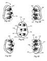
- FIG. 11A is a superior-posterior-medial view of yet another glenoid component
- FIG. 11B is a superior-anterior-medial view of the glenoid component of FIG. 11A
- FIG. 11C is a medial view of the glenoid component of FIG. 11A
- FIG. 11D is an inferior-posterior-medial view of the glenoid component of FIG. 11A
- FIG. 11E is an inferior-anterior-medial view of the glenoid component of FIG. 11A ;
- FIG. 19H is an inferior view of the glenoid component of FIG. 19A ;
- FIG. 19I is a superior view of the glenoid component of FIG. 19A ;
- FIG. 19J is a medial view of the glenoid component of FIG. 19A ;
- FIG. 19K is a cross sectional view of the glenoid component of FIG. 19J , taken along section line 19 K- 19 K of FIG. 19J ;
- FIG. 19L is a cross sectional view of the glenoid component of FIG. 19J , taken along section line 19 L- 19 L of FIG. 19J ;
- FIG. 22I is a detail view of a working portion of the drill guide of FIG. 22A , as indicated by detail circle 22 I of FIG. 22E ;
- FIG. 22J is a detail view of a working portion of the drill guide of FIG. 22A , as indicated by detail circle 22 J of FIG. 22H ;
- FIG. 27A is an isometric view of a punch
- FIG. 27B is another isometric view of the punch of FIG. 27A from a different direction
- FIG. 27C is a side view of the punch of FIG. 27A ;
- FIG. 30 is an isometric view of the shoulder joint of FIG. 29 with the size template of FIG. 20A ;
- FIG. 32 is an isometric view of the scapula of FIG. 29 with the reamer of FIG. 21A ;
- FIG. 36 is an isometric view of the shoulder joint of FIG. 29 with the drill guide and drills of FIG. 25A ;
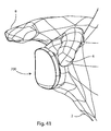
- FIG. 41 is an isometric view of the scapula of FIG. 29 and the glenoid component of FIG. 19A .
- the glenoid component 100 includes at least one anchoring element 138 which protrudes outwardly from the medial bone-facing surface 106 .
- the example shown includes a superior anchoring element 138 , an inferior anchoring element 140 , and a middle anchoring element 142 , although any number of anchoring elements may be present.
- the middle anchoring element 142 is positioned slightly anterior to the other anchoring elements 138 , 140 in order to more closely match the normal anatomy of the glenoid vault.
- Each anchoring element may be independently positioned on the medial bone-facing surface 106 , and may be independently sized.
- a glenoid component 200 includes a body 202 with a lateral articular surface 204 and an opposite medial bone-facing surface 206 .
- Glenoid component 200 includes the following features, which may be substantially similar to, or the same as, the corresponding features of glenoid component 100 : peripheral wall 208 , lateral peripheral edge 210 , lateral peripheral relief 212 , medial peripheral edge 214 , medial peripheral relief 216 , superior portion 218 , inferior portion 220 , anterior portion 222 , posterior portion 224 , S-I radius of curvature 226 , A-P radius of curvature 228 , inferior chamfer 230 , anterior relief 234 , posterior relief 236 , superior anchoring element 238 , inferior anchoring element 240 , middle anchoring element 242 , dowel or mast 248 , mast angle 250 , triangular reinforcement plate or sail 252 , supplementary angle 254 , pedestal 256 , face 257
- a glenoid component 500 includes a body 502 with a lateral articular surface 504 and an opposite medial bone-facing surface 506 .
- Glenoid component 500 includes the following features, which may be substantially similar to, or the same as, the corresponding features of glenoid component 100 : peripheral wall 508 , lateral peripheral edge 510 , medial peripheral edge 514 , superior portion 518 , inferior portion 520 , anterior portion 522 , posterior portion 524 , S-I radius of curvature 526 , A-P radius of curvature 528 , superior anchoring element 538 , inferior anchoring element 540 , dowel or mast 548 , mast angle 550 , triangular reinforcement plate or sail 552 , supplementary angle 554 .
- Glenoid component 500 lacks a lateral peripheral relief, medial peripheral relief, inferior chamfer, anterior relief, posterior relief, middle anchoring element, pedestal, face, fixation feature, ridge, groove, slot,
- FIGS. 20A-28C instruments for use with the disclosed glenoid prostheses will now be described.
- yet another drill guide 1700 includes a handle 1702 , a shaft 1704 , and a working portion 1706 .
- the shaft 1704 is bent, or zig-zag, in this example.
- Drill guide 1700 includes the following features, which may be substantially similar to, or the same as, the corresponding features of drill guide 1400 : body 1708 , first surface 1710 , bone-facing surface 1712 , hole 1714 , hole 1716 , hole 1718 , and protrusion 1720 .
- Drill guide 1700 also includes protrusion 1722 , protrusion 1724 , holes 1732 , 1734 , 1736 , and pegs 1744 , 1746 , 1748 .
- FIG. 38 illustrates the step of drilling a third set of plate holes.
- the drill guide 1800 is inserted between the humeral head and the glenoid fossa 4 so that the pegs 1844 , 1846 , 1848 are received in holes 16 , 18 , 22 , respectively.
- the drill 1890 is actuated through each one of holes 1814 , 1816 , 1818 to form plate holes 36 , 38 , 40 , respectively.
- FIG. 39 shows the scapula 2 after the third drilling step.
- the components disclosed herein may be fabricated from metals, alloys, polymers, plastics, ceramics, glasses, composite materials, or combinations thereof, including but not limited to: PEEK, titanium, titanium alloys, commercially pure titanium grade 2, ASTM F67, Nitinol, cobalt chrome, stainless steel, ultra high molecular weight polyethylene (UHMWPE), biocompatible materials, and biodegradable materials, among others. Different materials may be used for different parts. Coatings may be present. Different materials may be used within a single part. Any component disclosed herein may be colored, coded or otherwise marked to make it easier for a user to identify the type and size of the component, the setting, the function(s) of the component, and the like.
Abstract
Description
Claims (20)
Priority Applications (14)
| Application Number | Priority Date | Filing Date | Title |
|---|---|---|---|
| US29/468,456 USD730522S1 (en) | 2013-03-11 | 2013-09-30 | Implant |
| US14/042,258 US9775716B2 (en) | 2013-03-11 | 2013-09-30 | Glenoid arthroplasty |
| EP14716081.6A EP2967892B1 (en) | 2013-03-11 | 2014-03-07 | Glenoid arthroplasty |
| AU2014249514A AU2014249514B2 (en) | 2013-03-11 | 2014-03-07 | Glenoid arthroplasty |
| CA2941440A CA2941440A1 (en) | 2013-03-11 | 2014-03-07 | Glenoid arthroplasty |
| CN201480014210.4A CN105377195B (en) | 2013-03-11 | 2014-03-07 | Glenoid forms art |
| PCT/US2014/021567 WO2014164265A1 (en) | 2013-03-11 | 2014-03-07 | Glenoid arthroplasty |
| US14/592,837 US9814471B2 (en) | 2013-03-11 | 2015-01-08 | Glenoid arthroplasty and offset reamers |
| US29/524,099 USD759819S1 (en) | 2013-03-11 | 2015-04-16 | Glenoid implant |
| US29/568,298 USD810940S1 (en) | 2013-03-11 | 2016-06-16 | Implant |
| US15/587,895 US20170239058A1 (en) | 2013-03-11 | 2017-05-05 | Glenoid arthroplasty |
| US15/660,942 US10973646B2 (en) | 2013-03-11 | 2017-07-26 | Stabilized drill guide |
| US15/918,088 US11007063B2 (en) | 2013-03-11 | 2018-03-12 | Offset reamers |
| US17/322,226 US20210290404A1 (en) | 2013-03-11 | 2021-05-17 | Offset reamers |
Applications Claiming Priority (2)
| Application Number | Priority Date | Filing Date | Title |
|---|---|---|---|
| US201361776398P | 2013-03-11 | 2013-03-11 | |
| US14/042,258 US9775716B2 (en) | 2013-03-11 | 2013-09-30 | Glenoid arthroplasty |
Related Parent Applications (3)
| Application Number | Title | Priority Date | Filing Date |
|---|---|---|---|
| US14/042,258 Continuation-In-Part US9775716B2 (en) | 2013-03-11 | 2013-09-30 | Glenoid arthroplasty |
| US15/228,443 Continuation-In-Part US9814588B2 (en) | 2013-03-11 | 2016-08-04 | Glenoid arthroplasty with multi-directional fixation |
| US15/587,895 Continuation-In-Part US20170239058A1 (en) | 2013-03-11 | 2017-05-05 | Glenoid arthroplasty |
Related Child Applications (5)
| Application Number | Title | Priority Date | Filing Date |
|---|---|---|---|
| US14/042,258 Continuation-In-Part US9775716B2 (en) | 2013-03-11 | 2013-09-30 | Glenoid arthroplasty |
| US29/468,456 Continuation USD730522S1 (en) | 2013-03-11 | 2013-09-30 | Implant |
| US14/592,837 Continuation-In-Part US9814471B2 (en) | 2013-03-11 | 2015-01-08 | Glenoid arthroplasty and offset reamers |
| US15/587,895 Continuation US20170239058A1 (en) | 2013-03-11 | 2017-05-05 | Glenoid arthroplasty |
| US15/660,942 Continuation-In-Part US10973646B2 (en) | 2013-03-11 | 2017-07-26 | Stabilized drill guide |
Publications (2)
| Publication Number | Publication Date |
|---|---|
| US20140257495A1 US20140257495A1 (en) | 2014-09-11 |
| US9775716B2 true US9775716B2 (en) | 2017-10-03 |
Family
ID=51488806
Family Applications (5)
| Application Number | Title | Priority Date | Filing Date |
|---|---|---|---|
| US29/468,456 Active USD730522S1 (en) | 2013-03-11 | 2013-09-30 | Implant |
| US14/042,258 Active US9775716B2 (en) | 2013-03-11 | 2013-09-30 | Glenoid arthroplasty |
| US29/524,099 Active USD759819S1 (en) | 2013-03-11 | 2015-04-16 | Glenoid implant |
| US29/568,298 Active USD810940S1 (en) | 2013-03-11 | 2016-06-16 | Implant |
| US15/587,895 Abandoned US20170239058A1 (en) | 2013-03-11 | 2017-05-05 | Glenoid arthroplasty |
Family Applications Before (1)
| Application Number | Title | Priority Date | Filing Date |
|---|---|---|---|
| US29/468,456 Active USD730522S1 (en) | 2013-03-11 | 2013-09-30 | Implant |
Family Applications After (3)
| Application Number | Title | Priority Date | Filing Date |
|---|---|---|---|
| US29/524,099 Active USD759819S1 (en) | 2013-03-11 | 2015-04-16 | Glenoid implant |
| US29/568,298 Active USD810940S1 (en) | 2013-03-11 | 2016-06-16 | Implant |
| US15/587,895 Abandoned US20170239058A1 (en) | 2013-03-11 | 2017-05-05 | Glenoid arthroplasty |
Country Status (6)
| Country | Link |
|---|---|
| US (5) | USD730522S1 (en) |
| EP (1) | EP2967892B1 (en) |
| CN (1) | CN105377195B (en) |
| AU (1) | AU2014249514B2 (en) |
| CA (1) | CA2941440A1 (en) |
| WO (1) | WO2014164265A1 (en) |
Cited By (4)
| Publication number | Priority date | Publication date | Assignee | Title |
|---|---|---|---|---|
| US20170319348A1 (en) * | 2015-08-10 | 2017-11-09 | Catalyst Orthoscience Inc. | Arthroplasty prostheses with multi-axis fixation |
| US11007063B2 (en) | 2013-03-11 | 2021-05-18 | Catalyst Orthoscience Inc. | Offset reamers |
| US11752000B2 (en) | 2020-03-03 | 2023-09-12 | Howmedica Osteonics Corp. | Glenoid implant with additively manufactured fixation posts |
| US11801151B2 (en) | 2019-03-12 | 2023-10-31 | Howmedica Osteonics Corp. | Anatomic shell 2-in-1 window trial |
Families Citing this family (25)
| Publication number | Priority date | Publication date | Assignee | Title |
|---|---|---|---|---|
| USD730522S1 (en) | 2013-03-11 | 2015-05-26 | Catalyst Orthopaedics Llc | Implant |
| US9814471B2 (en) | 2013-03-11 | 2017-11-14 | Catalyst Orthoscience Inc. | Glenoid arthroplasty and offset reamers |
| US10973646B2 (en) | 2013-03-11 | 2021-04-13 | Catalyst Orthoscience Inc. | Stabilized drill guide |
| US9814588B2 (en) | 2015-08-10 | 2017-11-14 | Catalyst Orthoscience Inc. | Glenoid arthroplasty with multi-directional fixation |
| US9713533B2 (en) * | 2014-12-02 | 2017-07-25 | Biomet Manufacturing, Llc | In-line pegged hybrid glenoid |
| CA3005230C (en) * | 2015-01-12 | 2021-11-09 | Wright Medical Technology, Inc. | Targeted screw for talar dome fixation |
| US9955984B2 (en) * | 2015-01-12 | 2018-05-01 | Biomet Manufacturing, Llc | Augmented glenoid and method for preparation |
| WO2016114880A1 (en) * | 2015-01-16 | 2016-07-21 | Zimmer, Inc. | Glenoid implant pegs with backfill features |
| GB201505212D0 (en) | 2015-03-26 | 2015-05-13 | Imp Innovations Ltd | Prosthetic glenoid component |
| USD835276S1 (en) * | 2015-09-11 | 2018-12-04 | United Orthopedic Corporation | Keeled glenoid |
| USD775353S1 (en) * | 2015-10-29 | 2016-12-27 | Gregg C. Anderson | Vertebral distraction device |
| US10182917B2 (en) * | 2016-04-11 | 2019-01-22 | Arthrex, Inc. | Components for artificial joints |
| AU2017298302B2 (en) * | 2016-07-18 | 2022-07-28 | Catalyst Orthoscience Inc. | Arthroplasty prostheses with multi-axis fixation |
| HUE054262T2 (en) * | 2017-01-19 | 2021-08-30 | Encore Medical L P D/B/A Djo Surgical | Shoulder implant components |
| IT201700041420A1 (en) * | 2017-04-13 | 2018-10-13 | Limacorporate Spa | Scapular anchorage for the attachment of a glenoid component of a shoulder joint prosthesis to a scapula with impaired anatomy, and relative method of making said scapular anchorage |
| US11510785B2 (en) | 2017-04-25 | 2022-11-29 | Biomet Manufacturing, Llc | Augmented glenoid with groove |
| CN110650694B (en) * | 2017-05-23 | 2023-04-18 | 拜欧米特制造有限责任公司 | Offset guide |
| AT521922B1 (en) | 2018-11-23 | 2022-04-15 | Peter Schuller Goetzburg Dr | glenoid prosthesis |
| CN109771104A (en) * | 2019-03-11 | 2019-05-21 | 北京力达康科技有限公司 | A kind of MTS medial tibial plateau sticking patch, assembly type MTS medial tibial plateau sticking patch and its minimally invasive method of replacing |
| DK3914166T3 (en) * | 2019-05-14 | 2023-01-09 | Loci Orthopaedics Ltd | Værktøjssæt til installation af et implantat |
| AU2020204539A1 (en) * | 2019-07-12 | 2021-01-28 | Howmedica Osteonics Corp. | Augmented glenoid design |
| AU2020207869A1 (en) * | 2019-08-01 | 2021-02-18 | Howmedica Osteonics Corp. | Hybrid metal-backed glenoid component |
| EP3838231A1 (en) * | 2019-12-16 | 2021-06-23 | Waldemar Link GmbH & Co. KG | Component for a joint replacement |
| US20230038980A1 (en) * | 2020-03-25 | 2023-02-09 | Howmedica Osteonics Corp. | Metaphyseal referencing technique and instrument |
| WO2024059228A1 (en) | 2022-09-14 | 2024-03-21 | ARCA By OrthoAgile, LLC | Glenoid replacement system and methods of implanting said glenoid replacement |
Citations (103)
| Publication number | Priority date | Publication date | Assignee | Title |
|---|---|---|---|---|
| US4106130A (en) | 1976-02-20 | 1978-08-15 | National Research Development Corporation | Endoprosthetic bone joint devices |
| US4206517A (en) | 1977-12-01 | 1980-06-10 | Biomedical Engineering Corp. | Floating center prosthetic joint |
| US4550450A (en) | 1984-07-24 | 1985-11-05 | Kinnett James G | Total shoulder prosthesis system |
| US4865605A (en) | 1988-02-02 | 1989-09-12 | Dines David M | Modular shoulder prosthesis |
| US4964865A (en) * | 1988-02-03 | 1990-10-23 | Intermedics Orthopedics, Inc. | Glenoid prosthesis and method of use |
| US4986833A (en) | 1989-05-05 | 1991-01-22 | Worland Richard L | Glenoid component for an artificial shoulder joint |
| US5030219A (en) | 1990-01-22 | 1991-07-09 | Boehringer Mannheim Corporation | Glenoid component installation tools |
| US5032132A (en) | 1990-01-22 | 1991-07-16 | Boehringer Mannheim Corporation | Glenoid component |
| US5383936A (en) | 1992-09-26 | 1995-01-24 | Joachim Theusner | Artificial joint as an endoprosthesis for the human shoulder joint |
| US5489310A (en) | 1994-06-27 | 1996-02-06 | Mikhail; W. E. Michael | Universal glenoid shoulder prosthesis and method for implanting |
| GB2308068A (en) | 1995-12-11 | 1997-06-18 | Merck Biomaterial France | Total phalangeal joint prosthesis |
| US5702447A (en) * | 1995-11-30 | 1997-12-30 | Tornier S.A. | Device for the attachment of a glenoid prosthesis of the shoulder blade |
| US5723018A (en) | 1992-11-17 | 1998-03-03 | Cyprien; Jean-Maxwell | Shoulder-joint endoprosthesis |
| WO1998015241A1 (en) | 1996-10-09 | 1998-04-16 | Minnesota Mining And Manufacturing Company | Shoulder prosthesis |
| US5769856A (en) | 1996-06-24 | 1998-06-23 | Osteonics Corp. | Drill guide and implant method |
| US5800551A (en) | 1997-03-10 | 1998-09-01 | Biomet, Inc. | Apparatus and method for shoulder arthroplasty |
| US5814049A (en) | 1995-10-27 | 1998-09-29 | Kinamed, Inc. | Process for applying suction to bone drilling and reaming operations |
| US5919195A (en) | 1998-01-20 | 1999-07-06 | Johnson & Johnson Professional, Inc. | Oblong acetabular component instrumentation |
| US5928285A (en) | 1997-05-30 | 1999-07-27 | Bristol-Myers Squibb Co. | Orthopaedic implant having an articulating surface with a conforming and translational surface |
| US5976144A (en) | 1998-03-18 | 1999-11-02 | Vozeh Equipment Corp. | Hollow dome reamer with removable teeth |
| WO2000018335A1 (en) | 1998-09-25 | 2000-04-06 | Sulzer Orthopedics Inc. | Implantable humeral prosthesis having offset head and stem connection |
| US6129732A (en) | 1998-10-09 | 2000-10-10 | Precifar S.A. | Surgical reamer |
| US6245074B1 (en) | 1999-09-01 | 2001-06-12 | Bristol-Myers Squibb Co. | Orthopaedic glenoid reamer |
| EP1159939A1 (en) | 2000-05-30 | 2001-12-05 | Biomet Merck France | Total wrist prosthesis |
| WO2002017822A1 (en) | 2000-09-01 | 2002-03-07 | Wolf Eugene M | Facile total shoulder arthroplasty apparatus and method |
| US6364910B1 (en) * | 2001-07-11 | 2002-04-02 | Biomet, Inc. | Method and apparatus for use of a glenoid component |
| US6379386B1 (en) | 1997-09-09 | 2002-04-30 | Stryker Technologies Corporation | Anatomic glenoid shoulder prosthesis together with methods and tools for implanting same |
| US6406495B1 (en) | 1998-12-22 | 2002-06-18 | Sulzer Orthopedics Ltd. | Glenoid prosthesis and a modular system with glenoid prostheses |
| FR2825263A1 (en) | 2001-05-30 | 2002-12-06 | Tecknimed | Shoulder joint prosthesis has cap on humerus to engage socket with movement limiting stop surfaces |
| DE10130796A1 (en) | 2001-06-26 | 2003-01-23 | Ulrich Muender | Implantable replacement finger joint prosthesis system of modular structure, with proximal and distal implant elements, has a configuration and a mode of functioning making it adaptable for different applications |
| DE10134511A1 (en) | 2001-07-16 | 2003-02-20 | Ulrich Muender | Implantable condular big toe endoprosthesis system made up of a proximal implant and a distal implant has an anatomy-compatible geometry capable of being adapted to different particular requirements |
| US20030187449A1 (en) | 2002-03-29 | 2003-10-02 | Mccleary Larry G. | Medical instrument for milling a curved path in bone and procedure |
| US20030204263A1 (en) | 2002-04-25 | 2003-10-30 | Justin Daniel F. | Modular bone implant, tool, and method |
| US6679916B1 (en) * | 2002-04-29 | 2004-01-20 | Mark A. Frankle | Shoulder prosthesis system |
| US6783549B1 (en) | 2001-07-27 | 2004-08-31 | Biomet, Inc. | Modular humeral head resurfacing system |
| US20050049709A1 (en) * | 2003-08-25 | 2005-03-03 | Alain Tornier | Glenoid component of a shoulder prosthesis and complete shoulder prosthesis incorporating such a component |
| EP1518519A2 (en) | 2003-09-24 | 2005-03-30 | Biomet Manufacturing Corp. | Extended articular surface resurfacing head |
| US6875234B2 (en) | 2001-02-21 | 2005-04-05 | The New York, Society For The Ruptured And Crippled Maintaining Hospital For Special Surgery | Dual-radius glenoid prosthetic component for total shoulder arthroplasty |
| US6911047B2 (en) | 2000-03-17 | 2005-06-28 | Depuy Orthopaedics, Inc. | Apparatus and method for securing a cementless glenoid component to a glenoid surface of a scapula |
| US20050222572A1 (en) | 2002-02-08 | 2005-10-06 | Gursharan Chana | Surgical devices and methods of use |
| US7008430B2 (en) | 2003-01-31 | 2006-03-07 | Howmedica Osteonics Corp. | Adjustable reamer with tip tracker linkage |
| US20060074430A1 (en) | 2004-09-27 | 2006-04-06 | Deffenbaugh Daren L | Instrument for preparing an implant support surface and associated method |
| US20060094958A1 (en) | 2004-10-28 | 2006-05-04 | Marquart Joel G | Method and apparatus for calibrating non-linear instruments |
| US20060111787A1 (en) | 2004-11-05 | 2006-05-25 | Bailie David S | Glenoid prosthesis and method of implanting same |
| WO2006110896A2 (en) | 2005-04-12 | 2006-10-19 | The University Of Vermont And State Agriculture College | Knee prosthesis |
| US20070055380A1 (en) | 2005-09-08 | 2007-03-08 | Biomet Manufacturing Corp | Method and apparatus for a glenoid prosthesis |
| US7204854B2 (en) | 2002-08-15 | 2007-04-17 | Arthrex, Inc. | Metal back prosthetic glenoid component with cemented pegs and hollow metal cage screw |
| US7217272B2 (en) | 2003-11-25 | 2007-05-15 | Symmetry Medical, Inc. | Orthopaedic rotary reamer with implant compliant cutting teeth |
| US20070142917A1 (en) | 2005-10-26 | 2007-06-21 | Roche Christopher P | Apparatus and method to obtain bone fixation |
| US20070219637A1 (en) | 2006-03-20 | 2007-09-20 | Berelsman Brian K | Modular center pegged glenoid |
| US20070219638A1 (en) | 2005-10-24 | 2007-09-20 | Benoist Girard Sas | Prosthetic glenoid component |
| US20070225817A1 (en) | 2006-03-21 | 2007-09-27 | Reubelt Leo M | Glenoid component with improved fixation stability |
| US20070225818A1 (en) | 2006-03-21 | 2007-09-27 | Axiom Orthopaedics, Inc. | Non-spherical articulating surfaces in shoulder and hip replacement |
| WO2007109800A2 (en) | 2006-03-23 | 2007-09-27 | Exactech, Inc. | Reverse shoulder prosthesis |
| US7294149B2 (en) | 2003-12-05 | 2007-11-13 | Howmedica Osteonics Corp. | Orthopedic implant with angled pegs |
| US20070299529A1 (en) | 2006-06-22 | 2007-12-27 | Depuy Products, Inc. | Tibial insert having multiple keels |
| US7329284B2 (en) | 2002-09-27 | 2008-02-12 | Depuy Products, Inc. | Concave resurfacing prosthesis |
| US20080147070A1 (en) | 2006-12-13 | 2008-06-19 | Hassler Michel | Reamer for surgical use |
| US20090125113A1 (en) | 2007-11-07 | 2009-05-14 | Guederian Gregory A | Hybrid glenoid for shoulder arthroplasty |
| US20090192621A1 (en) | 2003-10-08 | 2009-07-30 | Biomet Manufacturing Corp. | Shoulder Implant Assembly |
| WO2009108591A1 (en) | 2008-02-28 | 2009-09-03 | Schwartz Biomedical, Llc | Partial joint resurfacing implant, instrumentation, and method |
| US20090226068A1 (en) | 2008-03-05 | 2009-09-10 | Conformis, Inc. | Implants for Altering Wear Patterns of Articular Surfaces |
| US7588572B2 (en) | 1999-03-18 | 2009-09-15 | Greatbatch Medical S.A. | Connector for domed cutting tool |
| US7621962B2 (en) | 2002-02-06 | 2009-11-24 | Biomet Manufacturing Corp. | Modular resurfacing prosthetic |
| US20100087877A1 (en) | 2005-02-25 | 2010-04-08 | Shoulder Innovations, Llc | Methods of implanting glenoid inlay |
| US20100161065A1 (en) | 2008-12-23 | 2010-06-24 | Depuy Products, Inc. | Shoulder Prosthesis with Vault-Filling Structure having Bone-Sparing Configuration |
| US7780669B2 (en) | 2002-04-30 | 2010-08-24 | Greatbatch Medical S.A. | Reamer spindle for minimally invasive joint surgery |
| US20100241235A1 (en) | 2009-03-20 | 2010-09-23 | Depuy Products, Inc. | Glenoid Component for Use in Shoulder Arthroplasty and Associated Method of Implanting Same |
| EP2238949A1 (en) | 2009-03-05 | 2010-10-13 | Tornier, Inc. | Glenoid implant anchor post |
| US7815685B2 (en) | 2000-12-01 | 2010-10-19 | Depuy International Ltd. | Orthopaedic joint prosthesis |
| US20100268239A1 (en) | 2009-04-17 | 2010-10-21 | Arthrosurface Incorporated | Glenoid Resurfacing System and Method |
| US7867234B2 (en) | 2003-10-06 | 2011-01-11 | Howmedica Osteonics Corp. | Reamer bushing |
| US20110035013A1 (en) | 2006-03-20 | 2011-02-10 | Biomet Manufacturing Corp. | Modular center pegged glenoid |
| US20110106266A1 (en) | 2008-04-28 | 2011-05-05 | Smith & Nephew Orthopaedics Ag | Scapular component of a shoulder joint prosthesis |
| US20110230972A1 (en) | 2009-09-18 | 2011-09-22 | Biomet Manufacturing Corp. | Elbow resurfacing prosthesis |
| US8080063B2 (en) * | 2006-04-13 | 2011-12-20 | Tornier Sas | Glenoid component with an anatomically optimized keel |
| WO2012030794A1 (en) | 2010-09-01 | 2012-03-08 | Mayo Foundation For Medical Education And Research | Method for optimization of joint arthroplasty component design |
| US8157866B2 (en) | 2007-11-05 | 2012-04-17 | Biomet Manufacturing Corp. | Method and apparatus for performing a less invasive shoulder procedure |
| EP2446859A1 (en) | 2010-10-28 | 2012-05-02 | Les Laboratoires Osteal Medical | Glenoid implant. |
| US20120130498A1 (en) | 2010-11-24 | 2012-05-24 | Depuy Products, Inc. | Modular glenoid prosthesis |
| US20120130500A1 (en) | 2001-01-23 | 2012-05-24 | Depuy Products, Inc. | Procedure for the Treatment of Cuff Tear Arthropathy |
| US20120209392A1 (en) | 2011-02-07 | 2012-08-16 | Exactech, Inc. | Adjustable reverse shoulder prostheses |
| US8308809B2 (en) | 2007-12-08 | 2012-11-13 | Depuy International Limited | Method of implanting an implant including bone abrasion |
| US20130024000A1 (en) | 2001-05-25 | 2013-01-24 | Conformis, Inc. | Patient Selectable Joint Arthroplasty Devices and Surgical Tools |
| WO2013020026A1 (en) | 2011-08-03 | 2013-02-07 | Conformis, Inc. | Automated design, selection, manufacturing and implantation of patient-adapted and improved articular implants, designs and related guide tools |
| US8444646B2 (en) | 2003-03-31 | 2013-05-21 | Depuy Products, Inc. | Bone preparation tool kit and associated method |
| US20130144393A1 (en) | 2009-12-14 | 2013-06-06 | Austin W. Mutchler | Shoulder prosthesis glenoid component |
| US8475460B1 (en) | 2010-02-23 | 2013-07-02 | Greatbatch Medical S.A. | Angled reamer spindle for minimally invasive hip replacement surgery |
| US8591592B2 (en) | 2007-05-01 | 2013-11-26 | Arthrex, Inc. | Method of implanting partial humeral head prosthesis |
| WO2014005644A1 (en) | 2012-07-05 | 2014-01-09 | Limacorporate S.P.A. | Humeral implant for a shoulder prosthesis |
| CA2821529A1 (en) | 2012-07-26 | 2014-01-26 | Howmedica Osteonics Corp. | Cement pressurizing glenoid |
| US8764836B2 (en) | 2011-03-18 | 2014-07-01 | Lieven de Wilde | Circular glenoid method for shoulder arthroplasty |
| US8778028B2 (en) | 2005-02-25 | 2014-07-15 | Shoulder Innovations, Inc. | Methods and devices for less invasive glenoid replacement |
| WO2014164265A1 (en) | 2013-03-11 | 2014-10-09 | Coorstek Medical Llc D/B/A Imds | Glenoid arthroplasty |
| US8974537B2 (en) | 2007-05-01 | 2015-03-10 | Arthrex, Inc. | Method for an articulating humeral head prosthesis |
| US20150119891A1 (en) | 2013-03-11 | 2015-04-30 | Catalyst Orthopaedics Llc | Glenoid arthroplasty and offset reamers |
| US9119643B2 (en) | 2005-03-31 | 2015-09-01 | Biomet Manufacturing, Llc | Method and apparatus for performing a less invasive shoulder procedure |
| US20150320567A1 (en) | 2014-05-12 | 2015-11-12 | Integra Lifesciences Corporation | Total Ankle Replacement Prosthesis |
| US9237894B2 (en) | 2013-01-31 | 2016-01-19 | Depuy Mitek, Llc | Methods and devices for forming holes in bone to stimulate bone growth |
| US9283076B2 (en) | 2009-04-17 | 2016-03-15 | Arthrosurface Incorporated | Glenoid resurfacing system and method |
| US9351844B2 (en) | 2010-10-22 | 2016-05-31 | Tornier, Inc. | Set of glenoid components for a shoulder prosthesis |
| US20160287266A1 (en) | 2009-04-17 | 2016-10-06 | Arthrosurface Incorporated | Glenoid repair system and methods of use thereof |
| US20170042689A1 (en) | 2015-08-10 | 2017-02-16 | Catalyst Orthopaedics Llc | Glenoid arthroplasty with multi-directional fixation |
Family Cites Families (11)
| Publication number | Priority date | Publication date | Assignee | Title |
|---|---|---|---|---|
| US5489309A (en) | 1993-01-06 | 1996-02-06 | Smith & Nephew Richards Inc. | Modular humeral component system |
| FR2836821B1 (en) | 2002-03-11 | 2004-05-28 | Biomet Merck France | UNICOMPARTMENTAL PROSTHESIS FOR KNEE |
| US8165148B2 (en) * | 2003-01-13 | 2012-04-24 | Qualcomm Incorporated | System and method for rate assignment |
| ATE503442T1 (en) * | 2004-05-19 | 2011-04-15 | Zimmer Gmbh | GLENOID ANCHORAGE |
| GB0503529D0 (en) | 2005-02-21 | 2005-03-30 | Smith & Nephew Inc | Medical device |
| US20090005798A1 (en) | 2005-06-01 | 2009-01-01 | Bruso Sarl | Tool-Holder Instrument |
| ES2335121T3 (en) | 2006-05-12 | 2010-03-22 | Synthes Gmbh | ARTICULAR ENDOPROTESIS. |
| US8882845B2 (en) | 2010-05-05 | 2014-11-11 | DePuy Synthes Products, LLC | Mobile bearing glenoid prosthesis |
| WO2011150180A2 (en) | 2010-05-26 | 2011-12-01 | Orbis Medical Group Llc | Implantable prostheses |
| US8551177B2 (en) | 2011-03-18 | 2013-10-08 | DePuy Synthes Products, LLC | Revision glenoid kit |
| US8795279B2 (en) | 2012-05-16 | 2014-08-05 | Biomet Manufacturing, Llc | Peripheral peg drill component |
-
2013
- 2013-09-30 US US29/468,456 patent/USD730522S1/en active Active
- 2013-09-30 US US14/042,258 patent/US9775716B2/en active Active
-
2014
- 2014-03-07 CN CN201480014210.4A patent/CN105377195B/en active Active
- 2014-03-07 EP EP14716081.6A patent/EP2967892B1/en active Active
- 2014-03-07 CA CA2941440A patent/CA2941440A1/en not_active Abandoned
- 2014-03-07 WO PCT/US2014/021567 patent/WO2014164265A1/en active Application Filing
- 2014-03-07 AU AU2014249514A patent/AU2014249514B2/en active Active
-
2015
- 2015-04-16 US US29/524,099 patent/USD759819S1/en active Active
-
2016
- 2016-06-16 US US29/568,298 patent/USD810940S1/en active Active
-
2017
- 2017-05-05 US US15/587,895 patent/US20170239058A1/en not_active Abandoned
Patent Citations (144)
| Publication number | Priority date | Publication date | Assignee | Title |
|---|---|---|---|---|
| US4106130A (en) | 1976-02-20 | 1978-08-15 | National Research Development Corporation | Endoprosthetic bone joint devices |
| US4206517A (en) | 1977-12-01 | 1980-06-10 | Biomedical Engineering Corp. | Floating center prosthetic joint |
| US4550450A (en) | 1984-07-24 | 1985-11-05 | Kinnett James G | Total shoulder prosthesis system |
| US4865605A (en) | 1988-02-02 | 1989-09-12 | Dines David M | Modular shoulder prosthesis |
| US4964865A (en) * | 1988-02-03 | 1990-10-23 | Intermedics Orthopedics, Inc. | Glenoid prosthesis and method of use |
| US4986833A (en) | 1989-05-05 | 1991-01-22 | Worland Richard L | Glenoid component for an artificial shoulder joint |
| US5030219A (en) | 1990-01-22 | 1991-07-09 | Boehringer Mannheim Corporation | Glenoid component installation tools |
| US5032132A (en) | 1990-01-22 | 1991-07-16 | Boehringer Mannheim Corporation | Glenoid component |
| US5383936A (en) | 1992-09-26 | 1995-01-24 | Joachim Theusner | Artificial joint as an endoprosthesis for the human shoulder joint |
| US5723018A (en) | 1992-11-17 | 1998-03-03 | Cyprien; Jean-Maxwell | Shoulder-joint endoprosthesis |
| US5489310A (en) | 1994-06-27 | 1996-02-06 | Mikhail; W. E. Michael | Universal glenoid shoulder prosthesis and method for implanting |
| US5814049A (en) | 1995-10-27 | 1998-09-29 | Kinamed, Inc. | Process for applying suction to bone drilling and reaming operations |
| US5702447A (en) * | 1995-11-30 | 1997-12-30 | Tornier S.A. | Device for the attachment of a glenoid prosthesis of the shoulder blade |
| GB2308068A (en) | 1995-12-11 | 1997-06-18 | Merck Biomaterial France | Total phalangeal joint prosthesis |
| US5769856A (en) | 1996-06-24 | 1998-06-23 | Osteonics Corp. | Drill guide and implant method |
| WO1998015241A1 (en) | 1996-10-09 | 1998-04-16 | Minnesota Mining And Manufacturing Company | Shoulder prosthesis |
| US5944758A (en) | 1996-10-09 | 1999-08-31 | Minnesota Mining And Manufacturing Company | Shoulder prosthesis |
| US5800551A (en) | 1997-03-10 | 1998-09-01 | Biomet, Inc. | Apparatus and method for shoulder arthroplasty |
| US5928285A (en) | 1997-05-30 | 1999-07-27 | Bristol-Myers Squibb Co. | Orthopaedic implant having an articulating surface with a conforming and translational surface |
| US6379386B1 (en) | 1997-09-09 | 2002-04-30 | Stryker Technologies Corporation | Anatomic glenoid shoulder prosthesis together with methods and tools for implanting same |
| US6673115B2 (en) | 1997-09-09 | 2004-01-06 | Stryker Technologies Corporation | Anatomic glenoid shoulder prosthesis together with methods and tools for implanting same |
| US20020082702A1 (en) | 1997-09-09 | 2002-06-27 | Herbert Resch | Anatomic glenoid shoulder prosthesis together with methods and tools for implanting same |
| US5919195A (en) | 1998-01-20 | 1999-07-06 | Johnson & Johnson Professional, Inc. | Oblong acetabular component instrumentation |
| US5976144A (en) | 1998-03-18 | 1999-11-02 | Vozeh Equipment Corp. | Hollow dome reamer with removable teeth |
| US7048740B2 (en) | 1998-03-18 | 2006-05-23 | Precimed Sa | Connector for domed cutting tool |
| US6475221B1 (en) | 1998-03-18 | 2002-11-05 | Patrick M. White | Connector for domed cutting tool |
| WO2000018335A1 (en) | 1998-09-25 | 2000-04-06 | Sulzer Orthopedics Inc. | Implantable humeral prosthesis having offset head and stem connection |
| US6129732A (en) | 1998-10-09 | 2000-10-10 | Precifar S.A. | Surgical reamer |
| US6406495B1 (en) | 1998-12-22 | 2002-06-18 | Sulzer Orthopedics Ltd. | Glenoid prosthesis and a modular system with glenoid prostheses |
| US7588572B2 (en) | 1999-03-18 | 2009-09-15 | Greatbatch Medical S.A. | Connector for domed cutting tool |
| US6245074B1 (en) | 1999-09-01 | 2001-06-12 | Bristol-Myers Squibb Co. | Orthopaedic glenoid reamer |
| US7160328B2 (en) | 2000-03-17 | 2007-01-09 | Deputy Products, Inc. | Method for securing a glenoid component to a scapula |
| US6911047B2 (en) | 2000-03-17 | 2005-06-28 | Depuy Orthopaedics, Inc. | Apparatus and method for securing a cementless glenoid component to a glenoid surface of a scapula |
| EP1159939A1 (en) | 2000-05-30 | 2001-12-05 | Biomet Merck France | Total wrist prosthesis |
| WO2002017822A1 (en) | 2000-09-01 | 2002-03-07 | Wolf Eugene M | Facile total shoulder arthroplasty apparatus and method |
| US7815685B2 (en) | 2000-12-01 | 2010-10-19 | Depuy International Ltd. | Orthopaedic joint prosthesis |
| US20120130500A1 (en) | 2001-01-23 | 2012-05-24 | Depuy Products, Inc. | Procedure for the Treatment of Cuff Tear Arthropathy |
| US6875234B2 (en) | 2001-02-21 | 2005-04-05 | The New York, Society For The Ruptured And Crippled Maintaining Hospital For Special Surgery | Dual-radius glenoid prosthetic component for total shoulder arthroplasty |
| US20130024000A1 (en) | 2001-05-25 | 2013-01-24 | Conformis, Inc. | Patient Selectable Joint Arthroplasty Devices and Surgical Tools |
| FR2825263A1 (en) | 2001-05-30 | 2002-12-06 | Tecknimed | Shoulder joint prosthesis has cap on humerus to engage socket with movement limiting stop surfaces |
| DE10130796A1 (en) | 2001-06-26 | 2003-01-23 | Ulrich Muender | Implantable replacement finger joint prosthesis system of modular structure, with proximal and distal implant elements, has a configuration and a mode of functioning making it adaptable for different applications |
| US6364910B1 (en) * | 2001-07-11 | 2002-04-02 | Biomet, Inc. | Method and apparatus for use of a glenoid component |
| DE10134511A1 (en) | 2001-07-16 | 2003-02-20 | Ulrich Muender | Implantable condular big toe endoprosthesis system made up of a proximal implant and a distal implant has an anatomy-compatible geometry capable of being adapted to different particular requirements |
| US6783549B1 (en) | 2001-07-27 | 2004-08-31 | Biomet, Inc. | Modular humeral head resurfacing system |
| US7621962B2 (en) | 2002-02-06 | 2009-11-24 | Biomet Manufacturing Corp. | Modular resurfacing prosthetic |
| US20050222572A1 (en) | 2002-02-08 | 2005-10-06 | Gursharan Chana | Surgical devices and methods of use |
| US20030187449A1 (en) | 2002-03-29 | 2003-10-02 | Mccleary Larry G. | Medical instrument for milling a curved path in bone and procedure |
| US20030204263A1 (en) | 2002-04-25 | 2003-10-30 | Justin Daniel F. | Modular bone implant, tool, and method |
| US6679916B1 (en) * | 2002-04-29 | 2004-01-20 | Mark A. Frankle | Shoulder prosthesis system |
| US7780669B2 (en) | 2002-04-30 | 2010-08-24 | Greatbatch Medical S.A. | Reamer spindle for minimally invasive joint surgery |
| US7204854B2 (en) | 2002-08-15 | 2007-04-17 | Arthrex, Inc. | Metal back prosthetic glenoid component with cemented pegs and hollow metal cage screw |
| US7329284B2 (en) | 2002-09-27 | 2008-02-12 | Depuy Products, Inc. | Concave resurfacing prosthesis |
| US9180016B2 (en) | 2002-09-27 | 2015-11-10 | DePuy Synthes Products, Inc. | Concave resurfacing prosthesis kit |
| US8673015B2 (en) | 2002-09-27 | 2014-03-18 | DePuy Synthes Products, LLC | Concave resurfacing prosthesis |
| US20080109000A1 (en) | 2002-09-27 | 2008-05-08 | Depuy Products, Inc. | Tamp for concave resurfacing prosthesis |
| US7008430B2 (en) | 2003-01-31 | 2006-03-07 | Howmedica Osteonics Corp. | Adjustable reamer with tip tracker linkage |
| US8444646B2 (en) | 2003-03-31 | 2013-05-21 | Depuy Products, Inc. | Bone preparation tool kit and associated method |
| US20050049709A1 (en) * | 2003-08-25 | 2005-03-03 | Alain Tornier | Glenoid component of a shoulder prosthesis and complete shoulder prosthesis incorporating such a component |
| US20120310360A1 (en) | 2003-09-24 | 2012-12-06 | Biomet Manufacturing Corp. | Extended articular surface resurfacing head |
| EP1518519A2 (en) | 2003-09-24 | 2005-03-30 | Biomet Manufacturing Corp. | Extended articular surface resurfacing head |
| US7670382B2 (en) | 2003-09-24 | 2010-03-02 | Biomet Manufacturing Corp. | Extended articular surface resurfacing head |
| US7867234B2 (en) | 2003-10-06 | 2011-01-11 | Howmedica Osteonics Corp. | Reamer bushing |
| US20090192621A1 (en) | 2003-10-08 | 2009-07-30 | Biomet Manufacturing Corp. | Shoulder Implant Assembly |
| US7217272B2 (en) | 2003-11-25 | 2007-05-15 | Symmetry Medical, Inc. | Orthopaedic rotary reamer with implant compliant cutting teeth |
| US7294149B2 (en) | 2003-12-05 | 2007-11-13 | Howmedica Osteonics Corp. | Orthopedic implant with angled pegs |
| US20060074430A1 (en) | 2004-09-27 | 2006-04-06 | Deffenbaugh Daren L | Instrument for preparing an implant support surface and associated method |
| US20060094958A1 (en) | 2004-10-28 | 2006-05-04 | Marquart Joel G | Method and apparatus for calibrating non-linear instruments |
| US20060111787A1 (en) | 2004-11-05 | 2006-05-25 | Bailie David S | Glenoid prosthesis and method of implanting same |
| US20100087877A1 (en) | 2005-02-25 | 2010-04-08 | Shoulder Innovations, Llc | Methods of implanting glenoid inlay |
| US20130166033A1 (en) | 2005-02-25 | 2013-06-27 | Shoulder Innovations, Llc | Methods for less invasive glenoid replacement |
| US9610166B2 (en) | 2005-02-25 | 2017-04-04 | Shoulder Innovations, Llc | Methods and devices for less invasive glenoid replacement |
| US8038719B2 (en) | 2005-02-25 | 2011-10-18 | Shoulder Innovations, Llc | Methods for less invasive glenoid replacement |
| US20100087876A1 (en) | 2005-02-25 | 2010-04-08 | Shoulder Innovations, Llc | Methods for less invasive glenoid replacement |
| US8778028B2 (en) | 2005-02-25 | 2014-07-15 | Shoulder Innovations, Inc. | Methods and devices for less invasive glenoid replacement |
| US8007538B2 (en) | 2005-02-25 | 2011-08-30 | Shoulder Innovations, Llc | Shoulder implant for glenoid replacement |
| US20160089164A1 (en) | 2005-03-31 | 2016-03-31 | Biomet Manufacturing, Llc. | Method and apparatus for performing a less invasive shoulder procedure |
| US9119643B2 (en) | 2005-03-31 | 2015-09-01 | Biomet Manufacturing, Llc | Method and apparatus for performing a less invasive shoulder procedure |
| WO2006110896A2 (en) | 2005-04-12 | 2006-10-19 | The University Of Vermont And State Agriculture College | Knee prosthesis |
| US20070055380A1 (en) | 2005-09-08 | 2007-03-08 | Biomet Manufacturing Corp | Method and apparatus for a glenoid prosthesis |
| US20070219638A1 (en) | 2005-10-24 | 2007-09-20 | Benoist Girard Sas | Prosthetic glenoid component |
| US20070142917A1 (en) | 2005-10-26 | 2007-06-21 | Roche Christopher P | Apparatus and method to obtain bone fixation |
| US20110035013A1 (en) | 2006-03-20 | 2011-02-10 | Biomet Manufacturing Corp. | Modular center pegged glenoid |
| US20070219637A1 (en) | 2006-03-20 | 2007-09-20 | Berelsman Brian K | Modular center pegged glenoid |
| US8425614B2 (en) | 2006-03-20 | 2013-04-23 | Biomet Manufacturing Corp. | Modular center pegged glenoid |
| US20070225818A1 (en) | 2006-03-21 | 2007-09-27 | Axiom Orthopaedics, Inc. | Non-spherical articulating surfaces in shoulder and hip replacement |
| US9433507B2 (en) | 2006-03-21 | 2016-09-06 | Tornier, Inc. | Non-spherical articulating surfaces in shoulder and hip replacement |
| US20170014238A1 (en) | 2006-03-21 | 2017-01-19 | Tornier, Inc. | Glenoid component with improved fixation stability |
| US20070225817A1 (en) | 2006-03-21 | 2007-09-27 | Reubelt Leo M | Glenoid component with improved fixation stability |
| US9474619B2 (en) | 2006-03-21 | 2016-10-25 | Tornier, Inc. | Glenoid component with improved fixation stability |
| WO2007109800A2 (en) | 2006-03-23 | 2007-09-27 | Exactech, Inc. | Reverse shoulder prosthesis |
| CN101442961B (en) | 2006-03-23 | 2012-11-07 | 精密技术公司 | Reverse shoulder prosthesis |
| US8870962B2 (en) | 2006-03-23 | 2014-10-28 | Exactech, Inc. | Reverse shoulder prosthesis |
| US9233003B2 (en) | 2006-03-23 | 2016-01-12 | Exactech Inc. | Reverse shoulder prosthesis |
| US8080063B2 (en) * | 2006-04-13 | 2011-12-20 | Tornier Sas | Glenoid component with an anatomically optimized keel |
| US20070299529A1 (en) | 2006-06-22 | 2007-12-27 | Depuy Products, Inc. | Tibial insert having multiple keels |
| US8540778B2 (en) * | 2006-06-22 | 2013-09-24 | DePuy Synthes Products, LLC | Tibial insert having multiple keels |
| US20080147070A1 (en) | 2006-12-13 | 2008-06-19 | Hassler Michel | Reamer for surgical use |
| US8974537B2 (en) | 2007-05-01 | 2015-03-10 | Arthrex, Inc. | Method for an articulating humeral head prosthesis |
| US8591592B2 (en) | 2007-05-01 | 2013-11-26 | Arthrex, Inc. | Method of implanting partial humeral head prosthesis |
| US8157866B2 (en) | 2007-11-05 | 2012-04-17 | Biomet Manufacturing Corp. | Method and apparatus for performing a less invasive shoulder procedure |
| US9370428B2 (en) | 2007-11-05 | 2016-06-21 | Biomet Manufacturing, Llc | Method and apparatus for performing a less invasive shoulder procedure |
| US20090125113A1 (en) | 2007-11-07 | 2009-05-14 | Guederian Gregory A | Hybrid glenoid for shoulder arthroplasty |
| US8048161B2 (en) | 2007-11-07 | 2011-11-01 | Arthex, Inc. | Hybrid glenoid for shoulder arthroplasty |
| US8308809B2 (en) | 2007-12-08 | 2012-11-13 | Depuy International Limited | Method of implanting an implant including bone abrasion |
| CN102014800B (en) | 2008-02-28 | 2014-04-30 | 比奥波利公司 | Partial joint resurfacing implant, instrumentation, and method |
| WO2009108591A1 (en) | 2008-02-28 | 2009-09-03 | Schwartz Biomedical, Llc | Partial joint resurfacing implant, instrumentation, and method |
| US20090226068A1 (en) | 2008-03-05 | 2009-09-10 | Conformis, Inc. | Implants for Altering Wear Patterns of Articular Surfaces |
| US20110106266A1 (en) | 2008-04-28 | 2011-05-05 | Smith & Nephew Orthopaedics Ag | Scapular component of a shoulder joint prosthesis |
| US20100161065A1 (en) | 2008-12-23 | 2010-06-24 | Depuy Products, Inc. | Shoulder Prosthesis with Vault-Filling Structure having Bone-Sparing Configuration |
| EP2238949A1 (en) | 2009-03-05 | 2010-10-13 | Tornier, Inc. | Glenoid implant anchor post |
| EP2559406A1 (en) | 2009-03-20 | 2013-02-20 | DePuy Products, Inc. | Glenoid component for use in shoulder arthroplasty |
| US20100241235A1 (en) | 2009-03-20 | 2010-09-23 | Depuy Products, Inc. | Glenoid Component for Use in Shoulder Arthroplasty and Associated Method of Implanting Same |
| US9283076B2 (en) | 2009-04-17 | 2016-03-15 | Arthrosurface Incorporated | Glenoid resurfacing system and method |
| US20160287266A1 (en) | 2009-04-17 | 2016-10-06 | Arthrosurface Incorporated | Glenoid repair system and methods of use thereof |
| US20100268239A1 (en) | 2009-04-17 | 2010-10-21 | Arthrosurface Incorporated | Glenoid Resurfacing System and Method |
| US20110230972A1 (en) | 2009-09-18 | 2011-09-22 | Biomet Manufacturing Corp. | Elbow resurfacing prosthesis |
| US20130144393A1 (en) | 2009-12-14 | 2013-06-06 | Austin W. Mutchler | Shoulder prosthesis glenoid component |
| US8475460B1 (en) | 2010-02-23 | 2013-07-02 | Greatbatch Medical S.A. | Angled reamer spindle for minimally invasive hip replacement surgery |
| US8480674B1 (en) | 2010-02-23 | 2013-07-09 | Greatbatch Medical S.A. | Angled reamer spindle for minimally invasive hip replacement surgery |
| WO2012030794A1 (en) | 2010-09-01 | 2012-03-08 | Mayo Foundation For Medical Education And Research | Method for optimization of joint arthroplasty component design |
| US20160242921A1 (en) | 2010-10-22 | 2016-08-25 | Tornier, Inc. | Set of glenoid components for a shoulder prosthesis |
| US9351844B2 (en) | 2010-10-22 | 2016-05-31 | Tornier, Inc. | Set of glenoid components for a shoulder prosthesis |
| EP2446859A1 (en) | 2010-10-28 | 2012-05-02 | Les Laboratoires Osteal Medical | Glenoid implant. |
| US20120130498A1 (en) | 2010-11-24 | 2012-05-24 | Depuy Products, Inc. | Modular glenoid prosthesis |
| US8465548B2 (en) | 2010-11-24 | 2013-06-18 | DePuy Synthes Products, LLC | Modular glenoid prosthesis |
| US20120209392A1 (en) | 2011-02-07 | 2012-08-16 | Exactech, Inc. | Adjustable reverse shoulder prostheses |
| US8764836B2 (en) | 2011-03-18 | 2014-07-01 | Lieven de Wilde | Circular glenoid method for shoulder arthroplasty |
| WO2013020026A1 (en) | 2011-08-03 | 2013-02-07 | Conformis, Inc. | Automated design, selection, manufacturing and implantation of patient-adapted and improved articular implants, designs and related guide tools |
| WO2014005644A1 (en) | 2012-07-05 | 2014-01-09 | Limacorporate S.P.A. | Humeral implant for a shoulder prosthesis |
| US20140031945A1 (en) | 2012-07-26 | 2014-01-30 | Howmedica Osteonics Corp. | Cement pressurizing glenoid |
| CA2821529A1 (en) | 2012-07-26 | 2014-01-26 | Howmedica Osteonics Corp. | Cement pressurizing glenoid |
| US8876907B2 (en) | 2012-07-26 | 2014-11-04 | Howmedica Osteonics Corp. | Cement pressurizing glenoid |
| EP2689751A1 (en) | 2012-07-26 | 2014-01-29 | Howmedica Osteonics Corp. | Cement pressurizing glenoid |
| US9237894B2 (en) | 2013-01-31 | 2016-01-19 | Depuy Mitek, Llc | Methods and devices for forming holes in bone to stimulate bone growth |
| US20160095607A1 (en) | 2013-01-31 | 2016-04-07 | Depuy Mitek, Llc | Methods and Devices for Forming Holes In Bone to Stimulate Bone Growth |
| US20150119891A1 (en) | 2013-03-11 | 2015-04-30 | Catalyst Orthopaedics Llc | Glenoid arthroplasty and offset reamers |
| EP2967892A1 (en) | 2013-03-11 | 2016-01-20 | Catalyst Orthopaedics LLC | Glenoid arthroplasty |
| USD759819S1 (en) | 2013-03-11 | 2016-06-21 | Catalyst Orthopaedics Llc | Glenoid implant |
| WO2014164265A1 (en) | 2013-03-11 | 2014-10-09 | Coorstek Medical Llc D/B/A Imds | Glenoid arthroplasty |
| CN105377195A (en) | 2013-03-11 | 2016-03-02 | 催化剂整形外科有限公司 | Glenoid arthroplasty |
| USD730522S1 (en) | 2013-03-11 | 2015-05-26 | Catalyst Orthopaedics Llc | Implant |
| WO2015106136A1 (en) | 2014-01-10 | 2015-07-16 | Catalyst Orthopaedics Llc | Glenoid arthroplasty and offset reamers |
| US20150320567A1 (en) | 2014-05-12 | 2015-11-12 | Integra Lifesciences Corporation | Total Ankle Replacement Prosthesis |
| US20170042689A1 (en) | 2015-08-10 | 2017-02-16 | Catalyst Orthopaedics Llc | Glenoid arthroplasty with multi-directional fixation |
Cited By (5)
| Publication number | Priority date | Publication date | Assignee | Title |
|---|---|---|---|---|
| US11007063B2 (en) | 2013-03-11 | 2021-05-18 | Catalyst Orthoscience Inc. | Offset reamers |
| US20170319348A1 (en) * | 2015-08-10 | 2017-11-09 | Catalyst Orthoscience Inc. | Arthroplasty prostheses with multi-axis fixation |
| US11007064B2 (en) | 2015-08-10 | 2021-05-18 | Catalyst Orthoscience Inc. | Arthroplasty prostheses with multi-axis fixation |
| US11801151B2 (en) | 2019-03-12 | 2023-10-31 | Howmedica Osteonics Corp. | Anatomic shell 2-in-1 window trial |
| US11752000B2 (en) | 2020-03-03 | 2023-09-12 | Howmedica Osteonics Corp. | Glenoid implant with additively manufactured fixation posts |
Also Published As
| Publication number | Publication date |
|---|---|
| US20170239058A1 (en) | 2017-08-24 |
| USD810940S1 (en) | 2018-02-20 |
| EP2967892A1 (en) | 2016-01-20 |
| AU2014249514A1 (en) | 2015-10-22 |
| USD730522S1 (en) | 2015-05-26 |
| CN105377195B (en) | 2018-06-12 |
| CA2941440A1 (en) | 2014-10-09 |
| US20140257495A1 (en) | 2014-09-11 |
| AU2014249514B2 (en) | 2018-03-08 |
| WO2014164265A1 (en) | 2014-10-09 |
| USD759819S1 (en) | 2016-06-21 |
| EP2967892B1 (en) | 2020-04-08 |
| CN105377195A (en) | 2016-03-02 |
Similar Documents
| Publication | Publication Date | Title |
|---|---|---|
| US9775716B2 (en) | Glenoid arthroplasty | |
| US20210154019A1 (en) | Humeral arthroplasty | |
| US8608744B2 (en) | Methods and apparatus for acetabular arthroplasty | |
| US9974658B2 (en) | Glenoid implant for minimally invasive shoulder replacement surgery | |
| US8545506B2 (en) | Cutting guide for use with an extended articulation orthopaedic implant | |
| EP2708194A1 (en) | Reciprocating rasp surgical instrument | |
| US9364333B1 (en) | Transosseous methods and systems for joint repair | |
| EP2623050A1 (en) | Instrument for use in shoulder arthroplasty |
Legal Events
| Date | Code | Title | Description |
|---|---|---|---|
| AS | Assignment |
Owner name: IMDS CORPORATION, UTAH Free format text: ASSIGNMENT OF ASSIGNORS INTEREST;ASSIGNOR:CATALYST ORTHOPAEDICS LLC;REEL/FRAME:031639/0144 Effective date: 20131108 |
|
| AS | Assignment |
Owner name: IMDS LLC, UTAH Free format text: CHANGE OF NAME;ASSIGNOR:IMDS CORPORATION;REEL/FRAME:033745/0388 Effective date: 20130904 |
|
| AS | Assignment |
Owner name: CATALYST ORTHOPAEDICS LLC, FLORIDA Free format text: ASSIGNMENT OF ASSIGNORS INTEREST;ASSIGNOR:GOLDBERG, STEVEN S.;REEL/FRAME:034645/0190 Effective date: 20141216 |
|
| AS | Assignment |
Owner name: CATALYST ORTHOPAEDICS LLC, FLORIDA Free format text: ASSIGNMENT OF ASSIGNORS INTEREST;ASSIGNOR:IMDS LLC;REEL/FRAME:034968/0626 Effective date: 20141128 |
|
| AS | Assignment |
Owner name: CATALYST ORTHOSCIENCE INC., FLORIDA Free format text: ASSIGNMENT OF ASSIGNORS INTEREST;ASSIGNOR:CATALYST ORTHOPEADICS LLC;REEL/FRAME:042231/0625 Effective date: 20170426 |
|
| AS | Assignment |
Owner name: CATALYST ORTHOSCIENCE INC., FLORIDA Free format text: CORRECTIVE ASSIGNMENT TO CORRECT A TYPOGRAPHICAL ERROR IN CONVEYING PARTY DATA: PREVIOUSLY RECORDED ON REEL 042213 FRAME 0625. ASSIGNOR(S) HEREBY CONFIRMS THE ASSIGNMENT;ASSIGNOR:CATALYST ORTHOPAEDICS LLC;REEL/FRAME:042621/0291 Effective date: 20170426 |
|
| STCF | Information on status: patent grant |
Free format text: PATENTED CASE |
|
| MAFP | Maintenance fee payment |
Free format text: PAYMENT OF MAINTENANCE FEE, 4TH YR, SMALL ENTITY (ORIGINAL EVENT CODE: M2551); ENTITY STATUS OF PATENT OWNER: SMALL ENTITY Year of fee payment: 4 |
|
| AS | Assignment |
Owner name: RIVER CITIES CAPITAL FUND VI, L.P., OHIO Free format text: SECURITY INTEREST;ASSIGNOR:CATALYST ORTHOSCIENCE INC.;REEL/FRAME:063085/0821 Effective date: 20220322 |