US9775667B2 - Surgical instrument with articulation indicator - Google Patents

Surgical instrument with articulation indicator Download PDF

Info

Publication number
US9775667B2
US9775667B2 US13/920,207 US201313920207A US9775667B2 US 9775667 B2 US9775667 B2 US 9775667B2 US 201313920207 A US201313920207 A US 201313920207A US 9775667 B2 US9775667 B2 US 9775667B2
Authority
US
United States
Prior art keywords
articulation
section
indication
distinctive feature
end effector
Prior art date
Legal status (The legal status is an assumption and is not a legal conclusion. Google has not performed a legal analysis and makes no representation as to the accuracy of the status listed.)
Active, expires
Application number
US13/920,207
Other versions
US20140371737A1 (en
Inventor
Donna L. Korvick
Barry C. Worrell
Current Assignee (The listed assignees may be inaccurate. Google has not performed a legal analysis and makes no representation or warranty as to the accuracy of the list.)
Cilag GmbH International
Original Assignee
Ethicon LLC
Priority date (The priority date is an assumption and is not a legal conclusion. Google has not performed a legal analysis and makes no representation as to the accuracy of the date listed.)
Filing date
Publication date
Application filed by Ethicon LLC filed Critical Ethicon LLC
Priority to US13/920,207 priority Critical patent/US9775667B2/en
Assigned to ETHICON ENDO-SURGERY, INC. reassignment ETHICON ENDO-SURGERY, INC. ASSIGNMENT OF ASSIGNORS INTEREST (SEE DOCUMENT FOR DETAILS). Assignors: KORVICK, DONNA L., WORRELL, BARRY C.
Publication of US20140371737A1 publication Critical patent/US20140371737A1/en
Assigned to ETHICON ENDO-SURGERY, LLC reassignment ETHICON ENDO-SURGERY, LLC ASSIGNMENT OF ASSIGNORS INTEREST (SEE DOCUMENT FOR DETAILS). Assignors: ETHICON ENDO-SURGERY, INC.
Assigned to ETHICON LLC reassignment ETHICON LLC CHANGE OF NAME (SEE DOCUMENT FOR DETAILS). Assignors: ETHICON ENDO-SURGERY, LLC
Application granted granted Critical
Publication of US9775667B2 publication Critical patent/US9775667B2/en
Assigned to CILAG GMBH INTERNATIONAL reassignment CILAG GMBH INTERNATIONAL ASSIGNMENT OF ASSIGNORS INTEREST (SEE DOCUMENT FOR DETAILS). Assignors: ETHICON LLC
Active legal-status Critical Current
Adjusted expiration legal-status Critical

Links

Images

Classifications

    • AHUMAN NECESSITIES
    • A61MEDICAL OR VETERINARY SCIENCE; HYGIENE
    • A61BDIAGNOSIS; SURGERY; IDENTIFICATION
    • A61B18/00Surgical instruments, devices or methods for transferring non-mechanical forms of energy to or from the body
    • A61B18/04Surgical instruments, devices or methods for transferring non-mechanical forms of energy to or from the body by heating
    • A61B18/12Surgical instruments, devices or methods for transferring non-mechanical forms of energy to or from the body by heating by passing a current through the tissue to be heated, e.g. high-frequency current
    • A61B18/14Probes or electrodes therefor
    • A61B18/1442Probes having pivoting end effectors, e.g. forceps
    • A61B18/1445Probes having pivoting end effectors, e.g. forceps at the distal end of a shaft, e.g. forceps or scissors at the end of a rigid rod
    • AHUMAN NECESSITIES
    • A61MEDICAL OR VETERINARY SCIENCE; HYGIENE
    • A61BDIAGNOSIS; SURGERY; IDENTIFICATION
    • A61B1/00Instruments for performing medical examinations of the interior of cavities or tubes of the body by visual or photographical inspection, e.g. endoscopes; Illuminating arrangements therefor
    • A61B1/005Flexible endoscopes
    • A61B1/008Articulations
    • AHUMAN NECESSITIES
    • A61MEDICAL OR VETERINARY SCIENCE; HYGIENE
    • A61BDIAGNOSIS; SURGERY; IDENTIFICATION
    • A61B18/00Surgical instruments, devices or methods for transferring non-mechanical forms of energy to or from the body
    • A61B2018/00053Mechanical features of the instrument of device
    • A61B2018/00184Moving parts
    • A61B2018/00202Moving parts rotating
    • AHUMAN NECESSITIES
    • A61MEDICAL OR VETERINARY SCIENCE; HYGIENE
    • A61BDIAGNOSIS; SURGERY; IDENTIFICATION
    • A61B18/00Surgical instruments, devices or methods for transferring non-mechanical forms of energy to or from the body
    • A61B18/04Surgical instruments, devices or methods for transferring non-mechanical forms of energy to or from the body by heating
    • A61B18/12Surgical instruments, devices or methods for transferring non-mechanical forms of energy to or from the body by heating by passing a current through the tissue to be heated, e.g. high-frequency current
    • A61B18/14Probes or electrodes therefor
    • A61B18/1442Probes having pivoting end effectors, e.g. forceps
    • A61B2018/1452Probes having pivoting end effectors, e.g. forceps including means for cutting
    • A61B2018/1455Probes having pivoting end effectors, e.g. forceps including means for cutting having a moving blade for cutting tissue grasped by the jaws
    • AHUMAN NECESSITIES
    • A61MEDICAL OR VETERINARY SCIENCE; HYGIENE
    • A61BDIAGNOSIS; SURGERY; IDENTIFICATION
    • A61B90/00Instruments, implements or accessories specially adapted for surgery or diagnosis and not covered by any of the groups A61B1/00 - A61B50/00, e.g. for luxation treatment or for protecting wound edges
    • A61B90/08Accessories or related features not otherwise provided for
    • A61B2090/0807Indication means
    • A61B2090/0811Indication means for the position of a particular part of an instrument with respect to the rest of the instrument, e.g. position of the anvil of a stapling instrument

Definitions

  • a variety of surgical instruments include a tissue cutting element and one or more elements that transmit radio frequency (RF) energy to tissue (e.g., to coagulate or seal the tissue).
  • RF radio frequency
  • An example of such an electrosurgical instrument is the ENSEAL® Tissue Sealing Device by Ethicon Endo-Surgery, Inc., of Cincinnati, Ohio. Further examples of such devices and related concepts are disclosed in U.S. Pat. No. 6,500,176 entitled “Electrosurgical Systems and Techniques for Sealing Tissue,” issued Dec. 31, 2002, the disclosure of which is incorporated by reference herein; U.S. Pat. No. 7,112,201 entitled “Electrosurgical Instrument and Method of Use,” issued Sep. 26, 2006, the disclosure of which is incorporated by reference herein; U.S. Pat. No.
  • FIG. 1 depicts a side elevational view of an exemplary electrosurgical medical instrument
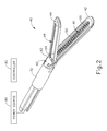
  • FIG. 2 depicts a perspective view of the end effector of the instrument of FIG. 1 , in an open configuration
  • FIG. 3 depicts another perspective view of the end effector of the instrument of FIG. 1 , in an open configuration
  • FIG. 4 depicts a cross-sectional end view, taken along line 4 - 4 of FIG. 3 , of the end effector of FIG. 2 , in a closed configuration and with the blade in a distal position
  • FIG. 5 depicts a partial perspective view of the distal end of an exemplary alternative firing beam suitable for incorporation in the instrument of FIG. 1 ;
  • FIG. 6 depicts a perspective view of an exemplary variation of the instrument of FIG. 1 ;
  • FIG. 7 depicts a detailed perspective view of a shaft assembly and knob of the instrument of FIG. 6 ;
  • FIG. 8A depicts a top view of the shaft assembly and knob of FIG. 7 in a first position, with an articulation section of the shaft assembly in an unarticulated position;
  • FIG. 8B depicts a top view of the shaft assembly and knob of FIG. 7 in the first position, with the articulation section articulated in a first direction;
  • FIG. 8C depicts a top view of the shaft assembly and knob of FIG. 7 in the first position, with the articulation section articulated in a second direction;
  • FIG. 9 depicts a perspective view of another exemplary variation of the instrument of FIG. 1 ;
  • FIG. 10 depicts a detailed top view of an articulation section of the instrument of FIG. 9 ;
  • FIG. 11 depicts a detailed perspective view of a shaft assembly and knob of the instrument of FIG. 9 ;
  • FIG. 12A depicts a top view of the shaft assembly and knob of FIG. 11 in a first rotational position
  • FIG. 12B depicts a top view of the shaft assembly and knob of FIG. 11 rotated to a second rotational position, which is 90° from the first rotational position, with the articulation section of FIG. 10 in an unarticulated position;
  • FIG. 12C depicts a top view of the shaft assembly and knob of FIG. 11 rotated to a third rotational position, which is 270° from the first rotational position, with the articulation section of FIG. 10 in an unarticulated position.
  • proximal and distal are defined herein relative to a surgeon or other operator grasping a surgical instrument having a distal surgical end effector.
  • proximal refers the position of an element closer to the surgeon or other operator and the term “distal” refers to the position of an element closer to the surgical end effector of the surgical instrument and further away from the surgeon or other operator.
  • FIGS. 1-4 show an exemplary electrosurgical instrument ( 10 ) that is constructed and operable in accordance with at least some of the teachings of U.S. Pat. No. 6,500,176; U.S. Pat. No. 7,112,201; U.S. Pat. No. 7,125,409; U.S. Pat. No. 7,169,146; U.S. Pat. No. 7,186,253; U.S. Pat. No. 7,189,233; U.S. Pat. No. 7,220,951; U.S. Pat. No. 7,309,849; U.S. Pat. No. 7,311,709; U.S. Pat. No. 7,354,440; U.S. Pat. No. 7,381,209; U.S. Pub.
  • electrosurgical instrument ( 10 ) is operable to cut tissue and seal or weld tissue (e.g., a blood vessel, etc.) substantially simultaneously.
  • electrosurgical instrument ( 10 ) operates similar to an endocutter type of stapler, except that electrosurgical instrument ( 10 ) provides tissue welding through application of bipolar RF energy instead of providing lines of staples to join tissue.
  • electrosurgical instrument ( 10 ) may have various structural and functional similarities with the ENSEAL® Tissue Sealing Device by Ethicon Endo-Surgery, Inc., of Cincinnati, Ohio.
  • electrosurgical instrument ( 10 ) may have various structural and functional similarities with the devices taught in any of the other references that are cited and incorporated by reference herein. To the extent that there is some degree of overlap between the teachings of the references cited herein, the ENSEAL® Tissue Sealing Device by Ethicon Endo-Surgery, Inc., of Cincinnati, Ohio, and the following teachings relating to electrosurgical instrument ( 10 ), there is no intent for any of the description herein to be presumed as admitted prior art. Several teachings below will in fact go beyond the scope of the teachings of the references cited herein and the ENSEAL® Tissue Sealing Device by Ethicon Endo-Surgery, Inc., of Cincinnati, Ohio.
  • Electrosurgical instrument ( 10 ) of the present example includes a handpiece ( 20 ), a shaft ( 30 ) extending distally from handpiece ( 20 ), and an end effector ( 40 ) disposed at a distal end of shaft ( 30 ).
  • Handpiece ( 20 ) of the present example includes a pistol grip ( 22 ), a pivoting trigger ( 24 ), an activation button ( 26 ), and an articulation control ( 28 ).
  • Trigger ( 24 ) is pivotable toward and away from pistol grip ( 22 ) to selectively actuate end effector ( 40 ) as will be described in greater detail below.
  • Activation button ( 26 ) is operable to selectively activate RF circuitry that is in communication with end effector ( 40 ), as will also be described in greater detail below.
  • activation button ( 26 ) also serves as a mechanical lockout against trigger ( 24 ), such that trigger ( 24 ) cannot be fully actuated unless button ( 26 ) is being pressed simultaneously. Examples of how such a lockout may be provided are disclosed in one or more of the references cited herein.
  • trigger ( 24 ) may serve as an electrical and/or mechanical lockout against button ( 26 ), such that button ( 26 ) cannot be effectively activated unless trigger ( 24 ) is being squeezed simultaneously.
  • pistol grip ( 22 ), trigger ( 24 ), and button ( 26 ) may be modified, substituted, supplemented, etc. in any suitable way, and that the descriptions of such components herein are merely illustrative.
  • Shaft ( 30 ) of the present example includes a rigid outer sheath ( 32 ) and an articulation section ( 36 ).
  • Articulation section ( 36 ) is operable to selectively laterally deflect end effector ( 40 ) at various angles relative to the longitudinal axis defined by sheath ( 32 ).
  • articulation section ( 36 ) and/or some other portion of outer sheath ( 32 ) includes a flexible outer sheath (e.g., a heat shrink tube, etc.) disposed about its exterior.
  • Articulation section ( 36 ) of shaft ( 30 ) may take a variety of forms.
  • articulation section ( 36 ) may be configured in accordance with one or more teachings of U.S. Pub. No.
  • articulation section ( 36 ) may be configured in accordance with one or more teachings of U.S. Pub. No. 2012/0078248, entitled “Articulation Joint Features for Articulating Surgical Device,” published Mar. 29, 2012, now U.S. Pat. No. 9,220,559, issued on Dec. 29, 2015, the disclosure of which is incorporated by reference herein.
  • Various other suitable forms that articulation section ( 36 ) may take will be apparent to those of ordinary skill in the art in view of the teachings herein. It should also be understood that some versions of instrument ( 10 ) may simply lack articulation section ( 36 ).
  • shaft ( 30 ) is also rotatable about the longitudinal axis defined by sheath ( 32 ), relative to handpiece ( 20 ), via a knob ( 34 ). Such rotation may provide rotation of end effector ( 40 ) and shaft ( 30 ) unitarily.
  • knob ( 34 ) is operable to rotate end effector ( 40 ) without rotating articulation section ( 36 ) or any portion of shaft ( 30 ) that is proximal of articulation section ( 36 ).
  • electrosurgical instrument ( 10 ) may include one rotation control that provides rotatability of shaft ( 30 ) and end effector ( 40 ) as a single unit; and another rotation control that provides rotatability of end effector ( 40 ) without rotating articulation section ( 36 ) or any portion of shaft ( 30 ) that is proximal of articulation section ( 36 ).
  • Other suitable rotation schemes will be apparent to those of ordinary skill in the art in view of the teachings herein.
  • rotatable features may simply be omitted if desired.
  • Articulation control ( 28 ) of the present example is operable to selectively control articulation section ( 36 ) of shaft ( 30 ), to thereby selectively laterally deflect end effector ( 40 ) at various angles relative to the longitudinal axis defined by shaft ( 30 ). While articulation control ( 28 ) is in the form of a rotary dial in the present example, it should be understood that articulation control ( 28 ) may take numerous other forms. By way of example only, some merely illustrative forms that articulation control ( 28 ) and other components of handpiece ( 20 ) may take are disclosed in U.S. Pub. No. 2012/0078243, the disclosure of which is incorporated by reference herein; in U.S. Pub. No.
  • End effector ( 40 ) of the present example comprises a first jaw ( 42 ) and a second jaw ( 44 ).
  • first jaw ( 42 ) is substantially fixed relative to shaft ( 30 ); while second jaw ( 44 ) pivots relative to shaft ( 30 ), toward and away from first jaw ( 42 ).
  • second jaw ( 44 ) pivots about an axis that is defined by a pin (or similar feature) that slides along an elongate slot or channel as second jaw ( 44 ) moves toward first jaw ( 42 ).
  • pivot axis translates along the path defined by the slot or channel while second jaw ( 44 ) simultaneously pivots about that axis.
  • sliding/translating pivotal movement is encompassed within terms such as “pivot,” “pivots,” “pivotal,” “pivotable,” “pivoting,” and the like.
  • some versions may provide pivotal movement of second jaw ( 44 ) about an axis that remains fixed and does not translate within a slot or channel, etc.
  • actuators such as rods or cables, etc.
  • jaws ( 42 , 44 ) may instead have any other suitable kind of movement and may be actuated in any other suitable fashion.
  • jaws ( 42 , 44 ) may be actuated and thus closed by longitudinal translation of a firing beam ( 60 ), such that actuator rods/cables/etc. may simply be eliminated in some versions.
  • first jaw ( 42 ) defines a longitudinally extending elongate slot ( 46 ); while second jaw ( 44 ) also defines a longitudinally extending elongate slot ( 48 ).
  • first electrode surface ( 50 ) presents a first electrode surface ( 50 ); while the underside of second jaw ( 44 ) presents a second electrode surface ( 52 ).
  • Electrode surfaces ( 50 , 52 ) are in communication with an electrical source ( 80 ) via one or more conductors (not shown) that extend along the length of shaft ( 30 ). These conductors are coupled with electrical source ( 80 ) and a controller ( 82 ) via a cable ( 84 ), which extends proximally from handpiece ( 20 ).
  • Electrical source ( 80 ) is operable to deliver RF energy to first electrode surface ( 50 ) at an active polarity while second electrode surface ( 52 ) serves as a reference/return passive electrode, such that RF current flows between electrode surfaces ( 50 , 52 ) and thereby through tissue captured between jaws ( 42 , 44 ).
  • firing beam ( 60 ) serves as an electrical conductor that cooperates with electrode surfaces ( 50 , 52 ) (e.g., as a ground return) for delivery of bipolar RF energy captured between jaws ( 42 , 44 ).
  • Electrical source ( 80 ) may be external to electrosurgical instrument ( 10 ) or may be integral with electrosurgical instrument ( 10 ) (e.g., in handpiece ( 20 ), etc.), as described in one or more references cited herein or otherwise.
  • a controller ( 82 ) regulates delivery of power from electrical source ( 80 ) to electrode surfaces ( 50 , 52 ). Controller ( 82 ) may also be external to electrosurgical instrument ( 10 ) or may be integral with electrosurgical instrument ( 10 ) (e.g., in handpiece ( 20 ), etc.), as described in one or more references cited herein or otherwise. It should also be understood that electrode surfaces ( 50 , 52 ) may be provided in a variety of alternative locations, configurations, and relationships.
  • power source ( 80 ) and/or controller ( 82 ) may be configured in accordance with at least some of the teachings of U.S. Provisional Pat. App. No. 61/550,768, entitled “Medical Instrument,” filed Oct. 24, 2011, the disclosure of which is incorporated by reference herein; U.S. Pub. No. 2011/0082486, entitled “Devices and Techniques for Cutting and Coagulating Tissue,” published Apr. 7, 2011, now U.S. Pat. No. 9,089,360, issued on Jul. 28, 2015, the disclosure of which is incorporated by reference herein; U.S. Pub. No. 2011/0087212, entitled “Surgical Generator for Ultrasonic and Electrosurgical Devices,” published Apr. 14, 2011 (now U.S. Pat.
  • first jaw ( 42 ) includes a longitudinally extending recess ( 58 ) adjacent to slot ( 46 ); while the upper side of second jaw ( 44 ) includes a longitudinally extending recess ( 59 ) adjacent to slot ( 48 ).
  • FIG. 2 shows the upper side of first jaw ( 42 ) including a plurality of teeth serrations ( 46 ).
  • the lower side of second jaw ( 44 ) may include complementary serrations that nest with serrations ( 46 ), to enhance gripping of tissue captured between jaws ( 42 , 44 ) without necessarily tearing the tissue.
  • serrations may be generally blunt or otherwise atraumatic.
  • serrations ( 46 ) in first jaw ( 42 ) as mainly recesses; with serrations ( 48 ) in second jaw ( 44 ) as mainly protrusions.
  • serrations ( 46 , 48 ) may take any other suitable form or may be simply omitted altogether.
  • serrations ( 46 , 48 ) may be formed of an electrically non-conductive, or insulative, material, such as plastic, glass, and/or ceramic, for example, and may include a treatment such as polytetrafluoroethylene, a lubricant, or some other treatment to substantially prevent tissue from getting stuck to jaws ( 42 , 44 ).
  • serrations ( 46 , 48 ) are electrically conductive.
  • shaft ( 30 ) and end effector ( 40 ) are sized and configured to fit through trocars having various inner diameters, such that electrosurgical instrument ( 10 ) is usable in minimally invasive surgery, though of course electrosurgical instrument ( 10 ) could also be used in open procedures if desired.
  • shaft ( 30 ) and end effector ( 40 ) may present an outer diameter of approximately 5 mm.
  • shaft ( 30 ) and end effector ( 40 ) may present any other suitable outer diameter (e.g., between approximately 2 mm and approximately 20 mm, etc.).
  • either jaw ( 42 , 44 ) or both of jaws ( 42 , 44 ) may include at least one port, passageway, conduit, and/or other feature that is operable to draw steam, smoke, and/or other gases/vapors/etc. from the surgical site.
  • a feature may be in communication with a source of suction, such as an external source or a source within handpiece ( 20 ), etc.
  • end effector ( 40 ) may include one or more tissue cooling features (not shown) that reduce the degree or extent of thermal spread caused by end effector ( 40 ) on adjacent tissue when electrode surfaces ( 50 , 52 ) are activated.
  • tissue cooling features not shown
  • end effector ( 40 ) includes one or more sensors (not shown) that are configured to sense a variety of parameters at end effector ( 40 ), including but not limited to temperature of adjacent tissue, electrical resistance or impedance of adjacent tissue, voltage across adjacent tissue, forces exerted on jaws ( 42 , 44 ) by adjacent tissue, etc.
  • end effector ( 40 ) may include one or more positive temperature coefficient (PTC) thermistor bodies ( 54 , 56 ) (e.g., PTC polymer, etc.), located adjacent to electrodes ( 50 , 52 ) and/or elsewhere.
  • PTC positive temperature coefficient
  • Controller ( 82 ) may process such data in a variety of ways.
  • controller ( 82 ) may modulate or otherwise change the RF energy being delivered to electrode surfaces ( 50 , 52 ), based at least in part on data acquired from one or more sensors at end effector ( 40 ).
  • controller ( 82 ) may alert the user to one or more conditions via an audio and/or visual feedback device (e.g., speaker, lights, display screen, etc.), based at least in part on data acquired from one or more sensors at end effector ( 40 ).
  • an audio and/or visual feedback device e.g., speaker, lights, display screen, etc.
  • some kinds of sensors need not necessarily be in communication with controller ( 82 ), and may simply provide a purely localized effect at end effector ( 40 ).
  • a PTC thermistor bodies ( 54 , 56 ) at end effector ( 40 ) may automatically reduce the energy delivery at electrode surfaces ( 50 , 52 ) as the temperature of the tissue and/or end effector ( 40 ) increases, thereby reducing the likelihood of overheating.
  • a PTC thermistor element is in series with power source ( 80 ) and electrode surface ( 50 , 52 ); and the PTC thermistor provides an increased impedance (reducing flow of current) in response to temperatures exceeding a threshold.
  • electrode surfaces ( 50 , 52 ) may be used as sensors (e.g., to sense tissue impedance, etc.).
  • electrosurgical instrument ( 10 ) Various kinds of sensors that may be incorporated into electrosurgical instrument ( 10 ) will be apparent to those of ordinary skill in the art in view of the teachings herein. Similarly various things that can be done with data from sensors, by controller ( 82 ) or otherwise, will be apparent to those of ordinary skill in the art in view of the teachings herein. Other suitable variations for end effector ( 40 ) will also be apparent to those of ordinary skill in the art in view of the teachings herein.
  • electrosurgical instrument ( 10 ) of the present example includes a firing beam ( 60 ) that is longitudinally movable along part of the length of end effector ( 40 ).
  • Firing beam ( 60 ) is coaxially positioned within shaft ( 30 ), extends along the length of shaft ( 30 ), and translates longitudinally within shaft ( 30 ) (including articulation section ( 36 ) in the present example), though it should be understood that firing beam ( 60 ) and shaft ( 30 ) may have any other suitable relationship.
  • a proximal end of firing beam ( 60 ) is secured to a firing tube or other structure within shaft ( 30 ); and the firing tube or other structure extends through the remainder of shaft ( 30 ) to handpiece ( 20 ) where it is driven by movement of trigger ( 24 ).
  • Firing beam ( 60 ) includes a sharp distal blade ( 64 ), an upper flange ( 62 ), and a lower flange ( 66 ). As best seen in FIG.
  • distal blade ( 64 ) extends through slots ( 46 , 48 ) of jaws ( 42 , 44 ), with upper flange ( 62 ) being located above jaw ( 44 ) in recess ( 59 ) and lower flange ( 66 ) being located below jaw ( 42 ) in recess ( 58 ).
  • the configuration of distal blade ( 64 ) and flanges ( 62 , 66 ) provides an “I-beam” type of cross section at the distal end of firing beam ( 60 ).
  • flanges ( 62 , 66 ) extend longitudinally only along a small portion of the length of firing beam ( 60 ) in the present example, it should be understood that flanges ( 62 , 66 ) may extend longitudinally along any suitable length of firing beam ( 60 ).
  • flanges ( 62 , 66 ) are positioned along the exterior of jaws ( 42 , 44 ), flanges ( 62 , 66 ) may alternatively be disposed in corresponding slots formed within jaws ( 42 , 44 ).
  • each jaw ( 42 , 44 ) may define a “T”-shaped slot, with parts of distal blade ( 64 ) being disposed in one vertical portion of each “T”-shaped slot and with flanges ( 62 , 66 ) being disposed in the horizontal portions of the “T”-shaped slots.
  • flanges 62 , 66
  • Distal blade ( 64 ) is substantially sharp, such that distal blade ( 64 ) will readily sever tissue that is captured between jaws ( 42 , 44 ). Distal blade ( 64 ) is also electrically grounded in the present example, providing a return path for RF energy as described elsewhere herein. In some other versions, distal blade ( 64 ) serves as an active electrode.
  • the “I-beam” type of configuration of firing beam ( 60 ) provides closure of jaws ( 42 , 44 ) as firing beam ( 60 ) is advanced distally.
  • flange ( 62 ) urges jaw ( 44 ) pivotally toward jaw ( 42 ) as firing beam ( 60 ) is advanced from a proximal position ( FIGS. 1-3 ) to a distal position ( FIG. 4 ), by bearing against recess ( 59 ) formed in jaw ( 44 ).
  • This closing effect on jaws ( 42 , 44 ) by firing beam ( 60 ) may occur before distal blade ( 64 ) reaches tissue captured between jaws ( 42 , 44 ).
  • firing beam ( 60 ) may reduce the force required to squeeze trigger ( 24 ) to actuate firing beam ( 60 ) through a full firing stroke.
  • firing beam ( 60 ) may have already overcome an initial resistance required to substantially close jaws ( 42 , 44 ) on tissue before encountering resistance from severing the tissue captured between jaws ( 42 , 44 ).
  • any other suitable staging may be provided.
  • flange ( 62 ) is configured to cam against a ramp feature at the proximal end of jaw ( 44 ) to open jaw ( 44 ) when firing beam ( 60 ) is retracted to a proximal position and to hold jaw ( 44 ) open when firing beam ( 60 ) remains at the proximal position.
  • This camming capability may facilitate use of end effector ( 40 ) to separate layers of tissue, to perform blunt dissections, etc., by forcing jaws ( 42 , 44 ) apart from a closed position.
  • jaws ( 42 , 44 ) are resiliently biased to an open position by a spring or other type of resilient feature.
  • jaws ( 42 , 44 ) close or open as firing beam ( 60 ) is translated in the present example
  • other versions may provide independent movement of jaws ( 42 , 44 ) and firing beam ( 60 ).
  • one or more cables, rods, beams, or other features may extend through shaft ( 30 ) to selectively actuate jaws ( 42 , 44 ) independently of firing beam ( 60 ).
  • Such jaw ( 42 , 44 ) actuation features may be separately controlled by a dedicated feature of handpiece ( 20 ).
  • jaw actuation features may be controlled by trigger ( 24 ) in addition to having trigger ( 24 ) control firing beam ( 60 ).
  • firing beam ( 60 ) may be resiliently biased to a proximal position, such that firing beam ( 60 ) retracts proximally when an operator relaxes their grip on trigger ( 24 ).
  • FIG. 5 shows an exemplary alternative firing beam ( 70 ), which may be readily substituted for firing beam ( 60 ).
  • firing beam ( 70 ) comprises a blade insert ( 94 ) that is interposed between two beam plates ( 90 , 92 ).
  • Blade insert ( 94 ) includes a sharp distal edge ( 96 ), such that blade insert ( 94 ) will readily sever tissue that is captured between jaws ( 42 , 44 ).
  • Sharp distal edge ( 96 ) is exposed by a proximally extending recess ( 93 ) formed in plates ( 90 , 92 ).
  • a set of pins ( 72 , 74 , 76 ) are transversely disposed in plates ( 90 , 92 ).
  • Pins ( 72 , 74 ) together effectively serve as substitutes for upper flange ( 62 ); while pin ( 76 ) effectively serves as a substitute for lower flange ( 66 ).
  • pins ( 72 , 74 ) bear against channel ( 59 ) of jaw ( 44 )
  • pin ( 76 ) bears against channel ( 58 ) of jaw ( 42 ), as firing beam ( 70 ) is translated distally through slots ( 46 , 48 ).
  • Pins ( 72 , 74 , 76 ) of the present example are further configured to rotate within plates ( 90 , 92 ), about the axes respectively defined by pins ( 72 , 74 , 76 ).
  • pins ( 72 , 74 , 76 ) may provide reduced friction with jaws ( 42 , 44 ), thereby reducing the force required to translate firing beam ( 70 ) distally and proximally in jaws ( 42 , 44 ).
  • Pin ( 72 ) is disposed in an angled elongate slot ( 98 ) formed through plates ( 90 , 92 ), such that pin ( 72 ) is translatable along slot ( 98 ).
  • pin ( 72 ) is disposed in the proximal portion of slot ( 98 ) as firing beam ( 70 ) is being translated distally.
  • firing beam ( 70 ) When firing beam ( 70 ) is translated proximally, pin ( 72 ) slides distally and upwardly in slot ( 98 ), increasing the vertical separation between pins ( 72 , 76 ), which in turn reduces the compressive forces applied by jaws ( 42 , 44 ) and thereby reduces the force required to retract firing beam ( 70 ).
  • Pins ( 72 , 74 , 76 ) may be pinged, upended, or otherwise configured to provide further retention in the body of firing beam ( 70 ).
  • firing beam ( 70 ) may have any other suitable configuration.
  • firing beam ( 70 ) may be configured in accordance with at least some of the teachings of U.S. Pub. No. 2012/0083783 (now U.S. Pat. No. 8,888,809), the disclosure of which is incorporated by reference herein.
  • end effector ( 40 ) is inserted into a patient via a trocar.
  • Articulation section ( 36 ) is substantially straight when end effector ( 40 ) and part of shaft ( 30 ) are inserted through the trocar.
  • Articulation control ( 28 ) may then be manipulated to pivot or flex articulation section ( 36 ) of shaft ( 30 ) in order to position end effector ( 40 ) at a desired position and orientation relative to an anatomical structure within the patient.
  • Two layers of tissue of the anatomical structure are then captured between jaws ( 42 , 44 ) by squeezing trigger ( 24 ) toward pistol grip ( 22 ).
  • Such layers of tissue may be part of the same natural lumen defining anatomical structure (e.g., blood vessel, portion of gastrointestinal tract, portion of reproductive system, etc.) in a patient.
  • one tissue layer may comprise the top portion of a blood vessel while the other tissue layer may comprise the bottom portion of the blood vessel, along the same region of length of the blood vessel (e.g., such that the fluid path through the blood vessel before use of electrosurgical instrument ( 10 ) is perpendicular to the longitudinal axis defined by end effector ( 40 ), etc.).
  • the lengths of jaws ( 42 , 44 ) may be oriented perpendicular to (or at least generally transverse to) the length of the blood vessel.
  • jaws ( 42 , 44 ) may be substantially clamping tissue before trigger ( 24 ) has swept through a full range of motion toward pistol grip ( 22 ), such that trigger ( 24 ) may continue pivoting toward pistol grip ( 22 ) through a subsequent range of motion after jaws ( 42 , 44 ) have substantially clamped on the tissue.
  • firing beam ( 60 ) continues to advance distally by the user squeezing trigger ( 24 ) further toward pistol grip ( 22 ).
  • distal blade ( 64 ) simultaneously severs the clamped tissue layers, resulting in separated upper layer portions being apposed with respective separated lower layer portions. In some versions, this results in a blood vessel being cut in a direction that is generally transverse to the length of the blood vessel. It should be understood that the presence of flanges ( 62 , 66 ) immediately above and below jaws ( 42 , 44 ), respectively, help keep jaws ( 42 , 44 ) in a closed and tightly clamping position.
  • flanges ( 62 , 66 ) help maintain a significantly compressive force between jaws ( 42 , 44 ).
  • bipolar RF energy is applied to the tissue through electrode surfaces ( 50 , 52 ) by the user depressing activation button ( 26 ).
  • a bipolar RF current flows through the compressed regions of severed tissue layer portions.
  • the bipolar RF energy delivered by power source ( 80 ) ultimately thermally welds the tissue layer portions on one side of firing beam ( 60 ) together and the tissue layer portions on the other side of firing beam ( 60 ) together.
  • the heat generated by activated electrode surfaces ( 50 , 52 ) can denature the collagen within the tissue layer portions and, in cooperation with clamping pressure provided by jaws ( 42 , 44 ), the denatured collagen can form a seal within the tissue layer portions.
  • the severed ends of the natural lumen defining anatomical structure are hemostatically sealed shut, such that the severed ends will not leak bodily fluids.
  • electrode surfaces ( 50 , 52 ) may be activated with bipolar RF energy before firing beam ( 60 ) even begins to translate distally and thus before the tissue is even severed.
  • timing may be provided in versions where button ( 26 ) serves as a mechanical lockout relative to trigger ( 24 ) in addition to serving as a switch between power source ( 80 ) and electrode surfaces ( 50 , 52 ).
  • button ( 26 ) serves as a mechanical lockout relative to trigger ( 24 ) in addition to serving as a switch between power source ( 80 ) and electrode surfaces ( 50 , 52 ).
  • Other suitable ways in which instrument ( 10 ) may be operable and operated will be apparent to those of ordinary skill in the art in view of the teachings herein.
  • having visual markings on articulation section ( 36 ) and/or on end effector ( 40 ) may enable the operator to receive real time visual feedback via an endoscopic viewing monitor, without having to divert their eyes from a display showing the view from the endoscope. Having visual markings on handpiece ( 20 ) may enable the operator to confirm that their manipulation of instrument ( 10 ) will be made in accordance with the desired effects at end effector ( 40 ).
  • Having visual markings on both handpiece ( 20 ) and a component that is within the endoscopic field of view may enable the operator to quickly visually correlate the orientation of features on handpiece ( 20 ) with the orientation of features within the endoscopic field of view.
  • articulation section examples described below may function substantially similar to articulation section ( 36 ) described above.
  • the articulation section examples described below are operable to selectively laterally deflect an end effector at various angles relative to a longitudinal axis defined by a sheath like sheath ( 32 ).
  • the knob examples described below may function substantially similar to knob ( 34 ) described above.
  • the knob examples described below are operable to selectively rotate a shaft, an articulation section, and/or an end effector about the longitudinal axis defined by a sheath like sheath ( 32 ).
  • Instrument ( 100 ) of this example includes a handpiece ( 120 ), a shaft ( 130 ) extending distally from handpiece ( 120 ), and an end effector ( 140 ) disposed at a distal end of shaft ( 130 ).
  • Shaft ( 130 ) of the present example includes a rigid outer sheath ( 132 ) and an articulation section ( 136 ).
  • End effector ( 140 ) of the present example functions substantially similar to end effector ( 40 ) described above except for the differences discussed below.
  • end effector ( 140 ) of the present example comprises a first jaw ( 142 ) and a second jaw ( 144 ).
  • First jaw ( 142 ) is substantially fixed relative to a shaft ( 130 ); while second jaw ( 144 ) pivots relative to shaft ( 130 ), toward and away from first jaw ( 142 ).
  • Handpiece ( 120 ) of the present example includes a pistol grip ( 122 ), a pivoting trigger ( 124 ), an activation button ( 126 ), an articulation control ( 128 ), and a knob ( 134 ).
  • Trigger ( 124 ) of the present example functions substantially similar to trigger ( 24 ) described above.
  • trigger ( 124 ) is pivotable toward and away from pistol grip ( 122 ) to selectively actuate end effector ( 140 ).
  • Activation button ( 126 ) of the present example functions substantially similar to activation button ( 26 ) described above.
  • activation button ( 126 ) is operable to selectively activate RF circuitry that is in communication with end effector ( 140 ).
  • Articulation control ( 128 ) of the present example functions substantially similar to articulation control ( 28 ) described above.
  • articulation control ( 128 ) of the present example is operable to selectively control articulation section ( 136 ) of shaft ( 130 ), to thereby selectively laterally deflect end effector ( 140 ) at various angles relative to the longitudinal axis defined by shaft ( 130 ).
  • Shaft ( 130 ) is rotatable about the longitudinal axis defined by sheath ( 132 ), relative to handpiece ( 120 ), via knob ( 134 ). Such rotation provides rotation of end effector ( 140 ) and shaft ( 130 ) unitarily.
  • knob ( 134 ) is operable to rotate end effector ( 140 ) without rotating articulation section ( 136 ) or any portion of shaft ( 130 ) that is proximal of articulation section ( 136 ).
  • Articulation section ( 136 ) of the present example functions substantially similar to articulation section ( 36 ) described above except for the differences discussed below.
  • articulation section ( 136 ) is operable to selectively laterally deflect end effector ( 140 ) at various angles relative to a longitudinal axis defined by a sheath ( 132 ).
  • articulation section ( 136 ) of the present example presents a first indication section ( 136 A) and a second indication section ( 136 B).
  • First indication section ( 136 A) comprises a first series of indicator markings ( 137 A).
  • Second indication section ( 136 B) comprises a second series of indicator markings ( 137 B).
  • Indicator markings ( 137 A, 137 B) of the present example each comprise a series of equally spaced lines disposed on ribs of first indication section ( 136 A) and second indication section ( 136 B).
  • the series of equally spaced lines of indicator markings ( 137 A, 137 B) are oriented such that each line of first series of indicator markings ( 137 A) corresponds to an opposing line of second series of indicator markings ( 137 B) such that first series of indicator markings ( 137 A) and second series of indicator markings ( 137 B) form a symmetric pattern.
  • the spacing between indicator markings ( 137 A, 137 B) is opposingly decreased or increased to indicate to an operator the direction in which articulation section ( 136 ) is articulated. For instance, as shown in FIG. 8B , articulation section ( 136 ) has been articulated toward indication section ( 136 A). Such articulation causes the spacing between the lines of indicator marking ( 137 A) to decrease and the spacing between the lines of indicator markings ( 137 B) to increase.
  • articulation section ( 136 ) has been articulated toward indication section ( 136 B).
  • Such articulation causes the spacing between the lines of indicator marking ( 137 B) to decrease and the spacing between the lines of indicator markings ( 137 A) to increase. Therefore, upon viewing the spacing of the lines of indicator markings ( 137 A, 137 B), an operator could readily confirm that articulation section ( 136 ) was articulated toward indication section ( 136 B); and further ascertain the degree of articulation.
  • indicator markings ( 137 A, 137 B) may provide ready visual confirmation of the articulated state of articulation section; and that indicator markings ( 137 A, 137 B) may further provide visual emphasis of the degree of articulation in articulation section ( 136 ).
  • indicator markings ( 137 A, 137 B) of the present example comprise a series of equally spaced lines, it should be understood that indicator markings ( 137 A, 137 B) may take any form as would be apparent to one of ordinary skill in the art according to the teachings herein.
  • Instrument ( 200 ) of this example includes a handpiece ( 220 ), a shaft ( 230 ) extending distally from handpiece ( 220 ), and an end effector ( 240 ) disposed at a distal end of shaft ( 230 ).
  • Shaft ( 230 ) of the present example includes a rigid outer sheath ( 232 ) and an articulation section ( 236 ).
  • End effector ( 240 ) of the present example functions substantially similar to end effector ( 40 ) described above.
  • end effector ( 240 ) of the present example comprises a first jaw ( 242 ) and a second jaw ( 244 ).
  • First jaw ( 242 ) is substantially fixed relative to a shaft ( 230 ); while second jaw ( 244 ) pivots relative to shaft ( 230 ), toward and away from first jaw ( 242 ).
  • Handpiece ( 220 ) of the present example includes a pistol grip ( 222 ), a pivoting trigger ( 224 ), an activation button ( 226 ), an articulation control ( 228 ), and a knob ( 234 ).
  • Trigger ( 224 ) of the present example functions substantially similar to trigger ( 24 ) described above.
  • trigger ( 224 ) is pivotable toward and away from pistol grip ( 222 ) to selectively actuate end effector ( 240 ).
  • Activation button ( 226 ) of the present example functions substantially similar to activation button ( 26 ) described above.
  • activation button ( 226 ) is operable to selectively activate RF circuitry that is in communication with end effector ( 240 ).
  • Articulation control ( 228 ) of the present example functions substantially similar to articulation control ( 28 ) described above.
  • articulation control ( 228 ) of the present example is operable to selectively control articulation section ( 236 ) of shaft ( 230 ), to thereby selectively laterally deflect end effector ( 240 ) at various angles relative to the longitudinal axis defined by shaft ( 230 ).
  • Shaft ( 230 ) is rotatable about the longitudinal axis defined by sheath ( 232 ), relative to handpiece ( 220 ), via knob ( 234 ). Such rotation provides rotation of end effector ( 240 ) and shaft ( 230 ) unitarily.
  • knob ( 234 ) is operable to rotate end effector ( 240 ) without rotating articulation section ( 236 ) or any portion of shaft ( 230 ) that is proximal of articulation section ( 236 ).
  • Articulation section ( 236 ) of the present example functions substantially similar to articulation section ( 36 ) described above except for the differences discussed below.
  • articulation section ( 236 ) is operable to selectively laterally deflect end effector ( 240 ) at various angles relative to a longitudinal axis defined by a sheath ( 232 ).
  • articulation section ( 236 ) of the present example presents a first indication section ( 236 A) and a second indication section ( 236 B).
  • Indication sections ( 236 A, 236 B) of articulation section ( 236 ) comprise different colors such that first indication section ( 236 A) comprises a first color and second indication section ( 236 B) comprises a second color.
  • articulation section ( 236 ) may have three indication sections that each extend through a range of approximately 120° about the perimeter of articulation section ( 236 ).
  • articulation section ( 236 ) may have four indication sections that each extend through a range of approximately 90° about the perimeter of articulation section ( 236 ).
  • Other suitable ways in which articulation section ( 236 ) may be divided into sectors by indication sections will be apparent to those of ordinary skill in the art in view of the teachings herein.
  • knob ( 234 ) of the present example presents a first indication section ( 234 A) and a second indication section ( 234 B).
  • Indication sections ( 234 A, 234 B) of knob ( 234 ) comprise different colors such that first indication section ( 234 A) comprises a first color and second indication section ( 234 B) comprises a second color.
  • the particular color of indication section ( 234 A) of knob ( 234 ) matches the particular color of indication section ( 236 A) of articulation section ( 236 ); and the particular color of indication section ( 234 B) of knob ( 234 ) matches the particular color of indication section ( 236 B) of articulation section ( 236 ).
  • indication section ( 234 A) of knob ( 234 ) is oriented such that indication section ( 234 A) of knob ( 234 ) aligns with indication sections ( 236 A) of articulation section ( 236 ); and indication section ( 234 B) of knob ( 234 ) is oriented such that indication section ( 234 B) of knob ( 234 ) aligns with indication sections ( 236 B) of articulation section ( 236 ).
  • Indication section ( 234 A) thus fully complements and corresponds with indication section ( 236 A); while indication section ( 234 B) fully complements and corresponds with indication section ( 236 B).
  • knob ( 234 ) may have three indication sections that each extend through a range of approximately 120° about the perimeter of knob ( 234 ). As another merely illustrative example, knob ( 234 ) may have four indication sections that each extend through a range of approximately 90° about the perimeter of knob ( 234 ).
  • Other suitable ways in which knob ( 234 ) may be divided into sectors by indication sections will be apparent to those of ordinary skill in the art in view of the teachings herein. It should be understood that variations in the number/arrangement of indication sections in knob ( 234 ) may be complemented by a corresponding number/arrangement of indication sections in articulation section ( 236 ).
  • indication sections ( 234 A, 234 B) of knob ( 234 ) will remain aligned with indication sections ( 236 A, 236 B) of articulation section ( 236 ) as knob ( 234 ), shaft ( 230 ), and end effector ( 240 ) are rotated unitarily by knob ( 234 ).
  • end effector ( 240 ) and articulation section ( 236 ) may be viewable on an external monitor (not shown) via an endoscopic camera (not shown).
  • knob ( 234 ) would be viewable outside a patient.
  • the operator will be able to readily understand the angular orientation of end effector ( 240 ) in relation to knob ( 234 ) by visually correlating viewable indication section(s) ( 236 A, 236 B) with indication section(s) ( 234 A, 234 B). This may further enable the operator to readily discern the direction in which articulation section ( 236 ) will rotate when the operator rotates knob ( 234 ).
  • indication sections ( 234 A, 234 B, 236 A, 236 B) of the present example particular colors may take any form and would be apparent to one of ordinary skill in the art according to the teachings herein.
  • indication sections ( 234 A, 234 B, 236 A, 236 B) may include visually distinguishable patterns and/or other readily distinguishable features.
  • any of the indication sections and/or indication markings discussed above could be combined with one another.
  • the series equally spaced lines of indicator markings ( 137 A, 137 B) discussed above could be combined with the particular colors of indication sections ( 234 A, 234 B, 236 A, 236 B).
  • Other suitable features that may be used to provide ready visual confirmation of states of operation of an instrument will be apparent to those of ordinary skill in the art in view of the teachings herein.
  • any of the versions of electrosurgical instrument ( 10 ) described herein may include various other features in addition to or in lieu of those described above.
  • any of the devices herein may also include one or more of the various features disclosed in any of the various references that are incorporated by reference herein.
  • any of the devices described herein may be modified to include a motor or other electrically powered device to drive an otherwise manually moved component.
  • Various examples of such modifications are described in U.S. Pub. No. 2012/0116379, entitled “Motor Driven Electrosurgical Device with mechanical and Electrical Feedback,” published May 10, 2012, now U.S. Pat. No. 9,161,803, Issued on Oct. 20, 2015, the disclosure of which is incorporated by reference herein.
  • Various other suitable ways in which a motor or other electrically powered device may be incorporated into any of the devices herein will be apparent to those of ordinary skill in the art in view of the teachings herein.
  • any of the devices described herein may be modified to contain most, if not all, of the required components within the medical device itself. More specifically, the devices described herein may be adapted to use an internal or attachable power source instead of requiring the device to be plugged into an external power source by a cable.
  • Various examples of how medical devices may be adapted to include a portable power source are disclosed in U.S. Provisional Application Ser. No. 61/410,603, filed Nov. 5, 2010, entitled “Energy-Based Surgical Instruments,” the disclosure of which is incorporated by reference herein.
  • Various other suitable ways in which a power source may be incorporated into any of the devices herein will be apparent to those of ordinary skill in the art in view of the teachings herein.
  • Versions of the devices described above may have application in conventional medical treatments and procedures conducted by a medical professional, as well as application in robotic-assisted medical treatments and procedures.
  • various teachings herein may be readily incorporated into a robotic surgical system such as the DAVINCITM system by Intuitive Surgical, Inc., of Sunnyvale, Calif.
  • DAVINCITM system by Intuitive Surgical, Inc., of Sunnyvale, Calif.
  • teachings herein may be readily combined with various teachings of U.S. Pat. No. 6,783,524, entitled “Robotic Surgical Tool with Ultrasound Cauterizing and Cutting Instrument,” published Aug. 31, 2004, the disclosure of which is incorporated by reference herein.
  • Versions described above may be designed to be disposed of after a single use, or they can be designed to be used multiple times. Versions may, in either or both cases, be reconditioned for reuse after at least one use. Reconditioning may include any combination of the steps of disassembly of the device, followed by cleaning or replacement of particular pieces, and subsequent reassembly. In particular, some versions of the device may be disassembled, and any number of the particular pieces or parts of the device may be selectively replaced or removed in any combination. Upon cleaning and/or replacement of particular parts, some versions of the device may be reassembled for subsequent use either at a reconditioning facility, or by an operator immediately prior to a procedure.
  • reconditioning of a device may utilize a variety of techniques for disassembly, cleaning/replacement, and reassembly. Use of such techniques, and the resulting reconditioned device, are all within the scope of the present application.
  • versions described herein may be sterilized before and/or after a procedure.
  • the device is placed in a closed and sealed container, such as a plastic or TYVEK bag.
  • the container and device may then be placed in a field of radiation that can penetrate the container, such as gamma radiation, x-rays, or high-energy electrons.
  • the radiation may kill bacteria on the device and in the container.
  • the sterilized device may then be stored in the sterile container for later use.
  • a device may also be sterilized using any other technique known in the art, including but not limited to beta or gamma radiation, ethylene oxide, or steam.

Abstract

An apparatus for operating on tissue has a body, an elongate shaft, and an end effector. The elongate shaft extends distally from the body. The elongate shaft has an articulation section that is operable to selectively deflect the end effector laterally relative to the elongate shaft. The articulation section presents a first indication section and a second indication section. The first and second indication section may be configured to visually indicate the direction and degree of articulation of the articulation section. The first and second indication section may alternatively be configured to indicate the angular orientation of the end effector about the longitudinal axis. The body may further comprise a knob that is operable to rotate the shaft about the longitudinal axis. The knob may include a third indication section and a fourth indication section that align with the first and the second indication sections of the articulation section, respectively.

Description

BACKGROUND
A variety of surgical instruments include a tissue cutting element and one or more elements that transmit radio frequency (RF) energy to tissue (e.g., to coagulate or seal the tissue). An example of such an electrosurgical instrument is the ENSEAL® Tissue Sealing Device by Ethicon Endo-Surgery, Inc., of Cincinnati, Ohio. Further examples of such devices and related concepts are disclosed in U.S. Pat. No. 6,500,176 entitled “Electrosurgical Systems and Techniques for Sealing Tissue,” issued Dec. 31, 2002, the disclosure of which is incorporated by reference herein; U.S. Pat. No. 7,112,201 entitled “Electrosurgical Instrument and Method of Use,” issued Sep. 26, 2006, the disclosure of which is incorporated by reference herein; U.S. Pat. No. 7,125,409, entitled “Electrosurgical Working End for Controlled Energy Delivery,” issued Oct. 24, 2006, the disclosure of which is incorporated by reference herein; U.S. Pat. No. 7,169,146 entitled “Electrosurgical Probe and Method of Use,” issued Jan. 30, 2007, the disclosure of which is incorporated by reference herein; U.S. Pat. No. 7,186,253, entitled “Electrosurgical Jaw Structure for Controlled Energy Delivery,” issued Mar. 6, 2007, the disclosure of which is incorporated by reference herein; U.S. Pat. No. 7,189,233, entitled “Electrosurgical Instrument,” issued Mar. 13, 2007, the disclosure of which is incorporated by reference herein; U.S. Pat. No. 7,220,951, entitled “Surgical Sealing Surfaces and Methods of Use,” issued May 22, 2007, the disclosure of which is incorporated by reference herein; U.S. Pat. No. 7,309,849, entitled “Polymer Compositions Exhibiting a PTC Property and Methods of Fabrication,” issued Dec. 18, 2007, the disclosure of which is incorporated by reference herein; U.S. Pat. No. 7,311,709, entitled “Electrosurgical Instrument and Method of Use,” issued Dec. 25, 2007, the disclosure of which is incorporated by reference herein; U.S. Pat. No. 7,354,440, entitled “Electrosurgical Instrument and Method of Use,” issued Apr. 8, 2008, the disclosure of which is incorporated by reference herein; U.S. Pat. No. 7,381,209, entitled “Electrosurgical Instrument,” issued Jun. 3, 2008, the disclosure of which is incorporated by reference herein.
Additional examples of electrosurgical cutting instruments and related concepts are disclosed in U.S. Pub. No. 2011/0087218, entitled “Surgical Instrument Comprising First and Second Drive Systems Actuatable by a Common Trigger Mechanism,” published Apr. 14, 2011 (now U.S. Pat. No. 8,939,974), the disclosure of which is incorporated by reference herein; U.S. Pub. No. 2012/0083783, entitled “Surgical Instrument with Jaw Member,” published Apr. 5, 2012 (now U.S. Pat. No. 8,888,809), the disclosure of which is incorporated by reference herein; U.S. Pub. No. 2012/0116379, entitled “Motor Driven Electrosurgical Device with Mechanical and Electrical Feedback,” published May 10, 2012, now U.S. Pat. No. 9,161,803, issued Oct. 20, 2015, the disclosure of which is incorporated by reference herein; U.S. Pub. No. 2012/0078243, entitled “Control Features for Articulating Surgical Device,” published Mar. 29, 2012, the disclosure of which is incorporated by reference herein; U.S. Pub. No. 2012/0078247, entitled “Articulation Joint Features for Articulating Surgical Device,” published Mar. 29, 2012, now U.S. Pat No. 9,402,682, issued Aug. 2, 2016, the disclosure of which is incorporated by reference herein; U.S. Pub. No. 2013/0030428, entitled “Surgical Instrument with Multi-Phase Trigger Bias,” published Jan. 31, 2013, now U.S. Pat. No. 9,089,237, issued on Jul. 28, 2015, the disclosure of which is incorporated by reference herein; and U.S. Pub. No. 2013/0023868, entitled “Surgical Instrument with Contained Dual Helix Actuator Assembly,” published Jan. 31, 2013, now U.S. Pat. No 9,545,253, issued on Jan. 17, 2017, the disclosure of which is incorporated by reference herein.
While a variety of surgical instruments have been made and used, it is believed that no one prior to the inventors has made or used the invention described in the appended claims.
BRIEF DESCRIPTION OF THE DRAWINGS
While the specification concludes with claims which particularly point out and distinctly claim this technology, it is believed this technology will be better understood from the following description of certain examples taken in conjunction with the accompanying drawings, in which like reference numerals identify the same elements and in which:
FIG. 1 depicts a side elevational view of an exemplary electrosurgical medical instrument;
FIG. 2 depicts a perspective view of the end effector of the instrument of FIG. 1, in an open configuration;
FIG. 3 depicts another perspective view of the end effector of the instrument of FIG. 1, in an open configuration;
FIG. 4 depicts a cross-sectional end view, taken along line 4-4 of FIG. 3, of the end effector of FIG. 2, in a closed configuration and with the blade in a distal position
FIG. 5 depicts a partial perspective view of the distal end of an exemplary alternative firing beam suitable for incorporation in the instrument of FIG. 1;
FIG. 6 depicts a perspective view of an exemplary variation of the instrument of FIG. 1;
FIG. 7 depicts a detailed perspective view of a shaft assembly and knob of the instrument of FIG. 6;
FIG. 8A depicts a top view of the shaft assembly and knob of FIG. 7 in a first position, with an articulation section of the shaft assembly in an unarticulated position;
FIG. 8B depicts a top view of the shaft assembly and knob of FIG. 7 in the first position, with the articulation section articulated in a first direction;
FIG. 8C depicts a top view of the shaft assembly and knob of FIG. 7 in the first position, with the articulation section articulated in a second direction;
FIG. 9 depicts a perspective view of another exemplary variation of the instrument of FIG. 1;
FIG. 10 depicts a detailed top view of an articulation section of the instrument of FIG. 9;
FIG. 11 depicts a detailed perspective view of a shaft assembly and knob of the instrument of FIG. 9;
FIG. 12A depicts a top view of the shaft assembly and knob of FIG. 11 in a first rotational position;
FIG. 12B depicts a top view of the shaft assembly and knob of FIG. 11 rotated to a second rotational position, which is 90° from the first rotational position, with the articulation section of FIG. 10 in an unarticulated position; and
FIG. 12C depicts a top view of the shaft assembly and knob of FIG. 11 rotated to a third rotational position, which is 270° from the first rotational position, with the articulation section of FIG. 10 in an unarticulated position.
The drawings are not intended to be limiting in any way, and it is contemplated that various embodiments of the technology may be carried out in a variety of other ways, including those not necessarily depicted in the drawings. The accompanying drawings incorporated in and forming a part of the specification illustrate several aspects of the present technology, and together with the description serve to explain the principles of the technology; it being understood, however, that this technology is not limited to the precise arrangements shown.
DETAILED DESCRIPTION
The following description of certain examples of the technology should not be used to limit its scope. Other examples, features, aspects, embodiments, and advantages of the technology will become apparent to those skilled in the art from the following description, which is by way of illustration, one of the best modes contemplated for carrying out the technology. As will be realized, the technology described herein is capable of other different and obvious aspects, all without departing from the technology. Accordingly, the drawings and descriptions should be regarded as illustrative in nature and not restrictive.
It is further understood that any one or more of the teachings, expressions, embodiments, examples, etc. described herein may be combined with any one or more of the other teachings, expressions, embodiments, examples, etc. that are described herein. The following-described teachings, expressions, embodiments, examples, etc. should therefore not be viewed in isolation relative to each other. Various suitable ways in which the teachings herein may be combined will be readily apparent to those of ordinary skill in the art in view of the teachings herein. Such modifications and variations are intended to be included within the scope of the claims.
For clarity of disclosure, the terms “proximal” and “distal” are defined herein relative to a surgeon or other operator grasping a surgical instrument having a distal surgical end effector. The term “proximal” refers the position of an element closer to the surgeon or other operator and the term “distal” refers to the position of an element closer to the surgical end effector of the surgical instrument and further away from the surgeon or other operator.
I. Exemplary Electrosurgical Device with Articulation Feature
FIGS. 1-4 show an exemplary electrosurgical instrument (10) that is constructed and operable in accordance with at least some of the teachings of U.S. Pat. No. 6,500,176; U.S. Pat. No. 7,112,201; U.S. Pat. No. 7,125,409; U.S. Pat. No. 7,169,146; U.S. Pat. No. 7,186,253; U.S. Pat. No. 7,189,233; U.S. Pat. No. 7,220,951; U.S. Pat. No. 7,309,849; U.S. Pat. No. 7,311,709; U.S. Pat. No. 7,354,440; U.S. Pat. No. 7,381,209; U.S. Pub. No. 2011/0087218 (now U.S. Pat. No. 8,939,974); U.S. Pub. No. 2012/0083783 (now U.S. Pat. No. 8,888,809); U.S. Pub. No. 2012/0116379, now U.S. Pat. No. 9,161,803, issued Oct. 20, 2015; U.S. Pub. No. 2012/0078243; U.S. Pub. No. 2012/0078247; now U.S. Pat. No. 9,402,682, issued Aug. 2, 2016; U.S. Pub. No. 2013/0030428; now U.S. Pat. No. 9,089,327, issued on Jul. 28, 2015; and/or U.S. Pub. No. 2013/0023868, now U.S. Pat. No. 9,545,253, issued on Jan. 17, 2017. As described therein and as will be described in greater detail below, electrosurgical instrument (10) is operable to cut tissue and seal or weld tissue (e.g., a blood vessel, etc.) substantially simultaneously. In other words, electrosurgical instrument (10) operates similar to an endocutter type of stapler, except that electrosurgical instrument (10) provides tissue welding through application of bipolar RF energy instead of providing lines of staples to join tissue. It should also be understood that electrosurgical instrument (10) may have various structural and functional similarities with the ENSEAL® Tissue Sealing Device by Ethicon Endo-Surgery, Inc., of Cincinnati, Ohio. Furthermore, electrosurgical instrument (10) may have various structural and functional similarities with the devices taught in any of the other references that are cited and incorporated by reference herein. To the extent that there is some degree of overlap between the teachings of the references cited herein, the ENSEAL® Tissue Sealing Device by Ethicon Endo-Surgery, Inc., of Cincinnati, Ohio, and the following teachings relating to electrosurgical instrument (10), there is no intent for any of the description herein to be presumed as admitted prior art. Several teachings below will in fact go beyond the scope of the teachings of the references cited herein and the ENSEAL® Tissue Sealing Device by Ethicon Endo-Surgery, Inc., of Cincinnati, Ohio.
A. Exemplary Handpiece and Shaft
Electrosurgical instrument (10) of the present example includes a handpiece (20), a shaft (30) extending distally from handpiece (20), and an end effector (40) disposed at a distal end of shaft (30). Handpiece (20) of the present example includes a pistol grip (22), a pivoting trigger (24), an activation button (26), and an articulation control (28). Trigger (24) is pivotable toward and away from pistol grip (22) to selectively actuate end effector (40) as will be described in greater detail below. Activation button (26) is operable to selectively activate RF circuitry that is in communication with end effector (40), as will also be described in greater detail below. In some versions, activation button (26) also serves as a mechanical lockout against trigger (24), such that trigger (24) cannot be fully actuated unless button (26) is being pressed simultaneously. Examples of how such a lockout may be provided are disclosed in one or more of the references cited herein. In addition or in the alternative, trigger (24) may serve as an electrical and/or mechanical lockout against button (26), such that button (26) cannot be effectively activated unless trigger (24) is being squeezed simultaneously. It should be understood that pistol grip (22), trigger (24), and button (26) may be modified, substituted, supplemented, etc. in any suitable way, and that the descriptions of such components herein are merely illustrative.
Shaft (30) of the present example includes a rigid outer sheath (32) and an articulation section (36). Articulation section (36) is operable to selectively laterally deflect end effector (40) at various angles relative to the longitudinal axis defined by sheath (32). In some versions, articulation section (36) and/or some other portion of outer sheath (32) includes a flexible outer sheath (e.g., a heat shrink tube, etc.) disposed about its exterior. Articulation section (36) of shaft (30) may take a variety of forms. By way of example only, articulation section (36) may be configured in accordance with one or more teachings of U.S. Pub. No. 2012/0078247, now U.S. Pat. No. 9,402,682, issued Aug. 2, 2016, the disclosure of which is incorporated by reference herein. As another merely illustrative example, articulation section (36) may be configured in accordance with one or more teachings of U.S. Pub. No. 2012/0078248, entitled “Articulation Joint Features for Articulating Surgical Device,” published Mar. 29, 2012, now U.S. Pat. No. 9,220,559, issued on Dec. 29, 2015, the disclosure of which is incorporated by reference herein. Various other suitable forms that articulation section (36) may take will be apparent to those of ordinary skill in the art in view of the teachings herein. It should also be understood that some versions of instrument (10) may simply lack articulation section (36).
In some versions, shaft (30) is also rotatable about the longitudinal axis defined by sheath (32), relative to handpiece (20), via a knob (34). Such rotation may provide rotation of end effector (40) and shaft (30) unitarily. In some other versions, knob (34) is operable to rotate end effector (40) without rotating articulation section (36) or any portion of shaft (30) that is proximal of articulation section (36). As another merely illustrative example, electrosurgical instrument (10) may include one rotation control that provides rotatability of shaft (30) and end effector (40) as a single unit; and another rotation control that provides rotatability of end effector (40) without rotating articulation section (36) or any portion of shaft (30) that is proximal of articulation section (36). Other suitable rotation schemes will be apparent to those of ordinary skill in the art in view of the teachings herein. Of course, rotatable features may simply be omitted if desired.
Articulation control (28) of the present example is operable to selectively control articulation section (36) of shaft (30), to thereby selectively laterally deflect end effector (40) at various angles relative to the longitudinal axis defined by shaft (30). While articulation control (28) is in the form of a rotary dial in the present example, it should be understood that articulation control (28) may take numerous other forms. By way of example only, some merely illustrative forms that articulation control (28) and other components of handpiece (20) may take are disclosed in U.S. Pub. No. 2012/0078243, the disclosure of which is incorporated by reference herein; in U.S. Pub. No. 2012/0078244, entitled “Control Features for Articulating Surgical Device,” published Mar. 29, 2012, the disclosure of which is incorporated by reference herein; and in U.S. Pub. No. 2013/0023868, now U.S. Pat. No. 9,545,253, issued on Jan. 17, 2017, the disclosure of which is incorporated by reference herein. Still other suitable forms that articulation control (28) may take will be apparent to those of ordinary skill in the art in view of the teachings herein. It should also be understood that some versions of instrument (10) may simply lack an articulation control (28).
B. Exemplary End Effector
End effector (40) of the present example comprises a first jaw (42) and a second jaw (44). In the present example, first jaw (42) is substantially fixed relative to shaft (30); while second jaw (44) pivots relative to shaft (30), toward and away from first jaw (42). Use of the term “pivot” should not be read as necessarily requiring pivotal movement about a fixed axis. In some versions, second jaw (44) pivots about an axis that is defined by a pin (or similar feature) that slides along an elongate slot or channel as second jaw (44) moves toward first jaw (42). In such versions, the pivot axis translates along the path defined by the slot or channel while second jaw (44) simultaneously pivots about that axis. It should be understood that such sliding/translating pivotal movement is encompassed within terms such as “pivot,” “pivots,” “pivotal,” “pivotable,” “pivoting,” and the like. Of course, some versions may provide pivotal movement of second jaw (44) about an axis that remains fixed and does not translate within a slot or channel, etc.
In some versions, actuators such as rods or cables, etc., may extend through sheath (32) and be joined with second jaw (44) at a pivotal coupling (43), such that longitudinal movement of the actuator rods/cables/etc. through shaft (30) provides pivoting of second jaw (44) relative to shaft (30) and relative to first jaw (42). Of course, jaws (42, 44) may instead have any other suitable kind of movement and may be actuated in any other suitable fashion. By way of example only, and as will be described in greater detail below, jaws (42, 44) may be actuated and thus closed by longitudinal translation of a firing beam (60), such that actuator rods/cables/etc. may simply be eliminated in some versions.
As best seen in FIGS. 2-4, first jaw (42) defines a longitudinally extending elongate slot (46); while second jaw (44) also defines a longitudinally extending elongate slot (48). In addition, the top side of first jaw (42) presents a first electrode surface (50); while the underside of second jaw (44) presents a second electrode surface (52). Electrode surfaces (50, 52) are in communication with an electrical source (80) via one or more conductors (not shown) that extend along the length of shaft (30). These conductors are coupled with electrical source (80) and a controller (82) via a cable (84), which extends proximally from handpiece (20). Electrical source (80) is operable to deliver RF energy to first electrode surface (50) at an active polarity while second electrode surface (52) serves as a reference/return passive electrode, such that RF current flows between electrode surfaces (50, 52) and thereby through tissue captured between jaws (42, 44). There are instances where the active signal crosses zero potential that the reference is at the same potential so there is no current flow. In some versions, firing beam (60) serves as an electrical conductor that cooperates with electrode surfaces (50, 52) (e.g., as a ground return) for delivery of bipolar RF energy captured between jaws (42, 44). Electrical source (80) may be external to electrosurgical instrument (10) or may be integral with electrosurgical instrument (10) (e.g., in handpiece (20), etc.), as described in one or more references cited herein or otherwise. A controller (82) regulates delivery of power from electrical source (80) to electrode surfaces (50, 52). Controller (82) may also be external to electrosurgical instrument (10) or may be integral with electrosurgical instrument (10) (e.g., in handpiece (20), etc.), as described in one or more references cited herein or otherwise. It should also be understood that electrode surfaces (50, 52) may be provided in a variety of alternative locations, configurations, and relationships.
By way of example only, power source (80) and/or controller (82) may be configured in accordance with at least some of the teachings of U.S. Provisional Pat. App. No. 61/550,768, entitled “Medical Instrument,” filed Oct. 24, 2011, the disclosure of which is incorporated by reference herein; U.S. Pub. No. 2011/0082486, entitled “Devices and Techniques for Cutting and Coagulating Tissue,” published Apr. 7, 2011, now U.S. Pat. No. 9,089,360, issued on Jul. 28, 2015, the disclosure of which is incorporated by reference herein; U.S. Pub. No. 2011/0087212, entitled “Surgical Generator for Ultrasonic and Electrosurgical Devices,” published Apr. 14, 2011 (now U.S. Pat. No. 8,986,302), the disclosure of which is incorporated by reference herein; U.S. Pub. No. 2011/0087213, entitled “Surgical Generator for Ultrasonic and Electrosurgical Devices,” published Apr. 14, 2011 (now U.S. Pat. No. 8,951,248), the disclosure of which is incorporated by reference herein; U.S. Pub. No. 2011/0087214, entitled “Surgical Generator for Ultrasonic and Electrosurgical Devices,” published Apr. 14, 2011, now U.S. Pat. No. 9,039,695, issued on May 26, 2015, the disclosure of which is incorporated by reference herein; U.S. Pub. No. 2011/0087215, entitled “Surgical Generator for Ultrasonic and Electrosurgical Devices,” published Apr. 14, 2011, now U.S. Pat. No. 9,050,093, issued on Jun. 9, 2015, the disclosure of which is incorporated by reference herein; U.S. Pub. No. 2011/0087216, entitled “Surgical Generator for Ultrasonic and Electrosurgical Devices,” published Apr. 14, 2011 (now U.S. Pat. No. 8,956,349), the disclosure of which is incorporated by reference herein; and/or U.S. Pub. No. 2011/0087217, entitled “Surgical Generator for Ultrasonic and Electrosurgical Devices,” published Apr. 14, 2011, now U.S. Pat. No. 9,060,776, issued on Jun. 23, 2015, the disclosure of which is incorporated by reference herein. Other suitable configurations for power source (80) and controller (82) will be apparent to those of ordinary skill in the art in view of the teachings herein.
As best seen in FIG. 4, the lower side of first jaw (42) includes a longitudinally extending recess (58) adjacent to slot (46); while the upper side of second jaw (44) includes a longitudinally extending recess (59) adjacent to slot (48). FIG. 2 shows the upper side of first jaw (42) including a plurality of teeth serrations (46). It should be understood that the lower side of second jaw (44) may include complementary serrations that nest with serrations (46), to enhance gripping of tissue captured between jaws (42, 44) without necessarily tearing the tissue. In other words, it should be understood that serrations may be generally blunt or otherwise atraumatic. FIG. 3 shows an example of serrations (46) in first jaw (42) as mainly recesses; with serrations (48) in second jaw (44) as mainly protrusions. Of course, serrations (46, 48) may take any other suitable form or may be simply omitted altogether. It should also be understood that serrations (46, 48) may be formed of an electrically non-conductive, or insulative, material, such as plastic, glass, and/or ceramic, for example, and may include a treatment such as polytetrafluoroethylene, a lubricant, or some other treatment to substantially prevent tissue from getting stuck to jaws (42, 44). In some versions, serrations (46, 48) are electrically conductive.
With jaws (42, 44) in a closed position, shaft (30) and end effector (40) are sized and configured to fit through trocars having various inner diameters, such that electrosurgical instrument (10) is usable in minimally invasive surgery, though of course electrosurgical instrument (10) could also be used in open procedures if desired. By way of example only, with jaws (42, 44) in a closed position, shaft (30) and end effector (40) may present an outer diameter of approximately 5 mm. Alternatively, shaft (30) and end effector (40) may present any other suitable outer diameter (e.g., between approximately 2 mm and approximately 20 mm, etc.).
As another merely illustrative variation, either jaw (42, 44) or both of jaws (42, 44) may include at least one port, passageway, conduit, and/or other feature that is operable to draw steam, smoke, and/or other gases/vapors/etc. from the surgical site. Such a feature may be in communication with a source of suction, such as an external source or a source within handpiece (20), etc. In addition, end effector (40) may include one or more tissue cooling features (not shown) that reduce the degree or extent of thermal spread caused by end effector (40) on adjacent tissue when electrode surfaces (50, 52) are activated. Various suitable forms that such cooling features may take will be apparent to those of ordinary skill in the art in view of the teachings herein.
In some versions, end effector (40) includes one or more sensors (not shown) that are configured to sense a variety of parameters at end effector (40), including but not limited to temperature of adjacent tissue, electrical resistance or impedance of adjacent tissue, voltage across adjacent tissue, forces exerted on jaws (42, 44) by adjacent tissue, etc. By way of example only, end effector (40) may include one or more positive temperature coefficient (PTC) thermistor bodies (54, 56) (e.g., PTC polymer, etc.), located adjacent to electrodes (50, 52) and/or elsewhere. Data from sensors may be communicated to controller (82). Controller (82) may process such data in a variety of ways. By way of example only, controller (82) may modulate or otherwise change the RF energy being delivered to electrode surfaces (50, 52), based at least in part on data acquired from one or more sensors at end effector (40). In addition or in the alternative, controller (82) may alert the user to one or more conditions via an audio and/or visual feedback device (e.g., speaker, lights, display screen, etc.), based at least in part on data acquired from one or more sensors at end effector (40). It should also be understood that some kinds of sensors need not necessarily be in communication with controller (82), and may simply provide a purely localized effect at end effector (40). For instance, a PTC thermistor bodies (54, 56) at end effector (40) may automatically reduce the energy delivery at electrode surfaces (50, 52) as the temperature of the tissue and/or end effector (40) increases, thereby reducing the likelihood of overheating. In some such versions, a PTC thermistor element is in series with power source (80) and electrode surface (50, 52); and the PTC thermistor provides an increased impedance (reducing flow of current) in response to temperatures exceeding a threshold. Furthermore, it should be understood that electrode surfaces (50, 52) may be used as sensors (e.g., to sense tissue impedance, etc.). Various kinds of sensors that may be incorporated into electrosurgical instrument (10) will be apparent to those of ordinary skill in the art in view of the teachings herein. Similarly various things that can be done with data from sensors, by controller (82) or otherwise, will be apparent to those of ordinary skill in the art in view of the teachings herein. Other suitable variations for end effector (40) will also be apparent to those of ordinary skill in the art in view of the teachings herein.
C. Exemplary Firing Beam
As also seen in FIGS. 2-4, electrosurgical instrument (10) of the present example includes a firing beam (60) that is longitudinally movable along part of the length of end effector (40). Firing beam (60) is coaxially positioned within shaft (30), extends along the length of shaft (30), and translates longitudinally within shaft (30) (including articulation section (36) in the present example), though it should be understood that firing beam (60) and shaft (30) may have any other suitable relationship. In some versions, a proximal end of firing beam (60) is secured to a firing tube or other structure within shaft (30); and the firing tube or other structure extends through the remainder of shaft (30) to handpiece (20) where it is driven by movement of trigger (24). Firing beam (60) includes a sharp distal blade (64), an upper flange (62), and a lower flange (66). As best seen in FIG. 4, distal blade (64) extends through slots (46, 48) of jaws (42, 44), with upper flange (62) being located above jaw (44) in recess (59) and lower flange (66) being located below jaw (42) in recess (58). The configuration of distal blade (64) and flanges (62, 66) provides an “I-beam” type of cross section at the distal end of firing beam (60). While flanges (62, 66) extend longitudinally only along a small portion of the length of firing beam (60) in the present example, it should be understood that flanges (62, 66) may extend longitudinally along any suitable length of firing beam (60). In addition, while flanges (62, 66) are positioned along the exterior of jaws (42, 44), flanges (62, 66) may alternatively be disposed in corresponding slots formed within jaws (42, 44). For instance, each jaw (42, 44) may define a “T”-shaped slot, with parts of distal blade (64) being disposed in one vertical portion of each “T”-shaped slot and with flanges (62, 66) being disposed in the horizontal portions of the “T”-shaped slots. Various other suitable configurations and relationships will be apparent to those of ordinary skill in the art in view of the teachings herein.
Distal blade (64) is substantially sharp, such that distal blade (64) will readily sever tissue that is captured between jaws (42, 44). Distal blade (64) is also electrically grounded in the present example, providing a return path for RF energy as described elsewhere herein. In some other versions, distal blade (64) serves as an active electrode.
The “I-beam” type of configuration of firing beam (60) provides closure of jaws (42, 44) as firing beam (60) is advanced distally. In particular, flange (62) urges jaw (44) pivotally toward jaw (42) as firing beam (60) is advanced from a proximal position (FIGS. 1-3) to a distal position (FIG. 4), by bearing against recess (59) formed in jaw (44). This closing effect on jaws (42, 44) by firing beam (60) may occur before distal blade (64) reaches tissue captured between jaws (42, 44). Such staging of encounters by firing beam (60) may reduce the force required to squeeze trigger (24) to actuate firing beam (60) through a full firing stroke. In other words, in some such versions, firing beam (60) may have already overcome an initial resistance required to substantially close jaws (42, 44) on tissue before encountering resistance from severing the tissue captured between jaws (42, 44). Of course, any other suitable staging may be provided.
In the present example, flange (62) is configured to cam against a ramp feature at the proximal end of jaw (44) to open jaw (44) when firing beam (60) is retracted to a proximal position and to hold jaw (44) open when firing beam (60) remains at the proximal position. This camming capability may facilitate use of end effector (40) to separate layers of tissue, to perform blunt dissections, etc., by forcing jaws (42, 44) apart from a closed position. In some other versions, jaws (42, 44) are resiliently biased to an open position by a spring or other type of resilient feature. While jaws (42, 44) close or open as firing beam (60) is translated in the present example, it should be understood that other versions may provide independent movement of jaws (42, 44) and firing beam (60). By way of example only, one or more cables, rods, beams, or other features may extend through shaft (30) to selectively actuate jaws (42, 44) independently of firing beam (60). Such jaw (42, 44) actuation features may be separately controlled by a dedicated feature of handpiece (20). Alternatively, such jaw actuation features may be controlled by trigger (24) in addition to having trigger (24) control firing beam (60). It should also be understood that firing beam (60) may be resiliently biased to a proximal position, such that firing beam (60) retracts proximally when an operator relaxes their grip on trigger (24).
FIG. 5 shows an exemplary alternative firing beam (70), which may be readily substituted for firing beam (60). In this example, firing beam (70) comprises a blade insert (94) that is interposed between two beam plates (90, 92). Blade insert (94) includes a sharp distal edge (96), such that blade insert (94) will readily sever tissue that is captured between jaws (42, 44). Sharp distal edge (96) is exposed by a proximally extending recess (93) formed in plates (90, 92). A set of pins (72, 74, 76) are transversely disposed in plates (90, 92). Pins (72, 74) together effectively serve as substitutes for upper flange (62); while pin (76) effectively serves as a substitute for lower flange (66). Thus, pins (72, 74) bear against channel (59) of jaw (44), and pin (76) bears against channel (58) of jaw (42), as firing beam (70) is translated distally through slots (46, 48). Pins (72, 74, 76) of the present example are further configured to rotate within plates (90, 92), about the axes respectively defined by pins (72, 74, 76). It should be understood that such rotatability of pins (72, 74, 76) may provide reduced friction with jaws (42, 44), thereby reducing the force required to translate firing beam (70) distally and proximally in jaws (42, 44). Pin (72) is disposed in an angled elongate slot (98) formed through plates (90, 92), such that pin (72) is translatable along slot (98). In particular, pin (72) is disposed in the proximal portion of slot (98) as firing beam (70) is being translated distally. When firing beam (70) is translated proximally, pin (72) slides distally and upwardly in slot (98), increasing the vertical separation between pins (72, 76), which in turn reduces the compressive forces applied by jaws (42, 44) and thereby reduces the force required to retract firing beam (70). Pins (72, 74, 76) may be pinged, upended, or otherwise configured to provide further retention in the body of firing beam (70). Of course, firing beam (70) may have any other suitable configuration. By way of example only, firing beam (70) may be configured in accordance with at least some of the teachings of U.S. Pub. No. 2012/0083783 (now U.S. Pat. No. 8,888,809), the disclosure of which is incorporated by reference herein.
D. Exemplary Operation
In an exemplary use, end effector (40) is inserted into a patient via a trocar. Articulation section (36) is substantially straight when end effector (40) and part of shaft (30) are inserted through the trocar. Articulation control (28) may then be manipulated to pivot or flex articulation section (36) of shaft (30) in order to position end effector (40) at a desired position and orientation relative to an anatomical structure within the patient. Two layers of tissue of the anatomical structure are then captured between jaws (42, 44) by squeezing trigger (24) toward pistol grip (22). Such layers of tissue may be part of the same natural lumen defining anatomical structure (e.g., blood vessel, portion of gastrointestinal tract, portion of reproductive system, etc.) in a patient. For instance, one tissue layer may comprise the top portion of a blood vessel while the other tissue layer may comprise the bottom portion of the blood vessel, along the same region of length of the blood vessel (e.g., such that the fluid path through the blood vessel before use of electrosurgical instrument (10) is perpendicular to the longitudinal axis defined by end effector (40), etc.). In other words, the lengths of jaws (42, 44) may be oriented perpendicular to (or at least generally transverse to) the length of the blood vessel. As noted above, flanges (62, 66) cammingly act to pivot jaw (42) toward jaw (44) when firing beam (60) is actuated distally by squeezing trigger (24) toward pistol grip (22). Jaws (42, 44) may be substantially clamping tissue before trigger (24) has swept through a full range of motion toward pistol grip (22), such that trigger (24) may continue pivoting toward pistol grip (22) through a subsequent range of motion after jaws (42, 44) have substantially clamped on the tissue.
With tissue layers captured between jaws (42, 44) firing beam (60) continues to advance distally by the user squeezing trigger (24) further toward pistol grip (22). As firing beam (60) continues to advance distally, distal blade (64) simultaneously severs the clamped tissue layers, resulting in separated upper layer portions being apposed with respective separated lower layer portions. In some versions, this results in a blood vessel being cut in a direction that is generally transverse to the length of the blood vessel. It should be understood that the presence of flanges (62, 66) immediately above and below jaws (42, 44), respectively, help keep jaws (42, 44) in a closed and tightly clamping position. In particular, flanges (62, 66) help maintain a significantly compressive force between jaws (42, 44). With severed tissue layer portions being compressed between jaws (42, 44), bipolar RF energy is applied to the tissue through electrode surfaces (50, 52) by the user depressing activation button (26). Thus, a bipolar RF current flows through the compressed regions of severed tissue layer portions. The bipolar RF energy delivered by power source (80) ultimately thermally welds the tissue layer portions on one side of firing beam (60) together and the tissue layer portions on the other side of firing beam (60) together.
In certain circumstances, the heat generated by activated electrode surfaces (50, 52) can denature the collagen within the tissue layer portions and, in cooperation with clamping pressure provided by jaws (42, 44), the denatured collagen can form a seal within the tissue layer portions. Thus, the severed ends of the natural lumen defining anatomical structure are hemostatically sealed shut, such that the severed ends will not leak bodily fluids. In some versions, electrode surfaces (50, 52) may be activated with bipolar RF energy before firing beam (60) even begins to translate distally and thus before the tissue is even severed. For instance, such timing may be provided in versions where button (26) serves as a mechanical lockout relative to trigger (24) in addition to serving as a switch between power source (80) and electrode surfaces (50, 52). Other suitable ways in which instrument (10) may be operable and operated will be apparent to those of ordinary skill in the art in view of the teachings herein.
II. Exemplary Alternative Electrosurgical Instrument
In some instances, it may be desirable to provide visual emphasis of the degree of articulation in an articulation section (36). It may also be desirable to indicate to an operator the direction in which articulation section (36) is articulated during operation, the degree to which articulation section (36) is articulated, and/or the manner in which end effector (36) will rotate when knob (34) is rotated. This may be particularly desirable when the operator wishes to rotate end effector (40) via knob (34) while articulation section (36) is in an articulated state. Indications may be provided to the operator through visual markings on handpiece (20), on articulation section (36), and/or on end effector (40). In settings where instrument (10) is being used in a minimally invasive procedure under endoscopic guidance, having visual markings on articulation section (36) and/or on end effector (40) may enable the operator to receive real time visual feedback via an endoscopic viewing monitor, without having to divert their eyes from a display showing the view from the endoscope. Having visual markings on handpiece (20) may enable the operator to confirm that their manipulation of instrument (10) will be made in accordance with the desired effects at end effector (40). Having visual markings on both handpiece (20) and a component that is within the endoscopic field of view (e.g., articulation section (36) and/or on end effector (40)) may enable the operator to quickly visually correlate the orientation of features on handpiece (20) with the orientation of features within the endoscopic field of view.
Various examples of how features of instrument (10) may be configured to provide visual feedback as indicated above will be described in greater detail; while still other examples will be apparent to those of ordinary skill in the art according to the teachings herein. It should be understood that the articulation section examples described below may function substantially similar to articulation section (36) described above. In particular, the articulation section examples described below are operable to selectively laterally deflect an end effector at various angles relative to a longitudinal axis defined by a sheath like sheath (32). It should also be understood that the knob examples described below may function substantially similar to knob (34) described above. In particular, the knob examples described below are operable to selectively rotate a shaft, an articulation section, and/or an end effector about the longitudinal axis defined by a sheath like sheath (32).
A. Exemplary Articulation Section Indicators
One merely exemplary variation of an electrosurgical instrument (100) is shown in FIG. 6. Instrument (100) of this example includes a handpiece (120), a shaft (130) extending distally from handpiece (120), and an end effector (140) disposed at a distal end of shaft (130). Shaft (130) of the present example includes a rigid outer sheath (132) and an articulation section (136). End effector (140) of the present example functions substantially similar to end effector (40) described above except for the differences discussed below. In particular, end effector (140) of the present example comprises a first jaw (142) and a second jaw (144). First jaw (142) is substantially fixed relative to a shaft (130); while second jaw (144) pivots relative to shaft (130), toward and away from first jaw (142).
Handpiece (120) of the present example includes a pistol grip (122), a pivoting trigger (124), an activation button (126), an articulation control (128), and a knob (134). Trigger (124) of the present example functions substantially similar to trigger (24) described above. In particular, trigger (124) is pivotable toward and away from pistol grip (122) to selectively actuate end effector (140). Activation button (126) of the present example functions substantially similar to activation button (26) described above. In particular, activation button (126) is operable to selectively activate RF circuitry that is in communication with end effector (140). Articulation control (128) of the present example functions substantially similar to articulation control (28) described above. In particular, articulation control (128) of the present example is operable to selectively control articulation section (136) of shaft (130), to thereby selectively laterally deflect end effector (140) at various angles relative to the longitudinal axis defined by shaft (130). Shaft (130) is rotatable about the longitudinal axis defined by sheath (132), relative to handpiece (120), via knob (134). Such rotation provides rotation of end effector (140) and shaft (130) unitarily. In some other versions, knob (134) is operable to rotate end effector (140) without rotating articulation section (136) or any portion of shaft (130) that is proximal of articulation section (136).
Articulation section (136) of the present example functions substantially similar to articulation section (36) described above except for the differences discussed below. In particular, articulation section (136) is operable to selectively laterally deflect end effector (140) at various angles relative to a longitudinal axis defined by a sheath (132). As shown in greater detail in FIG. 7, articulation section (136) of the present example presents a first indication section (136A) and a second indication section (136B). First indication section (136A) comprises a first series of indicator markings (137A). Second indication section (136B) comprises a second series of indicator markings (137B). Indicator markings (137A, 137B) of the present example each comprise a series of equally spaced lines disposed on ribs of first indication section (136A) and second indication section (136B). As best seen in FIG. 8A, the series of equally spaced lines of indicator markings (137A, 137B) are oriented such that each line of first series of indicator markings (137A) corresponds to an opposing line of second series of indicator markings (137B) such that first series of indicator markings (137A) and second series of indicator markings (137B) form a symmetric pattern.
When articulation section (136) is in a straight, non-articulated configuration as shown in FIG. 8A, the spacing between markings (137A) is equal to the spacing between markings (137B). Thus, by seeing the consistency between the spacing of markings (137A) and markings (137B) on an endoscopic viewing monitor, an operator will receive visual confirmation that articulation section (136) is in a straight, non-articulated configuration, without having to divert their eyes from the view of the surgical field on the endoscopic viewing monitor. As shown in FIGS. 8B-8C, depending upon the direction in which articulation section (136) is articulated, the spacing between indicator markings (137A, 137B) is opposingly decreased or increased to indicate to an operator the direction in which articulation section (136) is articulated. For instance, as shown in FIG. 8B, articulation section (136) has been articulated toward indication section (136A). Such articulation causes the spacing between the lines of indicator marking (137A) to decrease and the spacing between the lines of indicator markings (137B) to increase. Therefore, upon viewing the spacing of the lines of indicator markings (137A, 137B), an operator could readily confirm that articulation section (136) was articulated toward indication section (136A); and further ascertain the degree of articulation. Alternatively, as shown in FIG. 8C, articulation section (136) has been articulated toward indication section (136B). Such articulation causes the spacing between the lines of indicator marking (137B) to decrease and the spacing between the lines of indicator markings (137A) to increase. Therefore, upon viewing the spacing of the lines of indicator markings (137A, 137B), an operator could readily confirm that articulation section (136) was articulated toward indication section (136B); and further ascertain the degree of articulation.
It should be understood from the foregoing that indicator markings (137A, 137B) may provide ready visual confirmation of the articulated state of articulation section; and that indicator markings (137A, 137B) may further provide visual emphasis of the degree of articulation in articulation section (136). Although indicator markings (137A, 137B) of the present example comprise a series of equally spaced lines, it should be understood that indicator markings (137A, 137B) may take any form as would be apparent to one of ordinary skill in the art according to the teachings herein.
B. Exemplary Articulation Section and Knob Indicators
Another merely exemplary variation of an electrosurgical instrument (200) is shown in FIG. 9. Instrument (200) of this example includes a handpiece (220), a shaft (230) extending distally from handpiece (220), and an end effector (240) disposed at a distal end of shaft (230). Shaft (230) of the present example includes a rigid outer sheath (232) and an articulation section (236). End effector (240) of the present example functions substantially similar to end effector (40) described above. In particular, end effector (240) of the present example comprises a first jaw (242) and a second jaw (244). First jaw (242) is substantially fixed relative to a shaft (230); while second jaw (244) pivots relative to shaft (230), toward and away from first jaw (242).
Handpiece (220) of the present example includes a pistol grip (222), a pivoting trigger (224), an activation button (226), an articulation control (228), and a knob (234). Trigger (224) of the present example functions substantially similar to trigger (24) described above. In particular, trigger (224) is pivotable toward and away from pistol grip (222) to selectively actuate end effector (240). Activation button (226) of the present example functions substantially similar to activation button (26) described above. In particular, activation button (226) is operable to selectively activate RF circuitry that is in communication with end effector (240). Articulation control (228) of the present example functions substantially similar to articulation control (28) described above. In particular, articulation control (228) of the present example is operable to selectively control articulation section (236) of shaft (230), to thereby selectively laterally deflect end effector (240) at various angles relative to the longitudinal axis defined by shaft (230). Shaft (230) is rotatable about the longitudinal axis defined by sheath (232), relative to handpiece (220), via knob (234). Such rotation provides rotation of end effector (240) and shaft (230) unitarily. In some other versions, knob (234) is operable to rotate end effector (240) without rotating articulation section (236) or any portion of shaft (230) that is proximal of articulation section (236).
Articulation section (236) of the present example functions substantially similar to articulation section (36) described above except for the differences discussed below. In particular, articulation section (236) is operable to selectively laterally deflect end effector (240) at various angles relative to a longitudinal axis defined by a sheath (232). As shown in greater detail in FIG. 10, articulation section (236) of the present example presents a first indication section (236A) and a second indication section (236B). Indication sections (236A, 236B) of articulation section (236) comprise different colors such that first indication section (236A) comprises a first color and second indication section (236B) comprises a second color. While only two indication sections (236A, 236B) are used in the present example, it should be understood that any other suitable number of indication sections may be used. By way of example only, articulation section (236) may have three indication sections that each extend through a range of approximately 120° about the perimeter of articulation section (236). As another merely illustrative example, articulation section (236) may have four indication sections that each extend through a range of approximately 90° about the perimeter of articulation section (236). Other suitable ways in which articulation section (236) may be divided into sectors by indication sections will be apparent to those of ordinary skill in the art in view of the teachings herein.
As best seen in FIG. 11, knob (234) of the present example presents a first indication section (234A) and a second indication section (234B). Indication sections (234A, 234B) of knob (234) comprise different colors such that first indication section (234A) comprises a first color and second indication section (234B) comprises a second color. In the present example, the particular color of indication section (234A) of knob (234) matches the particular color of indication section (236A) of articulation section (236); and the particular color of indication section (234B) of knob (234) matches the particular color of indication section (236B) of articulation section (236). Also in the present example, indication section (234A) of knob (234) is oriented such that indication section (234A) of knob (234) aligns with indication sections (236A) of articulation section (236); and indication section (234B) of knob (234) is oriented such that indication section (234B) of knob (234) aligns with indication sections (236B) of articulation section (236). Indication section (234A) thus fully complements and corresponds with indication section (236A); while indication section (234B) fully complements and corresponds with indication section (236B).
While only two indication sections (234A, 234B) are used in the present example, it should be understood that any other suitable number of indication sections may be used. By way of example only, knob (234) may have three indication sections that each extend through a range of approximately 120° about the perimeter of knob (234). As another merely illustrative example, knob (234) may have four indication sections that each extend through a range of approximately 90° about the perimeter of knob (234). Other suitable ways in which knob (234) may be divided into sectors by indication sections will be apparent to those of ordinary skill in the art in view of the teachings herein. It should be understood that variations in the number/arrangement of indication sections in knob (234) may be complemented by a corresponding number/arrangement of indication sections in articulation section (236).
As shown in FIGS. 12A-12C, in versions of instrument (200) in which knob (234) is operable to rotate end effector (240) and shaft (230) unitarily, indication sections (234A, 234B) of knob (234) will remain aligned with indication sections (236A, 236B) of articulation section (236) as knob (234), shaft (230), and end effector (240) are rotated unitarily by knob (234). It should be understood that, during operation, end effector (240) and articulation section (236) may be viewable on an external monitor (not shown) via an endoscopic camera (not shown). It should also be understood that, during operation, knob (234) would be viewable outside a patient. Thus, if the operator wishes to rotate end effector (240) while end effector (240) is positioned within the patient, the operator will be able to readily understand the angular orientation of end effector (240) in relation to knob (234) by visually correlating viewable indication section(s) (236A, 236B) with indication section(s) (234A, 234B). This may further enable the operator to readily discern the direction in which articulation section (236) will rotate when the operator rotates knob (234).
Although indication sections (234A, 234B, 236A, 236B) of the present example particular colors, it should be understood that indication sections (234A, 234B, 236A, 236B) may take any form and would be apparent to one of ordinary skill in the art according to the teachings herein. By way of example only, indication sections (234A, 234B, 236A, 236B) may include visually distinguishable patterns and/or other readily distinguishable features. It should be understood that any of the indication sections and/or indication markings discussed above could be combined with one another. For instance, the series equally spaced lines of indicator markings (137A, 137B) discussed above could be combined with the particular colors of indication sections (234A, 234B, 236A, 236B). Other suitable features that may be used to provide ready visual confirmation of states of operation of an instrument will be apparent to those of ordinary skill in the art in view of the teachings herein.
III. Miscellaneous
It should be understood that any of the versions of electrosurgical instrument (10) described herein may include various other features in addition to or in lieu of those described above. By way of example only, any of the devices herein may also include one or more of the various features disclosed in any of the various references that are incorporated by reference herein.
It should also be understood that any of the devices described herein may be modified to include a motor or other electrically powered device to drive an otherwise manually moved component. Various examples of such modifications are described in U.S. Pub. No. 2012/0116379, entitled “Motor Driven Electrosurgical Device with mechanical and Electrical Feedback,” published May 10, 2012, now U.S. Pat. No. 9,161,803, Issued on Oct. 20, 2015, the disclosure of which is incorporated by reference herein. Various other suitable ways in which a motor or other electrically powered device may be incorporated into any of the devices herein will be apparent to those of ordinary skill in the art in view of the teachings herein.
It should also be understood that any of the devices described herein may be modified to contain most, if not all, of the required components within the medical device itself. More specifically, the devices described herein may be adapted to use an internal or attachable power source instead of requiring the device to be plugged into an external power source by a cable. Various examples of how medical devices may be adapted to include a portable power source are disclosed in U.S. Provisional Application Ser. No. 61/410,603, filed Nov. 5, 2010, entitled “Energy-Based Surgical Instruments,” the disclosure of which is incorporated by reference herein. Various other suitable ways in which a power source may be incorporated into any of the devices herein will be apparent to those of ordinary skill in the art in view of the teachings herein.
While the examples herein are described mainly in the context of electrosurgical instruments, it should be understood that various teachings herein may be readily applied to a variety of other types of devices. By way of example only, the various teachings herein may be readily applied to other types of electrosurgical instruments, tissue graspers, tissue retrieval pouch deploying instruments, surgical staplers, surgical clip appliers, ultrasonic surgical instruments, etc. It should also be understood that the teachings herein may be readily applied to any of the instruments described in any of the references cited herein, such that the teachings herein may be readily combined with the teachings of any of the references cited herein in numerous ways. Other types of instruments into which the teachings herein may be incorporated will be apparent to those of ordinary skill in the art.
In versions where the teachings herein are applied to a surgical stapling instrument, it should be understood that the teachings herein may be combined with the teachings of one or more of the following, the disclosures of all of which are incorporated by reference herein: U.S. Pat. No. 4,805,823, entitled “Pocket Configuration for Internal Organ Staplers,” issued Feb. 21, 1989; U.S. Pat. No. 5,415,334, entitled “Surgical Stapler and Staple Cartridge,” issued May 16, 1995; U.S. Pat. No. 5,465,895, entitled “Surgical Stapler Instrument,” issued Nov. 14, 1995; U.S. Pat. No. 5,597,107, entitled “Surgical Stapler Instrument,” issued Jan. 28, 1997; U.S. Pat. No. 5,632,432, entitled “Surgical Instrument,” issued May 27, 1997; U.S. Pat. No. 5,673,840, entitled “Surgical Instrument,” issued Oct. 7, 1997; U.S. Pat. No. 5,704,534, entitled “Articulation Assembly for Surgical Instruments,” issued Jan. 6, 1998; U.S. Pat. No. 5,814,055, entitled “Surgical Clamping Mechanism,” issued Sep. 29, 1998; U.S. Pat. No. 6,978,921, entitled “Surgical Stapling Instrument Incorporating an E-Beam Firing Mechanism,” issued Dec. 27, 2005; U.S. Pat. No. 7,000,818, entitled “Surgical Stapling Instrument Having Separate Distinct Closing and Firing Systems,” issued Feb. 21, 2006; U.S. Pat. No. 7,143,923, entitled “Surgical Stapling Instrument Having a Firing Lockout for an Unclosed Anvil,” issued Dec. 5, 2006; U.S. Pat. No. 7,303,108, entitled “Surgical Stapling Instrument Incorporating a Multi-Stroke Firing Mechanism with a Flexible Rack,” issued Dec. 4, 2007; U.S. Pat. No. 7,367,485, entitled “Surgical Stapling Instrument Incorporating a Multistroke Firing Mechanism Having a Rotary Transmission,” issued May 6, 2008; U.S. Pat. No. 7,380,695, entitled “Surgical Stapling Instrument Having a Single Lockout Mechanism for Prevention of Firing,” issued Jun. 3, 2008; U.S. Pat. No. 7,380,696, entitled “Articulating Surgical Stapling Instrument Incorporating a Two-Piece E-Beam Firing Mechanism,” issued Jun. 3, 2008; U.S. Pat. No. 7,404,508, entitled “Surgical Stapling and Cutting Device,” issued Jul. 29, 2008; U.S. Pat. No. 7,434,715, entitled “Surgical Stapling Instrument Having Multistroke Firing with Opening Lockout,” issued Oct. 14, 2008; U.S. Pat. No. 7,721,930, entitled “Disposable Cartridge with Adhesive for Use with a Stapling Device,” issued May 25, 2010; U.S. Pub. No. 2010/0264193, entitled “Surgical Stapling Instrument with An Articulatable End Effector,” published Oct. 21, 2010 (now U.S. Pat. No. 8,408,439); and U.S. Pub. No. 2012/0239012, entitled “Motor-Driven Surgical Cutting Instrument with Electric Actuator Directional Control Assembly,” published Sep. 20, 2012 (now U.S. Pat. No. 8,453,914). Other suitable ways in which the teachings herein may be applied to a surgical stapling instrument will be apparent to those of ordinary skill in the art in view of the teachings herein.
In versions where the teachings herein are applied to an ultrasonic surgical instrument, it should be understood that some such instruments may lack a translating firing beam. The components described herein for translating a firing beam may instead simply translate a jaw closing member. Alternatively, such translating features may simply be omitted. In any case, it should be understood that the teachings herein may be combined with the teachings of one or more of the following: U.S. Pat. Pub. No. 2006/0079874, entitled “Tissue Pad for Use with an Ultrasonic Surgical Instrument,” published Apr. 13, 2006, the disclosure of which is incorporated by reference herein; U.S. Pat. Pub. No. 2007/0191713, entitled “Ultrasonic Device for Cutting and Coagulating,” published Aug. 16, 2007, the disclosure of which is incorporated by reference herein; U.S. Pat. Pub. No. 2007/0282333, entitled “Ultrasonic Waveguide and Blade,” published Dec. 6, 2007, the disclosure of which is incorporated by reference herein; U.S. Pat. Pub. No. 2008/0200940, entitled “Ultrasonic Device for Cutting and Coagulating,” published Aug. 21, 2008, the disclosure of which is incorporated by reference herein; U.S. Pat. Pub. No. 2011/0015660, entitled “Rotating Transducer Mount for Ultrasonic Surgical Instruments,” published Jan. 20, 2011 know U.S. Pat. No. 8,461,744), the disclosure of which is incorporated by reference herein; U.S. Pat. No. 6,500,176, entitled “Electrosurgical Systems and Techniques for Sealing Tissue,” issued Dec. 31, 2002, the disclosure of which is incorporated by reference herein; U.S. Pat. Pub. No. 2011/0087218, entitled “Surgical Instrument Comprising First and Second Drive Systems Actuatable by a Common Trigger Mechanism,” published Apr. 14, 2011 (now U.S. Pat. No. 8,939,974), the disclosure of which is incorporated by reference herein; and/or U.S. Pat. No. 6,783,524, entitled “Robotic Surgical Tool with Ultrasound Cauterizing and Cutting Instrument,” issued Aug. 31, 2004, the disclosure of which is incorporated by reference herein. Other suitable ways in which the teachings herein may be applied to an ultrasonic surgical instrument will be apparent to those of ordinary skill in the art in view of the teachings herein.
It should be understood that any one or more of the teachings, expressions, embodiments, examples, etc. described herein may be combined with any one or more of the other teachings, expressions, embodiments, examples, etc. that are described herein. The above-described teachings, expressions, embodiments, examples, etc. should therefore not be viewed in isolation relative to each other. Various suitable ways in which the teachings herein may be combined will be readily apparent to those of ordinary skill in the art in view of the teachings herein. Such modifications and variations are intended to be included within the scope of the claims.
It should be appreciated that any patent, publication, or other disclosure material, in whole or in part, that is said to be incorporated by reference herein is incorporated herein only to the extent that the incorporated material does not conflict with existing definitions, statements, or other disclosure material set forth in this disclosure. As such, and to the extent necessary, the disclosure as explicitly set forth herein supersedes any conflicting material incorporated herein by reference. Any material, or portion thereof, that is said to be incorporated by reference herein, but which conflicts with existing definitions, statements, or other disclosure material set forth herein will only be incorporated to the extent that no conflict arises between that incorporated material and the existing disclosure material.
Versions of the devices described above may have application in conventional medical treatments and procedures conducted by a medical professional, as well as application in robotic-assisted medical treatments and procedures. By way of example only, various teachings herein may be readily incorporated into a robotic surgical system such as the DAVINCI™ system by Intuitive Surgical, Inc., of Sunnyvale, Calif. Similarly, those of ordinary skill in the art will recognize that various teachings herein may be readily combined with various teachings of U.S. Pat. No. 6,783,524, entitled “Robotic Surgical Tool with Ultrasound Cauterizing and Cutting Instrument,” published Aug. 31, 2004, the disclosure of which is incorporated by reference herein.
Versions described above may be designed to be disposed of after a single use, or they can be designed to be used multiple times. Versions may, in either or both cases, be reconditioned for reuse after at least one use. Reconditioning may include any combination of the steps of disassembly of the device, followed by cleaning or replacement of particular pieces, and subsequent reassembly. In particular, some versions of the device may be disassembled, and any number of the particular pieces or parts of the device may be selectively replaced or removed in any combination. Upon cleaning and/or replacement of particular parts, some versions of the device may be reassembled for subsequent use either at a reconditioning facility, or by an operator immediately prior to a procedure. Those skilled in the art will appreciate that reconditioning of a device may utilize a variety of techniques for disassembly, cleaning/replacement, and reassembly. Use of such techniques, and the resulting reconditioned device, are all within the scope of the present application.
By way of example only, versions described herein may be sterilized before and/or after a procedure. In one sterilization technique, the device is placed in a closed and sealed container, such as a plastic or TYVEK bag. The container and device may then be placed in a field of radiation that can penetrate the container, such as gamma radiation, x-rays, or high-energy electrons. The radiation may kill bacteria on the device and in the container. The sterilized device may then be stored in the sterile container for later use. A device may also be sterilized using any other technique known in the art, including but not limited to beta or gamma radiation, ethylene oxide, or steam.
Having shown and described various embodiments of the present invention, further adaptations of the methods and systems described herein may be accomplished by appropriate modifications by one of ordinary skill in the art without departing from the scope of the present invention. Several of such potential modifications have been mentioned, and others will be apparent to those skilled in the art. For instance, the examples, embodiments, geometrics, materials, dimensions, ratios, steps, and the like discussed above are illustrative and are not required. Accordingly, the scope of the present invention should be considered in terms of the following claims and is understood not to be limited to the details of structure and operation shown and described in the specification and drawings.

Claims (15)

We claim:
1. An apparatus for operating on tissue, the apparatus comprising:
(a) a body;
(b) an elongate shaft, wherein the elongate shaft extends distally from the body, wherein the elongate shaft defines a longitudinal axis, wherein the elongate shaft comprises a proximal portion, a distal portion, and an articulation section, wherein the articulation section is located at the distal portion, wherein the articulation section comprises:
i. a plurality of ribs having a first side and an opposite second side;
ii. a first indication section corresponding to a first direction of articulation, wherein the first indication section includes a first visually distinctive feature, wherein the first visually distinctive feature includes a first series of lines disposed on the first side of the plurality of ribs, and
iii. a second indication section corresponding to a second direction of articulation, wherein the second indication section includes a second visually distinctive feature, wherein the second visually distinctive feature includes a second series of lines disposed on the second opposite side of the plurality of ribs; and
(c) an end effector positioned distal to the articulation section, wherein the first indication section and the second indication section are located at the distal portion of the elongate shaft proximal to the end effector, wherein the articulation section is configured to selectively laterally deflect the end effector relative to the longitudinal axis defined by the elongate shaft in the first direction of articulation and in the second direction of articulation;
wherein the first visually distinctive feature and the second visually distinctive feature are configured to provide visual indication of whether the articulation section is deflected in the first direction of articulation or the second direction of articulation.
2. The apparatus of claim 1, wherein the first series of lines are equally spaced, wherein the second series of lines are equally spaced.
3. The apparatus of claim 2, wherein each line of the first series of equally spaced lines are opposed to the second series of equally spaced lines such that the first series of equally spaced lines and the second series of equally spaced lines forms a symmetric pattern.
4. The apparatus of claim 1, wherein the first visually distinctive feature comprises a first color, wherein the second visually distinctive feature comprises a second color.
5. The apparatus of claim 1, wherein the elongate shaft, the articulation section, and the end effector are configured to rotate unitarily.
6. The apparatus of claim 1, wherein the body comprises a rotation knob, and wherein the rotation knob is configured to cause rotation of the articulation section.
7. The apparatus of claim 6, wherein the rotation knob comprises a third indication section and a fourth indication section, wherein the third indication section is visually distinguishable from the fourth indication section.
8. The apparatus of claim 7, wherein the first indication section of the articulation section is angularly aligned with the third indication section of the rotation knob, wherein the second indication section of the articulation section is angularly aligned with the fourth indication section of the rotation knob.
9. The apparatus of claim 8, wherein the third indication section of the rotation knob includes a third visually distinctive feature, wherein the fourth indication section of the rotation knob includes a fourth visually distinctive feature.
10. The apparatus of claim 9, wherein the third visually distinctive feature is substantially similar to the first visually distinctive feature; wherein the fourth visually distinctive feature is substantially similar to the second visually distinctive feature.
11. The apparatus of claim 10, wherein the first visually distinctive feature and the second visually distinctive feature have a first color, wherein the second visually distinctive feature and the fourth visually distinctive feature have a second color.
12. The apparatus of claim 1, wherein the body comprises an articulation control, wherein the articulation control is configured to selectively control articulation of the articulation section.
13. The apparatus of claim 1, wherein the end effector comprises:
(i) a first jaw, and
(ii) a second jaw, wherein the first jaw is selectively pivotable toward and away from the second jaw.
14. The apparatus of claim 13, wherein the end effector comprises at least one electrode operable to apply radiofrequency energy to tissue.
15. An apparatus for operating on tissue; the apparatus comprising:
(a) a body;
(b) an elongate shaft comprising a proximal end, a distal end, and an articulation section, wherein the elongate shaft extends distally from the body, wherein the elongate shaft defines a longitudinal axis, wherein the articulation section comprises a first indication section disposed on a first side of a plurality of ribs distal from the body, wherein the first indication section includes a first visually distinctive feature;
(c) an end effector, wherein the end effector is disposed at the distal end of the elongate shaft, wherein the articulation section is configured to selectively laterally deflect the end effector relative to the longitudinal axis defined by the elongate shaft in a first direction of articulation and in a second direction of articulation; and
wherein the first visually distinctive feature is configured to provide visual indication of whether the articulation section is deflected in the first direction of articulation or the second direction of articulation;
wherein the first visually distinctive feature includes a series of equally spaced lines, wherein each line in the series of equally spaced lines is disposed on a corresponding rib in the plurality of ribs;
wherein the articulation section further comprises a second indication section disposed on a second side of the plurality of ribs;
wherein the first indication section is visually distinct from the second indication section, wherein the visual distinction between the first and second indication sections is directly visually observable.
US13/920,207 2013-06-18 2013-06-18 Surgical instrument with articulation indicator Active 2034-07-28 US9775667B2 (en)

Priority Applications (1)

Application Number Priority Date Filing Date Title
US13/920,207 US9775667B2 (en) 2013-06-18 2013-06-18 Surgical instrument with articulation indicator

Applications Claiming Priority (1)

Application Number Priority Date Filing Date Title
US13/920,207 US9775667B2 (en) 2013-06-18 2013-06-18 Surgical instrument with articulation indicator

Publications (2)

Publication Number Publication Date
US20140371737A1 US20140371737A1 (en) 2014-12-18
US9775667B2 true US9775667B2 (en) 2017-10-03

Family

ID=52019854

Family Applications (1)

Application Number Title Priority Date Filing Date
US13/920,207 Active 2034-07-28 US9775667B2 (en) 2013-06-18 2013-06-18 Surgical instrument with articulation indicator

Country Status (1)

Country Link
US (1) US9775667B2 (en)

Cited By (5)

* Cited by examiner, † Cited by third party
Publication number Priority date Publication date Assignee Title
USD920510S1 (en) * 2019-10-04 2021-05-25 Olympus Corporation Treatment tool for endoscope
USD920509S1 (en) * 2019-10-04 2021-05-25 Olympus Corporation Treatment tool for endoscope
USD926979S1 (en) * 2019-10-04 2021-08-03 Olympus Corporation Treatment tool for endoscope
USD937416S1 (en) * 2019-10-04 2021-11-30 Olympus Corporation Treatment tool for endoscope
USD1010821S1 (en) * 2021-04-09 2024-01-09 Olympus Medical Systems Corp. Treatment tool for endoscope

Families Citing this family (6)

* Cited by examiner, † Cited by third party
Publication number Priority date Publication date Assignee Title
US9867656B2 (en) * 2014-11-17 2018-01-16 Covidien Lp Multi-function surgical instruments
WO2017208400A1 (en) * 2016-06-01 2017-12-07 オリンパス株式会社 Treatment tool
US10980594B2 (en) * 2017-04-27 2021-04-20 Ethicon Llc Articulation drive feature in surgical instrument
US10932845B2 (en) * 2017-04-27 2021-03-02 Ethicon Llc Detent feature for articulation control in surgical instrument
BR112020021682A2 (en) * 2018-04-25 2022-06-07 Innomed Five L L C Medical device and method for improving implantation of a fertilized egg during pregnancy
US10863886B2 (en) * 2019-05-03 2020-12-15 UVision360, Inc. Rotatable introducers

Citations (45)

* Cited by examiner, † Cited by third party
Publication number Priority date Publication date Assignee Title
US4805823A (en) 1988-03-18 1989-02-21 Ethicon, Inc. Pocket configuration for internal organ staplers
US5415334A (en) 1993-05-05 1995-05-16 Ethicon Endo-Surgery Surgical stapler and staple cartridge
US5465895A (en) 1994-02-03 1995-11-14 Ethicon Endo-Surgery, Inc. Surgical stapler instrument
US5597107A (en) 1994-02-03 1997-01-28 Ethicon Endo-Surgery, Inc. Surgical stapler instrument
US5632432A (en) 1994-12-19 1997-05-27 Ethicon Endo-Surgery, Inc. Surgical instrument
US5704534A (en) 1994-12-19 1998-01-06 Ethicon Endo-Surgery, Inc. Articulation assembly for surgical instruments
US5814055A (en) 1995-09-19 1998-09-29 Ethicon Endo-Surgery, Inc. Surgical clamping mechanism
US6500176B1 (en) 2000-10-23 2002-12-31 Csaba Truckai Electrosurgical systems and techniques for sealing tissue
US6783524B2 (en) 2001-04-19 2004-08-31 Intuitive Surgical, Inc. Robotic surgical tool with ultrasound cauterizing and cutting instrument
US20050273084A1 (en) * 2004-06-07 2005-12-08 Novare Surgical Systems, Inc. Link systems and articulation mechanisms for remote manipulation of surgical or diagnostic tools
US6978921B2 (en) 2003-05-20 2005-12-27 Ethicon Endo-Surgery, Inc. Surgical stapling instrument incorporating an E-beam firing mechanism
US20060079874A1 (en) 2004-10-08 2006-04-13 Faller Craig N Tissue pad for use with an ultrasonic surgical instrument
US7112201B2 (en) 2001-10-22 2006-09-26 Surgrx Inc. Electrosurgical instrument and method of use
US7125409B2 (en) 2001-10-22 2006-10-24 Surgrx, Inc. Electrosurgical working end for controlled energy delivery
US7143923B2 (en) 2003-05-20 2006-12-05 Ethicon Endo-Surgery, Inc. Surgical stapling instrument having a firing lockout for an unclosed anvil
US7169146B2 (en) 2003-02-14 2007-01-30 Surgrx, Inc. Electrosurgical probe and method of use
US7186253B2 (en) 2001-10-22 2007-03-06 Surgrx, Inc. Electrosurgical jaw structure for controlled energy delivery
US7189233B2 (en) 2001-10-22 2007-03-13 Surgrx, Inc. Electrosurgical instrument
US7220951B2 (en) 2004-04-19 2007-05-22 Surgrx, Inc. Surgical sealing surfaces and methods of use
US20070191713A1 (en) 2005-10-14 2007-08-16 Eichmann Stephen E Ultrasonic device for cutting and coagulating
US7303108B2 (en) 2003-09-29 2007-12-04 Ethicon Endo-Surgery, Inc. Surgical stapling instrument incorporating a multi-stroke firing mechanism with a flexible rack
US20070282333A1 (en) 2006-06-01 2007-12-06 Fortson Reginald D Ultrasonic waveguide and blade
US7309849B2 (en) 2003-11-19 2007-12-18 Surgrx, Inc. Polymer compositions exhibiting a PTC property and methods of fabrication
US7311709B2 (en) 2001-10-22 2007-12-25 Surgrx, Inc. Electrosurgical instrument and method of use
US7354440B2 (en) 2001-10-22 2008-04-08 Surgrx, Inc. Electrosurgical instrument and method of use
US7367485B2 (en) 2004-06-30 2008-05-06 Ethicon Endo-Surgery, Inc. Surgical stapling instrument incorporating a multistroke firing mechanism having a rotary transmission
US7380696B2 (en) 2003-05-20 2008-06-03 Ethicon Endo-Surgery, Inc. Articulating surgical stapling instrument incorporating a two-piece E-beam firing mechanism
US7380695B2 (en) 2003-05-20 2008-06-03 Ethicon Endo-Surgery, Inc. Surgical stapling instrument having a single lockout mechanism for prevention of firing
US7404508B2 (en) 2005-07-26 2008-07-29 Ethicon Endo-Surgery, Inc. Surgical stapling and cutting device
US20080200940A1 (en) 2007-01-16 2008-08-21 Eichmann Stephen E Ultrasonic device for cutting and coagulating
US20080208129A1 (en) * 2007-01-29 2008-08-28 Wilson-Cook Medical Inc. Injection tube for catheter devices
US7434715B2 (en) 2003-09-29 2008-10-14 Ethicon Endo-Surgery, Inc. Surgical stapling instrument having multistroke firing with opening lockout
US7721930B2 (en) 2006-11-10 2010-05-25 Thicon Endo-Surgery, Inc. Disposable cartridge with adhesive for use with a stapling device
US20110082486A1 (en) 2008-08-06 2011-04-07 Ethicon Endo-Surgery, Inc. Devices and techniques for cutting and coagulating tissue
US20110087212A1 (en) 2009-10-09 2011-04-14 Ethicon Endo-Surgery, Inc. Surgical generator for ultrasonic and electrosurgical devices
US20110087218A1 (en) 2009-10-09 2011-04-14 Ethicon Endo-Surgery, Inc. Surgical instrument comprising first and second drive systems actuatable by a common trigger mechanism
US20120078244A1 (en) 2010-09-24 2012-03-29 Worrell Barry C Control features for articulating surgical device
US20120078248A1 (en) 2010-09-24 2012-03-29 Worrell Barry C Articulation joint features for articulating surgical device
US20120083783A1 (en) 2010-10-01 2012-04-05 Ethicon Endo-Surgery, Inc. Surgical instrument with jaw member
US20120116379A1 (en) 2010-11-05 2012-05-10 Yates David C Motor Driven Electrosurgical Device With Mechanical And Electrical Feedback
US20130023868A1 (en) * 2010-09-24 2013-01-24 Ethicon Endo-Surgery, Inc. Surgical instrument with contained dual helix actuator assembly
US20130030428A1 (en) 2010-09-24 2013-01-31 Ethicon Endo-Surgery Inc. Surgical instrument with multi-phase trigger bias
US8408439B2 (en) 2007-06-22 2013-04-02 Ethicon Endo-Surgery, Inc. Surgical stapling instrument with an articulatable end effector
US8453914B2 (en) 2009-12-24 2013-06-04 Ethicon Endo-Surgery, Inc. Motor-driven surgical cutting instrument with electric actuator directional control assembly
US8461744B2 (en) 2009-07-15 2013-06-11 Ethicon Endo-Surgery, Inc. Rotating transducer mount for ultrasonic surgical instruments

Patent Citations (55)

* Cited by examiner, † Cited by third party
Publication number Priority date Publication date Assignee Title
US4805823A (en) 1988-03-18 1989-02-21 Ethicon, Inc. Pocket configuration for internal organ staplers
US5415334A (en) 1993-05-05 1995-05-16 Ethicon Endo-Surgery Surgical stapler and staple cartridge
US5465895A (en) 1994-02-03 1995-11-14 Ethicon Endo-Surgery, Inc. Surgical stapler instrument
US5597107A (en) 1994-02-03 1997-01-28 Ethicon Endo-Surgery, Inc. Surgical stapler instrument
US5632432A (en) 1994-12-19 1997-05-27 Ethicon Endo-Surgery, Inc. Surgical instrument
US5673840A (en) 1994-12-19 1997-10-07 Ethicon Endo-Surgery, Inc. Surgical instrument
US5704534A (en) 1994-12-19 1998-01-06 Ethicon Endo-Surgery, Inc. Articulation assembly for surgical instruments
US5814055A (en) 1995-09-19 1998-09-29 Ethicon Endo-Surgery, Inc. Surgical clamping mechanism
US6500176B1 (en) 2000-10-23 2002-12-31 Csaba Truckai Electrosurgical systems and techniques for sealing tissue
US6783524B2 (en) 2001-04-19 2004-08-31 Intuitive Surgical, Inc. Robotic surgical tool with ultrasound cauterizing and cutting instrument
US7354440B2 (en) 2001-10-22 2008-04-08 Surgrx, Inc. Electrosurgical instrument and method of use
US7381209B2 (en) 2001-10-22 2008-06-03 Surgrx, Inc. Electrosurgical instrument
US7186253B2 (en) 2001-10-22 2007-03-06 Surgrx, Inc. Electrosurgical jaw structure for controlled energy delivery
US7311709B2 (en) 2001-10-22 2007-12-25 Surgrx, Inc. Electrosurgical instrument and method of use
US7112201B2 (en) 2001-10-22 2006-09-26 Surgrx Inc. Electrosurgical instrument and method of use
US7125409B2 (en) 2001-10-22 2006-10-24 Surgrx, Inc. Electrosurgical working end for controlled energy delivery
US7189233B2 (en) 2001-10-22 2007-03-13 Surgrx, Inc. Electrosurgical instrument
US7169146B2 (en) 2003-02-14 2007-01-30 Surgrx, Inc. Electrosurgical probe and method of use
US7000818B2 (en) 2003-05-20 2006-02-21 Ethicon, Endo-Surger, Inc. Surgical stapling instrument having separate distinct closing and firing systems
US6978921B2 (en) 2003-05-20 2005-12-27 Ethicon Endo-Surgery, Inc. Surgical stapling instrument incorporating an E-beam firing mechanism
US7143923B2 (en) 2003-05-20 2006-12-05 Ethicon Endo-Surgery, Inc. Surgical stapling instrument having a firing lockout for an unclosed anvil
US7380695B2 (en) 2003-05-20 2008-06-03 Ethicon Endo-Surgery, Inc. Surgical stapling instrument having a single lockout mechanism for prevention of firing
US7380696B2 (en) 2003-05-20 2008-06-03 Ethicon Endo-Surgery, Inc. Articulating surgical stapling instrument incorporating a two-piece E-beam firing mechanism
US7434715B2 (en) 2003-09-29 2008-10-14 Ethicon Endo-Surgery, Inc. Surgical stapling instrument having multistroke firing with opening lockout
US7303108B2 (en) 2003-09-29 2007-12-04 Ethicon Endo-Surgery, Inc. Surgical stapling instrument incorporating a multi-stroke firing mechanism with a flexible rack
US7309849B2 (en) 2003-11-19 2007-12-18 Surgrx, Inc. Polymer compositions exhibiting a PTC property and methods of fabrication
US7220951B2 (en) 2004-04-19 2007-05-22 Surgrx, Inc. Surgical sealing surfaces and methods of use
US20050273084A1 (en) * 2004-06-07 2005-12-08 Novare Surgical Systems, Inc. Link systems and articulation mechanisms for remote manipulation of surgical or diagnostic tools
US7367485B2 (en) 2004-06-30 2008-05-06 Ethicon Endo-Surgery, Inc. Surgical stapling instrument incorporating a multistroke firing mechanism having a rotary transmission
US20060079874A1 (en) 2004-10-08 2006-04-13 Faller Craig N Tissue pad for use with an ultrasonic surgical instrument
US7404508B2 (en) 2005-07-26 2008-07-29 Ethicon Endo-Surgery, Inc. Surgical stapling and cutting device
US20070191713A1 (en) 2005-10-14 2007-08-16 Eichmann Stephen E Ultrasonic device for cutting and coagulating
US20070282333A1 (en) 2006-06-01 2007-12-06 Fortson Reginald D Ultrasonic waveguide and blade
US7721930B2 (en) 2006-11-10 2010-05-25 Thicon Endo-Surgery, Inc. Disposable cartridge with adhesive for use with a stapling device
US20080200940A1 (en) 2007-01-16 2008-08-21 Eichmann Stephen E Ultrasonic device for cutting and coagulating
US20080208129A1 (en) * 2007-01-29 2008-08-28 Wilson-Cook Medical Inc. Injection tube for catheter devices
US8408439B2 (en) 2007-06-22 2013-04-02 Ethicon Endo-Surgery, Inc. Surgical stapling instrument with an articulatable end effector
US20110082486A1 (en) 2008-08-06 2011-04-07 Ethicon Endo-Surgery, Inc. Devices and techniques for cutting and coagulating tissue
US8461744B2 (en) 2009-07-15 2013-06-11 Ethicon Endo-Surgery, Inc. Rotating transducer mount for ultrasonic surgical instruments
US20110087212A1 (en) 2009-10-09 2011-04-14 Ethicon Endo-Surgery, Inc. Surgical generator for ultrasonic and electrosurgical devices
US20110087213A1 (en) 2009-10-09 2011-04-14 Ethicon Endo-Surgery, Inc. Surgical generator for ultrasonic and electrosurgical devices
US20110087216A1 (en) 2009-10-09 2011-04-14 Ethicon Endo-Surgery, Inc. Surgical generator for ultrasonic and electrosurgical devices
US20110087215A1 (en) 2009-10-09 2011-04-14 Ethicon Endo-Surgery, Inc. Surgical generator for ultrasonic and electrosurgical devices
US20110087214A1 (en) 2009-10-09 2011-04-14 Ethicon Endo-Surgery, Inc. Surgical generator for ultrasonic and electrosurgical devices
US20110087218A1 (en) 2009-10-09 2011-04-14 Ethicon Endo-Surgery, Inc. Surgical instrument comprising first and second drive systems actuatable by a common trigger mechanism
US20110087217A1 (en) 2009-10-09 2011-04-14 Ethicon Endo-Surgery, Inc. Surgical generator for ultrasonic and electrosurgical devices
US8453914B2 (en) 2009-12-24 2013-06-04 Ethicon Endo-Surgery, Inc. Motor-driven surgical cutting instrument with electric actuator directional control assembly
US20120078248A1 (en) 2010-09-24 2012-03-29 Worrell Barry C Articulation joint features for articulating surgical device
US20130023868A1 (en) * 2010-09-24 2013-01-24 Ethicon Endo-Surgery, Inc. Surgical instrument with contained dual helix actuator assembly
US20130030428A1 (en) 2010-09-24 2013-01-31 Ethicon Endo-Surgery Inc. Surgical instrument with multi-phase trigger bias
US20120078247A1 (en) 2010-09-24 2012-03-29 Worrell Barry C Articulation joint features for articulating surgical device
US20120078243A1 (en) * 2010-09-24 2012-03-29 Worrell Barry C Control features for articulating surgical device
US20120078244A1 (en) 2010-09-24 2012-03-29 Worrell Barry C Control features for articulating surgical device
US20120083783A1 (en) 2010-10-01 2012-04-05 Ethicon Endo-Surgery, Inc. Surgical instrument with jaw member
US20120116379A1 (en) 2010-11-05 2012-05-10 Yates David C Motor Driven Electrosurgical Device With Mechanical And Electrical Feedback

Non-Patent Citations (2)

* Cited by examiner, † Cited by third party
Title
U.S. Appl. No. 61/410,603, filed Nov. 5, 2010.
U.S. Appl. No. 61/550,768, filed Oct. 24, 2011.

Cited By (5)

* Cited by examiner, † Cited by third party
Publication number Priority date Publication date Assignee Title
USD920510S1 (en) * 2019-10-04 2021-05-25 Olympus Corporation Treatment tool for endoscope
USD920509S1 (en) * 2019-10-04 2021-05-25 Olympus Corporation Treatment tool for endoscope
USD926979S1 (en) * 2019-10-04 2021-08-03 Olympus Corporation Treatment tool for endoscope
USD937416S1 (en) * 2019-10-04 2021-11-30 Olympus Corporation Treatment tool for endoscope
USD1010821S1 (en) * 2021-04-09 2024-01-09 Olympus Medical Systems Corp. Treatment tool for endoscope

Also Published As

Publication number Publication date
US20140371737A1 (en) 2014-12-18

Similar Documents

Publication Publication Date Title
US9237900B2 (en) Surgical instrument with split jaw
US9504520B2 (en) Surgical instrument with modular motor
US9168090B2 (en) Electrosurgical instrument with restricted trigger
US9775667B2 (en) Surgical instrument with articulation indicator
US9877782B2 (en) Electrosurgical instrument end effector with compliant electrode
US9254171B2 (en) Electrosurgical instrument with multi-stage actuator
US9993284B2 (en) Electrosurgical instrument with jaw cleaning mode
US9237923B2 (en) Surgical instrument with partial trigger lockout
US9351788B2 (en) Surgical instrument having knife band with curved distal edge
US9566062B2 (en) Surgical instrument with secondary jaw closure feature
US20140371735A1 (en) Electrosurgical instrument end effector with preheating element
US10076379B2 (en) Electrosurgical instrument with removable components for cleaning access
US20140276730A1 (en) Surgical instrument with reinforced articulation section
US9579147B2 (en) Electrosurgical forceps with translating blade driver
US9629648B2 (en) Surgical instrument with translating compliant jaw closure feature
US9566110B2 (en) Surgical instrument with jaw opening assist feature
US9579118B2 (en) Electrosurgical instrument with dual blade end effector
US10117706B2 (en) Electrosurgical instrument with integral tissue removal feature
US10357311B2 (en) Electrosurgical instrument with removable jaw components

Legal Events

Date Code Title Description
AS Assignment

Owner name: ETHICON ENDO-SURGERY, INC., OHIO

Free format text: ASSIGNMENT OF ASSIGNORS INTEREST;ASSIGNORS:KORVICK, DONNA L.;WORRELL, BARRY C.;SIGNING DATES FROM 20130626 TO 20130702;REEL/FRAME:030853/0569

AS Assignment

Owner name: ETHICON ENDO-SURGERY, LLC, PUERTO RICO

Free format text: ASSIGNMENT OF ASSIGNORS INTEREST;ASSIGNOR:ETHICON ENDO-SURGERY, INC.;REEL/FRAME:037219/0879

Effective date: 20151106

AS Assignment

Owner name: ETHICON LLC, PUERTO RICO

Free format text: CHANGE OF NAME;ASSIGNOR:ETHICON ENDO-SURGERY, LLC;REEL/FRAME:041828/0945

Effective date: 20161230

STCF Information on status: patent grant

Free format text: PATENTED CASE

MAFP Maintenance fee payment

Free format text: PAYMENT OF MAINTENANCE FEE, 4TH YEAR, LARGE ENTITY (ORIGINAL EVENT CODE: M1551); ENTITY STATUS OF PATENT OWNER: LARGE ENTITY

Year of fee payment: 4

AS Assignment

Owner name: CILAG GMBH INTERNATIONAL, SWITZERLAND

Free format text: ASSIGNMENT OF ASSIGNORS INTEREST;ASSIGNOR:ETHICON LLC;REEL/FRAME:056601/0339

Effective date: 20210405