US9597142B2 - Method and system related to electrosurgical procedures - Google Patents
Method and system related to electrosurgical procedures Download PDFInfo
- Publication number
- US9597142B2 US9597142B2 US14/339,621 US201414339621A US9597142B2 US 9597142 B2 US9597142 B2 US 9597142B2 US 201414339621 A US201414339621 A US 201414339621A US 9597142 B2 US9597142 B2 US 9597142B2
- Authority
- US
- United States
- Prior art keywords
- wand
- temperature
- value indicative
- electrical parameter
- active electrode
- Prior art date
- Legal status (The legal status is an assumption and is not a legal conclusion. Google has not performed a legal analysis and makes no representation as to the accuracy of the status listed.)
- Active, expires
Links
Images


Classifications
-
- A—HUMAN NECESSITIES
- A61—MEDICAL OR VETERINARY SCIENCE; HYGIENE
- A61B—DIAGNOSIS; SURGERY; IDENTIFICATION
- A61B18/00—Surgical instruments, devices or methods for transferring non-mechanical forms of energy to or from the body
- A61B18/04—Surgical instruments, devices or methods for transferring non-mechanical forms of energy to or from the body by heating
- A61B18/042—Surgical instruments, devices or methods for transferring non-mechanical forms of energy to or from the body by heating using additional gas becoming plasma
-
- A—HUMAN NECESSITIES
- A61—MEDICAL OR VETERINARY SCIENCE; HYGIENE
- A61B—DIAGNOSIS; SURGERY; IDENTIFICATION
- A61B18/00—Surgical instruments, devices or methods for transferring non-mechanical forms of energy to or from the body
- A61B18/04—Surgical instruments, devices or methods for transferring non-mechanical forms of energy to or from the body by heating
- A61B18/12—Surgical instruments, devices or methods for transferring non-mechanical forms of energy to or from the body by heating by passing a current through the tissue to be heated, e.g. high-frequency current
- A61B18/1206—Generators therefor
- A61B18/1233—Generators therefor with circuits for assuring patient safety
-
- A—HUMAN NECESSITIES
- A61—MEDICAL OR VETERINARY SCIENCE; HYGIENE
- A61B—DIAGNOSIS; SURGERY; IDENTIFICATION
- A61B18/00—Surgical instruments, devices or methods for transferring non-mechanical forms of energy to or from the body
- A61B18/04—Surgical instruments, devices or methods for transferring non-mechanical forms of energy to or from the body by heating
- A61B18/12—Surgical instruments, devices or methods for transferring non-mechanical forms of energy to or from the body by heating by passing a current through the tissue to be heated, e.g. high-frequency current
- A61B18/14—Probes or electrodes therefor
- A61B18/148—Probes or electrodes therefor having a short, rigid shaft for accessing the inner body transcutaneously, e.g. for neurosurgery or arthroscopy
-
- A—HUMAN NECESSITIES
- A61—MEDICAL OR VETERINARY SCIENCE; HYGIENE
- A61B—DIAGNOSIS; SURGERY; IDENTIFICATION
- A61B18/00—Surgical instruments, devices or methods for transferring non-mechanical forms of energy to or from the body
- A61B2018/00571—Surgical instruments, devices or methods for transferring non-mechanical forms of energy to or from the body for achieving a particular surgical effect
- A61B2018/00577—Ablation
- A61B2018/00583—Coblation, i.e. ablation using a cold plasma
-
- A—HUMAN NECESSITIES
- A61—MEDICAL OR VETERINARY SCIENCE; HYGIENE
- A61B—DIAGNOSIS; SURGERY; IDENTIFICATION
- A61B18/00—Surgical instruments, devices or methods for transferring non-mechanical forms of energy to or from the body
- A61B2018/00636—Sensing and controlling the application of energy
- A61B2018/0066—Sensing and controlling the application of energy without feedback, i.e. open loop control
-
- A—HUMAN NECESSITIES
- A61—MEDICAL OR VETERINARY SCIENCE; HYGIENE
- A61B—DIAGNOSIS; SURGERY; IDENTIFICATION
- A61B18/00—Surgical instruments, devices or methods for transferring non-mechanical forms of energy to or from the body
- A61B2018/00636—Sensing and controlling the application of energy
- A61B2018/00666—Sensing and controlling the application of energy using a threshold value
- A61B2018/00672—Sensing and controlling the application of energy using a threshold value lower
-
- A—HUMAN NECESSITIES
- A61—MEDICAL OR VETERINARY SCIENCE; HYGIENE
- A61B—DIAGNOSIS; SURGERY; IDENTIFICATION
- A61B18/00—Surgical instruments, devices or methods for transferring non-mechanical forms of energy to or from the body
- A61B2018/00636—Sensing and controlling the application of energy
- A61B2018/00696—Controlled or regulated parameters
- A61B2018/00702—Power or energy
-
- A—HUMAN NECESSITIES
- A61—MEDICAL OR VETERINARY SCIENCE; HYGIENE
- A61B—DIAGNOSIS; SURGERY; IDENTIFICATION
- A61B18/00—Surgical instruments, devices or methods for transferring non-mechanical forms of energy to or from the body
- A61B2018/00636—Sensing and controlling the application of energy
- A61B2018/00696—Controlled or regulated parameters
- A61B2018/00744—Fluid flow
-
- A—HUMAN NECESSITIES
- A61—MEDICAL OR VETERINARY SCIENCE; HYGIENE
- A61B—DIAGNOSIS; SURGERY; IDENTIFICATION
- A61B18/00—Surgical instruments, devices or methods for transferring non-mechanical forms of energy to or from the body
- A61B2018/00636—Sensing and controlling the application of energy
- A61B2018/00696—Controlled or regulated parameters
- A61B2018/00767—Voltage
-
- A—HUMAN NECESSITIES
- A61—MEDICAL OR VETERINARY SCIENCE; HYGIENE
- A61B—DIAGNOSIS; SURGERY; IDENTIFICATION
- A61B18/00—Surgical instruments, devices or methods for transferring non-mechanical forms of energy to or from the body
- A61B2018/00636—Sensing and controlling the application of energy
- A61B2018/00773—Sensed parameters
- A61B2018/00779—Power or energy
-
- A—HUMAN NECESSITIES
- A61—MEDICAL OR VETERINARY SCIENCE; HYGIENE
- A61B—DIAGNOSIS; SURGERY; IDENTIFICATION
- A61B18/00—Surgical instruments, devices or methods for transferring non-mechanical forms of energy to or from the body
- A61B2018/00636—Sensing and controlling the application of energy
- A61B2018/00773—Sensed parameters
- A61B2018/00791—Temperature
-
- A—HUMAN NECESSITIES
- A61—MEDICAL OR VETERINARY SCIENCE; HYGIENE
- A61B—DIAGNOSIS; SURGERY; IDENTIFICATION
- A61B18/00—Surgical instruments, devices or methods for transferring non-mechanical forms of energy to or from the body
- A61B2018/00636—Sensing and controlling the application of energy
- A61B2018/00773—Sensed parameters
- A61B2018/00827—Current
-
- A—HUMAN NECESSITIES
- A61—MEDICAL OR VETERINARY SCIENCE; HYGIENE
- A61B—DIAGNOSIS; SURGERY; IDENTIFICATION
- A61B18/00—Surgical instruments, devices or methods for transferring non-mechanical forms of energy to or from the body
- A61B2018/00636—Sensing and controlling the application of energy
- A61B2018/00773—Sensed parameters
- A61B2018/00863—Fluid flow
-
- A—HUMAN NECESSITIES
- A61—MEDICAL OR VETERINARY SCIENCE; HYGIENE
- A61B—DIAGNOSIS; SURGERY; IDENTIFICATION
- A61B18/00—Surgical instruments, devices or methods for transferring non-mechanical forms of energy to or from the body
- A61B2018/00636—Sensing and controlling the application of energy
- A61B2018/00773—Sensed parameters
- A61B2018/00875—Resistance or impedance
-
- A—HUMAN NECESSITIES
- A61—MEDICAL OR VETERINARY SCIENCE; HYGIENE
- A61B—DIAGNOSIS; SURGERY; IDENTIFICATION
- A61B18/00—Surgical instruments, devices or methods for transferring non-mechanical forms of energy to or from the body
- A61B2018/00636—Sensing and controlling the application of energy
- A61B2018/00773—Sensed parameters
- A61B2018/00892—Voltage
-
- A—HUMAN NECESSITIES
- A61—MEDICAL OR VETERINARY SCIENCE; HYGIENE
- A61B—DIAGNOSIS; SURGERY; IDENTIFICATION
- A61B18/00—Surgical instruments, devices or methods for transferring non-mechanical forms of energy to or from the body
- A61B2018/00636—Sensing and controlling the application of energy
- A61B2018/00898—Alarms or notifications created in response to an abnormal condition
-
- A—HUMAN NECESSITIES
- A61—MEDICAL OR VETERINARY SCIENCE; HYGIENE
- A61B—DIAGNOSIS; SURGERY; IDENTIFICATION
- A61B18/00—Surgical instruments, devices or methods for transferring non-mechanical forms of energy to or from the body
- A61B2018/0091—Handpieces of the surgical instrument or device
- A61B2018/00916—Handpieces of the surgical instrument or device with means for switching or controlling the main function of the instrument or device
- A61B2018/0094—Types of switches or controllers
-
- A—HUMAN NECESSITIES
- A61—MEDICAL OR VETERINARY SCIENCE; HYGIENE
- A61B—DIAGNOSIS; SURGERY; IDENTIFICATION
- A61B18/00—Surgical instruments, devices or methods for transferring non-mechanical forms of energy to or from the body
- A61B2018/00988—Means for storing information, e.g. calibration constants, or for preventing excessive use, e.g. usage, service life counter
-
- A—HUMAN NECESSITIES
- A61—MEDICAL OR VETERINARY SCIENCE; HYGIENE
- A61B—DIAGNOSIS; SURGERY; IDENTIFICATION
- A61B18/00—Surgical instruments, devices or methods for transferring non-mechanical forms of energy to or from the body
- A61B18/04—Surgical instruments, devices or methods for transferring non-mechanical forms of energy to or from the body by heating
- A61B18/12—Surgical instruments, devices or methods for transferring non-mechanical forms of energy to or from the body by heating by passing a current through the tissue to be heated, e.g. high-frequency current
- A61B18/1206—Generators therefor
- A61B2018/122—Generators therefor ionizing, with corona
-
- A—HUMAN NECESSITIES
- A61—MEDICAL OR VETERINARY SCIENCE; HYGIENE
- A61B—DIAGNOSIS; SURGERY; IDENTIFICATION
- A61B18/00—Surgical instruments, devices or methods for transferring non-mechanical forms of energy to or from the body
- A61B18/04—Surgical instruments, devices or methods for transferring non-mechanical forms of energy to or from the body by heating
- A61B18/12—Surgical instruments, devices or methods for transferring non-mechanical forms of energy to or from the body by heating by passing a current through the tissue to be heated, e.g. high-frequency current
- A61B18/14—Probes or electrodes therefor
- A61B2018/1472—Probes or electrodes therefor for use with liquid electrolyte, e.g. virtual electrodes
-
- A—HUMAN NECESSITIES
- A61—MEDICAL OR VETERINARY SCIENCE; HYGIENE
- A61B—DIAGNOSIS; SURGERY; IDENTIFICATION
- A61B90/00—Instruments, implements or accessories specially adapted for surgery or diagnosis and not covered by any of the groups A61B1/00 - A61B50/00, e.g. for luxation treatment or for protecting wound edges
- A61B90/08—Accessories or related features not otherwise provided for
- A61B2090/0803—Counting the number of times an instrument is used
-
- A—HUMAN NECESSITIES
- A61—MEDICAL OR VETERINARY SCIENCE; HYGIENE
- A61B—DIAGNOSIS; SURGERY; IDENTIFICATION
- A61B90/00—Instruments, implements or accessories specially adapted for surgery or diagnosis and not covered by any of the groups A61B1/00 - A61B50/00, e.g. for luxation treatment or for protecting wound edges
- A61B90/08—Accessories or related features not otherwise provided for
- A61B2090/0807—Indication means
- A61B2090/081—Indication means for contamination or dirt
-
- A—HUMAN NECESSITIES
- A61—MEDICAL OR VETERINARY SCIENCE; HYGIENE
- A61B—DIAGNOSIS; SURGERY; IDENTIFICATION
- A61B2218/00—Details of surgical instruments, devices or methods for transferring non-mechanical forms of energy to or from the body
- A61B2218/001—Details of surgical instruments, devices or methods for transferring non-mechanical forms of energy to or from the body having means for irrigation and/or aspiration of substances to and/or from the surgical site
- A61B2218/007—Aspiration
-
- A—HUMAN NECESSITIES
- A61—MEDICAL OR VETERINARY SCIENCE; HYGIENE
- A61B—DIAGNOSIS; SURGERY; IDENTIFICATION
- A61B2560/00—Constructional details of operational features of apparatus; Accessories for medical measuring apparatus
- A61B2560/02—Operational features
- A61B2560/0266—Operational features for monitoring or limiting apparatus function
- A61B2560/0276—Determining malfunction
-
- A—HUMAN NECESSITIES
- A61—MEDICAL OR VETERINARY SCIENCE; HYGIENE
- A61B—DIAGNOSIS; SURGERY; IDENTIFICATION
- A61B2560/00—Constructional details of operational features of apparatus; Accessories for medical measuring apparatus
- A61B2560/02—Operational features
- A61B2560/0266—Operational features for monitoring or limiting apparatus function
- A61B2560/028—Arrangements to prevent overuse, e.g. by counting the number of uses
Definitions
- Electrosurgical systems are used by physicians to remove several different tissue types. For example, procedures involving the knee or shoulder may remove portions of cartilage, meniscus, and free floating and/or trapped tissue. In some cases, the removal may be a very slight removal, such as tissue sculpting, and in other cases the more aggressive removal of tissue is used. Removing each different tissue type, and/or aggressiveness, may represent a different amount of applied energy.
- Electrosurgical wands used with electrosurgical systems in electrosurgical procedures have a limited useful life. Any advance that makes determining when an electrosurgical wand has reached the end of its useful life and/or fluid flow through the wand has been at least partially blocked during an electrosurgical procedure would enable surgeons to plan more effectively and/or take corrective action.
- FIG. 1 shows an electrosurgical system in accordance with at least some embodiments
- FIG. 2 shows an elevation view of an electrosurgical wand in accordance with at least some embodiments
- FIG. 3 shows a cross-sectional elevation view of an electrosurgical wand in accordance with at least some embodiments
- FIG. 4 shows both an elevation view an active electrode and a perspective view of the distal end of a wand (including the active electrode) in accordance with at least some embodiments;
- FIG. 5 shows a block diagram of an electrosurgical controller in accordance with at least some embodiments.
- FIG. 6 (comprising FIGS. 6A and 6B ) shows a flow diagram in accordance with at least some embodiments.
- the terms “including” and “comprising” are used in an open-ended fashion, and thus should be interpreted to mean “including, but not limited to . . . .”
- the term “couple” or “couples” is intended to mean either an indirect or direct connection. Thus, if a first device couples to a second device, that connection may be through a direct connection or through an indirect connection via other devices and connections.
- “Ablation” shall mean removal of tissue based on tissue interaction with a plasma.
- Mode of ablation shall refer to one or more characteristics of an ablation. Lack of ablation (i.e., a lack of plasma) shall not be considered a “mode of ablation.” A mode which performs coagulation shall not be considered a “mode of ablation.”
- Active electrode shall mean an electrode of an electrosurgical wand which produces an electrically-induced tissue-altering effect when brought into contact with, or close proximity to, a tissue targeted for treatment.
- Return electrode shall mean an electrode of an electrosurgical wand which serves to provide a current flow path for electrical charges with respect to an active electrode, and/or an electrode of an electrical surgical wand which does not itself produce an electrically-induced tissue-altering effect on tissue targeted for treatment.
- Electric motor shall include alternating current (AC) motors, direct current (DC) motors, as well as stepper motors.
- Controlling flow of fluid shall mean controlling a volume flow rate. Control of applied pressure to maintain a set point pressure (e.g., suction pressure) independent of volume flow rate of liquid caused by the applied pressure shall not be considered “controlling flow of fluid.” However, varying applied pressure to maintain a set point volume flow rate of liquid shall be considered “controlling flow of fluid”.
- a set point pressure e.g., suction pressure
- “Energy range” shall refer to a lower limit energy, upper limit energy, and all the intervening energies between the lower limit and the upper limit.
- a first energy range and a second energy range may overlap (e.g., the lower limit of the second energy range may be an intervening energy in the first energy range), but so long as at least a portion of each energy range is mutually exclusive, the two energy ranges shall be considered distinct for purposes of the specification and claims.
- Energy setpoint shall refer to a specific energy that falls within an energy range.
- Impedance shall mean complex impedance (or any portion thereof, e.g., the real portion, the imaginary portion) of an electrode circuit, including the plasma created and maintained in operational relationship to an active electrode of a wand, fluid between the active and return electrode, and the electrode-fluid interface.
- a proximity that is in “operational relationship with tissue” shall mean a proximity wherein the tissue interacting with a plasma affects the impedance presented by the plasma to electrical current flow through the plasma.
- a fluid conduit said to be “within” an elongate shaft shall include not only a separate fluid conduit that physically resides within an internal volume of the elongate shaft, but also situations where the internal volume of the elongate shaft is itself the fluid conduit.
- the various embodiments are directed to electrosurgical methods and related electrosurgical systems.
- example embodiments are directed to an electrosurgical system that has the ability to monitor the active electrode of an electrosurgical wand, to determine in real-time (during use of the electrosurgical wand) that the active electrode is approaching or exceeded the active electrode's useful life and/or to detect a clog condition, and to provide an indication or warning.
- the various embodiments are discussed first in the context of useful life detection, but as will be discussed more below the same techniques can be used for clog detection.
- the various embodiments of determining the state of the useful life of the active electrode may be implemented with electrosurgical controllers that have multiple modes of ablation with varying amounts of applied energy. The specification first turns to an illustrative system to orient the reader.
- FIG. 1 illustrates an electrosurgical system 100 in accordance with at least some embodiments.
- the electrosurgical system 100 comprises an electrosurgical wand 102 (hereinafter “wand 102 ”) coupled to an electrosurgical controller 104 (hereinafter “controller 104 ”).
- the wand 102 comprises an elongate shaft 106 that defines distal end 108 .
- the elongate shaft 106 further defines a handle or proximal end 110 , where a physician grips the wand 102 during surgical procedures.
- the wand 102 further comprises a flexible multi-conductor cable 112 housing one or more electrical leads (not specifically shown in FIG. 1 ), and the flexible multi-conductor cable 112 terminates in a wand connector 114 .
- the wand 102 couples to the controller 104 , such as by a controller connector 120 on an outer surface of the enclosure 122 (in the illustrative case of FIG. 1 , the front surface).
- the wand 102 has one or more internal fluid conduits coupled to the externally accessible tubular members.
- the wand 102 has a flexible tubular member 116 , used to provide aspiration at the distal end 108 of the wand.
- the tubular member 116 couples to a peristaltic pump 118 , which peristaltic pump 118 is illustratively shown as an integral component with the controller 104 (i.e., residing at least partially within the enclosure 122 of the controller 104 ).
- an enclosure for the peristaltic pump 118 may be separate from the enclosure 122 for the controller 104 (as shown by dashed lines in the figure) (e.g., bolted to the outside of the enclosure), but in any event the peristaltic pump may be operatively coupled to the controller 104 .
- the example peristaltic pump 118 comprises a rotor portion 124 (hereafter just “rotor 124 ”) as well as a stator portion 126 (hereafter just “stator 126 ”).
- the flexible tubular member 116 couples within the peristaltic pump 118 between the rotor 124 and the stator 126 , and movement of the rotor 124 against the flexible tubular member 116 causes fluid movement toward the discharge 128 .
- the illustrative peristaltic pump 118 is shown with a two-roller rotor 124 , varying types of peristaltic pumps 118 may be used (e.g., a five-roller peristaltic pump).
- the tubing 116 may couple to any source of vacuum, such as a vacuum source available in most hospital and/or surgical centers.
- a display device or interface device 130 is visible through the enclosure 122 of the controller 104 .
- the example interface device 130 may be used select operational modes of the controller 104 (either directly on the interface device 130 or by way of related buttons 132 ), and the interface device 130 may also be the location where information is provided to the surgeon.
- the interface device 130 may display an indication that the active electrode of the wand 102 is approaching, has reached, or has exceeded the useful life of the active electrode.
- the state of the useful life of the electrode are discussed in more detail below.
- the electrosurgical system 100 also comprises a foot pedal assembly 134 .
- the foot pedal assembly 134 may comprise one or more pedal devices 136 and 138 , a flexible multi-conductor cable 140 and a pedal connector 142 . While only two pedal devices 136 and 138 are shown, one or more pedal devices may be implemented.
- the enclosure 122 of the controller 104 may comprise a corresponding connector 144 that couples to the pedal connector 142 .
- a physician may use the foot pedal assembly 134 to control various aspects of the controller 104 , such as the mode of ablation.
- pedal device 136 may be used for on-off control of the application of radio frequency (RF) energy to the wand 102 , and more specifically for control of energy in a mode of ablation.
- RF radio frequency
- pedal device 138 may be used to control and/or set the mode of ablation of the electrosurgical system. For example, actuation of pedal device 138 may switch between energy levels created by the controller 104 and aspiration volume created by the peristaltic pump 118 . In certain embodiments, control of the various operational or performance aspects of controller 104 may be activated by selectively depressing finger buttons located on handle 110 of wand 102 (the finger buttons not specifically shown so as not to unduly complicate the figure).
- the electrosurgical system 100 of the various embodiments may have a variety of modes of ablation which employ Coblation® technology.
- the assignee of the present disclosure is the owner of Coblation® technology.
- Coblation® technology involves the application of a radio frequency (RF) signal between one or more active electrodes and one or more return electrodes of the wand 102 to develop high electric field intensities in the vicinity of the target tissue.
- the electric field intensities may be sufficient to vaporize an electrically conductive fluid over at least a portion of the one or more active electrodes in the region between the one or more active electrodes and the target tissue.
- the electrically conductive fluid may be inherently present in the body, such as blood, or in some cases extracelluar or intracellular fluid.
- the electrically conductive fluid may be a liquid or gas, such as isotonic saline.
- the electrically conductive fluid is delivered in the vicinity of the active electrode and/or to the target site by a delivery system separate and apart from the system 100 .
- plasmas may be formed by heating a gas and ionizing the gas by driving an electric current through the gas, or by directing electromagnetic waves into the gas.
- the methods of plasma formation give energy to free electrons in the plasma directly, electron-atom collisions liberate more electrons, and the process cascades until the desired degree of ionization is achieved.
- a more complete description of plasma can be found in Plasma Physics, by R. J. Goldston and P. N. Rutherford of the Plasma Physics Laboratory of Princeton University (1995), the complete disclosure of which is incorporated herein by reference.
- the electron mean free path increases such that subsequently injected electrons cause impact ionization within the plasma.
- the ionic particles in the plasma layer have sufficient energy (e.g., 3.5 electron-Volt (eV) to 5 eV)
- collisions of the ionic particles with molecules that make up the target tissue break molecular bonds of the target tissue, dissociating molecules into free radicals which then combine into gaseous or liquid species.
- the target tissue is volumetrically removed through molecular dissociation of larger organic molecules into smaller molecules and/or atoms, such as hydrogen, oxygen, oxides of carbon, hydrocarbons and nitrogen compounds.
- the molecular dissociation completely removes the tissue structure, as opposed to dehydrating the tissue material by the removal of liquid within the cells of the tissue and extracellular fluids, as occurs in related art electrosurgical desiccation and vaporization.
- a more detailed description of the molecular dissociation can be found in commonly assigned U.S. Pat. No. 5,697,882 the complete disclosure of which is incorporated herein by reference.
- the energy density produced by electrosurgical system 100 at the distal end 108 of the wand 102 may be varied by adjusting a variety of factors, such as: the number of active electrodes; electrode size and spacing; electrode surface area; asperities and/or sharp edges on the electrode surfaces; electrode materials; applied voltage; current limiting of one or more electrodes (e.g., by placing an inductor in series with an electrode); electrical conductivity of the fluid in contact with the electrodes; density of the conductive fluid; the temperature of the conductive fluid; and other factors. Accordingly, these factors can be manipulated to control the energy level of the excited electrons.
- the electrosurgical system 100 may be configured to produce energy sufficient to break the molecular bonds of certain tissue but insufficient to break the molecular bonds of other tissue.
- fatty tissue e.g., adipose
- the Coblation® technology in some modes of ablation does not ablate such fatty tissue; however, the Coblation® technology at the lower energy levels may be used to effectively ablate cells to release the inner fat content in a liquid form.
- FIG. 2 shows an elevation view of wand 102 in accordance with example systems.
- wand 102 comprises elongate shaft 106 which may be flexible or rigid, a handle 110 coupled to the proximal end of the elongate shaft 106 , and an electrode support member 200 coupled to the distal end of elongate shaft 106 .
- the flexible tubular member 116 extending from the wand 102 and the multi-conductor cable 112 .
- the wand 102 comprises an active electrode 202 disposed on the distal end 108 of the elongate shaft 106 . Active electrode 202 may be coupled to an active or passive control network within controller 104 ( FIG.
- the active electrode 202 is electrically isolated from a common or return electrode 204 which is disposed on the shaft proximal of the active electrode 202 , in some example systems within 1 millimeter (mm) to 25 mm of the distal tip. Proximally from the distal tip, the return electrode 204 located along the elongate shaft 106 of the wand 102 .
- the support member 200 is positioned distal to the return electrode 204 and may be composed of an electrically insulating material such as epoxy, plastic, ceramic, silicone, glass or the like. Support member 200 extends from the distal end 108 of elongate shaft 106 (usually about 1 to 20 mm) and provides support for active electrode 202 .
- FIG. 3 shows a cross-sectional elevation view of the wand 102 in accordance with example embodiments.
- wand 102 comprises a suction lumen 300 defined within the elongate shaft 106 .
- the inside diameter of the elongate shaft 106 defines the suction lumen 300
- a separate tubing within the elongate shaft 106 may define the suction lumen 300 .
- the suction lumen 300 may be used for aspirating excess fluids, bubbles, tissue fragments, and/or products of ablation from the target site through one or more apertures in or around the active electrode 202 .
- Suction lumen 300 extends into the handle 110 and fluidly couples to the flexible tubular member 116 for coupling to the peristaltic pump 118 ( FIG. 1 ) or other source of aspiration suction.
- Handle 110 also defines an inner cavity 302 within which electrical conductors 210 may reside, where the electrical conductors 210 may extend into the multi-conductor cable 112 and ultimately couple to the controller 104 ( FIG. 1 ).
- the electrical conductors 210 likewise extend through the elongate shaft and couple, one each, to the return electrode 204 and the active electrode 202 , but the electrical conductors 210 are not shown to reside within the elongate shaft 106 so as not to unduly complicate the figure.
- the wand 102 may further comprise a temperature measurement device positioned to measure a temperature associated with the fluid drawn in from the vicinity of the active electrode.
- temperature measurement device 304 is in operational relationship to the flexible tubular member 116 . As illustrated in FIG. 3 , the temperature measurement device resides within the inner cavity 302 defined by the handle 110 , but the temperature measurement device may be placed at any suitable location. As illustrated, the temperature measurement device 304 abuts an outer surface of the tubular member 116 such that as fluids travel within the tubular member 116 past the location of the temperature measurement device 304 , localized temperature changes can be read.
- the temperature measurement device 304 may take any suitable form, such as a resistive thermal device (RTD), a thermistor, an optical temperature probe, or a thermocouple. Temperature measured by the temperature measurement device 304 may be useful in a variety of operational circumstances, such as part of the determination of state of the useful life of the active electrode 202 and/or clog detection, both of which are discussed more below.
- RTD resistive thermal device
- thermistor thermistor
- optical temperature probe an optical temperature probe
- thermocouple thermocouple
- the wand 102 may have processor 306 disposed within inner cavity 302 .
- the processor 302 may be a microcontroller from any of a variety of available sources, such as one of the many microcontrollers available from Freescale Semiconductors, Inc. of Austin, Tex.
- the processor 302 may have onboard non-volatile memory 308 within which various programs and data may be stored.
- the non-volatile memory 308 may store a program that, when executed by the processor, causes the processor 306 to periodically read temperature measurement device 304 (electrically coupled to the processor 306 ) and then digitally send the temperature values to the controller 104 by way of conductors 310 .
- the processor 306 may be powered from the controller 104 through the multi-conductor cable 112 , such as by conductors 312 .
- the non-volatile memory 308 may also store parameters associated with the determinations regarding useful life of the active electrode 202 , which parameters are discussed in greater detail below.
- the temperature measurement device may be associated with the suction lumen 300 .
- the assignee of the current specification has a technology directed to a temperature measurement device on the elongate shaft 106 proximal of the return electrode 204 .
- a temperature measurement device may be primarily responsive to the temperature surrounding the elongate shaft 106 , but such location for the temperature measurement device would also make the device secondarily responsive to temperature of fluid drawn into the suction lumen 300 from the vicinity of the active electrode.
- temperature measurements closer to the active electrode may also be used alone or in combination with the temperature measurement device 304 for the temperature aspects of the various embodiments.
- U.S. Pat. No. 8,696,659 entitled “ELECTROSURGICAL SYSTEM AND METHOD HAVING ENHANCED TEMPERATURE MEASUREMENT”, the complete disclosure of which is incorporated herein by reference as if reproduced in full below.
- FIG. 4 shows an elevation view of an example active electrode (on the left), as well as a perspective view of the distal end of wand 102 (on the right), in accordance with example systems.
- active electrode 202 may be an active screen electrode 400 as shown in FIG. 4 .
- Screen electrode 400 may comprise a conductive material, such as tungsten, titanium, molybdenum, platinum, or the like. Prior to the first use, screen electrode 400 may have a diameter in the range of about 0.5 to 8 mm, in some cases about 1 to 4 mm, and a thickness of about 0.05 to about 2.5 mm, in some cases about 0.1 to 1 mm.
- Screen electrode 400 may comprise a plurality of apertures 402 configured to rest over an aperture or distal opening 404 of the suction lumen. Apertures 402 enable the passage of aspirated excess fluids, bubbles, and gases from the ablation site, and the apertures 402 are large enough to enable ablated tissue fragments to pass through into suction lumen 300 ( FIG. 3 ). As shown, screen electrode 400 has an irregular shape which increases the edge to surface-area ratio of the screen electrode 400 . A large edge to surface-area ratio increases the ability of screen electrode 400 to initiate and maintain a plasma layer in conductive fluid because the edges generate higher current densities, which a large surface area electrode tends to dissipate power into the conductive media.
- screen electrode 400 comprises a body 406 that rests over insulative support member 200 and the distal opening 404 to suction lumen 300 .
- Screen electrode 400 further comprises tabs 408 , in the example screen electrode 400 of FIG. 4 , five tabs 408 are shown.
- the tabs 408 may rest on, be secured to, and/or be embedded in insulative support member 200 .
- electrical connectors extend through insulative support member 200 and are coupled (i.e., via adhesive, braze, weld, or the like) to one or more of tabs 408 in order to secure screen electrode 400 to the insulative support member 200 and to electrically couple screen electrode 400 to controller 104 ( FIG. 1 ).
- screen electrode 400 forms a substantially planar tissue treatment surface for smooth resection, ablation, and sculpting of the meniscus, cartilage, and other tissues.
- the physician In reshaping cartilage and meniscus, the physician often desires to smooth the irregular and ragged surface of the tissue, leaving behind a substantially smooth surface.
- a substantially planar screen electrode treatment surface provides the desired effect.
- FIG. 5 shows an electrical block diagram of controller 104 in accordance with example systems.
- the controller 104 comprises a processor 500 .
- the processor 500 may be a microcontroller, and therefore the microcontroller may be integral with read-only memory (ROM) 502 , random access memory (RAM) 504 , digital-to-analog converter (D/A) 506 , analog-to-digital converter (A/D) 514 , digital outputs (D/O) 508 , and digital inputs (D/I) 510 .
- the processor 500 may further provide one or more externally available peripheral busses, such as a serial bus (e.g., I 2 C), parallel bus, or other bus and corresponding communication mode.
- a serial bus e.g., I 2 C
- parallel bus e.g., parallel bus, or other bus and corresponding communication mode.
- the processor 500 may further be integral with communication logic 512 to enable the processor 500 to communicate with external devices, as well as internal devices, such as display device 130 .
- the processor 500 may be implemented in the form of a microcontroller, in other embodiments the processor 500 may be implemented as a standalone central processing unit in combination with individual RAM, ROM, communication, A/D, D/A, D/O, and D/I devices, as well as communication hardware for communication to peripheral components.
- ROM 502 stores instructions executable by the processor 500 .
- the ROM 502 may comprise a software program that, when executed, causes the controller to determine the presence or absence of various wand conditions, such as the active electrode of the wand 102 approaching, reaching, or exceeding the useful life of the active electrode.
- the program when executed, causes the controller to determine the presence or absence of a clog associated with the wand 102 .
- the RAM 504 may be the working memory for the processor 500 , where data may be temporarily stored and from which instructions may be executed.
- Processor 500 couples to other devices within the controller 104 by way of the digital-to-analog converter 506 (e.g., in some embodiment the RF voltage generator 516 ), digital outputs 508 (e.g., in some embodiment the RF voltage generator 516 ), digital inputs 510 (e.g., interface devices such as push button switches 132 or foot pedal assembly 134 ( FIG. 1 )), and communication device 512 (e.g., display device 130 ).
- the digital-to-analog converter 506 e.g., in some embodiment the RF voltage generator 516
- digital outputs 508 e.g., in some embodiment the RF voltage generator 516
- digital inputs 510 e.g., interface devices such as push button switches 132 or foot pedal assembly 134 ( FIG. 1 )
- communication device 512 e.g., display device 130 .
- Voltage generator 516 generates an alternating current (AC) voltage signal that is coupled to active electrode 202 of the wand 102 ( FIG. 3 ).
- the voltage generator defines an active terminal 518 which couples to electrical pin 520 in the controller connector 120 , electrical pin 522 in the wand connector 114 , and ultimately to the active electrode 202 ( FIG. 3 ).
- the voltage generator defines a return terminal 524 which couples to electrical pin 526 in the controller connector 120 , electrical pin 528 in the wand connector 114 , and ultimately to the return electrode 204 (also FIG. 3 ). Additional active terminals and/or return terminals may be used.
- the active terminal 518 is the terminal upon which the voltages and electrical currents are induced by the voltage generator 516 , and the return terminal 524 provides a return path for electrical currents. It would be possible for the return terminal 524 to provide a common or ground being the same as the common or ground within the balance of the controller 104 (e.g., the common 530 used on push-buttons 132 ), but in other embodiments the voltage generator 516 may be electrically “floated” from the balance of the controller 104 , and thus the return terminal 524 , when measured with respect to the common or earth ground (e.g., common 530 ) may show a voltage; however, an electrically floated voltage generator 516 and thus the potential for voltage readings on the return terminals 524 relative to earth ground does not negate the return terminal status of the terminal 524 relative to the active terminal 518 .
- the common or ground e.g., common 530
- the AC voltage signal generated and applied between the active terminal 518 and return terminal 524 by the voltage generator 516 is RF energy that, in some embodiments, has a frequency of between about 5 kilo-Hertz (kHz) and 20 Mega-Hertz (MHz), in some cases being between about 30 kHz and 2.5 MHz, in other cases being between about 50 kHz and 500 kHz, often less than 350 kHz, and often between about 100 kHz and 200 kHz. In some applications, a frequency of about 100 kHz is useful because target tissue impedance is greater at 100 kHz.
- kHz kilo-Hertz
- MHz Mega-Hertz
- the RMS (root mean square) voltage generated by the voltage generator 516 may be in the range from about 5 Volts (V) to 1800 V, in some cases in the range from about 10 V to 500 V, often between about 10 V to 400 V depending on the mode of ablation and active electrode size.
- the peak-to-peak voltage generated by the voltage generator 516 for ablation in some embodiments is a square waveform with a peak-to-peak voltage in the range of 10 V to 2000 V, in some cases in the range of 100 V to 1800 V, in other cases in the range of about 28 V to 1200 V, and often in the range of about 100 V to 320V.
- the voltage and current generated by the voltage generator 516 may be delivered in a series of voltage pulses or AC voltage with a sufficiently high frequency (e.g., on the order of 5 kHz to 20 MHz) such that the voltage is effectively applied continuously (as compared with, e.g., lasers claiming small depths of necrosis, which are pulsed about 10 Hz to 20 Hz).
- the duty cycle i.e., cumulative time in any one-second interval that energy is applied
- a square wave voltage produced by the voltage generator 516 is on the order of about 50% for some embodiments as compared with pulsed lasers which may have a duty cycle of about 0.0001%.
- the AC voltage signal is modifiable to include such features as voltage spikes in the leading or trailing edges of each half-cycle, or the AC voltage signal is modifiable to take particular shapes (e.g., sinusoidal, triangular).
- the voltage generator 516 delivers average energy levels ranging from several milliwatts to hundreds of watts per electrode, depending on the mode of ablation and state of the plasma proximate to the active electrode.
- the voltage generator 516 in combination with the processor 500 are configured to initially set the energy output of the voltage generator 516 (e.g., by controlling output voltage) based on the mode of ablation selected by the surgeon, and in some cases the setpoint within the particular mode of ablation.
- the processor 500 and/or voltage generator 516 may make control changes to compensate for changes caused by use of the wand.
- a description of various voltage generators 516 can be found in commonly assigned U.S. Pat. Nos.
- the voltage generator 516 (along with the peristaltic pump 118 ) may be controlled by the processor 500 by way of digital-to-analog converter 506 .
- the processor 500 may control the output voltages by providing one or more variable voltages to the voltage generator 516 , where the voltages provided by the digital-to-analog converter 506 are proportional to the voltages to be generated by the voltage generator 516 .
- the processor 500 may communicate with the voltage generator by way of one or more digital output signals from the digital output converter 508 , or by way of packet-based communications using the communication device 512 (the communication-based embodiments not specifically shown so as not to unduly complicate FIG. 5 ).
- determining the useful life of the active electrode and/or presence of a clog is not limited to systems having multiple modes of ablation.
- the electrode circuit (including the plasma created and maintained in operational relationship to the active electrode of a wand, the fluid between the active and return electrode, and the electrode-fluid interface) has or presents a certain amount of impedance to the flow of energy from the active electrode toward a return electrode.
- the impedance presented by the electrode circuit may be dependent on many factors, including but not limited to the thickness and volume of the plasma itself, the surface area of the active electrode, the surface area of the active electrode not covered by a vapor layer and directly in contact with the conductive fluid, and the volume flow of fluid and/or gasses away from the location of the plasma.
- voltage generator 516 is a “constant voltage source”, meaning that the voltage generator 516 provides the voltage requested by the processor 500 (at the frequency and duty cycle) largely independent of the impedance presented by the electrode circuit.
- the controller 104 may comprise a mechanism to sense the electrical current provided to the active electrode.
- sensing electrical current provided to the active electrode may be by way of a current sense transformer 532 .
- current sense transformer 532 may have a conductor of the active terminal 518 threaded through the transformer such that the active terminal 518 becomes a single turn primary. Current flow in the single turn primary induces corresponding voltages and/or currents in the secondary.
- the illustrative current sense transformer 532 is coupled to the digital-to-analog converter 514 (as shown by 16 the bubble A).
- the current sense transformer may couple directly to the analog-to-digital converter 514 , and in other cases additional circuitry may be imposed between the current sense transformer 532 and the digital-to-analog converter 514 , such as amplification circuits and protection circuits.
- the current sense transformer 532 is coupled to an integrated circuit device that takes the indication of current from the current sense transformer 532 , calculates a RMS current value, and provides the RMS current values to the processor 500 through any suitable communication system (e.g., as an analog value applied the A/D 514 , as a digital value applied to the multiple inputs of the D/I 510 , as a packet message through the communication port 512 ).
- any suitable communication system e.g., as an analog value applied the A/D 514 , as a digital value applied to the multiple inputs of the D/I 510 , as a packet message through the communication port 512 ).
- the current sense transformer is merely illustrative of any suitable mechanism to sense the electrical current supplied to the active electrode, and other systems are possible.
- a small resistor e.g., 1 Ohm, 0.1 Ohm
- the voltage drop induced across the resistor used as an indication of the electrical current.
- the mechanism to sense current is not limited to the just the active terminal 518 .
- the mechanism to sense current may be implemented with respect to the return terminal 524 .
- illustrative current sense transformer 532 may be implemented on a conductor associated with the return terminal 524 .
- the example voltage generator of FIG. 4 is a “constant voltage source”, and thus electrical current may change based on the impedance presented by the electrode circuit
- the generator may be a “constant current source”, in which case the voltage applied to the active terminal may change depending on the impedance.
- the electrical current may be known based on the setpoint, and thus the voltage as measured between the active terminal and the return terminal may change depending on the impedance.
- knowing the “constant” electrical parameter and measuring a changing electrical parameter enables the controller 104 to calculate power supplied to the active electrode 202 of the wand 102 .
- power is merely the product of electrical current and applied voltage, and thus for a “constant voltage source” the electrical current alone is directly indicative of power provided. Likewise, for a “constant current source” the applied voltage alone is directly indicative of power provided. It follows that the controller need not necessarily calculate power to monitor electrical energy supplied to the active electrode.
- the controller 104 may nevertheless measure voltage.
- the active terminal 518 may be electrically coupled to the digital-to-analog converter 514 (as shown by bubble B).
- additional circuitry may be imposed between the active terminal 518 and the digital-to-analog converter 514 , for example various step-down transformers, protection circuits, and circuits to account for the electrically floated nature of the voltage generator 516 .
- additional circuitry is not shown so as not to unduly complicate the figure.
- voltage sense circuitry may measure the voltage, and the measured voltage values may be provided other than by analog signal, such as by way of packet-based communications over the communication port 512 (not shown so as not to unduly complicate the drawing).
- controller 104 in accordance with example systems further comprises peristaltic pump 118 .
- the peristaltic pump comprises rotor 124 mechanically coupled to a shaft of the electric motor 534 .
- the rotor of the electric motor may couple directly to the rotor 124 , but in other cases various gears, pulleys, and/or belts may reside between the electric motor 534 and the rotor 124 .
- the electric motor 534 may take any suitable form, such as an AC motor, a DC motor, and/or a stepper-motor.
- the electric motor 534 may be coupled to a motor speed control circuit 536 .
- the motor speed control circuit 536 may control the voltage and frequency applied to the electric motor 534 .
- the motor speed control circuit 536 may control the DC voltage applied to the electric motor 534 .
- the motor speed control circuit 536 may control the current flowing to the poles of the motor, but the stepper-motor may have a sufficient number of poles, or is controlled in such a way, that the rotor 124 moves smoothly. Stated otherwise, the rotor 124 moves smoothly due to the high number of steps per turn.
- the processor 500 couples to the motor speed control circuit 536 , such as by way of the digital-to-analog converter 506 (as shown by bubble C).
- the processor 500 may be coupled in other ways as well, such as packet-based communication over the communication port 512 .
- the processor 500 running a program, may read electrical current supplied on the active terminal 518 , may read voltage supplied on the active terminal 518 , and responsive thereto may make speed control changes (and thus volume flow rate changes) by sending speed commands to the motor speed control circuit 536 .
- the motor speed control circuit 536 implements the speed control changes.
- Speed control changes may comprise changes in speed of the rotor 124 when desired, stopping the rotor 124 when desired, and in some modes of ablation temporarily reversing the rotor 124 .
- the specification now turns to example embodiments of detecting when the active electrode of the wand 102 is approaching, has reached, or has exceeded the useful life of the active electrode 202 .
- the active electrode 202 has a certain size, a certain exposed surface area (e.g., that portion not abutting the spacer 200 ), and various edges or asperities.
- plasma created proximate the active electrode 202 molecularly dissociates tissue proximate the plasma, and the plasma also removes (i.e., etches) material of the active electrode 202 itself. As the etching takes place, the exposed surface area of the active electrode 202 is reduced, and the sharp edges are smoothed.
- the size of the plasma created proximate the active electrode 202 may be reduced (because of the smaller exposed surface area) to the point that the therapeutic benefit is no longer achievable, or the reduced therapeutic benefit is outweighed by other factors (e.g., damage caused by extending the time of the procedure, non-ablative contact with tissue within the joint that causes bruising or further injury).
- the reduction in the metallic material present on the active electrode 202 may increase the size of the aperture 402 through the active electrode 202 .
- aspiration flow may increase (compared to a “new” wand 102 ) to the point that the therapeutic benefit is no longer achievable, or the reduced therapeutic benefit is outweighed by other factors. If follows that, in discussing useful life of an active electrode, it is to be understood that the active electrode 202 may still be physically present and perhaps usable, at least in a limited sense, at the point in time that the “useful life” has been met or exceeded.
- the impedance presented by the electrode circuit may vary significantly. For example, impedance presented during periods of time when the active electrode 202 is close to and is ablating tissue is relatively high. Impedance may be relatively low when the wand is active but in saline with high flow. Different impedance may be presented by the electrode circuit based on different tissue types being ablated. Moreover, during use the plasma periodically is extinguished and re-ignited, causing impedance changes.
- the impedance presented by the electrode circuit is increased. Another characteristic of an active electrode when exposed surface area is reduced is that creation and forming the vapor layer around the active electrode 202 is easier and thus creation of and maintaining plasma by the controller 104 is easier. It follows that variation in impedance presented by the electrode circuit is reduced as the exposed surface area of the active electrode is reduced.
- the controller 104 may make a determination as to the state of the useful life of the active electrode based on an electrical parameter associated with the plasma. More particularly, in example systems the controller 104 may maintain plasma proximate the active electrode 202 , and during periods of time when plasma is present the controller 104 monitors the electrical parameter associated with the plasma. For example, in cases where the generator 516 is a constant voltage source generator, the controller may monitor electrical current supplied on the active terminal 518 (e.g., monitor by way of current sense transformer 532 ). In cases where the generator is a constant current source generator, the controller may monitor voltage supplied across the active terminal 518 and return terminal 524 .
- the generator 516 is a constant voltage source generator
- the controller may monitor voltage supplied across the active terminal 518 and return terminal 524 .
- the monitored electrical parameter alone is sufficiently related to impedance that an actual value of impedance need not be calculated, but having the controller 104 calculate a value of impedance is also possible.
- power delivered to the electrode circuit (which is also related to impedance) may be calculated.
- the controller 104 further determines, based on the electrical parameter, the presence of a wand condition of the electrosurgical wand 102 .
- the wand condition may be that the exposed surface area of the active electrode is less than a predetermined threshold surface area (e.g., the wand has exceeded its useful life), or that the surface area of the active electrode is approaching the predetermined threshold surface area (e.g., the wand is approaching the end of its useful life).
- the determination regarding state of the useful life of the active electrode may be based on variation of the electrical parameter over a predetermined period of use. That is, over a predetermined period of use (e.g., the immediately previous 5 to 15 seconds of use), the controller 104 may calculate a value indicative of variation of the monitored electrical parameter (hereafter just “variation metric”), and make the determination based on the variation metric. For example, if the variation metric gets smaller as the variation in impedance presented by the electrode circuit is reduced, then the controller may determine that the wand condition is present when the variation metric falls below a predetermined value.
- a value indicative of variation of the monitored electrical parameter hereafter just “variation metric”
- a variation metric that is inversely proportional to variation of the electrical parameter (e.g., increases as the variation in impedance presented by the electrode circuit is reduced), and in such cases the controller may determine that the wand condition is present when the variation metric meets or exceeds a predetermined value.
- the variation metric alone is sufficient to determine when the active electrode is approaching, has met, or has exceeded its useful life.
- variations in impedance presented in the electrode circuit during use may mimic a worn electrode when the electrode still has useful life, or may mask the fact that the active electrode is worn.
- the determination as to the state of the active electrode may also be based on or confirmed by other measured or monitored parameters.
- aspiration of the ablated tissue and other fluids is through an aspiration aperture 402 in the active electrode and a corresponding distal opening 404 in the wand 102 .
- the ablated tissue and other fluids move through the suction lumen 300 and then through the tubular member 116 past the temperature measurement device 304 .
- Controller 104 may thus read the temperature (or a value indicative of temperature) of the aspirated fluids by way of the temperature measurement device 304 .
- the temperature of the fluids drawn into the suction lumen 300 and through the tubular member 116 is reduced as the exposed surface area of the active electrode is reduced.
- the determination as to whether the active electrode is approaching, has reached, or has exceeded its useful life may be further based on the temperature measured by the temperature measurement device 304 during the predetermined period of use.
- the controller 104 calculates the variation metric, reads the temperature of the aspirated fluids, and makes the determination as to the state of the useful life of the active electrode based on the variation metric and the temperature.
- the controller 104 may determine that the wand condition is present when the variation metric falls below a predetermined value and one of the following temperature conditions is present: the temperature is below a predetermined threshold temperature; the temperature is above the predetermined threshold temperature but trending toward the predetermined threshold temperature; the temperature is trending downward (regardless of initial temperature); or the rate of change of the temperature (i.e., the slope) meets or exceeds a predetermined rate.
- the temperature being below the predetermined threshold temperature may indicate that the exposed surface area of the active electrode has been reduced and therefore the amount of energy that can be applied by the controller 104 (and the temperature of the surrounding fluid) is similarly reduced.
- the temperature being below the predetermined threshold temperature may be indicative of the active electrode having exceeded its useful life.
- the second temperature condition on the same physical considerations as the first temperature condition, the temperature being above the predetermined threshold temperature is initially indicative of an active electrode with remaining useful life, but trending of the temperature downward toward the threshold temperature may indicate that the active electrode is approaching the end of its useful life. In yet still other cases, the trend of temperature may be used with a need to evaluate an initial temperature.
- the various predetermined periods, values, and temperatures may be different for different wands, different uses of the wands, different energy levels provided by controllers, different joint and/or room temperatures, and different aspiration rates, to name a few.
- some electrosurgical systems like those discussed in this specification, have the ability to operate in varying modes of ablation, and thus a single controller 104 and a single wand 102 may be operated in several different energy ranges and aspiration rates even within the same surgical procedure.
- the controller of this specification may implement: a “low mode” which may be used for treatment, ablation, and removal of portions of cartilage; a “medium mode” which may be used for treatment, ablation, and removal of meniscus; a “high mode” which may be used for aggressive treatment, ablation, and removal of tissue; and a “vacuum mode” for removal of loose, free floating and/or trapped tissue.
- a “low mode” which may be used for treatment, ablation, and removal of portions of cartilage
- a “medium mode” which may be used for treatment, ablation, and removal of meniscus
- a “high mode” which may be used for aggressive treatment, ablation, and removal of tissue
- a “vacuum mode” for removal of loose, free floating and/or trapped tissue.
- Each illustrative mode of ablation may be characterized by a range of energies that may be applied to the active electrode (hereafter just “energy range”) and a corresponding range of aspiration flows.
- the various predetermined periods, values, and temperatures will be different for different for different modes of ablation. That is, the predetermined value of the variation metric that may indicate a worn electrode in the low mode may be lower than the predetermined value of the variation metric that may indicate a worn electrode in the high mode. Similarly, the predetermined threshold temperature that may indicate a worn electrode in the low mode may be lower than the predetermined threshold temperature that may indicate a worn electrode in the high mode. Further still, because the variation may be smaller in the example low mode, the predetermined period of use in the low may be longer than the predetermined period of use in the high mode.
- a wand may have a longer useful life if operated exclusively in the low mode of ablation, but the useful life may get shorter with increasing use times in the higher modes of ablation.
- Determining the various predetermined periods, values, and temperatures may be based on laboratory studies that characterize the wands in different uses, energy ranges, and aspiration flow rates.
- electrosurgical controllers may have the ability to store data associated with an electrosurgical procedure, and based on offline analysis engineers may quantify when an active electrode met or exceeded its useful life, and then set values for future use accordingly.
- the various predetermined periods, values, and temperatures are stored in a non-volatile memory of the controller 104 (e.g., the ROM 502 ). Once the controller 104 identifies the wand (either automatically, or by the user inputting the information using buttons 132 and/or display device 130 ), the appropriate predetermined periods, values, and temperatures are read and applied during use. In other systems, the various predetermined periods, values, and temperatures are stored on the wand 102 . For example, and referring briefly to FIG. 3 , the non-volatile memory 308 associated with the processor 306 may store the various predetermined periods, values, and temperatures (for a single mode of ablation, or for multiple modes of ablation). The controller 104 may read data from the processor 306 (such as over 310 ), and then apply the data during the electrosurgical procedure.
- the various methods regarding determining useful life of the active electrode may also be used to detect clogging of the wand (such as by large pieces of tissue blocking aspiration flow)
- clogging of the wand such as by large pieces of tissue blocking aspiration flow
- the aspiration flow is reduced or stops completely.
- the reduced or lack of aspiration flow tends to stabilize the plasma, resulting in a lower variation of impedance presented by the electrode circuit.
- the temperature measured by the temperature measurement device 304 starts to fall.
- the temperature measurement device 304 is a RTD
- the RTD has a certain thermal mass which will retain the last temperature measured, and then show lowering temperatures as the thermal mass of the RTD cools.
- the clog situation presents itself similarly to the worn electrode—low variation in impedance and slowly descending temperatures.
- the controller may not be able to distinguish between a worn electrode and a clog, and may thus classify the event as a wand condition that could be either situation.
- FIG. 6 shows a flow diagram of a method which may be implemented on the processor 500 of the controller 104 . So as not to unduly complicate the figure and the description, FIG. 6 is based on several underlying assumptions. First, the flow diagram of FIG. 6 assumes that the generator 516 of the controller 104 is applying energy to the active electrode 202 of the wand 102 and that the voltage applied is high enough to produce plasma on the active electrode. If the surgeon stops the application of energy, the example method implemented by the flow diagram pauses until such time that the energy is restarted. Second, the flow diagram of FIG.
- the energy has been active over a previous predetermined period of use (and the use over predetermined period of use may be fulfilled by tacking together periods of time when the energy is being applied even if separated by periods when the energy has been turned off).
- One having ordinary skill in the art, after understanding the example method could easily modify the programming to account for initial use leading up to use over a complete predetermined period of use, and taking into account periods of time when the energy is turned off.
- the various predetermined periods, values, and temperatures have already been read by or provided to the controller 104 , including the various predetermined periods, values, and temperatures for each mode of ablation if the controller implements multiple modes of ablation.
- the variation metric is directly proportional to variance of the electrical parameter.
- One having ordinary skill in the art, after understanding the example method could easily modify the programming to account for a variation metric that is inversely proportional to variation of the electrical parameter.
- the method starts (block 600 ) and proceeds to monitoring an electrical parameter associated with the applied energy (block 602 ).
- the monitoring could be measuring electrical current supplied to the active electrode, measuring voltage applied across the active and return electrodes, or calculating further parameters based on the electrical current or voltage (e.g., impedance, instantaneous power).
- the method may further include reading or measuring temperature of fluid aspirated (block 604 ) (e.g., reading or measuring a value indicative of temperature associated with the fluid drawn in the vicinity of the active electrode).
- the illustrative method then proceeds to making a determination as to whether more time remains in the current calculation window (block 606 ).
- the predetermined period of use e.g., the immediately previous 5 to 15 seconds of use
- the predetermined period of use is conceptually divided into a plurality of calculation windows of time (e.g., four to eight calculation windows).
- each calculation may be one second in duration, and thus for a predetermined period of use of five seconds, five calculation windows may be used.
- two second calculation windows may be used, and thus for a predetermined period of use of 14 seconds, seven calculation windows may be used.
- the illustrative method returns (along path 608 ) to again monitor the electrical parameter (block 602 ) and measuring the temperature (block 604 ).
- the example method then proceeds to calculating a variation metric over the just-concluded calculation window (block 610 ).
- the variation metric can be conceptually thought of as the mathematical variance of the measured electrical parameter measurements; however, the controller 104 need not necessarily calculate an actual variance value.
- the variation metric may be calculated by subtracting measured values between consecutive measurements to obtain difference values, and then summing the absolute values of the differences values.
- Other methods to calculate the variation metric may also be implemented in example embodiments, included calculating actual variance if sufficient processor cycles are available.
- the method may further include calculating an average temperature over the current calculation window (block 614 ) assuming many temperature measurements are made in the calculation window.
- the method contemplates calculation windows having only a single reading or measurement of a value indicative of temperature, in which case the calculating the average is mooted. In order to reduce processor cycles a value proportional to average may be calculated instead of an actual average.
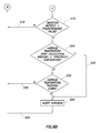
- the example method may then proceed to a determination as to whether the variation metrics are less all than a predetermined value for each of the calculation windows (block 616 ). If the variation metrics are all above the predetermined value, the active electrode may still have sufficient useful life, and thus the example method retreats to the beginning (along path 618 ) to begin anew in the next calculation window. On the other hand, if the variation metrics are all below the predetermined value, such may indicative that the active electrode 202 of the wand 102 is approaching, has reached, or has exceeded its useful life, or fluid flow through the wand is either fully or at least partially blocked. In some example systems the determination regarding the variation metric alone may be sufficient, and thus the system may alert the surgeon (block 620 ) and the example method moves again to the beginning (along path 622 ) to begin anew in the next calculation window.
- the determination regarding useful life of the active electrode may be augmented by a temperature component.
- the example method proceeds to temperature aspects of the overall determination.
- a determination is made as to whether the average temperature for each calculation window of the predetermined measurement period is below a predetermined threshold temperature (block 624 ). If so, the example method proceeds along path 626 to alerting the surgeon (again block 620 ).
- the example method moves to a determination as to whether the average temperature of each calculation window, when considered as a group, is trending toward the predetermined threshold temperature (block 628 ). If not, the example method retreats to the beginning (along path 630 ) to begin anew in the next calculation window. If so, the method proceeds to alerting the surgeon (again block 620 ).
Abstract
Description
Claims (16)
Priority Applications (6)
| Application Number | Priority Date | Filing Date | Title |
|---|---|---|---|
| US14/339,621 US9597142B2 (en) | 2014-07-24 | 2014-07-24 | Method and system related to electrosurgical procedures |
| CN201580051917.7A CN107072704B (en) | 2014-07-24 | 2015-06-25 | Methods and systems relating to electrosurgery |
| EP15736358.1A EP3171801B1 (en) | 2014-07-24 | 2015-06-25 | Electrosurgical systems |
| PCT/US2015/037610 WO2016014206A1 (en) | 2014-07-24 | 2015-06-25 | Method and system related to electrosurgical procedures |
| US15/448,909 US10595923B2 (en) | 2014-07-24 | 2017-03-03 | Method and system related to electrosurgical procedures |
| US16/788,596 US20200179031A1 (en) | 2014-07-24 | 2020-02-12 | Method and system related to electrosurgical procedures |
Applications Claiming Priority (1)
| Application Number | Priority Date | Filing Date | Title |
|---|---|---|---|
| US14/339,621 US9597142B2 (en) | 2014-07-24 | 2014-07-24 | Method and system related to electrosurgical procedures |
Related Child Applications (1)
| Application Number | Title | Priority Date | Filing Date |
|---|---|---|---|
| US15/448,909 Division US10595923B2 (en) | 2014-07-24 | 2017-03-03 | Method and system related to electrosurgical procedures |
Publications (2)
| Publication Number | Publication Date |
|---|---|
| US20160022350A1 US20160022350A1 (en) | 2016-01-28 |
| US9597142B2 true US9597142B2 (en) | 2017-03-21 |
Family
ID=53540871
Family Applications (3)
| Application Number | Title | Priority Date | Filing Date |
|---|---|---|---|
| US14/339,621 Active 2035-02-11 US9597142B2 (en) | 2014-07-24 | 2014-07-24 | Method and system related to electrosurgical procedures |
| US15/448,909 Active 2036-02-25 US10595923B2 (en) | 2014-07-24 | 2017-03-03 | Method and system related to electrosurgical procedures |
| US16/788,596 Pending US20200179031A1 (en) | 2014-07-24 | 2020-02-12 | Method and system related to electrosurgical procedures |
Family Applications After (2)
| Application Number | Title | Priority Date | Filing Date |
|---|---|---|---|
| US15/448,909 Active 2036-02-25 US10595923B2 (en) | 2014-07-24 | 2017-03-03 | Method and system related to electrosurgical procedures |
| US16/788,596 Pending US20200179031A1 (en) | 2014-07-24 | 2020-02-12 | Method and system related to electrosurgical procedures |
Country Status (4)
| Country | Link |
|---|---|
| US (3) | US9597142B2 (en) |
| EP (1) | EP3171801B1 (en) |
| CN (1) | CN107072704B (en) |
| WO (1) | WO2016014206A1 (en) |
Cited By (1)
| Publication number | Priority date | Publication date | Assignee | Title |
|---|---|---|---|---|
| US11660460B2 (en) | 2015-10-16 | 2023-05-30 | Stryker Corporation | Integrated pump control for dynamic control of plasma field |
Families Citing this family (5)
| Publication number | Priority date | Publication date | Assignee | Title |
|---|---|---|---|---|
| US9526556B2 (en) * | 2014-02-28 | 2016-12-27 | Arthrocare Corporation | Systems and methods systems related to electrosurgical wands with screen electrodes |
| GB201708081D0 (en) * | 2017-05-19 | 2017-07-05 | Alesi Surgical Ltd | Surgical assembly and system |
| CN109512503B (en) * | 2017-09-18 | 2020-03-31 | 四川锦江电子科技有限公司 | Low-temperature plasma ablation system capable of outputting stimulation |
| WO2019071269A2 (en) | 2017-10-06 | 2019-04-11 | Powell Charles Lee | System and method to treat obstructive sleep apnea |
| CN111938803B (en) * | 2020-08-20 | 2024-01-12 | 上海方润医疗科技股份有限公司 | Low-temperature plasma ablation power control device and system |
Citations (266)
| Publication number | Priority date | Publication date | Assignee | Title |
|---|---|---|---|---|
| US2050904A (en) | 1934-11-26 | 1936-08-11 | Trice Spencer Talley | Electric hemostat or cautery |
| US2275167A (en) | 1939-04-26 | 1942-03-03 | Bierman William | Electrosurgical instrument |
| US3699967A (en) | 1971-04-30 | 1972-10-24 | Valleylab Inc | Electrosurgical generator |
| US3812858A (en) | 1972-10-24 | 1974-05-28 | Sybron Corp | Dental electrosurgical unit |
| US3945375A (en) | 1972-04-04 | 1976-03-23 | Surgical Design Corporation | Rotatable surgical instrument |
| US4033351A (en) | 1974-06-14 | 1977-07-05 | Siemens Aktiengesellschaft | Bipolar cutting electrode for high-frequency surgery |
| US4203444A (en) | 1977-11-07 | 1980-05-20 | Dyonics, Inc. | Surgical instrument suitable for closed surgery such as of the knee |
| GB2037167A (en) | 1978-11-16 | 1980-07-09 | Corning Glass Works | Electrosurgical cutting instrument |
| US4240441A (en) | 1978-10-10 | 1980-12-23 | The United States Of America As Represented By The Secretary Of The Navy | Carotid thermodilution catheter |
| US4269174A (en) | 1979-08-06 | 1981-05-26 | Medical Dynamics, Inc. | Transcutaneous vasectomy apparatus and method |
| JPS57183850U (en) | 1981-05-15 | 1982-11-22 | ||
| US4411266A (en) | 1980-09-24 | 1983-10-25 | Cosman Eric R | Thermocouple radio frequency lesion electrode |
| US4429694A (en) | 1981-07-06 | 1984-02-07 | C. R. Bard, Inc. | Electrosurgical generator |
| US4483338A (en) | 1981-06-12 | 1984-11-20 | Raychem Corporation | Bi-Polar electrocautery needle |
| DE2521719C2 (en) | 1975-05-15 | 1985-06-20 | Delma, Elektro- Und Medizinische Apparatebaugesellschaft Mbh, 7200 Tuttlingen | Electrosurgical device |
| US4582057A (en) | 1981-07-20 | 1986-04-15 | Regents Of The University Of Washington | Fast pulse thermal cautery probe |
| US4641649A (en) | 1985-10-30 | 1987-02-10 | Rca Corporation | Method and apparatus for high frequency catheter ablation |
| US4674499A (en) | 1980-12-08 | 1987-06-23 | Pao David S C | Coaxial bipolar probe |
| US4709698A (en) | 1986-05-14 | 1987-12-01 | Thomas J. Fogarty | Heatable dilation catheter |
| US4719914A (en) | 1986-12-24 | 1988-01-19 | Johnson Gerald W | Electrosurgical instrument |
| US4737678A (en) | 1985-08-06 | 1988-04-12 | Pioneer Electronic Corporation | Cooling system for projection television receiver |
| US4736743A (en) | 1986-05-12 | 1988-04-12 | Surgical Laser Technology, Inc. | Vaporization contact laser probe |
| US4762128A (en) | 1986-12-09 | 1988-08-09 | Advanced Surgical Intervention, Inc. | Method and apparatus for treating hypertrophy of the prostate gland |
| JPS6340099Y2 (en) | 1980-05-16 | 1988-10-20 | ||
| US4785806A (en) | 1987-01-08 | 1988-11-22 | Yale University | Laser ablation process and apparatus |
| US4813429A (en) | 1986-05-12 | 1989-03-21 | Biodan Medical Systems Ltd. | Catheter and probe |
| US4827911A (en) | 1986-04-02 | 1989-05-09 | Cooper Lasersonics, Inc. | Method and apparatus for ultrasonic surgical fragmentation and removal of tissue |
| US4860752A (en) | 1988-02-18 | 1989-08-29 | Bsd Medical Corporation | Invasive microwave array with destructive and coherent phase |
| US4903696A (en) | 1988-10-06 | 1990-02-27 | Everest Medical Corporation | Electrosurgical generator |
| US4940064A (en) | 1986-11-14 | 1990-07-10 | Desai Jawahar M | Catheter for mapping and ablation and method therefor |
| US4955377A (en) | 1988-10-28 | 1990-09-11 | Lennox Charles D | Device and method for heating tissue in a patient's body |
| US4968314A (en) | 1987-10-07 | 1990-11-06 | University College | Surgical apparatus |
| US4976709A (en) | 1988-12-15 | 1990-12-11 | Sand Bruce J | Method for collagen treatment |
| US5007437A (en) | 1989-06-16 | 1991-04-16 | Mmtc, Inc. | Catheters for treating prostate disease |
| US5037421A (en) | 1989-10-06 | 1991-08-06 | Coherent, Inc., Medical Group | Mid-infrared laser arthroscopic procedure |
| WO1991013650A1 (en) | 1988-11-21 | 1991-09-19 | Technomed International | Method and apparatus for the surgical treatment of tissues by thermal effect and in particular the prostate, using a urethral microwave-emitting probe means |
| US5057106A (en) | 1986-02-27 | 1991-10-15 | Kasevich Associates, Inc. | Microwave balloon angioplasty |
| US5057105A (en) | 1989-08-28 | 1991-10-15 | The University Of Kansas Med Center | Hot tip catheter assembly |
| US5061266A (en) | 1988-03-30 | 1991-10-29 | Hakky Said I | Laser resectoscope and method |
| US5083565A (en) | 1990-08-03 | 1992-01-28 | Everest Medical Corporation | Electrosurgical instrument for ablating endocardial tissue |
| US5084045A (en) | 1990-09-17 | 1992-01-28 | Helenowski Tomasz K | Suction surgical instrument |
| US5092339A (en) | 1990-07-23 | 1992-03-03 | Geddes Leslie A | Method and apparatus for electrically compensated measurement of cardiac output |
| US5093877A (en) | 1990-10-30 | 1992-03-03 | Advanced Cardiovascular Systems | Optical fiber lasing apparatus lens |
| US5103804A (en) | 1990-07-03 | 1992-04-14 | Boston Scientific Corporation | Expandable tip hemostatic probes and the like |
| US5137530A (en) | 1985-09-27 | 1992-08-11 | Sand Bruce J | Collagen treatment apparatus |
| EP0502268A1 (en) | 1989-09-29 | 1992-09-09 | Everest Medical Corporation | Electrosurgical instrument having needle cutting electrode and spot-coagulation electrode |
| US5147354A (en) | 1988-08-19 | 1992-09-15 | Coherent, Inc. | Mid-infrared laser endoscope |
| US5151098A (en) | 1990-07-23 | 1992-09-29 | Hanspeter Loertscher | Apparatus for controlled tissue ablation |
| US5176528A (en) | 1992-06-11 | 1993-01-05 | Molex Incorporated | Pin and socket electrical connnector assembly |
| US5191883A (en) | 1988-10-28 | 1993-03-09 | Prutech Research And Development Partnership Ii | Device for heating tissue in a patient's body |
| US5217455A (en) | 1991-08-12 | 1993-06-08 | Tan Oon T | Laser treatment method for removing pigmentations, lesions, and abnormalities from the skin of a living human |
| US5230334A (en) | 1992-01-22 | 1993-07-27 | Summit Technology, Inc. | Method and apparatus for generating localized hyperthermia |
| US5234428A (en) | 1991-06-11 | 1993-08-10 | Kaufman David I | Disposable electrocautery/cutting instrument with integral continuous smoke evacuation |
| US5246438A (en) | 1988-11-25 | 1993-09-21 | Sensor Electronics, Inc. | Method of radiofrequency ablation |
| US5249585A (en) | 1988-07-28 | 1993-10-05 | Bsd Medical Corporation | Urethral inserted applicator for prostate hyperthermia |
| US5269794A (en) | 1987-02-18 | 1993-12-14 | Linvatec Corporation | Cutting blade assembly for an arthroscopic surgical instrument drive system |
| US5277696A (en) | 1991-11-19 | 1994-01-11 | Delma Elektro- Und Medizinische Apparatebau Gesellschaft Mbh | Medical high frequency coagulation instrument |
| WO1994003134A1 (en) | 1992-08-03 | 1994-02-17 | Sunrise Technologies, Inc. | Method and apparatus for exposing a human eye to a controlled pattern of radiation spots |
| US5293868A (en) | 1992-06-30 | 1994-03-15 | American Cardiac Ablation Co., Inc. | Cardiac ablation catheter having resistive mapping electrodes |
| US5295956A (en) | 1992-10-09 | 1994-03-22 | Symbiosis Corporation | Endoscopic suction instrument having variable suction strength capabilities |
| US5300099A (en) | 1992-03-06 | 1994-04-05 | Urologix, Inc. | Gamma matched, helical dipole microwave antenna |
| US5301687A (en) | 1991-06-06 | 1994-04-12 | Trustees Of Dartmouth College | Microwave applicator for transurethral hyperthermia |
| US5304169A (en) | 1985-09-27 | 1994-04-19 | Laser Biotech, Inc. | Method for collagen shrinkage |
| US5304170A (en) | 1993-03-12 | 1994-04-19 | Green Howard A | Method of laser-induced tissue necrosis in carotenoid-containing skin structures |
| US5312395A (en) | 1990-03-14 | 1994-05-17 | Boston University | Method of treating pigmented lesions using pulsed irradiation |
| WO1994010924A1 (en) | 1992-11-13 | 1994-05-26 | American Cardiac Ablation Co., Inc. | Fluid cooled electrosurgical probe |
| US5318563A (en) | 1992-06-04 | 1994-06-07 | Valley Forge Scientific Corporation | Bipolar RF generator |
| US5322507A (en) | 1992-08-11 | 1994-06-21 | Myriadlase, Inc. | Endoscope for treatment of prostate |
| WO1994014383A1 (en) | 1992-12-22 | 1994-07-07 | Laser Engineering, Inc. | Handpiece for transmyocardial vascularization heart-synchronized pulsed laser system |
| US5330518A (en) | 1992-03-06 | 1994-07-19 | Urologix, Inc. | Method for treating interstitial tissue associated with microwave thermal therapy |
| US5334183A (en) | 1985-08-28 | 1994-08-02 | Valleylab, Inc. | Endoscopic electrosurgical apparatus |
| US5334193A (en) | 1992-11-13 | 1994-08-02 | American Cardiac Ablation Co., Inc. | Fluid cooled ablation catheter |
| US5336220A (en) | 1992-10-09 | 1994-08-09 | Symbiosis Corporation | Tubing for endoscopic electrosurgical suction-irrigation instrument |
| US5335668A (en) | 1993-04-30 | 1994-08-09 | Medical Scientific, Inc. | Diagnostic impedance measuring system for an insufflation needle |
| US5336217A (en) | 1986-04-24 | 1994-08-09 | Institut National De La Sante Et De La Recherche Medicale (Insepm) | Process for treatment by irradiating an area of a body, and treatment apparatus usable in dermatology for the treatment of cutaneous angio dysplasias |
| US5348554A (en) | 1992-12-01 | 1994-09-20 | Cardiac Pathways Corporation | Catheter for RF ablation with cooled electrode |
| WO1994026228A1 (en) | 1993-05-10 | 1994-11-24 | Thapliyal And Eggers Partners | Methods and apparatus for surgical cutting |
| US5370642A (en) | 1991-09-25 | 1994-12-06 | Keller; Gregory S. | Method of laser cosmetic surgery |
| WO1995005780A1 (en) | 1993-08-23 | 1995-03-02 | Hood Larry L | Modifications of visual acuity by thermal means |
| WO1995005781A1 (en) | 1993-08-27 | 1995-03-02 | Medtronic, Inc. | Method and apparatus for r-f ablation |
| WO1995005867A1 (en) | 1993-08-27 | 1995-03-02 | Medtronic, Inc. | Apparatus for ablation |
| US5395363A (en) | 1993-06-29 | 1995-03-07 | Utah Medical Products | Diathermy coagulation and ablation apparatus and method |
| US5403311A (en) | 1993-03-29 | 1995-04-04 | Boston Scientific Corporation | Electro-coagulation and ablation and other electrotherapeutic treatments of body tissue |
| WO1995010326A1 (en) | 1993-10-14 | 1995-04-20 | Vesta Medical, Inc. | Bipolar/monopolar endometrial ablation device and method |
| US5423803A (en) | 1991-10-29 | 1995-06-13 | Thermotrex Corporation | Skin surface peeling process using laser |
| US5423844A (en) | 1993-10-22 | 1995-06-13 | Promex, Inc. | Rotary surgical cutting instrument |
| US5433708A (en) | 1991-05-17 | 1995-07-18 | Innerdyne, Inc. | Method and device for thermal ablation having improved heat transfer |
| US5437664A (en) | 1994-01-18 | 1995-08-01 | Endovascular, Inc. | Apparatus and method for venous ligation |
| US5458596A (en) | 1994-05-06 | 1995-10-17 | Dorsal Orthopedic Corporation | Method and apparatus for controlled contraction of soft tissue |
| US5462545A (en) | 1994-01-31 | 1995-10-31 | New England Medical Center Hospitals, Inc. | Catheter electrodes |
| US5484435A (en) | 1992-01-15 | 1996-01-16 | Conmed Corporation | Bipolar electrosurgical instrument for use in minimally invasive internal surgical procedures |
| US5487385A (en) | 1993-12-03 | 1996-01-30 | Avitall; Boaz | Atrial mapping and ablation catheter system |
| US5490850A (en) | 1993-05-20 | 1996-02-13 | Ellman; Alan G. | Graft harvesting hair transplants with electrosurgery |
| WO1996007360A1 (en) | 1994-09-08 | 1996-03-14 | Medtronic, Inc. | Mapping r- f ablating liquid injecting screw- in catheter mounted electrode |
| US5505710A (en) | 1994-08-22 | 1996-04-09 | C. R. Bard, Inc. | Telescoping probe |
| US5520685A (en) | 1994-08-04 | 1996-05-28 | Alto Development Corporation | Thermally-insulated anti-clog tip for electrocautery suction tubes |
| US5536267A (en) | 1993-11-08 | 1996-07-16 | Zomed International | Multiple electrode ablation apparatus |
| US5542928A (en) | 1991-05-17 | 1996-08-06 | Innerdyne, Inc. | Method and device for thermal ablation having improved heat transfer |
| US5545161A (en) | 1992-12-01 | 1996-08-13 | Cardiac Pathways Corporation | Catheter for RF ablation having cooled electrode with electrically insulated sleeve |
| DE29609350U1 (en) | 1996-05-24 | 1996-08-29 | P Osypka Mbh Ges Fuer Medizint | Device for perforating the heart wall |
| US5562703A (en) | 1994-06-14 | 1996-10-08 | Desai; Ashvin H. | Endoscopic surgical instrument |
| EP0597463A3 (en) | 1992-11-13 | 1996-11-06 | Dornier Med Systems Inc | Thermotherapiesonde. |
| WO1996034568A1 (en) | 1995-05-05 | 1996-11-07 | Knowlton Edward W | Apparatus for skin resurfacing |
| WO1996035469A1 (en) | 1995-05-10 | 1996-11-14 | Cardiogenesis Corporation | System for treating or diagnosing heart tissue |
| US5579764A (en) | 1993-01-08 | 1996-12-03 | Goldreyer; Bruce N. | Method and apparatus for spatially specific electrophysiological sensing in a catheter with an enlarged ablating electrode |
| WO1996039965A1 (en) | 1995-06-07 | 1996-12-19 | Cardiogenesis Corporation | Surgical channel forming device with penetration limiter |
| WO1996039964A1 (en) | 1995-06-07 | 1996-12-19 | Cardiogenesis Corporation | Probe for myocardial channel formation |
| WO1996039967A1 (en) | 1995-06-07 | 1996-12-19 | Ep Technologies, Inc. | Tissue heating and ablation systems and methods which predict maximum tissue temperature |
| WO1996039962A1 (en) | 1995-06-07 | 1996-12-19 | Cardiogenesis Corporation | Optical probe for myocardial channel formation |
| WO1996039914A1 (en) | 1995-06-07 | 1996-12-19 | Arthrocare Corporation | System and method for electrosurgical cutting and ablation |
| DE4425015C2 (en) | 1994-07-15 | 1997-01-16 | Winter & Ibe Olympus | Endoscopic electrosurgical device |
| US5607421A (en) | 1991-05-01 | 1997-03-04 | The Trustees Of Columbia University In The City Of New York | Myocardial revascularization through the endocardial surface using a laser |
| US5607391A (en) | 1991-10-18 | 1997-03-04 | United States Surgical Corporation | Endoscopic surgical instrument for aspiration and irrigation |
| DE19537084A1 (en) | 1995-10-05 | 1997-04-10 | Sievers Hans Hinrich Prof Dr M | Catheter for transmyocardial revasculation with guidable multi=ID main catheter |
| DE29619029U1 (en) | 1996-11-02 | 1997-04-10 | Kletke Georg Dr Med | Miocard puncture needle |
| WO1997015238A1 (en) | 1995-10-24 | 1997-05-01 | Oratec Interventions, Inc. | Rf method and apparatus for controlled depth ablation of soft tissue, such as collagen |
| US5626576A (en) | 1989-01-06 | 1997-05-06 | Advanced Coronary Intervention, Inc. | Electrosurgical catheter for resolving atherosclerotic plaque by radio frequency sparking |
| WO1997018765A1 (en) | 1995-11-22 | 1997-05-29 | Arthrocare Corporation | System and method for electrosurgical cutting and ablation |
| US5643255A (en) | 1994-12-12 | 1997-07-01 | Hicor, Inc. | Steerable catheter with rotatable tip electrode and method of use |
| WO1997024992A1 (en) | 1996-01-05 | 1997-07-17 | Knowlton Edward W | Method for scar collagen formation and contraction |
| WO1997025101A2 (en) | 1996-01-08 | 1997-07-17 | Biosense Inc. | Methods and apparatus for myocardial revascularization |
| US5653692A (en) | 1995-09-07 | 1997-08-05 | Innerdyne Medical, Inc. | Method and system for direct heating of fluid solution in a hollow body organ |
| WO1997032551A1 (en) | 1996-03-04 | 1997-09-12 | Energy Life Systems Corporation | Device and method for trans myocardial revascularization |
| WO1997033523A1 (en) | 1996-03-11 | 1997-09-18 | Medical Scientific, Inc. | Electrosurgical rotating cutting device |
| WO1997034540A1 (en) | 1996-03-22 | 1997-09-25 | Plc Medical Systems, Inc. | Video assisted thoracoscopic transmyocardial revascularization surgical method |
| US5681308A (en) | 1994-06-24 | 1997-10-28 | Stuart D. Edwards | Ablation apparatus for cardiac chambers |
| US5688267A (en) | 1995-05-01 | 1997-11-18 | Ep Technologies, Inc. | Systems and methods for sensing multiple temperature conditions during tissue ablation |
| WO1997044071A1 (en) | 1996-05-21 | 1997-11-27 | Amnon Sudai | Apparatus and methods for revascularization and perfusion |
| WO1997041786A3 (en) | 1996-05-06 | 1997-12-11 | Somnus Medical Tech Inc | Uvula, tonsil, adenoid and sinus tissue treatment device and method |
| US5713896A (en) | 1991-11-01 | 1998-02-03 | Medical Scientific, Inc. | Impedance feedback electrosurgical system |
| WO1998014131A1 (en) | 1996-10-02 | 1998-04-09 | Medtronic, Inc. | Fluid-assisted electrocautery device |
| US5743903A (en) | 1991-11-08 | 1998-04-28 | Ep Technologies, Inc. | Cardiac ablation systems and methods using tissue temperature monitoring and control |
| US5743870A (en) | 1994-05-09 | 1998-04-28 | Somnus Medical Technologies, Inc. | Ablation apparatus and system for removal of soft palate tissue |
| WO1998017185A1 (en) | 1996-10-24 | 1998-04-30 | Plc Medical Systems, Inc. | Gauging system for monitoring channel depth in percutaneous endocardial revascularization |
| WO1998017186A1 (en) | 1996-10-21 | 1998-04-30 | Plc Medical Systems, Inc. | Percutaneous transmyocardial revascularization marking system |
| US5746746A (en) | 1996-08-30 | 1998-05-05 | Garito; Jon C. | Electrosurgical electrode and method for skin resurfacing |
| US5749869A (en) | 1991-08-12 | 1998-05-12 | Karl Storz Gmbh & Co. | High-frequency surgical generator for cutting tissue |
| US5755753A (en) | 1995-05-05 | 1998-05-26 | Thermage, Inc. | Method for controlled contraction of collagen tissue |
| US5769843A (en) | 1996-02-20 | 1998-06-23 | Cormedica | Percutaneous endomyocardial revascularization |
| US5769847A (en) | 1994-06-27 | 1998-06-23 | Ep Technologies, Inc. | Systems and methods for controlling tissue ablation using multiple temperature sensing elements |
| WO1998027877A1 (en) | 1996-12-23 | 1998-07-02 | Advanced Coronary Intervention | Radio frequency transmyocardial revascularization |
| WO1998030144A1 (en) | 1997-01-08 | 1998-07-16 | Biosense Inc. | Monitoring of myocardial revascularization |
| US5782795A (en) | 1995-06-30 | 1998-07-21 | Xomed Surgical Products, Inc. | Surgical suction cutting instrument with internal irrigation |
| WO1998034550A1 (en) | 1997-02-10 | 1998-08-13 | West Hugh S Jr | Mechanical and electrical endoscopic surgical instrument |
| US5800431A (en) | 1996-10-11 | 1998-09-01 | Brown; Robert H. | Electrosurgical tool with suction and cautery |
| US5800429A (en) | 1994-06-24 | 1998-09-01 | Somnus Medical Technologies, Inc. | Noninvasive apparatus for ablating turbinates |
| WO1998038925A1 (en) | 1997-03-06 | 1998-09-11 | Scimed Life Systems, Inc. | Radiofrequency transmyocardial revascularization apparatus and method |
| WO1998039038A1 (en) | 1997-03-06 | 1998-09-11 | Scimed Life Systems, Inc. | Transmyocardial revascularization catheter and method |
| US5807384A (en) | 1996-12-20 | 1998-09-15 | Eclipse Surgical Technologies, Inc. | Transmyocardial revascularization (TMR) enhanced treatment for coronary artery disease |
| US5810802A (en) | 1994-08-08 | 1998-09-22 | E.P. Technologies, Inc. | Systems and methods for controlling tissue ablation using multiple temperature sensing elements |
| WO1998034558A3 (en) | 1997-02-12 | 1998-10-29 | Oratec Interventions Inc | Concave probe for arthroscopic surgery |
| US5843078A (en) | 1997-07-01 | 1998-12-01 | Sharkey; Hugh R. | Radio frequency device for resurfacing skin and method |
| US5855277A (en) | 1994-02-03 | 1999-01-05 | Rehrig Pacific Company, Inc. | Nestable display crate for bottles with handle feature |
| WO1999000060A1 (en) | 1997-06-26 | 1999-01-07 | Advanced Coronary Intervention | Electrosurgical catheter for resolving obstructions by radio frequency ablation |
| US5876398A (en) | 1994-09-08 | 1999-03-02 | Medtronic, Inc. | Method and apparatus for R-F ablation |
| EP0650701B1 (en) | 1993-11-01 | 1999-03-24 | Gyrus Medical Limited | Electrosurgical apparatus for laporoscopy and similar interventions |
| US5895386A (en) | 1996-12-20 | 1999-04-20 | Electroscope, Inc. | Bipolar coagulation apparatus and method for arthroscopy |
| WO1999020185A1 (en) | 1997-10-23 | 1999-04-29 | Arthrocare Corporation | Systems and methods for tissue resection, ablation and aspiration |
| DE19850671A1 (en) | 1997-11-06 | 1999-05-20 | Siemens Elema Ab | Ablation catheter for removal of damaged tissue |
| EP0923907A1 (en) | 1997-12-19 | 1999-06-23 | Gyrus Medical Limited | An electrosurgical instrument |
| WO1999042037A1 (en) | 1998-02-20 | 1999-08-26 | Arthrocare Corporation | Systems and methods for electrosurgical spine surgery |
| WO1999044506A1 (en) | 1998-03-03 | 1999-09-10 | Senorx, Inc. | Breast biopsy system and method |
| US5964754A (en) | 1996-05-24 | 1999-10-12 | Sulzer Osypka Gmbh | Device for perforating the heart wall |
| US5976127A (en) | 1998-01-14 | 1999-11-02 | Lax; Ronald | Soft tissue fixation devices |
| US5980516A (en) | 1993-08-27 | 1999-11-09 | Medtronic, Inc. | Method and apparatus for R-F ablation |
| US5980545A (en) | 1996-05-13 | 1999-11-09 | United States Surgical Corporation | Coring device and method |
| US5984919A (en) | 1991-02-13 | 1999-11-16 | Applied Medical Resources Corporation | Surgical trocar |
| US6007570A (en) | 1996-08-13 | 1999-12-28 | Oratec Interventions, Inc. | Apparatus with functional element for performing function upon intervertebral discs |
| US6007533A (en) | 1997-09-19 | 1999-12-28 | Oratec Interventions, Inc. | Electrocauterizing tip for orthopedic shave devices |
| US6030383A (en) | 1996-05-21 | 2000-02-29 | Benderev; Theodore V. | Electrosurgical instrument and method of use |
| US6032674A (en) | 1992-01-07 | 2000-03-07 | Arthrocare Corporation | Systems and methods for myocardial revascularization |
| US6032673A (en) | 1994-10-13 | 2000-03-07 | Femrx, Inc. | Methods and devices for tissue removal |
| US6042580A (en) | 1998-05-05 | 2000-03-28 | Cardiac Pacemakers, Inc. | Electrode having composition-matched, common-lead thermocouple wire for providing multiple temperature-sensitive junctions |
| US6045532A (en) | 1998-02-20 | 2000-04-04 | Arthrocare Corporation | Systems and methods for electrosurgical treatment of tissue in the brain and spinal cord |
| US6053172A (en) | 1995-06-07 | 2000-04-25 | Arthrocare Corporation | Systems and methods for electrosurgical sinus surgery |
| US6063081A (en) | 1995-02-22 | 2000-05-16 | Medtronic, Inc. | Fluid-assisted electrocautery device |
| US6091995A (en) | 1996-11-08 | 2000-07-18 | Surx, Inc. | Devices, methods, and systems for shrinking tissues |
| US6096037A (en) | 1997-07-29 | 2000-08-01 | Medtronic, Inc. | Tissue sealing electrosurgery device and methods of sealing tissue |
| US6110169A (en) | 1996-02-07 | 2000-08-29 | Kari Desinger | Cutting device for electrotomy |
| US6152923A (en) | 1999-04-28 | 2000-11-28 | Sherwood Services Ag | Multi-contact forceps and method of sealing, coagulating, cauterizing and/or cutting vessels and tissue |
| US6156031A (en) | 1995-08-09 | 2000-12-05 | Eclipse Surgical Technologies | Transmyocardial revascularization using radiofrequency energy |
| US6210405B1 (en) | 1996-06-20 | 2001-04-03 | Gyrus Medical Limited | Under water treatment |
| US6214001B1 (en) | 1997-09-19 | 2001-04-10 | Oratec Interventions, Inc. | Electrocauterizing tool for orthopedic shave devices |
| US6217575B1 (en) | 1999-02-24 | 2001-04-17 | Scimed Life Systems, Inc. | PMR catheter |
| WO2001026570A1 (en) | 1999-10-13 | 2001-04-19 | Arthrocare Corporation | Systems and methods for treating spinal pain |
| US6235023B1 (en) | 1995-08-15 | 2001-05-22 | Rita Medical Systems, Inc. | Cell necrosis apparatus |
| US6238393B1 (en) | 1998-07-07 | 2001-05-29 | Medtronic, Inc. | Method and apparatus for creating a bi-polar virtual electrode used for the ablation of tissue |
| US6264650B1 (en) | 1995-06-07 | 2001-07-24 | Arthrocare Corporation | Methods for electrosurgical treatment of intervertebral discs |
| US6267757B1 (en) | 1995-08-09 | 2001-07-31 | Eclipse Surgical Technologies, Inc. | Revascularization with RF ablation |
| US6302903B1 (en) | 1998-07-07 | 2001-10-16 | Medtronic, Inc. | Straight needle apparatus for creating a virtual electrode used for the ablation of tissue |
| US6312429B1 (en) | 1998-09-01 | 2001-11-06 | Senorx, Inc. | Electrosurgical lesion location device |
| US6315774B1 (en) | 1996-03-29 | 2001-11-13 | Eclipse Surgical Technologies, Inc. | Minimally invasive apparatus for forming revascularization channels |
| US6322494B1 (en) | 1998-04-03 | 2001-11-27 | Gyrus Medical Limited | Endoscope |
| US6327505B1 (en) | 1998-05-07 | 2001-12-04 | Medtronic, Inc. | Method and apparatus for rf intraluminal reduction and occlusion |
| US6325799B1 (en) | 1997-04-24 | 2001-12-04 | Gyrus Medical Limited | Electrosurgical instrument |
| WO2001095819A1 (en) | 2000-06-09 | 2001-12-20 | Arthrocare Corporation | Electrosurgical apparatus and methods for ablating tissue |
| US6336926B1 (en) | 1999-01-15 | 2002-01-08 | Gyrus Medical Limited | Electrosurgical system |
| GB2331247B (en) | 1997-11-13 | 2002-01-09 | John Hugh Davey Walton | Improvements in relation to apparatus for surgical diathermy |
| US6346107B1 (en) | 1990-12-14 | 2002-02-12 | Robert L. Cucin | Power-assisted liposuction instrument with cauterizing cannual assembly |
| US6355006B1 (en) | 1997-02-06 | 2002-03-12 | Exogen, Inc. | Method and apparatus for cartilage growth stimulation |
| US6358248B1 (en) | 1995-02-22 | 2002-03-19 | Medtronic, Inc. | Ball point fluid-assisted electrocautery device |
| US20020049438A1 (en) | 1999-10-05 | 2002-04-25 | Oratec Interventions, Inc. | Surgical instrument having distal face with first and second electrodes |
| US6398781B1 (en) | 1999-03-05 | 2002-06-04 | Gyrus Medical Limited | Electrosurgery system |
| US20020072739A1 (en) | 2000-12-07 | 2002-06-13 | Roberta Lee | Methods and devices for radiofrequency electrosurgery |
| US6409724B1 (en) | 1999-05-28 | 2002-06-25 | Gyrus Medical Limited | Electrosurgical instrument |
| US6432105B1 (en) | 2000-12-04 | 2002-08-13 | Alan G. Ellman | Bipolar electrosurgical handpiece for treating tissue |
| WO2000009053A9 (en) | 1998-08-11 | 2002-08-22 | Arthrocare Corp | Systems and methods for electrosurgical tissue treatment in the presence of electrically conductive fluid |
| WO2002078557A1 (en) | 2001-03-30 | 2002-10-10 | Ethicon Endo-Surgery, Inc. | Endoscopic ablation system with improved electrode geometry |
| US6491690B1 (en) | 1997-07-18 | 2002-12-10 | Gyrus Medical Limited | Electrosurgical instrument |
| US6497706B1 (en) | 1998-03-03 | 2002-12-24 | Senorx, Inc. | Biopsy device and method of use |
| US6497705B2 (en) | 1998-07-07 | 2002-12-24 | Medtronic, Inc. | Method and apparatus for creating a virtual electrode used for the ablation of tissue |
| US6510854B2 (en) | 2000-03-16 | 2003-01-28 | Gyrus Medical Limited | Method of treatment of prostatic adenoma |
| US6514250B1 (en) | 2000-04-27 | 2003-02-04 | Medtronic, Inc. | Suction stabilized epicardial ablation devices |
| US20030036753A1 (en) | 2001-08-15 | 2003-02-20 | Morgan Roy E. | Methods and devices for electrosurgery |
| WO2003024339A1 (en) | 2001-09-21 | 2003-03-27 | Gyrus Medical Limited | Surgical system and method for cutting and coagulation |
| US6557559B1 (en) | 1992-01-07 | 2003-05-06 | Arthrocare Corporation | Electrosurgical systems and methods with temperature control |
| US20030097129A1 (en) | 1998-01-21 | 2003-05-22 | Arthrocare Corporation | Apparatus and methods for electrosurgical removal and digestion of tissue |
| US6575969B1 (en) | 1995-05-04 | 2003-06-10 | Sherwood Services Ag | Cool-tip radiofrequency thermosurgery electrode system for tumor ablation |
| US6575968B1 (en) | 1992-01-07 | 2003-06-10 | Arthrocare Corp. | Electrosurgical system for treating the spine |
| US6582423B1 (en) | 1997-06-13 | 2003-06-24 | Arthrocare Corporation | Electrosurgical systems and methods for recanalization of occluded body lumens |
| US20030130711A1 (en) | 2001-09-28 | 2003-07-10 | Pearson Robert M. | Impedance controlled tissue ablation apparatus and method |
| US6597950B2 (en) | 1999-01-25 | 2003-07-22 | Cardiac Pacemakers, Inc. | Cardiac rhythm management system with painless defibrillation lead impedance measurement |
| US6595990B1 (en) | 1992-01-07 | 2003-07-22 | Arthrocare Corporation | Systems and methods for electrosurgical tissue revascularization |
| US6605085B1 (en) | 1993-11-08 | 2003-08-12 | Rita Medical Systems, Inc. | RF treatment apparatus |
| US6610059B1 (en) | 2002-02-25 | 2003-08-26 | Hs West Investments Llc | Endoscopic instruments and methods for improved bubble aspiration at a surgical site |
| US6632230B2 (en) | 2001-04-12 | 2003-10-14 | Scimed Life Systems, Inc. | Ablation system with catheter clearing abrasive |
| US6645203B2 (en) | 1997-02-12 | 2003-11-11 | Oratec Interventions, Inc. | Surgical instrument with off-axis electrode |
| US6663628B2 (en) | 2000-09-24 | 2003-12-16 | Medtronic, Inc. | Surgical micro-resecting instrument with electrocautery feature |
| US20040030330A1 (en) | 2002-04-18 | 2004-02-12 | Brassell James L. | Electrosurgery systems |
| US6695839B2 (en) | 2001-02-08 | 2004-02-24 | Oratec Interventions, Inc. | Method and apparatus for treatment of disrupted articular cartilage |
| US6699244B2 (en) | 1997-02-12 | 2004-03-02 | Oratec Interventions, Inc. | Electrosurgical instrument having a chamber to volatize a liquid |
| US6702810B2 (en) | 2000-03-06 | 2004-03-09 | Tissuelink Medical Inc. | Fluid delivery system and controller for electrosurgical devices |
| EP1041933B1 (en) | 1997-11-25 | 2004-03-31 | ArthroCare Corporation | Systems for electrosurgical treatment of the skin |
| DE10254668A1 (en) | 2002-11-22 | 2004-06-09 | Großpointner, Martina | Device for the treatment of vascular defects |
| US6763836B2 (en) | 1998-06-02 | 2004-07-20 | Arthrocare Corporation | Methods for electrosurgical tendon vascularization |
| US6796982B2 (en) | 2001-06-05 | 2004-09-28 | Electrosurgery Associates, Llc | Instant ignition electrosurgical probe and method for electrosurgical cutting and ablation |
| US6805130B2 (en) | 1995-11-22 | 2004-10-19 | Arthrocare Corporation | Methods for electrosurgical tendon vascularization |
| US6827725B2 (en) | 2001-05-10 | 2004-12-07 | Gyrus Medical Limited | Surgical instrument |
| US6855143B2 (en) | 1997-06-13 | 2005-02-15 | Arthrocare Corporation | Electrosurgical systems and methods for recanalization of occluded body lumens |
| US6896674B1 (en) | 1993-05-10 | 2005-05-24 | Arthrocare Corporation | Electrosurgical apparatus having digestion electrode and methods related thereto |
| US6904303B2 (en) | 1999-11-22 | 2005-06-07 | Boston Scientific Scimed, Inc. | Apparatus for mapping and coagulating soft tissue in or around body orifices |
| US6979332B2 (en) | 2003-11-04 | 2005-12-27 | Medtronic, Inc. | Surgical micro-resecting instrument with electrocautery and continuous aspiration features |
| US7150747B1 (en) | 2003-01-22 | 2006-12-19 | Smith & Nephew, Inc. | Electrosurgical cutter |
| US20070149965A1 (en) | 2005-12-13 | 2007-06-28 | Arthrex, Inc. | Aspirating electrosurgical probe with aspiration through electrode face |
| GB2408936B (en) | 2003-12-09 | 2007-07-18 | Gyrus Group Plc | A surgical instrument |
| US7258690B2 (en) | 2003-03-28 | 2007-08-21 | Relievant Medsystems, Inc. | Windowed thermal ablation probe |
| US20080021447A1 (en) | 1998-08-11 | 2008-01-24 | Arthrocare Corporation | Instrument for electrosurgical tissue treatment |
| DE202008000276U1 (en) | 2007-01-05 | 2008-05-15 | ArthroCare Corp., Austin | Electrosurgical system with suction control instrument and system |
| WO2008073727A1 (en) | 2006-12-07 | 2008-06-19 | Terumo Kabushiki Kaisha | Apparatus and methods for multipolar tissue welding |
| US20080167646A1 (en) | 2004-05-26 | 2008-07-10 | Baylis Medical Company Inc. | Electrosurgical apparatus having a temperature sensor |
| US20080234673A1 (en) | 2007-03-20 | 2008-09-25 | Arthrocare Corporation | Multi-electrode instruments |
| US7429262B2 (en) | 1992-01-07 | 2008-09-30 | Arthrocare Corporation | Apparatus and methods for electrosurgical ablation and resection of target tissue |
| US7488295B2 (en) | 1998-04-08 | 2009-02-10 | Senorx, Inc. | Tissue acquisition system and method of use |
| US20090138011A1 (en) | 2007-03-13 | 2009-05-28 | Gordon Epstein | Intermittent ablation rf driving for moderating return electrode temperature |
| WO2009094392A2 (en) | 2008-01-21 | 2009-07-30 | Halt Medical Inc. | Intermittent ablation rf driving for moderating return electrode temperature |
| US20090209958A1 (en) | 2006-01-06 | 2009-08-20 | Arthrocare Corporation | Electrosurgical system and method for treating chronic wound tissue |
| US20100042095A1 (en) | 2008-08-13 | 2010-02-18 | Robert Bigley | Systems and methods for screen electrode securement |
| DE102009057921A1 (en) | 2008-12-12 | 2010-06-24 | ArthroCare Corp., Austin | Systems and methods for limiting joint temperature |
| US20100204690A1 (en) | 2008-08-13 | 2010-08-12 | Arthrocare Corporation | Single aperture electrode assembly |
| US7776034B2 (en) | 2005-06-15 | 2010-08-17 | St. Jude Medical, Atrial Fibrillation Division, Inc. | Ablation catheter with adjustable virtual electrode |
| WO2011071482A1 (en) | 2009-12-07 | 2011-06-16 | Arthrocare Corporation | Single aperture electrode assembly |
| US8038670B2 (en) | 2000-03-06 | 2011-10-18 | Salient Surgical Technologies, Inc. | Fluid-assisted medical devices, systems and methods |
| US20110270242A1 (en) | 2010-04-30 | 2011-11-03 | Marion Duane W | Electrosurgical system and method having enhanced temperature measurement |
| US20120179157A1 (en) | 2011-01-06 | 2012-07-12 | Andrew Frazier | Systems and methods for screen electrode securement |
| US8317786B2 (en) | 2009-09-25 | 2012-11-27 | AthroCare Corporation | System, method and apparatus for electrosurgical instrument with movable suction sheath |
| US8323279B2 (en) | 2009-09-25 | 2012-12-04 | Arthocare Corporation | System, method and apparatus for electrosurgical instrument with movable fluid delivery sheath |
Family Cites Families (20)
| Publication number | Priority date | Publication date | Assignee | Title |
|---|---|---|---|---|
| JPH0641033B2 (en) * | 1985-11-29 | 1994-06-01 | 株式会社田中製作所 | Anomaly detection device for plasma torch electrodes, etc. |
| US6142992A (en) | 1993-05-10 | 2000-11-07 | Arthrocare Corporation | Power supply for limiting power in electrosurgery |
| US6355032B1 (en) | 1995-06-07 | 2002-03-12 | Arthrocare Corporation | Systems and methods for selective electrosurgical treatment of body structures |
| US6235020B1 (en) | 1993-05-10 | 2001-05-22 | Arthrocare Corporation | Power supply and methods for fluid delivery in electrosurgery |
| AUPM470994A0 (en) * | 1994-03-25 | 1994-04-21 | Commonwealth Scientific And Industrial Research Organisation | Plasma torch condition monitoring |
| US6149120A (en) | 1997-03-27 | 2000-11-21 | Hall; Donald M. | Low profile slidable shelf |
| US7255709B2 (en) * | 1998-04-21 | 2007-08-14 | Alsius Corporation | Intravascular heat exchange catheter with temperature sensor |
| FR2780953B1 (en) | 1998-07-09 | 2000-09-29 | Itw De France | SHUTTER FOR AN OPENING MADE IN A SHEET |
| CN100346869C (en) * | 2001-02-07 | 2007-11-07 | 尼弗茹斯公司 | Method and apparatus for hemodiafiltration delivery module |
| US20050267466A1 (en) * | 2004-05-26 | 2005-12-01 | Staunton Douglas A | Thermocouple electrode |
| EP1977173A4 (en) * | 2006-01-19 | 2012-06-27 | Keith Michael Rosiello | Method and system for warming or cooling a fluid |
| US8652086B2 (en) * | 2006-09-08 | 2014-02-18 | Abbott Medical Optics Inc. | Systems and methods for power and flow rate control |
| AT503646B1 (en) * | 2006-09-15 | 2007-12-15 | Fronius Int Gmbh | Water vapor plasma burner for cutting a workpiece, comprises a feed line for a liquid, a heating device, an evaporator for forming a gas from the liquid, a cathode detachably connected to a movably mounted piston rod, and a nozzle |
| US8147443B2 (en) * | 2007-12-28 | 2012-04-03 | Boston Scientific Scimed, Inc. | Indirect fluid flow measurement |
| US20090318914A1 (en) * | 2008-06-18 | 2009-12-24 | Utley David S | System and method for ablational treatment of uterine cervical neoplasia |
| US8066704B2 (en) * | 2008-06-20 | 2011-11-29 | Linvatec Corporation | Suction ablator |
| US8257350B2 (en) | 2009-06-17 | 2012-09-04 | Arthrocare Corporation | Method and system of an electrosurgical controller with wave-shaping |
| US9204918B2 (en) * | 2011-09-28 | 2015-12-08 | RELIGN Corporation | Medical ablation system and method of use |
| CN106823131B (en) * | 2011-09-30 | 2019-12-20 | 柯惠有限合伙公司 | Energy transfer device and method of use |
| US9713489B2 (en) * | 2013-03-07 | 2017-07-25 | Arthrocare Corporation | Electrosurgical methods and systems |
-
2014
- 2014-07-24 US US14/339,621 patent/US9597142B2/en active Active
-
2015
- 2015-06-25 CN CN201580051917.7A patent/CN107072704B/en active Active
- 2015-06-25 WO PCT/US2015/037610 patent/WO2016014206A1/en active Application Filing
- 2015-06-25 EP EP15736358.1A patent/EP3171801B1/en active Active
-
2017
- 2017-03-03 US US15/448,909 patent/US10595923B2/en active Active
-
2020
- 2020-02-12 US US16/788,596 patent/US20200179031A1/en active Pending
Patent Citations (309)
| Publication number | Priority date | Publication date | Assignee | Title |
|---|---|---|---|---|
| US2050904A (en) | 1934-11-26 | 1936-08-11 | Trice Spencer Talley | Electric hemostat or cautery |
| US2275167A (en) | 1939-04-26 | 1942-03-03 | Bierman William | Electrosurgical instrument |
| US3699967A (en) | 1971-04-30 | 1972-10-24 | Valleylab Inc | Electrosurgical generator |
| US3945375A (en) | 1972-04-04 | 1976-03-23 | Surgical Design Corporation | Rotatable surgical instrument |
| US3812858A (en) | 1972-10-24 | 1974-05-28 | Sybron Corp | Dental electrosurgical unit |
| US4033351A (en) | 1974-06-14 | 1977-07-05 | Siemens Aktiengesellschaft | Bipolar cutting electrode for high-frequency surgery |
| DE2521719C2 (en) | 1975-05-15 | 1985-06-20 | Delma, Elektro- Und Medizinische Apparatebaugesellschaft Mbh, 7200 Tuttlingen | Electrosurgical device |
| US4203444A (en) | 1977-11-07 | 1980-05-20 | Dyonics, Inc. | Surgical instrument suitable for closed surgery such as of the knee |
| US4203444B1 (en) | 1977-11-07 | 1987-07-21 | ||
| US4240441A (en) | 1978-10-10 | 1980-12-23 | The United States Of America As Represented By The Secretary Of The Navy | Carotid thermodilution catheter |
| GB2037167A (en) | 1978-11-16 | 1980-07-09 | Corning Glass Works | Electrosurgical cutting instrument |
| US4269174A (en) | 1979-08-06 | 1981-05-26 | Medical Dynamics, Inc. | Transcutaneous vasectomy apparatus and method |
| JPS6340099Y2 (en) | 1980-05-16 | 1988-10-20 | ||
| US4411266A (en) | 1980-09-24 | 1983-10-25 | Cosman Eric R | Thermocouple radio frequency lesion electrode |
| US4674499A (en) | 1980-12-08 | 1987-06-23 | Pao David S C | Coaxial bipolar probe |
| JPS57183850U (en) | 1981-05-15 | 1982-11-22 | ||
| US4483338A (en) | 1981-06-12 | 1984-11-20 | Raychem Corporation | Bi-Polar electrocautery needle |
| US4429694A (en) | 1981-07-06 | 1984-02-07 | C. R. Bard, Inc. | Electrosurgical generator |
| US4582057A (en) | 1981-07-20 | 1986-04-15 | Regents Of The University Of Washington | Fast pulse thermal cautery probe |
| US4737678A (en) | 1985-08-06 | 1988-04-12 | Pioneer Electronic Corporation | Cooling system for projection television receiver |
| US5334183A (en) | 1985-08-28 | 1994-08-02 | Valleylab, Inc. | Endoscopic electrosurgical apparatus |
| US5137530A (en) | 1985-09-27 | 1992-08-11 | Sand Bruce J | Collagen treatment apparatus |
| US5304169A (en) | 1985-09-27 | 1994-04-19 | Laser Biotech, Inc. | Method for collagen shrinkage |
| US5374265A (en) | 1985-09-27 | 1994-12-20 | Laser Biotech, Inc. | Collagen treatment apparatus and method |
| US4641649A (en) | 1985-10-30 | 1987-02-10 | Rca Corporation | Method and apparatus for high frequency catheter ablation |
| US5057106A (en) | 1986-02-27 | 1991-10-15 | Kasevich Associates, Inc. | Microwave balloon angioplasty |
| US4827911A (en) | 1986-04-02 | 1989-05-09 | Cooper Lasersonics, Inc. | Method and apparatus for ultrasonic surgical fragmentation and removal of tissue |
| US5336217A (en) | 1986-04-24 | 1994-08-09 | Institut National De La Sante Et De La Recherche Medicale (Insepm) | Process for treatment by irradiating an area of a body, and treatment apparatus usable in dermatology for the treatment of cutaneous angio dysplasias |
| US4813429A (en) | 1986-05-12 | 1989-03-21 | Biodan Medical Systems Ltd. | Catheter and probe |
| US4736743A (en) | 1986-05-12 | 1988-04-12 | Surgical Laser Technology, Inc. | Vaporization contact laser probe |
| US4709698A (en) | 1986-05-14 | 1987-12-01 | Thomas J. Fogarty | Heatable dilation catheter |
| US4940064A (en) | 1986-11-14 | 1990-07-10 | Desai Jawahar M | Catheter for mapping and ablation and method therefor |
| US4762128A (en) | 1986-12-09 | 1988-08-09 | Advanced Surgical Intervention, Inc. | Method and apparatus for treating hypertrophy of the prostate gland |
| US4719914A (en) | 1986-12-24 | 1988-01-19 | Johnson Gerald W | Electrosurgical instrument |
| US4785806A (en) | 1987-01-08 | 1988-11-22 | Yale University | Laser ablation process and apparatus |
| US5269794A (en) | 1987-02-18 | 1993-12-14 | Linvatec Corporation | Cutting blade assembly for an arthroscopic surgical instrument drive system |
| US4968314A (en) | 1987-10-07 | 1990-11-06 | University College | Surgical apparatus |
| US4860752A (en) | 1988-02-18 | 1989-08-29 | Bsd Medical Corporation | Invasive microwave array with destructive and coherent phase |
| US5061266A (en) | 1988-03-30 | 1991-10-29 | Hakky Said I | Laser resectoscope and method |
| US5249585A (en) | 1988-07-28 | 1993-10-05 | Bsd Medical Corporation | Urethral inserted applicator for prostate hyperthermia |
| US5147354B1 (en) | 1988-08-19 | 1997-10-14 | Coherent Inc | Mid-infrared laser endoscope |
| US5147354A (en) | 1988-08-19 | 1992-09-15 | Coherent, Inc. | Mid-infrared laser endoscope |
| US4903696A (en) | 1988-10-06 | 1990-02-27 | Everest Medical Corporation | Electrosurgical generator |
| US4955377A (en) | 1988-10-28 | 1990-09-11 | Lennox Charles D | Device and method for heating tissue in a patient's body |
| US5191883A (en) | 1988-10-28 | 1993-03-09 | Prutech Research And Development Partnership Ii | Device for heating tissue in a patient's body |
| WO1991013650A1 (en) | 1988-11-21 | 1991-09-19 | Technomed International | Method and apparatus for the surgical treatment of tissues by thermal effect and in particular the prostate, using a urethral microwave-emitting probe means |
| US5246438A (en) | 1988-11-25 | 1993-09-21 | Sensor Electronics, Inc. | Method of radiofrequency ablation |
| US5370644A (en) | 1988-11-25 | 1994-12-06 | Sensor Electronics, Inc. | Radiofrequency ablation catheter |
| US4976709A (en) | 1988-12-15 | 1990-12-11 | Sand Bruce J | Method for collagen treatment |
| US5626576A (en) | 1989-01-06 | 1997-05-06 | Advanced Coronary Intervention, Inc. | Electrosurgical catheter for resolving atherosclerotic plaque by radio frequency sparking |
| US5007437A (en) | 1989-06-16 | 1991-04-16 | Mmtc, Inc. | Catheters for treating prostate disease |
| US5057105A (en) | 1989-08-28 | 1991-10-15 | The University Of Kansas Med Center | Hot tip catheter assembly |
| EP0502268A1 (en) | 1989-09-29 | 1992-09-09 | Everest Medical Corporation | Electrosurgical instrument having needle cutting electrode and spot-coagulation electrode |
| US5037421A (en) | 1989-10-06 | 1991-08-06 | Coherent, Inc., Medical Group | Mid-infrared laser arthroscopic procedure |
| US5312395A (en) | 1990-03-14 | 1994-05-17 | Boston University | Method of treating pigmented lesions using pulsed irradiation |
| US5103804A (en) | 1990-07-03 | 1992-04-14 | Boston Scientific Corporation | Expandable tip hemostatic probes and the like |
| US5151098A (en) | 1990-07-23 | 1992-09-29 | Hanspeter Loertscher | Apparatus for controlled tissue ablation |
| US5092339A (en) | 1990-07-23 | 1992-03-03 | Geddes Leslie A | Method and apparatus for electrically compensated measurement of cardiac output |
| US5083565A (en) | 1990-08-03 | 1992-01-28 | Everest Medical Corporation | Electrosurgical instrument for ablating endocardial tissue |
| US5084045A (en) | 1990-09-17 | 1992-01-28 | Helenowski Tomasz K | Suction surgical instrument |
| US5093877A (en) | 1990-10-30 | 1992-03-03 | Advanced Cardiovascular Systems | Optical fiber lasing apparatus lens |
| US6346107B1 (en) | 1990-12-14 | 2002-02-12 | Robert L. Cucin | Power-assisted liposuction instrument with cauterizing cannual assembly |
| US5984919A (en) | 1991-02-13 | 1999-11-16 | Applied Medical Resources Corporation | Surgical trocar |
| EP0515867B1 (en) | 1991-05-01 | 1999-07-07 | The Trustees Of Columbia University In The City Of New York | Myocardial revascularization through the endocardial surface using a laser |
| US5607421A (en) | 1991-05-01 | 1997-03-04 | The Trustees Of Columbia University In The City Of New York | Myocardial revascularization through the endocardial surface using a laser |
| US5542928A (en) | 1991-05-17 | 1996-08-06 | Innerdyne, Inc. | Method and device for thermal ablation having improved heat transfer |
| US5433708A (en) | 1991-05-17 | 1995-07-18 | Innerdyne, Inc. | Method and device for thermal ablation having improved heat transfer |
| US5301687A (en) | 1991-06-06 | 1994-04-12 | Trustees Of Dartmouth College | Microwave applicator for transurethral hyperthermia |
| US5234428A (en) | 1991-06-11 | 1993-08-10 | Kaufman David I | Disposable electrocautery/cutting instrument with integral continuous smoke evacuation |
| US5749869A (en) | 1991-08-12 | 1998-05-12 | Karl Storz Gmbh & Co. | High-frequency surgical generator for cutting tissue |
| US5217455A (en) | 1991-08-12 | 1993-06-08 | Tan Oon T | Laser treatment method for removing pigmentations, lesions, and abnormalities from the skin of a living human |
| US5445634A (en) | 1991-09-25 | 1995-08-29 | Keller; Gregory S. | Method of laser cosmetic surgery |
| US5370642A (en) | 1991-09-25 | 1994-12-06 | Keller; Gregory S. | Method of laser cosmetic surgery |
| US5607391A (en) | 1991-10-18 | 1997-03-04 | United States Surgical Corporation | Endoscopic surgical instrument for aspiration and irrigation |
| US5423803A (en) | 1991-10-29 | 1995-06-13 | Thermotrex Corporation | Skin surface peeling process using laser |
| US5713896A (en) | 1991-11-01 | 1998-02-03 | Medical Scientific, Inc. | Impedance feedback electrosurgical system |
| US5743903A (en) | 1991-11-08 | 1998-04-28 | Ep Technologies, Inc. | Cardiac ablation systems and methods using tissue temperature monitoring and control |
| EP0543123B1 (en) | 1991-11-19 | 1996-03-20 | DELMA ELEKTRO-UND MEDIZINISCHE APPARATEBAU GESELLSCHAFT mbH | Medical high frequency coagulation device |
| US5277696A (en) | 1991-11-19 | 1994-01-11 | Delma Elektro- Und Medizinische Apparatebau Gesellschaft Mbh | Medical high frequency coagulation instrument |
| US6575968B1 (en) | 1992-01-07 | 2003-06-10 | Arthrocare Corp. | Electrosurgical system for treating the spine |
| US7429262B2 (en) | 1992-01-07 | 2008-09-30 | Arthrocare Corporation | Apparatus and methods for electrosurgical ablation and resection of target tissue |
| US7819863B2 (en) | 1992-01-07 | 2010-10-26 | Arthrocare Corporation | System and method for electrosurgical cutting and ablation |
| US6595990B1 (en) | 1992-01-07 | 2003-07-22 | Arthrocare Corporation | Systems and methods for electrosurgical tissue revascularization |
| US6032674A (en) | 1992-01-07 | 2000-03-07 | Arthrocare Corporation | Systems and methods for myocardial revascularization |
| US6557559B1 (en) | 1992-01-07 | 2003-05-06 | Arthrocare Corporation | Electrosurgical systems and methods with temperature control |
| US5484435A (en) | 1992-01-15 | 1996-01-16 | Conmed Corporation | Bipolar electrosurgical instrument for use in minimally invasive internal surgical procedures |
| US5230334A (en) | 1992-01-22 | 1993-07-27 | Summit Technology, Inc. | Method and apparatus for generating localized hyperthermia |
| US5300099A (en) | 1992-03-06 | 1994-04-05 | Urologix, Inc. | Gamma matched, helical dipole microwave antenna |
| US5330518A (en) | 1992-03-06 | 1994-07-19 | Urologix, Inc. | Method for treating interstitial tissue associated with microwave thermal therapy |
| US5318563A (en) | 1992-06-04 | 1994-06-07 | Valley Forge Scientific Corporation | Bipolar RF generator |
| US5176528A (en) | 1992-06-11 | 1993-01-05 | Molex Incorporated | Pin and socket electrical connnector assembly |
| US5293868A (en) | 1992-06-30 | 1994-03-15 | American Cardiac Ablation Co., Inc. | Cardiac ablation catheter having resistive mapping electrodes |
| WO1994003134A1 (en) | 1992-08-03 | 1994-02-17 | Sunrise Technologies, Inc. | Method and apparatus for exposing a human eye to a controlled pattern of radiation spots |
| US5322507A (en) | 1992-08-11 | 1994-06-21 | Myriadlase, Inc. | Endoscope for treatment of prostate |
| US5295956A (en) | 1992-10-09 | 1994-03-22 | Symbiosis Corporation | Endoscopic suction instrument having variable suction strength capabilities |
| US5336220A (en) | 1992-10-09 | 1994-08-09 | Symbiosis Corporation | Tubing for endoscopic electrosurgical suction-irrigation instrument |
| US5334193A (en) | 1992-11-13 | 1994-08-02 | American Cardiac Ablation Co., Inc. | Fluid cooled ablation catheter |
| EP0597463A3 (en) | 1992-11-13 | 1996-11-06 | Dornier Med Systems Inc | Thermotherapiesonde. |
| WO1994010924A1 (en) | 1992-11-13 | 1994-05-26 | American Cardiac Ablation Co., Inc. | Fluid cooled electrosurgical probe |
| US5545161A (en) | 1992-12-01 | 1996-08-13 | Cardiac Pathways Corporation | Catheter for RF ablation having cooled electrode with electrically insulated sleeve |
| US5348554A (en) | 1992-12-01 | 1994-09-20 | Cardiac Pathways Corporation | Catheter for RF ablation with cooled electrode |
| WO1994014383A1 (en) | 1992-12-22 | 1994-07-07 | Laser Engineering, Inc. | Handpiece for transmyocardial vascularization heart-synchronized pulsed laser system |
| US5579764A (en) | 1993-01-08 | 1996-12-03 | Goldreyer; Bruce N. | Method and apparatus for spatially specific electrophysiological sensing in a catheter with an enlarged ablating electrode |
| US5304170A (en) | 1993-03-12 | 1994-04-19 | Green Howard A | Method of laser-induced tissue necrosis in carotenoid-containing skin structures |
| US5403311A (en) | 1993-03-29 | 1995-04-04 | Boston Scientific Corporation | Electro-coagulation and ablation and other electrotherapeutic treatments of body tissue |
| US5335668A (en) | 1993-04-30 | 1994-08-09 | Medical Scientific, Inc. | Diagnostic impedance measuring system for an insufflation needle |
| US6896674B1 (en) | 1993-05-10 | 2005-05-24 | Arthrocare Corporation | Electrosurgical apparatus having digestion electrode and methods related thereto |
| JPH09501328A (en) | 1993-05-10 | 1997-02-10 | サプリヤル アンド エガーズ パートナーズ | Surgical incision method and device |
| WO1994026228A1 (en) | 1993-05-10 | 1994-11-24 | Thapliyal And Eggers Partners | Methods and apparatus for surgical cutting |
| US6746447B2 (en) | 1993-05-10 | 2004-06-08 | Arthrocare Corporation | Methods for ablating tissue |
| US5490850A (en) | 1993-05-20 | 1996-02-13 | Ellman; Alan G. | Graft harvesting hair transplants with electrosurgery |
| US5395363A (en) | 1993-06-29 | 1995-03-07 | Utah Medical Products | Diathermy coagulation and ablation apparatus and method |
| WO1995005780A1 (en) | 1993-08-23 | 1995-03-02 | Hood Larry L | Modifications of visual acuity by thermal means |
| US5980516A (en) | 1993-08-27 | 1999-11-09 | Medtronic, Inc. | Method and apparatus for R-F ablation |
| WO1995005781A1 (en) | 1993-08-27 | 1995-03-02 | Medtronic, Inc. | Method and apparatus for r-f ablation |
| WO1995005867A1 (en) | 1993-08-27 | 1995-03-02 | Medtronic, Inc. | Apparatus for ablation |
| US6016809A (en) | 1993-08-27 | 2000-01-25 | Medtronic, Inc. | Method and apparatus for R-F ablation |
| US5405376A (en) | 1993-08-27 | 1995-04-11 | Medtronic, Inc. | Method and apparatus for ablation |
| EP0774926B1 (en) | 1993-08-27 | 1999-06-09 | Medtronic, Inc. | r-f ablation apparatus |
| US5431649A (en) | 1993-08-27 | 1995-07-11 | Medtronic, Inc. | Method and apparatus for R-F ablation |
| WO1995010326A1 (en) | 1993-10-14 | 1995-04-20 | Vesta Medical, Inc. | Bipolar/monopolar endometrial ablation device and method |
| US5423844A (en) | 1993-10-22 | 1995-06-13 | Promex, Inc. | Rotary surgical cutting instrument |
| EP0650701B1 (en) | 1993-11-01 | 1999-03-24 | Gyrus Medical Limited | Electrosurgical apparatus for laporoscopy and similar interventions |
| US5536267A (en) | 1993-11-08 | 1996-07-16 | Zomed International | Multiple electrode ablation apparatus |
| US6605085B1 (en) | 1993-11-08 | 2003-08-12 | Rita Medical Systems, Inc. | RF treatment apparatus |
| US5487385A (en) | 1993-12-03 | 1996-01-30 | Avitall; Boaz | Atrial mapping and ablation catheter system |
| US5437664A (en) | 1994-01-18 | 1995-08-01 | Endovascular, Inc. | Apparatus and method for venous ligation |
| US5462545A (en) | 1994-01-31 | 1995-10-31 | New England Medical Center Hospitals, Inc. | Catheter electrodes |
| US5855277A (en) | 1994-02-03 | 1999-01-05 | Rehrig Pacific Company, Inc. | Nestable display crate for bottles with handle feature |
| US5458596A (en) | 1994-05-06 | 1995-10-17 | Dorsal Orthopedic Corporation | Method and apparatus for controlled contraction of soft tissue |
| WO1995030373A1 (en) | 1994-05-06 | 1995-11-16 | Oratec Interventions, Inc. | Method and apparatus for controlled contraction of soft tissue |
| US5743870A (en) | 1994-05-09 | 1998-04-28 | Somnus Medical Technologies, Inc. | Ablation apparatus and system for removal of soft palate tissue |
| US5562703A (en) | 1994-06-14 | 1996-10-08 | Desai; Ashvin H. | Endoscopic surgical instrument |
| US5800429A (en) | 1994-06-24 | 1998-09-01 | Somnus Medical Technologies, Inc. | Noninvasive apparatus for ablating turbinates |
| US6517535B2 (en) | 1994-06-24 | 2003-02-11 | Gyrus Ent L.L.C. | Apparatus for ablating turbinates |
| US5681308A (en) | 1994-06-24 | 1997-10-28 | Stuart D. Edwards | Ablation apparatus for cardiac chambers |
| US5769847A (en) | 1994-06-27 | 1998-06-23 | Ep Technologies, Inc. | Systems and methods for controlling tissue ablation using multiple temperature sensing elements |
| DE4425015C2 (en) | 1994-07-15 | 1997-01-16 | Winter & Ibe Olympus | Endoscopic electrosurgical device |
| US5520685A (en) | 1994-08-04 | 1996-05-28 | Alto Development Corporation | Thermally-insulated anti-clog tip for electrocautery suction tubes |
| US5810802A (en) | 1994-08-08 | 1998-09-22 | E.P. Technologies, Inc. | Systems and methods for controlling tissue ablation using multiple temperature sensing elements |
| US5505710A (en) | 1994-08-22 | 1996-04-09 | C. R. Bard, Inc. | Telescoping probe |
| US5906613A (en) | 1994-09-08 | 1999-05-25 | Medtronic, Inc. | Method for R-F ablation |
| US5876398A (en) | 1994-09-08 | 1999-03-02 | Medtronic, Inc. | Method and apparatus for R-F ablation |
| WO1996007360A1 (en) | 1994-09-08 | 1996-03-14 | Medtronic, Inc. | Mapping r- f ablating liquid injecting screw- in catheter mounted electrode |
| EP1149564A1 (en) | 1994-09-08 | 2001-10-31 | Medtronic Inc. | Apparatus for R-F ablation |
| US5785705A (en) | 1994-10-11 | 1998-07-28 | Oratec Interventions, Inc. | RF method for controlled depth ablation of soft tissue |
| US6032673A (en) | 1994-10-13 | 2000-03-07 | Femrx, Inc. | Methods and devices for tissue removal |
| US5643255A (en) | 1994-12-12 | 1997-07-01 | Hicor, Inc. | Steerable catheter with rotatable tip electrode and method of use |
| US6328736B1 (en) | 1995-02-22 | 2001-12-11 | Medtronic, Inc. | Fluid-assisted electrocautery device |
| US6358248B1 (en) | 1995-02-22 | 2002-03-19 | Medtronic, Inc. | Ball point fluid-assisted electrocautery device |
| US6063081A (en) | 1995-02-22 | 2000-05-16 | Medtronic, Inc. | Fluid-assisted electrocautery device |
| US5688267A (en) | 1995-05-01 | 1997-11-18 | Ep Technologies, Inc. | Systems and methods for sensing multiple temperature conditions during tissue ablation |
| US6575969B1 (en) | 1995-05-04 | 2003-06-10 | Sherwood Services Ag | Cool-tip radiofrequency thermosurgery electrode system for tumor ablation |
| US5755753A (en) | 1995-05-05 | 1998-05-26 | Thermage, Inc. | Method for controlled contraction of collagen tissue |
| US5660836A (en) | 1995-05-05 | 1997-08-26 | Knowlton; Edward W. | Method and apparatus for controlled contraction of collagen tissue |
| WO1996034568A1 (en) | 1995-05-05 | 1996-11-07 | Knowlton Edward W | Apparatus for skin resurfacing |
| US5919219A (en) | 1995-05-05 | 1999-07-06 | Thermage, Inc. | Method for controlled contraction of collagen tissue using RF energy |
| US5871524A (en) | 1995-05-05 | 1999-02-16 | Thermage, Inc. | Apparatus for controlled contraction of collagen tissue |
| WO1996035469A1 (en) | 1995-05-10 | 1996-11-14 | Cardiogenesis Corporation | System for treating or diagnosing heart tissue |
| WO1996039962A1 (en) | 1995-06-07 | 1996-12-19 | Cardiogenesis Corporation | Optical probe for myocardial channel formation |
| WO1996039965A1 (en) | 1995-06-07 | 1996-12-19 | Cardiogenesis Corporation | Surgical channel forming device with penetration limiter |
| WO1996039964A1 (en) | 1995-06-07 | 1996-12-19 | Cardiogenesis Corporation | Probe for myocardial channel formation |
| WO1996039967A1 (en) | 1995-06-07 | 1996-12-19 | Ep Technologies, Inc. | Tissue heating and ablation systems and methods which predict maximum tissue temperature |
| US6053172A (en) | 1995-06-07 | 2000-04-25 | Arthrocare Corporation | Systems and methods for electrosurgical sinus surgery |
| US6832996B2 (en) | 1995-06-07 | 2004-12-21 | Arthrocare Corporation | Electrosurgical systems and methods for treating tissue |
| US6264650B1 (en) | 1995-06-07 | 2001-07-24 | Arthrocare Corporation | Methods for electrosurgical treatment of intervertebral discs |
| WO1996039914A1 (en) | 1995-06-07 | 1996-12-19 | Arthrocare Corporation | System and method for electrosurgical cutting and ablation |
| US5782795A (en) | 1995-06-30 | 1998-07-21 | Xomed Surgical Products, Inc. | Surgical suction cutting instrument with internal irrigation |
| US6267757B1 (en) | 1995-08-09 | 2001-07-31 | Eclipse Surgical Technologies, Inc. | Revascularization with RF ablation |
| US6156031A (en) | 1995-08-09 | 2000-12-05 | Eclipse Surgical Technologies | Transmyocardial revascularization using radiofrequency energy |
| US6235023B1 (en) | 1995-08-15 | 2001-05-22 | Rita Medical Systems, Inc. | Cell necrosis apparatus |
| US5653692A (en) | 1995-09-07 | 1997-08-05 | Innerdyne Medical, Inc. | Method and system for direct heating of fluid solution in a hollow body organ |
| DE19537084A1 (en) | 1995-10-05 | 1997-04-10 | Sievers Hans Hinrich Prof Dr M | Catheter for transmyocardial revasculation with guidable multi=ID main catheter |
| WO1997015238A1 (en) | 1995-10-24 | 1997-05-01 | Oratec Interventions, Inc. | Rf method and apparatus for controlled depth ablation of soft tissue, such as collagen |
| WO1997018765A1 (en) | 1995-11-22 | 1997-05-29 | Arthrocare Corporation | System and method for electrosurgical cutting and ablation |
| US6805130B2 (en) | 1995-11-22 | 2004-10-19 | Arthrocare Corporation | Methods for electrosurgical tendon vascularization |
| WO1997024992A1 (en) | 1996-01-05 | 1997-07-17 | Knowlton Edward W | Method for scar collagen formation and contraction |
| WO1997025101A2 (en) | 1996-01-08 | 1997-07-17 | Biosense Inc. | Methods and apparatus for myocardial revascularization |
| US6110169A (en) | 1996-02-07 | 2000-08-29 | Kari Desinger | Cutting device for electrotomy |
| US5769843A (en) | 1996-02-20 | 1998-06-23 | Cormedica | Percutaneous endomyocardial revascularization |
| WO1997032551A1 (en) | 1996-03-04 | 1997-09-12 | Energy Life Systems Corporation | Device and method for trans myocardial revascularization |
| WO1997033523A1 (en) | 1996-03-11 | 1997-09-18 | Medical Scientific, Inc. | Electrosurgical rotating cutting device |
| WO1997034540A1 (en) | 1996-03-22 | 1997-09-25 | Plc Medical Systems, Inc. | Video assisted thoracoscopic transmyocardial revascularization surgical method |
| US6315774B1 (en) | 1996-03-29 | 2001-11-13 | Eclipse Surgical Technologies, Inc. | Minimally invasive apparatus for forming revascularization channels |
| WO1997041786A3 (en) | 1996-05-06 | 1997-12-11 | Somnus Medical Tech Inc | Uvula, tonsil, adenoid and sinus tissue treatment device and method |
| US5980545A (en) | 1996-05-13 | 1999-11-09 | United States Surgical Corporation | Coring device and method |
| US6030383A (en) | 1996-05-21 | 2000-02-29 | Benderev; Theodore V. | Electrosurgical instrument and method of use |
| WO1997044071A1 (en) | 1996-05-21 | 1997-11-27 | Amnon Sudai | Apparatus and methods for revascularization and perfusion |
| DE29609350U1 (en) | 1996-05-24 | 1996-08-29 | P Osypka Mbh Ges Fuer Medizint | Device for perforating the heart wall |
| US5964754A (en) | 1996-05-24 | 1999-10-12 | Sulzer Osypka Gmbh | Device for perforating the heart wall |
| US6210405B1 (en) | 1996-06-20 | 2001-04-03 | Gyrus Medical Limited | Under water treatment |
| US6482202B1 (en) | 1996-06-20 | 2002-11-19 | Gyrus Medical Limited | Under water treatment |
| US6540741B1 (en) | 1996-07-16 | 2003-04-01 | Arthrocare Corporation | Systems and methods for electrosurgical spine surgery |
| US6283961B1 (en) | 1996-07-16 | 2001-09-04 | Arthrocare Corporation | Apparatus for electrosurgical spine surgery |
| US6007570A (en) | 1996-08-13 | 1999-12-28 | Oratec Interventions, Inc. | Apparatus with functional element for performing function upon intervertebral discs |
| US5746746A (en) | 1996-08-30 | 1998-05-05 | Garito; Jon C. | Electrosurgical electrode and method for skin resurfacing |
| WO1998014131A1 (en) | 1996-10-02 | 1998-04-09 | Medtronic, Inc. | Fluid-assisted electrocautery device |
| US5800431A (en) | 1996-10-11 | 1998-09-01 | Brown; Robert H. | Electrosurgical tool with suction and cautery |
| WO1998017186A1 (en) | 1996-10-21 | 1998-04-30 | Plc Medical Systems, Inc. | Percutaneous transmyocardial revascularization marking system |
| WO1998017185A1 (en) | 1996-10-24 | 1998-04-30 | Plc Medical Systems, Inc. | Gauging system for monitoring channel depth in percutaneous endocardial revascularization |
| US5893848A (en) | 1996-10-24 | 1999-04-13 | Plc Medical Systems, Inc. | Gauging system for monitoring channel depth in percutaneous endocardial revascularization |
| DE29619029U1 (en) | 1996-11-02 | 1997-04-10 | Kletke Georg Dr Med | Miocard puncture needle |
| US6091995A (en) | 1996-11-08 | 2000-07-18 | Surx, Inc. | Devices, methods, and systems for shrinking tissues |
| US5807384A (en) | 1996-12-20 | 1998-09-15 | Eclipse Surgical Technologies, Inc. | Transmyocardial revascularization (TMR) enhanced treatment for coronary artery disease |
| US5895386A (en) | 1996-12-20 | 1999-04-20 | Electroscope, Inc. | Bipolar coagulation apparatus and method for arthroscopy |
| WO1998027877A1 (en) | 1996-12-23 | 1998-07-02 | Advanced Coronary Intervention | Radio frequency transmyocardial revascularization |
| WO1998030144A1 (en) | 1997-01-08 | 1998-07-16 | Biosense Inc. | Monitoring of myocardial revascularization |
| US6355006B1 (en) | 1997-02-06 | 2002-03-12 | Exogen, Inc. | Method and apparatus for cartilage growth stimulation |
| WO1998034550A1 (en) | 1997-02-10 | 1998-08-13 | West Hugh S Jr | Mechanical and electrical endoscopic surgical instrument |
| US5904681A (en) | 1997-02-10 | 1999-05-18 | Hugh S. West, Jr. | Endoscopic surgical instrument with ability to selectively remove different tissue with mechanical and electrical energy |
| WO1998034558A3 (en) | 1997-02-12 | 1998-10-29 | Oratec Interventions Inc | Concave probe for arthroscopic surgery |
| US6699244B2 (en) | 1997-02-12 | 2004-03-02 | Oratec Interventions, Inc. | Electrosurgical instrument having a chamber to volatize a liquid |
| US6645203B2 (en) | 1997-02-12 | 2003-11-11 | Oratec Interventions, Inc. | Surgical instrument with off-axis electrode |
| US6391028B1 (en) | 1997-02-12 | 2002-05-21 | Oratec Interventions, Inc. | Probe with distally orientated concave curve for arthroscopic surgery |
| WO1998039038A1 (en) | 1997-03-06 | 1998-09-11 | Scimed Life Systems, Inc. | Transmyocardial revascularization catheter and method |
| WO1998038925A1 (en) | 1997-03-06 | 1998-09-11 | Scimed Life Systems, Inc. | Radiofrequency transmyocardial revascularization apparatus and method |
| US6325799B1 (en) | 1997-04-24 | 2001-12-04 | Gyrus Medical Limited | Electrosurgical instrument |
| US6855143B2 (en) | 1997-06-13 | 2005-02-15 | Arthrocare Corporation | Electrosurgical systems and methods for recanalization of occluded body lumens |
| US6582423B1 (en) | 1997-06-13 | 2003-06-24 | Arthrocare Corporation | Electrosurgical systems and methods for recanalization of occluded body lumens |
| WO1999000060A1 (en) | 1997-06-26 | 1999-01-07 | Advanced Coronary Intervention | Electrosurgical catheter for resolving obstructions by radio frequency ablation |
| US5843078A (en) | 1997-07-01 | 1998-12-01 | Sharkey; Hugh R. | Radio frequency device for resurfacing skin and method |
| US6491690B1 (en) | 1997-07-18 | 2002-12-10 | Gyrus Medical Limited | Electrosurgical instrument |
| US6096037A (en) | 1997-07-29 | 2000-08-01 | Medtronic, Inc. | Tissue sealing electrosurgery device and methods of sealing tissue |
| US6007533A (en) | 1997-09-19 | 1999-12-28 | Oratec Interventions, Inc. | Electrocauterizing tip for orthopedic shave devices |
| US6214001B1 (en) | 1997-09-19 | 2001-04-10 | Oratec Interventions, Inc. | Electrocauterizing tool for orthopedic shave devices |
| WO1999020185A1 (en) | 1997-10-23 | 1999-04-29 | Arthrocare Corporation | Systems and methods for tissue resection, ablation and aspiration |
| DE19850671A1 (en) | 1997-11-06 | 1999-05-20 | Siemens Elema Ab | Ablation catheter for removal of damaged tissue |
| GB2331247B (en) | 1997-11-13 | 2002-01-09 | John Hugh Davey Walton | Improvements in relation to apparatus for surgical diathermy |
| DE69822877T2 (en) | 1997-11-25 | 2005-01-05 | Arthrocare Corp., Sunnyvale | SYSTEM FOR ELECTRO-SURGERY SKIN TREATMENT |
| EP1041933B1 (en) | 1997-11-25 | 2004-03-31 | ArthroCare Corporation | Systems for electrosurgical treatment of the skin |
| EP0923907A1 (en) | 1997-12-19 | 1999-06-23 | Gyrus Medical Limited | An electrosurgical instrument |
| US5976127A (en) | 1998-01-14 | 1999-11-02 | Lax; Ronald | Soft tissue fixation devices |
| US20030097129A1 (en) | 1998-01-21 | 2003-05-22 | Arthrocare Corporation | Apparatus and methods for electrosurgical removal and digestion of tissue |
| WO1999042037A1 (en) | 1998-02-20 | 1999-08-26 | Arthrocare Corporation | Systems and methods for electrosurgical spine surgery |
| US6045532A (en) | 1998-02-20 | 2000-04-04 | Arthrocare Corporation | Systems and methods for electrosurgical treatment of tissue in the brain and spinal cord |
| WO1999044506A1 (en) | 1998-03-03 | 1999-09-10 | Senorx, Inc. | Breast biopsy system and method |
| US6497706B1 (en) | 1998-03-03 | 2002-12-24 | Senorx, Inc. | Biopsy device and method of use |
| US6699206B2 (en) | 1998-03-03 | 2004-03-02 | Senorx, Inc. | Breast biopsy system and methods |
| US6322494B1 (en) | 1998-04-03 | 2001-11-27 | Gyrus Medical Limited | Endoscope |
| US7488295B2 (en) | 1998-04-08 | 2009-02-10 | Senorx, Inc. | Tissue acquisition system and method of use |
| US6042580A (en) | 1998-05-05 | 2000-03-28 | Cardiac Pacemakers, Inc. | Electrode having composition-matched, common-lead thermocouple wire for providing multiple temperature-sensitive junctions |
| US6327505B1 (en) | 1998-05-07 | 2001-12-04 | Medtronic, Inc. | Method and apparatus for rf intraluminal reduction and occlusion |
| US6763836B2 (en) | 1998-06-02 | 2004-07-20 | Arthrocare Corporation | Methods for electrosurgical tendon vascularization |
| US6238393B1 (en) | 1998-07-07 | 2001-05-29 | Medtronic, Inc. | Method and apparatus for creating a bi-polar virtual electrode used for the ablation of tissue |
| US6497705B2 (en) | 1998-07-07 | 2002-12-24 | Medtronic, Inc. | Method and apparatus for creating a virtual electrode used for the ablation of tissue |
| US6302903B1 (en) | 1998-07-07 | 2001-10-16 | Medtronic, Inc. | Straight needle apparatus for creating a virtual electrode used for the ablation of tissue |
| US20080021447A1 (en) | 1998-08-11 | 2008-01-24 | Arthrocare Corporation | Instrument for electrosurgical tissue treatment |
| WO2000009053A9 (en) | 1998-08-11 | 2002-08-22 | Arthrocare Corp | Systems and methods for electrosurgical tissue treatment in the presence of electrically conductive fluid |
| US6312429B1 (en) | 1998-09-01 | 2001-11-06 | Senorx, Inc. | Electrosurgical lesion location device |
| US7261712B2 (en) | 1998-09-01 | 2007-08-28 | Senorx, Inc. | Electrosurgical lesion location device |
| US6336926B1 (en) | 1999-01-15 | 2002-01-08 | Gyrus Medical Limited | Electrosurgical system |
| US6597950B2 (en) | 1999-01-25 | 2003-07-22 | Cardiac Pacemakers, Inc. | Cardiac rhythm management system with painless defibrillation lead impedance measurement |
| US6217575B1 (en) | 1999-02-24 | 2001-04-17 | Scimed Life Systems, Inc. | PMR catheter |
| US6398781B1 (en) | 1999-03-05 | 2002-06-04 | Gyrus Medical Limited | Electrosurgery system |
| US6152923A (en) | 1999-04-28 | 2000-11-28 | Sherwood Services Ag | Multi-contact forceps and method of sealing, coagulating, cauterizing and/or cutting vessels and tissue |
| US6409724B1 (en) | 1999-05-28 | 2002-06-25 | Gyrus Medical Limited | Electrosurgical instrument |
| US20020049438A1 (en) | 1999-10-05 | 2002-04-25 | Oratec Interventions, Inc. | Surgical instrument having distal face with first and second electrodes |
| US6379350B1 (en) | 1999-10-05 | 2002-04-30 | Oratec Interventions, Inc. | Surgical instrument for ablation and aspiration |
| WO2001026570A1 (en) | 1999-10-13 | 2001-04-19 | Arthrocare Corporation | Systems and methods for treating spinal pain |
| US6904303B2 (en) | 1999-11-22 | 2005-06-07 | Boston Scientific Scimed, Inc. | Apparatus for mapping and coagulating soft tissue in or around body orifices |
| US7184811B2 (en) | 1999-11-22 | 2007-02-27 | Boston Scientific Scimed, Inc. | Apparatus for mapping and coagulating soft tissue in or around body orifices |
| US6702810B2 (en) | 2000-03-06 | 2004-03-09 | Tissuelink Medical Inc. | Fluid delivery system and controller for electrosurgical devices |
| US8038670B2 (en) | 2000-03-06 | 2011-10-18 | Salient Surgical Technologies, Inc. | Fluid-assisted medical devices, systems and methods |
| US6510854B2 (en) | 2000-03-16 | 2003-01-28 | Gyrus Medical Limited | Method of treatment of prostatic adenoma |
| US6514250B1 (en) | 2000-04-27 | 2003-02-04 | Medtronic, Inc. | Suction stabilized epicardial ablation devices |
| WO2001095819A1 (en) | 2000-06-09 | 2001-12-20 | Arthrocare Corporation | Electrosurgical apparatus and methods for ablating tissue |
| US6663628B2 (en) | 2000-09-24 | 2003-12-16 | Medtronic, Inc. | Surgical micro-resecting instrument with electrocautery feature |
| US6432105B1 (en) | 2000-12-04 | 2002-08-13 | Alan G. Ellman | Bipolar electrosurgical handpiece for treating tissue |
| US20020072739A1 (en) | 2000-12-07 | 2002-06-13 | Roberta Lee | Methods and devices for radiofrequency electrosurgery |
| US6695839B2 (en) | 2001-02-08 | 2004-02-24 | Oratec Interventions, Inc. | Method and apparatus for treatment of disrupted articular cartilage |
| WO2002078557A1 (en) | 2001-03-30 | 2002-10-10 | Ethicon Endo-Surgery, Inc. | Endoscopic ablation system with improved electrode geometry |
| US6632230B2 (en) | 2001-04-12 | 2003-10-14 | Scimed Life Systems, Inc. | Ablation system with catheter clearing abrasive |
| US6827725B2 (en) | 2001-05-10 | 2004-12-07 | Gyrus Medical Limited | Surgical instrument |
| US6796982B2 (en) | 2001-06-05 | 2004-09-28 | Electrosurgery Associates, Llc | Instant ignition electrosurgical probe and method for electrosurgical cutting and ablation |
| US20030036753A1 (en) | 2001-08-15 | 2003-02-20 | Morgan Roy E. | Methods and devices for electrosurgery |
| WO2003024339A1 (en) | 2001-09-21 | 2003-03-27 | Gyrus Medical Limited | Surgical system and method for cutting and coagulation |
| GB2379878B (en) | 2001-09-21 | 2004-11-10 | Gyrus Medical Ltd | Electrosurgical system and method |
| US20030130711A1 (en) | 2001-09-28 | 2003-07-10 | Pearson Robert M. | Impedance controlled tissue ablation apparatus and method |
| US6610059B1 (en) | 2002-02-25 | 2003-08-26 | Hs West Investments Llc | Endoscopic instruments and methods for improved bubble aspiration at a surgical site |
| US20040030330A1 (en) | 2002-04-18 | 2004-02-12 | Brassell James L. | Electrosurgery systems |
| DE10254668A1 (en) | 2002-11-22 | 2004-06-09 | Großpointner, Martina | Device for the treatment of vascular defects |
| US7150747B1 (en) | 2003-01-22 | 2006-12-19 | Smith & Nephew, Inc. | Electrosurgical cutter |
| US7258690B2 (en) | 2003-03-28 | 2007-08-21 | Relievant Medsystems, Inc. | Windowed thermal ablation probe |
| US6979332B2 (en) | 2003-11-04 | 2005-12-27 | Medtronic, Inc. | Surgical micro-resecting instrument with electrocautery and continuous aspiration features |
| GB2408936B (en) | 2003-12-09 | 2007-07-18 | Gyrus Group Plc | A surgical instrument |
| US20080167646A1 (en) | 2004-05-26 | 2008-07-10 | Baylis Medical Company Inc. | Electrosurgical apparatus having a temperature sensor |
| US7776034B2 (en) | 2005-06-15 | 2010-08-17 | St. Jude Medical, Atrial Fibrillation Division, Inc. | Ablation catheter with adjustable virtual electrode |
| US20070149965A1 (en) | 2005-12-13 | 2007-06-28 | Arthrex, Inc. | Aspirating electrosurgical probe with aspiration through electrode face |
| US20090209958A1 (en) | 2006-01-06 | 2009-08-20 | Arthrocare Corporation | Electrosurgical system and method for treating chronic wound tissue |
| US20080300590A1 (en) | 2006-12-07 | 2008-12-04 | Cierra, Inc. | Apparatus and methods for multipolar tissue welding |
| WO2008073727A1 (en) | 2006-12-07 | 2008-06-19 | Terumo Kabushiki Kaisha | Apparatus and methods for multipolar tissue welding |
| DE202008000276U1 (en) | 2007-01-05 | 2008-05-15 | ArthroCare Corp., Austin | Electrosurgical system with suction control instrument and system |
| US20080167645A1 (en) * | 2007-01-05 | 2008-07-10 | Jean Woloszko | Electrosurgical system with suction control apparatus, system and method |
| US20090138011A1 (en) | 2007-03-13 | 2009-05-28 | Gordon Epstein | Intermittent ablation rf driving for moderating return electrode temperature |
| US20080234673A1 (en) | 2007-03-20 | 2008-09-25 | Arthrocare Corporation | Multi-electrode instruments |
| WO2009094392A2 (en) | 2008-01-21 | 2009-07-30 | Halt Medical Inc. | Intermittent ablation rf driving for moderating return electrode temperature |
| US20100042095A1 (en) | 2008-08-13 | 2010-02-18 | Robert Bigley | Systems and methods for screen electrode securement |
| US8747400B2 (en) | 2008-08-13 | 2014-06-10 | Arthrocare Corporation | Systems and methods for screen electrode securement |
| US20100204690A1 (en) | 2008-08-13 | 2010-08-12 | Arthrocare Corporation | Single aperture electrode assembly |
| US8355799B2 (en) | 2008-12-12 | 2013-01-15 | Arthrocare Corporation | Systems and methods for limiting joint temperature |
| US20130116689A1 (en) | 2008-12-12 | 2013-05-09 | Arthrocare Corporation | Systems and methods for limiting joint temperature |
| DE102009057921A1 (en) | 2008-12-12 | 2010-06-24 | ArthroCare Corp., Austin | Systems and methods for limiting joint temperature |
| US8317786B2 (en) | 2009-09-25 | 2012-11-27 | AthroCare Corporation | System, method and apparatus for electrosurgical instrument with movable suction sheath |
| US8323279B2 (en) | 2009-09-25 | 2012-12-04 | Arthocare Corporation | System, method and apparatus for electrosurgical instrument with movable fluid delivery sheath |
| WO2011071482A1 (en) | 2009-12-07 | 2011-06-16 | Arthrocare Corporation | Single aperture electrode assembly |
| US20110270242A1 (en) | 2010-04-30 | 2011-11-03 | Marion Duane W | Electrosurgical system and method having enhanced temperature measurement |
| US20140155883A1 (en) | 2010-04-30 | 2014-06-05 | Arthrocare Corporation | Electrosurgical system and method having enhanced temperature measurement |
| US20140155884A1 (en) | 2010-04-30 | 2014-06-05 | Arthrocare Corporation | Electrosurgical system and method having enhanced temperature measurement |
| US20120179157A1 (en) | 2011-01-06 | 2012-07-12 | Andrew Frazier | Systems and methods for screen electrode securement |
Non-Patent Citations (42)
| Title |
|---|
| Buchelt, et al. "Excimer Laser Ablation of Fibrocartilage: An In Vitro and In Vivo Study", Lasers in Surgery and Medicine, vol. 11, pp. 271-279, 1991. |
| Costello et al., "Nd: YAG Laser Ablation of the Prostate as a Treatment for Benign Prostatic Hypertrophy", Lasers in Surgery and Medicine, vol. 12, pp. 121-124, 1992. |
| EP Search Report for EP 03736488 3 pgs Mailed Jun. 25, 2009. |
| EP Search Report for EP 04778347 4pgs Feb. 22, 2011. |
| EP Search Report for EP 07118068 3pgs Mailed Dec. 27, 2010. |
| EP Search Report for EP01124768 2 pgs Nov. 30, 2001. |
| EP Search Report for EP01935650 10 pgs Mailed Jul. 26, 2006. |
| EP Search Report for EP01935650 8 pgs Mailed May 3, 2005. |
| EP Search Report for EP02768969 3 pgs Mailed Feb. 12, 2007. |
| EP Search Report for EP03762238 3 pgs Mailed Jun. 2, 2006. |
| EP Search Report for EP94916716 2 pgs Oct. 29, 1996. |
| EP Search Report for EP96941386 2 pgs Nov. 27, 1998. |
| EP Search Report for EP98952032 2 pgs Nov. 24, 2000. |
| Hardy et al., "Regional Myocardial Blood Flow and Cardiac mechanics in dog Hearts with CO2 laser-induced Intramyocardial Revascularization", Basic Research in cardiology 85:179-196 (1990). |
| K Search Report for GB1106425.0 6 pages, Aug. 16, 2011. |
| Mirhoseini et al., "New Concepts in Revascularization of the Myocardium", Ann Thorac Surg 45:415-420 (1988). |
| Mirhoseini et al., "Revascularization of the heart by Laser", J. of Microsurgery 2:253-260 (1981). |
| Mirhoseini et al., "Transmyocardial Laser Revascularization: A Review", J. of Clinical Laser medicine & Surgery 11 (1) :15-19 (1993). |
| Mirhoseini et al., "Transventricular Revascularization by Laser", Lasers in Surgery and Medicine 2:187-198 (1982). |
| PCT International Search Report for PCT/US00/07718 1pg Mailed Sep. 5, 2000. |
| PCT International Search Report for PCT/US01/16006 1pg Mailed Aug. 14, 2001. |
| PCT International Search Report for PCT/US02/31640 1pg Mailed May 23, 2003. |
| PCT International Search Report for PCT/US03/04689 1pg Mailed Sep. 26, 2003. |
| PCT International Search Report for PCT/US03/12790 1pg Mailed Aug. 12, 2003. |
| PCT International Search Report for PCT/US03/20574 1pg Mailed May 25, 2005. |
| PCT International Search Report for PCT/US04/22803 1pg Mailed Apr. 29, 2005. |
| PCT International Search Report for PCT/US05/07038 1pg Mailed Sep. 2, 2005. |
| PCT International Search Report for PCT/US94/05168, 1 pg Mailed Oct. 18, 1994. |
| PCT International Search Report for PCT/US96/18505, 3 pgs Mailed Jan. 17, 1997. |
| PCT International Search Report for PCT/US98/20768 1pg Mailed Jan. 20, 1999. |
| PCT International Search Report for PCT/US98/22327 1pg Mailed Feb. 9, 1999. |
| PCT IPER for PCT/US01/16006 3pgs Apr. 16, 2002. |
| PCT IPER for PCT/US98/22327 4pgs Aug. 27, 2000. |
| PCT Notif of the Int'l Search Report and Written Opinion for PCT/US09/67001 6 pgs; Mailed Jan. 29, 2010. |
| PCT Written Opinion for PCT/US04/22803 3pgs Mailed Apr. 29, 2005. |
| PCT Written Opinion for PCT/US05/07038 3pgs Mailed Sep. 2, 2005. |
| Rand et al., "Effect of Elecctrocautery on Fresh Human Articular Cartilage", J. Arthro. Surg., vol. 1, pp. 242-246, 1985. |
| UK combined Search and Examination Report for GB1121048.1 3pgs, Apr. 18, 2012. |
| UK Search Report for GB0805061.9 1 pg. Jul. 15, 2008. |
| UK Search Report for GB0921635.9 3pgs Apr. 12, 2010. |
| Walter et al., "Treatment of Acute Mycardial Infarction by Transmural Blood Supply from the Ventricular Cavity", Erop. Surgery Res. 3:130-138 (1971). |
| Whittaker et al., "Transmural Channels Can Protect Ischemic Tissue", Circulation 93(1):143-152 Jan. 1, 1996. |
Cited By (1)
| Publication number | Priority date | Publication date | Assignee | Title |
|---|---|---|---|---|
| US11660460B2 (en) | 2015-10-16 | 2023-05-30 | Stryker Corporation | Integrated pump control for dynamic control of plasma field |
Also Published As
| Publication number | Publication date |
|---|---|
| CN107072704A (en) | 2017-08-18 |
| US20200179031A1 (en) | 2020-06-11 |
| CN107072704B (en) | 2020-04-17 |
| US20160022350A1 (en) | 2016-01-28 |
| US20170172642A1 (en) | 2017-06-22 |
| EP3171801B1 (en) | 2022-09-07 |
| US10595923B2 (en) | 2020-03-24 |
| WO2016014206A1 (en) | 2016-01-28 |
| EP3171801A1 (en) | 2017-05-31 |
Similar Documents
| Publication | Publication Date | Title |
|---|---|---|
| US11523864B2 (en) | Methods and systems related to an electrosurgical controller | |
| US20200261139A1 (en) | System and methods of controlling temperature related to electrosurgical procedures | |
| US20200179031A1 (en) | Method and system related to electrosurgical procedures | |
| EP3171803B1 (en) | Electrosurgical system having enhanced arc prevention | |
| US9585711B2 (en) | Electrosurgical system and method having enhanced temperature measurement | |
| US9095358B2 (en) | Electrosurgery irrigation primer systems and methods | |
| GB2514443A (en) | Electrosurgical methods and systems | |
| WO2017004160A1 (en) | Temperature measurement of electrically conductive fluids |
Legal Events
| Date | Code | Title | Description |
|---|---|---|---|
| AS | Assignment |
Owner name: ARTHROCARE CORPORATION, TEXAS Free format text: ASSIGNMENT OF ASSIGNORS INTEREST;ASSIGNORS:YUAN, DAVID Y;WOLOSZKO, JEAN;GASPREDES, JONATHAN L.;AND OTHERS;SIGNING DATES FROM 20140724 TO 20140804;REEL/FRAME:033553/0719 |
|
| STCF | Information on status: patent grant |
Free format text: PATENTED CASE |
|
| AS | Assignment |
Owner name: ARTHROCARE CORPORATION, TEXAS Free format text: ASSIGNMENT OF ASSIGNORS INTEREST;ASSIGNORS:YUAN, DAVID Y;WOLOSZKO, JEAN;RYAN, THOMAS P;AND OTHERS;SIGNING DATES FROM 20170307 TO 20170322;REEL/FRAME:041704/0150 |
|
| MAFP | Maintenance fee payment |
Free format text: PAYMENT OF MAINTENANCE FEE, 4TH YEAR, LARGE ENTITY (ORIGINAL EVENT CODE: M1551); ENTITY STATUS OF PATENT OWNER: LARGE ENTITY Year of fee payment: 4 |