US9498611B2 - Applicator - Google Patents

Applicator Download PDF

Info

Publication number
US9498611B2
US9498611B2 US14/349,523 US201214349523A US9498611B2 US 9498611 B2 US9498611 B2 US 9498611B2 US 201214349523 A US201214349523 A US 201214349523A US 9498611 B2 US9498611 B2 US 9498611B2
Authority
US
United States
Prior art keywords
piston
applicator
spring
transmission member
biasing force
Prior art date
Legal status (The legal status is an assumption and is not a legal conclusion. Google has not performed a legal analysis and makes no representation as to the accuracy of the status listed.)
Active
Application number
US14/349,523
Other versions
US20140243747A1 (en
Inventor
Seiji Tokumoto
Makoto Ogura
Current Assignee (The listed assignees may be inaccurate. Google has not performed a legal analysis and makes no representation or warranty as to the accuracy of the list.)
Hisamitsu Pharmaceutical Co Inc
Original Assignee
Hisamitsu Pharmaceutical Co Inc
Priority date (The priority date is an assumption and is not a legal conclusion. Google has not performed a legal analysis and makes no representation as to the accuracy of the date listed.)
Filing date
Publication date
Application filed by Hisamitsu Pharmaceutical Co Inc filed Critical Hisamitsu Pharmaceutical Co Inc
Assigned to HISAMTSU PHARMACEUTICAL CO., INC. reassignment HISAMTSU PHARMACEUTICAL CO., INC. ASSIGNMENT OF ASSIGNORS INTEREST (SEE DOCUMENT FOR DETAILS). Assignors: OGURA, MAKOTO, TOKUMOTO, SEIJI
Assigned to HISAMITSU PHARMACEUTICAL CO., INC. reassignment HISAMITSU PHARMACEUTICAL CO., INC. CORRECTIVE ASSIGNMENT TO CORRECT THE ASSIGNEE NAME PREVIOUSLY RECORDED ON REEL 032602 FRAME 0359. ASSIGNOR(S) HEREBY CONFIRMS THE ASSIGNMENT OF ASSIGNOR'S INTEREST. Assignors: OGURA, MAKOTO, TOKUMOTO, SEIJI
Publication of US20140243747A1 publication Critical patent/US20140243747A1/en
Application granted granted Critical
Publication of US9498611B2 publication Critical patent/US9498611B2/en
Active legal-status Critical Current
Anticipated expiration legal-status Critical

Links

Images

Classifications

    • AHUMAN NECESSITIES
    • A61MEDICAL OR VETERINARY SCIENCE; HYGIENE
    • A61MDEVICES FOR INTRODUCING MEDIA INTO, OR ONTO, THE BODY; DEVICES FOR TRANSDUCING BODY MEDIA OR FOR TAKING MEDIA FROM THE BODY; DEVICES FOR PRODUCING OR ENDING SLEEP OR STUPOR
    • A61M37/00Other apparatus for introducing media into the body; Percutany, i.e. introducing medicines into the body by diffusion through the skin
    • A61M37/0015Other apparatus for introducing media into the body; Percutany, i.e. introducing medicines into the body by diffusion through the skin by using microneedles
    • AHUMAN NECESSITIES
    • A61MEDICAL OR VETERINARY SCIENCE; HYGIENE
    • A61BDIAGNOSIS; SURGERY; IDENTIFICATION
    • A61B5/00Measuring for diagnostic purposes; Identification of persons
    • A61B5/15Devices for taking samples of blood
    • A61B5/151Devices specially adapted for taking samples of capillary blood, e.g. by lancets, needles or blades
    • A61B5/15101Details
    • A61B5/15115Driving means for propelling the piercing element to pierce the skin, e.g. comprising mechanisms based on shape memory alloys, magnetism, solenoids, piezoelectric effect, biased elements, resilient elements, vacuum or compressed fluids
    • A61B5/15117Driving means for propelling the piercing element to pierce the skin, e.g. comprising mechanisms based on shape memory alloys, magnetism, solenoids, piezoelectric effect, biased elements, resilient elements, vacuum or compressed fluids comprising biased elements, resilient elements or a spring, e.g. a helical spring, leaf spring, or elastic strap
    • AHUMAN NECESSITIES
    • A61MEDICAL OR VETERINARY SCIENCE; HYGIENE
    • A61BDIAGNOSIS; SURGERY; IDENTIFICATION
    • A61B5/00Measuring for diagnostic purposes; Identification of persons
    • A61B5/15Devices for taking samples of blood
    • A61B5/150977Arrays of piercing elements for simultaneous piercing
    • A61B5/150984Microneedles or microblades
    • AHUMAN NECESSITIES
    • A61MEDICAL OR VETERINARY SCIENCE; HYGIENE
    • A61MDEVICES FOR INTRODUCING MEDIA INTO, OR ONTO, THE BODY; DEVICES FOR TRANSDUCING BODY MEDIA OR FOR TAKING MEDIA FROM THE BODY; DEVICES FOR PRODUCING OR ENDING SLEEP OR STUPOR
    • A61M37/00Other apparatus for introducing media into the body; Percutany, i.e. introducing medicines into the body by diffusion through the skin
    • A61M37/0015Other apparatus for introducing media into the body; Percutany, i.e. introducing medicines into the body by diffusion through the skin by using microneedles
    • A61M2037/0023Drug applicators using microneedles
    • AHUMAN NECESSITIES
    • A61MEDICAL OR VETERINARY SCIENCE; HYGIENE
    • A61MDEVICES FOR INTRODUCING MEDIA INTO, OR ONTO, THE BODY; DEVICES FOR TRANSDUCING BODY MEDIA OR FOR TAKING MEDIA FROM THE BODY; DEVICES FOR PRODUCING OR ENDING SLEEP OR STUPOR
    • A61M37/00Other apparatus for introducing media into the body; Percutany, i.e. introducing medicines into the body by diffusion through the skin
    • A61M37/0015Other apparatus for introducing media into the body; Percutany, i.e. introducing medicines into the body by diffusion through the skin by using microneedles
    • A61M2037/0046Solid microneedles
    • AHUMAN NECESSITIES
    • A61MEDICAL OR VETERINARY SCIENCE; HYGIENE
    • A61MDEVICES FOR INTRODUCING MEDIA INTO, OR ONTO, THE BODY; DEVICES FOR TRANSDUCING BODY MEDIA OR FOR TAKING MEDIA FROM THE BODY; DEVICES FOR PRODUCING OR ENDING SLEEP OR STUPOR
    • A61M37/00Other apparatus for introducing media into the body; Percutany, i.e. introducing medicines into the body by diffusion through the skin
    • A61M37/0015Other apparatus for introducing media into the body; Percutany, i.e. introducing medicines into the body by diffusion through the skin by using microneedles
    • A61M2037/0061Methods for using microneedles

Definitions

  • One embodiment of the present invention relates to an applicator used for assisting administration of an active agent with microneedles.
  • Patent Literature 1 discloses an applicator that includes a device body, a piston for impacting a penetrating member with a stratum corneum, an impact spring for providing an impact force to the piston, a hold down spring operating between the device body and a cap, and a lock mechanism for compressing the device body and the piston together with compressing force so as to cock and lock the piston in a cocked position.
  • Patent Literature 2 discloses an applicator that includes a housing, a piston movable within the housing, and a cap.
  • Patent Literature 3 discloses an insertion device for applying an insertion head that includes an infusion cannula or a puncturing tip introduced into a body of a patient.
  • the device includes two actuation members, which have to be actuated simultaneously to trigger the insertion movement.
  • Patent Literature 4 discloses a puncture device including a drive spring in which one end of the drive spring is not fixed to a housing side contact section or a piston.
  • Patent Literature 1 Japanese Patent No. 4198985
  • Patent Literature 2 Publication of Japanese Translation of PCT Application No. 2007-509706
  • Patent Literature 3 Publication of Japanese Translation of PCT Application No. 2010-501211
  • Patent Literature 4 Japanese Patent Application Laid-Open Publication No. 2010-233803
  • a user can effectively administer an active agent; however, such applicators make an impact of a prescribed level or more on a skin. This may cause the user to fear of application of microneedles using the applicators. Thus, it is requested that an active agent be effectively administered to the user without fear when applying the microneedles.
  • An applicator in accordance with one embodiment of the present invention is the one for applying microneedles to a skin, and includes a transmission member that transmits biasing force of a biasing member to a microneedle array including microneedles with a needle density of 500 needles/cm 2 or more.
  • a mass of the transmission member is 1.5 g or less, and a momentum of the transmission member activated by the biasing force of the biasing member is from 0.0083 (N ⁇ s) to 0.015 (N ⁇ s).
  • the transmission member transmitting the biasing force necessary for puncture to the microneedle array is very light, and the user feels less impact during operation of the applicator. The user, therefore, can administer the active agent using the applicator without fear.
  • the active agent can be effectively administered by setting the momentum of the transmission member and the needle density of the microneedles as described above.
  • a transfer amount of the active agent applied on the microneedles to a skin may be proportional to the momentum of the transmission member.
  • the biasing member may be an elastic member, and the transmission member may move without receiving the biasing force of the elastic member in a first section forming a part of a movement section in which the transmission member moves toward the skin.
  • the applicator in accordance with still another embodiment may further include a support base that supports the elastic member and transmits the biasing force to the transmission member in a second section different form the first section.
  • the support base pushed the transmission member with the biasing force stops at one end of the second section, the transmission member may move without receiving the biasing force in the first section.
  • the biasing member of the applicator in accordance with still another embodiment may be a column coil spring.
  • an active agent can be effectively administered to a user without fear when applying microneedles.
  • FIG. 1 is a perspective view illustrating an applicator in accordance with an embodiment from the upper part.
  • FIG. 2 is a perspective view illustrating the applicator illustrated in FIG. 1 from the lower part.
  • FIG. 3 is a perspective view illustrating a piston illustrated in FIG. 2 .
  • FIG. 4 is a perspective view illustrating a cap illustrated in FIG. 1 .
  • FIG. 5 is a sectional view along line V-V of FIG. 2 .
  • FIG. 6 is a sectional view illustrating a state where claw parts illustrated in FIG. 5 are fixed.
  • FIG. 7 is a perspective view illustrating a microneedle array.
  • FIG. 8 is a view illustrating a case where an auxiliary tool is employed in use of the applicator illustrated in FIG. 1 .
  • FIG. 9 is a view illustrating how to use the applicator illustrated in FIG. 1 .
  • FIG. 10 is a graph illustrating relations between momentums of the pistons and transfer rates of ovalbumin (OVA) in accordance with an example.
  • FIG. 11 is a graph illustrating relations between kinetic energy density of the pistons and transfer rates of OVA in accordance with the example.
  • FIG. 12 is another graph illustrating a relation between momentums of the piston and transfer amounts of OVA in accordance with the example.
  • FIG. 13( a ) is a perspective view illustrating an applicator in accordance with a modified embodiment
  • FIG. 13( b ) is a sectional view along line B-B of FIG. 13( a ) .
  • FIG. 14 is a perspective view illustrating an applicator in accordance with another modified embodiment.
  • FIG. 15 is a sectional view along line XV-XV of FIG. 14 .
  • FIG. 1 is a perspective view illustrating the applicator 10 from the upper part.
  • FIG. 2 is a perspective view illustrating the applicator 10 from the lower part.
  • FIG. 3 is a perspective view illustrating a piston 20 .
  • FIG. 4 is a perspective view illustrating a cap 30 .
  • FIG. 5 is a sectional view along line V-V of FIG. 2
  • FIG. 6 is a sectional view illustrating a state where claw parts illustrated in FIG. 5 are fixed.
  • a housing 11 of the applicator 10 has a cylindrical shape.
  • the shape of the housing may be changed or a housing surface may be processed in consideration of ease of holding the housing, and easiness of applying micro projections (microneedles) to a skin.
  • a tubular housing having a polygonal cross-section shape may be used, an outer wall may be rounded as a whole, or recesses or steps may be provided to a cylindrical housing. Fine grooves may be formed on or coating may be applied on a surface of the housing in order to prevent slipping.
  • the piston 20 for making an impact on a microneedle array put on a skin is stored in the vicinity of one end of the housing 11 (see FIG. 2 ).
  • the cap 30 for activating the piston 20 is stored in the vicinity of the other end of the housing 11 (see FIG. 1 ).
  • the side where the cap 30 is stored is defined as the upper side of the applicator 10 or the housing 11
  • the side where the piston 20 is stored is defined as the lower side of the applicator 10 or the housing 11
  • An annular member 11 a is fitted into the upper end of the housing 11
  • the lower end of the housing 11 is formed in a tapered shape expanding toward its downside.
  • the piston 20 is a transmission member that includes a disk-shaped piston plate 21 colliding with the microneedle array, and a plurality of piston rods 22 as illustrated in FIG. 3 .
  • the piston rods 22 extend from the vicinity of the center of the upper surface of the piston plate 21 in the direction orthogonal to the upper surface thereof.
  • a plurality of air holes 21 a for releasing air are provided to the piston plate 21 , thereby reducing air resistance and reducing the weight of the piston 20 .
  • Hook-shaped claw parts 22 a projecting outside in a diameter direction of the piston plate 21 each are provided to the tip ends of the respective piston rods 22 .
  • the claw parts 22 a are formed in a tapered shape narrowing toward the tip ends of the piston rods 22 .
  • the shape of the cap 30 is disk-shaped as illustrated in FIG. 4 , and its diameter is substantially the same as the inner diameter of the housing 11 .
  • a cylindrical projection part 31 is provided on the center of the lower surface of the cap 30 , and a recessed part 32 is provided to the projection part 31 .
  • a shape of the recessed part 32 is conical so as to receive the claw parts 22 a of the piston rods 22 .
  • a partition wall 12 for partitioning the inside of the housing 11 into the upper side part and the lower side part is provided in the vicinity of the upper part inside the housing 11 as illustrated in FIG. 5 .
  • a space over the partition wall 12 is referred to as an upper part space 14
  • a space thereunder is referred to as a lower part space 15 .
  • the center of the partition wall 12 has a round through hole 13 .
  • An inner cylinder 16 is attached to the through hole 13 in a state of being inserted from under the through hole 13 to the middle thereof.
  • the inner wall of the inner cylinder 16 is formed in a tapered shape expanding toward its downside, and serves for guiding vertical motion of the piston rods 22 .
  • the upper part of the through hole 13 serves for guiding the projection part 31 of the cap 30 , and the diameter of the upper part is the same as that of the projection part 31 .
  • the upper end of the inner cylinder 16 positioned in the vicinity of the center of the through hole 13 serves for fixing the piston 20 , being engaged with the claw parts 22 a of the piston rods 22 .
  • the upper end of the inner cylinder 16 is referred to as a claw receiving part 17 .
  • the lower part space 15 stores the piston 20 , a compression spring (biasing member or elastic member; hereinafter, simply referred to as “spring”) 40 providing biasing force to the piston 20 , and an annular spring base (support base) 50 supporting the spring 40 from under thereof.
  • a plurality of guides 60 for sliding the spring base 50 within a predetermined range in the vertical direction are provided on the inner wall of the lower part space 15 .
  • Each of the guides 60 extends from the lower end of the housing 11 to the vicinity of the lower end of the inner cylinder 16 , and a substantially lower half area of each guide 60 (lower part of the guide 60 ) is wider than the remaining upper half area (upper part of the guide 60 ).
  • Notches (not illustrated) for engaging with the upper part of the guides 60 are provided on the outer periphery of the spring base 50 .
  • This structure allows the spring base 50 to slide within the upper part of the guides 60 in the vertical direction.
  • the spring 40 is stored in the lower part space 15 so as to surround the inner cylinder 16 .
  • the upper end of the spring 40 is attached to the lower surface of the partition wall 12 , whereas the lower end thereof is in contact with the upper surface of the spring base 50 .
  • a column coil spring may be used as the spring 40 as illustrated in FIG. 5 .
  • the piston 20 is stored in the lower part space 15 after the spring 40 and the spring base 50 are stored in the lower part space 15 .
  • the diameter of the piston plate 21 is substantially the same as the inner diameter of the housing 11 limited by the lower part of the guides 60 .
  • the diameter of the piston plate 21 is larger than the inner diameter of the spring base 50 , and the piston plate 21 is always positioned lower than the spring base 50 .
  • the piston 20 can be fixed in a state of resisting the biasing force of the spring 40 in the lower part space 15 .
  • the claw parts 22 a of the respective piston rods 22 pass through the inner cylinder 16 , and are hooked to the claw receiving part 17 as illustrated in FIG. 6 . This allows the piston 20 to be fixed in a state of resisting the biasing force of the spring 40 .
  • the cap 30 is stored in the upper part space 14 with the projection part 31 facing the partition wall 12 .
  • the annular member 11 a is attached to an end part thereof. This can prevent the cap 30 from jumping out of the housing 11 .
  • the position of the cap 30 is not fixed in the upper part space 14 , and the cap 30 can freely move along an extending direction (vertical direction) of the housing 11 in the upper part space 14 .
  • the applicator 10 is inclined so that the cap 30 is positioned higher than the piston 20 , which is fixed in a state of resisting the biasing force of the spring 40 , the projection part 31 of the cap 30 is in contact with the claw parts 22 a of the piston 20 as illustrated in FIG. 6 .
  • the cap 30 is provided freely movable along the extending direction of the housing 11 in the upper part space 14 so that the projection part 31 can be in contact with the claw parts 22 a when the piston 20 is fixed by the claw parts 22 a.
  • Examples of parameters related to energy of the piston 20 activated by the biasing force of the spring 40 include a transverse elasticity modulus, a wire diameter, the number of windings, an average coil diameter, a distance indicating how long the spring 40 is shortened from its natural length, the speed of the piston, the mass of the spring, and the mass of the piston.
  • the transverse elasticity modulus is determined by a material of the spring, and is 68500 N/mm 2 when the material is stainless and is 78500 N/mm 2 when the material is a piano wire (steel).
  • Estimated values of the other parameters are as follows.
  • the wire diameter is from 0.1 to 5 mm
  • the number of windings is from 1 to 20
  • the average coil diameter is from 1 to 30 mm
  • the distance is from 1 to 100 mm
  • the speed is from 0.1 to 50 m/s
  • the mass of the spring is from 0.1 to 5 g
  • the mass of the piston is from 0.1 to 20 g.
  • the mass of the piston may be 1.5 g or less.
  • Equation (1) indicates a relation between the spring constant, the shape of the spring, and the material
  • Equation (2) indicates a relation between the mass and the size of the spring
  • Equation (3) indicates a relation between the spring energy and the kinetic energy
  • Equation (4) indicates a relation between the speed, the energy, and the mass of the piston.
  • G indicates the transverse elasticity modulus (N/m 2 ); “d” indicates the wire diameter (m); “n” indicates the number of windings; “D” indicates the average coil diameter (m); “k” indicates the spring constant (N/m); “x” indicates the distance (m); “v” indicates the speed (m/s); “l” indicates the length of the spring in its extension (m); “ ⁇ ” indicates the density (kg/m 3 ); “m” indicates the mass of the spring (kg); and “M” indicates the mass of the piston (kg).
  • the kinetic energy is considered to be the same as energy (puncture energy) when the micro projections (microneedles) puncture skin.
  • the size of the applicator 10 can be determined depending on the size of the microneedle array below, however, how to determine the size is not limited to as follows.
  • the size of the applicator 10 can be reduced depending on the size of the microneedle array. If the lower side opening part is formed in this manner, the applicator 10 is not shifted to the diameter direction (width direction) against the microneedle array when positioned on the microneedle array.
  • the applicator 10 thus, enables the piston 20 to be applied to the microneedle array while keeping a positional relation parallel to the microneedle array. This allows puncture to be surely performed (improves the reproducibility of puncture).
  • a material of the applicator is not limited, but is preferably the one that has strength capable of keeping the biasing force of the spring 40 .
  • Examples of the material are as follows.
  • Examples of the material of the housing 11 or the cap 30 can include a synthetic resin material such as acrylonitrile-butadiene-styrene (ABS) resin, polystyrene, polypropylene, and polyacetal (POM), a natural resin material, silicon, silicon dioxide, ceramic, and metal (such as stainless, titanium, nickel, molybdenum, chromium, and cobalt).
  • ABS acrylonitrile-butadiene-styrene
  • POM polyacetal
  • the piston 20 may be produced using the same material as that of the microneedle array.
  • Air holes may be provided to the housing 11 and the cap 30 similarly to the piston plate 21 . This can reduce air resistance of the cap 30 and reduce the weight of the applicator 10 .
  • FIG. 7 is a perspective view illustrating the microneedle array 90 .
  • the microneedle array 90 includes a substrate 91 and a plurality of micro projections (needles, in other words, microneedles) 92 two-dimensionally arranged on the substrate 91 .
  • the substrate 91 is a base for supporting the micro projections 92 .
  • FIG. 7 illustrates the rectangular substrate 91 , but the shape of the substrate 91 is not limited to this and may be round, for example.
  • the micro projections 92 are arranged in zigzag (alternately) at substantially equal intervals on a surface of the substrate 91 .
  • a plurality of through holes may be provided to the substrate 91 so as to administer bioactive agents from the back side of the substrate 91 through the through holes.
  • the area of the substrate 91 may be from 0.5 cm 2 to 10 cm 2 , from 1 cm 2 to 5 cm 2 , or from 1 cm 2 to 3 cm 2 .
  • Several substrates 91 may be connected so as to obtain a substrate of a desired size.
  • Each of the micro projections 92 is a tapered structure narrowing from its bottom part connected to the substrate 91 toward its tip. The tip ends of the respective micro projections may be sharpened or unsharpened.
  • FIG. 7 illustrates the conical micro projections 92 , but micro projections having a polygonal pyramid shape such as a square pyramid may be used.
  • the height (length) of the micro projections 92 may be from 20 to 400 ⁇ m or from 50 to 300 ⁇ m.
  • One to ten micro projections 92 per 1 mm are provided in one column.
  • An interval between adjacent columns is substantially equal to an interval between adjacent micro projections 92 in one column.
  • the density (needle density) of the micro projections 92 thus, is from 100 to 10000 needles/cm 2 .
  • the lower limit of the needle density may be 200 needles/cm 2, 300 needles/cm 2, 400 needles/cm 2 , or 500 needles/cm 2 .
  • the upper limit of the needle density may be 5000 needles/cm 2, 2000 needles/cm 2 , or 850 needles/cm 2 .
  • Coating of the active agents is applied on the substrate 91 and/or the micro projections 92 .
  • the coating is the one in which a coating liquid including the active agent is fixed on a part or the whole of the micro projections 92 and/or the substrate 91 .
  • a term “fixed” means to keep a state where an object is approximately uniformly coated with the coating liquid.
  • the coating is applied in a prescribed range including the top of the micro projections 92 . This range varies depending on the height of the micro projections 92 , and may be from 0 to 500 ⁇ m, from 10 to 500 ⁇ m, or from 30 to 300 ⁇ m.
  • the thickness of the coating may be less than 50 ⁇ m, less than 25 ⁇ m, or from 1 to 10 ⁇ m.
  • the thickness of the coating is an average thickness measured over the surface of the micro projections 92 after drying.
  • the thickness of the coating can be increased by applying a plurality of films of a coating carrier, in other words, by repeating a coating process after
  • FIG. 8 is a view illustrating a case where an auxiliary tool H is employed in use of the applicator 10 .
  • FIG. 9 is a view illustrating how to use the applicator 10 .
  • the initial state of the applicator 10 is as illustrated in FIG. 5 .
  • the piston 20 in an initial state is pushed inside the applicator 10 by a finger, and the piston 20 is fixed in a state of resisting the biasing force of the spring 40 .
  • the piston 20 may be pushed up by a hand or may be pushed up by the auxiliary tool H as illustrated in FIG. 8 .
  • the shape of the auxiliary tool H is not limited to an example in FIG. 8 .
  • the applicator 10 in which the piston 20 is fixed becomes a state illustrated in FIG. 6 .
  • the inner wall of the inner cylinder 16 is formed in a tapered shape narrowing toward the upper end (claw receiving part 17 ).
  • the force to be applied when the piston 20 is fixed can be strengthened or weakened by adjusting an inclination of the tapered shape of the inner cylinder 16 .
  • the applicator 10 is positioned and kept on the microneedle array 90 put on a skin S, and the cap 30 is pushed inside the applicator 10 by a finger (is pushed in an arrow A direction) as illustrated in FIG. 9 .
  • the microneedle array 90 may be attached to the skin with a cover agent C before the applicator 10 is positioned as illustrated in FIG. 9 .
  • the projection part 31 provided to its lower surface pushes the claw parts 22 a of the respective piston rods 22 toward the center of the through hole 13 , so that the engagement between the claw parts 22 a and the claw receiving part 17 is released.
  • the spring base 50 slides within the upper part of the guides 60 .
  • the piston 20 receives the biasing force of the spring 40 (the piston 20 is pushed in the second section by the spring base 50 ) within a section along the upper part of the guides 60 (second section) through the spring base 50 to move.
  • the piston 20 moves in a section along the lower part of the guides 60 (first section) without receiving the biasing force of the spring 40 and collides with the microneedle array 90 at the lower end of the applicator 10 (see FIG. 9 ).
  • the projection part 31 is a release mechanism for releasing the piston 20 fixed in a state of resisting the biasing force of the spring 40 . Since the conical recessed part 32 is provided to the projection part 31 , the claw parts 22 a is drawn along the conical shape and the piston 20 (applicator 10 ) is activated only when a certain force is applied to the cap 30 . Thus, a constant impact is made if anyone carries out administration. This allows puncture to be surely performed (improves the reproducibility of puncture).
  • a force necessary for releasing the piston 20 can be adjusted by changing the shape of the recessed part 32 and the shape of the claw parts 22 a . For example, if the inclination of the tapered shape of the claw parts 22 a is made steep and the inclination of the conical shape of the recessed part 32 is adjusted corresponding thereto, the piston 20 can be released from the fixed state by a small force.
  • the collision transmits an biasing force of the spring 40 to the microneedle array 90 through the piston 20 , whereby the micro projections 92 puncture the skin.
  • the active agents applied on the microneedle array 90 are administered to a body through the micro projections 92 .
  • the piston 20 can be fixed again in a state of resisting the biasing force of the spring 40 by being pushed inside the applicator 10 .
  • the applicator 10 thus, can be used repeatedly.
  • the piston 20 transmitting biasing force necessary for puncture to the microneedle array 90 is very light, and the user feels less impact during operation of the applicator 10 .
  • the user therefore, can administer the active agent using the applicator 10 without fear.
  • the active agent can be effectively administered by properly setting the momentum of the piston 20 and the needle density of the micro projections 92 .
  • Puncture performance was evaluated using the applicator and the microneedle array described in the embodiment.
  • the spring included in the applicator was a column coil spring that was approximately 20 mm in length in an extending state (the height of the spring in an extending state is referred to “free height”) and was approximately 10 mm in length in a compressed state.
  • the puncture performance was evaluated by administering ovalbumin (OVA) to a human skin (in vitro) with the microneedle array so as to obtain the transfer amount of OVA to the human skin.
  • OVA ovalbumin
  • the transfer amount means an amount that is administered to the skin out of OVA fixed on the micro projections.
  • the momentum P of the piston is an index for puncture energy when the micro projections (microneedles) collide with the human skin.
  • microneedle arrays there were prepared three types of polylactic acid microneedle arrays (array A, array B, and array C).
  • the height of the micro projection was 500 ⁇ m
  • the area of the flat part at its tip was from 64 to 144 ⁇ m 2 .
  • the coating range was approximately 180 ⁇ m including the top of the micro projections when OVA was applied on the respective micro projections.
  • the differences among three types of microneedle arrays are the number of micro projections, the area of the substrate, the needle density, and an initial content (total amount) of OVA. Specific values are as shown in Table 1.
  • OVA OVA was administered to the human skin by activating the applicator to make the piston plate collide with the microneedle array.
  • the microneedle array removed from the human skin after the administration of OVA was soaked in phosphate buffered saline (PBS) so as to extract OVA.
  • PBS phosphate buffered saline
  • the amount of the extracted OVA was subtracted from the initial applied amount so as to obtain the transfer amount and the transfer rate.
  • the speed of the activated piston was measured by a laser displacement gauge called LK-H150, which was made by Keyence corporation. Results shown in FIGS. 10 and 11 were obtained by applying this experiment to various combinations of the piston, the spring, and the microneedle array.
  • a graph in FIG. 10 illustrates transfer rates of OVA in relation with momentums of the pistons.
  • the transfer rate of OVA was obtained by variously changing the combination of the piston and the spring in the microneedle array (i.e., array A) having the substrate area of 1.13 cm 2 and 640 micro projections.
  • an area P surrounded by a dashed line shows the preferred transfer rate.
  • This area P corresponds approximately to a case where the mass of the piston is 1.5 g or less and the momentum of the piston is from 0.0083 (N ⁇ s) to 0.015 (N ⁇ s).
  • a graph in FIG. 11 illustrates transfer rates of OVA in relation with kinetic energy density.
  • the transfer rate of OVA was obtained by variously changing the combination of the piston and the spring in the microneedle array having the substrate area of 1.13 cm 2 and 640 micro projections (i.e., array A).
  • the abscissa in FIG. 10 is replaced with the kinetic energy density.
  • the transfer rate and the kinetic energy density correspond to each other by one to one (that is, they indicate a proportional relation and have data plotted on the almost same straight line).
  • the transfer rate may be different depending on the mass and the speed of the piston as illustrated in FIG. 11 .
  • the higher transfer rate can be obtained when a light piston collides with the microneedle array at high speed, compared with a case when a heavy piston collides with the microneedle array at low speed.
  • a graph in FIG. 12 illustrates transfer amounts of OVA obtained by changing microneedle arrays and springs against a piston having a mass of 1.1906 g. This graph shows that the transfer amount is preferable when the needle density was 500 needles/cm 2 or more (when the array A or array C was used). It has been also found that, when the needle density is 500 needles/cm 2 or more, the transfer amount is proportional to the momentum of the piston.
  • the piston 20 moves toward the microneedle array without receiving the biasing force of the spring 40 in a part of the movement section, but the piston may keep receiving biasing force in the whole movement section (in other words, all during operation).
  • the present invention can be applied to an applicator 100 in which the lower end of a spring (biasing member) 140 is in contact with the upper surface of a piston plate 121 as illustrated in FIG. 13 .
  • a cap 130 is pushed in the same manner as the case of the applicator 10 so as to activate a piston (transmission member) 120 , whereby the piston 120 is continuously pushed by the spring 140 until the piston 120 reaches the lower end of the applicator 100 .
  • the present invention can be applied to an applicator 200 illustrated in FIGS. 14 and 15 .
  • the applicator 200 includes a main body 211 and a cap 230 .
  • the main body 211 stores a piston 220 transmitting the biasing force of a spring 240 to the microneedle array.
  • the piston 220 includes a rod-like member 222 activated by the spring 240 and a transmission plate (transmission member) 221 provided to the lower end part of the rod-like member 222 .
  • the transmission plate 221 is not fixed to but hooked to the rod-like member 222 in a state of imparting a shaft directional play of the rod-like member 222 .
  • the spring is used as the biasing member in the embodiment, but the biasing member is not limited to this.
  • a mechanism in which a jet of compressed gas causes the piston to collide with the microneedle array may be adopted as the biasing member.
  • the microneedle array 90 and the applicator 10 are independent in the embodiment, but the microneedle array 90 may be integrated with the applicator 10 .
  • the microneedle array 90 may be integrated with the surface of the piston plate 21 (surface opposite to the piston rods 22 ).
  • Examples of integrating the microneedle array 90 with the piston plate 21 include a case in which the microneedle array 90 is bonded to the piston plate 21 by an adhesive or other means, a case in which the microneedle array 90 is mechanically fitted to the piston plate 21 by a claw member or other members, and a case in which micro projections (microneedles) are directly formed on the piston plate 21 using integral forming or other methods.

Abstract

An active agent is effectively administered without giving fear to the user when the microneedles are applied. An applicator 10 includes a transmission member that transmits biasing force of a biasing member to a microneedle array including micro projections (microneedles) with a needle density of 500 needles/cm2 or more. The transmission member has a mass of 1.5 g or less, and the transmission member activated by the biasing force of the biasing member has a momentum of from 0.0083 (N·s) to 0.015 (N·s).

Description

This is a National Phase Application filed under 35 U.S.C. §371 as a national stage of PCT/JP2012/075534, filed on Oct. 2, 2012, an application claiming the benefit under 35 U.S.C. §119 of Japanese Application No. P2011-222236, filed on Oct. 6, 2011, the content of each of which is hereby incorporated by reference in their entirety.
TECHNICAL FIELD
One embodiment of the present invention relates to an applicator used for assisting administration of an active agent with microneedles.
BACKGROUND ART
There has been conventionally known an applicator that makes an impact on a microneedle array administering an active agent through a skin so as to apply microneedles included in the microneedle array to the skin.
For example, the following Patent Literature 1 discloses an applicator that includes a device body, a piston for impacting a penetrating member with a stratum corneum, an impact spring for providing an impact force to the piston, a hold down spring operating between the device body and a cap, and a lock mechanism for compressing the device body and the piston together with compressing force so as to cock and lock the piston in a cocked position.
The following Patent Literature 2 discloses an applicator that includes a housing, a piston movable within the housing, and a cap.
The following Patent Literature 3 discloses an insertion device for applying an insertion head that includes an infusion cannula or a puncturing tip introduced into a body of a patient. The device includes two actuation members, which have to be actuated simultaneously to trigger the insertion movement.
The following Patent Literature 4 discloses a puncture device including a drive spring in which one end of the drive spring is not fixed to a housing side contact section or a piston.
PATENT LITERATURE
Patent Literature 1: Japanese Patent No. 4198985
Patent Literature 2: Publication of Japanese Translation of PCT Application No. 2007-509706
Patent Literature 3: Publication of Japanese Translation of PCT Application No. 2010-501211
Patent Literature 4: Japanese Patent Application Laid-Open Publication No. 2010-233803
SUMMARY OF INVENTION Technical Problem
Using the above-mentioned applicators, a user can effectively administer an active agent; however, such applicators make an impact of a prescribed level or more on a skin. This may cause the user to fear of application of microneedles using the applicators. Thus, it is requested that an active agent be effectively administered to the user without fear when applying the microneedles.
Solution to Problem
An applicator in accordance with one embodiment of the present invention is the one for applying microneedles to a skin, and includes a transmission member that transmits biasing force of a biasing member to a microneedle array including microneedles with a needle density of 500 needles/cm2 or more. A mass of the transmission member is 1.5 g or less, and a momentum of the transmission member activated by the biasing force of the biasing member is from 0.0083 (N·s) to 0.015 (N·s).
In this embodiment, the transmission member transmitting the biasing force necessary for puncture to the microneedle array is very light, and the user feels less impact during operation of the applicator. The user, therefore, can administer the active agent using the applicator without fear. In addition, even if the transmission member is lightened in order not to give fear to the users, the active agent can be effectively administered by setting the momentum of the transmission member and the needle density of the microneedles as described above.
In the applicator in accordance with another embodiment, a transfer amount of the active agent applied on the microneedles to a skin may be proportional to the momentum of the transmission member.
In the applicator in accordance with still another embodiment, the biasing member may be an elastic member, and the transmission member may move without receiving the biasing force of the elastic member in a first section forming a part of a movement section in which the transmission member moves toward the skin.
The applicator in accordance with still another embodiment may further include a support base that supports the elastic member and transmits the biasing force to the transmission member in a second section different form the first section. The support base pushed the transmission member with the biasing force stops at one end of the second section, the transmission member may move without receiving the biasing force in the first section.
The biasing member of the applicator in accordance with still another embodiment may be a column coil spring.
Advantageous Effects of Invention
According to one aspect of the present invention, an active agent can be effectively administered to a user without fear when applying microneedles.
BRIEF DESCRIPTION OF DRAWINGS
FIG. 1 is a perspective view illustrating an applicator in accordance with an embodiment from the upper part.
FIG. 2 is a perspective view illustrating the applicator illustrated in FIG. 1 from the lower part.
FIG. 3 is a perspective view illustrating a piston illustrated in FIG. 2.
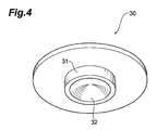
FIG. 4 is a perspective view illustrating a cap illustrated in FIG. 1.
FIG. 5 is a sectional view along line V-V of FIG. 2.
FIG. 6 is a sectional view illustrating a state where claw parts illustrated in FIG. 5 are fixed.
FIG. 7 is a perspective view illustrating a microneedle array.
FIG. 8 is a view illustrating a case where an auxiliary tool is employed in use of the applicator illustrated in FIG. 1.
FIG. 9 is a view illustrating how to use the applicator illustrated in FIG. 1.
FIG. 10 is a graph illustrating relations between momentums of the pistons and transfer rates of ovalbumin (OVA) in accordance with an example.
FIG. 11 is a graph illustrating relations between kinetic energy density of the pistons and transfer rates of OVA in accordance with the example.
FIG. 12 is another graph illustrating a relation between momentums of the piston and transfer amounts of OVA in accordance with the example.
FIG. 13(a) is a perspective view illustrating an applicator in accordance with a modified embodiment, and FIG. 13(b) is a sectional view along line B-B of FIG. 13(a).
FIG. 14 is a perspective view illustrating an applicator in accordance with another modified embodiment.
FIG. 15 is a sectional view along line XV-XV of FIG. 14.
DESCRIPTION OF EMBODIMENTS
Embodiments according to the present invention will now be described in detail with reference to the accompanying drawings. In the explanation of the drawings, same or similar components are denoted by the same reference numerals, and an overlapping explanation thereof will be omitted.
A structure of an applicator 10 in accordance with the embodiment will be described first with reference to FIGS. 1 to 6. FIG. 1 is a perspective view illustrating the applicator 10 from the upper part. FIG. 2 is a perspective view illustrating the applicator 10 from the lower part. FIG. 3 is a perspective view illustrating a piston 20. FIG. 4 is a perspective view illustrating a cap 30. FIG. 5 is a sectional view along line V-V of FIG. 2, and FIG. 6 is a sectional view illustrating a state where claw parts illustrated in FIG. 5 are fixed.
A housing 11 of the applicator 10 has a cylindrical shape. In the applicator 10, the shape of the housing may be changed or a housing surface may be processed in consideration of ease of holding the housing, and easiness of applying micro projections (microneedles) to a skin. For example, a tubular housing having a polygonal cross-section shape may be used, an outer wall may be rounded as a whole, or recesses or steps may be provided to a cylindrical housing. Fine grooves may be formed on or coating may be applied on a surface of the housing in order to prevent slipping.
The piston 20 for making an impact on a microneedle array put on a skin is stored in the vicinity of one end of the housing 11 (see FIG. 2). The cap 30 for activating the piston 20 is stored in the vicinity of the other end of the housing 11 (see FIG. 1). Hereinafter, the side where the cap 30 is stored is defined as the upper side of the applicator 10 or the housing 11, whereas the side where the piston 20 is stored is defined as the lower side of the applicator 10 or the housing 11. An annular member 11 a is fitted into the upper end of the housing 11, and the lower end of the housing 11 is formed in a tapered shape expanding toward its downside.
The piston 20 is a transmission member that includes a disk-shaped piston plate 21 colliding with the microneedle array, and a plurality of piston rods 22 as illustrated in FIG. 3. The piston rods 22 extend from the vicinity of the center of the upper surface of the piston plate 21 in the direction orthogonal to the upper surface thereof. A plurality of air holes 21 a for releasing air are provided to the piston plate 21, thereby reducing air resistance and reducing the weight of the piston 20. Hook-shaped claw parts 22 a projecting outside in a diameter direction of the piston plate 21 each are provided to the tip ends of the respective piston rods 22. The claw parts 22 a are formed in a tapered shape narrowing toward the tip ends of the piston rods 22.
The shape of the cap 30 is disk-shaped as illustrated in FIG. 4, and its diameter is substantially the same as the inner diameter of the housing 11. A cylindrical projection part 31 is provided on the center of the lower surface of the cap 30, and a recessed part 32 is provided to the projection part 31. A shape of the recessed part 32 is conical so as to receive the claw parts 22 a of the piston rods 22.
A partition wall 12 for partitioning the inside of the housing 11 into the upper side part and the lower side part is provided in the vicinity of the upper part inside the housing 11 as illustrated in FIG. 5. Hereinafter, a space over the partition wall 12 is referred to as an upper part space 14, whereas a space thereunder is referred to as a lower part space 15. The center of the partition wall 12 has a round through hole 13. An inner cylinder 16 is attached to the through hole 13 in a state of being inserted from under the through hole 13 to the middle thereof. The inner wall of the inner cylinder 16 is formed in a tapered shape expanding toward its downside, and serves for guiding vertical motion of the piston rods 22.
The upper part of the through hole 13 serves for guiding the projection part 31 of the cap 30, and the diameter of the upper part is the same as that of the projection part 31. The upper end of the inner cylinder 16 positioned in the vicinity of the center of the through hole 13 serves for fixing the piston 20, being engaged with the claw parts 22 a of the piston rods 22. Hereinafter, the upper end of the inner cylinder 16 is referred to as a claw receiving part 17.
The lower part space 15 stores the piston 20, a compression spring (biasing member or elastic member; hereinafter, simply referred to as “spring”) 40 providing biasing force to the piston 20, and an annular spring base (support base) 50 supporting the spring 40 from under thereof. A plurality of guides 60 for sliding the spring base 50 within a predetermined range in the vertical direction are provided on the inner wall of the lower part space 15.
Each of the guides 60 extends from the lower end of the housing 11 to the vicinity of the lower end of the inner cylinder 16, and a substantially lower half area of each guide 60 (lower part of the guide 60) is wider than the remaining upper half area (upper part of the guide 60). Notches (not illustrated) for engaging with the upper part of the guides 60 are provided on the outer periphery of the spring base 50. This structure allows the spring base 50 to slide within the upper part of the guides 60 in the vertical direction. The spring 40 is stored in the lower part space 15 so as to surround the inner cylinder 16. The upper end of the spring 40 is attached to the lower surface of the partition wall 12, whereas the lower end thereof is in contact with the upper surface of the spring base 50. In the embodiment, a column coil spring may be used as the spring 40 as illustrated in FIG. 5.
The piston 20 is stored in the lower part space 15 after the spring 40 and the spring base 50 are stored in the lower part space 15. The diameter of the piston plate 21 is substantially the same as the inner diameter of the housing 11 limited by the lower part of the guides 60. The diameter of the piston plate 21 is larger than the inner diameter of the spring base 50, and the piston plate 21 is always positioned lower than the spring base 50.
The piston 20 can be fixed in a state of resisting the biasing force of the spring 40 in the lower part space 15. When the piston plate 21 is pushed from the outside of the housing 11 against the biasing force of the spring 40 in an initial state of the applicator 10 (see FIG. 5), the claw parts 22 a of the respective piston rods 22 pass through the inner cylinder 16, and are hooked to the claw receiving part 17 as illustrated in FIG. 6. This allows the piston 20 to be fixed in a state of resisting the biasing force of the spring 40.
The cap 30 is stored in the upper part space 14 with the projection part 31 facing the partition wall 12. When the whole cap 30 is stored in this manner, the annular member 11 a is attached to an end part thereof. This can prevent the cap 30 from jumping out of the housing 11.
The position of the cap 30 is not fixed in the upper part space 14, and the cap 30 can freely move along an extending direction (vertical direction) of the housing 11 in the upper part space 14. When the applicator 10 is inclined so that the cap 30 is positioned higher than the piston 20, which is fixed in a state of resisting the biasing force of the spring 40, the projection part 31 of the cap 30 is in contact with the claw parts 22 a of the piston 20 as illustrated in FIG. 6. In other words, the cap 30 is provided freely movable along the extending direction of the housing 11 in the upper part space 14 so that the projection part 31 can be in contact with the claw parts 22 a when the piston 20 is fixed by the claw parts 22 a.
Examples of parameters related to energy of the piston 20 activated by the biasing force of the spring 40 include a transverse elasticity modulus, a wire diameter, the number of windings, an average coil diameter, a distance indicating how long the spring 40 is shortened from its natural length, the speed of the piston, the mass of the spring, and the mass of the piston.
The transverse elasticity modulus is determined by a material of the spring, and is 68500 N/mm2 when the material is stainless and is 78500 N/mm2 when the material is a piano wire (steel). Estimated values of the other parameters are as follows. The wire diameter is from 0.1 to 5 mm, the number of windings is from 1 to 20, the average coil diameter is from 1 to 30 mm, the distance is from 1 to 100 mm, the speed is from 0.1 to 50 m/s, the mass of the spring is from 0.1 to 5 g, and the mass of the piston is from 0.1 to 20 g. In the embodiment, the mass of the piston may be 1.5 g or less.
Theoretical formulae related to the spring and the piston are defined with the parameters below. Equation (1) indicates a relation between the spring constant, the shape of the spring, and the material; Equation (2) indicates a relation between the mass and the size of the spring; Equation (3) indicates a relation between the spring energy and the kinetic energy; and Equation (4) indicates a relation between the speed, the energy, and the mass of the piston. In the following formulae, “G” indicates the transverse elasticity modulus (N/m2); “d” indicates the wire diameter (m); “n” indicates the number of windings; “D” indicates the average coil diameter (m); “k” indicates the spring constant (N/m); “x” indicates the distance (m); “v” indicates the speed (m/s); “l” indicates the length of the spring in its extension (m); “ρ” indicates the density (kg/m3); “m” indicates the mass of the spring (kg); and “M” indicates the mass of the piston (kg). In the description, the kinetic energy is considered to be the same as energy (puncture energy) when the micro projections (microneedles) puncture skin.
[ Math . 1 ] k = G d 4 8 n D 3 ( 1 ) [ Math . 2 m = ρ π l d 2 4 ( 2 ) [ Math . 3 ] E = 1 2 k x 2 = 1 2 M v 2 ( 3 ) [ Math . 4 ] v = 2 E M ( 4 )
The size of the applicator 10 can be determined depending on the size of the microneedle array below, however, how to determine the size is not limited to as follows.
When a lower side opening part of the housing 11 is shaped to fit the shape of the microneedle array and the minimum inner diameter of the opening part is adjusted to fit the outer diameter of the microneedle array, the size of the applicator 10 can be reduced depending on the size of the microneedle array. If the lower side opening part is formed in this manner, the applicator 10 is not shifted to the diameter direction (width direction) against the microneedle array when positioned on the microneedle array. The applicator 10, thus, enables the piston 20 to be applied to the microneedle array while keeping a positional relation parallel to the microneedle array. This allows puncture to be surely performed (improves the reproducibility of puncture).
A material of the applicator is not limited, but is preferably the one that has strength capable of keeping the biasing force of the spring 40. Examples of the material are as follows. Examples of the material of the housing 11 or the cap 30 can include a synthetic resin material such as acrylonitrile-butadiene-styrene (ABS) resin, polystyrene, polypropylene, and polyacetal (POM), a natural resin material, silicon, silicon dioxide, ceramic, and metal (such as stainless, titanium, nickel, molybdenum, chromium, and cobalt). The piston 20 may be produced using the same material as that of the microneedle array.
Air holes may be provided to the housing 11 and the cap 30 similarly to the piston plate 21. This can reduce air resistance of the cap 30 and reduce the weight of the applicator 10.
The following describes the structure of a microneedle array 90 used together with the applicator 10 with reference to FIG. 7. FIG. 7 is a perspective view illustrating the microneedle array 90.
The microneedle array 90 includes a substrate 91 and a plurality of micro projections (needles, in other words, microneedles) 92 two-dimensionally arranged on the substrate 91.
The substrate 91 is a base for supporting the micro projections 92. FIG. 7 illustrates the rectangular substrate 91, but the shape of the substrate 91 is not limited to this and may be round, for example. The micro projections 92 are arranged in zigzag (alternately) at substantially equal intervals on a surface of the substrate 91. A plurality of through holes may be provided to the substrate 91 so as to administer bioactive agents from the back side of the substrate 91 through the through holes. The area of the substrate 91 may be from 0.5 cm2 to 10 cm2, from 1 cm2 to 5 cm2, or from 1 cm2 to 3 cm2. Several substrates 91 may be connected so as to obtain a substrate of a desired size.
Each of the micro projections 92 is a tapered structure narrowing from its bottom part connected to the substrate 91 toward its tip. The tip ends of the respective micro projections may be sharpened or unsharpened. FIG. 7 illustrates the conical micro projections 92, but micro projections having a polygonal pyramid shape such as a square pyramid may be used. The height (length) of the micro projections 92 may be from 20 to 400 μm or from 50 to 300 μm.
One to ten micro projections 92 per 1 mm are provided in one column. An interval between adjacent columns is substantially equal to an interval between adjacent micro projections 92 in one column. The density (needle density) of the micro projections 92, thus, is from 100 to 10000 needles/cm2. The lower limit of the needle density may be 200 needles/cm2, 300 needles/cm2, 400 needles/cm2, or 500 needles/cm2. The upper limit of the needle density may be 5000 needles/cm2, 2000 needles/cm2, or 850 needles/cm2.
Coating of the active agents is applied on the substrate 91 and/or the micro projections 92. The coating is the one in which a coating liquid including the active agent is fixed on a part or the whole of the micro projections 92 and/or the substrate 91. A term “fixed” means to keep a state where an object is approximately uniformly coated with the coating liquid. The coating is applied in a prescribed range including the top of the micro projections 92. This range varies depending on the height of the micro projections 92, and may be from 0 to 500 μm, from 10 to 500 μm, or from 30 to 300 μm. The thickness of the coating may be less than 50 μm, less than 25 μm, or from 1 to 10 μm. The thickness of the coating is an average thickness measured over the surface of the micro projections 92 after drying. The thickness of the coating can be increased by applying a plurality of films of a coating carrier, in other words, by repeating a coating process after the coating carrier is fixed.
The following describes how to use the applicator 10 with reference to FIGS. 8 and 9. FIG. 8 is a view illustrating a case where an auxiliary tool H is employed in use of the applicator 10. FIG. 9 is a view illustrating how to use the applicator 10.
The initial state of the applicator 10 is as illustrated in FIG. 5. The piston 20 in an initial state is pushed inside the applicator 10 by a finger, and the piston 20 is fixed in a state of resisting the biasing force of the spring 40. The piston 20 may be pushed up by a hand or may be pushed up by the auxiliary tool H as illustrated in FIG. 8. The shape of the auxiliary tool H is not limited to an example in FIG. 8. The applicator 10 in which the piston 20 is fixed becomes a state illustrated in FIG. 6. The inner wall of the inner cylinder 16 is formed in a tapered shape narrowing toward the upper end (claw receiving part 17). This allows the user to engage the claw parts 22 a with the claw receiving part 17 by a less force and easily fix the piston 20. The user can recognize the completion of fixing with a “clicking” sound. The force to be applied when the piston 20 is fixed can be strengthened or weakened by adjusting an inclination of the tapered shape of the inner cylinder 16.
Subsequently, the applicator 10 is positioned and kept on the microneedle array 90 put on a skin S, and the cap 30 is pushed inside the applicator 10 by a finger (is pushed in an arrow A direction) as illustrated in FIG. 9. The microneedle array 90 may be attached to the skin with a cover agent C before the applicator 10 is positioned as illustrated in FIG. 9.
When the cap 30 is pushed, the projection part 31 provided to its lower surface pushes the claw parts 22 a of the respective piston rods 22 toward the center of the through hole 13, so that the engagement between the claw parts 22 a and the claw receiving part 17 is released. This causes the fixed state of the piston 20 to be released and allows the piston 20 to move toward the outside of the applicator 10 with the biasing force of the spring 40. The spring base 50 slides within the upper part of the guides 60. Thus, the piston 20 receives the biasing force of the spring 40 (the piston 20 is pushed in the second section by the spring base 50) within a section along the upper part of the guides 60 (second section) through the spring base 50 to move. After the spring base 50 stops at the lower end in the second section, the piston 20 moves in a section along the lower part of the guides 60 (first section) without receiving the biasing force of the spring 40 and collides with the microneedle array 90 at the lower end of the applicator 10 (see FIG. 9).
Thus, it is conceivable that the projection part 31 is a release mechanism for releasing the piston 20 fixed in a state of resisting the biasing force of the spring 40. Since the conical recessed part 32 is provided to the projection part 31, the claw parts 22 a is drawn along the conical shape and the piston 20 (applicator 10) is activated only when a certain force is applied to the cap 30. Thus, a constant impact is made if anyone carries out administration. This allows puncture to be surely performed (improves the reproducibility of puncture).
A force necessary for releasing the piston 20 can be adjusted by changing the shape of the recessed part 32 and the shape of the claw parts 22 a. For example, if the inclination of the tapered shape of the claw parts 22 a is made steep and the inclination of the conical shape of the recessed part 32 is adjusted corresponding thereto, the piston 20 can be released from the fixed state by a small force.
The collision transmits an biasing force of the spring 40 to the microneedle array 90 through the piston 20, whereby the micro projections 92 puncture the skin. The active agents applied on the microneedle array 90 are administered to a body through the micro projections 92.
After the use of the applicator 10 in this manner, the piston 20 can be fixed again in a state of resisting the biasing force of the spring 40 by being pushed inside the applicator 10. The applicator 10, thus, can be used repeatedly.
As described above, in the embodiment, the piston 20 transmitting biasing force necessary for puncture to the microneedle array 90 is very light, and the user feels less impact during operation of the applicator 10. The user, therefore, can administer the active agent using the applicator 10 without fear. In addition, even if the piston 20 is lightened in order not to give fear to the user, the active agent can be effectively administered by properly setting the momentum of the piston 20 and the needle density of the micro projections 92.
EXAMPLE
The present invention will now be specifically described based on embodiments, but is not limited to them at all. The following embodiment shows some examples about the mass and the momentum of the piston and the needle density of the micro projections (microneedles).
Puncture performance was evaluated using the applicator and the microneedle array described in the embodiment. The spring included in the applicator was a column coil spring that was approximately 20 mm in length in an extending state (the height of the spring in an extending state is referred to “free height”) and was approximately 10 mm in length in a compressed state. The puncture performance was evaluated by administering ovalbumin (OVA) to a human skin (in vitro) with the microneedle array so as to obtain the transfer amount of OVA to the human skin. The transfer amount means an amount that is administered to the skin out of OVA fixed on the micro projections.
There were prepared four types of pistons each having different mass as follows: 0.9802 g; 1.1906 g; 1.6509 g; and 2.8603 g. There were prepared a plurality of kinds of springs each having different spring constants in order to obtain various momentum P for the respective pistons. Herein, the momentum P (N·s) of the piston is represented by “P=my”, where “m” is the mass of the piston (kg) and “v” is the speed of the piston (m/s). The momentum P of the piston is an index for puncture energy when the micro projections (microneedles) collide with the human skin.
There were prepared three types of polylactic acid microneedle arrays (array A, array B, and array C). In each of the microneedle arrays, the height of the micro projection was 500 μm, and the area of the flat part at its tip was from 64 to 144 μm2. In each of the microneedle arrays, the coating range was approximately 180 μm including the top of the micro projections when OVA was applied on the respective micro projections. The differences among three types of microneedle arrays are the number of micro projections, the area of the substrate, the needle density, and an initial content (total amount) of OVA. Specific values are as shown in Table 1.
TABLE 1
Array A Array B Array C
Number of micro 640 640 1336
projections
Area of substrate (cm2) 1.13 2.26 2.26
Needle density 566 283 591
(needles/cm2)
Initial content (μg) 51 44 96
After the microneedle array in a state where the micro projections were coated with OVA was left still on the human skin and the applicator was positioned against the microneedle array, OVA was administered to the human skin by activating the applicator to make the piston plate collide with the microneedle array. The microneedle array removed from the human skin after the administration of OVA was soaked in phosphate buffered saline (PBS) so as to extract OVA. The amount of the extracted OVA was subtracted from the initial applied amount so as to obtain the transfer amount and the transfer rate. The speed of the activated piston was measured by a laser displacement gauge called LK-H150, which was made by Keyence corporation. Results shown in FIGS. 10 and 11 were obtained by applying this experiment to various combinations of the piston, the spring, and the microneedle array.
A graph in FIG. 10 illustrates transfer rates of OVA in relation with momentums of the pistons. The transfer rate of OVA was obtained by variously changing the combination of the piston and the spring in the microneedle array (i.e., array A) having the substrate area of 1.13 cm2 and 640 micro projections. In this graph, an area P surrounded by a dashed line shows the preferred transfer rate. This area P corresponds approximately to a case where the mass of the piston is 1.5 g or less and the momentum of the piston is from 0.0083 (N·s) to 0.015 (N·s).
A graph in FIG. 11 illustrates transfer rates of OVA in relation with kinetic energy density. The transfer rate of OVA was obtained by variously changing the combination of the piston and the spring in the microneedle array having the substrate area of 1.13 cm2 and 640 micro projections (i.e., array A). In other words, in the graph in FIG. 11, the abscissa in FIG. 10 is replaced with the kinetic energy density. It was predicted that the transfer rate and the kinetic energy density correspond to each other by one to one (that is, they indicate a proportional relation and have data plotted on the almost same straight line). However, it has been found that, even if the kinetic energy density is the same, the transfer rate may be different depending on the mass and the speed of the piston as illustrated in FIG. 11. Specifically, it has been found that the higher transfer rate can be obtained when a light piston collides with the microneedle array at high speed, compared with a case when a heavy piston collides with the microneedle array at low speed.
A graph in FIG. 12 illustrates transfer amounts of OVA obtained by changing microneedle arrays and springs against a piston having a mass of 1.1906 g. This graph shows that the transfer amount is preferable when the needle density was 500 needles/cm2 or more (when the array A or array C was used). It has been also found that, when the needle density is 500 needles/cm2 or more, the transfer amount is proportional to the momentum of the piston.
The present invention has been described in detail based on the embodiment thereof, but it should be noted that the present invention is not limited to the embodiment. Various changes and modifications can be made without departing from the spirit and scope of the present invention.
In the embodiment, the piston 20 moves toward the microneedle array without receiving the biasing force of the spring 40 in a part of the movement section, but the piston may keep receiving biasing force in the whole movement section (in other words, all during operation). For example, the present invention can be applied to an applicator 100 in which the lower end of a spring (biasing member) 140 is in contact with the upper surface of a piston plate 121 as illustrated in FIG. 13. In this case, a cap 130 is pushed in the same manner as the case of the applicator 10 so as to activate a piston (transmission member) 120, whereby the piston 120 is continuously pushed by the spring 140 until the piston 120 reaches the lower end of the applicator 100.
The present invention can be applied to an applicator 200 illustrated in FIGS. 14 and 15. The applicator 200 includes a main body 211 and a cap 230. The main body 211 stores a piston 220 transmitting the biasing force of a spring 240 to the microneedle array. The piston 220 includes a rod-like member 222 activated by the spring 240 and a transmission plate (transmission member) 221 provided to the lower end part of the rod-like member 222. The transmission plate 221 is not fixed to but hooked to the rod-like member 222 in a state of imparting a shaft directional play of the rod-like member 222. When the piston 220 is activated by the spring (biasing member) 240, first the rod-like member 222 and the transmission plate 221 integrally move downward. Then, the transmission plate 221 continuously drops to the lower end of the applicator 200 and transmits the biasing force of the spring 240 to the microneedle array, whereas the lower end of the rod-like member 222 stops above the lower end of the applicator 200. For details on the applicator 200, refer to the description of Japanese Patent Application No. 2011-164723 that the applicant filed prior to this application.
The spring is used as the biasing member in the embodiment, but the biasing member is not limited to this. For example, a mechanism in which a jet of compressed gas causes the piston to collide with the microneedle array may be adopted as the biasing member.
The microneedle array 90 and the applicator 10 are independent in the embodiment, but the microneedle array 90 may be integrated with the applicator 10. Specifically, the microneedle array 90 may be integrated with the surface of the piston plate 21 (surface opposite to the piston rods 22). Examples of integrating the microneedle array 90 with the piston plate 21 include a case in which the microneedle array 90 is bonded to the piston plate 21 by an adhesive or other means, a case in which the microneedle array 90 is mechanically fitted to the piston plate 21 by a claw member or other members, and a case in which micro projections (microneedles) are directly formed on the piston plate 21 using integral forming or other methods.
REFERENCE SIGNS LIST
10 . . . applicator, 11 . . . housing, 20 . . . piston, 30 . . . cap, 40 . . . spring, 90 . . . microneedle array, 92 . . . micro projections (microneedles), 100 . . . applicator, 120 . . . piston, 130 . . . cap, 140 . . . spring, 200 . . . applicator, 220 . . . piston, 230 . . . cap, 240 . . . spring.

Claims (3)

The invention claimed is:
1. An applicator applying microneedles to a skin, the applicator comprising:
a transmission member that transmits biasing force of a biasing member to a microneedle array including microneedles with a needle density of 500 needles/cm2 or more, wherein
a mass of the transmission member is 1.5 g or less,
the biasing member is an elastic member,
the transmission member moves without receiving the biasing force of the elastic member in a first section forming a part of a movement section in which the transmission member moves toward the skin,
a momentum of the transmission member activated by the biasing force of the biasing member is from 0.0083 (N·s) to 0.015 (N·s), wherein
the applicator further comprises a support base supporting the elastic member and transmits the biasing force to the transmission member in a second section different from the first section, and wherein
the support base pushing the transmission member with the biasing force stops at one end of the second section, whereby the transmission member moves without receiving the biasing force in the first section.
2. The applicator according to claim 1, wherein a transfer amount of an active agent applied on the microneedles to the skin is proportional to the momentum of the transmission member.
3. The applicator according to claim 1, wherein the biasing member is a column coil spring.
US14/349,523 2011-10-06 2012-10-02 Applicator Active US9498611B2 (en)

Applications Claiming Priority (4)

Application Number Priority Date Filing Date Title
JP2011222236 2011-10-06
JPP2011-222236 2011-10-06
JP2011-222236 2011-10-06
PCT/JP2012/075534 WO2013051568A1 (en) 2011-10-06 2012-10-02 Applicator

Publications (2)

Publication Number Publication Date
US20140243747A1 US20140243747A1 (en) 2014-08-28
US9498611B2 true US9498611B2 (en) 2016-11-22

Family

ID=48043725

Family Applications (1)

Application Number Title Priority Date Filing Date
US14/349,523 Active US9498611B2 (en) 2011-10-06 2012-10-02 Applicator

Country Status (5)

Country Link
US (1) US9498611B2 (en)
EP (1) EP2764887B1 (en)
JP (1) JP6265740B2 (en)
TW (1) TW201330893A (en)
WO (1) WO2013051568A1 (en)

Cited By (3)

* Cited by examiner, † Cited by third party
Publication number Priority date Publication date Assignee Title
US10391290B2 (en) 2013-05-31 2019-08-27 3M Innovative Properties Company Microneedle injection apparatus comprising a dual cover
US10945759B2 (en) 2017-12-28 2021-03-16 Refine Usa, Llc Microneedle device
US11896261B2 (en) 2014-11-14 2024-02-13 Cytrellis Biosystems, Inc. Devices and methods for ablation of the skin

Families Citing this family (21)

* Cited by examiner, † Cited by third party
Publication number Priority date Publication date Assignee Title
GB0402131D0 (en) 2004-01-30 2004-03-03 Isis Innovation Delivery method
AU2008341030B2 (en) 2007-12-24 2014-04-17 Vaxxas Pty Limited Coating method
US9943673B2 (en) 2010-07-14 2018-04-17 Vaxxas Pty Limited Patch applying apparatus
AU2012323782B2 (en) 2011-10-12 2017-04-06 Vaxxas Pty Limited Delivery device
CN104245041B (en) * 2012-04-05 2016-08-17 久光制药株式会社 Sting device and manufacture method thereof
KR102158891B1 (en) 2012-12-21 2020-09-22 히사미쓰 세이야꾸 가부시키가이샤 Applicator
BR112016002695B1 (en) * 2013-08-09 2022-09-20 Cytrellis Biosystems, Inc DEVICE WITH AN ABLATIVE DEVICE, A REMOVAL DEVICE AND A POSITIONING DEVICE
WO2015040697A1 (en) * 2013-09-18 2015-03-26 コスメディ製薬株式会社 Microneedle patch application device and patch holder
JP6215343B2 (en) 2013-11-05 2017-10-18 久光製薬株式会社 applicator
CA3204959A1 (en) 2015-02-02 2016-08-11 Vaxxas Pty Limited Microprojection array applicator and method
JP2017023404A (en) * 2015-07-22 2017-02-02 日本写真印刷株式会社 Impact-application-type applicator for microneedle patch and tip member
EP3345648A4 (en) * 2015-09-02 2019-04-17 Hisamitsu Pharmaceutical Co., Inc. Applicator
US11103259B2 (en) 2015-09-18 2021-08-31 Vaxxas Pty Limited Microprojection arrays with microprojections having large surface area profiles
CA2999538A1 (en) * 2015-09-28 2017-04-06 Vaxxas Pty Limited Microprojection arrays with enhanced skin penetrating properties and methods thereof
DK3606760T3 (en) 2017-03-31 2023-11-06 Vaxxas Pty Ltd ARRANGEMENT AND PROCEDURE FOR COATING SURFACES
US11175128B2 (en) 2017-06-13 2021-11-16 Vaxxas Pty Limited Quality control of substrate coatings
EP4218893A1 (en) 2017-08-04 2023-08-02 Vaxxas Pty Limited Compact high mechanical energy storage and low trigger force actuator for the delivery of microprojection array patches (map)
JP7172293B2 (en) * 2018-08-30 2022-11-16 ニプロ株式会社 microneedle applicator
CN112888474A (en) * 2018-08-30 2021-06-01 尼普洛株式会社 Microneedle applicator
JP7099189B2 (en) * 2018-08-30 2022-07-12 ニプロ株式会社 Microneedle applicator
DE102019200557A1 (en) * 2019-01-17 2020-07-23 Lts Lohmann Therapie-Systeme Ag Applicator

Citations (56)

* Cited by examiner, † Cited by third party
Publication number Priority date Publication date Assignee Title
US1033099A (en) 1911-12-11 1912-07-23 John W Harrison Drill-socket.
US2932277A (en) 1957-10-28 1960-04-12 John E Borah Moistening device
US4526171A (en) 1980-01-15 1985-07-02 Schachar Ronald A Cornea incision device
US4589412A (en) 1984-01-03 1986-05-20 Intravascular Surgical Instruments, Inc. Method and apparatus for surgically removing remote deposits
US4747842A (en) 1987-06-22 1988-05-31 David Dietz Article for applying styptic to a dog's bleeding nail
US5026388A (en) 1989-09-26 1991-06-25 Ingalz Thomas J Single-use skin puncture device
US5904664A (en) 1996-05-18 1999-05-18 Kim; Jin Sup Mugwort moxacautery device
WO2000009184A1 (en) 1998-08-13 2000-02-24 Imprint Pharmaceuticals Limited Apparatus for delivering a substance having one or more needles driven at high velocity
US6298863B1 (en) 2000-07-25 2001-10-09 Young Kwang Byun Cosmetic case having a brush with a sliding cap
WO2002030300A2 (en) 2000-10-13 2002-04-18 Alza Corporation Microprotrusion member retainer for impact applicator
US20020077584A1 (en) * 1999-12-16 2002-06-20 Wei-Qi Lin Device and method for enhancing transdermal flux of agents being sampled
US20020087182A1 (en) 2000-10-13 2002-07-04 Trautman Joseph C. Microblade array impact applicator
US20020123675A1 (en) 2000-10-13 2002-09-05 Trautman Joseph C. Apparatus and method for piercing skin with microprotrusions
US20040087893A1 (en) 2002-06-25 2004-05-06 Sung-Yun Kwon Solid solution perforator for drug delivery and other applications
US6743211B1 (en) 1999-11-23 2004-06-01 Georgia Tech Research Corporation Devices and methods for enhanced microneedle penetration of biological barriers
US20050096586A1 (en) 2003-10-31 2005-05-05 Trautman Joseph C. Self-actuating applicator for microprojection array
JP2005533625A (en) 2002-07-19 2005-11-10 スリーエム イノベイティブ プロパティズ カンパニー Microneedle device and microneedle delivery device
WO2005123173A1 (en) 2004-06-10 2005-12-29 3M Innovative Properties Company Patch application device and kit
US20060142691A1 (en) * 2000-10-13 2006-06-29 Trautman Joseph C Apparatus and method for piercing skin with microprotrusions
JP2006341089A (en) 2005-05-13 2006-12-21 Fujikura Ltd Instrument for carrying medicinal material and manufacturing method of the same
JP2007037626A (en) 2005-08-01 2007-02-15 Fujikura Ltd Equipment for delivering drug nontoxic to living body
US20070083151A1 (en) 2003-12-29 2007-04-12 Carter Chad J Medical devices and kits including same
US20070233011A1 (en) 2006-03-13 2007-10-04 Kei Hagino Micropore forming system, micropore forming device, chip container, and chip container kit
JP2007260351A (en) 2006-03-30 2007-10-11 Fujikura Ltd Medicine carrying device, method for manufacturing the same, and method for manufacturing die for manufacturing the medicine carrying device
US20070250018A1 (en) 2004-08-12 2007-10-25 Hirotoshi Adachi Transdermal Drug Administration System with Microneedles
US20070255251A1 (en) 2006-03-10 2007-11-01 Alza Corporation Microprojection Array Application With High Barrier Retainer
US20070293816A1 (en) 2006-04-25 2007-12-20 Alza Corporation Microprojection Array Application with Grouped Microprojections for High Drug Loading
US20080009811A1 (en) 2004-11-18 2008-01-10 3M Innovative Properties Company Non-Skin-Contacting Microneedle Array Applicator
US20080114298A1 (en) 2004-11-18 2008-05-15 Cantor Adam S Low-Profile Microneedle Array Applicator
US7381003B1 (en) 2007-01-24 2008-06-03 Chia-Sheng Chang Applicator of cosmetic cream jar
US20080183144A1 (en) 2007-01-22 2008-07-31 Trautman Joseph C Applicators for microneedles
US20090030365A1 (en) 2006-02-10 2009-01-29 Hisamitsu Pharmaceutical Co., Inc. Transdermal Drug Administration Apparatus Having Microneedles
US20090099502A1 (en) 2006-04-07 2009-04-16 Hisamitsu Pharmaceutical Co., Inc. Microneedle Device And Transdermal Administration Device Provided With Microneedles
US20090130127A1 (en) 2005-08-01 2009-05-21 Seiji Tokumoto Adjuvant or Pharmaceutical Preparation for Transdermal or Transmucousal Administration
USD598173S1 (en) 2008-06-13 2009-08-11 Hartel David D Tool for cleaning the outer surface of a tube
US20090216215A1 (en) 2006-08-24 2009-08-27 Christian Thalmann Insertion device for insertion heads and infusion sets
US20100030100A1 (en) 2007-02-06 2010-02-04 Hisamitsu Pharmaceutical Co., Inc. Microneedle Device For Diagnosis Of Allergy
CN100591386C (en) 2002-06-25 2010-02-24 权圣润 Rapidly dissolving micro-perforator for drug delivery and other applications
US20100047327A1 (en) 2007-01-31 2010-02-25 Tetsuji Kuwahara Adjuvant for Transdermal or Transmucosal Administration and Pharmaceutical Preparation Containing the Same
USD612939S1 (en) 2008-07-29 2010-03-30 Envy Medical, Inc. Microdermabrasion treatment tip mount
US20100221314A1 (en) 2007-10-18 2010-09-02 Hisamitsu Pharmaceutical Co., Inc. Microneedle Device
US20100249651A1 (en) 2009-03-31 2010-09-30 Sysmex Corporation Puncture device and fine pore formation method
US20100280457A1 (en) 2007-05-15 2010-11-04 Hisamitsu Pharmaceutical Co., Inc. Method Of Coating Microneedle
US7914813B2 (en) 2004-02-03 2011-03-29 Hisamitsu Pharmaceutical Co., Inc. Interface for transdermal drug administration device
JP2011078711A (en) 2009-10-05 2011-04-21 Kosumedei Seiyaku Kk Microneedle array administration device using magnetic repulsion
US20110112509A1 (en) 2008-06-30 2011-05-12 Hisamitsu Pharmaceutical Co., Inc. Microneedle device, and method for enhancing the efficacy of influenza vaccine by using microneedle device
US20110172639A1 (en) 2010-01-08 2011-07-14 Ratio, Inc. Device and method for delivery of microneedle to desired depth within the skin
US7993871B2 (en) 2004-12-22 2011-08-09 Charm Sciences, Inc. Sampling method and device
WO2011105508A1 (en) 2010-02-24 2011-09-01 久光製薬株式会社 Micro-needle device and preparation method
US20110276027A1 (en) 2010-05-04 2011-11-10 Corium International, Inc. Applicators for microneedles
US20110276028A1 (en) 2010-05-04 2011-11-10 Corium International, Inc. Method and device for transdermal delivery of parathyroid hormone using a microprojection array
US20110319920A1 (en) 2010-06-24 2011-12-29 Kikkawa Yasuo Micropore forming apparatus and micropore forming method
WO2012046816A1 (en) 2010-10-07 2012-04-12 久光製薬株式会社 Applicator
US20120130306A1 (en) 2009-06-10 2012-05-24 Hisamitsu Pharmaceutical Co., Inc. Microneedle device
US20120136312A1 (en) 2009-07-23 2012-05-31 Toppan Printing Co., Ltd. Microneedle array
US20120330250A1 (en) 2010-02-24 2012-12-27 Hisamitsu Pharmaceutical Co., Inc. Micro-needle device

Family Cites Families (1)

* Cited by examiner, † Cited by third party
Publication number Priority date Publication date Assignee Title
JP2011164723A (en) 2010-02-04 2011-08-25 Tokai Rika Co Ltd Remote input device

Patent Citations (69)

* Cited by examiner, † Cited by third party
Publication number Priority date Publication date Assignee Title
US1033099A (en) 1911-12-11 1912-07-23 John W Harrison Drill-socket.
US2932277A (en) 1957-10-28 1960-04-12 John E Borah Moistening device
US4526171A (en) 1980-01-15 1985-07-02 Schachar Ronald A Cornea incision device
US4589412A (en) 1984-01-03 1986-05-20 Intravascular Surgical Instruments, Inc. Method and apparatus for surgically removing remote deposits
US4747842A (en) 1987-06-22 1988-05-31 David Dietz Article for applying styptic to a dog's bleeding nail
US5026388A (en) 1989-09-26 1991-06-25 Ingalz Thomas J Single-use skin puncture device
US5904664A (en) 1996-05-18 1999-05-18 Kim; Jin Sup Mugwort moxacautery device
JP2002522170A (en) 1998-08-13 2002-07-23 イムプリント ファーマスーティカルス リミテッド Device for feeding one or more needle shaking substances driven at high speed
WO2000009184A1 (en) 1998-08-13 2000-02-24 Imprint Pharmaceuticals Limited Apparatus for delivering a substance having one or more needles driven at high velocity
US6743211B1 (en) 1999-11-23 2004-06-01 Georgia Tech Research Corporation Devices and methods for enhanced microneedle penetration of biological barriers
US20020077584A1 (en) * 1999-12-16 2002-06-20 Wei-Qi Lin Device and method for enhancing transdermal flux of agents being sampled
US6298863B1 (en) 2000-07-25 2001-10-09 Young Kwang Byun Cosmetic case having a brush with a sliding cap
JP2004510535A (en) 2000-10-13 2004-04-08 アルザ・コーポレーシヨン Apparatus and method for piercing skin using microprojections
US7419481B2 (en) 2000-10-13 2008-09-02 Alza Corporation Apparatus and method for piercing skin with microprotrusions
US20020087182A1 (en) 2000-10-13 2002-07-04 Trautman Joseph C. Microblade array impact applicator
JP2004510534A (en) 2000-10-13 2004-04-08 アルザ・コーポレーシヨン Small projection member holder for impact application device
US20020123675A1 (en) 2000-10-13 2002-09-05 Trautman Joseph C. Apparatus and method for piercing skin with microprotrusions
WO2002030300A2 (en) 2000-10-13 2002-04-18 Alza Corporation Microprotrusion member retainer for impact applicator
JP4198985B2 (en) 2000-10-13 2008-12-17 アルザ・コーポレーシヨン Microblade array impact applicator.
US20060142691A1 (en) * 2000-10-13 2006-06-29 Trautman Joseph C Apparatus and method for piercing skin with microprotrusions
US20040087893A1 (en) 2002-06-25 2004-05-06 Sung-Yun Kwon Solid solution perforator for drug delivery and other applications
CN100591386C (en) 2002-06-25 2010-02-24 权圣润 Rapidly dissolving micro-perforator for drug delivery and other applications
US20050261631A1 (en) 2002-07-19 2005-11-24 3M Innovative Properties Company Microneedle devices and microneedle delivery apparatus
JP2005533625A (en) 2002-07-19 2005-11-10 スリーエム イノベイティブ プロパティズ カンパニー Microneedle device and microneedle delivery device
US20050096586A1 (en) 2003-10-31 2005-05-05 Trautman Joseph C. Self-actuating applicator for microprojection array
JP2007509706A (en) 2003-10-31 2007-04-19 アルザ・コーポレーシヨン Self-actuating applicator for microprojection arrays
US20070083151A1 (en) 2003-12-29 2007-04-12 Carter Chad J Medical devices and kits including same
JP2007516781A (en) 2003-12-29 2007-06-28 スリーエム イノベイティブ プロパティズ カンパニー Medical device and kit including the medical device
US7914813B2 (en) 2004-02-03 2011-03-29 Hisamitsu Pharmaceutical Co., Inc. Interface for transdermal drug administration device
WO2005123173A1 (en) 2004-06-10 2005-12-29 3M Innovative Properties Company Patch application device and kit
US20070250018A1 (en) 2004-08-12 2007-10-25 Hirotoshi Adachi Transdermal Drug Administration System with Microneedles
US20080114298A1 (en) 2004-11-18 2008-05-15 Cantor Adam S Low-Profile Microneedle Array Applicator
US20080009811A1 (en) 2004-11-18 2008-01-10 3M Innovative Properties Company Non-Skin-Contacting Microneedle Array Applicator
US7993871B2 (en) 2004-12-22 2011-08-09 Charm Sciences, Inc. Sampling method and device
JP2006341089A (en) 2005-05-13 2006-12-21 Fujikura Ltd Instrument for carrying medicinal material and manufacturing method of the same
JP2007037626A (en) 2005-08-01 2007-02-15 Fujikura Ltd Equipment for delivering drug nontoxic to living body
US20090130127A1 (en) 2005-08-01 2009-05-21 Seiji Tokumoto Adjuvant or Pharmaceutical Preparation for Transdermal or Transmucousal Administration
US20090030365A1 (en) 2006-02-10 2009-01-29 Hisamitsu Pharmaceutical Co., Inc. Transdermal Drug Administration Apparatus Having Microneedles
US20070255251A1 (en) 2006-03-10 2007-11-01 Alza Corporation Microprojection Array Application With High Barrier Retainer
US20070233011A1 (en) 2006-03-13 2007-10-04 Kei Hagino Micropore forming system, micropore forming device, chip container, and chip container kit
JP2007260351A (en) 2006-03-30 2007-10-11 Fujikura Ltd Medicine carrying device, method for manufacturing the same, and method for manufacturing die for manufacturing the medicine carrying device
US20090099502A1 (en) 2006-04-07 2009-04-16 Hisamitsu Pharmaceutical Co., Inc. Microneedle Device And Transdermal Administration Device Provided With Microneedles
US20070293816A1 (en) 2006-04-25 2007-12-20 Alza Corporation Microprojection Array Application with Grouped Microprojections for High Drug Loading
US20090216215A1 (en) 2006-08-24 2009-08-27 Christian Thalmann Insertion device for insertion heads and infusion sets
JP2010501211A (en) 2006-08-24 2010-01-21 エフ.ホフマン−ラ ロシュ アーゲー Puncture device for puncturing a puncture head such as an infusion set
US20080183144A1 (en) 2007-01-22 2008-07-31 Trautman Joseph C Applicators for microneedles
US7381003B1 (en) 2007-01-24 2008-06-03 Chia-Sheng Chang Applicator of cosmetic cream jar
US20100047327A1 (en) 2007-01-31 2010-02-25 Tetsuji Kuwahara Adjuvant for Transdermal or Transmucosal Administration and Pharmaceutical Preparation Containing the Same
US20100030100A1 (en) 2007-02-06 2010-02-04 Hisamitsu Pharmaceutical Co., Inc. Microneedle Device For Diagnosis Of Allergy
US20100280457A1 (en) 2007-05-15 2010-11-04 Hisamitsu Pharmaceutical Co., Inc. Method Of Coating Microneedle
US20100221314A1 (en) 2007-10-18 2010-09-02 Hisamitsu Pharmaceutical Co., Inc. Microneedle Device
USD598173S1 (en) 2008-06-13 2009-08-11 Hartel David D Tool for cleaning the outer surface of a tube
US20110112509A1 (en) 2008-06-30 2011-05-12 Hisamitsu Pharmaceutical Co., Inc. Microneedle device, and method for enhancing the efficacy of influenza vaccine by using microneedle device
CN102076357A (en) 2008-06-30 2011-05-25 久光制药株式会社 Microneedle device, and method for enhancing efficacy of influenza vaccine by using microneedle devive
USD612939S1 (en) 2008-07-29 2010-03-30 Envy Medical, Inc. Microdermabrasion treatment tip mount
US20100249651A1 (en) 2009-03-31 2010-09-30 Sysmex Corporation Puncture device and fine pore formation method
JP2010233803A (en) 2009-03-31 2010-10-21 Sysmex Corp Puncture instrument for forming micropore
US20120130306A1 (en) 2009-06-10 2012-05-24 Hisamitsu Pharmaceutical Co., Inc. Microneedle device
US20120136312A1 (en) 2009-07-23 2012-05-31 Toppan Printing Co., Ltd. Microneedle array
JP2011078711A (en) 2009-10-05 2011-04-21 Kosumedei Seiyaku Kk Microneedle array administration device using magnetic repulsion
US20110172639A1 (en) 2010-01-08 2011-07-14 Ratio, Inc. Device and method for delivery of microneedle to desired depth within the skin
WO2011105508A1 (en) 2010-02-24 2011-09-01 久光製薬株式会社 Micro-needle device and preparation method
US20120330250A1 (en) 2010-02-24 2012-12-27 Hisamitsu Pharmaceutical Co., Inc. Micro-needle device
US20130041330A1 (en) 2010-02-24 2013-02-14 Hisamitsu Pharmaceutical Co., Inc. Micro-needle device and preparation method
US20110276028A1 (en) 2010-05-04 2011-11-10 Corium International, Inc. Method and device for transdermal delivery of parathyroid hormone using a microprojection array
US20110276027A1 (en) 2010-05-04 2011-11-10 Corium International, Inc. Applicators for microneedles
US20110319920A1 (en) 2010-06-24 2011-12-29 Kikkawa Yasuo Micropore forming apparatus and micropore forming method
WO2012046816A1 (en) 2010-10-07 2012-04-12 久光製薬株式会社 Applicator
US20130226098A1 (en) 2010-10-07 2013-08-29 Hisamitsu Pharmaceutical Co., Inc. Applicator

Non-Patent Citations (10)

* Cited by examiner, † Cited by third party
Title
Chinese Patent Application No. 201380017762.6, Office Action dated Nov. 27, 2015, seven (7) pages.
European Patent Application No. 12838997.0, Search Report dated Nov. 11, 2015, seven (7) pages.
European Patent Application No. 13771861.5, Search Report dated Dec. 16, 2015, eleven (11) pages.
Japanese Patent Application No. P2012-537766, Notice of Allowance dated Feb. 2, 2016, three (3) pages.
PCT/JP2012/075534, International Search Report dated Nov. 20, 2012, one (1) page.
Taiwan Patent Application No. 101136676, Office Action dated Dec. 29, 2015, four (4) pages.
Taiwanese Design Patent Application No. 100301892, Notice of Allowance issued Nov. 14, 2011, four (4) pages.
WO Patent Application No. PCT/JP2011/073129, Search Report dated Nov. 22, 2011 six (6) pages.
WO Patent Application No. PCT/JP20111073129, International Preliminary Report on Patentability issued on May 16, 2013, Seven (7) pages.
WO Patent Application No. PCT/JP2012/075534, International Preliminary Report on Patentability dated Apr. 17, 2014, seven (7) Pages.

Cited By (3)

* Cited by examiner, † Cited by third party
Publication number Priority date Publication date Assignee Title
US10391290B2 (en) 2013-05-31 2019-08-27 3M Innovative Properties Company Microneedle injection apparatus comprising a dual cover
US11896261B2 (en) 2014-11-14 2024-02-13 Cytrellis Biosystems, Inc. Devices and methods for ablation of the skin
US10945759B2 (en) 2017-12-28 2021-03-16 Refine Usa, Llc Microneedle device

Also Published As

Publication number Publication date
JP6265740B2 (en) 2018-01-24
TWI561272B (en) 2016-12-11
EP2764887A1 (en) 2014-08-13
TW201330893A (en) 2013-08-01
EP2764887A4 (en) 2015-12-09
WO2013051568A1 (en) 2013-04-11
EP2764887B1 (en) 2020-12-02
JPWO2013051568A1 (en) 2015-03-30
US20140243747A1 (en) 2014-08-28

Similar Documents

Publication Publication Date Title
US9498611B2 (en) Applicator
EP2626107B1 (en) Applicator
JP5702384B2 (en) Hollow microneedle array
US9216252B2 (en) Applicator
AU2008241133B2 (en) Disposable injector comprising at least one draw hook and a sliding wedge-type gear for unlocking a locking element
CA2428510C (en) Blood withdrawal system
JP6487899B2 (en) Microprojection applicator
EP2766066B1 (en) Integrated microneedle array delivery system
CN106999660A (en) Automated injection device with the injection audible instruction of progress
JP2014525339A (en) Delivery system for hollow microneedle array
JP2016511105A (en) Multiple impact microprojection applicators and methods of use
JP5520303B2 (en) Needleless disposable syringe with high injection safety
MXPA05000597A (en) Microneedle devices and microneedle delivery apparatus.
KR20130103410A (en) Method and apparatus for insertion of a sensor
KR20180131575A (en) Scanning device
EP3067088B1 (en) Applicator
KR20230109662A (en) Applicator for intradermal microneedle array patch

Legal Events

Date Code Title Description
AS Assignment

Owner name: HISAMTSU PHARMACEUTICAL CO., INC., JAPAN

Free format text: ASSIGNMENT OF ASSIGNORS INTEREST;ASSIGNORS:TOKUMOTO, SEIJI;OGURA, MAKOTO;REEL/FRAME:032602/0359

Effective date: 20140403

AS Assignment

Owner name: HISAMITSU PHARMACEUTICAL CO., INC., JAPAN

Free format text: CORRECTIVE ASSIGNMENT TO CORRECT THE ASSIGNEE NAME PREVIOUSLY RECORDED ON REEL 032602 FRAME 0359. ASSIGNOR(S) HEREBY CONFIRMS THE ASSIGNMENT OF ASSIGNOR'S INTEREST;ASSIGNORS:TOKUMOTO, SEIJI;OGURA, MAKOTO;REEL/FRAME:032631/0462

Effective date: 20140403

STCF Information on status: patent grant

Free format text: PATENTED CASE

MAFP Maintenance fee payment

Free format text: PAYMENT OF MAINTENANCE FEE, 4TH YEAR, LARGE ENTITY (ORIGINAL EVENT CODE: M1551); ENTITY STATUS OF PATENT OWNER: LARGE ENTITY

Year of fee payment: 4