US9488330B2 - Direct aisle lighter - Google Patents
Direct aisle lighter Download PDFInfo
- Publication number
- US9488330B2 US9488330B2 US13/453,942 US201213453942A US9488330B2 US 9488330 B2 US9488330 B2 US 9488330B2 US 201213453942 A US201213453942 A US 201213453942A US 9488330 B2 US9488330 B2 US 9488330B2
- Authority
- US
- United States
- Prior art keywords
- lighting fixture
- side reflectors
- light
- mount
- elongated
- Prior art date
- Legal status (The legal status is an assumption and is not a legal conclusion. Google has not performed a legal analysis and makes no representation as to the accuracy of the status listed.)
- Active, expires
Links
- 230000003287 optical effect Effects 0.000 claims abstract description 31
- 230000009977 dual effect Effects 0.000 claims description 8
- 239000007787 solid Substances 0.000 abstract description 4
- 239000000463 material Substances 0.000 description 12
- OAICVXFJPJFONN-UHFFFAOYSA-N Phosphorus Chemical compound [P] OAICVXFJPJFONN-UHFFFAOYSA-N 0.000 description 8
- 239000003086 colorant Substances 0.000 description 7
- 230000007246 mechanism Effects 0.000 description 6
- 238000000034 method Methods 0.000 description 5
- 238000002156 mixing Methods 0.000 description 5
- 238000006243 chemical reaction Methods 0.000 description 4
- 238000004519 manufacturing process Methods 0.000 description 4
- 230000000694 effects Effects 0.000 description 3
- 239000004065 semiconductor Substances 0.000 description 3
- 229910052782 aluminium Inorganic materials 0.000 description 2
- XAGFODPZIPBFFR-UHFFFAOYSA-N aluminium Chemical compound [Al] XAGFODPZIPBFFR-UHFFFAOYSA-N 0.000 description 2
- 229910019990 cerium-doped yttrium aluminum garnet Inorganic materials 0.000 description 2
- 239000000975 dye Substances 0.000 description 2
- 230000003595 spectral effect Effects 0.000 description 2
- 238000001228 spectrum Methods 0.000 description 2
- 239000000853 adhesive Substances 0.000 description 1
- 230000001070 adhesive effect Effects 0.000 description 1
- 230000005540 biological transmission Effects 0.000 description 1
- 230000002301 combined effect Effects 0.000 description 1
- 239000004020 conductor Substances 0.000 description 1
- 238000001816 cooling Methods 0.000 description 1
- 230000002596 correlated effect Effects 0.000 description 1
- 238000004512 die casting Methods 0.000 description 1
- 238000009792 diffusion process Methods 0.000 description 1
- 230000005611 electricity Effects 0.000 description 1
- 230000003203 everyday effect Effects 0.000 description 1
- 238000001125 extrusion Methods 0.000 description 1
- 230000004907 flux Effects 0.000 description 1
- 229910052751 metal Inorganic materials 0.000 description 1
- 239000002184 metal Substances 0.000 description 1
- 239000000203 mixture Substances 0.000 description 1
- 238000000465 moulding Methods 0.000 description 1
- 229920000642 polymer Polymers 0.000 description 1
- 229920006395 saturated elastomer Polymers 0.000 description 1
- 238000000926 separation method Methods 0.000 description 1
- 239000000758 substrate Substances 0.000 description 1
Images


Classifications
-
- F—MECHANICAL ENGINEERING; LIGHTING; HEATING; WEAPONS; BLASTING
- F21—LIGHTING
- F21V—FUNCTIONAL FEATURES OR DETAILS OF LIGHTING DEVICES OR SYSTEMS THEREOF; STRUCTURAL COMBINATIONS OF LIGHTING DEVICES WITH OTHER ARTICLES, NOT OTHERWISE PROVIDED FOR
- F21V7/00—Reflectors for light sources
- F21V7/005—Reflectors for light sources with an elongated shape to cooperate with linear light sources
-
- F—MECHANICAL ENGINEERING; LIGHTING; HEATING; WEAPONS; BLASTING
- F21—LIGHTING
- F21S—NON-PORTABLE LIGHTING DEVICES; SYSTEMS THEREOF; VEHICLE LIGHTING DEVICES SPECIALLY ADAPTED FOR VEHICLE EXTERIORS
- F21S2/00—Systems of lighting devices, not provided for in main groups F21S4/00 - F21S10/00 or F21S19/00, e.g. of modular construction
-
- F—MECHANICAL ENGINEERING; LIGHTING; HEATING; WEAPONS; BLASTING
- F21—LIGHTING
- F21V—FUNCTIONAL FEATURES OR DETAILS OF LIGHTING DEVICES OR SYSTEMS THEREOF; STRUCTURAL COMBINATIONS OF LIGHTING DEVICES WITH OTHER ARTICLES, NOT OTHERWISE PROVIDED FOR
- F21V17/00—Fastening of component parts of lighting devices, e.g. shades, globes, refractors, reflectors, filters, screens, grids or protective cages
- F21V17/005—Fastening of component parts of lighting devices, e.g. shades, globes, refractors, reflectors, filters, screens, grids or protective cages with keying means, i.e. for enabling the assembling of component parts in distinctive positions, e.g. for preventing wrong mounting
-
- F—MECHANICAL ENGINEERING; LIGHTING; HEATING; WEAPONS; BLASTING
- F21—LIGHTING
- F21V—FUNCTIONAL FEATURES OR DETAILS OF LIGHTING DEVICES OR SYSTEMS THEREOF; STRUCTURAL COMBINATIONS OF LIGHTING DEVICES WITH OTHER ARTICLES, NOT OTHERWISE PROVIDED FOR
- F21V19/00—Fastening of light sources or lamp holders
- F21V19/001—Fastening of light sources or lamp holders the light sources being semiconductors devices, e.g. LEDs
- F21V19/003—Fastening of light source holders, e.g. of circuit boards or substrates holding light sources
- F21V19/005—Fastening of light source holders, e.g. of circuit boards or substrates holding light sources by permanent fixing means, e.g. gluing, riveting or embedding in a potting compound
-
- F—MECHANICAL ENGINEERING; LIGHTING; HEATING; WEAPONS; BLASTING
- F21—LIGHTING
- F21V—FUNCTIONAL FEATURES OR DETAILS OF LIGHTING DEVICES OR SYSTEMS THEREOF; STRUCTURAL COMBINATIONS OF LIGHTING DEVICES WITH OTHER ARTICLES, NOT OTHERWISE PROVIDED FOR
- F21V29/00—Protecting lighting devices from thermal damage; Cooling or heating arrangements specially adapted for lighting devices or systems
- F21V29/50—Cooling arrangements
- F21V29/502—Cooling arrangements characterised by the adaptation for cooling of specific components
- F21V29/505—Cooling arrangements characterised by the adaptation for cooling of specific components of reflectors
-
- F—MECHANICAL ENGINEERING; LIGHTING; HEATING; WEAPONS; BLASTING
- F21—LIGHTING
- F21V—FUNCTIONAL FEATURES OR DETAILS OF LIGHTING DEVICES OR SYSTEMS THEREOF; STRUCTURAL COMBINATIONS OF LIGHTING DEVICES WITH OTHER ARTICLES, NOT OTHERWISE PROVIDED FOR
- F21V29/00—Protecting lighting devices from thermal damage; Cooling or heating arrangements specially adapted for lighting devices or systems
- F21V29/50—Cooling arrangements
- F21V29/70—Cooling arrangements characterised by passive heat-dissipating elements, e.g. heat-sinks
- F21V29/74—Cooling arrangements characterised by passive heat-dissipating elements, e.g. heat-sinks with fins or blades
- F21V29/76—Cooling arrangements characterised by passive heat-dissipating elements, e.g. heat-sinks with fins or blades with essentially identical parallel planar fins or blades, e.g. with comb-like cross-section
-
- F21Y2101/02—
-
- F21Y2103/003—
-
- F—MECHANICAL ENGINEERING; LIGHTING; HEATING; WEAPONS; BLASTING
- F21—LIGHTING
- F21Y—INDEXING SCHEME ASSOCIATED WITH SUBCLASSES F21K, F21L, F21S and F21V, RELATING TO THE FORM OR THE KIND OF THE LIGHT SOURCES OR OF THE COLOUR OF THE LIGHT EMITTED
- F21Y2103/00—Elongate light sources, e.g. fluorescent tubes
- F21Y2103/10—Elongate light sources, e.g. fluorescent tubes comprising a linear array of point-like light-generating elements
-
- F21Y2113/005—
-
- F—MECHANICAL ENGINEERING; LIGHTING; HEATING; WEAPONS; BLASTING
- F21—LIGHTING
- F21Y—INDEXING SCHEME ASSOCIATED WITH SUBCLASSES F21K, F21L, F21S and F21V, RELATING TO THE FORM OR THE KIND OF THE LIGHT SOURCES OR OF THE COLOUR OF THE LIGHT EMITTED
- F21Y2113/00—Combination of light sources
- F21Y2113/10—Combination of light sources of different colours
- F21Y2113/13—Combination of light sources of different colours comprising an assembly of point-like light sources
-
- F—MECHANICAL ENGINEERING; LIGHTING; HEATING; WEAPONS; BLASTING
- F21—LIGHTING
- F21Y—INDEXING SCHEME ASSOCIATED WITH SUBCLASSES F21K, F21L, F21S and F21V, RELATING TO THE FORM OR THE KIND OF THE LIGHT SOURCES OR OF THE COLOUR OF THE LIGHT EMITTED
- F21Y2115/00—Light-generating elements of semiconductor light sources
- F21Y2115/10—Light-emitting diodes [LED]
Definitions
- the invention relates to lighting fixtures and, more particularly, to direct lighting fixtures that are well-suited for use with solid state lighting sources, such as light emitting diodes (LEDs).
- solid state lighting sources such as light emitting diodes (LEDs).
- LEDs Light emitting diodes
- LEDs are solid state devices that convert electric energy to light and generally comprise one or more active regions of semiconductor material interposed between oppositely doped semiconductor layers. When a bias is applied across the doped layers, holes and electrons are injected into the active region where they recombine to generate light. Light is produced in the active region and emitted from surfaces of the LED.
- LEDs have certain characteristics that make them desirable for many lighting applications that were previously the realm of incandescent or fluorescent lights.
- Incandescent lights are very energy-inefficient light sources with approximately ninety percent of the electricity they consume being released as heat rather than light. Fluorescent light bulbs are more energy efficient than incandescent light bulbs by a factor of about 10, but are still relatively inefficient. LEDs, by contrast, can emit the same luminous flux as incandescent and fluorescent lights using a fraction of the energy.
- LEDs can have a significantly longer operational lifetime.
- Incandescent light bulbs have relatively short lifetimes, with some having a lifetime in the range of about 750-1000 hours. Fluorescent bulbs can also have lifetimes longer than incandescent bulbs such as in the range of approximately 10,000-20,000 hours, but provide less desirable color reproduction. In comparison, LEDs can have lifetimes between 50,000 and 70,000 hours. The increased efficiency and extended lifetime of LEDs is attractive to many lighting suppliers and has resulted in their LED lights being used in place of conventional lighting in many different applications. It is predicted that further improvements will result in their general acceptance in more and more lighting applications. An increase in the adoption of LEDs in place of incandescent or fluorescent lighting would result in increased lighting efficiency and significant energy saving.
- LED components or lamps have been developed that comprise an array of multiple LED packages mounted to a (PCB), substrate or submount.
- the array of LED packages can comprise groups of LED packages emitting different colors, and specular reflector systems to reflect light emitted by the LED chips. Some of these LED components are arranged to produce a white light combination of the light emitted by the different LED chips.
- LEDs In order to generate a desired output color, it is sometimes necessary to mix colors of light which are more easily produced using common semiconductor systems. Of particular interest is the generation of white light for use in everyday lighting applications.
- Conventional LEDs cannot generate white light from their active layers; it must be produced from a combination of other colors.
- blue emitting LEDs have been used to generate white light by surrounding the blue LED with a yellow phosphor, polymer or dye, with a typical phosphor being cerium-doped yttrium aluminum garnet (Ce:YAG).
- Ce:YAG cerium-doped yttrium aluminum garnet
- the surrounding phosphor material “downconverts” some of the blue light, changing it to yellow light.
- Some of the blue light passes through the phosphor without being changed while a substantial portion of the light is downconverted to yellow.
- the LED emits both blue and yellow light, which combine to yield white light.
- light from a violet or ultraviolet emitting LED has been converted to white light by surrounding the LED with multicolor phosphors or dyes. Indeed, many other color combinations have been used to generate white light.
- multicolor sources Because of the physical arrangement of the various source elements, multicolor sources often cast shadows with color separation and provide an output with poor color uniformity. For example, a source featuring blue and yellow sources may appear to have a blue tint when viewed head on and a yellow tint when viewed from the side. Thus, one challenge associated with multicolor light sources is good spatial color mixing over the entire range of viewing angles.
- One known approach to the problem of color mixing is to use a diffuser to scatter light from the various sources.
- Another known method to improve color mixing is to reflect or bounce the light off of several surfaces before it is emitted from the lamp. This has the effect of disassociating the emitted light from its initial emission angle. Uniformity typically improves with an increasing number of bounces, but each bounce has an associated optical loss.
- Some applications use intermediate diffusion mechanisms (e.g., formed diffusers and textured lenses) to mix the various colors of light. Many of these devices are lossy and, thus, improve the color uniformity at the expense of the optical efficiency of the device.
- Typical direct view lamps which are known in the art, emit both uncontrolled and controlled light.
- Uncontrolled light is light that is directly emitted from the lamp without any reflective bounces to guide it. According to probability, a portion of the uncontrolled light is emitted in a direction that is useful for a given application.
- Controlled light is directed in a certain direction with reflective or refractive surfaces. The mixture of uncontrolled and controlled light defines the output beam profile.
- a retroreflective lamp arrangement such as a vehicle headlamp
- the source is an omni-emitter, suspended at the focal point of an outer reflector.
- a retroreflector is used to reflect the light from the front hemisphere of the source back through the envelope of the source, changing the source to a single hemisphere emitter.
- Some lighting fixtures are configured to function in retail environments as aisle lighters. Most of these designs use typical high-intensity discharge or fluorescent lamps. Aisle lighter designs range from simple reflectors to complex optics, all of which are designed to distribute light evenly across merchandise that is arranged on shelves along aisles in a retail/industrial space.
- Embodiments of a lighting fixture comprise the following elements.
- An elongated housing comprises a first heat sink, first and second opposing side reflectors, and a first interior mount surface on the first heat sink and between the first and second side reflectors.
- At least one light source is on the mount surface.
- At least one optical element is over the at least one light source.
- a plurality of reflective elements is on the mount surface on both sides of the at least one light source to redirect light emitted in the longitudinal direction.
- Embodiments of a dual lighting fixture comprise the following elements.
- An elongated housing comprises: two pairs of inner and outer side reflectors, the inner side reflectors facing the outer side reflectors, the pairs of inner and outer side reflectors connected to each other in a parallel configuration along a longitudinal direction; a plurality of interior mount surfaces, one of the mount surfaces between each pair of inner and outer side reflectors; a plurality of heat sinks, one of the heat sinks between each pair of inner and outer side reflectors and opposite the mount surface; and a connector beam between said inner side reflectors.
- Embodiments of a scalable lighting fixture comprise the following elements.
- a plurality of elongated housings each of which comprises: a heat sink; a pair of opposing side reflectors extending away from the heat sink; and an interior mount surface on the heat sink and between the side reflectors. Adjacent elongated housings are connected, such that the elongated housings are parallel to one another in a longitudinal direction.
- FIG. 1 is a perspective view of a lighting fixture according to an embodiment of the present invention.
- FIG. 2 is a perspective view of a lighting fixture according to an embodiment of the present invention
- FIG. 3 is a perspective bottom view of a lighting fixture according to an embodiment of the present invention.
- FIG. 4 is a side perspective view of a lighting fixture according to an embodiment of the present invention.
- FIG. 5 is a side perspective view of a lighting fixture according to an embodiment of the present invention.
- FIG. 6 is a cross-sectional view of a close-up portion of a lighting fixture that may be used in embodiments of the present invention.
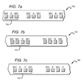
- FIGS. 7 a - c are top schematic views of portions of several light strips that may be used in fixtures according to embodiments of the present invention.
- FIG. 8 is a side perspective view of a lighting fixture according to embodiments of the present invention.
- FIG. 9 is a side perspective view of a lighting fixture according to embodiments of the present invention.
- Embodiments of the present invention provide a direct lighting fixture that is well-suited for use with solid state light sources, such as LEDs, and particularly useful for lighting aisles in commercial and industrial environments.
- An elongated housing comprises several integral elements including a heat sink, opposing side reflectors, and a mount surface.
- a plurality of light sources is disposed on the mount surface.
- Each light source or cluster of sources has an optical element such as a lens over it to redirect a portion of the light emitted from the sources in a desired direction, for example, to collimate the light.
- Reflective elements are placed on both sides of each light source or cluster to redirect light that is initially emitted in a longitudinal direction.
- the fixture may comprise multiple elongated housings connected together and aligned in parallel along the longitudinal direction. The fixture may also be scalable.
- Embodiments of the present invention are described herein with reference to conversion materials, wavelength conversion materials, remote phosphors, phosphors, phosphor layers and related terms. The use of these terms should not be construed as limiting. It is understood that the use of the term remote phosphors, phosphor or phosphor layers is meant to encompass and be equally applicable to all wavelength conversion materials.
- the term “source” can be used to indicate a single light emitter or more than one light emitter functioning as a single source.
- the term may be used to describe a single blue LED, or it may be used to describe a red LED and a green LED in proximity emitting as a single source.
- the term “source” should not be construed as a limitation indicating either a single-element or a multi-element configuration unless clearly stated otherwise.
- color as used herein with reference to light is meant to describe light having a characteristic average wavelength; it is not meant to limit the light to a single wavelength.
- light of a particular color e.g., green, red, blue, yellow, etc.
- Embodiments of the invention are described herein with reference to cross-sectional view illustrations that are schematic illustrations. As such, the actual thickness of layers can be different, and variations from the shapes of the illustrations as a result, for example, of manufacturing techniques and/or tolerances are expected. Thus, the regions illustrated in the figures are schematic in nature and their shapes are not intended to illustrate the precise shape of a region of a device and are not intended to limit the scope of the invention.
- FIG. 1 is a perspective view of a lighting fixture 100 according to an embodiment of the present invention.
- An elongated housing 102 extends along a longitudinal direction (x-direction).
- the housing 102 includes two substructures 102 a , 102 b in which light sources can be disposed.
- Other embodiments may include additional substructures which can be permanently connected (e.g., as a part of a monolithic structure) or removably connected, providing scalability.
- the housing 102 measures 4 inches in length (i.e., along the longitudinal direction).
- the fixtures may be joined end-to-end to create longer fixtures if necessary. 4 inches is merely an exemplary length. Many other lengths for the base housing components are certainly possible.
- Each substructure 102 a , 102 b comprises a heat sink 104 to help dissipate heat generated by light sources (not shown in this view).
- Heat sink structures are known in the art and therefore only briefly discussed herein.
- a mount surface 106 is on the heat sink 104 on the interior side of the housing 102 .
- the mount surface 106 provides a planar surface on which the light sources may be disposed.
- the mount surface 106 is on and in good thermal contact with heat sink 104 to provide a thermal path from the light sources to the ambient environment.
- Each substructure 102 a , 102 b further comprises a pair of opposing side reflectors 108 that extend away from the heat sink 104 to create a tunnel-like interior cavity.
- the side reflectors 108 are positioned such that light emitted from the light sources is redirected out of the fixture as a coarse adjustment (i.e., reduction) in the width of the outgoing beam.
- Some embodiments may include and enclosed or enclosable space for containing a power supply and/or routing wires for end-to-end attachment.
- the two substructures 102 a , 102 b are connected along one of the edges of two adjacent side reflectors 108 and also with connector beam 110 .
- the connector beam 110 provides additional mechanical support and also a planar surface on which additional elements may be disposed such as a fan, wiring, or electronic components, for example.
- the housing 102 also comprises mount slots 112 between the heat sinks 104 .
- the slots 112 are designed to cooperate with an exterior structure either suspended from or attached to a ceiling.
- the housing 102 can be either surface mounted to the ceiling or hang mounted using chains and/or cords, for example. Many different exterior mount mechanisms may be used.
- the elongated housing 102 can be extruded from many different materials, with a suitable material being aluminum, for example. Other methods of fabrication are also possible, including die casting and molding. If a monolithic structure is used, the housing 102 may be formed from a thermally conductive material. In some embodiments, the interior surfaces of said side reflectors can be coated with a highly reflective material, such as a metal, for example.
- FIG. 2 is a perspective view of the fixture 100 from a bottom side angle.
- FIG. 3 is a perspective bottom side view of the fixture 100 .
- a plurality of light sources 114 is arranged on the mount surface 106 .
- the light sources 114 are only shown in one of the substructures 102 a , but it is understood that additional light sources may be similarly disposed in the other substructure 102 b as well.
- a plurality of optical elements 116 is on said mount surface 106 and over said light sources 114 .
- Each optical element 114 is over a single light source 114 ; however, in other embodiments there may be a cluster of light sources under a single optical element.
- the optical elements comprise collimating lenses as discussed in more detail herein.
- Reflective elements 118 are also disposed along the mount surface 106 on both longitudinal sides of the light sources 114 . These elements are designed to redirect light that is initially emitted from the sources 114 in the longitudinal direction down toward the open end of the fixture, concentrating the light output into the desired area (e.g., an aisle beneath the fixture).
- the reflective elements 118 may be constructed from any highly reflective material, such as aluminum, and should be shaped to efficiently redirect light emitted at low angles in the longitudinal direction.
- the reflective elements 118 may comprise a specularly reflective material.
- the reflective elements 118 may be mounted to the mount surface using, for example, screws or an adhesive.
- FIG. 3 is a bottom perspective view of the fixture 100 .
- the optical elements 116 are aligned along the mount surface 106 in the longitudinal direction.
- the optical elements 116 may be made of any light transmissive material depending on the desired refractive effect.
- the optical elements may be mounted separately, or they may be connected and mounted as a single piece.
- FIGS. 4 and 5 are side perspective views of the fixture 100 .
- the individual sources 114 are on a light strip 120 which is mounted to the mount surface 106 .
- Light strips are discussed in more detail herein. Light from the sources that is initially emitted at a low angle (i.e., into region I) with a substantial transverse (z-direction) component will be redirected by the side reflectors 108 in a downward direction, away from the mount surface 106 and into the room area. Light that is initially emitted at higher angles (i.e., into region II) with a substantial transverse component will be redirected by the optical elements 116 in a direction toward the open end of the housing 102 .
- the optical elements 116 Light that would have otherwise been emitted from the housing 102 as uncontrolled light is controlled, in this case collimated, by the optical elements 116 .
- Light that is emitted having a substantial longitudinal component will impinge on the reflective elements 118 and be redirected into the optical elements 116 and then down toward the open end of the housing 102 .
- the combined effect of the side reflectors 108 , the optical elements 116 , and the reflective elements 118 is a relatively collimated output beam that is confined in the longitudinal direction. Such a beam is desirable for lighting a narrow area beneath the fixture 100 , such as an aisle.
- FIG. 5 several rays are traced to illustrate how light emitted from the sources 114 at certain angles interacts with the various features of the fixture 100 .
- all the rays shown are emitted in the transverse direction.
- light rays L 1 , L 2 , L 3 emitted at low angles impinge on the side reflectors 108 and are redirected downward toward the open end of the housing 102 .
- Light rays H 1 , H 2 , H 3 emitted at higher angles interact with the optical element 116 and are also redirected downward as shown.
- Light ray L 3 represents light which will exit the housing 102 with the highest escape angle, defining the width of the beam. In this particular embodiment, the total beam width is significantly reduced due to the collimating effect of the optical elements 116 . It is understood that many different optical elements are possible to achieve a particular output beam profile.
- FIG. 6 is a cross-sectional view of a portion of the fixture 100 .
- the light sources 114 are on a light strip 120 that is mounted to the mount surface 106 .
- Each source 114 is under one of the optical elements 116 and in between the reflective elements 118 .
- Several light rays are modeled to show some exemplary light paths. For simplification all the rays shown are emitted in the longitudinal direction. Rays S 1 , S 2 emitted at lower angles are redirected by the reflective element 118 toward the optical element 116 . Rays R 1 , R 2 emitted at higher angles are redirected by the optical element 116 . However, all of the rays are collimated to some degree by the optical element 116 as they pass through, providing extra beam control. Many different optical elements and reflective elements may be used in combination to tailor the output beam profile.
- the mount surface 106 provides a substantially flat area on which one or more light sources can be mounted.
- the light source(s) will be pre-mounted on light strips, such as a printed circuit board (PCB).
- FIGS. 7 a - c show a top view of portions of several light strips 700 , 720 , 740 that may be used to mount multiple LEDs to the mount surface 106 .
- LEDs are used as the light sources in various embodiments described herein, it is understood that other light sources, such as laser diodes for example, may be substituted in as the light sources in other embodiments of the invention.
- Embodiments of the lighting fixtures disclosed herein may comprise one or more emitters producing the same color of light or different colors of light.
- a multicolor source is used to produce white light.
- Several colored light combinations will yield white light.
- CCT correlated color temperature
- Both blue and yellow light can be generated with a blue emitter by surrounding the emitter with phosphors that are optically responsive to the blue light. When excited, the phosphors emit yellow light which then combines with the blue light to make white. In this scheme, because the blue light is emitted in a narrow spectral range it is called saturated light. The yellow light is emitted in a much broader spectral range and, thus, is called unsaturated light.
- RGB schemes may also be used to generate various colors of light.
- an amber emitter is added for an RGBA combination.
- the previous combinations are exemplary; it is understood that many different color combinations may be used in embodiments of the present invention.
- Several color combinations are described in detail in patents to Van de Ven (U.S. Pat. Nos. 7,213,940 and 7,768,192; both also owned by Cree, Inc.) which are incorporated by reference herein.
- the light strips 700 , 720 , 740 each represent possible LED combinations that result in an output spectrum that can be mixed to generate white light.
- Each lighting strip can include the electronics and interconnections necessary to power the LEDs.
- the light strip comprises a PCB with the LEDs mounted and interconnected thereon.
- the light strip 700 includes clusters 702 of discrete LEDs, with each LED within the cluster 702 spaced a distance from the next LED, and each cluster 702 spaced a distance from the next cluster. If the LEDs within a cluster are spaced at too great distance from one another, the colors of the individual sources may become visible, causing unwanted color-striping. In some embodiments, an acceptable range of distances for separating consecutive LEDs within a cluster is not more than approximately 8 mm.
- the scheme shown in FIG. 7 a uses a series of clusters 702 having two blue-shifted-yellow LEDs (“BSY”) and a single red LED (“R”).
- BSY refers to a color created when blue LED light is wavelength-converted by a yellow phosphor. The resulting output is a yellow-green color that lies off the black body curve.
- BSY and red light when properly mixed, combine to yield light having a “warm white” appearance.
- the lighting strip 720 includes clusters 722 of discrete LEDs.
- the scheme shown in FIG. 7 b uses a series of clusters 722 having three BSY LEDs and a single red LED. This scheme will also yield a warm white output when sufficiently mixed.
- the lighting strip 740 includes clusters 742 of discrete LEDs.
- the scheme shown in FIG. 7 c uses a series of clusters 742 having two BSY LEDs and two red LEDs. This scheme will also yield a warm white output when sufficiently mixed.
- FIGS. 7 a - c The lighting schemes shown in FIGS. 7 a - c are meant to be exemplary. Thus, it is understood that many different LED combinations can be used in concert with known conversion techniques to generate a desired output light color.
- FIG. 8 is a side perspective view of a lighting fixture 800 according to an embodiment of the present invention.
- the fixture 800 is similar to the fixture 100 shown in FIG. 1 .
- an elongated housing 802 comprises three substructures 800 a , 800 b , 800 c .
- Other embodiments may contain more or fewer than three substructures.
- lighting fixtures disclosed herein are easily scalable to accommodate wider room areas.
- additional substructures can be added to the design and simply fabricated as part of a monolithic housing structure, such as by extrusion, for example.
- FIG. 9 is a side perspective view of a fixture 900 according to an embodiment of the present invention.
- An elongated housing 902 comprises substructures 902 a , 902 b that are removably connectable to each other.
- the substructure may be connectable using many different attachment mechanisms.
- One suitable attachment mechanism is a snap-fit structure in which one substructure 902 b has male components 904 that are designed to cooperate with female components 906 on the other substructure 902 a .
- the snap-fit structure is only one example of an attachment mechanism; many other attachment mechanisms may also be used. It is understood that additional substructures may be added in a similar manner such that the fixture 900 is easily scalable, providing a system that is customizable post-manufacture.
Abstract
Description
Claims (25)
Priority Applications (1)
| Application Number | Priority Date | Filing Date | Title |
|---|---|---|---|
| US13/453,942 US9488330B2 (en) | 2012-04-23 | 2012-04-23 | Direct aisle lighter |
Applications Claiming Priority (1)
| Application Number | Priority Date | Filing Date | Title |
|---|---|---|---|
| US13/453,942 US9488330B2 (en) | 2012-04-23 | 2012-04-23 | Direct aisle lighter |
Publications (2)
| Publication Number | Publication Date |
|---|---|
| US20130279159A1 US20130279159A1 (en) | 2013-10-24 |
| US9488330B2 true US9488330B2 (en) | 2016-11-08 |
Family
ID=49379950
Family Applications (1)
| Application Number | Title | Priority Date | Filing Date |
|---|---|---|---|
| US13/453,942 Active 2035-01-21 US9488330B2 (en) | 2012-04-23 | 2012-04-23 | Direct aisle lighter |
Country Status (1)
| Country | Link |
|---|---|
| US (1) | US9488330B2 (en) |
Cited By (4)
| Publication number | Priority date | Publication date | Assignee | Title |
|---|---|---|---|---|
| US20160084446A1 (en) * | 2014-09-23 | 2016-03-24 | Osram Sylvania Inc. | Tubular LED Lamp |
| USD895878S1 (en) | 2018-05-04 | 2020-09-08 | Abl Ip Holding Llc | Asymmetric linear optic |
| US10948162B2 (en) | 2018-05-04 | 2021-03-16 | Abl Ip Holding Llc | Optics for aisle lighting |
| USD927037S1 (en) | 2018-05-04 | 2021-08-03 | Abl Ip Holding Llc | Symmetric linear optic |
Families Citing this family (8)
| Publication number | Priority date | Publication date | Assignee | Title |
|---|---|---|---|---|
| US9366422B2 (en) * | 2012-03-22 | 2016-06-14 | Makersled Llc | Slotted heatsinks and systems and methods related thereto |
| US9052088B2 (en) * | 2013-09-20 | 2015-06-09 | Whelen Engineering Company, Inc. | Tuned composite optical arrangement for LED array |
| KR101592649B1 (en) * | 2013-12-24 | 2016-02-12 | 현대자동차주식회사 | Laser optical system for head lamp |
| WO2015179352A1 (en) | 2014-05-19 | 2015-11-26 | Whelen Engineering Company, Inc. | Warning light with tinted lens |
| TWI522657B (en) * | 2014-09-25 | 2016-02-21 | 錼創科技股份有限公司 | Light reflecting apparatus |
| US10139078B2 (en) | 2015-02-19 | 2018-11-27 | Whelen Engineering Company, Inc. | Compact optical assembly for LED light sources |
| US10208914B2 (en) | 2015-09-09 | 2019-02-19 | Whelen Engineering Company, Inc. | Reflector with concentric interrupted reflecting surfaces |
| EP3244124A1 (en) * | 2016-05-12 | 2017-11-15 | Philips Lighting Holding B.V. | Luminaire and surface covering arrangement |
Citations (20)
| Publication number | Priority date | Publication date | Assignee | Title |
|---|---|---|---|---|
| US5823663A (en) | 1996-10-21 | 1998-10-20 | National Service Industries, Inc. | Fluorescent troffer lighting fixture |
| US6210025B1 (en) | 1999-07-21 | 2001-04-03 | Nsi Enterprises, Inc. | Lensed troffer lighting fixture |
| EP1298383A2 (en) | 2001-09-28 | 2003-04-02 | Osram Sylvania Inc. | Replaceable led lamp capsule |
| US20040001344A1 (en) * | 2002-07-01 | 2004-01-01 | Accu-Sort Systems, Inc. | Integrating led illumination system for machine vision systems |
| US7049761B2 (en) | 2000-02-11 | 2006-05-23 | Altair Engineering, Inc. | Light tube and power supply circuit |
| US7213940B1 (en) | 2005-12-21 | 2007-05-08 | Led Lighting Fixtures, Inc. | Lighting device and lighting method |
| US20070115670A1 (en) | 2005-11-18 | 2007-05-24 | Roberts John K | Tiles for solid state lighting panels |
| EP1847762A2 (en) | 2006-04-19 | 2007-10-24 | FARO FABBRICA APPARECCHIATURE RAZIONALI ODONTOIATRICHE S.p.A. | Compact lighting device, in particular for use in a dental lamp |
| US20090225543A1 (en) | 2008-03-05 | 2009-09-10 | Cree, Inc. | Optical system for batwing distribution |
| US20090323334A1 (en) | 2008-06-25 | 2009-12-31 | Cree, Inc. | Solid state linear array modules for general illumination |
| US7712918B2 (en) | 2007-12-21 | 2010-05-11 | Altair Engineering , Inc. | Light distribution using a light emitting diode assembly |
| US7722220B2 (en) | 2006-05-05 | 2010-05-25 | Cree Led Lighting Solutions, Inc. | Lighting device |
| US7768192B2 (en) | 2005-12-21 | 2010-08-03 | Cree Led Lighting Solutions, Inc. | Lighting device and lighting method |
| US7815338B2 (en) | 2008-03-02 | 2010-10-19 | Altair Engineering, Inc. | LED lighting unit including elongated heat sink and elongated lens |
| JP2011018571A (en) | 2009-07-09 | 2011-01-27 | Panasonic Corp | Heating cooker |
| JP2011018572A (en) | 2009-07-09 | 2011-01-27 | Sumitomo Wiring Syst Ltd | Male terminal fitting |
| US20110199769A1 (en) | 2010-02-17 | 2011-08-18 | Eric Bretschneider | Lighting unit with heat-dissipating chimney |
| WO2011140353A2 (en) | 2010-05-05 | 2011-11-10 | Intellilight Corp. | Remote phosphor tape for lighting units |
| US8092049B2 (en) | 2008-04-04 | 2012-01-10 | Ruud Lighting, Inc. | LED light fixture |
| US20120051041A1 (en) * | 2010-08-31 | 2012-03-01 | Cree, Inc. | Troffer-Style Fixture |
-
2012
- 2012-04-23 US US13/453,942 patent/US9488330B2/en active Active
Patent Citations (23)
| Publication number | Priority date | Publication date | Assignee | Title |
|---|---|---|---|---|
| US5823663A (en) | 1996-10-21 | 1998-10-20 | National Service Industries, Inc. | Fluorescent troffer lighting fixture |
| US6210025B1 (en) | 1999-07-21 | 2001-04-03 | Nsi Enterprises, Inc. | Lensed troffer lighting fixture |
| US7510299B2 (en) | 2000-02-11 | 2009-03-31 | Altair Engineering, Inc. | LED lighting device for replacing fluorescent tubes |
| US7049761B2 (en) | 2000-02-11 | 2006-05-23 | Altair Engineering, Inc. | Light tube and power supply circuit |
| EP1298383A2 (en) | 2001-09-28 | 2003-04-02 | Osram Sylvania Inc. | Replaceable led lamp capsule |
| US20040001344A1 (en) * | 2002-07-01 | 2004-01-01 | Accu-Sort Systems, Inc. | Integrating led illumination system for machine vision systems |
| US20070115670A1 (en) | 2005-11-18 | 2007-05-24 | Roberts John K | Tiles for solid state lighting panels |
| US20070115671A1 (en) | 2005-11-18 | 2007-05-24 | Roberts John K | Solid state lighting units and methods of forming solid state lighting units |
| US7213940B1 (en) | 2005-12-21 | 2007-05-08 | Led Lighting Fixtures, Inc. | Lighting device and lighting method |
| US7768192B2 (en) | 2005-12-21 | 2010-08-03 | Cree Led Lighting Solutions, Inc. | Lighting device and lighting method |
| EP1847762A2 (en) | 2006-04-19 | 2007-10-24 | FARO FABBRICA APPARECCHIATURE RAZIONALI ODONTOIATRICHE S.p.A. | Compact lighting device, in particular for use in a dental lamp |
| US7722220B2 (en) | 2006-05-05 | 2010-05-25 | Cree Led Lighting Solutions, Inc. | Lighting device |
| US7712918B2 (en) | 2007-12-21 | 2010-05-11 | Altair Engineering , Inc. | Light distribution using a light emitting diode assembly |
| US7815338B2 (en) | 2008-03-02 | 2010-10-19 | Altair Engineering, Inc. | LED lighting unit including elongated heat sink and elongated lens |
| US20090225543A1 (en) | 2008-03-05 | 2009-09-10 | Cree, Inc. | Optical system for batwing distribution |
| US8092049B2 (en) | 2008-04-04 | 2012-01-10 | Ruud Lighting, Inc. | LED light fixture |
| US20090323334A1 (en) | 2008-06-25 | 2009-12-31 | Cree, Inc. | Solid state linear array modules for general illumination |
| JP2011018571A (en) | 2009-07-09 | 2011-01-27 | Panasonic Corp | Heating cooker |
| JP2011018572A (en) | 2009-07-09 | 2011-01-27 | Sumitomo Wiring Syst Ltd | Male terminal fitting |
| US20110199769A1 (en) | 2010-02-17 | 2011-08-18 | Eric Bretschneider | Lighting unit with heat-dissipating chimney |
| US20110199005A1 (en) | 2010-02-17 | 2011-08-18 | Eric Bretschneider | Lighting unit having lighting strips with light emitting elements and a remote luminescent material |
| WO2011140353A2 (en) | 2010-05-05 | 2011-11-10 | Intellilight Corp. | Remote phosphor tape for lighting units |
| US20120051041A1 (en) * | 2010-08-31 | 2012-03-01 | Cree, Inc. | Troffer-Style Fixture |
Non-Patent Citations (8)
| Title |
|---|
| Cree's XLamp XP-E LED's, data sheet, pp. 1-16. |
| Cree's XLamp XP-G LED's, data sheet. pp. 1-12. |
| International Search Report and Written Opinion for Patent Application No. PCT/US2011/001517, dated: Feb. 27, 2012. |
| Office Action from Japanese Design Patent Application No. 2011-18570. |
| Reason for Rejection from Japanese Design Patent Application No. 2011-18571. |
| Reason for Rejection from Japanese Design Patent Application No. 2011-18572. |
| U.S. Appl. No. 12/873.303, filed Aug. 31, 2010 to Edmond, et al. |
| U.S. Appl. No. 12/961,385, filed Dec. 6, 2010 to Pickard, et al. |
Cited By (5)
| Publication number | Priority date | Publication date | Assignee | Title |
|---|---|---|---|---|
| US20160084446A1 (en) * | 2014-09-23 | 2016-03-24 | Osram Sylvania Inc. | Tubular LED Lamp |
| USD895878S1 (en) | 2018-05-04 | 2020-09-08 | Abl Ip Holding Llc | Asymmetric linear optic |
| US10948162B2 (en) | 2018-05-04 | 2021-03-16 | Abl Ip Holding Llc | Optics for aisle lighting |
| USD927037S1 (en) | 2018-05-04 | 2021-08-03 | Abl Ip Holding Llc | Symmetric linear optic |
| US11512834B2 (en) | 2018-05-04 | 2022-11-29 | Abl Ip Holding Llc | Optics for aisle lighting |
Also Published As
| Publication number | Publication date |
|---|---|
| US20130279159A1 (en) | 2013-10-24 |
Similar Documents
| Publication | Publication Date | Title |
|---|---|---|
| US11306895B2 (en) | Troffer-style fixture | |
| US11209135B2 (en) | Modular indirect suspended/ceiling mount fixture | |
| US9488330B2 (en) | Direct aisle lighter | |
| US8905575B2 (en) | Troffer-style lighting fixture with specular reflector | |
| US9494293B2 (en) | Troffer-style optical assembly | |
| US10323824B1 (en) | LED light fixture with light shaping features | |
| US9494294B2 (en) | Modular indirect troffer | |
| US10584860B2 (en) | Linear light fixture with interchangeable light engine unit | |
| US9366410B2 (en) | Reverse total internal reflection features in linear profile for lighting applications | |
| US9874333B2 (en) | Surface ambient wrap light fixture | |
| US8870417B2 (en) | Semi-indirect aisle lighting fixture | |
| US8764224B2 (en) | Luminaire with distributed LED sources | |
| US9581312B2 (en) | LED light fixtures having elongated prismatic lenses | |
| US20150252982A1 (en) | Standardized troffer fixture | |
| US9423104B2 (en) | Linear solid state lighting fixture with asymmetric light distribution | |
| US10612747B2 (en) | Linear shelf light fixture with gap filler elements | |
| US9285099B2 (en) | Parabolic troffer-style light fixture |
Legal Events
| Date | Code | Title | Description |
|---|---|---|---|
| AS | Assignment |
Owner name: CREE, INC., NORTH CAROLINA Free format text: ASSIGNMENT OF ASSIGNORS INTEREST;ASSIGNORS:PICKARD, PAUL KENNETH;RODGERS, ELIZABETH;O'FLAHERTY, PATRICK;SIGNING DATES FROM 20120801 TO 20121219;REEL/FRAME:029513/0126 |
|
| STCF | Information on status: patent grant |
Free format text: PATENTED CASE |
|
| AS | Assignment |
Owner name: IDEAL INDUSTRIES, LLC, ILLINOIS Free format text: ASSIGNMENT OF ASSIGNORS INTEREST;ASSIGNOR:CREE, INC.;REEL/FRAME:049285/0753 Effective date: 20190513 |
|
| AS | Assignment |
Owner name: IDEAL INDUSTRIES LIGHTING LLC, ILLINOIS Free format text: CORRECTIVE ASSIGNMENT TO CORRECT THE TYPOGRAPHICAL ERROR IN RECEIVING PARTY DATA FROM IDEAL INDUSTRIES, LLC TO IDEAL INDUSTRIES LIGHTING LLC PREVIOUSLY RECORDED ON REEL 049285 FRAME 0753. ASSIGNOR(S) HEREBY CONFIRMS THE ASSIGNMENT;ASSIGNOR:CREE, INC.;REEL/FRAME:051209/0001 Effective date: 20190513 |
|
| MAFP | Maintenance fee payment |
Free format text: PAYMENT OF MAINTENANCE FEE, 4TH YEAR, LARGE ENTITY (ORIGINAL EVENT CODE: M1551); ENTITY STATUS OF PATENT OWNER: LARGE ENTITY Year of fee payment: 4 |
|
| AS | Assignment |
Owner name: FGI WORLDWIDE LLC, NEW YORK Free format text: SECURITY INTEREST;ASSIGNOR:IDEAL INDUSTRIES LIGHTING LLC;REEL/FRAME:064897/0413 Effective date: 20230908 |