US9358329B2 - Catheter pump - Google Patents
Catheter pump Download PDFInfo
- Publication number
- US9358329B2 US9358329B2 US13/801,528 US201313801528A US9358329B2 US 9358329 B2 US9358329 B2 US 9358329B2 US 201313801528 A US201313801528 A US 201313801528A US 9358329 B2 US9358329 B2 US 9358329B2
- Authority
- US
- United States
- Prior art keywords
- circumferential
- distal
- cannula
- proximal
- connectors
- Prior art date
- Legal status (The legal status is an assumption and is not a legal conclusion. Google has not performed a legal analysis and makes no representation as to the accuracy of the status listed.)
- Active, expires
Links
- 239000000463 material Substances 0.000 claims description 19
- 210000004369 blood Anatomy 0.000 claims description 16
- 239000008280 blood Substances 0.000 claims description 16
- 238000005086 pumping Methods 0.000 claims description 7
- 238000000926 separation method Methods 0.000 claims description 6
- 229920002635 polyurethane Polymers 0.000 claims 1
- 239000004814 polyurethane Substances 0.000 claims 1
- 208000010392 Bone Fractures Diseases 0.000 description 18
- 206010017076 Fracture Diseases 0.000 description 18
- 238000000034 method Methods 0.000 description 15
- 230000008901 benefit Effects 0.000 description 11
- 230000001965 increasing effect Effects 0.000 description 11
- 239000002861 polymer material Substances 0.000 description 9
- 230000007704 transition Effects 0.000 description 9
- 239000011248 coating agent Substances 0.000 description 7
- 238000000576 coating method Methods 0.000 description 7
- 229920000642 polymer Polymers 0.000 description 7
- 238000013459 approach Methods 0.000 description 6
- 239000012530 fluid Substances 0.000 description 6
- 230000017531 blood circulation Effects 0.000 description 5
- 230000000747 cardiac effect Effects 0.000 description 5
- 230000006835 compression Effects 0.000 description 4
- 238000007906 compression Methods 0.000 description 4
- 238000013461 design Methods 0.000 description 4
- 230000001939 inductive effect Effects 0.000 description 4
- 238000012986 modification Methods 0.000 description 4
- 230000004048 modification Effects 0.000 description 4
- 230000004323 axial length Effects 0.000 description 3
- 230000006378 damage Effects 0.000 description 3
- 239000002184 metal Substances 0.000 description 3
- 208000010125 myocardial infarction Diseases 0.000 description 3
- 230000002829 reductive effect Effects 0.000 description 3
- 230000002861 ventricular Effects 0.000 description 3
- 206010018910 Haemolysis Diseases 0.000 description 2
- 206010019280 Heart failures Diseases 0.000 description 2
- 210000002376 aorta thoracic Anatomy 0.000 description 2
- 238000000418 atomic force spectrum Methods 0.000 description 2
- 230000009286 beneficial effect Effects 0.000 description 2
- 206010007625 cardiogenic shock Diseases 0.000 description 2
- 230000003247 decreasing effect Effects 0.000 description 2
- 210000005003 heart tissue Anatomy 0.000 description 2
- 230000008588 hemolysis Effects 0.000 description 2
- 238000011065 in-situ storage Methods 0.000 description 2
- 238000003780 insertion Methods 0.000 description 2
- 230000037431 insertion Effects 0.000 description 2
- 210000005240 left ventricle Anatomy 0.000 description 2
- HLXZNVUGXRDIFK-UHFFFAOYSA-N nickel titanium Chemical compound [Ti].[Ti].[Ti].[Ti].[Ti].[Ti].[Ti].[Ti].[Ti].[Ti].[Ti].[Ni].[Ni].[Ni].[Ni].[Ni].[Ni].[Ni].[Ni].[Ni].[Ni].[Ni].[Ni].[Ni].[Ni] HLXZNVUGXRDIFK-UHFFFAOYSA-N 0.000 description 2
- 229910001000 nickel titanium Inorganic materials 0.000 description 2
- 206010007556 Cardiac failure acute Diseases 0.000 description 1
- 210000003484 anatomy Anatomy 0.000 description 1
- 210000000709 aorta Anatomy 0.000 description 1
- 210000001765 aortic valve Anatomy 0.000 description 1
- 229920000249 biocompatible polymer Polymers 0.000 description 1
- 210000000601 blood cell Anatomy 0.000 description 1
- 210000004204 blood vessel Anatomy 0.000 description 1
- 230000008859 change Effects 0.000 description 1
- 238000010276 construction Methods 0.000 description 1
- 230000007423 decrease Effects 0.000 description 1
- 238000003618 dip coating Methods 0.000 description 1
- 238000006073 displacement reaction Methods 0.000 description 1
- 229940079593 drug Drugs 0.000 description 1
- 239000003814 drug Substances 0.000 description 1
- 230000009977 dual effect Effects 0.000 description 1
- 230000000694 effects Effects 0.000 description 1
- 229940124645 emergency medicine Drugs 0.000 description 1
- 230000002708 enhancing effect Effects 0.000 description 1
- 210000003743 erythrocyte Anatomy 0.000 description 1
- 210000001105 femoral artery Anatomy 0.000 description 1
- 230000005802 health problem Effects 0.000 description 1
- 208000019622 heart disease Diseases 0.000 description 1
- 210000003709 heart valve Anatomy 0.000 description 1
- 238000009998 heat setting Methods 0.000 description 1
- 238000010348 incorporation Methods 0.000 description 1
- 238000001802 infusion Methods 0.000 description 1
- 230000002401 inhibitory effect Effects 0.000 description 1
- 230000003993 interaction Effects 0.000 description 1
- 230000007794 irritation Effects 0.000 description 1
- 230000013011 mating Effects 0.000 description 1
- 238000000465 moulding Methods 0.000 description 1
- 210000004165 myocardium Anatomy 0.000 description 1
- 238000012856 packing Methods 0.000 description 1
- 238000013146 percutaneous coronary intervention Methods 0.000 description 1
- 230000001681 protective effect Effects 0.000 description 1
- 210000001147 pulmonary artery Anatomy 0.000 description 1
- 210000005241 right ventricle Anatomy 0.000 description 1
- 238000007493 shaping process Methods 0.000 description 1
- 238000010008 shearing Methods 0.000 description 1
- 238000004904 shortening Methods 0.000 description 1
- 238000009987 spinning Methods 0.000 description 1
- 230000007480 spreading Effects 0.000 description 1
- 238000012360 testing method Methods 0.000 description 1
- 210000001519 tissue Anatomy 0.000 description 1
- 230000001131 transforming effect Effects 0.000 description 1
Images


Classifications
-
- A—HUMAN NECESSITIES
- A61—MEDICAL OR VETERINARY SCIENCE; HYGIENE
- A61M—DEVICES FOR INTRODUCING MEDIA INTO, OR ONTO, THE BODY; DEVICES FOR TRANSDUCING BODY MEDIA OR FOR TAKING MEDIA FROM THE BODY; DEVICES FOR PRODUCING OR ENDING SLEEP OR STUPOR
- A61M60/00—Blood pumps; Devices for mechanical circulatory actuation; Balloon pumps for circulatory assistance
- A61M60/80—Constructional details other than related to driving
- A61M60/855—Constructional details other than related to driving of implantable pumps or pumping devices
- A61M60/857—Implantable blood tubes
-
- A61M1/101—
-
- A61M1/1008—
-
- A—HUMAN NECESSITIES
- A61—MEDICAL OR VETERINARY SCIENCE; HYGIENE
- A61M—DEVICES FOR INTRODUCING MEDIA INTO, OR ONTO, THE BODY; DEVICES FOR TRANSDUCING BODY MEDIA OR FOR TAKING MEDIA FROM THE BODY; DEVICES FOR PRODUCING OR ENDING SLEEP OR STUPOR
- A61M60/00—Blood pumps; Devices for mechanical circulatory actuation; Balloon pumps for circulatory assistance
- A61M60/10—Location thereof with respect to the patient's body
- A61M60/122—Implantable pumps or pumping devices, i.e. the blood being pumped inside the patient's body
- A61M60/126—Implantable pumps or pumping devices, i.e. the blood being pumped inside the patient's body implantable via, into, inside, in line, branching on, or around a blood vessel
- A61M60/13—Implantable pumps or pumping devices, i.e. the blood being pumped inside the patient's body implantable via, into, inside, in line, branching on, or around a blood vessel by means of a catheter allowing explantation, e.g. catheter pumps temporarily introduced via the vascular system
-
- A—HUMAN NECESSITIES
- A61—MEDICAL OR VETERINARY SCIENCE; HYGIENE
- A61M—DEVICES FOR INTRODUCING MEDIA INTO, OR ONTO, THE BODY; DEVICES FOR TRANSDUCING BODY MEDIA OR FOR TAKING MEDIA FROM THE BODY; DEVICES FOR PRODUCING OR ENDING SLEEP OR STUPOR
- A61M60/00—Blood pumps; Devices for mechanical circulatory actuation; Balloon pumps for circulatory assistance
- A61M60/10—Location thereof with respect to the patient's body
- A61M60/122—Implantable pumps or pumping devices, i.e. the blood being pumped inside the patient's body
- A61M60/165—Implantable pumps or pumping devices, i.e. the blood being pumped inside the patient's body implantable in, on, or around the heart
- A61M60/17—Implantable pumps or pumping devices, i.e. the blood being pumped inside the patient's body implantable in, on, or around the heart inside a ventricle, e.g. intraventricular balloon pumps
- A61M60/174—Implantable pumps or pumping devices, i.e. the blood being pumped inside the patient's body implantable in, on, or around the heart inside a ventricle, e.g. intraventricular balloon pumps discharging the blood to the ventricle or arterial system via a cannula internal to the ventricle or arterial system
-
- A—HUMAN NECESSITIES
- A61—MEDICAL OR VETERINARY SCIENCE; HYGIENE
- A61M—DEVICES FOR INTRODUCING MEDIA INTO, OR ONTO, THE BODY; DEVICES FOR TRANSDUCING BODY MEDIA OR FOR TAKING MEDIA FROM THE BODY; DEVICES FOR PRODUCING OR ENDING SLEEP OR STUPOR
- A61M60/00—Blood pumps; Devices for mechanical circulatory actuation; Balloon pumps for circulatory assistance
- A61M60/20—Type thereof
- A61M60/205—Non-positive displacement blood pumps
- A61M60/216—Non-positive displacement blood pumps including a rotating member acting on the blood, e.g. impeller
- A61M60/237—Non-positive displacement blood pumps including a rotating member acting on the blood, e.g. impeller the blood flow through the rotating member having mainly axial components, e.g. axial flow pumps
-
- A—HUMAN NECESSITIES
- A61—MEDICAL OR VETERINARY SCIENCE; HYGIENE
- A61M—DEVICES FOR INTRODUCING MEDIA INTO, OR ONTO, THE BODY; DEVICES FOR TRANSDUCING BODY MEDIA OR FOR TAKING MEDIA FROM THE BODY; DEVICES FOR PRODUCING OR ENDING SLEEP OR STUPOR
- A61M60/00—Blood pumps; Devices for mechanical circulatory actuation; Balloon pumps for circulatory assistance
- A61M60/40—Details relating to driving
- A61M60/403—Details relating to driving for non-positive displacement blood pumps
- A61M60/408—Details relating to driving for non-positive displacement blood pumps the force acting on the blood contacting member being mechanical, e.g. transmitted by a shaft or cable
- A61M60/411—Details relating to driving for non-positive displacement blood pumps the force acting on the blood contacting member being mechanical, e.g. transmitted by a shaft or cable generated by an electromotor
- A61M60/414—Details relating to driving for non-positive displacement blood pumps the force acting on the blood contacting member being mechanical, e.g. transmitted by a shaft or cable generated by an electromotor transmitted by a rotating cable, e.g. for blood pumps mounted on a catheter
-
- A—HUMAN NECESSITIES
- A61—MEDICAL OR VETERINARY SCIENCE; HYGIENE
- A61M—DEVICES FOR INTRODUCING MEDIA INTO, OR ONTO, THE BODY; DEVICES FOR TRANSDUCING BODY MEDIA OR FOR TAKING MEDIA FROM THE BODY; DEVICES FOR PRODUCING OR ENDING SLEEP OR STUPOR
- A61M60/00—Blood pumps; Devices for mechanical circulatory actuation; Balloon pumps for circulatory assistance
- A61M60/50—Details relating to control
- A61M60/508—Electronic control means, e.g. for feedback regulation
-
- A—HUMAN NECESSITIES
- A61—MEDICAL OR VETERINARY SCIENCE; HYGIENE
- A61M—DEVICES FOR INTRODUCING MEDIA INTO, OR ONTO, THE BODY; DEVICES FOR TRANSDUCING BODY MEDIA OR FOR TAKING MEDIA FROM THE BODY; DEVICES FOR PRODUCING OR ENDING SLEEP OR STUPOR
- A61M60/00—Blood pumps; Devices for mechanical circulatory actuation; Balloon pumps for circulatory assistance
- A61M60/80—Constructional details other than related to driving
- A61M60/802—Constructional details other than related to driving of non-positive displacement blood pumps
- A61M60/804—Impellers
- A61M60/806—Vanes or blades
- A61M60/808—Vanes or blades specially adapted for deformable impellers, e.g. expandable impellers
-
- A—HUMAN NECESSITIES
- A61—MEDICAL OR VETERINARY SCIENCE; HYGIENE
- A61M—DEVICES FOR INTRODUCING MEDIA INTO, OR ONTO, THE BODY; DEVICES FOR TRANSDUCING BODY MEDIA OR FOR TAKING MEDIA FROM THE BODY; DEVICES FOR PRODUCING OR ENDING SLEEP OR STUPOR
- A61M60/00—Blood pumps; Devices for mechanical circulatory actuation; Balloon pumps for circulatory assistance
- A61M60/80—Constructional details other than related to driving
- A61M60/802—Constructional details other than related to driving of non-positive displacement blood pumps
- A61M60/81—Pump housings
-
- A—HUMAN NECESSITIES
- A61—MEDICAL OR VETERINARY SCIENCE; HYGIENE
- A61M—DEVICES FOR INTRODUCING MEDIA INTO, OR ONTO, THE BODY; DEVICES FOR TRANSDUCING BODY MEDIA OR FOR TAKING MEDIA FROM THE BODY; DEVICES FOR PRODUCING OR ENDING SLEEP OR STUPOR
- A61M60/00—Blood pumps; Devices for mechanical circulatory actuation; Balloon pumps for circulatory assistance
- A61M60/80—Constructional details other than related to driving
- A61M60/802—Constructional details other than related to driving of non-positive displacement blood pumps
- A61M60/818—Bearings
- A61M60/825—Contact bearings, e.g. ball-and-cup or pivot bearings
-
- A—HUMAN NECESSITIES
- A61—MEDICAL OR VETERINARY SCIENCE; HYGIENE
- A61M—DEVICES FOR INTRODUCING MEDIA INTO, OR ONTO, THE BODY; DEVICES FOR TRANSDUCING BODY MEDIA OR FOR TAKING MEDIA FROM THE BODY; DEVICES FOR PRODUCING OR ENDING SLEEP OR STUPOR
- A61M60/00—Blood pumps; Devices for mechanical circulatory actuation; Balloon pumps for circulatory assistance
- A61M60/80—Constructional details other than related to driving
- A61M60/855—Constructional details other than related to driving of implantable pumps or pumping devices
- A61M60/857—Implantable blood tubes
- A61M60/859—Connections therefor
-
- A61M1/10—
-
- A61M1/12—
-
- A61M1/122—
-
- A—HUMAN NECESSITIES
- A61—MEDICAL OR VETERINARY SCIENCE; HYGIENE
- A61M—DEVICES FOR INTRODUCING MEDIA INTO, OR ONTO, THE BODY; DEVICES FOR TRANSDUCING BODY MEDIA OR FOR TAKING MEDIA FROM THE BODY; DEVICES FOR PRODUCING OR ENDING SLEEP OR STUPOR
- A61M60/00—Blood pumps; Devices for mechanical circulatory actuation; Balloon pumps for circulatory assistance
- A61M60/10—Location thereof with respect to the patient's body
- A61M60/122—Implantable pumps or pumping devices, i.e. the blood being pumped inside the patient's body
- A61M60/126—Implantable pumps or pumping devices, i.e. the blood being pumped inside the patient's body implantable via, into, inside, in line, branching on, or around a blood vessel
- A61M60/148—Implantable pumps or pumping devices, i.e. the blood being pumped inside the patient's body implantable via, into, inside, in line, branching on, or around a blood vessel in line with a blood vessel using resection or like techniques, e.g. permanent endovascular heart assist devices
Definitions
- This application is directed to a catheter pump for mechanical circulatory support of a heart.
- Heart disease is a major health problem that has high mortality rate. After a heart attack, only a small number of patients can be treated with medicines or other non-invasive treatment. However, a significant number of patients can recover from a heart attack or cardiogenic shock if provided with mechanical circulatory support.
- a blood pump having a fixed cross-section is surgically inserted between the left ventricle and the aortic arch to assist the pumping function of the heart.
- Other known applications involve providing for pumping venous blood from the right ventricle to the pulmonary artery for support of the right side of the heart.
- the object of the surgically inserted pump is to reduce the load on the heart muscle for a period of time, to stabilize the patient prior to heart transplant or for continuing support. Surgical insertion, however, can cause additional serious stresses in heart failure patients.
- LVAD left ventricular assist device
- RVAD right ventricular assist device
- biVAD a system for both sides of the heart
- the cannula should have sufficient force to expand, but also be collapsible under significant sheathing force while avoiding a risk of damaging the cannula during re-sheathing.
- improved cannula that can be expanded and collapsed, in some cases over many cycles, without risking breakage of the struts and connectors forming the mesh. Broken struts pose a risk of complicating patient treatment and/or compromising the performance of the device.
- an apparatus for inducing motion of a fluid relative to the apparatus.
- the apparatus can be a catheter pump, as discussed below.
- the apparatus can include a rotatable impeller and an elongate cannula.
- the cannula has a plurality of circumferential members and a plurality of circumferential connectors.
- the circumferential members are disposed about a space, e.g., a volume including at least the impeller zone.
- One or more of, e.g., each of, the circumferential members can have an undulating configuration including a plurality of apices connected by elongate struts.
- the circumferential connectors can be disposed between alternating struts of adjacent circumferential members.
- a plurality of axial connectors is disposed between a proximal side of a proximal apex and a distal side of an adjacent circumferential member in the impeller zone of cannula.
- the cannula is differentiated along its length to have varying stiffness.
- the elongate cannula has an impeller zone disposed about the impeller and a distal zone disposed distal of the impeller zone.
- the distal zone can be made more flexible by reducing the number of connectors disposed therein.
- the impeller zone can have alternating elongate struts that are connected by circumferential connectors and the distal zone can have alternating elongate struts that are free of such connections.
- each of the connectors of the plurality has a distal end coupled with a proximal side of a proximal apex of a first circumferential member, a proximal end coupled with a distal face of a second circumferential member disposed adjacent to and proximal of the first circumferential member.
- Each of the connectors has an arcuate section disposed between the proximal and distal ends. In this variation, the arcuate section comprises a single convex portion disposed between the proximal and distal ends.
- a first plurality of axial connectors is disposed between a proximal side of a proximal apex and a distal side of an adjacent circumferential member in the impeller zone of the cannula.
- a second plurality of axial connectors is disposed between a proximal side of a proximal apex and a distal side of an adjacent circumferential member in the distal zone of the cannula.
- an apparatus for pumping blood in another embodiment, includes a rotatable impeller, an elongate cannula, and a sheath configured to be positioned over the elongate cannula.
- the elongate cannula has a plurality of circumferential members disposed about the impeller.
- One or more of, e.g., each of, the circumferential members can have an undulating configuration.
- the undulating configuration can include a plurality of proximal and distal apices, with proximal apices connected to distal apices by an elongate strut.
- the sheath is configured to be positioned over the elongate cannula to actuate the cannula from an expanded configuration to a collapsed configuration.
- the elongate cannula is configured to deflect radially inwardly in an area around the proximal apices before the apices move into the sheath.
- the elongate cannula has an impeller zone disposed about the impeller and a distal zone disposed distal of the impeller zone.
- the impeller can extend in about one-half or less of the length of the cannula.
- the distal zone may be more easily compressed by the sheath because the impeller is not present in that area.
- the cannula can have a different configuration in the distal zone.
- a catheter pump is provided.
- a catheter pump is an example of an apparatus for inducing motion of a fluid relative to the apparatus.
- the catheter pump includes a rotatable impeller and an elongate cannula having a mesh comprising a plurality of circumferential members disposed about the impeller.
- the mesh also has a plurality of axial connectors extending between a proximal side of a distal circumferential member and a distal side of a proximal circumferential member.
- the circumferential members are radially self-expandable.
- a sheath is configured to be positioned over the elongated cannula to actuate the cannula from an expanded configuration to a collapsed configuration.
- the cannula is configured to minimize a risk of fracture within the mesh, e.g., of the axial connectors, as the elongated cannula moves into the sheath.
- an apparatus for inducing motion of a fluid relative to the apparatus includes a a rotatable impeller and an elongate cannula.
- the elongate cannula is defines a blood flow channel in which the impeller is disposed.
- the cannula has an expandable structure comprising that has a plurality of circumferential members, a plurality of circumferential connectors, and a plurality of axial connectors.
- the circumferential members are disposed about the blood flow channel.
- the circumferential members have an undulating configuration including a plurality of apices connected by elongate struts.
- the circumferential connectors are disposed between alternating struts of adjacent circumferential members.
- the axial connectors have a distal end coupled with a proximal side of a proximal apex of a first circumferential member, a proximal end coupled with a distal face (e.g., an edge) of a second circumferential member disposed adjacent to and proximal of the first circumferential member.
- the axial connectors have an arcuate section disposed between the proximal and distal ends.
- the arcuate section comprises a single convex portion disposed between the proximal and distal ends.
- an apparatus for pumping blood in another embodiment, includes a rotatable impeller, an elongate cannula, and an axial member.
- the elongate cannula has a plurality of circumferential members disposed about the impeller.
- One or more of the circumferential members has an undulating configuration including a plurality of proximal and distal apices. Each proximal apex is connected to a distal apex by an elongate strut.
- the axial member has a distal end coupled with a proximal apex of a first circumferential member a proximal end coupled with a second circumferential member disposed proximal of the first circumferential member.
- the axial member has a length that is less than the distance between the proximal apex to which the distal end of the axial member is connected and a proximal apex of the second circumferential member that is axially aligned with the proximal apex to which the distal end of the axial member is connected.
- a catheter pump in another embodiment, includes a rotatable impeller and an elongate cannula.
- the elongate cannula has a mesh that has a plurality of circumferential members disposed about the impeller.
- the elongate cannula has a plurality of axial connector extending between a proximal side of a distal circumferential member and a distal side of a proximal circumferential member.
- the circumferential members are radially self-expandable.
- the cannula is configured to minimize fracture within at least in the distal zone of the mesh as the elongated cannula moves into a sheathing device.
- a cannula for conveying blood in another embodiment, includes an in-situ expandable and collapsible mesh structure and a polymeric enclosure.
- the in-situ expandable and collapsible mesh structure has a plurality of undulating circumferential members surrounding a lumen. Each circumferential member has proximal and distal vertices.
- the polymeric enclosure is disposed about the mesh structure to enclose the lumen along a length between an inlet and an outlet.
- the number of proximal vertices in an area defined between a proximal circumference intersecting the proximal vertex of a circumferential member and a distal circumference intersecting the distal vertex of the same circumferential member adjacent to the proximal vertex is at least two.
- FIG. 1 illustrates one embodiment of a catheter pump configured for percutaneous application and operation
- FIG. 2 is a plan view of one embodiment of a catheter assembly adapted to be used with the catheter pump of FIG. 1 ;
- FIG. 3 show a distal portion of the catheter assembly of similar to that of FIG. 2 in position within the anatomy;
- FIG. 4 illustrates a wall pattern of a mesh structure in a flat configuration, where the mesh structure is configured to provide enhanced flexibility in a distal zone;
- FIG. 4A is a detail view of a distal portion of the wall pattern of FIG. 4 ;
- FIG. 5 shows a formed mesh structure for a cannula having a wall pattern similar to that of FIG. 4 ;
- FIG. 5A is a detail view of the distal portion of the formed mesh structure of FIG. 5 ;
- FIG. 6 illustrates another wall pattern of a mesh structure in a flat configuration, where the mesh structure is configured to minimize fracture risk
- FIG. 6A is a detail view of a distal portion of the wall pattern of FIG. 6 ;
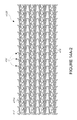
- FIG. 7 shows a cannula including a formed mesh structure having the wall pattern similar to that of FIG. 6 covered with a film layer;
- FIG. 7A is a detail view of a distal portion of the cannula of FIG. 7 ;
- FIG. 8 illustrates another wall pattern of a mesh structure in a flat configuration, where the mesh structure is configured to provide enhanced flexibility in a distal zone, while minimizing fracture risk;
- FIG. 9 shows a formed mesh structure for a cannula having the wall pattern of FIG. 8 ;
- FIG. 10 illustrates another wall pattern of a mesh structure in a flat configuration, where the mesh structure is configured to provide enhanced flexibility in a distal zone, while minimizing fracture risk;
- FIG. 11 shows a formed mesh structure for a cannula having the wall pattern of FIG. 10 ;
- FIG. 12 is a detail view of a distal portion of the wall pattern of FIGS. 8 and 10 ;
- FIG. 13 is a detail view of a first variation of the distal portion of the formed mesh structure of FIG. 12 ;
- FIG. 14 is a detail view of a second variation of the distal portion of the formed mesh structure of FIG. 12 ;
- FIG. 14A-1 is a detail view of a proximal portion of another variation of a wall pattern that is stable and minimizes fracture;
- FIG. 14A-2 is a detail view of a central portion of the wall pattern for which the proximal portion is shown in FIG. 14A-1
- FIG. 14A-3 is a detail view of a distal portion of the wall pattern for which the proximal portion is shown in FIG. 14A-1
- FIG. 15 illustrates another wall pattern of a mesh structure in a flat configuration, where the mesh structure is configured to provide more ports for blood to flow into or out of a cannula formed with this pattern;
- FIG. 15A is a detail view of a proximal portion of the pattern of FIG. 15 ;
- FIG. 16 is an expanded view of the pattern of FIGS. 15-15A ;
- FIG. 17 is a graph of the sheathing force for collapsing a cannula and an impeller for an example wall pattern.
- the apparatus can be a catheter pump, e.g., a percutaneous heart pump.
- FIGS. 1 and 2 illustrate various features of a catheter pump 10 .
- the catheter pump 10 can provide high performance including flow rates similar to full cardiac output.
- the pump 10 includes a motor driven by a controller 22 .
- the controller 22 directs the operation of the motor 14 and an infusion system 26 that supplies a flow of infusate in the pump 10 .
- a catheter system 80 that can be coupled with the motor 14 houses an impeller within a distal portion thereof.
- the impeller is rotated remotely by the motor 14 when the pump 10 is operating.
- the motor 14 can be disposed outside the patient.
- the motor 14 is separate from the controller 22 , e.g., to be placed closer to the patient.
- the motor 14 is part of the controller 22 .
- the motor is miniaturized to be insertable into the patient.
- Such embodiments allow the drive shaft to be much shorter, e.g., shorter than the distance from the aortic valve to the aortic arch (about 5 cm or less).
- FIG. 3 illustrates one use of the catheter pump 10 .
- a distal portion of the pump 10 is placed in the left ventricle LV of the heart to pump blood from the LV into the aorta.
- the pump 10 can be used in this way to treat patients with a wide range of conditions, including cardiogenic shock, myocardial infarction, and acutely decompensated heart failure, and also to support a patient during a procedure such as percutaneous coronary intervention.
- One convenient manner of placement of the distal portion of the pump 10 in the heart is by percutaneous access and delivery using the Seldinger technique or other methods familiar to cardiologists. These approaches enable the pump 10 to be used in emergency medicine, a catheter lab and in other non-surgical settings.
- Modifications can also enable the pump 10 to support the right side of the heart.
- Example modifications that could be used for right side support include providing delivery features and/or shaping a distal portion that is to be placed through at least one heart valve from the venous side, such as is discussed in U.S. Pat. Nos. 6,544,216; 7,070,555; and US 2012-0203056A1, all of which are hereby incorporated by reference herein in their entirety for all purposes.
- FIG. 2 shows features that facilitate small blood vessel percutaneous delivery and high performance up to and in some cases exceeding normal cardiac output in all phases of the cardiac cycle.
- the catheter system 80 includes a catheter body 84 and a sheath assembly 88 .
- An impeller assembly 92 is coupled with the distal end of the catheter body 84 .
- the impeller assembly 92 is expandable and collapsible. In the collapsed state, the distal end of the catheter system 80 can be advanced to the heart. In the expanded state the impeller assembly 92 is able to pump blood at relatively high flow rates.
- FIGS. 2 and 3 illustrate the expanded state.
- the collapsed state can be provided by advancing a distal end 94 of an elongate body 96 distally over the impeller assembly 92 to cause the impeller assembly 92 to collapse.
- This provides an outer profile throughout the catheter assembly 80 that is of small diameter, for example 12.5 French as discussed further below.
- Embodiments of the catheter pumps of this application can be configured with expandable structures to enhance performance.
- an impeller for moving blood axially can be provided.
- the impeller can be positioned in an expandable cannula.
- the expandable cannula provides dual function of enclosing a blood flow lumen through which the impeller can act and also housing the impeller.
- the cannula is also an expandable housing.
- the expandable cannula and impeller provide a flow rate in the pump that is much larger than would be possible using percutaneous access techniques were these components not capable of expanding.
- impeller may be sequentially collapse the impeller, e.g., by withdrawing the impeller into a rigid ring or tubular segment prior to collapsing the impeller.
- impeller may not be housed in the cannula at all times or at all.
- a mesh is used to support the expandable portion of a blood flow conduit in the impeller assembly 92 .
- the expandable portion can include a self-expanding structure that expands when undulating generally ring-shaped members release stored strain energy arising from circumferential compression. Compression of such a structure involves transforming axial relative movement of the sheath assembly 88 over the catheter body 84 into a circumferential compression force. There is a chance that such movement will cause the distal end to become lodged between adjacent undulating members.
- FIGS. 4-16 illustrate various embodiments of mesh structures that can be incorporated into the expandable cannula to provide advantageous performance in use.
- FIG. 4 shows a flat wall pattern 200 of a mesh structure 204 that is configured to provide enhanced flexibility in a distal zone 208 .
- the distal zone 208 is disposed distally of an impeller zone 212 , which is a portion of the mesh structure 204 that is disposed around an impeller in the catheter assembly of FIG. 2 .
- the impeller can be part of the impeller assembly 116 , as set forth in more detail in the U.S. application Ser. No. 13/343,617, incorporated by reference above.
- the distal zone 208 and the impeller zone 212 are distinct from each other, for example having separate structure or performance characteristics.
- the distal and impeller zones 208 , 212 are general regions of an otherwise continuous structure.
- the wall pattern 200 also includes distal and proximal end connection structures 216 A, 216 B, which are discussed in detail in the '617 application incorporated by reference above, and also in U.S. application Ser. No. 13/343,618, which is hereby incorporated by reference herein in it's entirety.
- the wall pattern 200 illustrates a plurality of circumferential members 224 and a plurality of circumferential connectors 228 .
- the circumferential members 224 can be seen to extend transversely to a longitudinal axis of the pattern 200 .
- these structures can be seen to extend about the circumference of the formed mesh structure 204 . As discussed below, e.g., in connection with FIGS.
- a cannula is formed by enclosing the circumferential members 224 with a polymer material, e.g., a film, to create a flow channel open on the ends but otherwise sealed to maximize axial flow through the cannula and the pump.
- a polymer material e.g., a film
- the circumferential members 224 and later the cannula are disposed about a space, e.g., a volume including at least the impeller zone 212 .
- the polymer material is a coating disposed about the cannula mesh structure 204 .
- Suitable materials for the polymer coating include, but are not limited to a biocompatible polymer, a drug-eluting polymer, and a functionalized polymer such as a thromboresistant material.
- the polymer material is HapflexTM or ThoralonTM.
- the polymer material fills the voids in the mesh structure.
- the polymer material also coats the inner and outer walls such that the mesh structure does not come into contact with blood and tissue.
- the polymer material is a thin coating.
- the polymer coating has a maximum thickness of less than 10 microns, less than 9 microns, less than 8 microns, less than 7 microns, less than 6 microns, less than 5 microns, less than 4 microns, less than 3 microns, less than 2 microns, or less than 1 micron.
- the polymer coating is formed of a plurality of layers.
- the polymer coating is configured to reinforce the mesh structure.
- the polymer material may be applied by dip coating, molding, spinning on a mandrel, or other techniques.
- the polymer coating may be configured and applied in various other manners. Further details of suitable materials are set forth in U.S. Pat. Nos. 4,675,361 and 6,939,377, which are incorporated by reference herein in their entireties and for all purposes.
- the circumferential members 224 preferably are configured to be self-expandable, also described as self-expanding herein.
- FIG. 4 shows that in one embodiment one or more of the circumferential members 224 can have an undulating configuration.
- circumferential members can have an alternating structure, e.g., a plurality proximal turns and distal turns connected by struts.
- the struts can be straight members that each have a proximal ends connected to a proximal turn and a distal end connected to a distal turn.
- the distal turns can be peaks and the proximal turns can be valleys, e.g., if the cannula is held with the distal end up.
- the distal turns can be crests and the proximal turns can be troughs, e.g., if the cannula is held with the distal end up.
- the circumferential members have a generally serpentine configuration, or can be sinusoidal in nature disposed on both sides of a transverse plane.
- the circumferential members 224 can include a plurality of distal and proximal apices 232 A, 232 B connected by elongate struts 236 . As discussed further below, the density of the circumferential members 224 can be varied to modify the performance or the cannula.
- the circumferential connectors 228 can be disposed between alternating struts 236 of adjacent circumferential members 224 in at least one of the distal and impeller zones 208 , 212 .
- the connectors 228 (or other connectors discussed herein) can join a node on one circumferential member to a node on an adjacent circumferential member.
- the nodes are offset from the peaks and valleys.
- At least one of the nodes can be disposed on a strut that extends between adjacent nodes.
- connectors are disposed between the crests and trough and can be disposed between a crest the a transverse mid-point of a sinusoidal circumferential member.
- the width of nodes are greater in the impeller zone than distal thereof.
- FIG. 4 shows that circumferential connector 228 can be provided between opposing sides of adjacent struts 236 of at least two adjacent circumferential members 224 in the impeller zone.
- alternating elongate struts 236 are connected to an adjacent elongate strut of an adjacent circumferential member 224 .
- alternating elongate struts 236 are not connected to adjacent elongate struts by circumferential connectors 228 .
- asymmetrical can refer to unequal movement upon expansion of the elongate struts 236 away from a central axis extending through an unexpanded apex.
- the central axis can be an axis intersecting an apex and being located equal distance from inner edges of unexpanded adjacent elongate struts 236 .
- FIG. 4 shows that while circumferential connectors 228 are provided in the impeller zone 212 , the connectors 228 can be omitted in the distal zone 208 .
- Such an arrangement provides enhanced rigidity of the impeller zone 212 compared to the distal zone 208 .
- FIGS. 6 and 14A-1 to 14A-3 are other embodiments in which circumferential connectors 228 are provide throughout a distal zone as well as in an impeller zone. More generally, the circumferential connectors 228 can be provided between opposing sides of alternating adjacent elongate struts of less than all of the circumferential members in the distal zone 208 , while still providing benefits as discussed below.
- a substantial portion such as one-half or more of the struts 236 can be connected by circumferential connectors 228 in the distal portion in one embodiment.
- the density of connectors 228 in the distal zone 208 can be about one-half or less that in the impeller zone 212 .
- two groups of circumferential connectors 228 A, 228 B can be provided.
- a first plurality connectors 228 A can be provided about the impeller zone 212 in which the connectors have a length along the struts 236 that the connectors 228 A join that is greater than the separation between adjacent circumferential members, e.g. between the struts 236 that they join.
- the length of the connectors 228 A along the struts 236 that they join is greater than the separation between adjacent circumferential members in the unexpanded state in some embodiments.
- a second plurality connectors 228 B can be provided between the impeller an distal zones 212 , 208 in which the connectors have a length along the struts 236 that they join that is less than the length of the connectors 228 A.
- the length of each of the connectors 228 B along the struts 236 to which they are coupled can be about one-half that of the first connectors 228 A.
- FIG. 4A shows details of a portion of the distal zone 208 .
- a plurality of axial connectors 252 can be provided between proximal side of a proximal apex and a distal side of an adjacent circumferential member in the distal zone of the cannula.
- the same connectors can be provided in the impeller zone 212 .
- FIG. 4 shows that in some embodiments a modified axial connector 252 A can be provided in the impeller zone 212 .
- the connectors 252 A have a first end that forms an apical connection with a proximally oriented apex 232 B and a second end.
- the second end is coupled in between adjacent apices of a circumferential member, e.g., along a side of an elongate strut 236 .
- the connectors 252 A can be connected to the struts 236 at the same location that the strut connects to an adjacent strut by way of the connector 228 A.
- the connectors 252 A are shortened compared to the connectors 252 . For example, they can extend with fewer undulations along their length, e.g., with a single inflection point between the ends.
- substantially all of the impeller zone 212 has enhanced rigidity connectors 252 A.
- FIG. 5 shows a transition zone that can be provided at one or both of the proximal and distal ends of the impeller zone 212 .
- a transition zone TZ-B can be provided to facilitate radial transition from the expanded size of the formed mesh to the diameter of a non-expanding portion 254 of the formed mesh that does not expand.
- a transition zone TZ-A between the impeller and distal zones can provide for more gradual change in mechanical characteristics to provide for gradual collapse of the cannula, as discussed below.
- FIG. 5 shows an expanded mesh structure 204 formed of the pattern 200 .
- the mesh structure 204 comprises a plurality of spaced apart helical zones 260 .
- the helical zones 260 are formed by adjacent struts 236 that have less or no movement relative to each other during expansion, where connectors 228 are provided. Adjacent struts that are connected by connectors 228 tend to move or expand less than struts that are not so connected, or do not move or expand at all.
- FIGS. 5 and 5A shows that the helical zones 260 are in the impeller zone 212 and not in the distal zone.
- the helical zones 260 provide enhanced concentration of material around the proximal apices 232 B of circumferential members 224 in the impeller zone 212 .
- Enhanced concentration of material provides enhanced local stiffness around the proximal apices 232 B, which provides greater stiffness and protects the proximal apices 232 B and connectors disposed thereon from fracture.
- proximal apices in a zone e.g., a distal zone
- the helical zones are induced to preserve this protective structure around the proximal apices.
- Such arrangements aid in the re-sheathing of a cannula incorporating this structure.
- Enhanced concentration of material makes the connection between the apices 232 B and adjacent proximal circumferential member 224 more robust.
- larger forces are encountered in the impeller zone 212 during collapsing of, sometimes referred to as re-sheathing of, the cannula, e.g., after the catheter pump has been used.
- FIG. 17 shows a graph of axial force that may be required to be applied to an outer sheath, such as by the sheath assembly 88 , disposed about the catheter body 120 (see FIG. 2 ) as the sheath assembly is advanced distally along the cannula.
- This figure shows that in region A the force is relatively high when the distal end of the sheath initially engages the proximal end of the expanded zone of the cannula.
- the force also increases in a region B to a relatively high level when the distal end of the outer sheath is advanced to a location over the proximal end of the impeller.
- the robustness can be enhanced in any one or all of a variety of ways, such as shortening axially oriented connectors between adjacent circumferential members, increasing material per unit area in a region around proximally oriented apices, providing an expanded configuration in which struts of the mesh are positioned close together around a weak point in the mesh structure, and other ways described herein.
- FIGS. 4-5A and other embodiments herein illustrate some specific ways of improving the reliability of an expandable cannula, which can help to minimize the risk of breakage within the mesh, e.g., breakage of the connectors 252 A.
- a first technique is making the connectors 252 A shorter than the connectors 252 .
- a second technique involves the enhanced concentration of material around the proximal apices 232 B, discussed above.
- the distal zone 208 is substantially free of the helical zones 260 or other concentration of material in the embodiment of FIG. 4-5A .
- the struts 236 expand substantially symmetrically about the apices 232 A forming a more uniform expanded mesh in the distal zone 208 .
- This arrangement enhances the overall flexibility of the distal zone 208 , which can be beneficial.
- this arrangement makes local zones of the expanded mesh structure 204 substantially uniformly flexible.
- a mesh structure 204 with a more flexible distal zone 208 , and more uniform flexibility, can provide a cannula with a reduced risk of irritating the inner structures of the heart when deployed.
- FIG. 6 shows an embodiment, in which the distal zone 208 is modified to minimize a risk of fracturing connectors in the distal zone.
- a first plurality of axial connectors 272 is disposed between a proximal side of a proximal apex 232 B and a distal side of an adjacent circumferential member 224 in the impeller zone 212 .
- FIG. 6A shows a second plurality of axial connectors 272 A is disposed between a proximal side of a proximal apex 232 B and a distal side of an adjacent circumferential member 224 in the distal zone 208 of the cannula.
- connectors 272 A are provided between proximal apices 232 B and a middle portion of the elongate members 236 .
- the axial connectors 272 A of the second plurality have first and second ends, and a singe curved section therebetween.
- the axial connectors 272 of the first plurality have first and second ends, and a plurality of curved section therebetween.
- the axial connectors 272 have multiple undulations and the connectors 272 A have a fewer undulation, e.g., a singe curved section.
- distal zone 208 can be made less susceptible to fracture by providing circumferential connectors 228 in some embodiments. In the illustrated embodiment, every other elongate struts 236 of a circumferential member 224 in the distal zone 208 is connected to an adjacent elongate struts 236 .
- FIGS. 7-7A show a cannula 296 incorporating the formed shape of a mesh with some features similar to those of the flat pattern of FIGS. 6 and 6A .
- the helical zones 260 are provided throughout the cannula 296 .
- apex-to-side connectors each have a plurality of undulations along their length, similar to the connectors 272 .
- providing side-to-side connectors 228 throughout the length of the cannula 296 enhances the concentration of material around the apex-to-side connectors.
- FIGS. 8 and 9 illustrate an embodiment that is similar to that of FIGS. 6 and 7 .
- FIGS. 8 and 9 show a wall pattern 300 and a mesh structure 304 that is configured to provide a good compromise of fracture resistance and flexibility for interaction with heart tissue.
- the impeller zone 312 has a plurality of circumferential connectors 328 whereas the distal zone 308 is substantially free of circumferential connectors. This provides an impeller zone with spaced apart helical zones, as discussed above, and a distal zone with substantially symmetrical expansion about proximally and/or distally oriented apices thereof. By removing the circumferential connectors in the distal zone, the distal zone is made more flexible.
- Axial connectors 352 are provided throughout the pattern 300 , but the distal zone 308 is provided with axial connectors 352 A that are less subject to fracture.
- the connectors 352 A can be limited to fewer undulations than in the connectors 352 in the impeller zone 312 , as discussed above.
- FIGS. 10 and 11 illustrate an embodiment that is similar to that of FIGS. 6 and 7 .
- FIG. 10 shows a wall pattern 400 that has a higher concentration of material in the impeller zone 412 .
- Higher concentration of material can be achieved by more tightly packing the apices of the undulating structure of the circumferential members.
- an angle can be formed between adjacent elongate struts 436 disposed on opposite sides of each of the apices. The angle can be smaller in the embodiment of FIGS. 10 and 11 compared to that of FIGS. 6 and 7 .
- the pattern of FIGS. 10 and 11 omits circumferential connectors in the distal zone 408 .
- One technique for minimizing fracture risk in the distal zone 408 is to configure the mesh structure 404 to produce helical zones 460 throughout the structure, including in the distal zone 408 where there area no circumferential connectors. This can be achieved by heat setting the expanded shape in a material that would operate in an elastic range in this application. For example, nitinol can be configured to be compressed for delivery and heat set to expand to the shape seen in FIG. 11 . This arrangement may provide good flexibility in the distal portion 408 and resistance to fracture of connectors between adjacent circumferential members 424 .
- FIGS. 12-14 illustrate an embodiment in which at least a distal zone is configured to be resistant to fracture.
- FIGS. 12 and 13 show that in one embodiment, short connectors 452 are positioned in the distal zone.
- the short connectors 452 can be similar to those discussed above, e.g. having only a single curve or inflection between ends thereof.
- the short connectors 452 can have a length that is no more than about ten times the thickness of the outer sheath used to collapse the cannula. For example, these connectors can be about 0.035 inches long or less.
- the connectors 452 can be robust in their own right to permit a symmetrical expanded configuration for the distal zone of the wall pattern.
- Symmetrically expanded apices can provide some advantages, e.g., providing more uniform flexibility with the mesh structure, as discussed above.
- another technique can be used to spread a load applied by an outer sheath to the cannula incorporating the mesh illustrated in these figures. By spreading the load, the mesh is less subject to fracture.
- each connector 452 is disposed distal of a portion of an elongate strut 436 .
- the connectors 452 also can be located axially behind the elongate struts 436 .
- FIG. 14 In contrast, in the embodiment of FIG.
- the connector 452 is disposed distal of the nearest proximally oriented apex.
- the elongate struts 436 in the FIG. 14 embodiment helps guide the approaching outer sheath over the top of the proximally oriented apices.
- the elongate struts 436 also locally deflect the cannula in a zone between the connectors 452 and the outer sheath as the sheath approaches individual connectors to minimize any tendency of the connectors 452 deforming around the distal end of the sheath and later breaking.
- FIG. 5A Another approach to easing re-sheathing involves reducing an amount of open area in the formed cannula wall pattern around relative stiff proximally oriented structures.
- the axially oriented undulating connectors in FIG. 5A may be more prone to fracture. At least two factors contribute to this. First, these connectors are relatively long. Also, they are surrounded on both sides by large areas not spanned by struts of the mesh pattern. These areas are covered with a polymer material to enclose a cannula. However upon re-sheathing this polymer material can ride over the outer surface of the outer sheath causing the proximal apices to ride over the outside of the sheath.
- FIG. 5A shows the axially oriented undulating connectors in FIG. 5A .
- the axially oriented connectors are relatively thin in at least one cross-sectional dimension and are formed of somewhat ductile metal.
- FIG. 13 shows the connectors 452 shortened to minimize this effect.
- FIG. 14 shows an embodiment in which more struts are placed around at least one side of the short connectors 452 in the helical zones 460 . Additionally, circumferential connectors can be provided in the distal zone for this purpose, as discussed herein.
- FIG. 14A-1 to 14A-3 show a proximal portion 462 A, a central portion 462 B, and a distal portion 462 C of a wall pattern 462 .
- Each of the portions 462 A, B, C has a plurality of circumferential members 466 in a relatively high metal density structure.
- the circumferential members 466 are close to each other in each of these portions.
- the members 466 have undulating configurations, e.g., with peaks and valleys. The peaks and valleys of neighboring members 466 can be received within each other, as shown in the figures.
- the proximal portion 462 A is configured to enhance structural integrity of the wall surrounding the impeller.
- the stiffness of the proximal portion 462 A is enhanced by providing a plurality of elongate circumferential connectors 470 .
- the advantages of this sort of connector are discussed above, and include minimizing expansion of elongate struts 474 which are coupled by the connectors 470 .
- an expanded cannula with connectors 470 will have an expanded configuration including spaced apart helical spines that arise from the minimal to no displacement of the struts 474 that are connected by the connectors 470 .
- the spines or other configurations including a connector 470 and a plurality of struts connected thereby advantageously provide areas of enhanced stiffness and/or strength in the wall of a cannula having the pattern 462 .
- Such regions can support an outward load without significant deflection.
- One outward load that can arise in operation is due to the fluid flowing in the cannula.
- the impeller is configured to primarily drive the blood axially the rotational movement may push blood into the inside wall of the cannula.
- the pattern 462 includes connectors 476 disposed between proximal oriented apices (or valleys, if the pattern is held distal end up) and distal edge of a circumferential member disposed proximally of the apex.
- the connectors 476 are relatively slender in order to permit the apices to which they are connected to flex upon expansion and collapse of the cannula into which the wall pattern 462 is incorporated.
- the proximal portion 462 A also provides enhanced concentration of material around the connectors 476 to minimize a chance of fracturing these connectors upon expansion and collapse of the cannula.
- FIG. 14A-1 illustrates a pattern in the proximal portion 462 A providing a high metal density cannula.
- the pattern has an embedded ring structure, which provides a first ring with a vertex of at least one adjacent ring within the axial length of the first ring.
- FIG. 14A-1 illustrates embodiments where there are 2 or more adjacent vertices within the axial length of the first ring.
- the embedded design provides additional radial strength by increasing the number of load bearing rings per length of cannula.
- the embedded design minimizes the unsupported film area, which decreases the amount the film can flex as the pressure pulses generated by the impeller pass under it.
- cannula patterns can be provided to reduce unsupported film area without increasing the number of embedded rings.
- an arm feature could be added between two struts of adjacent rings. As the cannula transforms from the collapsed to expanded form, the arm orientation moves from a more axial to more radial orientation (in some cases, forming an “A” shape). More details of these structures are set forth in connection with FIGS. 15-16 below.
- modified connectors 470 A are provided that are much shorter in a direction parallel to the longitudinal axis of the struts 474 than are the connectors 470 .
- the shorter connectors 470 A make the central portion 462 B much more flexible than the proximal portion 462 A. Such flexibility can provide less irritation to heart tissue and than higher biocompatibility as discussed elsewhere herein.
- FIG. 14 shows that the connectors 470 A also are provided in the distal portion 462 C.
- each of the connectors 476 is coupled to a portion of the strut 474 that is also connected to the connector 470 or 470 A.
- This structure provides a concentration of material around the more flexible and elongate connector 476 to minimize the chance of fracture of this structure when the cannula is collapsed by a sheath, as discussed herein. Because the sheathing forces are less in the distal portion of the cannula corresponding to the distal portion 462 C, the concentration of material in the distal portion 462 C around the connectors 476 can be less than in the proximal portion 462 A.
- proximal and distal portions 462 A, 472 C are found on the proximal and distal portions 462 A, 472 C in various embodiments.
- a sheet-like zone 480 is provided that is advantageous for mechanically integrating the pattern 462 into various catheter bodies in an assembly.
- a plurality of cantilevered projections 482 is disposed in the sheet-like zone 480 and is disposed about the circumference of the proximal portion 462 A when the pattern 462 is formed into a tubular body.
- the projections 482 can be deflected into mating recesses in the catheter body 84 or another structure of a catheter assembly to provide a resistance to detachment of the pattern 462 (and the cannula into which it is incorporated) from the catheter body or assembly.
- Such resistance advantageously minimizes inadvertent separation of the cannula from the catheter body 84 during re-sheathing.
- the peak-to-peak distance between the proximal-most circumferential member 466 and the circumferential member immediately distal thereof is greater than the average peak-to-peak distance of adjacent circumferential members distal thereof.
- the connector 470 between the proximal-most circumferential member and the adjacent circumferential member is located closer to the peaks of the proximal most circumferential member. This creates an enlarged space 488 that aids in transitioning the diameter of the expanded cannula into which the pattern 462 is incorporated from a larger size disposed about the impeller to the diameter of the sheet-like zone 480 when formed into a tubular body.
- the distal portion 462 C of the wall pattern includes elongate members 490 that are for mechanically integrating the pattern into a catheter assembly.
- the elongate members 490 extend from distal apices of the distal portion 462 C of the pattern 462 .
- the connectors 470 A and 476 disposed between the distal-most circumferential member 466 are shifted closer to the peak of the adjacent circumferential member 466 such that a larger space 492 is provided between the distal-most two circumferential members 466 .
- the shifting of these connectors provides a larger peak-to-peak distance between the distal-most two circumferential members 466 than is provided between other circumferential members of the pattern 462 . By increasing this distance, the transition from the enlarged diameter of the expanded cannula into which the pattern is incorporated to the smaller diameter of distally located non-expandable components of a catheter assembly can be facilitated.
- FIGS. 15 and 15A illustrate another embodiment of a wall pattern 500 that can be combined any features of any of the wall patterns herein. These embodiments illustrate a proximal zone of the pattern that forms a transition zone between a non-expandable proximal portion 554 of a cannula and an impeller zone 512 .
- One feature of a cannula formed from the wall pattern 500 is the provision of a larger number of flow passages between inside of the proximal portion of the cannula and outside of the proximal portion thereof.
- a first outflow area is provided in one embodiment adjacent to the proximal end of the expandable portion of the cannula.
- a second outflow area 520 is provided distal of the first outflow area.
- the first and second outflow areas 518 , 520 can take any suitable form.
- the first outflow area is defined between a distal edge or side of a first circumferential member 524 A and a proximal edge or side of a second circumferential member 524 B.
- FIG. 16 shows the expanded configuration of one of a first plurality of openings 528 A formed in a mesh.
- the plurality of openings can include four openings 528 A formed defined within the members 524 A, 524 B and connectors extending therebetween.
- the connectors can take any suitable form, such as those discussed above.
- the second outflow area is defined between a distal side or edge of the second circumferential member 524 B and a proximal side or edge of a third circumferential member 524 C.
- a plurality of openings 528 B in a mesh, e.g. four opening, formed by the pattern 500 are defined within the members 524 B, 524 C and connectors extending therebetween.
- the connectors can take any suitable form, such as those discussed above.
- FIG. 16 shows a cross-hatched zone distal of the openings 528 A, 528 B.
- the cross-hatched zone illustrates the area of the mesh structure that is covered to enclose the space within the mesh structure. Comparing FIG. 16 with FIG. 9 , one can appreciate that the openings 528 A are inclined with respect to the longitudinal axis of the spaced enclosed therein and the openings 528 B are less inclined and in some cases may be disposed on a substantially cylindrical surface about the longitudinal axis of the cannula. In this context, the concept of conforming to a cylindrical surface can be measured when the device is expanded but not implanted or in use.
- the mesh structure 500 should advantageously provide beneficial flow characteristics compared to an arrangement that only has flow openings 528 A.
- the average flow velocity into or out of the cannula can be decreased.
- stress on the blood cells can be reduced. Such stresses can be due to shear forces across the boundary into or out of the cannula. Lower stresses on red blood cells can lessen hemolysis or other harm to the blood.
- FIGS. 15-16 also illustrate the use of a circumferential connector 530 that is configured to reduce the extent of an unsupported portion of a structure enclosing a lumen within the mesh 500 after the mesh is formed into a cylinder.
- the connector has a proximal end 530 B coupled with a proximal circumferential member 524 B and a distal end 530 C coupled with a circumferential member 524 C that is located distal of the circumferential member 524 B.
- the length of the connector 530 is several times the unexpanded separation distance between the adjacent struts of the circumferential members 524 B, 524 C.
- the length of the connector 530 enables the adjacent struts of the circumferential members 524 B, 524 C to move away from each other to a much greater extent than permitted by the short circumferential connectors 470 .
- the connector 530 can be shaped to tightly nestle between the circumferential members 524 B, 524 C, for example, having a concave portion adapted to receive a portion of a crest of the circumferential members 524 B.
- the connector 530 enables the adjacent struts of the circumferential members 524 B, 524 C to move away from each other to the same extent as if these struts were not connected by a circumferential member.
- the connector 530 is connected approximately in the middle of adjacent struts, e.g., half way between adjacent peaks and valleys on each circumferential member. This arrangement roughly reduced by 50 percent the unsupported area between these struts. Long slender struts may be more prone to shearing upon being collapsed into the sheath. Accordingly, it may be desirable to locate the struts 530 in areas of local minima of a sheathing force curve as discussed below in connection with FIG. 17 . In other embodiments, the connectors 530 are located away from areas of local maxima of a sheathing force curve as discussed below in connection with FIG. 17 .
- FIGS. 5, 7, and 17 illustrate further advantageous features of wall patterns.
- a local maximum in the force-distance curve of FIG. 17 is the region A, which corresponds to a transition zone between the non-expandable part of the mesh and the expandable impeller zone.
- the test illustrated in FIG. 17 shows that this local maximum exceeds a threshold number that is based on clinician ease-of-use.
- On technique for reducing the level of this local maximum is to provide a shallower angle of the transition zone.
- an angle ⁇ can be provided between this inclined surface and a horizontal axis, e.g., an axis parallel to the undeflected longitudinal axis of the cannula.
- FIG. 7 shows a smaller angle than that of FIG. 5 .
- the angle ⁇ is within a range of from about 30 to about 40 degrees, in some embodiments not more than about 40 degrees.
- the angle ⁇ can be maintained at about 30 degrees or less.
- the angle ⁇ may be maintained above a value that is a function of the trackability of the catheter assembly into which the mesh structure is incorporated. If the angle is too low, the length of the cannula or portions thereof may result in a too stiff cannula to properly track.
- Another advantage of the shallower angles suggested by FIGS. 7 and 17 is that the impeller zone in a cannula incorporating this pattern is expected to be stiffer. This is one technique for providing better control of a gap between the impeller blade tip and the cannula wall. This tip gap control can advantageously minimize hemolysis and other damage to the blood, as well as any damage to the wall or blades that could be cause by impact therebetween.
Abstract
Description
Claims (33)
Priority Applications (11)
| Application Number | Priority Date | Filing Date | Title |
|---|---|---|---|
| US13/801,528 US9358329B2 (en) | 2012-07-03 | 2013-03-13 | Catheter pump |
| EP20205009.2A EP3804798A1 (en) | 2012-07-03 | 2013-06-27 | Catheter pump |
| PCT/US2013/048343 WO2014008105A1 (en) | 2012-07-03 | 2013-06-27 | Catheter pump |
| EP13813867.2A EP2869866B1 (en) | 2012-07-03 | 2013-06-27 | Catheter pump |
| EP20205014.2A EP3804799A1 (en) | 2012-07-03 | 2013-06-27 | A cannula for a catheter pump and a catheter pump |
| US15/172,664 US10086121B2 (en) | 2012-07-03 | 2016-06-03 | Catheter pump |
| US16/110,648 US11058865B2 (en) | 2012-07-03 | 2018-08-23 | Catheter pump |
| US17/086,377 US11654276B2 (en) | 2012-07-03 | 2020-10-31 | Catheter pump |
| US17/086,378 US11660441B2 (en) | 2012-07-03 | 2020-10-31 | Catheter pump |
| US18/054,482 US20230076777A1 (en) | 2012-07-03 | 2022-11-10 | Catheter pump |
| US18/154,373 US20230173254A1 (en) | 2012-07-03 | 2023-01-13 | Catheter pump |
Applications Claiming Priority (2)
| Application Number | Priority Date | Filing Date | Title |
|---|---|---|---|
| US201261667903P | 2012-07-03 | 2012-07-03 | |
| US13/801,528 US9358329B2 (en) | 2012-07-03 | 2013-03-13 | Catheter pump |
Related Child Applications (1)
| Application Number | Title | Priority Date | Filing Date |
|---|---|---|---|
| US15/172,664 Division US10086121B2 (en) | 2012-07-03 | 2016-06-03 | Catheter pump |
Publications (2)
| Publication Number | Publication Date |
|---|---|
| US20140012065A1 US20140012065A1 (en) | 2014-01-09 |
| US9358329B2 true US9358329B2 (en) | 2016-06-07 |
Family
ID=49879026
Family Applications (7)
| Application Number | Title | Priority Date | Filing Date |
|---|---|---|---|
| US13/801,528 Active 2033-11-19 US9358329B2 (en) | 2012-07-03 | 2013-03-13 | Catheter pump |
| US15/172,664 Active US10086121B2 (en) | 2012-07-03 | 2016-06-03 | Catheter pump |
| US16/110,648 Active 2033-08-03 US11058865B2 (en) | 2012-07-03 | 2018-08-23 | Catheter pump |
| US17/086,377 Active 2033-12-16 US11654276B2 (en) | 2012-07-03 | 2020-10-31 | Catheter pump |
| US17/086,378 Active 2033-12-16 US11660441B2 (en) | 2012-07-03 | 2020-10-31 | Catheter pump |
| US18/054,482 Pending US20230076777A1 (en) | 2012-07-03 | 2022-11-10 | Catheter pump |
| US18/154,373 Pending US20230173254A1 (en) | 2012-07-03 | 2023-01-13 | Catheter pump |
Family Applications After (6)
| Application Number | Title | Priority Date | Filing Date |
|---|---|---|---|
| US15/172,664 Active US10086121B2 (en) | 2012-07-03 | 2016-06-03 | Catheter pump |
| US16/110,648 Active 2033-08-03 US11058865B2 (en) | 2012-07-03 | 2018-08-23 | Catheter pump |
| US17/086,377 Active 2033-12-16 US11654276B2 (en) | 2012-07-03 | 2020-10-31 | Catheter pump |
| US17/086,378 Active 2033-12-16 US11660441B2 (en) | 2012-07-03 | 2020-10-31 | Catheter pump |
| US18/054,482 Pending US20230076777A1 (en) | 2012-07-03 | 2022-11-10 | Catheter pump |
| US18/154,373 Pending US20230173254A1 (en) | 2012-07-03 | 2023-01-13 | Catheter pump |
Country Status (3)
| Country | Link |
|---|---|
| US (7) | US9358329B2 (en) |
| EP (3) | EP3804799A1 (en) |
| WO (1) | WO2014008105A1 (en) |
Cited By (28)
| Publication number | Priority date | Publication date | Assignee | Title |
|---|---|---|---|---|
| US20160279309A1 (en) * | 2012-07-03 | 2016-09-29 | Thoratec Corporation | Catheter pump |
| US20170119945A1 (en) * | 2014-06-12 | 2017-05-04 | Universitaet Duisburg-Essen | Pump for implantation into a vessel |
| US9764113B2 (en) | 2013-12-11 | 2017-09-19 | Magenta Medical Ltd | Curved catheter |
| US9913937B2 (en) | 2013-03-13 | 2018-03-13 | Magenta Medical Ltd. | Renal pump |
| WO2018156897A1 (en) | 2017-02-24 | 2018-08-30 | Tc1 Llc | Minimally invasive methods and devices for ventricular assist device implantation |
| US10299918B2 (en) | 2012-06-06 | 2019-05-28 | Magenta Medical Ltd. | Vena-caval device |
| US10583231B2 (en) | 2013-03-13 | 2020-03-10 | Magenta Medical Ltd. | Blood pump |
| US10722631B2 (en) | 2018-02-01 | 2020-07-28 | Shifamed Holdings, Llc | Intravascular blood pumps and methods of use and manufacture |
| WO2020223618A1 (en) | 2019-05-01 | 2020-11-05 | Tc1 Llc | Introducer sheath assembly for catheter systems |
| US10881770B2 (en) | 2018-01-10 | 2021-01-05 | Magenta Medical Ltd. | Impeller for blood pump |
| US10893927B2 (en) | 2018-03-29 | 2021-01-19 | Magenta Medical Ltd. | Inferior vena cava blood-flow implant |
| US20210038786A1 (en) * | 2019-08-07 | 2021-02-11 | Michael CALOMENI | Catheter blood pumps and collapsible pump housings |
| US10918773B2 (en) | 2018-03-26 | 2021-02-16 | Tci Llc | Collapsible and self-expanding cannula for a percutaneous heart pump and method of manufacturing |
| US11033727B2 (en) | 2016-11-23 | 2021-06-15 | Magenta Medical Ltd. | Blood pumps |
| US11039915B2 (en) | 2016-09-29 | 2021-06-22 | Magenta Medical Ltd. | Blood vessel tube |
| US11185677B2 (en) | 2017-06-07 | 2021-11-30 | Shifamed Holdings, Llc | Intravascular fluid movement devices, systems, and methods of use |
| US11191944B2 (en) | 2019-01-24 | 2021-12-07 | Magenta Medical Ltd. | Distal tip element for a ventricular assist device |
| WO2022011095A1 (en) | 2020-07-09 | 2022-01-13 | Tc1 Llc | Catheter system for introducing expandable medical device and methods of using same |
| US11260212B2 (en) | 2016-10-25 | 2022-03-01 | Magenta Medical Ltd. | Ventricular assist device |
| US11291824B2 (en) | 2015-05-18 | 2022-04-05 | Magenta Medical Ltd. | Blood pump |
| US11291826B2 (en) | 2018-01-10 | 2022-04-05 | Magenta Medical Ltd. | Axially-elongatable frame and impeller |
| US11511103B2 (en) | 2017-11-13 | 2022-11-29 | Shifamed Holdings, Llc | Intravascular fluid movement devices, systems, and methods of use |
| US11524153B2 (en) | 2016-10-03 | 2022-12-13 | Queen Mary University Of London | Mechanical circulatory support device with axial flow turbomachine optimized for heart failure and cardio-renal syndrome by implantation in the descending aorta |
| US11654275B2 (en) | 2019-07-22 | 2023-05-23 | Shifamed Holdings, Llc | Intravascular blood pumps with struts and methods of use and manufacture |
| US11679250B2 (en) | 2019-06-28 | 2023-06-20 | Theodosios Alexander | Removable mechanical circulatory support for short term use |
| US11724089B2 (en) | 2019-09-25 | 2023-08-15 | Shifamed Holdings, Llc | Intravascular blood pump systems and methods of use and control thereof |
| US11813445B2 (en) | 2012-11-06 | 2023-11-14 | Queen Mary University Of London | Mechanical circulatory support device with centrifugal impeller designed for implantation in the descending aorta |
| US11950889B2 (en) | 2020-11-19 | 2024-04-09 | Magenta Medical Ltd. | Ventricular assist device |
Families Citing this family (41)
| Publication number | Priority date | Publication date | Assignee | Title |
|---|---|---|---|---|
| US7393181B2 (en) | 2004-09-17 | 2008-07-01 | The Penn State Research Foundation | Expandable impeller pump |
| EP3115070B8 (en) * | 2006-03-23 | 2019-05-08 | The Penn State Research Foundation | Heart assist device with expandable impeller pump |
| WO2012094641A2 (en) | 2011-01-06 | 2012-07-12 | Thoratec Corporation | Percutaneous heart pump |
| GB2504176A (en) | 2012-05-14 | 2014-01-22 | Thoratec Corp | Collapsible impeller for catheter pump |
| US9446179B2 (en) | 2012-05-14 | 2016-09-20 | Thoratec Corporation | Distal bearing support |
| US9872947B2 (en) | 2012-05-14 | 2018-01-23 | Tc1 Llc | Sheath system for catheter pump |
| US9327067B2 (en) | 2012-05-14 | 2016-05-03 | Thoratec Corporation | Impeller for catheter pump |
| US8721517B2 (en) | 2012-05-14 | 2014-05-13 | Thoratec Corporation | Impeller for catheter pump |
| ES2713401T3 (en) * | 2012-06-15 | 2019-05-21 | Phraxis Inc | Arterial and venous anchoring device forming an anastomotic connector |
| US9421311B2 (en) | 2012-07-03 | 2016-08-23 | Thoratec Corporation | Motor assembly for catheter pump |
| EP4186557A1 (en) | 2012-07-03 | 2023-05-31 | Tc1 Llc | Motor assembly for catheter pump |
| US11033728B2 (en) | 2013-03-13 | 2021-06-15 | Tc1 Llc | Fluid handling system |
| EP4122520A1 (en) | 2013-03-13 | 2023-01-25 | Tc1 Llc | Fluid handling system |
| US11077294B2 (en) | 2013-03-13 | 2021-08-03 | Tc1 Llc | Sheath assembly for catheter pump |
| WO2017048733A1 (en) | 2015-09-14 | 2017-03-23 | Thoratec Corporation | Fluid handling system |
| US9308302B2 (en) | 2013-03-15 | 2016-04-12 | Thoratec Corporation | Catheter pump assembly including a stator |
| EP3797810A1 (en) | 2013-03-15 | 2021-03-31 | Tc1 Llc | Catheter pump assembly including a stator |
| US10105475B2 (en) | 2014-04-15 | 2018-10-23 | Tc1 Llc | Catheter pump introducer systems and methods |
| US10029037B2 (en) | 2014-04-15 | 2018-07-24 | Tc1 Llc | Sensors for catheter pumps |
| EP3131599B1 (en) | 2014-04-15 | 2019-02-20 | Tc1 Llc | Catheter pump with access ports |
| US10583232B2 (en) | 2014-04-15 | 2020-03-10 | Tc1 Llc | Catheter pump with off-set motor position |
| WO2016028644A1 (en) | 2014-08-18 | 2016-02-25 | Thoratec Corporation | Guide features for percutaneous catheter pump |
| EP3598986B1 (en) | 2015-01-22 | 2021-02-17 | Tc1 Llc | Motor assembly with heat exchanger for catheter pump |
| EP3247420B1 (en) | 2015-01-22 | 2019-10-02 | Tc1 Llc | Reduced rotational mass motor assembly for catheter pump |
| WO2016118784A1 (en) | 2015-01-22 | 2016-07-28 | Thoratec Corporation | Attachment mechanisms for motor of catheter pump |
| US9907890B2 (en) | 2015-04-16 | 2018-03-06 | Tc1 Llc | Catheter pump with positioning brace |
| EP3108909B1 (en) * | 2015-06-23 | 2018-09-26 | Abiomed Europe GmbH | Blood pump |
| KR101831186B1 (en) * | 2016-06-30 | 2018-02-22 | 엘지디스플레이 주식회사 | Coplanar type oxide tft, method of manufacturing the same, and display panel and display apparatus using the same |
| WO2018017683A1 (en) | 2016-07-21 | 2018-01-25 | Thoratec Corporation | Gas-filled chamber for catheter pump motor assembly |
| EP3487549B1 (en) | 2016-07-21 | 2021-02-24 | Tc1 Llc | Fluid seals for catheter pump motor assembly |
| WO2018234454A1 (en) * | 2017-06-21 | 2018-12-27 | Abiomed Europe Gmbh | Cannula for intravascular blood pump |
| EP3437668A1 (en) | 2017-06-21 | 2019-02-06 | Abiomed Europe GmbH | Cannula for intravascular blood pump |
| DE102018201030A1 (en) | 2018-01-24 | 2019-07-25 | Kardion Gmbh | Magnetic coupling element with magnetic bearing function |
| EP3775317A1 (en) * | 2018-04-04 | 2021-02-17 | Tc1 Llc | Polymer coatings for shape memory alloys for use in percutaneous heart pumps |
| DE102018211327A1 (en) | 2018-07-10 | 2020-01-16 | Kardion Gmbh | Impeller for an implantable vascular support system |
| CN111166948A (en) * | 2018-11-09 | 2020-05-19 | 上海微创医疗器械(集团)有限公司 | Percutaneous blood pump and basket thereof |
| EP3986529A1 (en) | 2019-09-05 | 2022-04-27 | Boston Scientific Scimed Inc. | Circulatory support device with integrated cannula |
| DE102020102474A1 (en) | 2020-01-31 | 2021-08-05 | Kardion Gmbh | Pump for conveying a fluid and method for manufacturing a pump |
| WO2021231995A1 (en) * | 2020-05-15 | 2021-11-18 | Shifamed Holdings, Llc | Catheter blood pumps and collapsible pump housings |
| WO2022187747A1 (en) * | 2021-03-05 | 2022-09-09 | Shifamed Holdings, Llc | Intravascular blood pumps and pumps with expandable scaffolds |
| CN116271501A (en) * | 2023-04-26 | 2023-06-23 | 苏州心擎医疗技术有限公司 | Catheter pump |
Citations (360)
| Publication number | Priority date | Publication date | Assignee | Title |
|---|---|---|---|---|
| US1902418A (en) | 1931-11-02 | 1933-03-21 | Jensen Salsbery Lab Inc | Surgical instrument |
| US2356659A (en) | 1941-11-24 | 1944-08-22 | Aguiar Clovis De Paiva | Nozzle for duodenal pump tubes |
| US2649052A (en) | 1947-04-17 | 1953-08-18 | Marine Products Company | Rotary pump or motor |
| US2664050A (en) | 1949-03-02 | 1953-12-29 | Gen Motors Corp | Domestic appliance |
| US2684035A (en) | 1947-10-02 | 1954-07-20 | Philip G Kemp | Fluid pump |
| US2789511A (en) | 1953-05-25 | 1957-04-23 | Jabsco Pump Co | Flexible vane pump impeller |
| US2896926A (en) | 1956-01-10 | 1959-07-28 | Chapman Harold Eric | Device for mixing or treating fluids or free-flowing powders |
| US2935068A (en) | 1955-08-04 | 1960-05-03 | Donaldson John Shearman | Surgical procedure and apparatus for use in carrying out the same |
| US3080824A (en) | 1961-02-27 | 1963-03-12 | James A Boyd | Fluid moving device |
| US3455540A (en) | 1968-01-04 | 1969-07-15 | Emil G Marcmann | Stirring device |
| US3510229A (en) | 1968-07-23 | 1970-05-05 | Maytag Co | One-way pump |
| JPS4823295Y1 (en) | 1968-03-09 | 1973-07-06 | ||
| US3812812A (en) | 1973-06-25 | 1974-05-28 | M Hurwitz | Trolling propeller with self adjusting hydrodynamic spoilers |
| US3860968A (en) | 1969-11-20 | 1975-01-21 | Max Shapiro | Compact, implantable apparatus for pumping blood to sustain blood circulation in a living body |
| US3904901A (en) | 1972-11-03 | 1975-09-09 | Anvar | Rotary electric machine with super-conducting winding |
| US3995617A (en) | 1972-05-31 | 1976-12-07 | Watkins David H | Heart assist method and catheter |
| FR2267800B1 (en) | 1974-04-17 | 1976-12-17 | Anvar | |
| US4115040A (en) | 1976-05-28 | 1978-09-19 | Franz Klaus-Union | Permanent magnet type pump |
| US4129129A (en) | 1977-03-18 | 1978-12-12 | Sarns, Inc. | Venous return catheter and a method of using the same |
| US4135253A (en) | 1976-11-30 | 1979-01-23 | Medtronic, Inc. | Centrifugal blood pump for cardiac assist |
| US4143425A (en) | 1977-10-27 | 1979-03-13 | Runge Thomas M | Left atrial to descending thoracic aorta left ventricular assist device |
| US4149535A (en) | 1976-05-06 | 1979-04-17 | Gist-Brocades N.V. | Catheter holding device |
| US4304524A (en) | 1979-09-07 | 1981-12-08 | Woodcoxon Engineering (International) Limited | Marine propellers |
| US4382199A (en) | 1980-11-06 | 1983-05-03 | Nu-Tech Industries, Inc. | Hydrodynamic bearing system for a brushless DC motor |
| US4392836A (en) | 1980-05-21 | 1983-07-12 | Kanto Seiki Co., Ltd. | Device for connecting speedometer to flexible shaft |
| JPS58190448U (en) | 1982-06-11 | 1983-12-17 | ジヤツク・ケネス・イボツト | Electrostatic air cleaner |
| US4458366A (en) | 1975-05-09 | 1984-07-10 | Macgregor David C | Artificial implantable blood pump |
| US4540402A (en) | 1982-04-20 | 1985-09-10 | Karl Aigner | Double perfusion catheter |
| US4560375A (en) | 1983-06-30 | 1985-12-24 | Pudenz-Schulte Medical Research Corp. | Flow control valve |
| US4589822A (en) | 1984-07-09 | 1986-05-20 | Mici Limited Partnership Iv | Centrifugal blood pump with impeller |
| US4625712A (en) | 1983-09-28 | 1986-12-02 | Nimbus, Inc. | High-capacity intravascular blood pump utilizing percutaneous access |
| US4655745A (en) | 1985-07-29 | 1987-04-07 | Corbett Joseph E | Ventricular catheter |
| US4686982A (en) | 1985-06-19 | 1987-08-18 | John Nash | Spiral wire bearing for rotating wire drive catheter |
| US4704121A (en) | 1983-09-28 | 1987-11-03 | Nimbus, Inc. | Anti-thrombogenic blood pump |
| US4728319A (en) | 1986-03-20 | 1988-03-01 | Helmut Masch | Intravascular catheter |
| US4753221A (en) | 1986-10-22 | 1988-06-28 | Intravascular Surgical Instruments, Inc. | Blood pumping catheter and method of use |
| US4769006A (en) | 1985-05-13 | 1988-09-06 | Kos Medical Technologies, Ltd. | Hydrodynamically propelled pacing catheter |
| US4817586A (en) | 1987-11-24 | 1989-04-04 | Nimbus Medical, Inc. | Percutaneous bloom pump with mixed-flow output |
| WO1989005164A1 (en) | 1987-12-07 | 1989-06-15 | Nimbus Medical, Inc. | Inflow cannula for intravascular blood pumps |
| US4846152A (en) | 1987-11-24 | 1989-07-11 | Nimbus Medical, Inc. | Single-stage axial flow blood pump |
| US4895557A (en) | 1987-12-07 | 1990-01-23 | Nimbus Medical, Inc. | Drive mechanism for powering intravascular blood pumps |
| US4900227A (en) | 1988-06-14 | 1990-02-13 | Thomson-Brandt-Armements | Wind power of hydraulic power machine with axial feed, radial outflow, and variable geometry vanes, and projectiles fitted with wind power or hydraulic power machines of this type |
| US4902272A (en) | 1987-06-17 | 1990-02-20 | Abiomed Cardiovascular, Inc. | Intra-arterial cardiac support system |
| US4906229A (en) | 1988-05-03 | 1990-03-06 | Nimbus Medical, Inc. | High-frequency transvalvular axisymmetric blood pump |
| US4908012A (en) | 1988-08-08 | 1990-03-13 | Nimbus Medical, Inc. | Chronic ventricular assist system |
| US4919647A (en) | 1988-10-13 | 1990-04-24 | Kensey Nash Corporation | Aortically located blood pumping catheter and method of use |
| US4944722A (en) | 1989-02-23 | 1990-07-31 | Nimbus Medical, Inc. | Percutaneous axial flow blood pump |
| US4955856A (en) | 1989-06-30 | 1990-09-11 | Phillips Steven J | Method and apparatus for installing a ventricular assist device cannulae |
| US4957504A (en) | 1988-12-02 | 1990-09-18 | Chardack William M | Implantable blood pump |
| US4964864A (en) | 1988-09-27 | 1990-10-23 | American Biomed, Inc. | Heart assist pump |
| US4969865A (en) | 1989-01-09 | 1990-11-13 | American Biomed, Inc. | Helifoil pump |
| US4976270A (en) | 1989-03-28 | 1990-12-11 | Vanderbilt University | Apparatus for continuously sampling plasma |
| US4985014A (en) | 1989-07-11 | 1991-01-15 | Orejola Wilmo C | Ventricular venting loop |
| US4994017A (en) | 1988-09-28 | 1991-02-19 | Toyo Boseki Kabushiki Kaisha | Circulation apparatus |
| US4995857A (en) | 1989-04-07 | 1991-02-26 | Arnold John R | Left ventricular assist device and method for temporary and permanent procedures |
| US5000177A (en) | 1990-01-29 | 1991-03-19 | Cardiac Pacemakers, Inc. | Bipolar lead adapter with resilient housing and rigid retainers for plug seals |
| US5021048A (en) | 1989-08-04 | 1991-06-04 | Medtronic, Inc. | Blood pump drive system |
| GB2239675A (en) | 1989-12-05 | 1991-07-10 | Man Fai Shiu | Pump for pumping liquid |
| US5049134A (en) | 1989-05-08 | 1991-09-17 | The Cleveland Clinic Foundation | Sealless heart pump |
| US5061256A (en) | 1987-12-07 | 1991-10-29 | Johnson & Johnson | Inflow cannula for intravascular blood pumps |
| US5089016A (en) | 1989-06-15 | 1992-02-18 | Abiomed Cardiovascular, Inc. | Blood pump |
| US5092844A (en) | 1990-04-10 | 1992-03-03 | Mayo Foundation For Medical Education And Research | Intracatheter perfusion pump apparatus and method |
| US5098256A (en) | 1989-11-21 | 1992-03-24 | The Cleveland Clinic Foundation | Viscous seal blood pump |
| US5106368A (en) | 1990-04-20 | 1992-04-21 | Cook Incorporated | Collapsible lumen catheter for extracorporeal treatment |
| US5112292A (en) | 1989-01-09 | 1992-05-12 | American Biomed, Inc. | Helifoil pump |
| US5112200A (en) | 1990-05-29 | 1992-05-12 | Nu-Tech Industries, Inc. | Hydrodynamically suspended rotor axial flow blood pump |
| US5129883A (en) | 1990-07-26 | 1992-07-14 | Michael Black | Catheter |
| US5142155A (en) | 1991-03-11 | 1992-08-25 | Hewlett-Packard Company | Catheter tip fluorescence-quenching fiber optic pressure sensor |
| US5147186A (en) | 1989-08-04 | 1992-09-15 | Bio Medicus, Inc. | Blood pump drive system |
| US5163910A (en) | 1990-04-10 | 1992-11-17 | Mayo Foundation For Medical Education And Research | Intracatheter perfusion pump apparatus and method |
| US5169378A (en) | 1990-07-20 | 1992-12-08 | Diego Figuera | Intra-ventricular expansible assist pump |
| US5171212A (en) | 1991-02-08 | 1992-12-15 | Minnesota Mining And Manufacturing Company | Blood pumping system with backflow warning |
| US5190528A (en) | 1990-10-19 | 1993-03-02 | Boston University | Percutaneous transseptal left atrial cannulation system |
| EP0533432A1 (en) | 1991-09-17 | 1993-03-24 | Yamauchi, Teiyu | Catheter device |
| US5201679A (en) | 1991-12-13 | 1993-04-13 | Attwood Corporation | Marine propeller with breakaway hub |
| US5211546A (en) | 1990-05-29 | 1993-05-18 | Nu-Tech Industries, Inc. | Axial flow blood pump with hydrodynamically suspended rotor |
| US5290227A (en) | 1992-08-06 | 1994-03-01 | Pasque Michael K | Method of implanting blood pump in ascending aorta or main pulmonary artery |
| WO1994005347A1 (en) | 1992-09-02 | 1994-03-17 | Reitan Oeyvind | Catheter pump |
| WO1994006486A1 (en) | 1992-09-17 | 1994-03-31 | Rem Technologies, Inc. | Heart pump |
| US5300112A (en) | 1992-07-14 | 1994-04-05 | Aai Corporation | Articulated heart pump |
| JPH06114101A (en) | 1992-09-30 | 1994-04-26 | Nippon Zeon Co Ltd | Blood circulation assisting device |
| US5312341A (en) | 1992-08-14 | 1994-05-17 | Wayne State University | Retaining apparatus and procedure for transseptal catheterization |
| US5346458A (en) | 1990-06-25 | 1994-09-13 | Klaus Affeld | Electrohydraulic energy converter for cardiac assist devices and artificial hearts |
| US5360317A (en) | 1992-07-30 | 1994-11-01 | Spin Corporation | Centrifugal blood pump |
| US5376114A (en) | 1992-10-30 | 1994-12-27 | Jarvik; Robert | Cannula pumps for temporary cardiac support and methods of their application and use |
| US5393197A (en) | 1993-11-09 | 1995-02-28 | Lemont Aircraft Corporation | Propulsive thrust ring system |
| US5393207A (en) | 1993-01-21 | 1995-02-28 | Nimbus, Inc. | Blood pump with disposable rotor assembly |
| US5415637A (en) | 1993-04-14 | 1995-05-16 | Advanced Cardiovascular Systems, Inc. | Temporary stenting catheter with drug delivery capabilities |
| US5437541A (en) | 1993-12-30 | 1995-08-01 | Vainrub; John | Blade for axial fan |
| US5449342A (en) | 1991-09-30 | 1995-09-12 | Nippon Zeon Co., Ltd. | Apparatus for assisting blood circulation |
| US5458459A (en) | 1992-07-30 | 1995-10-17 | Haemonetics Corporation | Centrifugal blood pump with impeller blades forming a spin inducer |
| US5490763A (en) | 1994-09-15 | 1996-02-13 | Abrams; Andrew L. | Pump for shear sensitive fluids |
| US5505701A (en) | 1993-11-22 | 1996-04-09 | Anaya Fernandez De Lomana; Eugenio F. | Intra-aortic balloon catheter |
| US5527159A (en) | 1993-11-10 | 1996-06-18 | The United States Of America As Represented By The Administrator Of The National Aeronautics And Space Administration | Rotary blood pump |
| US5534287A (en) | 1993-04-23 | 1996-07-09 | Schneider (Europe) A.G. | Methods for applying an elastic coating layer on stents |
| US5533957A (en) | 1994-05-06 | 1996-07-09 | Trustees Of Boston University | Method of tissue retroperfusion |
| US5554114A (en) | 1994-10-20 | 1996-09-10 | Micro Therapeutics, Inc. | Infusion device with preformed shape |
| US5588812A (en) | 1995-04-19 | 1996-12-31 | Nimbus, Inc. | Implantable electric axial-flow blood pump |
| US5609574A (en) | 1992-11-02 | 1997-03-11 | Localmed, Inc. | Intravascular catheter with infusion array |
| US5613935A (en) | 1994-12-16 | 1997-03-25 | Jarvik; Robert | High reliability cardiac assist system |
| WO1997015228A1 (en) | 1995-10-26 | 1997-05-01 | Medisystems Technology Corporation | Pressure measurement in blood treatment |
| US5643226A (en) | 1993-02-24 | 1997-07-01 | Minnesota Mining And Manufacturing | Low velocity aortic cannula |
| DE19613565C1 (en) | 1996-04-04 | 1997-07-24 | Guenter Prof Dr Rau | Intravasal blood pump with drive motor |
| US5707218A (en) | 1995-04-19 | 1998-01-13 | Nimbus, Inc. | Implantable electric axial-flow blood pump with blood cooled bearing |
| US5722930A (en) | 1992-08-06 | 1998-03-03 | Electric Boat Corporation | Reciprocating pump circulatory assist arrangement |
| US5725570A (en) | 1992-03-31 | 1998-03-10 | Boston Scientific Corporation | Tubular medical endoprostheses |
| US5730628A (en) | 1996-09-25 | 1998-03-24 | Pacesetter, Inc. | Multi-contact connector for an implantable medical device |
| US5738649A (en) | 1996-04-16 | 1998-04-14 | Cardeon Corporation | Peripheral entry biventricular catheter system for providing access to the heart for cardiopulmonary surgery or for prolonged circulatory support of the heart |
| US5741234A (en) | 1996-07-16 | 1998-04-21 | Aboul-Hosn; Walid Nagib | Anatomical cavity access sealing condit |
| JPH1099447A (en) | 1996-06-13 | 1998-04-21 | Nitinol Devices & Components Inc | Stent |
| US5746709A (en) | 1996-04-25 | 1998-05-05 | Medtronic, Inc. | Intravascular pump and bypass assembly and method for using the same |
| US5776111A (en) | 1996-11-07 | 1998-07-07 | Medical Components, Inc. | Multiple catheter assembly |
| US5779721A (en) | 1996-07-26 | 1998-07-14 | Kensey Nash Corporation | System and method of use for revascularizing stenotic bypass grafts and other blood vessels |
| US5807311A (en) | 1996-11-29 | 1998-09-15 | Palestrant; Aubrey M. | Dialysis catheter having rigid and collapsible lumens and related method |
| US5814011A (en) | 1996-04-25 | 1998-09-29 | Medtronic, Inc. | Active intravascular lung |
| CA2256427A1 (en) | 1997-04-02 | 1998-10-08 | Impella Cardiotechnik Aktiengesellschaft | Intracardiac blood pump |
| US5824070A (en) | 1995-10-30 | 1998-10-20 | Jarvik; Robert | Hybrid flow blood pump |
| US5851174A (en) | 1996-09-17 | 1998-12-22 | Robert Jarvik | Cardiac support device |
| WO1999000368A1 (en) | 1997-06-27 | 1999-01-07 | Merck Sharp & Dohme Limited | Substituted 3-(benzylamino)piperidine derivatives and their use as therapeutic agents |
| WO1999002204A1 (en) | 1997-07-11 | 1999-01-21 | A-Med Systems, Inc. | Transport pump and organ stabilization apparatus including related methods |
| US5868702A (en) | 1991-07-16 | 1999-02-09 | Heartport, Inc. | System for cardiac procedures |
| US5868703A (en) | 1996-04-10 | 1999-02-09 | Endoscopic Technologies, Inc. | Multichannel catheter |
| US5888242A (en) | 1996-11-01 | 1999-03-30 | Nimbus, Inc. | Speed control system for implanted blood pumps |
| WO1999016387A1 (en) | 1997-09-29 | 1999-04-08 | Global Therapeutics, Inc. | Radially expandable nickel-titanium surgical stent |
| US5911685A (en) | 1996-04-03 | 1999-06-15 | Guidant Corporation | Method and apparatus for cardiac blood flow assistance |
| WO1999037352A1 (en) | 1998-01-23 | 1999-07-29 | Medtronic, Inc. | Cannula having reverse flow tip |
| US5941813A (en) | 1996-07-23 | 1999-08-24 | Cardiotools Herzchirurgietechnik Gmbh | Cardiac assist device |
| WO1999044651A1 (en) | 1998-03-07 | 1999-09-10 | Guenther Rolf W | Self-deploying axial-flow pump introduced intravascularly for temporary cardiac support |
| WO1999044670A1 (en) | 1998-03-04 | 1999-09-10 | Scimed Life Systems, Inc. | Convertible catheter incorporating a collapsible lumen |
| US5957941A (en) | 1996-09-27 | 1999-09-28 | Boston Scientific Corporation | Catheter system and drive assembly thereof |
| WO1999065546A1 (en) | 1998-06-19 | 1999-12-23 | A-Med Systems, Inc. | Apparatus and methods for entering cavities of the body |
| US6007479A (en) | 1996-07-08 | 1999-12-28 | H.D.S. Systems Ltd. | Heart assist system and method |
| US6007478A (en) | 1997-11-13 | 1999-12-28 | Impella Cardiotechnik Aktiengesellschaft | Cannula having constant wall thickness with increasing distal flexibility and method of making |
| US6015272A (en) | 1996-06-26 | 2000-01-18 | University Of Pittsburgh | Magnetically suspended miniature fluid pump and method of designing the same |
| US6015434A (en) | 1996-07-26 | 2000-01-18 | Agency Of Industrial Science & Technology, Ministry Of International Trade & Industry | Artificial heart pump |
| US6018208A (en) | 1999-01-26 | 2000-01-25 | Nimbus, Inc. | Articulated motor stator assembly for a pump |
| WO1999059652A9 (en) | 1998-05-15 | 2000-02-24 | A Med Systems Inc | Pulmonary and circulatory blood flow support devices and methods for heart surgery procedures |
| WO2000012148A3 (en) | 1998-08-27 | 2000-05-25 | A Med Systems Inc | Intravascular cannulation apparatus and methods of use |
| US6071093A (en) | 1996-10-18 | 2000-06-06 | Abiomed, Inc. | Bearingless blood pump and electronic drive system |
| WO2000037139A1 (en) | 1998-12-23 | 2000-06-29 | A-Med Systems, Inc. | Left and right side heart support |
| US6086570A (en) | 1998-09-29 | 2000-07-11 | A-Med Systems, Inc. | Hemostasis valve with membranes having offset apertures |
| US6086527A (en) | 1998-04-02 | 2000-07-11 | Scimed Life Systems, Inc. | System for treating congestive heart failure |
| WO2000043053A1 (en) | 1999-01-19 | 2000-07-27 | Kriton Medical, Inc. | Blood pump using cross-flow principles |
| WO2000043062A1 (en) | 1999-01-22 | 2000-07-27 | Cardeon Corporation | Aortic catheter with flow divider and methods for preventing cerebral embolization |
| WO2000018448A3 (en) | 1998-09-30 | 2000-08-03 | A Med Systems Inc | Method and apparatus for preventing air embolisms |
| WO2000045874A1 (en) | 1999-02-06 | 2000-08-10 | Impella Cardiotechnik Ag | Device for intravascular cardiac valve surgery |
| US6106494A (en) | 1999-03-19 | 2000-08-22 | Stryker Corporation | Self-contained fluid management pump system for surgical procedures |
| US6113536A (en) | 1998-09-30 | 2000-09-05 | A-Med Systems, Inc. | Device and method of attaching a blood pump and tubes to a surgical retractor |
| WO2000019097A9 (en) | 1998-09-30 | 2000-09-14 | A Med Systems Inc | Blood pump system with magnetic cable drive |
| US6123659A (en) | 1999-01-26 | 2000-09-26 | Nimbus Inc. | Blood pump with profiled outflow region |
| US6132363A (en) | 1997-09-30 | 2000-10-17 | L.Vad Technology, Inc. | Cardiovascular support control system |
| WO2000061207A1 (en) | 1999-04-09 | 2000-10-19 | Orqis Medical Corporation | Heart assist system |
| US6135943A (en) | 1998-08-07 | 2000-10-24 | Cardiac Assist Technologies, Inc. | Non-invasive flow indicator for a rotary blood pump |
| US6136025A (en) | 1999-07-27 | 2000-10-24 | Barbut; Denise R. | Endoscopic arterial pumps for treatment of cardiac insufficiency and venous pumps for right-sided cardiac support |
| WO2000038591A3 (en) | 1998-12-29 | 2000-10-26 | Tayside University Hospitals N | Blood-flow tubing |
| WO2000069489A1 (en) | 1999-05-18 | 2000-11-23 | A-Med Systems, Inc. | Supplemental port for catheter perfusion of surgical site |
| US6152704A (en) | 1998-09-30 | 2000-11-28 | A-Med Systems, Inc. | Blood pump with turbine drive |
| US6162194A (en) | 1998-05-20 | 2000-12-19 | Apollo Camera, Llc | Surgical irrigation apparatus and methods for use |
| US6176822B1 (en) | 1998-03-31 | 2001-01-23 | Impella Cardiotechnik Gmbh | Intracardiac blood pump |
| US6176848B1 (en) | 1996-04-04 | 2001-01-23 | Impella Cardiotechnik Gmbh | Intravascular blood pump |
| US6186665B1 (en) | 1999-01-26 | 2001-02-13 | Nimbus, Inc. | Motor rotor bearing assembly for a blood pump |
| US6190304B1 (en) | 1999-07-13 | 2001-02-20 | University Of North Texas Health Science Center At Fort Worth | Enhanced intra-aortic balloon assist device |
| US6200260B1 (en) | 1997-10-09 | 2001-03-13 | Fore Flow Corporation | Implantable heart assist system |
| US6210133B1 (en) | 1998-09-30 | 2001-04-03 | A-Med Systems, Inc. | Blood pump with sterile motor housing |
| US6210397B1 (en) | 1999-01-13 | 2001-04-03 | A-Med Systems, Inc. | Sealing cannula device |
| WO2001024867A1 (en) | 1999-10-06 | 2001-04-12 | Thomas Wolffgram | Catheter for carrying out the combined examination of the left ventricle and of the right and left coronary arteries |
| US6227797B1 (en) | 1997-09-05 | 2001-05-08 | Ventrassist Pty Ltd And University Of Technology | Rotary pump with hydrodynamically suspended impeller |
| US6234960B1 (en) | 1998-09-30 | 2001-05-22 | A-Med Systems, Inc. | Heart stabilizer apparatus |
| US6234995B1 (en) | 1998-11-12 | 2001-05-22 | Advanced Interventional Technologies, Inc. | Apparatus and method for selectively isolating a proximal anastomosis site from blood in an aorta |
| US6245026B1 (en) | 1996-07-29 | 2001-06-12 | Farallon Medsystems, Inc. | Thermography catheter |
| US6245007B1 (en) | 1999-01-28 | 2001-06-12 | Terumo Cardiovascular Systems Corporation | Blood pump |
| US6248091B1 (en) | 1996-06-04 | 2001-06-19 | Wolfram Voelker | Balloon catheter |
| US6247892B1 (en) | 1999-07-26 | 2001-06-19 | Impsa International Inc. | Continuous flow rotary pump |
| US6254564B1 (en) | 1998-09-10 | 2001-07-03 | Percardia, Inc. | Left ventricular conduit with blood vessel graft |
| US6254359B1 (en) | 1996-05-10 | 2001-07-03 | The United States Of America As Represented By The Administrator Of The National Aeronautics And Space Administration | Method for providing a jewel bearing for supporting a pump rotor shaft |
| US6287319B1 (en) | 1999-03-30 | 2001-09-11 | Amed Systems, Inc. | Cannula with balloon tip |
| US6295877B1 (en) | 1999-03-30 | 2001-10-02 | A-Med Systems, Inc. | Pressure sensing cannula |
| US6305962B1 (en) | 1999-02-16 | 2001-10-23 | Nimbus, Incorporated | Inline cable connector |
| WO2000041612A9 (en) | 1999-01-11 | 2001-11-01 | Libra Medical Systems Inc | Apparatus and methods for treating congestive heart disease |
| CA2407938A1 (en) | 2000-05-01 | 2001-11-08 | Libra Medical Systems, Inc. | Apparatus and methods for treating congestive heart disease |
| US6395026B1 (en) | 1998-05-15 | 2002-05-28 | A-Med Systems, Inc. | Apparatus and methods for beating heart bypass surgery |
| WO2002043791A1 (en) | 2000-12-01 | 2002-06-06 | Impella Cardiosystems Ag | Intravascular pump |
| US6413222B1 (en) | 2000-04-13 | 2002-07-02 | Boston Scientific Corporation | Catheter drive shaft clutch |
| US6422990B1 (en) | 1997-11-26 | 2002-07-23 | Vascor, Inc. | Blood pump flow rate control method and apparatus utilizing multiple sensors |
| US6425007B1 (en) | 1995-06-30 | 2002-07-23 | Sun Microsystems, Inc. | Network navigation and viewing system for network management system |
| US20020111663A1 (en) | 2000-12-29 | 2002-08-15 | Roger Dahl | System for providing electrical stimulation to a left chamber of a heart |
| US20020151761A1 (en) | 1997-10-09 | 2002-10-17 | Anthony Viole | Implantable heart assist system and method of applying same |
| US6468298B1 (en) | 2000-12-28 | 2002-10-22 | Advanced Cardiovascular Systems, Inc. | Gripping delivery system for self-expanding stents and method of using the same |
| US6503224B1 (en) | 1997-06-12 | 2003-01-07 | Scimed Life Systems, Inc. | Perfusion balloon catheter |
| US6508787B2 (en) | 1995-09-26 | 2003-01-21 | Fraunhofer-Gesellschaft Zur Foerderung Der Angewandten Forschung E.V. | System for actively supporting the flow of body fluids |
| US6508777B1 (en) | 1998-05-08 | 2003-01-21 | Cardeon Corporation | Circulatory support system and method of use for isolated segmental perfusion |
| US20030018380A1 (en) | 2000-07-07 | 2003-01-23 | Craig Charles H. | Platinum enhanced alloy and intravascular or implantable medical devices manufactured therefrom |
| US6517315B2 (en) | 2001-05-29 | 2003-02-11 | Hewlett-Packard Company | Enhanced performance fan with the use of winglets |
| US6517528B1 (en) | 2000-04-13 | 2003-02-11 | Scimed Life Systems, Inc. | Magnetic catheter drive shaft clutch |
| US6544216B1 (en) | 1998-05-13 | 2003-04-08 | Impella Cardiotechnik Aktiengesellschaft | Intracardiac blood pump |
| US6547519B2 (en) | 2001-04-13 | 2003-04-15 | Hewlett Packard Development Company, L.P. | Blower impeller apparatus with pivotable blades |
| WO2002070039A3 (en) | 2001-03-01 | 2003-05-01 | Three Arch Partners | Intravascular device for treatment of hypertension |
| US6565598B1 (en) | 1999-10-26 | 2003-05-20 | Biotronik Mess -Und Therapiegeraete Gmbh & Co. Ingenieurbuero Berlin | Stent with a closed structure |
| US20030100816A1 (en) | 2000-04-01 | 2003-05-29 | Thorsten Siess | Paracardial blood pump |
| WO2003048582A1 (en) | 2001-11-28 | 2003-06-12 | Horn Gmbh & Co. Kg | Auto suction hybrid pump |
| US20030135086A1 (en) | 2001-11-19 | 2003-07-17 | University Of Medicine And Dentistry Of New Jersey | Temporary blood circulation assist device |
| US6613008B2 (en) | 2000-06-13 | 2003-09-02 | A-Med Systems, Inc. | Integrated system for cardiopulmonary bypass and related methods |
| US6616323B2 (en) | 2000-10-04 | 2003-09-09 | Mcgill Technology Limited | Food blending apparatus |
| US6623475B1 (en) | 1998-12-02 | 2003-09-23 | Impella Cardiosystems Ag | Blood pump without bearing |
| US6623420B2 (en) | 2001-08-16 | 2003-09-23 | Apex Medical, Inc. | Physiological heart pump control |
| US20030187322A1 (en) | 2000-08-18 | 2003-10-02 | Thorsten Siess | Intracardiac blood pump |
| US20030205233A1 (en) | 1999-12-02 | 2003-11-06 | A-Med Systems, Inc. | Surgical drape and panel assembly |
| US20030208097A1 (en) | 1999-06-18 | 2003-11-06 | Aboul-Hosn Walid N | Cannulation system and related methods |
| US6645241B1 (en) | 1992-07-08 | 2003-11-11 | Ernst Peter Strecker | Endoprosthesis that can be percutaneously implanted in the patient's body |
| US6652548B2 (en) | 2000-03-31 | 2003-11-25 | Bacchus Vascular Inc. | Expansible shearing catheters for thrombus removal |
| US6660014B2 (en) | 1999-12-06 | 2003-12-09 | Bacchus Vascular, Inc. | Systems and methods for clot disruption and retrieval |
| US20030231959A1 (en) | 2002-06-12 | 2003-12-18 | William Hackett | Impeller assembly for centrifugal pumps |
| US6673105B1 (en) | 2001-04-02 | 2004-01-06 | Advanced Cardiovascular Systems, Inc. | Metal prosthesis coated with expandable ePTFE |
| WO2003068303A3 (en) | 2002-02-14 | 2004-01-22 | Orqis Medical Corp | A multilumen catheter for minimizing limb ischemia |
| US6692318B2 (en) | 2001-10-26 | 2004-02-17 | The Penn State Research Foundation | Mixed flow pump |
| US6709418B1 (en) | 1997-07-11 | 2004-03-23 | A-Med Systems, Inc. | Apparatus and methods for entering cavities of the body |
| US6716189B1 (en) | 1996-10-04 | 2004-04-06 | United States Surgical Corporation | Circulatory support system |
| WO2003103745A3 (en) | 2002-06-11 | 2004-04-08 | Walid Aboul-Hosn | Expandable blood pump and related methods |
| US20040101406A1 (en) | 2002-11-27 | 2004-05-27 | John Hoover | Fan with collapsible blades, redundant fan system, and related method |
| US20040113502A1 (en) | 2000-10-25 | 2004-06-17 | Guo-Kun Li | Magnetic suspension bearing |
| US6776794B1 (en) | 2001-11-28 | 2004-08-17 | Advanced Cardiovascular Systems, Inc. | Stent pattern with mirror image |
| US6783328B2 (en) | 1996-09-30 | 2004-08-31 | Terumo Cardiovascular Systems Corporation | Method and apparatus for controlling fluid pumps |
| US6790171B1 (en) | 1999-03-09 | 2004-09-14 | Universitair Medisch Cenrum Utrecht | Method and device for transventricular mechanical circulatory support |
| US6794789B2 (en) | 2000-11-25 | 2004-09-21 | Impella Cardiosystems Ag | Miniature motor |
| US6794784B2 (en) | 2000-05-25 | 2004-09-21 | Kabushiki Kaisha Toshiba | Permanent magnet reluctance motor with embedded permanent magnet holes |
| US6814713B2 (en) | 2001-04-25 | 2004-11-09 | A-Med Systems, Inc. | Systems for performing minimally invasive cardiac medical procedures |
| US6817836B2 (en) | 2002-09-10 | 2004-11-16 | Miwatec Incorporated | Methods and apparatus for controlling a continuous flow rotary blood pump |
| US6866625B1 (en) | 1999-04-23 | 2005-03-15 | Ventrassist Pty Ltd | Rotary blood pump and control system therefor |
| US6866805B2 (en) | 2001-12-27 | 2005-03-15 | Advanced Cardiovascular Systems, Inc. | Hybrid intravascular stent |
| US20050085683A1 (en) | 2003-10-15 | 2005-04-21 | Bolling Steven F. | Implantable heart assist system and method of applying same |
| US20050090883A1 (en) | 1998-08-12 | 2005-04-28 | Cardiac Pacemakers, Inc. | Seal for use with medical device and system |
| US6887215B2 (en) | 2001-06-01 | 2005-05-03 | Boston Scientific Scimed, Inc. | Compressible ureteral stent for comfort |
| US6889082B2 (en) | 1997-10-09 | 2005-05-03 | Orqis Medical Corporation | Implantable heart assist system and method of applying same |
| US20050095124A1 (en) | 2003-10-31 | 2005-05-05 | The Gorman-Rupp Co. | Impeller and wear plate |
| US20050113631A1 (en) | 2003-11-12 | 2005-05-26 | Bolling Steven F. | Cannulae having a redirecting tip |
| US20050135942A1 (en) | 2003-09-25 | 2005-06-23 | Medforte Research Foundation | Streamlined unobstructed one-pass axial-flow pump |
| US6949066B2 (en) | 2002-08-21 | 2005-09-27 | World Heart Corporation | Rotary blood pump diagnostics and cardiac output controller |
| WO2005089674A1 (en) | 2004-03-15 | 2005-09-29 | Medtronic Vascular Inc. | Radially crush-resistant stent |
| EP1591079A1 (en) | 2004-04-29 | 2005-11-02 | Cordis Corporation | Locking stent having multiple locking points |
| US6966748B2 (en) | 1997-09-05 | 2005-11-22 | Ventrassist PTY Ltd. and University of Technology at Sydney | Rotary pump with exclusively hydrodynamically suspended impeller |
| US6972956B2 (en) | 2003-01-16 | 2005-12-06 | Hewlett-Packard Development Company, L.P. | Collapsible fan and system and method incorporating same |
| WO2005123158A1 (en) | 2004-06-10 | 2005-12-29 | Orqis Medical Corporation | Cannulae and system having reduced flow resistance |
| US6984392B2 (en) | 2000-08-31 | 2006-01-10 | Bio-Gate Bioinnovative Materials Gmbh | Antimicrobial material for implanting in bones |
| US7010954B2 (en) | 2000-12-05 | 2006-03-14 | Impella Cardiosystems Ag | Method for calibrating a pressure sensor or a flow sensor at a rotary pump |
| US7011620B1 (en) | 1999-12-04 | 2006-03-14 | Impella Cardiosystems Ag | Intravascular blood pump |
| US20060058869A1 (en) | 2004-09-14 | 2006-03-16 | Vascular Architects, Inc., A Delaware Corporation | Coiled ladder stent |
| US7022100B1 (en) | 1999-09-03 | 2006-04-04 | A-Med Systems, Inc. | Guidable intravascular blood pump and related methods |
| US20060089521A1 (en) | 2004-10-21 | 2006-04-27 | Chang Sheldon S L | Rotor driven linear flow blood pump |
| WO2006046779A1 (en) | 2004-10-29 | 2006-05-04 | Zeria Pharmaceutical Co., Ltd. | Carbazole derivative, solvate thereof, or pharmaceutically acceptable salt thereof |
| WO2006051023A1 (en) | 2004-11-12 | 2006-05-18 | Abiomed Europe Gmbh | Folding, intravascularly inserted blood pump |
| US20060155158A1 (en) | 2002-06-11 | 2006-07-13 | Aboul-Hosn Walid N | Percutaneously introduced blood pump and related methods |
| US7122019B1 (en) | 2000-11-28 | 2006-10-17 | Flowmedica Inc. | Intra-aortic renal drug delivery catheter |
| US7150711B2 (en) | 2001-04-30 | 2006-12-19 | Berlin Heart Ag | Method for controlling an assist pump for fluid delivery systems with pulsatile pressure |
| US7160243B2 (en) | 2004-03-25 | 2007-01-09 | Terumo Corporation | Method and system for controlling blood pump flow |
| US7172551B2 (en) | 2004-04-12 | 2007-02-06 | Scimed Life Systems, Inc. | Cyclical pressure coronary assist pump |
| US7175588B2 (en) | 2002-01-08 | 2007-02-13 | Micromed Technology, Inc. | Method and system for detecting ventricular collapse |
| US20070156006A1 (en) | 2005-06-06 | 2007-07-05 | The Cleveland Clinic Foundation And Foster-Miller, Inc. | Blood pump |
| US7241257B1 (en) | 2002-06-28 | 2007-07-10 | Abbott Cardiovascular Systems, Inc. | Devices and methods to perform minimally invasive surgeries |
| US20070203442A1 (en) | 2004-01-09 | 2007-08-30 | Bio-Gate Ag | Wound Covering |
| US7267667B2 (en) | 2002-07-11 | 2007-09-11 | Boston Scientific Scimed, Inc. | Fluid management system for coronary intervention |
| WO2007112033A2 (en) | 2006-03-23 | 2007-10-04 | The Penn State Research Foundation | Heart assist device with expandable impeller pump |
| US20070233270A1 (en) | 2006-03-29 | 2007-10-04 | Boston Scientific Scimed, Inc. | Stent with overlap and high expansion |
| US7284956B2 (en) | 2002-09-10 | 2007-10-23 | Miwatec Co., Ltd. | Methods and apparatus for controlling a continuous flow rotary blood pump |
| US7288111B1 (en) | 2002-03-26 | 2007-10-30 | Thoratec Corporation | Flexible stent and method of making the same |
| US20080004690A1 (en) | 2006-06-30 | 2008-01-03 | Boston Scientific Scimed, Inc. | Stent Design with Variable Expansion Columns along Circumference |
| US20080031953A1 (en) | 2004-10-05 | 2008-02-07 | Inovex Co., Ltd. | Composition And Method For Treating Or Preventing Psychiatric Symptom |
| US7329236B2 (en) | 1999-01-11 | 2008-02-12 | Flowmedica, Inc. | Intra-aortic renal drug delivery catheter |
| WO2006034158A3 (en) | 2004-09-17 | 2008-03-06 | Penn State Res Found | Expandable impeller pump |
| US20080119943A1 (en) | 2006-11-16 | 2008-05-22 | Armstrong Joseph R | Stent having flexibly connected adjacent stent elements |
| US20080132748A1 (en) | 2006-12-01 | 2008-06-05 | Medical Value Partners, Llc | Method for Deployment of a Medical Device |
| WO2008034068A3 (en) | 2006-09-14 | 2008-06-26 | Circulite Inc | Intravascular blood pump and catheter |
| US20080167679A1 (en) | 2007-01-06 | 2008-07-10 | Papp John E | Cage and Sleeve Assembly for a Filtering Device |
| US20080306327A1 (en) | 2007-06-05 | 2008-12-11 | Medical Value Partners, Llc | Apparatus Comprising a Drive Cable for a Medical Device |
| US7469716B2 (en) | 2002-09-06 | 2008-12-30 | Gambro Lundia Ab | Multiway valve |
| US20090023975A1 (en) | 2007-07-19 | 2009-01-22 | Circulite, Inc. | Cannula for heart chamber implantation and related systems and methods |
| US20090062597A1 (en) | 2007-08-29 | 2009-03-05 | Medical Value Partners, Llc | Article Comprising an Impeller |
| US20090093765A1 (en) | 2007-10-09 | 2009-04-09 | Glenn Bradley J | Enhanced stability implantable medical device |
| US20090093796A1 (en) | 2007-10-08 | 2009-04-09 | Ais Gmbh Aachen Innovative Solutions | Catheter device |
| US20090093764A1 (en) | 2007-10-08 | 2009-04-09 | Ais Gmbh Aachen Innovative Solutions | Catheter device |
| CA2701810A1 (en) | 2007-10-08 | 2009-04-16 | Ais Gmbh Aachen Innovative Solutions | Catheter device |
| US20090112312A1 (en) | 2007-02-26 | 2009-04-30 | Larose Jeffrey A | Intravascular ventricular assist device |
| US20090118567A1 (en) | 2007-11-01 | 2009-05-07 | Thorsten Siess | Purge-free miniature rotary pump |
| US7534258B2 (en) | 2001-06-11 | 2009-05-19 | Advanced Cardiovascular Systems, Inc. | Intravascular stent |
| WO2009073037A1 (en) | 2007-12-07 | 2009-06-11 | Medical Value Partners, Llc | Medical device |
| WO2009076460A2 (en) | 2007-12-12 | 2009-06-18 | Cornova, Inc. | Flexible expandable stent and methods of deployment |
| US20090163864A1 (en) | 2007-12-21 | 2009-06-25 | Breznock Eugene M | Method and apparatus for prevention of catheter air intake |
| US20090182188A1 (en) | 2006-08-30 | 2009-07-16 | Circulite, Inc. | Devices, methods and systems for establishing supplemental blood flow in the circulatory system |
| US7619560B2 (en) | 2005-06-08 | 2009-11-17 | Nxp B.V. | GPS processing arrangement |
| US7645225B2 (en) | 2000-03-27 | 2010-01-12 | Alexander Medvedev | Chronic performance control system for rotodynamic blood pumps |
| US20100041939A1 (en) | 2007-03-24 | 2010-02-18 | Abiomed Europe Gmbh | Blood pump with micromotor |
| US20100087773A1 (en) | 2007-03-16 | 2010-04-08 | Markus Ferrari | Device for supporting the heart and circulatory system |
| US20100127871A1 (en) | 2008-11-26 | 2010-05-27 | Pontin Srl | System and method for verification of shipped products using rfid tags |
| WO2010063494A1 (en) | 2008-12-05 | 2010-06-10 | Ecp Entwicklungsgesellschaft Mbh | Fluid pump with a rotor |
| US7736296B2 (en) | 2004-10-14 | 2010-06-15 | Abiomed Europe Gmbh | Intracardiac blood pump |
| US7758521B2 (en) | 1999-10-29 | 2010-07-20 | Medtronic, Inc. | Methods and systems for accessing the pericardial space |
| US20100191035A1 (en) | 2009-01-23 | 2010-07-29 | Wei-Chang Kang | Percutaneous Intra-Aortic Ventricular Assist Device |
| US20100197994A1 (en) | 2007-07-18 | 2010-08-05 | Hormoz Mehmanesh | Cardiac Assist Device |
| US7811279B2 (en) | 2003-07-16 | 2010-10-12 | Sasha John | Programmable medical drug delivery systems and methods for delivery of multiple fluids and concentrations |
| US20100268017A1 (en) | 2003-08-08 | 2010-10-21 | Thorsten Siess | Intracardiac Pumping Device |
| WO2010127871A1 (en) | 2009-05-05 | 2010-11-11 | Ecp Entwicklungsgesellschaft Mbh | A fluid pump changeable in diameter, in particular for medical application |
| WO2010133567A1 (en) | 2009-05-18 | 2010-11-25 | Cardiobridge Gmbh | Catheter pump |
| WO2010149393A1 (en) | 2009-06-25 | 2010-12-29 | Ecp Entwicklungsgesellschaft Mbh | Compressible and expandable blade for a fluid pump |
| WO2011003043A1 (en) | 2009-07-01 | 2011-01-06 | The Penn State Research Foundation | Blood pump with expandable cannula |
| JP2011000620A (en) | 2009-06-19 | 2011-01-06 | Showa Denko Kk | Method of joining pipe and member to be joined |
| US20110004291A1 (en) | 2009-07-02 | 2011-01-06 | Tryton Medical, Inc. | Ostium support for treating vascular bifurcations |
| US7878967B1 (en) | 2005-10-06 | 2011-02-01 | Sanjaya Khanal | Heart failure/hemodynamic device |
| US20110034874A1 (en) | 2008-06-23 | 2011-02-10 | Oeyvind Reitan | Catheter pump for circulatory support |
| EP2298374A1 (en) | 2007-10-08 | 2011-03-23 | Ais Gmbh Aachen Innovative Solutions | Catheter device |
| US20110076439A1 (en) | 2008-05-30 | 2011-03-31 | Jacob Zeilon | Multi-layered structure, product comprising said structure and a method for producing said structure |
| WO2011035927A1 (en) | 2009-09-22 | 2011-03-31 | Ecp Entwicklungsgesellschaft Mbh | Fluid pump having at least one impeller blade and a support device |
| WO2011035926A1 (en) | 2009-09-22 | 2011-03-31 | Ecp Entwicklungsgesellschaft Mbh | Rotor for an axial flow pump for conveying a fluid |
| WO2011039091A1 (en) | 2009-09-30 | 2011-04-07 | Abiomed Europe Gmbh | Heart support system |
| US7942804B2 (en) | 2004-05-20 | 2011-05-17 | Cor-Med Vascular, Inc. | Replaceable expandable transmyocardial ventricular assist device |
| US7942844B2 (en) | 2006-04-28 | 2011-05-17 | Medtronic Minimed, Inc. | Remote monitoring for networked fluid infusion systems |
| WO2011035929A3 (en) | 2009-09-22 | 2011-05-19 | Ecp Entwicklungsgesellschaft Mbh | Inflatable rotor for a fluid pump |
| WO2011076439A1 (en) | 2009-12-23 | 2011-06-30 | Ecp Entwicklungsgesellschaft Mbh | Radially compressible and expandable rotor for a fluid pump |
| WO2011089022A1 (en) | 2010-01-25 | 2011-07-28 | Ecp Entwicklungsgesellschaft Mbh | Fluid pump having a radially compressible rotor |
| US8012079B2 (en) | 2004-08-13 | 2011-09-06 | Procyrion, Inc. | Method and apparatus for long-term assisting a left ventricle to pump blood |
| US8025647B2 (en) | 2003-03-21 | 2011-09-27 | Impella Cardiosystems Gmbh | Introduction device for introducing an object into a vessel of a body |
| US20110237863A1 (en) | 2008-09-26 | 2011-09-29 | WorldHeart, Inc. | Magnetically-levitated blood pump with optimization method enabling miniaturization |
| US20110257462A1 (en) | 2008-10-06 | 2011-10-20 | Indiana University and Technology Corporation | Active or passive assistance in the circulatory system |
| US20110270182A1 (en) | 2007-12-21 | 2011-11-03 | Indian Wells Medical, Inc. | Method and Apparatus for Prevention of Catheter Air Intake |
| WO2012007140A1 (en) | 2010-07-15 | 2012-01-19 | Ecp Entwicklungsgesellschaft Mbh | Radially compressible and expandable rotor for a pump having an impeller blade |
| WO2012007141A1 (en) | 2010-07-15 | 2012-01-19 | Ecp Entwicklungsgesellschaft Mbh | Rotor for a pump, produced with a first elastic material |
| US8114008B2 (en) | 2008-02-22 | 2012-02-14 | Mitsubishi Heavy Industries, Ltd. | Blood pump and pump unit |
| US8123669B2 (en) | 2005-04-16 | 2012-02-28 | Abiomed Europe Gmbh | Method for controlling a blood pump |
| US8206350B2 (en) | 1998-08-18 | 2012-06-26 | Medtronic Minimed, Inc. | External infusion device with remote programming, bolus estimator and/or vibration alarm capabilities |
| US20120172655A1 (en) | 2011-01-05 | 2012-07-05 | Campbell Robert L | Impeller housing for percutaneous heart pump |
| US20120172656A1 (en) | 2011-01-05 | 2012-07-05 | Walters Daniel A | Percutaneous heart pump |
| US20120178985A1 (en) | 2011-01-06 | 2012-07-12 | Walters Daniel A | Percutaneous heart pump |
| US20120178986A1 (en) | 2011-01-06 | 2012-07-12 | Campbell Robert L | Percutaneous heart pump |
| US8255050B2 (en) | 2007-02-27 | 2012-08-28 | Miracor Medical Systems Gmbh | Catheter to assist the performance of a heart |
| US8257312B2 (en) | 2008-07-30 | 2012-09-04 | Medtronic, Inc. | Integrated slitter for medical instrument inserter |
| US8262619B2 (en) | 2010-09-30 | 2012-09-11 | Tyco Healthcare Group Lp | Introducer sheath for catheters |
| US8277470B2 (en) | 1999-09-17 | 2012-10-02 | Tyco Healthcare Group Lp | Mechanical pump for removal of fragmented matter and methods of manufacture and use |
| US20120265002A1 (en) | 2009-10-23 | 2012-10-18 | Ecp Entwicklungsgesellschaft Mbh | Catheter pump arrangement and flexible shaft arrangement having a core |
| US8317715B2 (en) | 2009-03-17 | 2012-11-27 | Opsens Inc. | Eccentric pressure catheter with guidewire compatibility |
| US8364278B2 (en) | 2002-01-29 | 2013-01-29 | Boston Scientific Neuromodulation Corporation | Lead assembly for implantable microstimulator |
| US20130053623A1 (en) | 2011-08-29 | 2013-02-28 | Don W.E Evans | Expandable vascular pump |
| US20130053622A1 (en) | 2009-09-09 | 2013-02-28 | Abiomed, Inc | Method for simultaneously delivering fluid to a dual lumen catheter with a single fluid source |
| US20130085318A1 (en) | 2010-06-25 | 2013-04-04 | Ecp Entwicklungsgesellschaft Mbh | System for introducing a pump |
| US20130138205A1 (en) | 2011-11-28 | 2013-05-30 | MI-VAD, Inc. | Ventricular assist device and method |
| WO2013160407A1 (en) | 2012-04-27 | 2013-10-31 | Abiomed Europe Gmbh | Intravascular rotary blood pump |
| US20130303970A1 (en) | 2012-05-14 | 2013-11-14 | Thoratec Corporation | Distal bearing support |
| US20130303969A1 (en) | 2012-05-14 | 2013-11-14 | Thoratec Corporation | Sheath system for catheter pump |
| WO2013173245A1 (en) | 2012-05-14 | 2013-11-21 | Thoratec Corporation | Impeller for catheter pump |
| US20140010686A1 (en) | 2012-07-03 | 2014-01-09 | Thoratec Corporation | Motor assembly for catheter pump |
| WO2014019274A1 (en) | 2012-08-03 | 2014-02-06 | 上海交通大学医学院附属上海儿童医学中心 | Single-fulcrum magnetomotive centrifugal blood pump |
| US8734331B2 (en) | 2011-08-29 | 2014-05-27 | Minnetronix, Inc. | Expandable blood pumps and methods of their deployment and use |
| US8795576B2 (en) | 2010-12-01 | 2014-08-05 | Abiomed, Inc. | Radiopaque cannula marker |
| EP1207934B1 (en) | 1999-09-03 | 2014-08-06 | A-Med Systems, Inc. | Guidable intravascular blood pump |
| US8814776B2 (en) | 2010-12-01 | 2014-08-26 | Abiomed, Inc. | Loading guide lumen |
| US20140275726A1 (en) | 2013-03-15 | 2014-09-18 | Thoratec Corporation | Catheter pump assembly including a stator |
| US20140275725A1 (en) | 2013-03-13 | 2014-09-18 | Thoratec Corporation | Fluid handling system |
| US8849398B2 (en) | 2011-08-29 | 2014-09-30 | Minnetronix, Inc. | Expandable blood pump for cardiac support |
| US20150051435A1 (en) | 2012-05-09 | 2015-02-19 | Abiomed Europe Gmbh | Intravascular blood pump |
| US20150080743A1 (en) | 2012-04-27 | 2015-03-19 | Abiomed Europe Gmbh | Intravascular rotary blood pump |
| US20150087890A1 (en) | 2012-04-27 | 2015-03-26 | Abiomed Europe Gmbh | Catheter system and intravascular blood pump comprising said catheter system |
| US8992406B2 (en) | 2010-05-26 | 2015-03-31 | Abiomed, Inc. | Anatomic fit of a percutaneous VAD for right heart support |
| US20150151032A1 (en) | 2012-06-06 | 2015-06-04 | Heartware, Inc. | Speed change algorithim for a continuous flow blood pump |
Family Cites Families (138)
| Publication number | Priority date | Publication date | Assignee | Title |
|---|---|---|---|---|
| US3012079A (en) | 1957-07-01 | 1961-12-05 | Olin Mathieson | Substituted dichlorocyclopropanes |
| JPS4823295U (en) | 1971-07-23 | 1973-03-16 | ||
| USD264134S (en) | 1979-05-07 | 1982-04-27 | Stewart-Reiss Laboratories, Inc. | Disposable cassette for use in a peristaltic pump |
| US4675361A (en) | 1980-02-29 | 1987-06-23 | Thoratec Laboratories Corp. | Polymer systems suitable for blood-contacting surfaces of a biomedical device, and methods for forming |
| US4537561A (en) | 1983-02-24 | 1985-08-27 | Medical Technology, Ltd. | Peristaltic infusion pump and disposable cassette for use therewith |
| US4673334A (en) | 1984-05-25 | 1987-06-16 | Isco, Inc. | Peristaltic pump |
| US4696667A (en) | 1986-03-20 | 1987-09-29 | Helmut Masch | Intravascular catheter and method |
| US5195960A (en) | 1987-04-27 | 1993-03-23 | Site Microsurgical Systems, Inc. | Disposable vacuum/peristaltic pump cassette system |
| US5246347A (en) | 1988-05-17 | 1993-09-21 | Patients Solutions, Inc. | Infusion device with disposable elements |
| FR2644212B1 (en) | 1989-03-13 | 1991-11-15 | Malbec Edouard | CASSETTE FOR PERISTALTIC PUMP WITH DEFORMABLE TUBE, AND PERISTALTIC PUMP EQUIPPED WITH SUCH A CASSETTE |
| US5045072A (en) | 1989-06-13 | 1991-09-03 | Cordis Corporation | Catheter having highly radiopaque, flexible tip |
| US5059174A (en) | 1990-08-23 | 1991-10-22 | Vaillancourt Vincent L | Fluid infusion delivery system |
| US5234407A (en) | 1991-03-06 | 1993-08-10 | Baxter International Inc. | Method and device for exchanging cardiovascular guide catheter while a previously inserted angioplasty guide wire remains in place |
| US5234416A (en) | 1991-06-06 | 1993-08-10 | Advanced Cardiovascular Systems, Inc. | Intravascular catheter with a nontraumatic distal tip |
| US5221270A (en) | 1991-06-28 | 1993-06-22 | Cook Incorporated | Soft tip guiding catheter |
| US5741429A (en) | 1991-09-05 | 1998-04-21 | Cardia Catheter Company | Flexible tubular device for use in medical applications |
| US6027863A (en) | 1991-09-05 | 2000-02-22 | Intratherapeutics, Inc. | Method for manufacturing a tubular medical device |
| US5752932A (en) | 1993-04-29 | 1998-05-19 | Scimed Life Systems, Inc. | Intravascular catheter with a recoverable guide wire lumen and method of use |
| US5405341A (en) | 1993-06-03 | 1995-04-11 | Med-Pro Design, Inc. | Catheter with multiple lumens |
| WO1995010989A1 (en) | 1993-10-19 | 1995-04-27 | Scimed Life Systems, Inc. | Intravascular stent pump |
| CA2157575C (en) | 1994-04-01 | 2000-03-07 | Lilip Lau | Self-expandable stent and stent-graft and method of using them |
| PT751794E (en) | 1994-05-13 | 2003-12-31 | Abbott Lab | INFUSO FLUID PUMP CAMERY CARTRIDGE THAT CAN BE DISTURBED OUT THAT HAS A PREMIUM BOTTLE THAT STOPS THE BLEEDING ON THE SAME |
| US5403292A (en) | 1994-05-18 | 1995-04-04 | Schneider (Usa) Inc. | Thin wall catheter having enhanced torqueability characteristics |
| AU4242996A (en) | 1994-11-23 | 1996-06-17 | Navarre Biomedical, Ltd. | Flexible catheter |
| US5904668A (en) | 1995-03-06 | 1999-05-18 | Sabratek Corporation | Cassette for an infusion pump |
| US6203528B1 (en) | 1995-03-06 | 2001-03-20 | Baxter International Inc. | Unitary molded elastomer conduit for use with a medical infusion pump |
| US5702418A (en) | 1995-09-12 | 1997-12-30 | Boston Scientific Corporation | Stent delivery system |
| US6287336B1 (en) | 1995-10-16 | 2001-09-11 | Medtronic, Inc. | Variable flexibility stent |
| US5776161A (en) | 1995-10-16 | 1998-07-07 | Instent, Inc. | Medical stents, apparatus and method for making same |
| JP4390856B2 (en) | 1996-09-10 | 2009-12-24 | レビトロニクス エルエルシー | Rotary pump and driving method thereof |
| FR2753235B1 (en) | 1996-09-10 | 1998-12-04 | Conseilray Sa | PORTABLE PERISTALTIC PUMP |
| US5859482A (en) | 1997-02-14 | 1999-01-12 | General Electric Company | Liquid cooled electric motor frame |
| US6178922B1 (en) | 1997-04-15 | 2001-01-30 | Seefar Technologies, Inc. | Mastication article possessing microbe-inhibiting properties |
| US6190357B1 (en) | 1998-04-21 | 2001-02-20 | Cardiothoracic Systems, Inc. | Expandable cannula for performing cardiopulmonary bypass and method for using same |
| US6511492B1 (en) | 1998-05-01 | 2003-01-28 | Microvention, Inc. | Embolectomy catheters and methods for treating stroke and other small vessel thromboembolic disorders |
| US5927956A (en) | 1998-09-01 | 1999-07-27 | Linvatec Corporation | Peristaltic pump tubing system with latching cassette |
| US6210318B1 (en) | 1999-03-09 | 2001-04-03 | Abiomed, Inc. | Stented balloon pump system and method for using same |
| US20040253129A1 (en) | 1999-08-31 | 2004-12-16 | Sorensen Gary P. | Liquid venting surgical cassette |
| US6962488B2 (en) | 1999-11-10 | 2005-11-08 | Alcon, Inc. | Surgical cassette having an aspiration pressure sensor |
| US6293926B1 (en) | 1999-11-10 | 2001-09-25 | Alcon Universal Ltd. | Peristaltic pump and cassette |
| JP4039776B2 (en) | 1999-10-04 | 2008-01-30 | 新世代株式会社 | Ball paddle game machine |
| US6818001B2 (en) | 2000-04-05 | 2004-11-16 | Pathway Medical Technologies, Inc. | Intralumenal material removal systems and methods |
| US6527699B1 (en) | 2000-06-02 | 2003-03-04 | Michael P. Goldowsky | Magnetic suspension blood pump |
| ES2257436T3 (en) | 2000-08-23 | 2006-08-01 | Thoratec Corporation | VASCULATOR IMPLANTS COVERED AND USE PROCEDURES. |
| DE10058528A1 (en) | 2000-11-24 | 2002-05-29 | Emhart Inc | Clip arrangement for releasably attaching an object to at least one line |
| US6814718B2 (en) | 2001-01-09 | 2004-11-09 | Rex Medical, L.P | Dialysis catheter |
| EP1229244A1 (en) | 2001-01-31 | 2002-08-07 | Precimedix S.A. | Occlusion detector for a peristaltic pump |
| EP1249606A1 (en) | 2001-04-10 | 2002-10-16 | Precimedix S.A. | Medical infusion pump with programmable pump fluid cassette |
| US6494694B2 (en) | 2001-04-25 | 2002-12-17 | Abbott Laboratories | Disposable infusion cassette with low air bubble retention and improved valves |
| TW500877B (en) | 2001-11-09 | 2002-09-01 | Ind Tech Res Inst | Thermolysis reaction actuating pump system |
| US7998190B2 (en) | 2002-06-17 | 2011-08-16 | California Institute Of Technology | Intravascular miniature stent pump |
| EP1393762A1 (en) | 2002-08-29 | 2004-03-03 | Precimedix S.A. | Peristaltic medical pump |
| DE10244090A1 (en) | 2002-09-23 | 2004-04-01 | Ismatec S.A. | Hose cassette for a peristaltic pump |
| US20070255167A1 (en) | 2004-03-01 | 2007-11-01 | Wolfe Tory Medical, Inc. | Apparatus for monitoring intra-abdominal pressure |
| US7018182B2 (en) | 2003-03-13 | 2006-03-28 | Chf Solutions, Inc. | Self-loading peristaltic pump for extracorporeal blood circuit |
| US20080269846A1 (en) | 2003-03-14 | 2008-10-30 | Light Sciences Oncology, Inc. | Device for treatment of blood vessels using light |
| US7238010B2 (en) | 2003-04-14 | 2007-07-03 | Stryker Corporation | Surgical irrigation pump and tool system |
| CA2428741A1 (en) | 2003-05-13 | 2004-11-13 | Cardianove Inc. | Dual inlet mixed-flow blood pump |
| ITMO20030201A1 (en) | 2003-07-11 | 2005-01-12 | Hs Hospital Service Spa | SYSTEM OF INFUSION OF PHARMACOLOGICAL SOLUTIONS |
| EP1690325A2 (en) | 2003-11-28 | 2006-08-16 | Health Equipment Denmark APS | Medical securing device |
| US7763011B2 (en) | 2003-12-22 | 2010-07-27 | Boston Scientific Scimed, Inc. | Variable density braid stent |
| US7290929B2 (en) | 2004-02-09 | 2007-11-06 | Varian Medical Systems Technologies, Inc. | Mounting system for an X-ray tube |
| CA2557915A1 (en) | 2004-03-04 | 2005-03-22 | Cole-Parmer Instrument Company | Peristaltic pump |
| FR2871858B1 (en) | 2004-06-22 | 2006-10-27 | Gilson Sas Soc Par Actions Sim | PERISTALTIC PUMP COMPRISING A LOCKABLE REMOVABLE CASSETTE |
| FR2871857B1 (en) | 2004-06-22 | 2008-09-12 | Gilson Sas Soc Par Actions Sim | PERISTALTIC PUMP CASSETTE COMPRISING A TUBE PINCH ADJUSTING MEMBER |
| US7597662B2 (en) | 2004-09-30 | 2009-10-06 | Boston Scientific Scimed, Inc. | Multi-fluid delivery system |
| US8419609B2 (en) | 2005-10-05 | 2013-04-16 | Heartware Inc. | Impeller for a rotary ventricular assist device |
| US20130209292A1 (en) | 2005-07-01 | 2013-08-15 | Doan Baykut | Axial flow blood pump with hollow rotor |
| DE102006008325B4 (en) | 2006-02-20 | 2013-09-12 | W.O.M. World Of Medicine Ag | Hose cassette for a peristaltic pump |
| US20070248477A1 (en) | 2006-03-29 | 2007-10-25 | Alcon, Inc. | Cassette having elastomeric clamping ribs |
| US7955365B2 (en) | 2006-04-07 | 2011-06-07 | Medtronic Vascular, Inc. | Closed loop catheter photopolymerization system and method of treating a vascular condition |
| US7914436B1 (en) | 2006-06-12 | 2011-03-29 | Abiomed, Inc. | Method and apparatus for pumping blood |
| US9314263B2 (en) | 2006-06-30 | 2016-04-19 | Atheromed, Inc. | Atherectomy devices, systems, and methods |
| US20080004645A1 (en) | 2006-06-30 | 2008-01-03 | Atheromed, Inc. | Atherectomy devices and methods |
| US20090018566A1 (en) | 2006-06-30 | 2009-01-15 | Artheromed, Inc. | Atherectomy devices, systems, and methods |
| US9492192B2 (en) | 2006-06-30 | 2016-11-15 | Atheromed, Inc. | Atherectomy devices, systems, and methods |
| JP4787363B2 (en) | 2006-10-04 | 2011-10-05 | パスウェイ メディカル テクノロジーズ インコーポレイテッド | Medical catheter |
| US20100286791A1 (en) | 2006-11-21 | 2010-11-11 | Goldsmith David S | Integrated system for the ballistic and nonballistic infixion and retrieval of implants |
| US20140163664A1 (en) | 2006-11-21 | 2014-06-12 | David S. Goldsmith | Integrated system for the ballistic and nonballistic infixion and retrieval of implants with or without drug targeting |
| US7633193B2 (en) | 2007-01-17 | 2009-12-15 | Honeywell International Inc. | Thermal and secondary flow management of electrically driven compressors |
| US7722568B2 (en) | 2007-01-29 | 2010-05-25 | Onset Medical Corporation | Expandable intra-aortic balloon pump sheath |
| CN101687075B (en) | 2007-05-11 | 2013-04-10 | 梅丁格有限公司 | A positive displacement pump |
| US20100174239A1 (en) | 2007-06-27 | 2010-07-08 | Ofer Yodfat | Tubing for Fluid Delivery Device |
| US20090053085A1 (en) | 2007-08-24 | 2009-02-26 | Thompson Loren M | Peristalitic pump assembly and method for attaching a cassette thereto |
| US8062008B2 (en) | 2007-09-27 | 2011-11-22 | Curlin Medical Inc. | Peristaltic pump and removable cassette therefor |
| US7934912B2 (en) | 2007-09-27 | 2011-05-03 | Curlin Medical Inc | Peristaltic pump assembly with cassette and mounting pin arrangement |
| US8083503B2 (en) | 2007-09-27 | 2011-12-27 | Curlin Medical Inc. | Peristaltic pump assembly and regulator therefor |
| US20090099638A1 (en) | 2007-10-11 | 2009-04-16 | Med Institute, Inc. | Motorized deployment system |
| US8052399B2 (en) | 2007-10-18 | 2011-11-08 | Cole-Parmer Instrument Company | Peristaltic pump |
| US8070762B2 (en) | 2007-10-22 | 2011-12-06 | Atheromed Inc. | Atherectomy devices and methods |
| US8343029B2 (en) | 2007-10-24 | 2013-01-01 | Circulite, Inc. | Transseptal cannula, tip, delivery system, and method |
| ES2832713T3 (en) | 2007-11-26 | 2021-06-11 | Bard Inc C R | Integrated system for intravascular catheter placement |
| US8236040B2 (en) | 2008-04-11 | 2012-08-07 | Endologix, Inc. | Bifurcated graft deployment systems and methods |
| US8465456B2 (en) | 2008-07-31 | 2013-06-18 | Boston Scientific Scimed, Inc. | Extendable aspiration catheter |
| JP5298699B2 (en) | 2008-08-20 | 2013-09-25 | セイコーエプソン株式会社 | Control unit, tube unit, micro pump |
| CN102149425B (en) | 2008-09-10 | 2014-11-05 | 海德威公司 | TET system for implanted medical device |
| US8876802B2 (en) | 2008-09-15 | 2014-11-04 | Leonid Grigorov | Methods and devices for programmable delivery of microdoses of liquid drugs |
| EP2216059A1 (en) | 2009-02-04 | 2010-08-11 | ECP Entwicklungsgesellschaft mbH | Catheter device with a catheter and an actuation device |
| CA2767668C (en) | 2009-07-15 | 2017-03-07 | Fresenius Medical Care Holdings, Inc. | Medical fluid cassettes and related systems and methods |
| EP2282070B1 (en) | 2009-08-06 | 2012-10-17 | ECP Entwicklungsgesellschaft mbH | Catheter device with a coupling device for a drive device |
| US8388582B2 (en) | 2009-08-12 | 2013-03-05 | Medrad, Inc. | Systems and methods for operating interventional catheters using a common operating console and adaptive interface components |
| US9072540B2 (en) | 2009-08-12 | 2015-07-07 | Boston Scientific Limited | Adaptive tubing cassettes for use in connection with interventional catheter assemblies |
| WO2011025945A1 (en) | 2009-08-27 | 2011-03-03 | Medtronic Inc. | Transcatheter valve delivery systems and methods |
| EP2298371A1 (en) | 2009-09-22 | 2011-03-23 | ECP Entwicklungsgesellschaft mbH | Function element, in particular fluid pump with a housing and a transport element |
| US8690749B1 (en) | 2009-11-02 | 2014-04-08 | Anthony Nunez | Wireless compressible heart pump |
| US8142400B2 (en) | 2009-12-22 | 2012-03-27 | Q-Core Medical Ltd. | Peristaltic pump with bi-directional pressure sensor |
| US8371832B2 (en) | 2009-12-22 | 2013-02-12 | Q-Core Medical Ltd. | Peristaltic pump with linear flow control |
| EP2338540A1 (en) | 2009-12-23 | 2011-06-29 | ECP Entwicklungsgesellschaft mbH | Delivery blade for a compressible rotor |
| EP2338539A1 (en) | 2009-12-23 | 2011-06-29 | ECP Entwicklungsgesellschaft mbH | Pump device with a detection device |
| US9662431B2 (en) | 2010-02-17 | 2017-05-30 | Flow Forward Medical, Inc. | Blood pump systems and methods |
| EP2363157A1 (en) | 2010-03-05 | 2011-09-07 | ECP Entwicklungsgesellschaft mbH | Device for exerting mechanical force on a medium, in particular fluid pump |
| EP2388029A1 (en) | 2010-05-17 | 2011-11-23 | ECP Entwicklungsgesellschaft mbH | Pump array |
| EP2407187A3 (en) | 2010-07-15 | 2012-06-20 | ECP Entwicklungsgesellschaft mbH | Blood pump for invasive application within the body of a patient |
| EP2422735A1 (en) | 2010-08-27 | 2012-02-29 | ECP Entwicklungsgesellschaft mbH | Implantable blood transportation device, manipulation device and coupling device |
| CN103228300A (en) | 2010-09-07 | 2013-07-31 | 保罗·A·斯彭斯 | Cannula systems and methods |
| US8562509B2 (en) | 2010-12-30 | 2013-10-22 | Cook Medical Technologies Llc | Ventricular assist device |
| EP2497521A1 (en) | 2011-03-10 | 2012-09-12 | ECP Entwicklungsgesellschaft mbH | Push device for axial insertion of a string-shaped, flexible body |
| WO2013056131A1 (en) | 2011-10-13 | 2013-04-18 | Reichenbach Steven H | Pump and method for mixed flow blood pumping |
| JP5926532B2 (en) | 2011-10-27 | 2016-05-25 | コベルコ建機株式会社 | Electric motor |
| EP2607712B1 (en) | 2011-12-22 | 2016-07-13 | ECP Entwicklungsgesellschaft mbH | Pump housing with an interior for holding a pump rotor |
| EP2606919A1 (en) | 2011-12-22 | 2013-06-26 | ECP Entwicklungsgesellschaft mbH | Sluice device for inserting a catheter |
| EP2606920A1 (en) | 2011-12-22 | 2013-06-26 | ECP Entwicklungsgesellschaft mbH | Sluice device for inserting a catheter |
| CN106691363B (en) | 2012-02-07 | 2019-05-03 | 赫莱达雅公司 | Hemodynamics ancillary equipment |
| DE102012202411B4 (en) | 2012-02-16 | 2018-07-05 | Abiomed Europe Gmbh | INTRAVASAL BLOOD PUMP |
| US9199019B2 (en) | 2012-08-31 | 2015-12-01 | Thoratec Corporation | Ventricular cuff |
| EP2830675A4 (en) | 2012-03-26 | 2016-01-27 | Procyrion Inc | Systems and methods for fluid flows and/or pressures for circulation and perfusion enhancement |
| US9327067B2 (en) | 2012-05-14 | 2016-05-03 | Thoratec Corporation | Impeller for catheter pump |
| US9358329B2 (en) | 2012-07-03 | 2016-06-07 | Thoratec Corporation | Catheter pump |
| EP2692369B1 (en) | 2012-07-31 | 2015-04-15 | Rheinisch-Westfälische Technische Hochschule Aachen | Axial flow blood pump device |
| EP2745869A1 (en) | 2012-12-21 | 2014-06-25 | ECP Entwicklungsgesellschaft mbH | Sluice assembly for the introduction of a cord-like body, in particular of a catheter, into a patient |
| EP2860849B1 (en) | 2013-10-11 | 2016-09-14 | ECP Entwicklungsgesellschaft mbH | Compressible motor, implanting assembly and method for positioning the motor |
| EP2860399A1 (en) | 2013-10-14 | 2015-04-15 | ECP Entwicklungsgesellschaft mbH | Method for operating a supply device that supplies a channel with a liquid, and supply device |
| EP2868331B1 (en) | 2013-11-01 | 2016-07-13 | ECP Entwicklungsgesellschaft mbH | Pump, in particular blood pump |
| EP2868289A1 (en) | 2013-11-01 | 2015-05-06 | ECP Entwicklungsgesellschaft mbH | Flexible catheter with a drive shaft |
| US9616159B2 (en) | 2014-03-05 | 2017-04-11 | Medtronic Vascular Galway | Modular implantable ventricular assist device |
| US10029037B2 (en) | 2014-04-15 | 2018-07-24 | Tc1 Llc | Sensors for catheter pumps |
| DE102016108427A1 (en) | 2016-05-06 | 2017-11-09 | Epcos Ag | Multi-LED system |
| WO2019164142A1 (en) | 2018-02-22 | 2019-08-29 | 엘지전자 주식회사 | Muscular strength assisting device comprising foot unit for free ankle movement |
-
2013
- 2013-03-13 US US13/801,528 patent/US9358329B2/en active Active
- 2013-06-27 WO PCT/US2013/048343 patent/WO2014008105A1/en active Application Filing
- 2013-06-27 EP EP20205014.2A patent/EP3804799A1/en active Pending
- 2013-06-27 EP EP13813867.2A patent/EP2869866B1/en active Active
- 2013-06-27 EP EP20205009.2A patent/EP3804798A1/en active Pending
-
2016
- 2016-06-03 US US15/172,664 patent/US10086121B2/en active Active
-
2018
- 2018-08-23 US US16/110,648 patent/US11058865B2/en active Active
-
2020
- 2020-10-31 US US17/086,377 patent/US11654276B2/en active Active
- 2020-10-31 US US17/086,378 patent/US11660441B2/en active Active
-
2022
- 2022-11-10 US US18/054,482 patent/US20230076777A1/en active Pending
-
2023
- 2023-01-13 US US18/154,373 patent/US20230173254A1/en active Pending
Patent Citations (492)
| Publication number | Priority date | Publication date | Assignee | Title |
|---|---|---|---|---|
| US1902418A (en) | 1931-11-02 | 1933-03-21 | Jensen Salsbery Lab Inc | Surgical instrument |
| US2356659A (en) | 1941-11-24 | 1944-08-22 | Aguiar Clovis De Paiva | Nozzle for duodenal pump tubes |
| US2649052A (en) | 1947-04-17 | 1953-08-18 | Marine Products Company | Rotary pump or motor |
| US2684035A (en) | 1947-10-02 | 1954-07-20 | Philip G Kemp | Fluid pump |
| US2664050A (en) | 1949-03-02 | 1953-12-29 | Gen Motors Corp | Domestic appliance |
| US2789511A (en) | 1953-05-25 | 1957-04-23 | Jabsco Pump Co | Flexible vane pump impeller |
| US2935068A (en) | 1955-08-04 | 1960-05-03 | Donaldson John Shearman | Surgical procedure and apparatus for use in carrying out the same |
| US2896926A (en) | 1956-01-10 | 1959-07-28 | Chapman Harold Eric | Device for mixing or treating fluids or free-flowing powders |
| US3080824A (en) | 1961-02-27 | 1963-03-12 | James A Boyd | Fluid moving device |
| US3455540A (en) | 1968-01-04 | 1969-07-15 | Emil G Marcmann | Stirring device |
| JPS4823295Y1 (en) | 1968-03-09 | 1973-07-06 | ||
| US3510229A (en) | 1968-07-23 | 1970-05-05 | Maytag Co | One-way pump |
| US3860968A (en) | 1969-11-20 | 1975-01-21 | Max Shapiro | Compact, implantable apparatus for pumping blood to sustain blood circulation in a living body |
| US3995617A (en) | 1972-05-31 | 1976-12-07 | Watkins David H | Heart assist method and catheter |
| US3904901A (en) | 1972-11-03 | 1975-09-09 | Anvar | Rotary electric machine with super-conducting winding |
| US3812812A (en) | 1973-06-25 | 1974-05-28 | M Hurwitz | Trolling propeller with self adjusting hydrodynamic spoilers |
| FR2267800B1 (en) | 1974-04-17 | 1976-12-17 | Anvar | |
| US4458366C1 (en) | 1975-05-09 | 2001-02-20 | David C Macgregor | Artificial implantable blood pump |
| US4458366A (en) | 1975-05-09 | 1984-07-10 | Macgregor David C | Artificial implantable blood pump |
| US4149535A (en) | 1976-05-06 | 1979-04-17 | Gist-Brocades N.V. | Catheter holding device |
| US4115040A (en) | 1976-05-28 | 1978-09-19 | Franz Klaus-Union | Permanent magnet type pump |
| US4135253A (en) | 1976-11-30 | 1979-01-23 | Medtronic, Inc. | Centrifugal blood pump for cardiac assist |
| US4129129A (en) | 1977-03-18 | 1978-12-12 | Sarns, Inc. | Venous return catheter and a method of using the same |
| US4143425A (en) | 1977-10-27 | 1979-03-13 | Runge Thomas M | Left atrial to descending thoracic aorta left ventricular assist device |
| US4304524A (en) | 1979-09-07 | 1981-12-08 | Woodcoxon Engineering (International) Limited | Marine propellers |
| US4392836A (en) | 1980-05-21 | 1983-07-12 | Kanto Seiki Co., Ltd. | Device for connecting speedometer to flexible shaft |
| US4382199A (en) | 1980-11-06 | 1983-05-03 | Nu-Tech Industries, Inc. | Hydrodynamic bearing system for a brushless DC motor |
| US4540402A (en) | 1982-04-20 | 1985-09-10 | Karl Aigner | Double perfusion catheter |
| JPS58190448U (en) | 1982-06-11 | 1983-12-17 | ジヤツク・ケネス・イボツト | Electrostatic air cleaner |
| US4560375A (en) | 1983-06-30 | 1985-12-24 | Pudenz-Schulte Medical Research Corp. | Flow control valve |
| US4625712A (en) | 1983-09-28 | 1986-12-02 | Nimbus, Inc. | High-capacity intravascular blood pump utilizing percutaneous access |
| US4704121A (en) | 1983-09-28 | 1987-11-03 | Nimbus, Inc. | Anti-thrombogenic blood pump |
| US4589822A (en) | 1984-07-09 | 1986-05-20 | Mici Limited Partnership Iv | Centrifugal blood pump with impeller |
| US4769006A (en) | 1985-05-13 | 1988-09-06 | Kos Medical Technologies, Ltd. | Hydrodynamically propelled pacing catheter |
| US4686982A (en) | 1985-06-19 | 1987-08-18 | John Nash | Spiral wire bearing for rotating wire drive catheter |
| US4655745A (en) | 1985-07-29 | 1987-04-07 | Corbett Joseph E | Ventricular catheter |
| US4728319A (en) | 1986-03-20 | 1988-03-01 | Helmut Masch | Intravascular catheter |
| US4753221A (en) | 1986-10-22 | 1988-06-28 | Intravascular Surgical Instruments, Inc. | Blood pumping catheter and method of use |
| US4902272A (en) | 1987-06-17 | 1990-02-20 | Abiomed Cardiovascular, Inc. | Intra-arterial cardiac support system |
| US4817586A (en) | 1987-11-24 | 1989-04-04 | Nimbus Medical, Inc. | Percutaneous bloom pump with mixed-flow output |
| US4846152A (en) | 1987-11-24 | 1989-07-11 | Nimbus Medical, Inc. | Single-stage axial flow blood pump |
| WO1989005164A1 (en) | 1987-12-07 | 1989-06-15 | Nimbus Medical, Inc. | Inflow cannula for intravascular blood pumps |
| US4895557A (en) | 1987-12-07 | 1990-01-23 | Nimbus Medical, Inc. | Drive mechanism for powering intravascular blood pumps |
| US5061256A (en) | 1987-12-07 | 1991-10-29 | Johnson & Johnson | Inflow cannula for intravascular blood pumps |
| US4906229A (en) | 1988-05-03 | 1990-03-06 | Nimbus Medical, Inc. | High-frequency transvalvular axisymmetric blood pump |
| US4900227A (en) | 1988-06-14 | 1990-02-13 | Thomson-Brandt-Armements | Wind power of hydraulic power machine with axial feed, radial outflow, and variable geometry vanes, and projectiles fitted with wind power or hydraulic power machines of this type |
| US4908012A (en) | 1988-08-08 | 1990-03-13 | Nimbus Medical, Inc. | Chronic ventricular assist system |
| US4964864A (en) | 1988-09-27 | 1990-10-23 | American Biomed, Inc. | Heart assist pump |
| US5112349A (en) | 1988-09-27 | 1992-05-12 | American Biomed, Inc. | Heart assist pump |
| US4994017A (en) | 1988-09-28 | 1991-02-19 | Toyo Boseki Kabushiki Kaisha | Circulation apparatus |
| US4919647A (en) | 1988-10-13 | 1990-04-24 | Kensey Nash Corporation | Aortically located blood pumping catheter and method of use |
| EP0364293A3 (en) | 1988-10-13 | 1991-03-06 | Kensey Nash Corporation | Blood pumping catheter |
| US4957504A (en) | 1988-12-02 | 1990-09-18 | Chardack William M | Implantable blood pump |
| US5112292A (en) | 1989-01-09 | 1992-05-12 | American Biomed, Inc. | Helifoil pump |
| US4969865A (en) | 1989-01-09 | 1990-11-13 | American Biomed, Inc. | Helifoil pump |
| US4944722A (en) | 1989-02-23 | 1990-07-31 | Nimbus Medical, Inc. | Percutaneous axial flow blood pump |
| US4976270A (en) | 1989-03-28 | 1990-12-11 | Vanderbilt University | Apparatus for continuously sampling plasma |
| US4995857A (en) | 1989-04-07 | 1991-02-26 | Arnold John R | Left ventricular assist device and method for temporary and permanent procedures |
| US5049134A (en) | 1989-05-08 | 1991-09-17 | The Cleveland Clinic Foundation | Sealless heart pump |
| US5089016A (en) | 1989-06-15 | 1992-02-18 | Abiomed Cardiovascular, Inc. | Blood pump |
| US4955856A (en) | 1989-06-30 | 1990-09-11 | Phillips Steven J | Method and apparatus for installing a ventricular assist device cannulae |
| US4985014A (en) | 1989-07-11 | 1991-01-15 | Orejola Wilmo C | Ventricular venting loop |
| US5021048A (en) | 1989-08-04 | 1991-06-04 | Medtronic, Inc. | Blood pump drive system |
| US5147186A (en) | 1989-08-04 | 1992-09-15 | Bio Medicus, Inc. | Blood pump drive system |
| US5098256A (en) | 1989-11-21 | 1992-03-24 | The Cleveland Clinic Foundation | Viscous seal blood pump |
| GB2239675A (en) | 1989-12-05 | 1991-07-10 | Man Fai Shiu | Pump for pumping liquid |
| US5000177A (en) | 1990-01-29 | 1991-03-19 | Cardiac Pacemakers, Inc. | Bipolar lead adapter with resilient housing and rigid retainers for plug seals |
| US5163910A (en) | 1990-04-10 | 1992-11-17 | Mayo Foundation For Medical Education And Research | Intracatheter perfusion pump apparatus and method |
| US5092844A (en) | 1990-04-10 | 1992-03-03 | Mayo Foundation For Medical Education And Research | Intracatheter perfusion pump apparatus and method |
| EP0453234B1 (en) | 1990-04-20 | 1998-09-30 | Cook Incorporated | Hemodialysis Catheter |
| US5106368A (en) | 1990-04-20 | 1992-04-21 | Cook Incorporated | Collapsible lumen catheter for extracorporeal treatment |
| US5211546A (en) | 1990-05-29 | 1993-05-18 | Nu-Tech Industries, Inc. | Axial flow blood pump with hydrodynamically suspended rotor |
| US5112200A (en) | 1990-05-29 | 1992-05-12 | Nu-Tech Industries, Inc. | Hydrodynamically suspended rotor axial flow blood pump |
| US5346458A (en) | 1990-06-25 | 1994-09-13 | Klaus Affeld | Electrohydraulic energy converter for cardiac assist devices and artificial hearts |
| US5169378A (en) | 1990-07-20 | 1992-12-08 | Diego Figuera | Intra-ventricular expansible assist pump |
| US5129883A (en) | 1990-07-26 | 1992-07-14 | Michael Black | Catheter |
| US5190528A (en) | 1990-10-19 | 1993-03-02 | Boston University | Percutaneous transseptal left atrial cannulation system |
| US5171212A (en) | 1991-02-08 | 1992-12-15 | Minnesota Mining And Manufacturing Company | Blood pumping system with backflow warning |
| US5142155A (en) | 1991-03-11 | 1992-08-25 | Hewlett-Packard Company | Catheter tip fluorescence-quenching fiber optic pressure sensor |
| US5868702A (en) | 1991-07-16 | 1999-02-09 | Heartport, Inc. | System for cardiac procedures |
| EP0533432A1 (en) | 1991-09-17 | 1993-03-24 | Yamauchi, Teiyu | Catheter device |
| US5449342A (en) | 1991-09-30 | 1995-09-12 | Nippon Zeon Co., Ltd. | Apparatus for assisting blood circulation |
| US5201679A (en) | 1991-12-13 | 1993-04-13 | Attwood Corporation | Marine propeller with breakaway hub |
| US5725570A (en) | 1992-03-31 | 1998-03-10 | Boston Scientific Corporation | Tubular medical endoprostheses |
| US6645241B1 (en) | 1992-07-08 | 2003-11-11 | Ernst Peter Strecker | Endoprosthesis that can be percutaneously implanted in the patient's body |
| US5300112A (en) | 1992-07-14 | 1994-04-05 | Aai Corporation | Articulated heart pump |
| US5405383A (en) | 1992-07-14 | 1995-04-11 | Aai Corporation | Articulated heart pump and method of use |
| US5360317A (en) | 1992-07-30 | 1994-11-01 | Spin Corporation | Centrifugal blood pump |
| US5458459A (en) | 1992-07-30 | 1995-10-17 | Haemonetics Corporation | Centrifugal blood pump with impeller blades forming a spin inducer |
| US5290227A (en) | 1992-08-06 | 1994-03-01 | Pasque Michael K | Method of implanting blood pump in ascending aorta or main pulmonary artery |
| US5722930A (en) | 1992-08-06 | 1998-03-03 | Electric Boat Corporation | Reciprocating pump circulatory assist arrangement |
| US5312341A (en) | 1992-08-14 | 1994-05-17 | Wayne State University | Retaining apparatus and procedure for transseptal catheterization |
| WO1994005347A1 (en) | 1992-09-02 | 1994-03-17 | Reitan Oeyvind | Catheter pump |
| JPH08500512A (en) | 1992-09-02 | 1996-01-23 | レイタン,オイビンド | Catheter pump |
| US5749855A (en) | 1992-09-02 | 1998-05-12 | Reitan; Oyvind | Catheter pump |
| WO1994006486A1 (en) | 1992-09-17 | 1994-03-31 | Rem Technologies, Inc. | Heart pump |
| JPH08501466A (en) | 1992-09-17 | 1996-02-20 | アール イー エム テクノロジーズ、インコーポレイテッド | Heart pump |
| US5344443A (en) | 1992-09-17 | 1994-09-06 | Rem Technologies, Inc. | Heart pump |
| JPH06114101A (en) | 1992-09-30 | 1994-04-26 | Nippon Zeon Co Ltd | Blood circulation assisting device |
| US5776190A (en) | 1992-10-30 | 1998-07-07 | Jarvik; Robert | Cannula pumps for temporary cardiac support and methods of their application and use |
| US5755784A (en) | 1992-10-30 | 1998-05-26 | Jarvik; Robert | Cannula pumps for temporary cardiac support and methods of their application and use |
| US5888241A (en) | 1992-10-30 | 1999-03-30 | Jarvik; Robert | Cannula pumps for temporary cardiac support and methods of their application and use |
| US5376114A (en) | 1992-10-30 | 1994-12-27 | Jarvik; Robert | Cannula pumps for temporary cardiac support and methods of their application and use |
| US5609574A (en) | 1992-11-02 | 1997-03-11 | Localmed, Inc. | Intravascular catheter with infusion array |
| US5393207A (en) | 1993-01-21 | 1995-02-28 | Nimbus, Inc. | Blood pump with disposable rotor assembly |
| US5643226A (en) | 1993-02-24 | 1997-07-01 | Minnesota Mining And Manufacturing | Low velocity aortic cannula |
| US5415637A (en) | 1993-04-14 | 1995-05-16 | Advanced Cardiovascular Systems, Inc. | Temporary stenting catheter with drug delivery capabilities |
| US5534287A (en) | 1993-04-23 | 1996-07-09 | Schneider (Europe) A.G. | Methods for applying an elastic coating layer on stents |
| US5393197A (en) | 1993-11-09 | 1995-02-28 | Lemont Aircraft Corporation | Propulsive thrust ring system |
| US5678306A (en) | 1993-11-10 | 1997-10-21 | The United States Of America As Represented By The Administrator Of The National Aeronautics And Space Administration | Method for reducing pumping damage to blood |
| US5692882A (en) | 1993-11-10 | 1997-12-02 | The United States Of America As Represented By The Administrator Of The National Aeronautics And Space Administration | Axial pump |
| US5527159A (en) | 1993-11-10 | 1996-06-18 | The United States Of America As Represented By The Administrator Of The National Aeronautics And Space Administration | Rotary blood pump |
| US5505701A (en) | 1993-11-22 | 1996-04-09 | Anaya Fernandez De Lomana; Eugenio F. | Intra-aortic balloon catheter |
| US5437541A (en) | 1993-12-30 | 1995-08-01 | Vainrub; John | Blade for axial fan |
| US5533957A (en) | 1994-05-06 | 1996-07-09 | Trustees Of Boston University | Method of tissue retroperfusion |
| US5490763A (en) | 1994-09-15 | 1996-02-13 | Abrams; Andrew L. | Pump for shear sensitive fluids |
| US5554114A (en) | 1994-10-20 | 1996-09-10 | Micro Therapeutics, Inc. | Infusion device with preformed shape |
| US5613935A (en) | 1994-12-16 | 1997-03-25 | Jarvik; Robert | High reliability cardiac assist system |
| US5951263A (en) | 1995-04-19 | 1999-09-14 | Nimbus, Inc. | Implantable electric axial-flow blood pump with blood-cooled bearing |
| US5588812A (en) | 1995-04-19 | 1996-12-31 | Nimbus, Inc. | Implantable electric axial-flow blood pump |
| US5707218A (en) | 1995-04-19 | 1998-01-13 | Nimbus, Inc. | Implantable electric axial-flow blood pump with blood cooled bearing |
| US6425007B1 (en) | 1995-06-30 | 2002-07-23 | Sun Microsystems, Inc. | Network navigation and viewing system for network management system |
| US6508787B2 (en) | 1995-09-26 | 2003-01-21 | Fraunhofer-Gesellschaft Zur Foerderung Der Angewandten Forschung E.V. | System for actively supporting the flow of body fluids |
| WO1997015228A1 (en) | 1995-10-26 | 1997-05-01 | Medisystems Technology Corporation | Pressure measurement in blood treatment |
| US5824070A (en) | 1995-10-30 | 1998-10-20 | Jarvik; Robert | Hybrid flow blood pump |
| US5921913A (en) | 1996-04-03 | 1999-07-13 | Guidant Corporation | Statorless intravascular microaxial flow pump |
| US5911685A (en) | 1996-04-03 | 1999-06-15 | Guidant Corporation | Method and apparatus for cardiac blood flow assistance |
| US6176848B1 (en) | 1996-04-04 | 2001-01-23 | Impella Cardiotechnik Gmbh | Intravascular blood pump |
| WO1997037697A1 (en) | 1996-04-04 | 1997-10-16 | Rau Guenter | Intravascular blood pump |
| DE19613565C1 (en) | 1996-04-04 | 1997-07-24 | Guenter Prof Dr Rau | Intravasal blood pump with drive motor |
| US5868703A (en) | 1996-04-10 | 1999-02-09 | Endoscopic Technologies, Inc. | Multichannel catheter |
| US5738649A (en) | 1996-04-16 | 1998-04-14 | Cardeon Corporation | Peripheral entry biventricular catheter system for providing access to the heart for cardiopulmonary surgery or for prolonged circulatory support of the heart |
| US5814011A (en) | 1996-04-25 | 1998-09-29 | Medtronic, Inc. | Active intravascular lung |
| US5746709A (en) | 1996-04-25 | 1998-05-05 | Medtronic, Inc. | Intravascular pump and bypass assembly and method for using the same |
| US6254359B1 (en) | 1996-05-10 | 2001-07-03 | The United States Of America As Represented By The Administrator Of The National Aeronautics And Space Administration | Method for providing a jewel bearing for supporting a pump rotor shaft |
| US6248091B1 (en) | 1996-06-04 | 2001-06-19 | Wolfram Voelker | Balloon catheter |
| JPH1099447A (en) | 1996-06-13 | 1998-04-21 | Nitinol Devices & Components Inc | Stent |
| US6015272A (en) | 1996-06-26 | 2000-01-18 | University Of Pittsburgh | Magnetically suspended miniature fluid pump and method of designing the same |
| US6007479A (en) | 1996-07-08 | 1999-12-28 | H.D.S. Systems Ltd. | Heart assist system and method |
| US6228063B1 (en) | 1996-07-16 | 2001-05-08 | A-Med Systems, Inc. | Anatomical cavity access sealing conduit |
| US5741234A (en) | 1996-07-16 | 1998-04-21 | Aboul-Hosn; Walid Nagib | Anatomical cavity access sealing condit |
| US5941813A (en) | 1996-07-23 | 1999-08-24 | Cardiotools Herzchirurgietechnik Gmbh | Cardiac assist device |
| US6015434A (en) | 1996-07-26 | 2000-01-18 | Agency Of Industrial Science & Technology, Ministry Of International Trade & Industry | Artificial heart pump |
| US5779721A (en) | 1996-07-26 | 1998-07-14 | Kensey Nash Corporation | System and method of use for revascularizing stenotic bypass grafts and other blood vessels |
| US6245026B1 (en) | 1996-07-29 | 2001-06-12 | Farallon Medsystems, Inc. | Thermography catheter |
| US5851174A (en) | 1996-09-17 | 1998-12-22 | Robert Jarvik | Cardiac support device |
| US5730628A (en) | 1996-09-25 | 1998-03-24 | Pacesetter, Inc. | Multi-contact connector for an implantable medical device |
| US5957941A (en) | 1996-09-27 | 1999-09-28 | Boston Scientific Corporation | Catheter system and drive assembly thereof |
| US6783328B2 (en) | 1996-09-30 | 2004-08-31 | Terumo Cardiovascular Systems Corporation | Method and apparatus for controlling fluid pumps |
| US7264606B2 (en) | 1996-10-04 | 2007-09-04 | United States Surgical Corporation | Circulatory support system |
| US6716189B1 (en) | 1996-10-04 | 2004-04-06 | United States Surgical Corporation | Circulatory support system |
| US6071093A (en) | 1996-10-18 | 2000-06-06 | Abiomed, Inc. | Bearingless blood pump and electronic drive system |
| US5888242A (en) | 1996-11-01 | 1999-03-30 | Nimbus, Inc. | Speed control system for implanted blood pumps |
| US5776111A (en) | 1996-11-07 | 1998-07-07 | Medical Components, Inc. | Multiple catheter assembly |
| US5807311A (en) | 1996-11-29 | 1998-09-15 | Palestrant; Aubrey M. | Dialysis catheter having rigid and collapsible lumens and related method |
| US5964694A (en) | 1997-04-02 | 1999-10-12 | Guidant Corporation | Method and apparatus for cardiac blood flow assistance |
| US6139487A (en) | 1997-04-02 | 2000-10-31 | Impella Cardiotechnik Ag | Intracardiac pump device |
| US6058593A (en) | 1997-04-02 | 2000-05-09 | Impella Cardiotechnick Gmbh | Method for producing a micro motor |
| CA2256427A1 (en) | 1997-04-02 | 1998-10-08 | Impella Cardiotechnik Aktiengesellschaft | Intracardiac blood pump |
| US6609883B2 (en) | 1997-05-09 | 2003-08-26 | Ventrassist Pty Ltd | Rotary pump with hydrodynamically suspended impeller |
| US6503224B1 (en) | 1997-06-12 | 2003-01-07 | Scimed Life Systems, Inc. | Perfusion balloon catheter |
| WO1999000368A1 (en) | 1997-06-27 | 1999-01-07 | Merck Sharp & Dohme Limited | Substituted 3-(benzylamino)piperidine derivatives and their use as therapeutic agents |
| US6123725A (en) | 1997-07-11 | 2000-09-26 | A-Med Systems, Inc. | Single port cardiac support apparatus |
| US6532964B2 (en) | 1997-07-11 | 2003-03-18 | A-Med Systems, Inc. | Pulmonary and circulatory blood flow support devices and methods for heart surgery procedures |
| US6709418B1 (en) | 1997-07-11 | 2004-03-23 | A-Med Systems, Inc. | Apparatus and methods for entering cavities of the body |
| US6083260A (en) | 1997-07-11 | 2000-07-04 | A-Med Systems, Inc. | Reverse flow transport pump and organ stabilization apparatus including related methods |
| WO1999002204A1 (en) | 1997-07-11 | 1999-01-21 | A-Med Systems, Inc. | Transport pump and organ stabilization apparatus including related methods |
| US6227797B1 (en) | 1997-09-05 | 2001-05-08 | Ventrassist Pty Ltd And University Of Technology | Rotary pump with hydrodynamically suspended impeller |
| US6966748B2 (en) | 1997-09-05 | 2005-11-22 | Ventrassist PTY Ltd. and University of Technology at Sydney | Rotary pump with exclusively hydrodynamically suspended impeller |
| US6974436B1 (en) | 1997-09-19 | 2005-12-13 | A-Med Systems, Inc. | Integrated pump and cannula system and related methods |
| WO2001078807A1 (en) | 1997-09-19 | 2001-10-25 | A-Med Systems, Inc. | Integrated pump and cannula systems and related methods |
| US6935344B1 (en) | 1997-09-19 | 2005-08-30 | A-Med Systems, Inc. | Methods and systems for providing right and/or left heart support during cardiac surgery |
| WO1999016387A1 (en) | 1997-09-29 | 1999-04-08 | Global Therapeutics, Inc. | Radially expandable nickel-titanium surgical stent |
| US6132363A (en) | 1997-09-30 | 2000-10-17 | L.Vad Technology, Inc. | Cardiovascular support control system |
| US6428464B1 (en) | 1997-10-09 | 2002-08-06 | Orqis Medical Corporation | Implantable heart assist system |
| US20120004495A1 (en) | 1997-10-09 | 2012-01-05 | Thoratec Corporation | Implantable heart assist system and method of applying same |
| US6889082B2 (en) | 1997-10-09 | 2005-05-03 | Orqis Medical Corporation | Implantable heart assist system and method of applying same |
| US6387037B1 (en) | 1997-10-09 | 2002-05-14 | Orqis Medical Corporation | Implantable heart assist system and method of applying same |
| US7144365B2 (en) | 1997-10-09 | 2006-12-05 | Orqis Medical Corporation | Implantable heart assist system and method of applying same |
| US6610004B2 (en) | 1997-10-09 | 2003-08-26 | Orqis Medical Corporation | Implantable heart assist system and method of applying same |
| US20040019251A1 (en) | 1997-10-09 | 2004-01-29 | Anthony Viole | Implantable heart assist system and method of applying same |
| US6200260B1 (en) | 1997-10-09 | 2001-03-13 | Fore Flow Corporation | Implantable heart assist system |
| US7998054B2 (en) | 1997-10-09 | 2011-08-16 | Thoratec Corporation | Implantable heart assist system and method of applying same |
| US20020151761A1 (en) | 1997-10-09 | 2002-10-17 | Anthony Viole | Implantable heart assist system and method of applying same |
| US7125376B2 (en) | 1997-10-09 | 2006-10-24 | Orqis Medical Corporation | Implantable heart assist system and method of applying same |
| US6007478A (en) | 1997-11-13 | 1999-12-28 | Impella Cardiotechnik Aktiengesellschaft | Cannula having constant wall thickness with increasing distal flexibility and method of making |
| US6422990B1 (en) | 1997-11-26 | 2002-07-23 | Vascor, Inc. | Blood pump flow rate control method and apparatus utilizing multiple sensors |
| WO1999037352A1 (en) | 1998-01-23 | 1999-07-29 | Medtronic, Inc. | Cannula having reverse flow tip |
| US6056719A (en) | 1998-03-04 | 2000-05-02 | Scimed Life Systems, Inc. | Convertible catheter incorporating a collapsible lumen |
| WO1999044670A1 (en) | 1998-03-04 | 1999-09-10 | Scimed Life Systems, Inc. | Convertible catheter incorporating a collapsible lumen |
| JP2002505168A (en) | 1998-03-04 | 2002-02-19 | ボストン サイエンティフィック リミテッド | Conversion catheter incorporating a foldable lumen |
| US6533716B1 (en) | 1998-03-07 | 2003-03-18 | Thomas Schmitz-Rode | Self-deploying axial-flow pump introduced intravascularly for temporary cardiac support |
| WO1999044651A1 (en) | 1998-03-07 | 1999-09-10 | Guenther Rolf W | Self-deploying axial-flow pump introduced intravascularly for temporary cardiac support |
| CA2322012A1 (en) | 1998-03-07 | 1999-09-10 | Rolf W. Gunther | Self-deploying axial-flow pump introduced intravascularly for temporary cardiac support |
| US6176822B1 (en) | 1998-03-31 | 2001-01-23 | Impella Cardiotechnik Gmbh | Intracardiac blood pump |
| US6086527A (en) | 1998-04-02 | 2000-07-11 | Scimed Life Systems, Inc. | System for treating congestive heart failure |
| US6508777B1 (en) | 1998-05-08 | 2003-01-21 | Cardeon Corporation | Circulatory support system and method of use for isolated segmental perfusion |
| US6544216B1 (en) | 1998-05-13 | 2003-04-08 | Impella Cardiotechnik Aktiengesellschaft | Intracardiac blood pump |
| WO1999059652A9 (en) | 1998-05-15 | 2000-02-24 | A Med Systems Inc | Pulmonary and circulatory blood flow support devices and methods for heart surgery procedures |
| US6395026B1 (en) | 1998-05-15 | 2002-05-28 | A-Med Systems, Inc. | Apparatus and methods for beating heart bypass surgery |
| US7381179B2 (en) | 1998-05-15 | 2008-06-03 | A-Med Systems, Inc. | Pulmonary and circulatory blood flow support devices and methods for heart surgery procedures |
| US6162194A (en) | 1998-05-20 | 2000-12-19 | Apollo Camera, Llc | Surgical irrigation apparatus and methods for use |
| US20060063965A1 (en) | 1998-06-19 | 2006-03-23 | Aboul-Hosn Walid N | Apparatus and methods for entering cavities of the body |
| WO1999065546A1 (en) | 1998-06-19 | 1999-12-23 | A-Med Systems, Inc. | Apparatus and methods for entering cavities of the body |
| US6447441B1 (en) | 1998-08-07 | 2002-09-10 | Cardiacassist, Inc. | Non-invasive flow indicator for a rotary blood pump |
| US6135943A (en) | 1998-08-07 | 2000-10-24 | Cardiac Assist Technologies, Inc. | Non-invasive flow indicator for a rotary blood pump |
| US20050090883A1 (en) | 1998-08-12 | 2005-04-28 | Cardiac Pacemakers, Inc. | Seal for use with medical device and system |
| US8206350B2 (en) | 1998-08-18 | 2012-06-26 | Medtronic Minimed, Inc. | External infusion device with remote programming, bolus estimator and/or vibration alarm capabilities |
| WO2000012148A3 (en) | 1998-08-27 | 2000-05-25 | A Med Systems Inc | Intravascular cannulation apparatus and methods of use |
| US6254564B1 (en) | 1998-09-10 | 2001-07-03 | Percardia, Inc. | Left ventricular conduit with blood vessel graft |
| US6086570A (en) | 1998-09-29 | 2000-07-11 | A-Med Systems, Inc. | Hemostasis valve with membranes having offset apertures |
| US6641558B1 (en) | 1998-09-30 | 2003-11-04 | A-Med Systems, Inc. | Method and apparatus for preventing air embolisms |
| US6113536A (en) | 1998-09-30 | 2000-09-05 | A-Med Systems, Inc. | Device and method of attaching a blood pump and tubes to a surgical retractor |
| WO2000019097A9 (en) | 1998-09-30 | 2000-09-14 | A Med Systems Inc | Blood pump system with magnetic cable drive |
| US6152704A (en) | 1998-09-30 | 2000-11-28 | A-Med Systems, Inc. | Blood pump with turbine drive |
| WO2000018448A3 (en) | 1998-09-30 | 2000-08-03 | A Med Systems Inc | Method and apparatus for preventing air embolisms |
| US6234960B1 (en) | 1998-09-30 | 2001-05-22 | A-Med Systems, Inc. | Heart stabilizer apparatus |
| US6210133B1 (en) | 1998-09-30 | 2001-04-03 | A-Med Systems, Inc. | Blood pump with sterile motor housing |
| US6234995B1 (en) | 1998-11-12 | 2001-05-22 | Advanced Interventional Technologies, Inc. | Apparatus and method for selectively isolating a proximal anastomosis site from blood in an aorta |
| US6623475B1 (en) | 1998-12-02 | 2003-09-23 | Impella Cardiosystems Ag | Blood pump without bearing |
| WO2000037139A1 (en) | 1998-12-23 | 2000-06-29 | A-Med Systems, Inc. | Left and right side heart support |
| US7785246B2 (en) | 1998-12-23 | 2010-08-31 | Maquet Cardiovascular Llc | Left and right side heart support |
| US20110021865A1 (en) | 1998-12-23 | 2011-01-27 | Aboul-Hosn Walid N | Left and Right Side Heart Support |
| US6926662B1 (en) | 1998-12-23 | 2005-08-09 | A-Med Systems, Inc. | Left and right side heart support |
| US20070282417A1 (en) | 1998-12-28 | 2007-12-06 | Tayside University Hospitals Nhs Trust | Blood-flow tubing |
| US7682673B2 (en) | 1998-12-28 | 2010-03-23 | Tayside Flow Technologies Limited | Blood-flow tubing |
| WO2000038591A3 (en) | 1998-12-29 | 2000-10-26 | Tayside University Hospitals N | Blood-flow tubing |
| US8110267B2 (en) | 1998-12-29 | 2012-02-07 | Tayside Flow Technologies Limited | Blood-flow tubing |
| US7780628B1 (en) | 1999-01-11 | 2010-08-24 | Angiodynamics, Inc. | Apparatus and methods for treating congestive heart disease |
| US7329236B2 (en) | 1999-01-11 | 2008-02-12 | Flowmedica, Inc. | Intra-aortic renal drug delivery catheter |
| US20020169413A1 (en) | 1999-01-11 | 2002-11-14 | Libra Medical Systems, Inc. | Apparatus and methods for treating congestive heart disease |
| US7766892B2 (en) | 1999-01-11 | 2010-08-03 | Gad Keren | Apparatus and methods for treating congestive heart disease |
| US20070100314A1 (en) | 1999-01-11 | 2007-05-03 | Flowmedica, Inc. | Apparatus and methods for treating congestive heart disease |
| US20080103442A1 (en) | 1999-01-11 | 2008-05-01 | Flowmedica, Inc. | Intra-aortic renal drug delivery catheter |
| WO2000041612A9 (en) | 1999-01-11 | 2001-11-01 | Libra Medical Systems Inc | Apparatus and methods for treating congestive heart disease |
| US6749598B1 (en) | 1999-01-11 | 2004-06-15 | Flowmedica, Inc. | Apparatus and methods for treating congestive heart disease |
| US7335192B2 (en) | 1999-01-11 | 2008-02-26 | Flowmedica, Inc. | Apparatus and methods for treating congestive heart disease |
| US7341570B2 (en) | 1999-01-11 | 2008-03-11 | Flowmedica, Inc. | Apparatus and methods for treating congestive heart disease |
| US6210397B1 (en) | 1999-01-13 | 2001-04-03 | A-Med Systems, Inc. | Sealing cannula device |
| WO2000043053A1 (en) | 1999-01-19 | 2000-07-27 | Kriton Medical, Inc. | Blood pump using cross-flow principles |
| WO2000043062A1 (en) | 1999-01-22 | 2000-07-27 | Cardeon Corporation | Aortic catheter with flow divider and methods for preventing cerebral embolization |
| US6123659A (en) | 1999-01-26 | 2000-09-26 | Nimbus Inc. | Blood pump with profiled outflow region |
| US6186665B1 (en) | 1999-01-26 | 2001-02-13 | Nimbus, Inc. | Motor rotor bearing assembly for a blood pump |
| US6018208A (en) | 1999-01-26 | 2000-01-25 | Nimbus, Inc. | Articulated motor stator assembly for a pump |
| US6245007B1 (en) | 1999-01-28 | 2001-06-12 | Terumo Cardiovascular Systems Corporation | Blood pump |
| US20050049696A1 (en) | 1999-02-06 | 2005-03-03 | Thorsten Siess | Device for intravascular cardiac valve surgery |
| WO2000045874A1 (en) | 1999-02-06 | 2000-08-10 | Impella Cardiotechnik Ag | Device for intravascular cardiac valve surgery |
| US6305962B1 (en) | 1999-02-16 | 2001-10-23 | Nimbus, Incorporated | Inline cable connector |
| US6790171B1 (en) | 1999-03-09 | 2004-09-14 | Universitair Medisch Cenrum Utrecht | Method and device for transventricular mechanical circulatory support |
| US6106494A (en) | 1999-03-19 | 2000-08-22 | Stryker Corporation | Self-contained fluid management pump system for surgical procedures |
| US6287319B1 (en) | 1999-03-30 | 2001-09-11 | Amed Systems, Inc. | Cannula with balloon tip |
| US6295877B1 (en) | 1999-03-30 | 2001-10-02 | A-Med Systems, Inc. | Pressure sensing cannula |
| WO2000061207A1 (en) | 1999-04-09 | 2000-10-19 | Orqis Medical Corporation | Heart assist system |
| CA2367469C (en) | 1999-04-09 | 2004-05-25 | Orqis Medical Corporation | Heart assist system |
| US6866625B1 (en) | 1999-04-23 | 2005-03-15 | Ventrassist Pty Ltd | Rotary blood pump and control system therefor |
| WO2000069489A1 (en) | 1999-05-18 | 2000-11-23 | A-Med Systems, Inc. | Supplemental port for catheter perfusion of surgical site |
| US20030208097A1 (en) | 1999-06-18 | 2003-11-06 | Aboul-Hosn Walid N | Cannulation system and related methods |
| US20050165269A9 (en) | 1999-06-18 | 2005-07-28 | Aboul-Hosn Walid N. | Cannulation system and related methods |
| US6190304B1 (en) | 1999-07-13 | 2001-02-20 | University Of North Texas Health Science Center At Fort Worth | Enhanced intra-aortic balloon assist device |
| US6247892B1 (en) | 1999-07-26 | 2001-06-19 | Impsa International Inc. | Continuous flow rotary pump |
| US6136025A (en) | 1999-07-27 | 2000-10-24 | Barbut; Denise R. | Endoscopic arterial pumps for treatment of cardiac insufficiency and venous pumps for right-sided cardiac support |
| US7731675B2 (en) | 1999-09-03 | 2010-06-08 | Maquet Cardiovascular Llc | Guidable intravascular blood pump and related methods |
| EP1207934B1 (en) | 1999-09-03 | 2014-08-06 | A-Med Systems, Inc. | Guidable intravascular blood pump |
| US20100210895A1 (en) | 1999-09-03 | 2010-08-19 | Aboul-Hosn Walid N | Guidable Intravascular Blood Pump and Related Methods |
| US7022100B1 (en) | 1999-09-03 | 2006-04-04 | A-Med Systems, Inc. | Guidable intravascular blood pump and related methods |
| US8277470B2 (en) | 1999-09-17 | 2012-10-02 | Tyco Healthcare Group Lp | Mechanical pump for removal of fragmented matter and methods of manufacture and use |
| WO2001024867A1 (en) | 1999-10-06 | 2001-04-12 | Thomas Wolffgram | Catheter for carrying out the combined examination of the left ventricle and of the right and left coronary arteries |
| US6565598B1 (en) | 1999-10-26 | 2003-05-20 | Biotronik Mess -Und Therapiegeraete Gmbh & Co. Ingenieurbuero Berlin | Stent with a closed structure |
| US7758521B2 (en) | 1999-10-29 | 2010-07-20 | Medtronic, Inc. | Methods and systems for accessing the pericardial space |
| US20030205233A1 (en) | 1999-12-02 | 2003-11-06 | A-Med Systems, Inc. | Surgical drape and panel assembly |
| US7011620B1 (en) | 1999-12-04 | 2006-03-14 | Impella Cardiosystems Ag | Intravascular blood pump |
| US6660014B2 (en) | 1999-12-06 | 2003-12-09 | Bacchus Vascular, Inc. | Systems and methods for clot disruption and retrieval |
| US7645225B2 (en) | 2000-03-27 | 2010-01-12 | Alexander Medvedev | Chronic performance control system for rotodynamic blood pumps |
| US6652548B2 (en) | 2000-03-31 | 2003-11-25 | Bacchus Vascular Inc. | Expansible shearing catheters for thrombus removal |
| US20030100816A1 (en) | 2000-04-01 | 2003-05-29 | Thorsten Siess | Paracardial blood pump |
| US6942611B2 (en) | 2000-04-01 | 2005-09-13 | Impella Cardiosystems Ag | Paracardiac blood pump |
| US6517528B1 (en) | 2000-04-13 | 2003-02-11 | Scimed Life Systems, Inc. | Magnetic catheter drive shaft clutch |
| US6413222B1 (en) | 2000-04-13 | 2002-07-02 | Boston Scientific Corporation | Catheter drive shaft clutch |
| CA2407938A1 (en) | 2000-05-01 | 2001-11-08 | Libra Medical Systems, Inc. | Apparatus and methods for treating congestive heart disease |
| WO2001083016A3 (en) | 2000-05-01 | 2002-07-18 | Libra Medical Systems Inc | Apparatus and methods for treating congestive heart disease |
| US6794784B2 (en) | 2000-05-25 | 2004-09-21 | Kabushiki Kaisha Toshiba | Permanent magnet reluctance motor with embedded permanent magnet holes |
| US6613008B2 (en) | 2000-06-13 | 2003-09-02 | A-Med Systems, Inc. | Integrated system for cardiopulmonary bypass and related methods |
| US20030018380A1 (en) | 2000-07-07 | 2003-01-23 | Craig Charles H. | Platinum enhanced alloy and intravascular or implantable medical devices manufactured therefrom |
| US7070555B2 (en) | 2000-08-18 | 2006-07-04 | Impella Cardiosystems Ag | Intracardiac blood pump |
| US20030187322A1 (en) | 2000-08-18 | 2003-10-02 | Thorsten Siess | Intracardiac blood pump |
| US20060018943A1 (en) | 2000-08-31 | 2006-01-26 | Bio-Gate Bioinnovative Materials Gmbh | Antimicrobial material for implanting in bones |
| US6984392B2 (en) | 2000-08-31 | 2006-01-10 | Bio-Gate Bioinnovative Materials Gmbh | Antimicrobial material for implanting in bones |
| US6616323B2 (en) | 2000-10-04 | 2003-09-09 | Mcgill Technology Limited | Food blending apparatus |
| US20040113502A1 (en) | 2000-10-25 | 2004-06-17 | Guo-Kun Li | Magnetic suspension bearing |
| US7262531B2 (en) | 2000-10-25 | 2007-08-28 | Guokun Li | Magnetic suspension bearing |
| US6794789B2 (en) | 2000-11-25 | 2004-09-21 | Impella Cardiosystems Ag | Miniature motor |
| US7122019B1 (en) | 2000-11-28 | 2006-10-17 | Flowmedica Inc. | Intra-aortic renal drug delivery catheter |
| WO2002043791A1 (en) | 2000-12-01 | 2002-06-06 | Impella Cardiosystems Ag | Intravascular pump |
| JP2004514506A (en) | 2000-12-01 | 2004-05-20 | インペラ カーディオテヒニック アクチェンゲゼルシャフト | Intravascular pump |
| US20040044266A1 (en) | 2000-12-01 | 2004-03-04 | Thorsten Siess | Intravascular pump |
| US7027875B2 (en) | 2000-12-01 | 2006-04-11 | Impella Cardiosystems Ag | Intravascular pump |
| US7010954B2 (en) | 2000-12-05 | 2006-03-14 | Impella Cardiosystems Ag | Method for calibrating a pressure sensor or a flow sensor at a rotary pump |
| US6468298B1 (en) | 2000-12-28 | 2002-10-22 | Advanced Cardiovascular Systems, Inc. | Gripping delivery system for self-expanding stents and method of using the same |
| US20020111663A1 (en) | 2000-12-29 | 2002-08-15 | Roger Dahl | System for providing electrical stimulation to a left chamber of a heart |
| WO2002070039A3 (en) | 2001-03-01 | 2003-05-01 | Three Arch Partners | Intravascular device for treatment of hypertension |
| US6673105B1 (en) | 2001-04-02 | 2004-01-06 | Advanced Cardiovascular Systems, Inc. | Metal prosthesis coated with expandable ePTFE |
| US6547519B2 (en) | 2001-04-13 | 2003-04-15 | Hewlett Packard Development Company, L.P. | Blower impeller apparatus with pivotable blades |
| US6814713B2 (en) | 2001-04-25 | 2004-11-09 | A-Med Systems, Inc. | Systems for performing minimally invasive cardiac medical procedures |
| US7150711B2 (en) | 2001-04-30 | 2006-12-19 | Berlin Heart Ag | Method for controlling an assist pump for fluid delivery systems with pulsatile pressure |
| US6776578B2 (en) | 2001-05-29 | 2004-08-17 | Hewlett-Packard Development Company, L.P. | Winglet-enhanced fan |
| US6517315B2 (en) | 2001-05-29 | 2003-02-11 | Hewlett-Packard Company | Enhanced performance fan with the use of winglets |
| US6887215B2 (en) | 2001-06-01 | 2005-05-03 | Boston Scientific Scimed, Inc. | Compressible ureteral stent for comfort |
| US7491163B2 (en) | 2001-06-06 | 2009-02-17 | Orqis Medical Corporation | Multilumen catheter for minimizing limb ischemia |
| US7534258B2 (en) | 2001-06-11 | 2009-05-19 | Advanced Cardiovascular Systems, Inc. | Intravascular stent |
| US6623420B2 (en) | 2001-08-16 | 2003-09-23 | Apex Medical, Inc. | Physiological heart pump control |
| US6692318B2 (en) | 2001-10-26 | 2004-02-17 | The Penn State Research Foundation | Mixed flow pump |
| US20030135086A1 (en) | 2001-11-19 | 2003-07-17 | University Of Medicine And Dentistry Of New Jersey | Temporary blood circulation assist device |
| US6981942B2 (en) | 2001-11-19 | 2006-01-03 | University Of Medicine And Dentristy Of New Jersey | Temporary blood circulation assist device |
| US6776794B1 (en) | 2001-11-28 | 2004-08-17 | Advanced Cardiovascular Systems, Inc. | Stent pattern with mirror image |
| WO2003048582A1 (en) | 2001-11-28 | 2003-06-12 | Horn Gmbh & Co. Kg | Auto suction hybrid pump |
| US7014417B2 (en) | 2001-11-28 | 2006-03-21 | Horn Gmbh & Co. Kg | Auto suction hybrid pump |
| US6866805B2 (en) | 2001-12-27 | 2005-03-15 | Advanced Cardiovascular Systems, Inc. | Hybrid intravascular stent |
| US7175588B2 (en) | 2002-01-08 | 2007-02-13 | Micromed Technology, Inc. | Method and system for detecting ventricular collapse |
| US8364278B2 (en) | 2002-01-29 | 2013-01-29 | Boston Scientific Neuromodulation Corporation | Lead assembly for implantable microstimulator |
| WO2003068303A3 (en) | 2002-02-14 | 2004-01-22 | Orqis Medical Corp | A multilumen catheter for minimizing limb ischemia |
| US20060264695A1 (en) | 2002-02-15 | 2006-11-23 | Anthony Viole | Implantable heart assist system and method of applying same |
| CA2480467C (en) | 2002-02-15 | 2012-10-02 | Orqis Medical Corporation | Implantable heart assist system |
| US7331921B2 (en) | 2002-02-15 | 2008-02-19 | Orqis Medical Corporation | Implantable heart assist system and method of applying same |
| WO2003070299A1 (en) | 2002-02-15 | 2003-08-28 | Orqis Medical Corporation | Implantable heart assist system |
| US20060270894A1 (en) | 2002-02-15 | 2006-11-30 | Anthony Viole | Implantable heart assist system and method of applying same |
| US20040236173A1 (en) | 2002-02-15 | 2004-11-25 | Anthony Viole | Implantable heart assist system and method of applying same |
| US20080275290A1 (en) | 2002-02-15 | 2008-11-06 | Anthony Viole | Implantable heart assist system and method of applying same |
| US7288111B1 (en) | 2002-03-26 | 2007-10-30 | Thoratec Corporation | Flexible stent and method of making the same |
| WO2003103745A3 (en) | 2002-06-11 | 2004-04-08 | Walid Aboul-Hosn | Expandable blood pump and related methods |
| US20060155158A1 (en) | 2002-06-11 | 2006-07-13 | Aboul-Hosn Walid N | Percutaneously introduced blood pump and related methods |
| US20030231959A1 (en) | 2002-06-12 | 2003-12-18 | William Hackett | Impeller assembly for centrifugal pumps |
| US7819833B2 (en) | 2002-06-28 | 2010-10-26 | Advanced Cardiovascular Systems, Inc. | Methods to perform minimally invasive surgeries |
| US20070208298A1 (en) | 2002-06-28 | 2007-09-06 | Ainsworth Robert D | Devices and methods to perform minimally invasive surgeries |
| US7241257B1 (en) | 2002-06-28 | 2007-07-10 | Abbott Cardiovascular Systems, Inc. | Devices and methods to perform minimally invasive surgeries |
| US7267667B2 (en) | 2002-07-11 | 2007-09-11 | Boston Scientific Scimed, Inc. | Fluid management system for coronary intervention |
| US6949066B2 (en) | 2002-08-21 | 2005-09-27 | World Heart Corporation | Rotary blood pump diagnostics and cardiac output controller |
| US7469716B2 (en) | 2002-09-06 | 2008-12-30 | Gambro Lundia Ab | Multiway valve |
| US6817836B2 (en) | 2002-09-10 | 2004-11-16 | Miwatec Incorporated | Methods and apparatus for controlling a continuous flow rotary blood pump |
| US7284956B2 (en) | 2002-09-10 | 2007-10-23 | Miwatec Co., Ltd. | Methods and apparatus for controlling a continuous flow rotary blood pump |
| US20040101406A1 (en) | 2002-11-27 | 2004-05-27 | John Hoover | Fan with collapsible blades, redundant fan system, and related method |
| US6860713B2 (en) | 2002-11-27 | 2005-03-01 | Nidec Corporation | Fan with collapsible blades, redundant fan system, and related method |
| US6972956B2 (en) | 2003-01-16 | 2005-12-06 | Hewlett-Packard Development Company, L.P. | Collapsible fan and system and method incorporating same |
| US8025647B2 (en) | 2003-03-21 | 2011-09-27 | Impella Cardiosystems Gmbh | Introduction device for introducing an object into a vessel of a body |
| US7811279B2 (en) | 2003-07-16 | 2010-10-12 | Sasha John | Programmable medical drug delivery systems and methods for delivery of multiple fluids and concentrations |
| US20100268017A1 (en) | 2003-08-08 | 2010-10-21 | Thorsten Siess | Intracardiac Pumping Device |
| US7229258B2 (en) | 2003-09-25 | 2007-06-12 | Medforte Research Foundation | Streamlined unobstructed one-pass axial-flow pump |
| US20050135942A1 (en) | 2003-09-25 | 2005-06-23 | Medforte Research Foundation | Streamlined unobstructed one-pass axial-flow pump |
| US20050085683A1 (en) | 2003-10-15 | 2005-04-21 | Bolling Steven F. | Implantable heart assist system and method of applying same |
| US20050095124A1 (en) | 2003-10-31 | 2005-05-05 | The Gorman-Rupp Co. | Impeller and wear plate |
| US7037069B2 (en) | 2003-10-31 | 2006-05-02 | The Gorman-Rupp Co. | Impeller and wear plate |
| EP2263732A2 (en) | 2003-11-12 | 2010-12-22 | Thoratec Corporation | Cannulae having a redirecting tip |
| US20050113631A1 (en) | 2003-11-12 | 2005-05-26 | Bolling Steven F. | Cannulae having a redirecting tip |
| US7605298B2 (en) | 2004-01-09 | 2009-10-20 | Bio-Gate Ag | Wound covering |
| US20070203442A1 (en) | 2004-01-09 | 2007-08-30 | Bio-Gate Ag | Wound Covering |
| WO2005089674A1 (en) | 2004-03-15 | 2005-09-29 | Medtronic Vascular Inc. | Radially crush-resistant stent |
| US7160243B2 (en) | 2004-03-25 | 2007-01-09 | Terumo Corporation | Method and system for controlling blood pump flow |
| US7172551B2 (en) | 2004-04-12 | 2007-02-06 | Scimed Life Systems, Inc. | Cyclical pressure coronary assist pump |
| EP1591079A1 (en) | 2004-04-29 | 2005-11-02 | Cordis Corporation | Locking stent having multiple locking points |
| US7942804B2 (en) | 2004-05-20 | 2011-05-17 | Cor-Med Vascular, Inc. | Replaceable expandable transmyocardial ventricular assist device |
| WO2005123158A1 (en) | 2004-06-10 | 2005-12-29 | Orqis Medical Corporation | Cannulae and system having reduced flow resistance |
| US8012079B2 (en) | 2004-08-13 | 2011-09-06 | Procyrion, Inc. | Method and apparatus for long-term assisting a left ventricle to pump blood |
| EP2151257B1 (en) | 2004-08-13 | 2013-04-17 | Delgado, Reynolds M., III | Apparatus for long-term assisting a left ventricle to pump blood |
| US20060058869A1 (en) | 2004-09-14 | 2006-03-16 | Vascular Architects, Inc., A Delaware Corporation | Coiled ladder stent |
| US20130129503A1 (en) | 2004-09-17 | 2013-05-23 | Thoratec Corporation | Expandable impeller pump |
| JP2011157961A (en) | 2004-09-17 | 2011-08-18 | Penn State Research Foundation | Expandable impeller pump |
| US20110236210A1 (en) | 2004-09-17 | 2011-09-29 | The Penn State Research Foundation | Expandable impeller pump |
| US7927068B2 (en) | 2004-09-17 | 2011-04-19 | Thoratec Corporation | Expandable impeller pump |
| US20130066140A1 (en) | 2004-09-17 | 2013-03-14 | Thoratec Corporation | Heart assist device with expandable impeller pump |
| WO2006034158A3 (en) | 2004-09-17 | 2008-03-06 | Penn State Res Found | Expandable impeller pump |
| US20110071338A1 (en) | 2004-09-17 | 2011-03-24 | The Penn State Research Foundation | Heart assist device with expandable impeller pump |
| US8376707B2 (en) | 2004-09-17 | 2013-02-19 | Thoratec Corporation | Expandable impeller pump |
| US7393181B2 (en) | 2004-09-17 | 2008-07-01 | The Penn State Research Foundation | Expandable impeller pump |
| US20080031953A1 (en) | 2004-10-05 | 2008-02-07 | Inovex Co., Ltd. | Composition And Method For Treating Or Preventing Psychiatric Symptom |
| US7736296B2 (en) | 2004-10-14 | 2010-06-15 | Abiomed Europe Gmbh | Intracardiac blood pump |
| US20060089521A1 (en) | 2004-10-21 | 2006-04-27 | Chang Sheldon S L | Rotor driven linear flow blood pump |
| WO2006046779A1 (en) | 2004-10-29 | 2006-05-04 | Zeria Pharmaceutical Co., Ltd. | Carbazole derivative, solvate thereof, or pharmaceutically acceptable salt thereof |
| US20100286210A1 (en) | 2004-10-29 | 2010-11-11 | Zeria Pharmaceutical Co., Ltd. | Carbazole derivative, solvate thereof, or pharmaceutically acceptable salt thereof |
| WO2006051023A1 (en) | 2004-11-12 | 2006-05-18 | Abiomed Europe Gmbh | Folding, intravascularly inserted blood pump |
| US20080103591A1 (en) | 2004-11-12 | 2008-05-01 | Thorsten Siess | Foldable Intravascularly Inserted Blood Pump |
| US8123669B2 (en) | 2005-04-16 | 2012-02-28 | Abiomed Europe Gmbh | Method for controlling a blood pump |
| US8177703B2 (en) | 2005-06-06 | 2012-05-15 | The Cleveland Clinic Foundation | Blood pump |
| US20070156006A1 (en) | 2005-06-06 | 2007-07-05 | The Cleveland Clinic Foundation And Foster-Miller, Inc. | Blood pump |
| US20120245404A1 (en) | 2005-06-06 | 2012-09-27 | Smith William A | Blood pump |
| US20120226097A1 (en) | 2005-06-06 | 2012-09-06 | Smith William A | Blood pump |
| US7619560B2 (en) | 2005-06-08 | 2009-11-17 | Nxp B.V. | GPS processing arrangement |
| US7878967B1 (en) | 2005-10-06 | 2011-02-01 | Sanjaya Khanal | Heart failure/hemodynamic device |
| US20080114339A1 (en) | 2006-03-23 | 2008-05-15 | The Penn State Research Foundation | Heart assist device with expandable impeller pump |
| WO2007112033A2 (en) | 2006-03-23 | 2007-10-04 | The Penn State Research Foundation | Heart assist device with expandable impeller pump |
| US7841976B2 (en) | 2006-03-23 | 2010-11-30 | Thoratec Corporation | Heart assist device with expandable impeller pump |
| US20070233270A1 (en) | 2006-03-29 | 2007-10-04 | Boston Scientific Scimed, Inc. | Stent with overlap and high expansion |
| US7942844B2 (en) | 2006-04-28 | 2011-05-17 | Medtronic Minimed, Inc. | Remote monitoring for networked fluid infusion systems |
| US20080004690A1 (en) | 2006-06-30 | 2008-01-03 | Boston Scientific Scimed, Inc. | Stent Design with Variable Expansion Columns along Circumference |
| US20090182188A1 (en) | 2006-08-30 | 2009-07-16 | Circulite, Inc. | Devices, methods and systems for establishing supplemental blood flow in the circulatory system |
| WO2008034068A3 (en) | 2006-09-14 | 2008-06-26 | Circulite Inc | Intravascular blood pump and catheter |
| US20140005467A1 (en) | 2006-09-14 | 2014-01-02 | Circulite, Inc. | Intravascular blood pump and catheter |
| US20090171137A1 (en) | 2006-09-14 | 2009-07-02 | Circulite, Inc. | Intravascular blood pump and catheter |
| US20080119943A1 (en) | 2006-11-16 | 2008-05-22 | Armstrong Joseph R | Stent having flexibly connected adjacent stent elements |
| US20080132748A1 (en) | 2006-12-01 | 2008-06-05 | Medical Value Partners, Llc | Method for Deployment of a Medical Device |
| US20080167679A1 (en) | 2007-01-06 | 2008-07-10 | Papp John E | Cage and Sleeve Assembly for a Filtering Device |
| US20090112312A1 (en) | 2007-02-26 | 2009-04-30 | Larose Jeffrey A | Intravascular ventricular assist device |
| US8801590B2 (en) | 2007-02-27 | 2014-08-12 | Miracor Medical Systems Gmbh | Catheter to assist the performance of a heart |
| US8255050B2 (en) | 2007-02-27 | 2012-08-28 | Miracor Medical Systems Gmbh | Catheter to assist the performance of a heart |
| US20100087773A1 (en) | 2007-03-16 | 2010-04-08 | Markus Ferrari | Device for supporting the heart and circulatory system |
| US20100041939A1 (en) | 2007-03-24 | 2010-02-18 | Abiomed Europe Gmbh | Blood pump with micromotor |
| US20080306327A1 (en) | 2007-06-05 | 2008-12-11 | Medical Value Partners, Llc | Apparatus Comprising a Drive Cable for a Medical Device |
| US7828710B2 (en) | 2007-06-05 | 2010-11-09 | Medical Value Partners, Llc | Apparatus comprising a drive cable for a medical device |
| US8388565B2 (en) | 2007-06-05 | 2013-03-05 | NuCardia, Inc. | Apparatus comprising a drive cable for a medical device (II) |
| US20100197994A1 (en) | 2007-07-18 | 2010-08-05 | Hormoz Mehmanesh | Cardiac Assist Device |
| US20090023975A1 (en) | 2007-07-19 | 2009-01-22 | Circulite, Inc. | Cannula for heart chamber implantation and related systems and methods |
| US8079948B2 (en) | 2007-08-29 | 2011-12-20 | NuCardia, Inc. | Article comprising an impeller |
| US20090062597A1 (en) | 2007-08-29 | 2009-03-05 | Medical Value Partners, Llc | Article Comprising an Impeller |
| US20090093796A1 (en) | 2007-10-08 | 2009-04-09 | Ais Gmbh Aachen Innovative Solutions | Catheter device |
| US20130345492A1 (en) | 2007-10-08 | 2013-12-26 | Ais Gmbh Aachen Innovative Solutions | Catheter device |
| US8439859B2 (en) | 2007-10-08 | 2013-05-14 | Ais Gmbh Aachen Innovative Solutions | Catheter device |
| EP2298374A1 (en) | 2007-10-08 | 2011-03-23 | Ais Gmbh Aachen Innovative Solutions | Catheter device |
| CA2701810A1 (en) | 2007-10-08 | 2009-04-16 | Ais Gmbh Aachen Innovative Solutions | Catheter device |
| US20090093764A1 (en) | 2007-10-08 | 2009-04-09 | Ais Gmbh Aachen Innovative Solutions | Catheter device |
| US20130237744A1 (en) | 2007-10-08 | 2013-09-12 | Ais Gmbh Aachen Innovative Solutions | Catheter device |
| US20090093765A1 (en) | 2007-10-09 | 2009-04-09 | Glenn Bradley J | Enhanced stability implantable medical device |
| US20090118567A1 (en) | 2007-11-01 | 2009-05-07 | Thorsten Siess | Purge-free miniature rotary pump |
| WO2009073037A1 (en) | 2007-12-07 | 2009-06-11 | Medical Value Partners, Llc | Medical device |
| WO2009076460A2 (en) | 2007-12-12 | 2009-06-18 | Cornova, Inc. | Flexible expandable stent and methods of deployment |
| US20090163864A1 (en) | 2007-12-21 | 2009-06-25 | Breznock Eugene M | Method and apparatus for prevention of catheter air intake |
| US20110270182A1 (en) | 2007-12-21 | 2011-11-03 | Indian Wells Medical, Inc. | Method and Apparatus for Prevention of Catheter Air Intake |
| US8114008B2 (en) | 2008-02-22 | 2012-02-14 | Mitsubishi Heavy Industries, Ltd. | Blood pump and pump unit |
| US20110076439A1 (en) | 2008-05-30 | 2011-03-31 | Jacob Zeilon | Multi-layered structure, product comprising said structure and a method for producing said structure |
| US8727959B2 (en) | 2008-06-23 | 2014-05-20 | Cardiobridge Gmbh | Catheter pump for circulatory support |
| US20110034874A1 (en) | 2008-06-23 | 2011-02-10 | Oeyvind Reitan | Catheter pump for circulatory support |
| US8257312B2 (en) | 2008-07-30 | 2012-09-04 | Medtronic, Inc. | Integrated slitter for medical instrument inserter |
| US20110237863A1 (en) | 2008-09-26 | 2011-09-29 | WorldHeart, Inc. | Magnetically-levitated blood pump with optimization method enabling miniaturization |
| US20110257462A1 (en) | 2008-10-06 | 2011-10-20 | Indiana University and Technology Corporation | Active or passive assistance in the circulatory system |
| US20100127871A1 (en) | 2008-11-26 | 2010-05-27 | Pontin Srl | System and method for verification of shipped products using rfid tags |
| US8998792B2 (en) | 2008-12-05 | 2015-04-07 | Ecp Entwicklungsgesellschaft Mbh | Fluid pump with a rotor |
| WO2010063494A1 (en) | 2008-12-05 | 2010-06-10 | Ecp Entwicklungsgesellschaft Mbh | Fluid pump with a rotor |
| US20110275884A1 (en) | 2008-12-05 | 2011-11-10 | Ecp Entwicklungsgesellschaft Mbh | Fluid pump with a rotor |
| US7993259B2 (en) | 2009-01-23 | 2011-08-09 | Wei-Chang Kang | Percutaneous intra-aortic ventricular assist device |
| US20100191035A1 (en) | 2009-01-23 | 2010-07-29 | Wei-Chang Kang | Percutaneous Intra-Aortic Ventricular Assist Device |
| US8317715B2 (en) | 2009-03-17 | 2012-11-27 | Opsens Inc. | Eccentric pressure catheter with guidewire compatibility |
| US8944748B2 (en) | 2009-05-05 | 2015-02-03 | Ecp Entwicklungsgesellschaft Mbh | Fluid pump changeable in diameter, in particular for medical application |
| WO2010127871A1 (en) | 2009-05-05 | 2010-11-11 | Ecp Entwicklungsgesellschaft Mbh | A fluid pump changeable in diameter, in particular for medical application |
| WO2010133567A1 (en) | 2009-05-18 | 2010-11-25 | Cardiobridge Gmbh | Catheter pump |
| US8617239B2 (en) | 2009-05-18 | 2013-12-31 | Cardiobridge Gmbh | Catheter pump |
| JP2011000620A (en) | 2009-06-19 | 2011-01-06 | Showa Denko Kk | Method of joining pipe and member to be joined |
| WO2010149393A1 (en) | 2009-06-25 | 2010-12-29 | Ecp Entwicklungsgesellschaft Mbh | Compressible and expandable blade for a fluid pump |
| US20120142994A1 (en) | 2009-06-25 | 2012-06-07 | Ecp[ Entwicklungsgellschaft Mbh | Compressible and expandable blade for a fluid pump |
| US8535211B2 (en) | 2009-07-01 | 2013-09-17 | Thoratec Corporation | Blood pump with expandable cannula |
| US20110004046A1 (en) | 2009-07-01 | 2011-01-06 | The Penn State Research Foundation | Blood pump with expandable cannula |
| US8684904B2 (en) | 2009-07-01 | 2014-04-01 | Thoratec Corporation | Blood pump with expandable cannula |
| WO2011003043A1 (en) | 2009-07-01 | 2011-01-06 | The Penn State Research Foundation | Blood pump with expandable cannula |
| US20110004291A1 (en) | 2009-07-02 | 2011-01-06 | Tryton Medical, Inc. | Ostium support for treating vascular bifurcations |
| US20130053622A1 (en) | 2009-09-09 | 2013-02-28 | Abiomed, Inc | Method for simultaneously delivering fluid to a dual lumen catheter with a single fluid source |
| US20120224970A1 (en) | 2009-09-22 | 2012-09-06 | Ecp Entwicklungsgesellschaft Mbh | Fluid pump having at least one impeller blade and a support device |
| WO2011035926A1 (en) | 2009-09-22 | 2011-03-31 | Ecp Entwicklungsgesellschaft Mbh | Rotor for an axial flow pump for conveying a fluid |
| US9028216B2 (en) | 2009-09-22 | 2015-05-12 | Ecp Entwicklungsgesellschaft Mbh | Rotor for an axial flow pump for conveying a fluid |
| WO2011035929A3 (en) | 2009-09-22 | 2011-05-19 | Ecp Entwicklungsgesellschaft Mbh | Inflatable rotor for a fluid pump |
| WO2011035927A1 (en) | 2009-09-22 | 2011-03-31 | Ecp Entwicklungsgesellschaft Mbh | Fluid pump having at least one impeller blade and a support device |
| WO2011039091A1 (en) | 2009-09-30 | 2011-04-07 | Abiomed Europe Gmbh | Heart support system |
| US20120265002A1 (en) | 2009-10-23 | 2012-10-18 | Ecp Entwicklungsgesellschaft Mbh | Catheter pump arrangement and flexible shaft arrangement having a core |
| WO2011076439A1 (en) | 2009-12-23 | 2011-06-30 | Ecp Entwicklungsgesellschaft Mbh | Radially compressible and expandable rotor for a fluid pump |
| US20130041202A1 (en) | 2010-01-25 | 2013-02-14 | Ecp Entwicklungsgesellschaft Mbh | Fluid pump having a radially compressible rotor |
| WO2011089022A1 (en) | 2010-01-25 | 2011-07-28 | Ecp Entwicklungsgesellschaft Mbh | Fluid pump having a radially compressible rotor |
| US8992406B2 (en) | 2010-05-26 | 2015-03-31 | Abiomed, Inc. | Anatomic fit of a percutaneous VAD for right heart support |
| US20130085318A1 (en) | 2010-06-25 | 2013-04-04 | Ecp Entwicklungsgesellschaft Mbh | System for introducing a pump |
| WO2012007140A1 (en) | 2010-07-15 | 2012-01-19 | Ecp Entwicklungsgesellschaft Mbh | Radially compressible and expandable rotor for a pump having an impeller blade |
| WO2012007141A1 (en) | 2010-07-15 | 2012-01-19 | Ecp Entwicklungsgesellschaft Mbh | Rotor for a pump, produced with a first elastic material |
| US8262619B2 (en) | 2010-09-30 | 2012-09-11 | Tyco Healthcare Group Lp | Introducer sheath for catheters |
| US8795576B2 (en) | 2010-12-01 | 2014-08-05 | Abiomed, Inc. | Radiopaque cannula marker |
| US8814776B2 (en) | 2010-12-01 | 2014-08-26 | Abiomed, Inc. | Loading guide lumen |
| US20120172656A1 (en) | 2011-01-05 | 2012-07-05 | Walters Daniel A | Percutaneous heart pump |
| WO2012094525A2 (en) | 2011-01-05 | 2012-07-12 | Thoratec Corporation | Impeller housing for percutaneous heart pump |
| US8597170B2 (en) | 2011-01-05 | 2013-12-03 | Thoratec Corporation | Catheter pump |
| WO2012094534A3 (en) | 2011-01-05 | 2012-09-27 | Thoratec Corporation | Percutaneous heart pump |
| US20120172655A1 (en) | 2011-01-05 | 2012-07-05 | Campbell Robert L | Impeller housing for percutaneous heart pump |
| US8485961B2 (en) | 2011-01-05 | 2013-07-16 | Thoratec Corporation | Impeller housing for percutaneous heart pump |
| US20120178986A1 (en) | 2011-01-06 | 2012-07-12 | Campbell Robert L | Percutaneous heart pump |
| US20120178985A1 (en) | 2011-01-06 | 2012-07-12 | Walters Daniel A | Percutaneous heart pump |
| US8849398B2 (en) | 2011-08-29 | 2014-09-30 | Minnetronix, Inc. | Expandable blood pump for cardiac support |
| US8734331B2 (en) | 2011-08-29 | 2014-05-27 | Minnetronix, Inc. | Expandable blood pumps and methods of their deployment and use |
| US20130053623A1 (en) | 2011-08-29 | 2013-02-28 | Don W.E Evans | Expandable vascular pump |
| US20130138205A1 (en) | 2011-11-28 | 2013-05-30 | MI-VAD, Inc. | Ventricular assist device and method |
| US20150080743A1 (en) | 2012-04-27 | 2015-03-19 | Abiomed Europe Gmbh | Intravascular rotary blood pump |
| US20150087890A1 (en) | 2012-04-27 | 2015-03-26 | Abiomed Europe Gmbh | Catheter system and intravascular blood pump comprising said catheter system |
| WO2013160407A1 (en) | 2012-04-27 | 2013-10-31 | Abiomed Europe Gmbh | Intravascular rotary blood pump |
| US20150051435A1 (en) | 2012-05-09 | 2015-02-19 | Abiomed Europe Gmbh | Intravascular blood pump |
| US20130303969A1 (en) | 2012-05-14 | 2013-11-14 | Thoratec Corporation | Sheath system for catheter pump |
| WO2013173245A1 (en) | 2012-05-14 | 2013-11-21 | Thoratec Corporation | Impeller for catheter pump |
| US20130303970A1 (en) | 2012-05-14 | 2013-11-14 | Thoratec Corporation | Distal bearing support |
| US20150151032A1 (en) | 2012-06-06 | 2015-06-04 | Heartware, Inc. | Speed change algorithim for a continuous flow blood pump |
| US20140010686A1 (en) | 2012-07-03 | 2014-01-09 | Thoratec Corporation | Motor assembly for catheter pump |
| WO2014019274A1 (en) | 2012-08-03 | 2014-02-06 | 上海交通大学医学院附属上海儿童医学中心 | Single-fulcrum magnetomotive centrifugal blood pump |
| US20140275725A1 (en) | 2013-03-13 | 2014-09-18 | Thoratec Corporation | Fluid handling system |
| US20140275726A1 (en) | 2013-03-15 | 2014-09-18 | Thoratec Corporation | Catheter pump assembly including a stator |
Non-Patent Citations (88)
| Title |
|---|
| "Statistical Analysis and Clinical Experience with the Recover® Pump Systems", Impella CardioSystems GmbH, 2 sheets. |
| Abiomed, "Impella 5.0 with the Impella Console, Circulatory Support System, Instructions for Use & Clinical Reference Manual," Jun. 2010, in 122 pages. |
| ABIOMED-Recovering hearts. Saving lives., Impella 2.5 System, Instructions for Use, Jul. 2007, 86 sheets. |
| Aboul-Hosn et al., "The Hemopump: Clinical Results and Future Applications", Assisted Circulation 4, 1995, in 14 pages. |
| Barras CDJ, Myers KA. Nitinol-Its Use in vascular Surgery and Other Applications. Eur J. Vasc Endovasc Surg 2000; 19:564-9. |
| Biscarini A., Mazzolai G., Tuissi A., "Enhanced nitinol properties for biomedical applications," Recent Patents on Biomedical Engineering 2008; 1(3): 180-96. |
| Cardiovascular Diseases (CVDs) Fact Sheet No. 317. World Health Organization. [Online] Sep. 2011. http://www.who.int/mediacentre/factsheets/fs317/en/index.html, accessed on Aug. 29, 2012. |
| Compendium of Technical and Scientific Information for the HEMOPUMP Temporary Cardiac Assist System, Johnson & Johnson Interventional Systems, 1988, in 15 pages. |
| Dekker et al., "Efficacy of a New Intraaortic Propeller Pump vs the Intraaortic Balloon Pump*, An Animal Study", Chest, Jun. 2003, vol. 123, No. 6, pp. 2089-2095. |
| Duerig T, Pelton A, Stockel D. An Overview of nitinol Medical Applications, Mat Sci Eng 1999: 149-160. |
| European Search Report received from the European Patent Office in EP Application No. EP 05799883.3 dated May 10, 2011, 4 pages. |
| Extended European Search Report received from the European Patent Office in European Patent Application No. EP 07753903.9, dated Oct. 8, 2012, 7 pages. |
| Extended European Search Report received in European Patent Application No. 13813867.2, dated Feb. 26, 2016, in 6 pages. |
| Federal and Drug Administration 510(k) Summary for Predicate Device IMPELLA 2.5 (K112892), prepared Sep. 5, 2012. |
| Grech ED. Percutaneous coronary intervention. I: History and development. BMJ. 2003;326:1080-. |
| Hsu et al., "Review of Recent Patents on Foldable Ventricular Assist Devices," Recent Patents Biomedical Engineering, 2012, pp. 208-222, vol. 5. |
| Ide Hirofumi et al., Hemodynamic Evaluation of a New Left Ventricular Assist Device, Artificial Organs 16 (3): 286-290; 1992. |
| Ide, Hirofumi et al., Evaluation of the Pulsatility of a New Pulsatile Left Ventricular Assist Device-the Integrated Cardioassist Catheter-in Dogs, J. of Thoracic and Cardiovascular Surgery 107 (2): 569-0575; Feb. 1994. |
| Impella CP®-Instructions for Use & Clinical Reference Manual (United States only), Abiomed, Inc., Jul. 2014, 148 pages, www.abiomed.com. |
| Impella LD® with the Impella® Controller-Circulatory Support System-Instructions for Use & Clinical Reference Manual (United States only), Abiomed, Inc., Sep. 2010, 132 pages, www.abiomed.com. |
| International Preliminary Examination Report from the European Patent Office received in PCT Application No. PCT/US2003/04401, mailed May 18, 2004, 4 pages. |
| International Preliminary Examination Report from the European Patent Office received in PCT Application No. PCT/US2003/04853, mailed Jul. 26, 2004, 5 pages. |
| International Preliminary Report on Patentability and Written Opinion of the International Searching Authority received in PCT Application No. PCT/US2005/033416, mailed Mar. 20, 2007, 7 pages. |
| International Preliminary Report on Patentability and Written Opinion received in International Patent Application No. PCT/US2014/020878, mailed Sep. 15, 2015, in 8 pages. |
| International Preliminary Report on Patentability of the International Searching Authority received in PCT Application No. PCT/US2007/007313, mailed Sep. 23, 2008, 6 pages. |
| International Search Reort and Written Opinion received in International Patent Application No. PCT/US2015/026013, mailed Jul. 8, 2015, in 12 pages. |
| International Search Report and Written Opinion received in International Patent Application No. PCT/US2013/040798, mailed on Aug. 21, 2013, in 16 pages. |
| International Search Report and Written Opinion received in International Patent Application No. PCT/US2013/040799, mailed on Aug. 21, 2013, in 19 pages. |
| International Search Report and Written Opinion received in International Patent Application No. PCT/US2013/040809, mailed on Sep. 2, 2013, in 25 pages. |
| International Search Report and Written Opinion received in International Patent Application No. PCT/US2013/048332, mailed on Oct. 16, 2013, in 17 pages. |
| International Search Report and Written Opinion received in International Patent Application No. PCT/US2013/048343, mailed on Oct. 11, 2013, in 15 pages. |
| International Search Report and Written Opinion received in International Patent Application No. PCT/US2014/020878, mailed May 7, 2014, in 13 pages. |
| International Search Report and Written Opinion received in International Patent Application No. PCT/US2015/025959, mailed Aug. 28, 2015, in 16 pages. |
| International Search Report and Written Opinion received in International Patent Application No. PCT/US2015/025960, mailed Sep. 3, 2015, in 15 pages. |
| International Search Report and Written Opinion received in International Patent Application No. PCT/US2015/026014, mailed Jul. 15, 2015, in 13 pages. |
| International Search Report and Written Opinion received in International Patent Application No. PCT/US2015/026025, mailed Jul. 20, 2015, in 12 pages. |
| International Search Report and Written Opinion received in PCT Application No. PCT/US2005/33416, mailed Dec. 11, 2006, 8 pages. |
| International Search Report and Written Opinion received in PCT Application No. PCT/US2007/07313, mailed Mar. 4, 2008, 6 pages. |
| International Search Report and Written Opinion received in PCT Application No. PCT/US2010/040847 mailed on Dec. 14, 2010, 17 pages. |
| International Search Report and Written Opinion received in PCT Application No. PCT/US2012/020369 mailed Jul. 30, 2012. |
| International Search Report and Written Opinion received in PCT Application No. PCT/US2012/020382, mailed Jul. 31, 2013. |
| International Search Report and Written Opinion received in PCT Application No. PCT/US2012/020383 mailed Aug. 17, 2012. |
| International Search Report and Written Opinion received in PCT Application No. PCT/US2012/020553 mailed Aug. 17, 2012. |
| International Search Report received in PCT Application No. PCT/US2003/04401, mailed Nov. 10, 2003, 9 pages. |
| International Search Report received in PCT Application No. PCT/US2003/04853, mailed Jul. 3, 2003, 3 pages. |
| JOMED Reitan Catheter Pump RCP, Feb. 18, 2003, in 4 pages. |
| JOMED Reitan Catheter Pump RCP, Percutaneous Circulatory Support, in 10 pages. |
| Krishnamani R, DeNofrio D, Konstam MA. Emerging ventricular assist devices for long-term cardiac support. Nat Rev Cardiol 2010; 7-71-6. |
| Kunst et al., "Integrated unit for programmable control of the 21F Hemopump and registration of physiological signals," Medical & Biological Engineering & Computing, Nov. 1994, pp. 694-696. |
| Mihaylov , D. et al., Evaluation of the Optimal Driving Mode During Left Ventricular Assist with Pulsatile Catheter Pump in Calves, Artificial Organs 23(12): 1117-1122; 1999. |
| Mihaylov, Dimiter et al., Development of a New Introduction Technique for the Pulsatile Catheter Pump, Artificial Organs 21(5): 425-427; 1997. |
| Minimally Invasive Cardiac Assist Jomed Catheter PumpTM, in 6 pages. |
| Morgan NB. "Medical Shape memory alloy applications-the market and its products," Mat Sci Eng 2004; 378:16-23. |
| Morsink, PLJ et al., Numerical Modelling of Blood Flow Behaviour in the Valved Catheter of the PUCA Pump, a LVAD, The International Journal of Artificial Organs 20(5): 277-284; 1997. |
| Nishimura et al. The enabler cannula pump: a novel circulatory support system. The International Journal of Artificial Organs, vol. 22, No. 5, 1999, pp. 317-323. |
| Petrini L, Migliavacca F. Biomedical Applications of Shape Memory Alloys. Journal of Metallurgy 2011. |
| Raess D, Weber D. Impella 2.5 J. Cardiovasc Transl Res 2009; 2 (2): 168-72. |
| Rakhorst, Gerhard et al., In Vitro Evaluation of the Influence of Pulsatile Intraventricular Pumping on Ventricular Pressure Patterns, Artificial Organs 18(7): 494-499; 1994. |
| Reitan, Evaluation of a New Percutaneous Cardiac Assist Device, Department of Cardiology, Faculty of Medicine, Lund University, Sweden, 2002, in 172 pages. |
| Reitan, Oyvind, et al., Hemodynamic Effects of a New Percutaneous Circulatory Support Device in a Left Ventricular Failure Model. ASAIO Journal 2003: 49:731-6. |
| Reitan, Oyvind, et al., Hydrodynamic Properties of a New Percutaneous Intra-aortic Axial Flow Pump. ASAIO Journal 2000. pp. 323-329. |
| Rothman, "The Reitan Catheter Pump: A New Versatile Approach for Hemodynamic Support", London Chest Hospital Barts & The London NHS Trust, Oct. 22-27, 2006 (TCT 2006: Transcatheter Cardiovascular Therapeutics 18th Annual Scientific Symposium, Final Program), in 48 pages. |
| Schmitz-Rode, Thomas et al., "An Expandable Percutaneous Catheter Pump for Left Ventricular Support", Journal of the American College of Cardiology, vol. 45, No. 11, 2005, pp. 1856-1861. |
| Shabari et al., "Improved Hemodynamics with a Novel Miniaturized Intra-Aortic Axial Flow Pump in a Porcine Model of Acute Left Ventricular Dysfunction," ASAIO Journal, 2013, pp. 240-245; vol. 59. |
| Sharony et al. Cardiopulmonary Support and Physiology-The Intra-Aortic Cannula Pump: A Novel Assist Device for the Acutely Failing Heart. The Journal of Thoracic and Cardiovascular Surgery, Nov. 1992, vol. 118, No. 5, pp. 924-929. |
| Sharony, R. et al. Right heart support during off-pump coronary artery surgery-a multi-center study. Heart Surg Forum. 2002;5(1):13-16. |
| Siebeta et al., "Hydraulic refinement of an intraarterial microaxial blood pump", The International Journal of Artificial Organs, 1995, vol. 18, No. 5, pp. 273-285. |
| Siebeta, "Systemanalyse and Entwicklung intravasaler Rotationspumpen zur Herzunterstützung", Helmholtz-Institut fur Blomedixinische Technik an der RWTH Aachen, Jun. 24, 1998, in 105 pages. |
| Siess et al., "Basic design criteria for rotary blood pumps," H. Masuda, Rotary Blood Pumps, Springer, Japan, 2000, pp. 69-83. |
| Siess et al., "Concept, realization, and first in vitro testing of an intraarterial microaxial blood pump," Artificial Organs, 1995, pp. 644-652, vol. 19, No. 7, Blackwell Science, Inc., Boston, International Society for Artificial Organs. |
| Siess et al., "From a lab type to a product: A retrospective view on Impella's assist technology," Artificial Organs, 2001, pp. 414-421, vol. 25, No. 5, Blackwell Science, Inc., International Society for Artificial Organs. |
| Siess et al., "System analysis and development of intravascular rotation pumps for cardiac assist," Dissertation, Shaker Verlag, Aachen, 1999, 39 pages. |
| Sieβ et al., "Hydraulic refinement of an intraarterial microaxial blood pump", The International Journal of Artificial Organs, 1995, vol. 18, No. 5, pp. 273-285. |
| Sieβ, "Systemanalyse and Entwicklung intravasaler Rotationspumpen zur Herzunterstützung", Helmholtz-Institut fur Blomedixinische Technik an der RWTH Aachen, Jun. 24, 1998, in 105 pages. |
| Smith EJ, et al. "First-In-Man Study of the Reitan Catheter Pump for circulatory Support in Patients Undergoing High-Risk Percutaneous Coronary Intervention." Catheter Cardiovasc Interv 2009; 73(7):859-65. |
| Sokolowski W., Metcalfe A., Hayashi S., Yuahia L., Raymond K., "Medical Applications of Shape Memory Polymers." Biomed Mater 2007;2(1):S23-S27. |
| Stoeckel D, Pelton A, Duerig T. Self-Expanding nitinol stents: material and design considerations. European Radiology. 2004; 14:292-301. |
| Stolinski et al., "The heart-pump interaction: effects of a microaxial blood pump," International Journal of Artificial Organs, 2002, pp. 1082-1088, vol. 25, Issue 11. |
| Supplementary European Search Report received from the European Patent Office in EP Application No. EP 05799883 dated Mar. 19, 2010, 3 pages. |
| Takagaki et al. A Novel Miniature Ventricular Assist Device for Hemodynamic Support. ASAIO Journal 2001, pp. 412-416. |
| Throckmorton A., et al., "Flexible Impeller Blades in an Axial Flow Pump for Intravascular Cavopulmonary Assistance of the Fontan Physiology." Cardiovasc Eng Technology 2010; 1(4): 244-55. |
| Throckmorton et al., "Uniquely shaped cardiovascular stents enhance the pressure generation of intravascular blood pumps," The Journal of Thoracic and Cardiovascular Surgery, Sep. 2012, pp. 704-709, vol. 133, No. 3. |
| Verkerke, Bart et al., The PUCA Pump: A Left Ventricular Assist Device, Artificial Organs 17(5): 365-368; 1993. |
| Verkerke, CJ et al., Numerical Simulation of the PUCA Pump, A Left Ventricular Assist Device, Abstracts of the XIXth ESAO Congress, The International Journal of Artificial Organs 15(9): 543; 1992. |
| Verkerke, Gijsbertus et al., Numerical Simulation of the Pulsating Catheter Pump: A Left Ventricular Assist Device, Artificial Organs 23(10): 924-931; 1999. |
| Wampler, Richard. K., et al., The Sternotomy Hemopump, A Second Generation Intraarterial Ventricular Assist Device; Johnson and Johnson Interventional Systems, pp. M218-M223, 1993. |
| Weber et al., "Principles of Impella Cardiac Support," Supplemental to Cardiac Interventions Today, Aug./Sep. 2009. |
| Written Opinion received in PCT Application No. PCT/US2003/04853, dated Feb. 25, 2004, 5 pages. |
Cited By (69)
| Publication number | Priority date | Publication date | Assignee | Title |
|---|---|---|---|---|
| US10299918B2 (en) | 2012-06-06 | 2019-05-28 | Magenta Medical Ltd. | Vena-caval device |
| US11160654B2 (en) | 2012-06-06 | 2021-11-02 | Magenta Medical Ltd. | Vena-caval device |
| US11839540B2 (en) | 2012-06-06 | 2023-12-12 | Magenta Medical Ltd | Vena-caval apparatus and methods |
| US11058865B2 (en) | 2012-07-03 | 2021-07-13 | Tc1 Llc | Catheter pump |
| US20160279309A1 (en) * | 2012-07-03 | 2016-09-29 | Thoratec Corporation | Catheter pump |
| US10086121B2 (en) * | 2012-07-03 | 2018-10-02 | Tc1 Llc | Catheter pump |
| US11654276B2 (en) | 2012-07-03 | 2023-05-23 | Tc1 Llc | Catheter pump |
| US11660441B2 (en) | 2012-07-03 | 2023-05-30 | Tc1 Llc | Catheter pump |
| US11813445B2 (en) | 2012-11-06 | 2023-11-14 | Queen Mary University Of London | Mechanical circulatory support device with centrifugal impeller designed for implantation in the descending aorta |
| US11883274B2 (en) | 2013-03-13 | 2024-01-30 | Magenta Medical Ltd. | Vena-caval blood pump |
| US11850415B2 (en) | 2013-03-13 | 2023-12-26 | Magenta Medical Ltd. | Blood pump |
| US10583231B2 (en) | 2013-03-13 | 2020-03-10 | Magenta Medical Ltd. | Blood pump |
| US11298520B2 (en) | 2013-03-13 | 2022-04-12 | Magenta Medical Ltd. | Impeller for use with axial shaft |
| US9913937B2 (en) | 2013-03-13 | 2018-03-13 | Magenta Medical Ltd. | Renal pump |
| US10864310B2 (en) | 2013-03-13 | 2020-12-15 | Magenta Medical Ltd. | Impeller for use in blood pump |
| US11298521B2 (en) | 2013-03-13 | 2022-04-12 | Magenta Medical Ltd. | Methods of manufacturing an impeller |
| US10363350B2 (en) | 2013-03-13 | 2019-07-30 | Magenta Medical Ltd. | Blood pump |
| US11484701B2 (en) | 2013-03-13 | 2022-11-01 | Magenta Medical Ltd. | Vena-caval occlusion element |
| US10039874B2 (en) | 2013-03-13 | 2018-08-07 | Magenta Medical Ltd. | Renal pump |
| US11052238B2 (en) | 2013-03-13 | 2021-07-06 | Magenta Medical Ltd. | Vena-caval sleeve |
| US11648391B2 (en) | 2013-03-13 | 2023-05-16 | Magenta Medical Ltd. | Blood pump |
| US9764113B2 (en) | 2013-12-11 | 2017-09-19 | Magenta Medical Ltd | Curved catheter |
| US10213580B2 (en) | 2013-12-11 | 2019-02-26 | Magenta Medical Ltd | Curved catheter |
| US20170119945A1 (en) * | 2014-06-12 | 2017-05-04 | Universitaet Duisburg-Essen | Pump for implantation into a vessel |
| US10207038B2 (en) * | 2014-06-12 | 2019-02-19 | Universitat Duisburg-Essen | Pump for implantation into a vessel |
| US11291824B2 (en) | 2015-05-18 | 2022-04-05 | Magenta Medical Ltd. | Blood pump |
| US11648387B2 (en) | 2015-05-18 | 2023-05-16 | Magenta Medical Ltd. | Blood pump |
| US11039915B2 (en) | 2016-09-29 | 2021-06-22 | Magenta Medical Ltd. | Blood vessel tube |
| US11524153B2 (en) | 2016-10-03 | 2022-12-13 | Queen Mary University Of London | Mechanical circulatory support device with axial flow turbomachine optimized for heart failure and cardio-renal syndrome by implantation in the descending aorta |
| US11260212B2 (en) | 2016-10-25 | 2022-03-01 | Magenta Medical Ltd. | Ventricular assist device |
| US11291825B2 (en) | 2016-10-25 | 2022-04-05 | Magenta Medical Ltd. | Ventricular assist device |
| US11839754B2 (en) | 2016-10-25 | 2023-12-12 | Magenta Medical Ltd | Ventricular assist device |
| US11648392B2 (en) | 2016-11-23 | 2023-05-16 | Magenta Medical Ltd. | Blood pumps |
| US11033727B2 (en) | 2016-11-23 | 2021-06-15 | Magenta Medical Ltd. | Blood pumps |
| US11235137B2 (en) | 2017-02-24 | 2022-02-01 | Tc1 Llc | Minimally invasive methods and devices for ventricular assist device implantation |
| WO2018156897A1 (en) | 2017-02-24 | 2018-08-30 | Tc1 Llc | Minimally invasive methods and devices for ventricular assist device implantation |
| US11185677B2 (en) | 2017-06-07 | 2021-11-30 | Shifamed Holdings, Llc | Intravascular fluid movement devices, systems, and methods of use |
| US11717670B2 (en) | 2017-06-07 | 2023-08-08 | Shifamed Holdings, LLP | Intravascular fluid movement devices, systems, and methods of use |
| US11511103B2 (en) | 2017-11-13 | 2022-11-29 | Shifamed Holdings, Llc | Intravascular fluid movement devices, systems, and methods of use |
| US11944413B2 (en) | 2018-01-10 | 2024-04-02 | Magenta Medical Ltd. | Ventricular assist device |
| US10994120B2 (en) | 2018-01-10 | 2021-05-04 | Magenta Medical Ltd. | Ventricular assist device |
| US11690521B2 (en) | 2018-01-10 | 2023-07-04 | Magenta Medical Ltd. | Impeller for blood pump |
| US11844592B2 (en) | 2018-01-10 | 2023-12-19 | Magenta Medical Ltd. | Impeller and frame for blood pump |
| US11806117B2 (en) | 2018-01-10 | 2023-11-07 | Magenta Medical Ltd. | Drive cable for blood pump |
| US11185680B2 (en) | 2018-01-10 | 2021-11-30 | Magenta Medical Ltd. | Ventricular assist device |
| US11185679B2 (en) | 2018-01-10 | 2021-11-30 | Magenta Medical Ltd. | Blood-pressure-measurement tube |
| US11291826B2 (en) | 2018-01-10 | 2022-04-05 | Magenta Medical Ltd. | Axially-elongatable frame and impeller |
| US11684275B2 (en) | 2018-01-10 | 2023-06-27 | Magenta Medical Ltd. | Distal tip element for blood pump |
| US10905808B2 (en) | 2018-01-10 | 2021-02-02 | Magenta Medical Ltd. | Drive cable for use with a blood pump |
| US10881770B2 (en) | 2018-01-10 | 2021-01-05 | Magenta Medical Ltd. | Impeller for blood pump |
| US11806116B2 (en) | 2018-01-10 | 2023-11-07 | Magenta Medical Ltd. | Sensor for blood pump |
| US10722631B2 (en) | 2018-02-01 | 2020-07-28 | Shifamed Holdings, Llc | Intravascular blood pumps and methods of use and manufacture |
| US11229784B2 (en) | 2018-02-01 | 2022-01-25 | Shifamed Holdings, Llc | Intravascular blood pumps and methods of use and manufacture |
| US10918773B2 (en) | 2018-03-26 | 2021-02-16 | Tci Llc | Collapsible and self-expanding cannula for a percutaneous heart pump and method of manufacturing |
| US10893927B2 (en) | 2018-03-29 | 2021-01-19 | Magenta Medical Ltd. | Inferior vena cava blood-flow implant |
| US11191944B2 (en) | 2019-01-24 | 2021-12-07 | Magenta Medical Ltd. | Distal tip element for a ventricular assist device |
| US11298523B2 (en) | 2019-01-24 | 2022-04-12 | Magenta Medical Ltd. | Impeller housing |
| US11944800B2 (en) | 2019-01-24 | 2024-04-02 | Magenta Medical Ltd. | Atraumatic balloon for blood pump |
| US11285309B2 (en) | 2019-01-24 | 2022-03-29 | Magenta Medical Ltd. | Ventricular assist device with stabilized impeller |
| US11484699B2 (en) | 2019-01-24 | 2022-11-01 | Magenta Medical Ltd. | Welding overtube |
| US11471663B2 (en) | 2019-01-24 | 2022-10-18 | Magenta Medical Ltd. | Frame for blood pump |
| US11666747B2 (en) | 2019-01-24 | 2023-06-06 | Magenta Medical Ltd. | Manufacturing an impeller |
| WO2020223618A1 (en) | 2019-05-01 | 2020-11-05 | Tc1 Llc | Introducer sheath assembly for catheter systems |
| US11679250B2 (en) | 2019-06-28 | 2023-06-20 | Theodosios Alexander | Removable mechanical circulatory support for short term use |
| US11654275B2 (en) | 2019-07-22 | 2023-05-23 | Shifamed Holdings, Llc | Intravascular blood pumps with struts and methods of use and manufacture |
| US20210038786A1 (en) * | 2019-08-07 | 2021-02-11 | Michael CALOMENI | Catheter blood pumps and collapsible pump housings |
| US11724089B2 (en) | 2019-09-25 | 2023-08-15 | Shifamed Holdings, Llc | Intravascular blood pump systems and methods of use and control thereof |
| WO2022011095A1 (en) | 2020-07-09 | 2022-01-13 | Tc1 Llc | Catheter system for introducing expandable medical device and methods of using same |
| US11950889B2 (en) | 2020-11-19 | 2024-04-09 | Magenta Medical Ltd. | Ventricular assist device |
Also Published As
| Publication number | Publication date |
|---|---|
| US11058865B2 (en) | 2021-07-13 |
| EP2869866A1 (en) | 2015-05-13 |
| EP3804798A1 (en) | 2021-04-14 |
| US20210046230A1 (en) | 2021-02-18 |
| US11660441B2 (en) | 2023-05-30 |
| US20160279309A1 (en) | 2016-09-29 |
| US20210046229A1 (en) | 2021-02-18 |
| US11654276B2 (en) | 2023-05-23 |
| US10086121B2 (en) | 2018-10-02 |
| WO2014008105A1 (en) | 2014-01-09 |
| EP2869866A4 (en) | 2016-03-30 |
| US20230173254A1 (en) | 2023-06-08 |
| US20140012065A1 (en) | 2014-01-09 |
| EP2869866B1 (en) | 2021-02-24 |
| US20180361042A1 (en) | 2018-12-20 |
| EP3804799A1 (en) | 2021-04-14 |
| US20230076777A1 (en) | 2023-03-09 |
Similar Documents
| Publication | Publication Date | Title |
|---|---|---|
| US11660441B2 (en) | Catheter pump | |
| US11883274B2 (en) | Vena-caval blood pump | |
| EP2964303B1 (en) | Malleable cannula | |
| EP2448613B1 (en) | Blood pump with expandable cannula | |
| CN115025386A (en) | Ventricular assist device | |
| TW201247254A (en) | Impeller housing for percutaneous heart pump | |
| EP4149606B1 (en) | Ventricular assist device |
Legal Events
| Date | Code | Title | Description |
|---|---|---|---|
| AS | Assignment |
Owner name: THORATEC CORPORATION, CALIFORNIA Free format text: ASSIGNMENT OF ASSIGNORS INTEREST;ASSIGNORS:FITZGERALD, KEIF M.;KEENAN, RICHARD L.;HARRISON, WILLIAM J.;REEL/FRAME:030697/0045 Effective date: 20130522 |
|
| STCF | Information on status: patent grant |
Free format text: PATENTED CASE |
|
| MAFP | Maintenance fee payment |
Free format text: PAYMENT OF MAINTENANCE FEE, 4TH YEAR, LARGE ENTITY (ORIGINAL EVENT CODE: M1551); ENTITY STATUS OF PATENT OWNER: LARGE ENTITY Year of fee payment: 4 |
|
| MAFP | Maintenance fee payment |
Free format text: PAYMENT OF MAINTENANCE FEE, 8TH YEAR, LARGE ENTITY (ORIGINAL EVENT CODE: M1552); ENTITY STATUS OF PATENT OWNER: LARGE ENTITY Year of fee payment: 8 |