US9295828B2 - Self-resonant inductor wound portion of an implantable lead for enhanced MRI compatibility of active implantable medical devices - Google Patents
Self-resonant inductor wound portion of an implantable lead for enhanced MRI compatibility of active implantable medical devices Download PDFInfo
- Publication number
- US9295828B2 US9295828B2 US13/680,083 US201213680083A US9295828B2 US 9295828 B2 US9295828 B2 US 9295828B2 US 201213680083 A US201213680083 A US 201213680083A US 9295828 B2 US9295828 B2 US 9295828B2
- Authority
- US
- United States
- Prior art keywords
- conductor
- coiled
- lead
- self
- resonant inductor
- Prior art date
- Legal status (The legal status is an assumption and is not a legal conclusion. Google has not performed a legal analysis and makes no representation as to the accuracy of the status listed.)
- Active
Links
Images


Classifications
-
- A—HUMAN NECESSITIES
- A61—MEDICAL OR VETERINARY SCIENCE; HYGIENE
- A61N—ELECTROTHERAPY; MAGNETOTHERAPY; RADIATION THERAPY; ULTRASOUND THERAPY
- A61N1/00—Electrotherapy; Circuits therefor
- A61N1/02—Details
- A61N1/04—Electrodes
- A61N1/05—Electrodes for implantation or insertion into the body, e.g. heart electrode
-
- G—PHYSICS
- G01—MEASURING; TESTING
- G01R—MEASURING ELECTRIC VARIABLES; MEASURING MAGNETIC VARIABLES
- G01R33/00—Arrangements or instruments for measuring magnetic variables
- G01R33/20—Arrangements or instruments for measuring magnetic variables involving magnetic resonance
- G01R33/28—Details of apparatus provided for in groups G01R33/44 - G01R33/64
- G01R33/32—Excitation or detection systems, e.g. using radio frequency signals
- G01R33/36—Electrical details, e.g. matching or coupling of the coil to the receiver
- G01R33/3685—Means for reducing sheath currents, e.g. RF traps, baluns
-
- A—HUMAN NECESSITIES
- A61—MEDICAL OR VETERINARY SCIENCE; HYGIENE
- A61B—DIAGNOSIS; SURGERY; IDENTIFICATION
- A61B18/00—Surgical instruments, devices or methods for transferring non-mechanical forms of energy to or from the body
- A61B2018/00636—Sensing and controlling the application of energy
- A61B2018/00773—Sensed parameters
- A61B2018/00839—Bioelectrical parameters, e.g. ECG, EEG
-
- A61B2019/5236—
-
- A—HUMAN NECESSITIES
- A61—MEDICAL OR VETERINARY SCIENCE; HYGIENE
- A61B—DIAGNOSIS; SURGERY; IDENTIFICATION
- A61B90/00—Instruments, implements or accessories specially adapted for surgery or diagnosis and not covered by any of the groups A61B1/00 - A61B50/00, e.g. for luxation treatment or for protecting wound edges
- A61B90/36—Image-producing devices or illumination devices not otherwise provided for
- A61B90/37—Surgical systems with images on a monitor during operation
- A61B2090/374—NMR or MRI
-
- A—HUMAN NECESSITIES
- A61—MEDICAL OR VETERINARY SCIENCE; HYGIENE
- A61N—ELECTROTHERAPY; MAGNETOTHERAPY; RADIATION THERAPY; ULTRASOUND THERAPY
- A61N1/00—Electrotherapy; Circuits therefor
- A61N1/02—Details
- A61N1/08—Arrangements or circuits for monitoring, protecting, controlling or indicating
- A61N1/086—Magnetic resonance imaging [MRI] compatible leads
-
- A61N2001/086—
Definitions
- VLF very low frequency
- EMI EMI signals are induced only into the first area of the lead wire system (for example, at the header block of a cardiac pacemaker). This has to do with the wavelength of the signals involved and where they couple efficiently into the system.
- ICDs implantable cardioverter defibrillators
- ICDs implantable cardioverter defibrillators
- the programmable sensitivity in ICDs is normally much higher (more sensitive) than it is for pacemakers, therefore, ICDs may falsely detect a ventricular tachyarrhythmia and inappropriately deliver therapy.
- therapy might include anti-tachycardia pacing, cardio version or defibrillation (high voltage shock) therapies.
- MRI magnetic fields may prevent detection of a dangerous ventricular arrhythmia or fibrillation.
- There can also be heating problems of ICD leads which are expected to be comparable to those of pacemaker leads. Ablation of vascular walls is another concern.
- ICDs have a sort of built-in fail-safe mechanism. That is, during an MRI procedure, if they inadvertently sense the MRI fields as a dangerous ventricular arrhythmia, the ICD will attempt to charge up and deliver a high voltage shock.
- a transformer contained within the ICD that is necessary to function in order to charge up the high-energy storage capacitor contained within the ICD. In the presence of the main static field of the MRI the core of this transformer tends to saturate thereby preventing the high voltage capacitor from charging up. This makes it highly unlikely that an ICD patient undergoing an MRI would receive an inappropriate high voltage shock therapy.
- ICDs cannot charge during MRI due to the saturation of their ferro-magnetic transformers, the battery will be effectively shorted and lose life. This is a highly undesirable condition.
- the relatively short antenna on the cell phone is designed to efficiently couple with the very high frequency wavelengths (approximately 950 MHz) of cellular telephone signals. In a typical AM and FM radio in an automobile, these wavelength signals would not efficiently couple to the relatively short antenna of a cell phone. This is why the antenna on the automobile is relatively longer.
- Insulin drug pump systems do not seem to be of a major current concern due to the fact that they have no significant antenna components (such as implanted lead wires).
- some implantable pumps work on magneto-peristaltic systems, and must be deactivated prior to MRI.
- a novel resonant tank band stop filter assembly which can be placed at various locations along the active implantable medical device lead wire system, which also prevents current from circulating at selected frequencies of the medical therapeutic device.
- such novel tank filters would be designed to resonate at 64 MHz for use in an MRI system operating at 1.5 Tesla (or 128 MHz for a 3 Tesla system).
- the present invention fulfills these needs and provides other related advantages.
- An exemplary embodiment of the present invention includes an implantable lead configured to be permanently or removably connectable to an active implantable medical device.
- a lead conductor has a length extending from a proximal end to a distal end.
- An insulated and self-resonant inductive coil is connected in series along a portion of length of the lead conductor.
- the inductive coil comprises a parasitic capacitance between its adjacent turns such that the inductive coil becomes self-resonant at a selected center frequency or across a range of frequencies about the selected center frequency.
- the selected center frequency may include an MRI RF pulsed frequency.
- the insulated and self-resonant inductive coil may include a tank filter performance.
- the tank filter performance may attenuate the MRI RF pulsed frequency.
- the tank filter performance may include less than or equal to 3 dB of attenuation for the biological frequency range of 0-1 kHz. Also, the tank filter performance may include greater than or equal to 15 dB of attenuation at or near the MRI RF pulsed frequency.
- a lead conductor has a length extending from a proximal end to a distal end.
- a self-resonant inductor is connected in series along a portion of the length of the lead conductor.
- the self-resonant inductor includes a single length of conductive material comprising a dielectric coating substantially surrounding the single length of conductive material.
- the self-resonant inductor includes a first coiled or spiral conductor disposed along an inductor section spanning in a first direction from a first location to a second location.
- a second coiled or spiral conductor is disposed along the inductor section spanning in a second direction from the second location to the first location, wherein the second direction is opposite the first direction.
- a third coiled or spiral conductor is disposed along the inductor section spanning in the first direction from the first location to the second location.
- the first coiled or spiral conductor may be disposed within the second coiled or spiral conductor.
- the second coiled or spiral conductor may be disposed within the third coiled or spiral conductor.
- the self-resonant inductor may include a parasitic capacitance between its adjacent turns wherein the inductor becomes self-resonant at a selected center frequency or across a range of frequencies about the selected center frequency.
- the selected center frequency may include an MRI RF pulsed frequency.
- the self-resonant inductor may include a tank filter performance. The tank filter performance may attenuate the MRI RF pulsed frequency.
- a resultant 3 dB bandwidth may be at least 128 kHz.
- the tank filter performance may include less than or equal to 3 dB of attenuation for a biological frequency range of 0-1 kHz.
- the tank filter performance may include greater than or equal to 15 dB of attenuation at or near the MRI RF pulsed frequency.
- the self-resonant inductor may be shielded.
- the single length of conductive material may include a cored, clad, plated, electroplated, anodized or filled tube construction.
- the single length of conductive material may include an inner conductive core substantially surrounded by an outer conductive layer.
- the outer conductive layer may be biocompatible.
- the outer conductive layer may include MP35N, nitinol, tungston, tantalum, niobium, Co—Cr—Mo alloys, stainless steel alloys, stainless steel alloys with Mo, Ni, Cr combinations, carbon steels, or any combination thereof.
- the inner conductive core may include silver, copper, platinum, platinum, platinum-iridium, platinum-tungsten, platinum alloys, tantalum, gold, palladium, nitinol, titanium or titanium alloys.
- the dielectric coating may include a thermoset, thermoplastic or flexible coating.
- the thermoset dielectric coating may include a resin or modifier comprising pigments, plasticizers, filler particulates, flakes, spheres, nanoparticles, short fibers, long fibers, submicron fibers, isotropically dispersed submicron fibers, anistropically dispersed submicron fibers, laminate configurations or any combination thereof.
- the dielectric coating may include adhesives, elastomers, epoxies, fluoropolymers, copolymer blends, amorphous copolymer blends, semi-amorphous copolymer blends, copolymer blends with limited crosslinking or any combination thereof.
- a lead conductor has a length extending from a proximal end to a distal end.
- a self-resonant inductor is connected in series along a portion of the length of the lead conductor.
- the self-resonant inductor includes a first coiled or spiral conductor disposed along an inductor section spanning in a first direction from a first location to a second location.
- a second coiled or spiral conductor is disposed along the inductor section spanning in a second direction from the second location to the first location, wherein the second direction is opposite the first direction.
- a third coiled or spiral conductor is disposed along the inductor section spanning in the first direction from the first location to the second location.
- the first coiled or spiral conductor may be electrically connected to the second coiled or spiral conductor.
- the second coiled or spiral conductor may be electrically connected to the third coiled or spiral conductor.
- the first coiled or spiral conductor may be disposed within the second coiled or spiral conductor.
- the second coiled or spiral conductor may be disposed within the third coiled or spiral conductor.
- the first, second and third coiled or spiral conductors may include a continuous single length of conductive material.
- the self-resonant inductor may include a parasitic capacitance between its adjacent turns between the first and second coiled or spiral conductors and the second and third coiled or spiral conductors wherein the inductor becomes self-resonant at a selected center frequency or across a range of frequencies about the selected center frequency.
- the selected center frequency may include an MRI RF pulsed frequency.
- a second coiled or spiral conductor is disposed along the inductor section spanning in a second direction from the second location to the first location, where the second direction is opposite the first direction.
- a third conductor is disposed along the inductor section spanning in the first direction from the first location to the second location.
- the tank filter performance may include less than or equal to 3 dB of attenuation for a biological frequency range of 0-1 kHz.
- the tank filter performance may include greater than or equal to 15 dB of attenuation at or near the MRI RF pulsed frequency.
- a resultant 3 dB bandwidth may be at least 128 kHz.
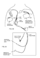
- FIG. 2 is a perspective and somewhat schematic view of a prior art active implantable medical device (AIMD) including a lead wire directed to the heart of a patient;
- AIMD active implantable medical device
- FIG. 10 is a diagram similar to FIGS. 8 and 9 , illustrating a bipolar lead wire system with a distal TIP and RING, typically used in a cardiac pacemaker;
- FIG. 13 is a graph showing impedance versus frequency for the parallel tank band stop circuit of FIG. 11 ;
- FIG. 31 is a perspective view of another embodiment of a two-layer inductive coil
- FIG. 40 is a sectional view of a basic cell ABCD representing the turn-to-turn capacitance.
- 100 C shows a cardiac pacemaker which is well-known in the art.
- 100 D includes the family of left ventricular assist devices (LVAD's), and artificial hearts, including the recently introduced artificial heart known as the Abiocor.
- 100 E includes an entire family of drug pumps which can be used for dispensing of insulin, chemotherapy drugs, pain medications and the like. Insulin pumps are evolving from passive devices to ones that have sensors and closed loop systems. That is, real time monitoring of blood sugar levels will occur. These devices tend to be more sensitive to EMI than passive pumps that have no sense circuitry or externally implanted lead wires.
- 100 F includes a variety of external or implantable bone growth stimulators for rapid healing of fractures.
- 100 G includes urinary incontinence devices.
- 100 H includes the family of pain relief spinal cord stimulators and anti-tremor stimulators.
- 100 H also includes an entire family of other types of neurostimulators used to block pain.
- 100 I includes a family of implantable cardioverter defibrillators (ICD) devices and also includes the family of congestive heart failure devices (CHF). This is also known in the art as cardio resynchronization therapy devices, otherwise knows as CRT devices.
- 100 J illustrates an externally worn pack. This pack could be an external insulin pump, an external drug pump, an external neurostimulator, a Holter monitor with skin electrodes or even a ventricular assist device power pack.
- 100 K illustrates the insertion of an external probe or catheter. These probes can be inserted into the femoral artery, for example, or in any other number of locations in the human body.
- a rectangular quadpolar feedthrough capacitor 120 which has an external metalized termination surface 122 . It includes embedded electrode plate sets 124 and 126 . Electrode plate set 124 is known as the ground electrode plate set and is terminated at the outside of the capacitor 120 at the termination surface 122 . These ground electrode plates 124 are electrically and mechanically connected to the ferrule 108 of the hermetic terminal assembly 106 using a thermosetting conductive polyimide or equivalent material 128 (equivalent materials will include solders, brazes, conductive epoxies and the like). In turn, the hermetic seal terminal assembly 106 is designed to have its titanium ferrule 108 laser welded 130 to the overall housing 102 of the AIMD 100 . This forms a continuous hermetic seal thereby preventing body fluids from penetrating into and causing damage to the electronics of the AIMD.
- the lead wires 104 and insulator 136 be hermetically sealed, such as by the gold brazes or glass seals 132 and 134 .
- the gold braze 132 wets from the titanium ferrule 108 to the alumina ceramic insulator 136 .
- the ceramic alumina insulator 136 is also gold brazed at 134 to each of the lead wires 104 .
- the RF telemetry pin 116 is also gold brazed at 138 to the alumina ceramic insulator 136 . It will be obvious to those skilled in the art that there are a variety of other ways of making such a hermetic terminal. This would include glass sealing the leads into the ferrule directly without the need for the gold brazes.
- the RF telemetry pin 116 has not been included in the area of the feedthrough capacitor 120 .
- the reason for this is the feedthrough capacitor 120 is a very broadband single element EMI filter which would eliminate the desirable telemetry frequency.
- FIG. 4 is a bottom view taken generally along line 4 - 4 in FIG. 3 .
- the amount of capacitance is determined by the overlap of the active electrode plate area 126 over the ground electrode plate area.
- the capacitance value is also related to the dielectric thickness or spacing between the ground electrode set 124 and the active electrode set 126 . Reducing the dielectric thickness increases the capacitance significantly while at the same time reducing its voltage rating. This gives the designer many degrees of freedom in selecting the capacitance value.
- FIG. 8 is a general diagram of a unipolar active implantable medical device system 100 .
- FIG. 8 could also be representative of an externally worn medical device such as a Holter monitor.
- the distal electrode 140 would typically be a scan or patch electrode.
- the housing 102 of the active implantable medical device 100 is typically titanium, ceramic, stainless steel or the like. Inside of the device housing are the AIMD electronic circuits.
- AIMDs include a battery, but that is not always the case. For example, for a Bion, it can receive its energy from an external pulsing magnetic field.
- a lead wire 104 is routed from the AIMD 100 to a point 140 where it is embedded in or affixed to body tissue.
- FIG. 11 is a schematic diagram showing a parallel combination of an inductor L and a capacitor C to be placed in the lead wire systems 104 previously described. This combination forms a parallel tank circuit or band stop filter 146 which will resonate at a particular frequency (f r ).
- the relationship between the parallel inductor L and capacitor C is also very important.
- using a very high value of inductor results in a high number of turns of very small wire.
- Using a high number of turns of very small diameter wire is contraindicated for two reasons. The first reason is that the long length of relatively small diameter wire results in a very high DC resistance for the inductor. This resistance is very undesirable because low frequency pacing or neurostimulator pulses would lose energy passing through the relatively high series resistance. This is also undesirable where the AIMD is sensing biologic signals.
- an air wound inductor is the ideal choice because it is not affected by MRI signals or fields. Because of the space limitations, however, the inductor will not be very volumetrically efficient. For this reason, it is preferable to keep the inductance value relatively low (in the order of 1 to 100 nanohenries).
- FIG. 13 is a graph showing impedance versus frequency for the parallel tank, band stop filter circuit 146 of FIG. 11 .
- the impedance measured between points A and B for the parallel tank circuit 146 shown in FIG. 11 is very low (zero) until one approaches the resonant frequency f r .
- these ideal components combine together to look like a very high or, ideally, an infinite impedance. The reason for this comes from the denominator of the equation Z ab for the impedance for the inductor in parallel with the capacitor shown as FIG. 14 .
- the inductive reactance is equal to the capacitive reactance, the two imaginary vectors cancel each other and go to zero. Referring to the equations in FIGS.
- a cardiac pacemaker it would be possible, for example, in the case of a cardiac pacemaker, to design the cardiac pacemaker for compatibility with one single popular MRI system.
- the pacemaker lead wire system has been designed to be compatible with 3 Tesla MRI systems.
- a distal TIP band stop filter 146 would be incorporated where the L and the C values have been carefully selected to be resonant at 128 MHz, presenting a high or almost infinite impedance at the MRI pulse frequency.
- FIG. 16 is a schematic drawing of the parallel tank circuit 146 of FIG. 11 , except in this case the inductor L and the capacitor C are not ideal. That is, the capacitor C has its own internal resistance R C , which is otherwise known in the industry as dissipation factor or equivalent series resistance (ESR).
- the inductor L also has a resistance R L . For those that are experienced in passive components, one would realize that the inductor L would also have some parallel capacitance. This parasitic capacitance comes from the capacitance associated with adjacent turns. However, the inductance value contemplated is so low that one can assume that at MRI pulse frequencies, the inductor's parallel capacitance is negligible.
- the capacitor C also has some internal inductance which would appear in series.
- the novel capacitors described below are very small or coaxial and have negligible series inductance. Accordingly, the circuit shown in FIG. 16 is a very good approximation model for the novel parallel tank circuits 146 as described herein.
- the frequency f is close to zero (DC)
- biologic signals are low frequency, typically between 10 Hz and 1000 Hz.
- the inductive reactance X L will be very close to zero ohms.
- the impedance between points A and B in FIG. 16 will equal to R L .
- the resistance of the inductor (R L ) should be kept as small as possible to minimize attenuation of biologic signals or attenuation of stimulation pulses to body tissues. This will allow biologic signals to pass through the band stop filter 146 freely. It also indicates that the amount of capacitive loss R C is not particularly important.
- FIG. 17 is a drawing of the unipolar AIMD lead wire system, previously shown in FIG. 8 , with the band stop filter 146 of the present invention added near the distal electrode 140 .
- the presence of the tank circuit 146 will present a very high impedance at one or more specific MRI RF pulse frequencies. This will prevent currents from circulating through the distal electrode 140 into body tissue at this selected frequency(s). This will provide a very high degree of important protection to the patient so that overheating does not cause tissue damage.
- FIG. 18 is a representation of the novel band stop tank filter 146 using switches that open and close at various frequencies to illustrate its function.
- Inductor L has been replaced with a switch S L .
- the switch S L When the impedance of the inductor is quite low, the switch S L will be closed.
- the impedance or inductive reactance of the inductor When the impedance or inductive reactance of the inductor is high, the switch S L will be shown open.
- the capacitor element C When the capacitive reactance looks like a very low impedance, the capacitor switch S C will be shown closed. When the capacitive reactance is shown as a very high impedance, the switch S C will be shown open. This analogy is best understood by referring to FIGS. 19, 20 and 21 .
- FIG. 20 is a model of the novel band stop filter 146 at its resonant frequency.
- a parallel tank circuit is at resonance, it presents a very high impedance to the overall circuit. Accordingly, both switches S L and S C are shown open. For example, this is how the band stop filter 146 prevents the flow of MRI currents through pacemaker lead wires and/or into body tissue at a selected MRI RF pulsed frequency.
- FIG. 21 is a model of the band stop filter 146 at high frequency.
- inductors tend to look like open circuits. Accordingly, switch S L is shown open.
- switch S C is closed. It should be noted that real capacitors are not ideal and tend to degrade in performance at high frequency. This is due to the capacitor's equivalent series inductance and equivalent series resistance. Fortunately, for the present invention, it is not important how lossy (resistive) the capacitor element C gets at high frequency. This will only serve to attenuate unwanted electromagnetic interference from flowing in the lead wire system.
- FIG. 22 is a decision tree block diagram that better illustrates the design process herein.
- Block 148 is an initial decision step the designer must make.
- capacitance For illustrative purposes, we will start with a value of capacitance that is convenient. This value of capacitance is generally going to relate to the amount of space available in the AIMD lead wire system and other factors. These values for practical purposes generally range in capacitance value from a few tens of picofarads up to about 10,000 picofarads. This puts practical boundaries on the amount of capacitance that can be effectively packaged within the scope of the present invention. However, that is not intended to limit the general principles of the present invention, but just describe a preferred embodiment.
- step 160 If the capacitance value that is determined in step 160 is realizable, then one goes on and finalizes the design. However, if it is not realizable, then one can go back up to step 156 , assume a different value of L and go through the decision tree again. This is done over and over until one finds combinations of L and C that are practical for the overall design.
- the predetermined frequency would be the MRI pulsed frequency.
- Efficiency of the overall tank circuit 146 is also measured in terms of a quality factor, Q, although this factor is defined differently than the one previously mentioned for discrete capacitors and inductors.
- Q quality factor
- f r is the resonance frequency
- ⁇ f 3dB shown as points a and b in FIG. 23 is the bandwidth of the band stop filter 146 .
- Bandwidth is typically taken as the difference between the two measured frequencies, f 1 and f 2 , at the 3 dB loss points as measured on an insertion loss chart, and the resonance frequency is the average between f 1 and f 2 . As can be seen in this relationship, higher Q values result in a narrower 3 dB bandwidth.
- the “Q” or quality factor of the tank circuit is very important. As mentioned, it is desirable to have a very low loss circuit at low frequencies such that the biological signals not be undesirably attenuated.
- the quality factor not only determines the loss of the filter, but also affects its 3 dB bandwidth. If one does a plot of the filter response curve (Bode plot), the 3 dB bandwidth determines how sharply the filter will rise and fall. With reference to curve 166 of FIG. 23 , for a tank that is resonant at 128 MHz, an ideal response would be one that had infinite attenuation at 128 MHz, but had zero attenuation at low frequencies below 1 KHz.
- the performance of the circuit is directly related to the efficiency of both the inductor and the capacitor; the less efficient each component is, the more heat loss that results, and this can be expressed by the addition of resistor elements to the ideal circuit diagram.
- the effect of lower Q in the tank circuit is to broaden the resonance peak about the resonance frequency. By deliberately using a low Q capacitor, one can broaden the resonance such that a high impedance (high attenuation) is presented at multiple MRI RF frequencies, for example 64 MHz and 128 MHz.
- curve 164 wherein a low resistive loss high Q inductor has been used in combination with a relatively high ESR low Q capacitor. This has a very desirable effect in that at very low frequencies, the impedance of the tank circuit 146 is essentially zero ohms (or zero dB loss). This means that biologic frequencies are not undesirably attenuated. However, one can see that the 3 db bandwidth is much larger. This is desirable as it will block multiple RF frequencies. As one goes even higher in frequency, curve 164 will desirably attenuate other high frequency EMI signals, such as those from cellular telephones, microwave ovens and the like.
- R C By adding a separate discrete component in series with the capacitor element. For example, one could install a small capacitor chip that had a very low equivalent series resistance and place it in series with a resistor chip. This would be done to deliberately raise the value of R C in the circuit as shown in FIG. 17 . By carefully adjusting this value of R C , one could then achieve the ideal curve 164 as shown in FIG. 23 .
- FIG. 24 is a tracing of an actual patient X-ray. This particular patient required both a cardiac pacemaker 100 C and an implantable cardioverter defibrillator 100 I.
- the corresponding lead wire system 104 makes for a very complicated antenna and loop coupling situation. The reader is referred to the article entitled, “Estimation of Effective Lead Loop Area for Implantable Pulse Generator and Implantable Cardioverter Defibrillators” provided by the AAMI Pacemaker EMC Task Force.
- the band stop filters 146 of the present invention would need to be placed at least in the distal TIP in the right atrium and the distal TIP in the right ventricle from the cardiac pacemaker.
- ICD implantable cardioverter defibrillator
- ICDs implantable cardioverter defibrillators
- FIG. 25 is a line drawing of an actual patient cardiac X-ray of one of the newer bi-ventricular lead wire systems with various types of electrode TIPS shown.
- the new bi-ventricular systems are being used to treat congestive heart failure, and make it possible to implant leads outside of the left ventricle. This makes for a very efficient pacing system; however, the lead wire system 104 is quite complex.
- a lead wire system 104 such as those described in FIGS. 8, 9, 10 and 11 , are exposed to a time varying electromagnetic field, electric currents can be induced into such lead wire systems.
- band stop filters 146 would be required at each of the three distal TIPs and optionally at RING and SVC locations.
- FIG. 26 illustrates a single chamber bipolar cardiac pacemaker lead wire showing the distal TIP 142 and the distal RING 144 electrodes. This is a spiral wound system where the RING coil 104 is wrapped around the TIP coil 104 ′. There are other types of pacemaker lead wire systems in which these two leads lay parallel to one another (known as a bifilar lead system).
- FIG. 27 is a schematic illustration of the area 27 - 27 in FIG. 26 .
- band stop filters 146 and 146 ′ have been placed in series with each of the respective TIP and RING circuits. Accordingly, at MRI pulsed frequencies, an open circuit will be presented thereby stopping the flow of undesirable RF current.
- FIG. 28 illustrates an alternate form of a bandstop filter previously illustrated in FIG. 27 as elements 146 and 146 ′. It was earlier stated that, “It is also possible to use a single inductive component that has significant parasitic capacitance between its adjacent turns. A careful designer, using multiple turns, could create enough parasitic capacitance such that the coil becomes self-resonant at a predetermined frequency. In this case, the predetermined frequency would be the MRI RF-pulsed frequency.”
- lead conductor 104 , 104 ′ is connected to a single layer resonant coil structure 170 . It is well known to those skilled in the art that coiling of a conductor, as shown in FIG.
- inductor 28 creates a single layer solenoid inductor.
- the conductor material be insulated.
- various types of insulative wire are available in the industry for manufacturing inductor coils.
- FIG. 29 is a sectional view taken from section 29 - 29 from FIG. 28 illustrating that the inductor coil conductor 172 consists of a solid metallic center 174 which is surrounded by an insulative material 176 .
- the insulation material 176 is very important. This is because parasitic capacitance is formed between adjacent turns of coil 170 causing it to become self-resonant at an MRI RF-pulsed frequency. Both the dielectric constant of the insulation and the thickness of the insulation are very important. In general, capacitance is equal to the dielectric constant times the area times the number of turns divided by the dielectric thickness. For example, if one makes the dielectric thickness 176 very thin and winds the coil turns very tightly together, the parasitic capacitance will increase.
- the equation for resonant frequency is previously described in FIGS. 12 and 13 .
- the self-resonant inductor structure 170 has been designed, for example, to replace tank filters 146 and/or 146 ′ as previously illustrated in FIG. 27 .
- the self-resonant coil or tank filter of FIG. 28 could be put in series with any implantable lead conductor, such as those used in neurostimulator applications and the like.
- a more complete example of these types of AIMDs is previously described in FIG. 1 .
- the self-resonant inductor structure 170 would also be very useful for a probe or catheter 100 K, as shown in FIG. 1 , during MRI-guided intervention procedures, such as RF ablation.
- the L/C ratio is very important.
- a single length of wire 172 has been wounded in one direction and then wound back, forming a two-layer self-resonant inductor. Parasitic capacitance is still formed between the adjacent turns and also between the coils of the inner layer and the outer layer.
- the structure shown in FIG. 30 is not a preferred embodiment for human implant. The reason for this is the insulative conductor 172 and 172 ′ that forms the coil inductor both emerge from one end. In this case, both are shown emerging from the right side. This makes this type of structure particularly inconvenient for placement in series in an implantable lead conductor. Implantable lead conductors must be very small in diameter for transvenous insertion or for tunneling through human tissues.
- FIG. 32 is very similar to FIG. 30 , except that the return wire 172 ′ is disposed between the inner coiled conductor 172 and the outer coiled conductor 172 ′′.
- the return wire 172 ′ may be coiled as well, or as shown here, a straight wire conductor 172 ′ connecting the inner coiled conductor 172 and the outer coiled conductor 172 ′′.
- the self-resonant inductor 170 is connected in series along a portion of the length of the lead conductor 104 .
- the self-resonant inductor 170 includes a single length of conductive material including a dielectric coating 176 substantially surrounding the single length of conductive material.
- FIG. 33 is very similar to FIG. 30 except this is a three-layer self-resonant coil construction.
- the self-resonant coil of FIG. 33 is wound from one continuous conductor starting from the right where the turns are wrapped around a mandrel (not shown) all the way to the left and then wrapped back over itself to the right and then wrapped back over itself tightly to the left at point 172 ′.
- the self-resonant inductor 170 is connected in series along a portion of the length of the lead conductor 104 .
- the self-resonant inductor 170 may be made from a single length of conductive material comprising a dielectric coating 176 substantially surrounding the single length of conductive material.
- the self-resonant inductor 170 includes a first insulated coiled or spiral conductor 194 disposed along an inductor section 200 spanning in a first direction from a first location 202 to a second location 204 .
- a second insulated coiled or spiral conductor 196 is disposed along the inductor section 200 spanning in a second direction from the second location 204 to the first location 202 . Note that the second direction is opposite the first direction.
- a third insulated coiled or spiral conductor 198 is disposed along the inductor section 200 spanning in the first direction from the first location 202 to the second location 204 .
- FIG. 34 is a cross-sectional view taken from section 34 - 34 from FIG. 33 .
- the three layers are tightly packed in both the x and y direction as shown.
- the wire insulation is not shown, but it will be well understood that it is always present as illustrated in FIG. 29 .
- FIG. 34 is a particularly sufficient structure, in that, it provides a very high amount of inductance due to the overlapping solenoid turns while at the same time providing sufficient parasitic capacitance so that it can be made to be self-resonant at an MRI RF-pulsed frequency.
- the diameter of the center core and the resistivity of the center core 174 are also very important as resistance of the inductor depends on cross sectional area and resistivity of the conductor wire.
- the resistance of the conductor is very important in determining the Q and the resulting 3-dB bandwidth of the completed tank filter.
- FIG. 16 to element R L One is referred to FIG. 16 to element R L to see where this resistance appears in the circuit.
- the resistance will go up and the Q of the inductor will go down. This results in an increased 3-dB bandwidth as previously described in FIG. 23 .
- the resistance of the inductor is particularly high, one would have a resulting low Q curve, previously illustrated as curve 162 in FIG. 23 .
- the coil structures of FIGS. 28 through 34 are wound on a mandrel (not shown) and then the mandrel was removed.
- the wires being wound would have insulation material that is thermoplastic.
- the adjacent coils are then bonded to each other so that the coil becomes free standing.
- the mandrel 178 as illustrated in FIG. 35 and leave it in place to provide structural rigidity.
- the coil turns could be overlaid with some sort of a thermoplastic insulative material to hold them all tightly packed in place.
- the mandrel 178 could be hollow or it could be solid all the way through the center.
- a preferred embodiment would be a solid core in order to transmit maximum torque during physician implantation of the active fixation or screw tip.
- FIG. 36 is very similar to FIG. 34 , which was a 3-layer inductor with coil layers 194 , 196 and 198 .
- the purpose of FIG. 36 is to illustrate that any number of coil layers “n” can be added to the inductors previously described in FIGS. 28 through 35 .
- a 3-layer coil is depicted.
- a continuous wire is wound from left to right and then from right to left and once again from left to right.
- any number of additional layers 206 , 208 or even “n” layers can be added to this wound structure.
- the number of layers added is an even number, such as having only layers 194 , 196 , 198 and 206 , then the inductor as shown in FIG. 36 would require a return wire as previously illustrated in FIG. 31 or 32 .
- the reason for this is that it is important that the self-resonant inductor end connections 172 and 172 ′ be at opposite ends of the structure and be aligned axially for simple insertion into an implantable lead conductor.
- Implantable leads are inserted transvenously, epicardially or by tunneling through patient tissue. Accordingly, they must be very small in diameter.
- the optimal place for the return wire (when “n” is an even number) is back through the center of the coil structure, as shown in FIG. 31 .
- a return wire could be on the outside (not optimal) of the coil layers, or it could even be interleaved between adjacent coil layers (also not optimal). Interleaving between coil layers was previously illustrated in FIG. 32 .
- an odd number of layers illustrated as comprising wire 194 , 196 , 198 , 206 and 208 would produce a 5-layer self-resonant solenoid/inductor.
- the first layer 194 is formed.
- layer 196 is formed by winding back in the opposite direction until the location in the general area of 172 ′ is reached. This forms the second layer of the inductor.
- the third layer 198 is then formed by winding once again from left to right stopping the winding in close proximity to the end of the inductor 172 .
- the fourth layer 206 is then formed by winding from the right back to the left.
- the fifth layer 208 (which in this example is the last or outer layer) is formed by winding, once again, from the left, in the general area of 172 ′ back to the right and would terminate at 172 (not shown). This may seem somewhat confusing as location 172 is drawn for a 3-layer inductor, and not an “n”-layer inductor. Nevertheless, it will be obvious to those skilled in the art that the outermost winding in this example produces a 5-layer inductor, whereas the outermost winding as illustrated in FIG. 36 produces a 3-layer inductor.
- each individual layer is wound around the x axis and there are generally any number of coils that are tightly packed adjacent to each other. In general, they are insulated (insulation not shown for simplicity). Each layer is formed by winding the wire back on top of the coils of the previous layer. Each coil layer causes the inductor to get larger in diameter as each additional layer is added.
- a coil turn is one complete 360 degree turn of wire around a center axis or mandrel.
- Each coil turn causes the inductor to get longer in length along the x axis.
- a layer is one complete layer of coils that are wound along this x axis thereby forming a complete inductor.
- This can be a single layer inductor, as previously illustrated in FIG. 28 ; it could be a 2-layer inductor, as illustrated in FIG. 30 ; a 3-layer inductor, as illustrated in FIG. 34 ; or an “n”-layer inductor, as illustrated in FIG. 36 .
- the x, y and z axes are also defined.
- the x axis is the axis that runs along the central axis of the coil.
- the diameter of the coil is represented in the y and z axes.
- the y axis comes straight out of the page at the reader and is perpendicular to the x and z.
- the term “lead” refers to an implantable lead body and its associated insulation and conductors and the like.
- a lead conductor can be one or more wires or other types of conductors that are embedded within the lead.
- the term “leadwire” generally refers to wires that are inside the AIMD housing and are used for connection between electronic circuits.
- FIG. 37 is a sectional view taken generally from section 37 - 37 of FIG. 36 .
- FIG. 37 illustrates a few of the parasitic capacitances just to illustrate the complexity of the structure.
- a parasitic capacitance 182 is formed between adjacent turns.
- a parasitic capacitance 186 is also formed between each wire between layers.
- a parasitic capacitance 184 is also formed along the diagonal between conductors of different layers that are stacked at an angle. If an optional shield 190 is used, an additional parasitic capacitance 188 would also be formed particularly between the outer wires that line the inside of the metal shield 190 . Modeling of this parasitic capacitance will be discussed in subsequent drawings.
- FIG. 38 is very similar to FIG. 37 and is a cross-sectional view 38 - 38 taken from FIG. 36 .
- special cored conductors are used.
- a wide range of biocompatible materials can be used for both conductor 174 and insulation 176 .
- the conductor wire selection primarily depends on the electromechanical properties of the inductor.
- Various clad, plated, electroplated, anodized or core combination materials like core wire or filled tubes can be used to optimize the electromechanical properties of the inductor.
- a mechanically strong material such as but not limited to MP35N, Nitinol, tungston, tantalum, niobium, Co—Cr—Mo alloys, stainless steel alloys, especially stainless steel alloys with Mo, Ni, Cr combinations, carbon steels, may be used as the outer layer.
- the core material may be a more highly conductive material but perhaps a less mechanically strong material such as but not limited to silver, platinum and its alloys like platinum-iridium or platinum-tungsten, tantalum, gold, palladium, nitinol, titanium and titanium alloys. It is not necessary that the core material be non-toxic and biocompatible, but it is very important that the outer layer be of non-toxic and biocompatible material. When they are both biocompatible, it will be obvious to those skilled in the art that these materials may be used interchangeably for the inner core or the outer layer depending on the ultimate physical and electrical behavior desired for a particular application. Additionally, the percentage of clad and core material can be adjusted to meet specific electrical and/or mechanical properties for the finished conductor wire.
- FIG. 41 is a flow chart showing the essential steps one goes through in designing the self-resonant coil of the present invention.
- one selects the wire type and the wire size that will be used to wind the inductor structure.
- One selects the type of insulation, the insulation thickness and in particular, its dielectric constant.
- One uses the equations from the referenced Massarini paper, SEMCAD or another modeling program to estimate the number of turns required to come up with the proper inductance, the L/C ratio and the amount of capacitance.
- FIG. 12 uses the equations from the referenced Massarini paper, SEMCAD or another modeling program to estimate the number of turns required to come up with the proper inductance, the L/C ratio and the amount of capacitance.
- FIG. 12 calculate the resonant frequency. This is an iterative process as one selects the resonant frequency to be centered at MRI RF-pulsed frequency. For example, for a 1.5 Tesla scanner, one would select a resonant frequency f r approximately
Abstract
Description
Claims (70)
Priority Applications (1)
| Application Number | Priority Date | Filing Date | Title |
|---|---|---|---|
| US13/680,083 US9295828B2 (en) | 2001-04-13 | 2012-11-18 | Self-resonant inductor wound portion of an implantable lead for enhanced MRI compatibility of active implantable medical devices |
Applications Claiming Priority (6)
| Application Number | Priority Date | Filing Date | Title |
|---|---|---|---|
| US28372501P | 2001-04-13 | 2001-04-13 | |
| US10/123,534 US7844319B2 (en) | 1998-11-04 | 2002-04-15 | Systems and methods for magnetic-resonance-guided interventional procedures |
| US11/423,073 US8244370B2 (en) | 2001-04-13 | 2006-06-08 | Band stop filter employing a capacitor and an inductor tank circuit to enhance MRI compatibility of active medical devices |
| US12/170,811 US8897887B2 (en) | 2006-06-08 | 2008-07-10 | Band stop filter employing a capacitor and an inductor tank circuit to enhance MRI compatibility of active medical devices |
| US12/891,292 US8437865B2 (en) | 2001-04-13 | 2010-09-27 | Shielded network for an active medical device implantable lead |
| US13/680,083 US9295828B2 (en) | 2001-04-13 | 2012-11-18 | Self-resonant inductor wound portion of an implantable lead for enhanced MRI compatibility of active implantable medical devices |
Related Parent Applications (2)
| Application Number | Title | Priority Date | Filing Date |
|---|---|---|---|
| US12/170,811 Continuation-In-Part US8897887B2 (en) | 2001-04-13 | 2008-07-10 | Band stop filter employing a capacitor and an inductor tank circuit to enhance MRI compatibility of active medical devices |
| US12/891,292 Continuation-In-Part US8437865B2 (en) | 2001-04-13 | 2010-09-27 | Shielded network for an active medical device implantable lead |
Publications (2)
| Publication Number | Publication Date |
|---|---|
| US20130073021A1 US20130073021A1 (en) | 2013-03-21 |
| US9295828B2 true US9295828B2 (en) | 2016-03-29 |
Family
ID=47881374
Family Applications (1)
| Application Number | Title | Priority Date | Filing Date |
|---|---|---|---|
| US13/680,083 Active US9295828B2 (en) | 2001-04-13 | 2012-11-18 | Self-resonant inductor wound portion of an implantable lead for enhanced MRI compatibility of active implantable medical devices |
Country Status (1)
| Country | Link |
|---|---|
| US (1) | US9295828B2 (en) |
Cited By (1)
| Publication number | Priority date | Publication date | Assignee | Title |
|---|---|---|---|---|
| US10603488B2 (en) | 2017-02-10 | 2020-03-31 | Oscor Inc. | Implantable medical devices having diamagnetic conductors and contacts |
Families Citing this family (8)
| Publication number | Priority date | Publication date | Assignee | Title |
|---|---|---|---|---|
| US8600520B2 (en) * | 2012-04-18 | 2013-12-03 | Pacesetter, Inc. | Implantable lead assembly having a plurality of inductors |
| US20150088237A1 (en) * | 2013-09-23 | 2015-03-26 | Boston Scientific Neuromodulation Corporation | Lead extensions for use with electrical stimulation systems and methods of making and using the lead extensions |
| US20160059014A1 (en) * | 2014-09-02 | 2016-03-03 | Benjamin Peter Johnston | Event Detection In An Implantable Auditory Prosthesis |
| EP3292612B1 (en) * | 2015-05-04 | 2022-08-24 | The Regents of The University of Colorado, A Body Corporate | Wireless power transfer |
| US9974949B2 (en) * | 2015-10-16 | 2018-05-22 | Cyberonics, Inc. | MRI-safe implantable lead assembly |
| US11500048B2 (en) * | 2019-01-23 | 2022-11-15 | Inkspace Imaging, Inc. | Flexible resonant trap circuit |
| CN110797637B (en) * | 2019-10-18 | 2022-05-06 | 青岛大学 | Broadband helical antenna and design method thereof |
| US20210186591A1 (en) * | 2019-12-23 | 2021-06-24 | Gyrus Acmi, Inc. D/B/A Olympus Surgical Technologies America | Inductive power joint allowing unrestricted rotation |
Citations (369)
| Publication number | Priority date | Publication date | Assignee | Title |
|---|---|---|---|---|
| US3871382A (en) | 1973-02-15 | 1975-03-18 | Pacesetter Syst | Heart stimulator system for rapid implantation and removal with improved integrity |
| US3968802A (en) | 1975-01-24 | 1976-07-13 | Medtronic, Inc. | Cautery protection circuit for a heart pacemaker |
| US3980975A (en) | 1975-09-08 | 1976-09-14 | Varian Associates | Broadband microwave bias network |
| US4188598A (en) | 1977-11-07 | 1980-02-12 | Hunt Morris C | Electrical filter |
| US4236127A (en) | 1977-04-13 | 1980-11-25 | Pyrohm, Inc. | Electrical frequency responsive structure |
| US4295467A (en) | 1979-05-24 | 1981-10-20 | Inverness International Corp. | Electrolysis apparatus with retractable probe |
| US4320763A (en) | 1979-10-10 | 1982-03-23 | Telectronics Pty. Limited | Protection device for pacemaker implantees |
| US4354880A (en) | 1979-10-01 | 1982-10-19 | Southwire Company | Method of forge-conditioning non-ferrous metals prior to rolling |
| US4424551A (en) | 1982-01-25 | 1984-01-03 | U.S. Capacitor Corporation | Highly-reliable feed through/filter capacitor and method for making same |
| US4431005A (en) | 1981-05-07 | 1984-02-14 | Mccormick Laboratories, Inc. | Method of and apparatus for determining very accurately the position of a device inside biological tissue |
| US4437474A (en) | 1982-07-16 | 1984-03-20 | Cordis Corporation | Method for making multiconductor coil and the coil made thereby |
| US4445501A (en) | 1981-05-07 | 1984-05-01 | Mccormick Laboratories, Inc. | Circuits for determining very accurately the position of a device inside biological tissue |
| JPS60141034U (en) | 1984-02-29 | 1985-09-18 | カシオ計算機株式会社 | keyboard |
| US4572198A (en) | 1984-06-18 | 1986-02-25 | Varian Associates, Inc. | Catheter for use with NMR imaging systems |
| US4585001A (en) | 1982-09-28 | 1986-04-29 | Norland Corporation | Cardiac pacer signal detector |
| JPS61181925U (en) | 1985-05-07 | 1986-11-13 | ||
| US4633181A (en) | 1983-08-11 | 1986-12-30 | Regents Of The University Of Calif. | Apparatus and method for increasing the sensitivity of a nuclear magnetic resonance probe |
| US4643186A (en) | 1985-10-30 | 1987-02-17 | Rca Corporation | Percutaneous transluminal microwave catheter angioplasty |
| US4654880A (en) | 1983-12-09 | 1987-03-31 | Minnesota Mining And Manufacturing Company | Signal transmission system |
| US4672972A (en) | 1984-08-13 | 1987-06-16 | Berke Howard R | Solid state NMR probe |
| WO1987004080A3 (en) | 1986-01-13 | 1987-08-13 | Donald Bernard Longmore | Surgical catheters |
| US4689621A (en) | 1986-03-31 | 1987-08-25 | The United States Of America As Represented By The Administrator Of The National Aeronautics And Space Administration | Temperature responsive transmitter |
| US4712555A (en) | 1984-10-19 | 1987-12-15 | Siemens-Elema Ab | Physiologically responsive pacemaker and method of adjusting the pacing interval thereof |
| US4746864A (en) | 1986-03-31 | 1988-05-24 | Kabushiki Kaisha Toshiba | Magnetic resonance imaging system |
| US4754752A (en) | 1986-07-28 | 1988-07-05 | Robert Ginsburg | Vascular catheter |
| US4757820A (en) | 1985-03-15 | 1988-07-19 | Kabushiki Kaisha Toshiba | Ultrasound therapy system |
| US4766381A (en) | 1987-08-12 | 1988-08-23 | Vanderbilt University | Driven inversion spin echo magnetic resonance imaging |
| US4788980A (en) | 1986-07-18 | 1988-12-06 | Siemens-Pacesetter, Inc. | Pacemaker having PVC response and PMT terminating features |
| US4799499A (en) | 1985-08-17 | 1989-01-24 | Bisping Hans Juergen | Implantable electrode with active fixation means |
| US4813429A (en) | 1986-05-12 | 1989-03-21 | Biodan Medical Systems Ltd. | Catheter and probe |
| US4823812A (en) | 1986-05-12 | 1989-04-25 | Biodan Medical Systems Ltd. | Applicator for insertion into a body opening for medical purposes |
| US4832023A (en) | 1987-06-03 | 1989-05-23 | Mcm Laboratories, Inc. | Method and apparatus for reducing blockage in body channels |
| US4839594A (en) * | 1987-08-17 | 1989-06-13 | Picker International, Inc. | Faraday shield localized coil for magnetic resonance imaging |
| US4859950A (en) | 1987-05-26 | 1989-08-22 | Elscint Ltd | Balun circuit for radio frequency coils in magnetic resonance systems |
| US4858623A (en) | 1987-07-13 | 1989-08-22 | Intermedics, Inc. | Active fixation mechanism for lead assembly of an implantable cardiac stimulator |
| US4932411A (en) | 1984-08-09 | 1990-06-12 | Siemens Aktiengesellschaft | Intervivo coil for a nuclear magnetic resonance tomographic apparatus |
| US4940052A (en) | 1989-01-25 | 1990-07-10 | Siemens-Pacesetter, Inc. | Microprocessor controlled rate-responsive pacemaker having automatic rate response threshold adjustment |
| US4960106A (en) | 1987-04-28 | 1990-10-02 | Olympus Optical Co., Ltd. | Endoscope apparatus |
| US4977298A (en) | 1989-09-08 | 1990-12-11 | Matsushita Electric Industrial Co., Ltd. | Panel switch |
| US4989608A (en) | 1987-07-02 | 1991-02-05 | Ratner Adam V | Device construction and method facilitating magnetic resonance imaging of foreign objects in a body |
| US4991580A (en) | 1989-03-30 | 1991-02-12 | Invivo Research, Inc. | Method of improving the quality of an electrocardiogram obtained from a patient undergoing magnetic resonance imaging |
| US5019075A (en) | 1984-10-24 | 1991-05-28 | The Beth Israel Hospital | Method and apparatus for angioplasty |
| EP0145430B1 (en) | 1983-12-09 | 1991-05-29 | Cochlear Corporation | Signal transmission system |
| US5044375A (en) | 1989-12-08 | 1991-09-03 | Cardiac Pacemakers, Inc. | Unitary intravascular defibrillating catheter with separate bipolar sensing |
| US5052404A (en) | 1989-03-02 | 1991-10-01 | The Microspring Company, Inc. | Torque transmitter |
| US5063348A (en) | 1989-02-23 | 1991-11-05 | Kabushiki Kaisha Toshiba | Magnetic resonance imaging system |
| US5095911A (en) | 1990-05-18 | 1992-03-17 | Cardiovascular Imaging Systems, Inc. | Guidewire with imaging capability |
| US5099208A (en) | 1989-10-05 | 1992-03-24 | Vanderbilt University | Method for magnetic resonance imaging and related apparatus |
| WO1992010213A1 (en) | 1990-12-07 | 1992-06-25 | Board Of Regents, The University Of Texas System | Molecular sieve-enclosed paramagnetic ion for diagnosis |
| US5167233A (en) | 1991-01-07 | 1992-12-01 | Endosonics Corporation | Dilating and imaging apparatus |
| US5178618A (en) | 1991-01-16 | 1993-01-12 | Brigham And Womens Hospital | Method and device for recanalization of a body passageway |
| US5190046A (en) | 1992-05-01 | 1993-03-02 | Shturman Cardiology Systems, Inc. | Ultrasound imaging balloon catheter |
| US5197468A (en) | 1990-02-13 | 1993-03-30 | Proctor Paul W | Device for protecting an electronic prosthesis from adverse effects of RF and/or electrostatic energy |
| US5209233A (en) | 1985-08-09 | 1993-05-11 | Picker International, Inc. | Temperature sensing and control system for cardiac monitoring electrodes |
| US5211165A (en) | 1991-09-03 | 1993-05-18 | General Electric Company | Tracking system to follow the position and orientation of a device with radiofrequency field gradients |
| US5217010A (en) | 1991-05-28 | 1993-06-08 | The Johns Hopkins University | Ecg amplifier and cardiac pacemaker for use during magnetic resonance imaging |
| US5222506A (en) | 1991-07-29 | 1993-06-29 | Medtronic, Inc. | Implantable medical lead with electrical cross-over adaptor |
| US5246438A (en) | 1988-11-25 | 1993-09-21 | Sensor Electronics, Inc. | Method of radiofrequency ablation |
| US5251120A (en) | 1986-07-23 | 1993-10-05 | Steve Smith | Harmonic noise isolation and power factor correction network |
| US5271400A (en) | 1992-04-01 | 1993-12-21 | General Electric Company | Tracking system to monitor the position and orientation of a device using magnetic resonance detection of a sample contained within the device |
| US5300108A (en) | 1993-01-05 | 1994-04-05 | Telectronics Pacing Systems, Inc. | Active fixation lead with a dual-pitch, free spinning compound screw |
| US5306291A (en) | 1992-02-26 | 1994-04-26 | Angeion Corporation | Optimal energy steering for an implantable defibrillator |
| US5307808A (en) | 1992-04-01 | 1994-05-03 | General Electric Company | Tracking system and pulse sequences to monitor the position of a device using magnetic resonance |
| US5307814A (en) | 1991-09-17 | 1994-05-03 | Medrad, Inc. | Externally moveable intracavity probe for MRI imaging and spectroscopy |
| US5318025A (en) | 1992-04-01 | 1994-06-07 | General Electric Company | Tracking system to monitor the position and orientation of a device using multiplexed magnetic resonance detection |
| US5323778A (en) | 1991-11-05 | 1994-06-28 | Brigham & Women's Hospital | Method and apparatus for magnetic resonance imaging and heating tissues |
| US5323776A (en) | 1992-10-15 | 1994-06-28 | Picker International, Inc. | MRI compatible pulse oximetry system |
| US5333095A (en) | 1993-05-03 | 1994-07-26 | Maxwell Laboratories, Inc., Sierra Capacitor Filter Division | Feedthrough filter capacitor assembly for human implant |
| US5334193A (en) | 1992-11-13 | 1994-08-02 | American Cardiac Ablation Co., Inc. | Fluid cooled ablation catheter |
| US5334045A (en) | 1992-11-20 | 1994-08-02 | Siemens Pacesetter, Inc. | Universal cable connector for temporarily connecting implantable leads and implantable medical devices with a non-implantable system analyzer |
| US5348010A (en) | 1989-02-24 | 1994-09-20 | Medrea, Inc., Pennsylvania Corp., Pa. | Intracavity probe and interface device for MRI imaging and spectroscopy |
| US5352979A (en) | 1992-08-07 | 1994-10-04 | Conturo Thomas E | Magnetic resonance imaging with contrast enhanced phase angle reconstruction |
| US5358515A (en) | 1989-08-16 | 1994-10-25 | Deutsches Krebsforschungzentrum Stiftung Des Offentlichen Rechts | Microwave hyperthermia applicator |
| WO1994023782A1 (en) | 1993-04-14 | 1994-10-27 | Pharmacyclics, Inc. | Medical devices and materials having enhanced magnetic images visibility |
| US5363845A (en) | 1993-08-13 | 1994-11-15 | Medical Advances, Inc. | Breast coil for magnetic resonance imaging |
| US5365928A (en) | 1992-11-25 | 1994-11-22 | Medrad, Inc. | Endorectal probe with planar moveable MRI coil |
| US5398683A (en) | 1991-05-24 | 1995-03-21 | Ep Technologies, Inc. | Combination monophasic action potential/ablation catheter and high-performance filter system |
| US5400787A (en) | 1993-11-24 | 1995-03-28 | Magna-Lab, Inc. | Inflatable magnetic resonance imaging sensing coil assembly positioning and retaining device and method for using the same |
| US5404880A (en) | 1993-10-05 | 1995-04-11 | Board Of Regents Of University Of Nebraska | Scatter diagram analysis system and method for discriminating ventricular tachyarrhythmias |
| US5413104A (en) | 1992-11-10 | 1995-05-09 | Drager Medical Electronics B.V. | Invasive MRI transducers |
| US5419325A (en) | 1994-06-23 | 1995-05-30 | General Electric Company | Magnetic resonance (MR) angiography using a faraday catheter |
| US5428337A (en) | 1992-02-21 | 1995-06-27 | Vlt Corporation | Conductive winding |
| US5433717A (en) | 1993-03-23 | 1995-07-18 | The Regents Of The University Of California | Magnetic resonance imaging assisted cryosurgery |
| US5437277A (en) | 1991-11-18 | 1995-08-01 | General Electric Company | Inductively coupled RF tracking system for use in invasive imaging of a living body |
| US5443066A (en) | 1991-11-18 | 1995-08-22 | General Electric Company | Invasive system employing a radiofrequency tracking system |
| US5443489A (en) | 1993-07-20 | 1995-08-22 | Biosense, Inc. | Apparatus and method for ablation |
| US5447156A (en) | 1994-04-04 | 1995-09-05 | General Electric Company | Magnetic resonance (MR) active invasive devices for the generation of selective MR angiograms |
| US5451232A (en) | 1991-10-07 | 1995-09-19 | Medrad, Inc. | Probe for MRI imaging and spectroscopy particularly in the cervical region |
| EP0466424B1 (en) | 1990-07-06 | 1995-10-25 | Cardiometrics, Inc. | Torqueable guide wire assembly with male and female connectors |
| US5462055A (en) | 1994-08-23 | 1995-10-31 | Northrop Grumman Corporation | MRI/hyperthermia dual function antenna system |
| US5466254A (en) | 1993-09-22 | 1995-11-14 | Pacesetter, Inc. | Coronary sinus lead with atrial sensing capability |
| US5476483A (en) | 1994-06-10 | 1995-12-19 | Pacesetter, Inc. | System and method for modulating the base rate during sleep for a rate-responsive cardiac pacemaker |
| US5498261A (en) | 1991-12-20 | 1996-03-12 | Advanced Cardiovascular Systems, Inc. | Thermal angioplasty system |
| EP0557127A3 (en) | 1992-02-21 | 1996-03-20 | Scimed Life Systems Inc | Intravascular imaging guide wire apparatus and methods for use and manufacture |
| US5507743A (en) | 1993-11-08 | 1996-04-16 | Zomed International | Coiled RF electrode treatment apparatus |
| US5512825A (en) | 1994-11-25 | 1996-04-30 | The Johns Hopkins University | Method of minimizing dead-periods in magnetic resonance imaging pulse sequences and associated apparatus |
| US5540679A (en) | 1992-10-05 | 1996-07-30 | Boston Scientific Corporation | Device and method for heating tissue in a patient's body |
| US5545201A (en) | 1995-03-29 | 1996-08-13 | Pacesetter, Inc. | Bipolar active fixation lead for sensing and pacing the heart |
| US5558093A (en) | 1990-05-18 | 1996-09-24 | Cardiovascular Imaging Systems, Inc. | Guidewire with imaging capability |
| US5578008A (en) | 1992-04-22 | 1996-11-26 | Japan Crescent, Inc. | Heated balloon catheter |
| US5588432A (en) | 1988-03-21 | 1996-12-31 | Boston Scientific Corporation | Catheters for imaging, sensing electrical potentials, and ablating tissue |
| US5591218A (en) | 1993-08-11 | 1997-01-07 | Ela Medical, S.A. | Current limiter for implantable electronic device lead |
| US5590657A (en) | 1995-11-06 | 1997-01-07 | The Regents Of The University Of Michigan | Phased array ultrasound system and method for cardiac ablation |
| US5620476A (en) | 1995-11-13 | 1997-04-15 | Pacesetter, Inc. | Implantable medical device having shielded and filtered feedthrough assembly and methods for making such assembly |
| US5623241A (en) | 1992-09-11 | 1997-04-22 | Magna-Lab, Inc. | Permanent magnetic structure |
| US5629622A (en) | 1995-07-11 | 1997-05-13 | Hewlett-Packard Company | Magnetic field sense system for the protection of connected electronic devices |
| US5662108A (en) | 1992-09-23 | 1997-09-02 | Endocardial Solutions, Inc. | Electrophysiology mapping system |
| WO1997040396A1 (en) | 1996-04-25 | 1997-10-30 | The Johns Hopkins University | Method of magnetic resonance imaging and spectroscopic analysis and associated apparatus |
| US5685878A (en) | 1995-11-13 | 1997-11-11 | C.R. Bard, Inc. | Snap fit distal assembly for an ablation catheter |
| US5697958A (en) | 1995-06-07 | 1997-12-16 | Intermedics, Inc. | Electromagnetic noise detector for implantable medical devices |
| US5699801A (en) | 1995-06-01 | 1997-12-23 | The Johns Hopkins University | Method of internal magnetic resonance imaging and spectroscopic analysis and associated apparatus |
| US5716390A (en) | 1996-08-09 | 1998-02-10 | Pacesetter, Inc. | Reduced diameter active fixation pacing lead using concentric interleaved coils |
| US5715825A (en) | 1988-03-21 | 1998-02-10 | Boston Scientific Corporation | Acoustic imaging catheter and the like |
| US5722998A (en) | 1995-06-07 | 1998-03-03 | Intermedics, Inc. | Apparatus and method for the control of an implantable medical device |
| EP0673621B1 (en) | 1994-03-18 | 1998-03-04 | Schneider (Europe) Ag | A magnetic resonance imaging system for tracking a medical appliance |
| US5735887A (en) | 1996-12-10 | 1998-04-07 | Exonix Corporation | Closed-loop, RF-coupled implanted medical device |
| US5741321A (en) | 1996-01-11 | 1998-04-21 | Medtronic, Inc. | Active fixation medical electrical lead having improved turning tool |
| US5751539A (en) | 1996-04-30 | 1998-05-12 | Maxwell Laboratories, Inc. | EMI filter for human implantable heart defibrillators and pacemakers |
| US5759202A (en) | 1997-04-28 | 1998-06-02 | Sulzer Intermedics Inc. | Endocardial lead with lateral active fixation |
| US5769800A (en) | 1995-03-15 | 1998-06-23 | The Johns Hopkins University Inc. | Vest design for a cardiopulmonary resuscitation system |
| US5772693A (en) | 1996-02-09 | 1998-06-30 | Cardiac Control Systems, Inc. | Single preformed catheter configuration for a dual-chamber pacemaker system |
| US5775338A (en) | 1997-01-10 | 1998-07-07 | Scimed Life Systems, Inc. | Heated perfusion balloon for reduction of restenosis |
| US5779669A (en) | 1996-10-28 | 1998-07-14 | C. R. Bard, Inc. | Steerable catheter with fixed curve |
| US5782891A (en) | 1994-06-16 | 1998-07-21 | Medtronic, Inc. | Implantable ceramic enclosure for pacing, neurological, and other medical applications in the human body |
| US5800467A (en) | 1995-12-15 | 1998-09-01 | Pacesetter, Inc. | Cardio-synchronous impedance measurement system for an implantable stimulation device |
| US5824026A (en) | 1996-06-12 | 1998-10-20 | The Spectranetics Corporation | Catheter for delivery of electric energy and a process for manufacturing same |
| US5824029A (en) | 1994-04-28 | 1998-10-20 | Medtronic, Inc. | Implantable medical system for performing transthoracic impedance measurements associated with cardiac function |
| US5833608A (en) | 1993-10-06 | 1998-11-10 | Biosense, Inc. | Magnetic determination of position and orientation |
| US5836992A (en) | 1994-10-04 | 1998-11-17 | Medtronic, Inc. | Filtered feedthrough assembly for implantable medical device |
| US5840031A (en) | 1993-07-01 | 1998-11-24 | Boston Scientific Corporation | Catheters for imaging, sensing electrical potentials and ablating tissue |
| WO1998052461A1 (en) | 1997-05-21 | 1998-11-26 | Cardiac M.R.I., Inc. | Cardiac mri with an internal receiving coil and an external receiving coil |
| US5851226A (en) | 1996-10-22 | 1998-12-22 | Medtronic, Inc. | Temporary transvenous endocardial lead |
| US5864234A (en) | 1996-04-24 | 1999-01-26 | U.S. Philips Corporation | Image synthesizing method for forming a composite image from basic images |
| US5868674A (en) | 1995-11-24 | 1999-02-09 | U.S. Philips Corporation | MRI-system and catheter for interventional procedures |
| US5879347A (en) | 1997-04-25 | 1999-03-09 | Gynecare, Inc. | Apparatus for controlled thermal treatment of tissue |
| US5891134A (en) | 1996-09-24 | 1999-04-06 | Goble; Colin | System and method for applying thermal energy to tissue |
| WO1999019739A1 (en) | 1997-10-13 | 1999-04-22 | Andreas Melzer | Mr imaging method and medical device for use in method |
| US5905627A (en) | 1997-09-10 | 1999-05-18 | Maxwell Energy Products, Inc. | Internally grounded feedthrough filter capacitor |
| US5916162A (en) | 1996-09-02 | 1999-06-29 | U.S. Philips Corporation | Invasive device for use in a magnetic resonance imaging apparatus |
| US5928159A (en) | 1995-03-03 | 1999-07-27 | Neothermia Corporation | Apparatus and method for characterization and treatment of tumors |
| US5938692A (en) | 1996-03-26 | 1999-08-17 | Urologix, Inc. | Voltage controlled variable tuning antenna |
| JPH11239572A (en) | 1997-12-16 | 1999-09-07 | Koninkl Philips Electronics Nv | Mr system, medical treatment system and localization method |
| US5959829A (en) | 1998-02-18 | 1999-09-28 | Maxwell Energy Products, Inc. | Chip capacitor electromagnetic interference filter |
| US5964705A (en) | 1997-08-22 | 1999-10-12 | Image-Guided Drug Delivery System, Inc. | MR-compatible medical devices |
| US5973906A (en) | 1998-03-17 | 1999-10-26 | Maxwell Energy Products, Inc. | Chip capacitors and chip capacitor electromagnetic interference filters |
| US5970604A (en) | 1996-06-18 | 1999-10-26 | Dale Electronics, Inc. | Method of making monolithic thick film inductor |
| US5978204A (en) | 1995-11-27 | 1999-11-02 | Maxwell Energy Products, Inc. | Capacitor with dual element electrode plates |
| US6004269A (en) | 1993-07-01 | 1999-12-21 | Boston Scientific Corporation | Catheters for imaging, sensing electrical potentials, and ablating tissue |
| US6008980A (en) | 1997-11-13 | 1999-12-28 | Maxwell Energy Products, Inc. | Hermetically sealed EMI feedthrough filter capacitor for human implant and other applications |
| US6011995A (en) | 1997-12-29 | 2000-01-04 | The Regents Of The University Of California | Endovascular device for hyperthermia and angioplasty and method for using the same |
| US6026316A (en) | 1997-05-15 | 2000-02-15 | Regents Of The University Of Minnesota | Method and apparatus for use with MR imaging |
| US6027500A (en) | 1998-05-05 | 2000-02-22 | Buckles; David S. | Cardiac ablation system |
| US6031375A (en) | 1997-11-26 | 2000-02-29 | The Johns Hopkins University | Method of magnetic resonance analysis employing cylindrical coordinates and an associated apparatus |
| WO2000010456A1 (en) | 1998-08-02 | 2000-03-02 | Super Dimension Ltd. | Intrabody navigation system for medical applications |
| US6045532A (en) | 1998-02-20 | 2000-04-04 | Arthrocare Corporation | Systems and methods for electrosurgical treatment of tissue in the brain and spinal cord |
| US6052614A (en) | 1997-09-12 | 2000-04-18 | Magnetic Resonance Equipment Corp. | Electrocardiograph sensor and sensor control system for use with magnetic resonance imaging machines |
| US6055457A (en) | 1998-03-13 | 2000-04-25 | Medtronic, Inc. | Single pass A-V lead with active fixation device |
| US6066136A (en) | 1997-06-13 | 2000-05-23 | Sulzer Osypka Gmbh | Ablation catheter with a plurality of poles |
| WO2000025672A8 (en) | 1998-11-04 | 2000-07-27 | Univ Johns Hopkins | System and method for magnetic-resonance-guided electrophysiologic and ablation procedures |
| US6099524A (en) | 1994-01-28 | 2000-08-08 | Cardiac Pacemakers, Inc. | Electrophysiological mapping and ablation catheter and method |
| US6101417A (en) | 1998-05-12 | 2000-08-08 | Pacesetter, Inc. | Implantable electrical device incorporating a magnetoresistive magnetic field sensor |
| US6128522A (en) | 1997-05-23 | 2000-10-03 | Transurgical, Inc. | MRI-guided therapeutic unit and methods |
| US6129670A (en) | 1997-11-24 | 2000-10-10 | Burdette Medical Systems | Real time brachytherapy spatial registration and visualization system |
| US6141594A (en) | 1998-07-22 | 2000-10-31 | Cardiac Pacemakers, Inc. | Single pass lead and system with active and passive fixation elements |
| US6159560A (en) | 1998-11-25 | 2000-12-12 | Stevenson; Robert A. | Process for depositing a metal coating on a metallic component of an electrical structure |
| US6171241B1 (en) | 1997-06-12 | 2001-01-09 | The Johns Hopkins University School Of Medicine | Method for measuring myocardial motion and the like |
| US6171240B1 (en) | 1996-12-05 | 2001-01-09 | Picker International, Inc. | MRI RF catheter coil |
| US6188219B1 (en) | 1999-01-22 | 2001-02-13 | The Johns Hopkins University | Magnetic resonance imaging method and apparatus and method of calibrating the same |
| US6198972B1 (en) | 1997-04-30 | 2001-03-06 | Medtronic, Inc. | Control of externally induced current in implantable medical devices |
| US6226545B1 (en) | 1997-10-07 | 2001-05-01 | David John Gilderdale | RF coil structure for intra-cavity use in magnetic resonance imaging |
| US6238390B1 (en) | 1998-05-27 | 2001-05-29 | Irvine Biomedical, Inc. | Ablation catheter system having linear lesion capabilities |
| US6263229B1 (en) | 1998-11-13 | 2001-07-17 | Johns Hopkins University School Of Medicine | Miniature magnetic resonance catheter coils and related methods |
| US6272370B1 (en) | 1998-08-07 | 2001-08-07 | The Regents Of University Of Minnesota | MR-visible medical device for neurological interventions using nonlinear magnetic stereotaxis and a method imaging |
| US6275369B1 (en) | 1997-11-13 | 2001-08-14 | Robert A. Stevenson | EMI filter feedthough terminal assembly having a capture flange to facilitate automated assembly |
| US6284971B1 (en) | 1998-11-25 | 2001-09-04 | Johns Hopkins University School Of Medicine | Enhanced safety coaxial cables |
| US6332089B1 (en) | 1996-02-15 | 2001-12-18 | Biosense, Inc. | Medical procedures and apparatus using intrabody probes |
| US6370427B1 (en) | 1998-07-23 | 2002-04-09 | Intermedics, Inc. | Method and apparatus for dual chamber bi-ventricular pacing and defibrillation |
| US20020055678A1 (en) | 2000-07-13 | 2002-05-09 | Scott Greig C. | Electrode probe coil for MRI |
| US6390996B1 (en) | 1998-11-09 | 2002-05-21 | The Johns Hopkins University | CPR chest compression monitor |
| US6395637B1 (en) | 1997-12-03 | 2002-05-28 | Electronics And Telecommunications Research Institute | Method for fabricating a inductor of low parasitic resistance and capacitance |
| US6408202B1 (en) | 1998-11-03 | 2002-06-18 | The Johns Hopkins University | Transesophageal magnetic resonance analysis method and apparatus |
| US6414835B1 (en) | 2000-03-01 | 2002-07-02 | Medtronic, Inc. | Capacitive filtered feedthrough array for an implantable medical device |
| US20020095197A1 (en) | 2000-07-11 | 2002-07-18 | Lardo Albert C. | Application of photochemotherapy for the treatment of cardiac arrhythmias |
| US6424234B1 (en) | 1998-09-18 | 2002-07-23 | Greatbatch-Sierra, Inc. | Electromagnetic interference (emi) filter and process for providing electromagnetic compatibility of an electronic device while in the presence of an electromagnetic emitter operating at the same frequency |
| US6428537B1 (en) | 1998-05-22 | 2002-08-06 | Scimed Life Systems, Inc. | Electrophysiological treatment methods and apparatus employing high voltage pulse to render tissue temporarily unresponsive |
| US6433653B1 (en) | 1999-09-10 | 2002-08-13 | Murata Manufacturing Co., Ltd. | Monolithic LC resonator and filter with a capacitor electrode within a tubular inductor |
| US6456481B1 (en) | 2001-05-31 | 2002-09-24 | Greatbatch-Sierra, Inc. | Integrated EMI filter-DC blocking capacitor |
| US6459935B1 (en) | 2000-07-13 | 2002-10-01 | Avx Corporation | Integrated filter feed-thru |
| WO2002083016A1 (en) | 2001-04-13 | 2002-10-24 | Surgi-Vision, Inc. | Systems and methods for magnetic-resonance-guided interventional procedures |
| US6473291B1 (en) | 1999-03-16 | 2002-10-29 | Gb Aquisition Co., Inc. | Low inductance four terminal capacitor lead frame |
| US6486529B2 (en) | 2001-03-05 | 2002-11-26 | Taiwan Semiconductor Manufacturing Company | Structure of merged vertical capacitor inside spiral conductor for RF and mixed-signal applications |
| US20020177771A1 (en) | 2001-02-16 | 2002-11-28 | Michael Guttman | Real-time, interactive volumetric magnetic resonance imaging |
| US6493591B1 (en) | 2000-07-19 | 2002-12-10 | Medtronic, Inc. | Implantable active fixation lead with guidewire tip |
| US20020192688A1 (en) | 2001-04-05 | 2002-12-19 | Xiaoming Yang | Imaging nucleic acid delivery |
| US20030013928A1 (en) | 2001-01-11 | 2003-01-16 | Tetsuya Saruwatari | Process for producing bisphenol a |
| US20030013948A1 (en) | 2001-07-11 | 2003-01-16 | Russell Michael J. | Medical electrode for preventing the passage of harmful current to a patient |
| US20030028095A1 (en) | 1999-04-15 | 2003-02-06 | Steve Tulley | Magnetic resonance imaging probe |
| US20030028094A1 (en) | 1996-04-25 | 2003-02-06 | Ananda Kumar | Biopsy and sampling needle antennas for magnetic resonance imaging-guided biopsies |
| US6529103B1 (en) | 2000-09-07 | 2003-03-04 | Greatbatch-Sierra, Inc. | Internally grounded feedthrough filter capacitor with improved ground plane design for human implant and other applications |
| US20030050557A1 (en) * | 1998-11-04 | 2003-03-13 | Susil Robert C. | Systems and methods for magnetic-resonance-guided interventional procedures |
| US6535766B1 (en) | 2000-08-26 | 2003-03-18 | Medtronic, Inc. | Implanted medical device telemetry using integrated microelectromechanical filtering |
| US6539253B2 (en) | 2000-08-26 | 2003-03-25 | Medtronic, Inc. | Implantable medical device incorporating integrated circuit notch filters |
| US6539261B2 (en) | 2000-03-07 | 2003-03-25 | Ela Medical, S.A. | Measurement of intracardiac impedance in a multisite-type, active implantable medical device, in particular a pacemaker, defibrillator and/or cardiovertor |
| US6549800B1 (en) | 1996-04-25 | 2003-04-15 | Johns Hopkins Unversity School Of Medicine | Methods for in vivo magnetic resonance imaging |
| US6556009B2 (en) | 2000-12-11 | 2003-04-29 | The United States Of America As Represented By The Department Of Health And Human Services | Accelerated magnetic resonance imaging using a parallel spatial filter |
| US20030083570A1 (en) | 2001-10-31 | 2003-05-01 | Cho Yong Kyun | Alternative sensing method for implantable medical device in magnetic resonance imaging device |
| US20030083723A1 (en) | 2001-10-31 | 2003-05-01 | Wilkinson Jeffrey D. | Apparatus and method for shunting induced currents in an electrical lead |
| US20030083726A1 (en) | 2001-10-31 | 2003-05-01 | Medtronic, Inc. | Method and apparatus for shunting induced currents in an electrical lead |
| US6567703B1 (en) | 2000-11-08 | 2003-05-20 | Medtronic, Inc. | Implantable medical device incorporating miniaturized circuit module |
| US6567259B2 (en) | 2001-05-31 | 2003-05-20 | Greatbatch-Sierra, Inc. | Monolithic ceramic capacitor with barium titinate dielectric curie point optimized for active implantable medical devices operating at 37° C. |
| US20030144718A1 (en) | 2002-01-29 | 2003-07-31 | Zeijlemaker Volkert A. | Method and apparatus for shielding coating for MRI resistant electrode systems |
| US20030144705A1 (en) | 2002-01-29 | 2003-07-31 | Medtronic, Inc. | Methods and apparatus for controlling a pacing system in the presence of EMI |
| US20030140931A1 (en) | 2002-01-29 | 2003-07-31 | Zeijlemaker Volkert A. | Medical implantable system for reducing magnetic resonance effects |
| US20030144706A1 (en) | 2002-01-29 | 2003-07-31 | Funke Hermann D. | Method and apparatus for controlling an implantable medical device in response to the presence of a magnetic field and/or high frequency radiation interference signals |
| US20030144720A1 (en) * | 2002-01-29 | 2003-07-31 | Villaseca Eduardo H. | Electromagnetic trap for a lead |
| US20030144719A1 (en) | 2002-01-29 | 2003-07-31 | Zeijlemaker Volkert A. | Method and apparatus for shielding wire for MRI resistant electrode systems |
| US20030144716A1 (en) | 2002-01-29 | 2003-07-31 | Reinke James D. | Method and apparatus for shunting induced currents in an electrical lead |
| US20030144704A1 (en) | 2002-01-29 | 2003-07-31 | Terry Michael B. | Method and apparatus for detecting static magnetic fields |
| US6606513B2 (en) | 2000-02-01 | 2003-08-12 | Surgi-Vision, Inc. | Magnetic resonance imaging transseptal needle antenna |
| US6615483B2 (en) | 2000-09-18 | 2003-09-09 | St. Jude Medical Ab | Method for coating a tip region of a multipolar electrode lead |
| US6628980B2 (en) | 2000-03-24 | 2003-09-30 | Surgi-Vision, Inc. | Apparatus, systems, and methods for in vivo magnetic resonance imaging |
| US6633780B1 (en) | 1999-06-07 | 2003-10-14 | The Johns Hopkins University | Cardiac shock electrode system and corresponding implantable defibrillator system |
| US20030204217A1 (en) | 2002-04-25 | 2003-10-30 | Wilson Greatbatch | MRI-safe cardiac stimulation device |
| US20030208252A1 (en) | 2001-05-14 | 2003-11-06 | O' Boyle Gary S. | Mri ablation catheter |
| US6643903B2 (en) | 1997-11-13 | 2003-11-11 | Greatbatch-Sierra, Inc. | Process for manufacturing an EMI filter feedthrough terminal assembly |
| US20030212373A1 (en) | 2002-05-07 | 2003-11-13 | Hall Jeffrey A. | Peel-away sheath |
| US6654628B1 (en) | 2000-11-03 | 2003-11-25 | The Johns Hopkins University | Methods to assess vascular endothelial function |
| US6675033B1 (en) | 1999-04-15 | 2004-01-06 | Johns Hopkins University School Of Medicine | Magnetic resonance imaging guidewire probe |
| US6675036B2 (en) | 2001-07-18 | 2004-01-06 | Ge Medical Systems, Inc. | Diagnostic device including a method and apparatus for bio-potential noise cancellation utilizing the patient's respiratory signal |
| US6675779B2 (en) | 2002-06-13 | 2004-01-13 | Stant Manufacturing Inc. | Dual float valve for fuel tank vent with liquid carryover filter |
| US6675780B1 (en) | 2002-09-24 | 2004-01-13 | Antonius G. Wendels | Fuel saving and pollution emission reduction system for internal combustion engines |
| US20040015079A1 (en) | 1999-06-22 | 2004-01-22 | Teratech Corporation | Ultrasound probe with integrated electronics |
| US6687550B1 (en) | 2001-06-01 | 2004-02-03 | Pacesetter, Inc. | Active fixation electrode lead having an electrical coupling mechanism |
| US6690963B2 (en) | 1995-01-24 | 2004-02-10 | Biosense, Inc. | System for determining the location and orientation of an invasive medical instrument |
| US20040034338A1 (en) | 2002-08-07 | 2004-02-19 | Ams Research Corporation | Drug delivery devices and methods |
| US6697675B1 (en) | 2001-06-14 | 2004-02-24 | Pacesetter, Inc. | Laser welded joint for implantable lead |
| US6714809B2 (en) | 2000-11-20 | 2004-03-30 | Surgi-Vision, Inc. | Connector and guidewire connectable thereto |
| US6728579B1 (en) | 1999-03-22 | 2004-04-27 | St. Jude Medical Ab | “Medical electrode lead” |
| US6728575B2 (en) | 2001-11-30 | 2004-04-27 | St. Jude Medical Ab | Method and circuit for detecting cardiac rhythm abnormalities using a differential signal from a lead with a multi-electrode tip |
| US20040088012A1 (en) | 2002-10-30 | 2004-05-06 | Kroll Mark W. | Implantable stimulation device with isolating system for minimizing magnetic induction |
| US6759388B1 (en) | 1999-04-29 | 2004-07-06 | Nanomimetics, Inc. | Surfactants that mimic the glycocalyx |
| US6765780B2 (en) | 2002-02-28 | 2004-07-20 | Greatbatch-Sierra, Inc. | EMI feedthrough filter terminal assembly having surface mounted, internally grounded hybrid capacitor |
| US6771067B2 (en) | 2001-04-03 | 2004-08-03 | The United States Of America As Represented By The Department Of Health And Human Services | Ghost artifact cancellation using phased array processing |
| US6795730B2 (en) | 2000-04-20 | 2004-09-21 | Biophan Technologies, Inc. | MRI-resistant implantable device |
| US20040210289A1 (en) | 2002-03-04 | 2004-10-21 | Xingwu Wang | Novel nanomagnetic particles |
| US20040230271A1 (en) | 2002-03-04 | 2004-11-18 | Xingwu Wang | Magnetically shielded assembly |
| US6823215B2 (en) | 2000-03-29 | 2004-11-23 | St. Jude Medical Ab | Implantable heart stimulator with microinstability testing for electrode contact with tissue |
| US6829509B1 (en) | 2001-02-20 | 2004-12-07 | Biophan Technologies, Inc. | Electromagnetic interference immune tissue invasive system |
| US20040249428A1 (en) | 2002-03-04 | 2004-12-09 | Xingwu Wang | Magnetically shielded assembly |
| US20040263173A1 (en) * | 2003-06-24 | 2004-12-30 | Biophan Technologies, Inc. | Magnetic resonance imaging interference immune device |
| US6868288B2 (en) | 2000-08-26 | 2005-03-15 | Medtronic, Inc. | Implanted medical device telemetry using integrated thin film bulk acoustic resonator filtering |
| US20050070972A1 (en) | 2003-09-26 | 2005-03-31 | Wahlstrand Carl D. | Energy shunt for producing an MRI-safe implantable medical device |
| US6876885B2 (en) | 2001-01-31 | 2005-04-05 | Medtronic, Inc. | Implantable bifurcated gastrointestinal lead with active fixation |
| US6882248B2 (en) | 2000-09-07 | 2005-04-19 | Greatbatch-Sierra, Inc. | EMI filtered connectors using internally grounded feedthrough capacitors |
| US6898454B2 (en) | 1996-04-25 | 2005-05-24 | The Johns Hopkins University | Systems and methods for evaluating the urethra and the periurethral tissues |
| US20050113874A1 (en) | 2003-04-02 | 2005-05-26 | Biophan Technologies, Inc. | Device and method for preventing magnetic-resonance imaging induced damage |
| US6901292B2 (en) | 2001-03-19 | 2005-05-31 | Medtronic, Inc. | Control of externally induced current in an implantable pulse generator |
| US6904307B2 (en) | 2002-05-29 | 2005-06-07 | Surgi-Vision, Inc. | Magnetic resonance probes |
| US6925328B2 (en) | 2000-04-20 | 2005-08-02 | Biophan Technologies, Inc. | MRI-compatible implantable device |
| US6930242B1 (en) | 2002-01-22 | 2005-08-16 | Nanoset, Llc | Magnetically shielded conductor |
| US6931283B1 (en) | 1999-02-25 | 2005-08-16 | St. Jude Medical Ab | Implantable tissue stimulating device |
| US6931286B2 (en) | 2002-10-02 | 2005-08-16 | Medtronic, Inc. | Delivery of active fixation implatable lead systems |
| US6934588B1 (en) | 1998-08-31 | 2005-08-23 | St. Jude Medical Ab | Pacemaker housing with lead connection assembly |
| US20050197677A1 (en) | 2004-02-12 | 2005-09-08 | Stevenson Robert A. | Apparatus and process for reducing the susceptability of active implantable medical devices to medical procedures such as magnetic resonance imaging |
| US6944507B2 (en) | 2000-02-18 | 2005-09-13 | St. Jude Medical Ab | Electrode for a medical implant |
| US6950696B2 (en) | 2001-11-27 | 2005-09-27 | St. Jude Medical Ab | Method and circuit for detecting cardiac rhythm abnormalities by analyzing time differences between unipolar signals from a lead with a multi-electrode tip |
| US20050215914A1 (en) | 2004-03-26 | 2005-09-29 | Bornzin Gene A | System and method for evaluating heart failure based on ventricular end-diastolic volume using an implantable medical device |
| US6952613B2 (en) | 2001-01-31 | 2005-10-04 | Medtronic, Inc. | Implantable gastrointestinal lead with active fixation |
| US20050222658A1 (en) | 2004-03-30 | 2005-10-06 | Medtronic, Inc. | Lead electrode for use in an MRI-safe implantable medical device |
| US20050222656A1 (en) | 2004-03-30 | 2005-10-06 | Wahlstrand Carl D | MRI-safe implantable medical device |
| US20050222647A1 (en) | 2004-03-30 | 2005-10-06 | Wahlstrand Carl D | Lead electrode for use in an MRI-safe implantable medical device |
| US20050222657A1 (en) | 2004-03-30 | 2005-10-06 | Wahlstrand Carl D | MRI-safe implantable lead |
| US20050222642A1 (en) | 2004-03-30 | 2005-10-06 | Medtronic, Inc. | Lead electrode for use in an MRI-safe implantable medical device |
| US20050222659A1 (en) | 2004-03-30 | 2005-10-06 | Medtronic, Inc. | Lead electrode for use in an MRI-safe implantable medical device |
| WO2005102447A1 (en) | 2004-03-30 | 2005-11-03 | Medtronic, Inc. | Mri-safe implantable lead |
| US20050248340A1 (en) | 2004-05-05 | 2005-11-10 | Ertugrul Berkcan | Microelectromechanical system sensor and method for using |
| US20050247472A1 (en) | 2002-01-22 | 2005-11-10 | Helfer Jeffrey L | Magnetically shielded conductor |
| US6971391B1 (en) | 2002-12-18 | 2005-12-06 | Nanoset, Llc | Protective assembly |
| US6985347B2 (en) | 2002-02-28 | 2006-01-10 | Greatbatch-Sierra, Inc. | EMI filter capacitors designed for direct body fluid exposure |
| US20060009819A1 (en) | 2004-07-12 | 2006-01-12 | Medtronic, Inc. | Medical electrical device including novel means for reducing high frequency electromagnetic field-induced tissue heating |
| US20060025820A1 (en) | 2004-07-27 | 2006-02-02 | The Cleveland Clinic Foundation | Integrated system and method for MRI-safe implantable devices |
| US20060030774A1 (en) | 2003-06-24 | 2006-02-09 | Biophan Technologies, Inc. | Magnetic resonance imaging interference immune device |
| US6999818B2 (en) | 2003-05-23 | 2006-02-14 | Greatbatch-Sierra, Inc. | Inductor capacitor EMI filter for human implant applications |
| US20060041294A1 (en) | 2004-08-20 | 2006-02-23 | Biophan Technologies, Inc. | Magnetic resonance imaging interference immune device |
| US7012192B2 (en) | 2004-05-10 | 2006-03-14 | Stevenson Robert A | Feedthrough terminal assembly with lead wire bonding pad for human implant applications |
| US20060085043A1 (en) | 2004-04-15 | 2006-04-20 | Greatbatch-Sierra, Inc. | Apparatus and process for reducing the susceptibility of active implantable medical devices to medical procedures such as magentic resonance imaging |
| US7039455B1 (en) | 2001-10-09 | 2006-05-02 | Medrad, Inc. | Apparatus and method for removing magnetic resonance imaging-induced noise from ECG signals |
| US7047073B2 (en) | 2000-11-17 | 2006-05-16 | St. Jude Medical Ab | Cardiac stimulating device |
| US7092766B1 (en) | 2003-11-19 | 2006-08-15 | Pacesetter, Inc. | Active fixation lead with multiple density |
| US20060200218A1 (en) | 2005-02-01 | 2006-09-07 | Wahlstrand Carl D | Extensible implantable medical lead |
| US20060211979A1 (en) | 2004-09-24 | 2006-09-21 | Smith Kevin W | Methods for operating a selective stiffening catheter |
| US20060229693A1 (en) | 2005-03-31 | 2006-10-12 | Bauer Ryan T | Medical electrical lead with co-radial multi-conductor coil |
| US7127294B1 (en) | 2002-12-18 | 2006-10-24 | Nanoset Llc | Magnetically shielded assembly |
| US20060247748A1 (en) | 2005-04-29 | 2006-11-02 | Medtronic, Inc. | Lead electrode for use in an MRI-safe implantable medical device |
| US20060247684A1 (en) | 2001-04-13 | 2006-11-02 | Greatbatch-Sierra, Inc. | Band stop filter employing a capacitor and an inductor tank circuit to enhance mri compatibility of active medical devices |
| US20060247747A1 (en) | 2005-04-29 | 2006-11-02 | Medtronic, Inc. | Lead electrode for use in an MRI-safe implantable medical device |
| US20060252314A1 (en) | 2005-05-04 | 2006-11-09 | Ergin Atalar | Electrical lead for an electronic device such as an implantable device |
| US20060259093A1 (en) | 2003-02-27 | 2006-11-16 | Greatbatch-Sierra, Inc. | Hermetic feedthrough terminal assembly with wire bond pads for human implant applications |
| US20060271138A1 (en) | 2005-05-27 | 2006-11-30 | Biophan Technologies, Inc. | Electromagnetic interference immune pacing/defibrillation lead |
| EP1469910B1 (en) | 2002-01-29 | 2006-12-06 | Medtronic, Inc. | Conditioning of coupled electromagnetic signals on a lead |
| US7149578B2 (en) | 2003-07-03 | 2006-12-12 | St. Jude Medical Ab | Implantable medical device with slotted housing serving as an antenna |
| US7148783B2 (en) | 2004-11-05 | 2006-12-12 | Harris Corporation | Microwave tunable inductor and associated methods |
| US7149773B2 (en) | 1999-07-07 | 2006-12-12 | Medtronic, Inc. | System and method of automated invoicing for communications between an implantable medical device and a remote computer system or health care provider |
| US20070035910A1 (en) | 2005-08-15 | 2007-02-15 | Greatbatch-Sierra, Inc. | Feedthrough filter capacitor assembly with internally grounded hermetic insulator |
| US20070043399A1 (en) | 2005-02-23 | 2007-02-22 | Greatbatch-Sierra, Inc. | Shielded rf distance telemetry pin wiring for active implantable medical devices |
| US20070083244A1 (en) | 2005-10-06 | 2007-04-12 | Greatbatch-Sierra, Inc. | Process for tuning an emi filter to reduce the amount of heat generated in implanted lead wires during medical procedures such as magnetic resonance imaging |
| US20070088416A1 (en) | 2001-04-13 | 2007-04-19 | Surgi-Vision, Inc. | Mri compatible medical leads |
| US20070106332A1 (en) | 2005-11-04 | 2007-05-10 | Stephen Denker | MRI Compatible Implanted Electronic Medical Device |
| US20070112398A1 (en) | 2005-11-11 | 2007-05-17 | Greatbatch Ltd. | Tank filters placed in series with the lead wires or circuits of active medical devices to enhance mri compatibility |
| US20070123949A1 (en) | 2005-11-11 | 2007-05-31 | Greatbatch Ltd. | Low loss band pass filter for rf distance telemetry pin antennas of active implantable medical devices |
| WO2007047966A3 (en) | 2005-10-21 | 2007-06-21 | Surgivision Inc | Mri-safe high impedance lead systems |
| US20070168006A1 (en) | 2001-02-20 | 2007-07-19 | Biophan Technologies, Inc. | Medical device with an electrically conductive anti-antenna member |
| US20070167867A1 (en) | 2005-02-24 | 2007-07-19 | Erich Wolf | System for transcutaneous monitoring of intracranial pressure |
| US20070168005A1 (en) | 2001-02-20 | 2007-07-19 | Biophan Technologies, Inc. | Medical device with an electrically conductive anti-antenna member |
| US20070179577A1 (en) | 2006-01-31 | 2007-08-02 | Marshall Mark T | Medical electrical lead having improved inductance |
| US20070208383A1 (en) | 2002-04-11 | 2007-09-06 | Williams Terrell M | Medical electrical lead body designs incorporating energy dissipating shunt |
| US20070250743A1 (en) | 2005-12-19 | 2007-10-25 | Advantest Corporation | Test apparatus, adjustment apparatus, adjustment method and adjustment program |
| US20070255332A1 (en) | 2006-04-26 | 2007-11-01 | Cabelka Lonny V | Isolation Circuitry and Method for Gradient Field Safety in an Implantable Medical Device |
| US20070255377A1 (en) | 2006-04-26 | 2007-11-01 | Marshall Mark T | Medical electrical lead including an inductance augmenter |
| US20070299490A1 (en) | 2006-06-23 | 2007-12-27 | Zhongping Yang | Radiofrequency (rf)-shunted sleeve head and use in electrical stimulation leads |
| US20080004670A1 (en) | 2006-06-29 | 2008-01-03 | Mcvenes Rick D | Implantable medical device having a conformal coating and method for manufacture |
| US7319905B1 (en) | 2004-11-30 | 2008-01-15 | Pacesetter, Inc. | Passive fixation mechanism for epicardial sensing and stimulation lead placed through pericardial access |
| US20080033497A1 (en) | 2005-11-04 | 2008-02-07 | Cherik Bulkes | Mri compatible implanted electronic medical device and lead |
| US20080039709A1 (en) | 2004-08-09 | 2008-02-14 | Karmarkar Parag V | Implantable Mri compatible Stimulation Leads And Antennas And Related Systems And Methods |
| US20080049376A1 (en) | 1998-11-04 | 2008-02-28 | Greatbatch Ltd. | Non-ferromagnetic tank filters in lead wires of active implantable medical devices to enhance mri compatibility |
| US20080051854A1 (en) | 2005-11-04 | 2008-02-28 | Cherik Bulkes | Mri compatible implanted electronic medical device with power and data communication capability |
| US20080071313A1 (en) | 2005-11-11 | 2008-03-20 | Greatbatch Ltd. | Tank filters utilizing very low k materials, in series with lead wires or circuits of active medical devices to enhance mri compatibility |
| JP4071536B2 (en) | 2002-05-07 | 2008-04-02 | 富士通株式会社 | Test apparatus for file apparatus and test method in test apparatus for file apparatus |
| US7369898B1 (en) | 2004-12-22 | 2008-05-06 | Pacesetter, Inc. | System and method for responding to pulsed gradient magnetic fields using an implantable medical device |
| US20080116997A1 (en) | 2001-04-13 | 2008-05-22 | Greatbatch Ltd. | Cylindrical bandstop filters for medical lead systems |
| US20080132987A1 (en) | 2001-04-13 | 2008-06-05 | Greatbatch Ltd. | Medical lead system utilizing electromagnetic bandstop filters |
| US20080132986A1 (en) | 2006-04-07 | 2008-06-05 | Medtronic, Inc. | Resonance tuning module for implantable devices and leads |
| WO2008077037A2 (en) | 2006-12-18 | 2008-06-26 | Ergin Atalar | Mri compatible implantable devices |
| US20080161886A1 (en) | 2006-06-08 | 2008-07-03 | Greatbatch Ltd. | Tank filters adaptable for placement with a guide wire, in series with the lead wires or circuits of active medical devices to enhance mri compatibility |
| US20080195187A1 (en) | 2007-02-14 | 2008-08-14 | Bernard Li | Discontinuous conductive filler polymer-matrix composites for electromagnetic shielding |
| US20080195186A1 (en) | 2007-02-14 | 2008-08-14 | Bernard Li | Continuous conductive materials for electromagnetic shielding |
| US7422568B2 (en) | 2002-04-01 | 2008-09-09 | The Johns Hopkins University | Device, systems and methods for localized heating of a vessel and/or in combination with MR/NMR imaging of the vessel and surrounding tissue |
| US20080221638A1 (en) | 2007-03-09 | 2008-09-11 | Cardiac Pacemakers, Inc. | MRI Compatible Implantable Medical Devices and Methods |
| WO2008111986A1 (en) | 2007-03-09 | 2008-09-18 | Medtronic, Inc. | Medical device electrical lead design for preventing transmittance of unsafe currents to a patient |
| US20080243218A1 (en) | 2007-03-19 | 2008-10-02 | Bottomley Paul A | Mri and rf compatible leads and related methods of operating and fabricating leads |
| US20080262592A1 (en) | 2007-04-23 | 2008-10-23 | Boston Scientific Scimed, Inc. | Intraluminary stent relocating apparatus |
| US20080262584A1 (en) | 2007-03-19 | 2008-10-23 | Bottomley Paul A | Methods and apparatus for fabricating leads with conductors and related flexible lead configurations |
| US7511921B2 (en) | 2003-12-04 | 2009-03-31 | Seagate Technology Llc | Read and write heads with at least a portion of the coil positioned about the write pole opposite the read transducer to reduce adjacent track erasure |
| US20090099555A1 (en) | 2007-10-11 | 2009-04-16 | Ingmar Viohl | Reduction of rf induced tissue heating using conductive surface pattern |
| US20090099440A1 (en) | 2007-10-11 | 2009-04-16 | Ingmar Viohl | Reduction of rf induced tissue heating using discrete winding patterns |
| US7529590B2 (en) | 2005-05-27 | 2009-05-05 | Medtronic, Inc. | Electromagnetic interference immune pacing/defibrillation lead |
| US20090163980A1 (en) | 2007-12-21 | 2009-06-25 | Greatbatch Ltd. | Switch for turning off therapy delivery of an active implantable medical device during mri scans |
| US20090243756A1 (en) | 2008-03-20 | 2009-10-01 | Greatbatch Ltd. | Shielded three-terminal flat-through emi/energy dissipating filter |
| US20090281592A1 (en) | 2008-05-08 | 2009-11-12 | Pacesetter, Inc. | Shaft-mounted rf filtering elements for implantable medical device lead to reduce lead heating during mri |
| US20100010602A1 (en) | 2006-11-30 | 2010-01-14 | Wedan Steven R | Rf rejecting lead |
| WO2010008833A1 (en) | 2008-06-23 | 2010-01-21 | Greatbatch Ltd. | Frequency selective passive component networks for implantable leads of active implantable medical devices utilizing an energy dissipating surface |
| US20100023095A1 (en) | 2001-04-13 | 2010-01-28 | Greatbatch Ltd. | Transient voltage/current protection system for electronic circuits associated with implanted leads |
| US20100076538A1 (en) | 2008-09-22 | 2010-03-25 | Cardiac Pacemakers, Inc. | Styrene-isobutylene copolymers and medical devices containing the same |
| US20100100164A1 (en) | 2006-11-09 | 2010-04-22 | Greatbatch Ltd. | Capacitor and inductor elements physically disposed in series whose lumped parameters are electrically connected in parallel to form a bandstop filter |
| US20100114277A1 (en) * | 2008-10-30 | 2010-05-06 | Pacesetter, Inc. | Mri compatible implantable medical lead and method of making same |
| US20100114276A1 (en) | 2008-10-30 | 2010-05-06 | Pacesetter, Inc. | Mri compatible implantable medical lead and method of making same |
| US20100138192A1 (en) | 2008-12-01 | 2010-06-03 | Pacesetter, Inc. | Systems and Methods for Selecting Components for Use in RF Filters Within Implantable Medical Device Leads Based on Inductance, Parasitic Capacitance and Parasitic Resistance |
| US20100160997A1 (en) | 2001-04-13 | 2010-06-24 | Greatbatch Ltd. | Tuned energy balanced system for minimizing heating and/or to provide emi protection of implanted leads in a high power electromagnetic field environment |
| US20100160989A1 (en) | 2008-12-19 | 2010-06-24 | Ela Medical S.A.S | Implantable Cardiac Prosthesis Generator Having Protection From an MRI Examination |
| US20100174348A1 (en) | 2009-01-05 | 2010-07-08 | Cherik Bulkes | Mri compatible electrical lead for an implanted electronic medical device |
| US20100174349A1 (en) | 2001-04-13 | 2010-07-08 | Greatbatch Ltd. | System for terminating abandoned implanted leads to minimize heating in high power electromagnetic field environments |
| US20100217264A1 (en) | 2006-08-08 | 2010-08-26 | Darren Odom | System and Method for Controlling RF Output During Tissue Sealing |
| US20100217341A1 (en) | 2006-12-07 | 2010-08-26 | Neuropace, Inc. | Functional Ferrule |
| US20100234907A1 (en) | 2002-03-22 | 2010-09-16 | Dobak Iii John D | Splanchnic Nerve Stimulation for Treatment of Obesity |
| US7839146B2 (en) | 2003-06-24 | 2010-11-23 | Medtronic, Inc. | Magnetic resonance imaging interference immune device |
| US20110043297A1 (en) | 2008-03-20 | 2011-02-24 | Greatbatch Ltd. | Dual function tuned l-c input trap passive emi filter component network for an active implantable medical device |
| US20110079423A1 (en) * | 2009-10-06 | 2011-04-07 | Pacesetter, Inc. | Mri compatible implantable lead |
| US20110196460A1 (en) * | 2010-02-11 | 2011-08-11 | Ingo Weiss | Implantable element and electronic implant |
| US8301249B2 (en) | 2008-10-23 | 2012-10-30 | Pacesetter, Inc. | Systems and methods for exploiting the tip or ring conductor of an implantable medical device lead during an MRI to reduce lead heating and the risks of MRI-induced stimulation |
-
2012
- 2012-11-18 US US13/680,083 patent/US9295828B2/en active Active
Patent Citations (448)
| Publication number | Priority date | Publication date | Assignee | Title |
|---|---|---|---|---|
| US3871382A (en) | 1973-02-15 | 1975-03-18 | Pacesetter Syst | Heart stimulator system for rapid implantation and removal with improved integrity |
| US3968802A (en) | 1975-01-24 | 1976-07-13 | Medtronic, Inc. | Cautery protection circuit for a heart pacemaker |
| US3980975A (en) | 1975-09-08 | 1976-09-14 | Varian Associates | Broadband microwave bias network |
| US4236127A (en) | 1977-04-13 | 1980-11-25 | Pyrohm, Inc. | Electrical frequency responsive structure |
| US4188598A (en) | 1977-11-07 | 1980-02-12 | Hunt Morris C | Electrical filter |
| US4295467A (en) | 1979-05-24 | 1981-10-20 | Inverness International Corp. | Electrolysis apparatus with retractable probe |
| US4354880A (en) | 1979-10-01 | 1982-10-19 | Southwire Company | Method of forge-conditioning non-ferrous metals prior to rolling |
| US4320763A (en) | 1979-10-10 | 1982-03-23 | Telectronics Pty. Limited | Protection device for pacemaker implantees |
| US4431005A (en) | 1981-05-07 | 1984-02-14 | Mccormick Laboratories, Inc. | Method of and apparatus for determining very accurately the position of a device inside biological tissue |
| US4445501A (en) | 1981-05-07 | 1984-05-01 | Mccormick Laboratories, Inc. | Circuits for determining very accurately the position of a device inside biological tissue |
| US4424551A (en) | 1982-01-25 | 1984-01-03 | U.S. Capacitor Corporation | Highly-reliable feed through/filter capacitor and method for making same |
| US4424551B1 (en) | 1982-01-25 | 1991-06-11 | Highly-reliable feed through/filter capacitor and method for making same | |
| US4437474A (en) | 1982-07-16 | 1984-03-20 | Cordis Corporation | Method for making multiconductor coil and the coil made thereby |
| US4585001A (en) | 1982-09-28 | 1986-04-29 | Norland Corporation | Cardiac pacer signal detector |
| US4633181A (en) | 1983-08-11 | 1986-12-30 | Regents Of The University Of Calif. | Apparatus and method for increasing the sensitivity of a nuclear magnetic resonance probe |
| EP0145430B1 (en) | 1983-12-09 | 1991-05-29 | Cochlear Corporation | Signal transmission system |
| US4654880A (en) | 1983-12-09 | 1987-03-31 | Minnesota Mining And Manufacturing Company | Signal transmission system |
| JPS60141034U (en) | 1984-02-29 | 1985-09-18 | カシオ計算機株式会社 | keyboard |
| US4572198A (en) | 1984-06-18 | 1986-02-25 | Varian Associates, Inc. | Catheter for use with NMR imaging systems |
| US4932411A (en) | 1984-08-09 | 1990-06-12 | Siemens Aktiengesellschaft | Intervivo coil for a nuclear magnetic resonance tomographic apparatus |
| US4672972A (en) | 1984-08-13 | 1987-06-16 | Berke Howard R | Solid state NMR probe |
| US4712555A (en) | 1984-10-19 | 1987-12-15 | Siemens-Elema Ab | Physiologically responsive pacemaker and method of adjusting the pacing interval thereof |
| US5019075A (en) | 1984-10-24 | 1991-05-28 | The Beth Israel Hospital | Method and apparatus for angioplasty |
| US4757820A (en) | 1985-03-15 | 1988-07-19 | Kabushiki Kaisha Toshiba | Ultrasound therapy system |
| JPS61181925U (en) | 1985-05-07 | 1986-11-13 | ||
| US5209233A (en) | 1985-08-09 | 1993-05-11 | Picker International, Inc. | Temperature sensing and control system for cardiac monitoring electrodes |
| US4799499A (en) | 1985-08-17 | 1989-01-24 | Bisping Hans Juergen | Implantable electrode with active fixation means |
| US4643186A (en) | 1985-10-30 | 1987-02-17 | Rca Corporation | Percutaneous transluminal microwave catheter angioplasty |
| WO1987004080A3 (en) | 1986-01-13 | 1987-08-13 | Donald Bernard Longmore | Surgical catheters |
| US4746864A (en) | 1986-03-31 | 1988-05-24 | Kabushiki Kaisha Toshiba | Magnetic resonance imaging system |
| EP0243573A2 (en) | 1986-03-31 | 1987-11-04 | National Aeronautics And Space Administration | Temperature responsive transmitter |
| JPS62233905A (en) | 1986-03-31 | 1987-10-14 | ナシヨナル・エアロノ−テイツクス・アンド・スペ−ス・アドミニストレ−シヨン | Temperature sensitive transmitter |
| US4689621A (en) | 1986-03-31 | 1987-08-25 | The United States Of America As Represented By The Administrator Of The National Aeronautics And Space Administration | Temperature responsive transmitter |
| US4813429A (en) | 1986-05-12 | 1989-03-21 | Biodan Medical Systems Ltd. | Catheter and probe |
| US4823812A (en) | 1986-05-12 | 1989-04-25 | Biodan Medical Systems Ltd. | Applicator for insertion into a body opening for medical purposes |
| US4788980A (en) | 1986-07-18 | 1988-12-06 | Siemens-Pacesetter, Inc. | Pacemaker having PVC response and PMT terminating features |
| US5251120A (en) | 1986-07-23 | 1993-10-05 | Steve Smith | Harmonic noise isolation and power factor correction network |
| US4754752A (en) | 1986-07-28 | 1988-07-05 | Robert Ginsburg | Vascular catheter |
| US4960106A (en) | 1987-04-28 | 1990-10-02 | Olympus Optical Co., Ltd. | Endoscope apparatus |
| US4859950A (en) | 1987-05-26 | 1989-08-22 | Elscint Ltd | Balun circuit for radio frequency coils in magnetic resonance systems |
| US4832023A (en) | 1987-06-03 | 1989-05-23 | Mcm Laboratories, Inc. | Method and apparatus for reducing blockage in body channels |
| US4989608A (en) | 1987-07-02 | 1991-02-05 | Ratner Adam V | Device construction and method facilitating magnetic resonance imaging of foreign objects in a body |
| US4858623A (en) | 1987-07-13 | 1989-08-22 | Intermedics, Inc. | Active fixation mechanism for lead assembly of an implantable cardiac stimulator |
| US4766381A (en) | 1987-08-12 | 1988-08-23 | Vanderbilt University | Driven inversion spin echo magnetic resonance imaging |
| US4839594A (en) * | 1987-08-17 | 1989-06-13 | Picker International, Inc. | Faraday shield localized coil for magnetic resonance imaging |
| US5588432A (en) | 1988-03-21 | 1996-12-31 | Boston Scientific Corporation | Catheters for imaging, sensing electrical potentials, and ablating tissue |
| US5715825A (en) | 1988-03-21 | 1998-02-10 | Boston Scientific Corporation | Acoustic imaging catheter and the like |
| US5246438A (en) | 1988-11-25 | 1993-09-21 | Sensor Electronics, Inc. | Method of radiofrequency ablation |
| US5370644A (en) | 1988-11-25 | 1994-12-06 | Sensor Electronics, Inc. | Radiofrequency ablation catheter |
| US4940052A (en) | 1989-01-25 | 1990-07-10 | Siemens-Pacesetter, Inc. | Microprocessor controlled rate-responsive pacemaker having automatic rate response threshold adjustment |
| US5063348A (en) | 1989-02-23 | 1991-11-05 | Kabushiki Kaisha Toshiba | Magnetic resonance imaging system |
| US5476095A (en) | 1989-02-24 | 1995-12-19 | Medrad, Inc. | Intracavity probe and interface device for MRI imaging and spectroscopy |
| US5348010A (en) | 1989-02-24 | 1994-09-20 | Medrea, Inc., Pennsylvania Corp., Pa. | Intracavity probe and interface device for MRI imaging and spectroscopy |
| US5052404A (en) | 1989-03-02 | 1991-10-01 | The Microspring Company, Inc. | Torque transmitter |
| US4991580A (en) | 1989-03-30 | 1991-02-12 | Invivo Research, Inc. | Method of improving the quality of an electrocardiogram obtained from a patient undergoing magnetic resonance imaging |
| US5358515A (en) | 1989-08-16 | 1994-10-25 | Deutsches Krebsforschungzentrum Stiftung Des Offentlichen Rechts | Microwave hyperthermia applicator |
| US4977298A (en) | 1989-09-08 | 1990-12-11 | Matsushita Electric Industrial Co., Ltd. | Panel switch |
| US5099208A (en) | 1989-10-05 | 1992-03-24 | Vanderbilt University | Method for magnetic resonance imaging and related apparatus |
| US5044375A (en) | 1989-12-08 | 1991-09-03 | Cardiac Pacemakers, Inc. | Unitary intravascular defibrillating catheter with separate bipolar sensing |
| US5197468A (en) | 1990-02-13 | 1993-03-30 | Proctor Paul W | Device for protecting an electronic prosthesis from adverse effects of RF and/or electrostatic energy |
| US5558093A (en) | 1990-05-18 | 1996-09-24 | Cardiovascular Imaging Systems, Inc. | Guidewire with imaging capability |
| US5682897A (en) | 1990-05-18 | 1997-11-04 | Cardiovascular Imaging Systems, Inc. | Guidewire with imaging capability |
| US5938609A (en) | 1990-05-18 | 1999-08-17 | Cardiovascular Imaging Systems, Inc. | Guidewire with imaging capability |
| US5095911A (en) | 1990-05-18 | 1992-03-17 | Cardiovascular Imaging Systems, Inc. | Guidewire with imaging capability |
| EP0466424B1 (en) | 1990-07-06 | 1995-10-25 | Cardiometrics, Inc. | Torqueable guide wire assembly with male and female connectors |
| WO1992010213A1 (en) | 1990-12-07 | 1992-06-25 | Board Of Regents, The University Of Texas System | Molecular sieve-enclosed paramagnetic ion for diagnosis |
| US5167233A (en) | 1991-01-07 | 1992-12-01 | Endosonics Corporation | Dilating and imaging apparatus |
| US5178618A (en) | 1991-01-16 | 1993-01-12 | Brigham And Womens Hospital | Method and device for recanalization of a body passageway |
| EP0498996B1 (en) | 1991-02-11 | 1997-03-05 | Picker International, Inc. | Apparatus and methods for non-invasive examination |
| US5398683A (en) | 1991-05-24 | 1995-03-21 | Ep Technologies, Inc. | Combination monophasic action potential/ablation catheter and high-performance filter system |
| US5217010A (en) | 1991-05-28 | 1993-06-08 | The Johns Hopkins University | Ecg amplifier and cardiac pacemaker for use during magnetic resonance imaging |
| US5222506A (en) | 1991-07-29 | 1993-06-29 | Medtronic, Inc. | Implantable medical lead with electrical cross-over adaptor |
| US5211165A (en) | 1991-09-03 | 1993-05-18 | General Electric Company | Tracking system to follow the position and orientation of a device with radiofrequency field gradients |
| US5307814A (en) | 1991-09-17 | 1994-05-03 | Medrad, Inc. | Externally moveable intracavity probe for MRI imaging and spectroscopy |
| US5451232A (en) | 1991-10-07 | 1995-09-19 | Medrad, Inc. | Probe for MRI imaging and spectroscopy particularly in the cervical region |
| US5323778A (en) | 1991-11-05 | 1994-06-28 | Brigham & Women's Hospital | Method and apparatus for magnetic resonance imaging and heating tissues |
| US5437277A (en) | 1991-11-18 | 1995-08-01 | General Electric Company | Inductively coupled RF tracking system for use in invasive imaging of a living body |
| US5443066A (en) | 1991-11-18 | 1995-08-22 | General Electric Company | Invasive system employing a radiofrequency tracking system |
| US5498261A (en) | 1991-12-20 | 1996-03-12 | Advanced Cardiovascular Systems, Inc. | Thermal angioplasty system |
| EP0557127A3 (en) | 1992-02-21 | 1996-03-20 | Scimed Life Systems Inc | Intravascular imaging guide wire apparatus and methods for use and manufacture |
| US5428337A (en) | 1992-02-21 | 1995-06-27 | Vlt Corporation | Conductive winding |
| US5306291A (en) | 1992-02-26 | 1994-04-26 | Angeion Corporation | Optimal energy steering for an implantable defibrillator |
| US5318025A (en) | 1992-04-01 | 1994-06-07 | General Electric Company | Tracking system to monitor the position and orientation of a device using multiplexed magnetic resonance detection |
| US5307808A (en) | 1992-04-01 | 1994-05-03 | General Electric Company | Tracking system and pulse sequences to monitor the position of a device using magnetic resonance |
| US5271400A (en) | 1992-04-01 | 1993-12-21 | General Electric Company | Tracking system to monitor the position and orientation of a device using magnetic resonance detection of a sample contained within the device |
| US5578008A (en) | 1992-04-22 | 1996-11-26 | Japan Crescent, Inc. | Heated balloon catheter |
| US5190046A (en) | 1992-05-01 | 1993-03-02 | Shturman Cardiology Systems, Inc. | Ultrasound imaging balloon catheter |
| US5352979A (en) | 1992-08-07 | 1994-10-04 | Conturo Thomas E | Magnetic resonance imaging with contrast enhanced phase angle reconstruction |
| US5623241A (en) | 1992-09-11 | 1997-04-22 | Magna-Lab, Inc. | Permanent magnetic structure |
| US5662108A (en) | 1992-09-23 | 1997-09-02 | Endocardial Solutions, Inc. | Electrophysiology mapping system |
| US5540679A (en) | 1992-10-05 | 1996-07-30 | Boston Scientific Corporation | Device and method for heating tissue in a patient's body |
| US5323776A (en) | 1992-10-15 | 1994-06-28 | Picker International, Inc. | MRI compatible pulse oximetry system |
| US5413104A (en) | 1992-11-10 | 1995-05-09 | Drager Medical Electronics B.V. | Invasive MRI transducers |
| US5334193A (en) | 1992-11-13 | 1994-08-02 | American Cardiac Ablation Co., Inc. | Fluid cooled ablation catheter |
| US5334045A (en) | 1992-11-20 | 1994-08-02 | Siemens Pacesetter, Inc. | Universal cable connector for temporarily connecting implantable leads and implantable medical devices with a non-implantable system analyzer |
| US5365928A (en) | 1992-11-25 | 1994-11-22 | Medrad, Inc. | Endorectal probe with planar moveable MRI coil |
| US5300108A (en) | 1993-01-05 | 1994-04-05 | Telectronics Pacing Systems, Inc. | Active fixation lead with a dual-pitch, free spinning compound screw |
| US5514173A (en) | 1993-01-05 | 1996-05-07 | Rebell; Allan K. | Active fixation lead with a dual-pitch, free spinning compound screw |
| US5706810A (en) | 1993-03-23 | 1998-01-13 | The Regents Of The University Of California | Magnetic resonance imaging assisted cryosurgery |
| US5433717A (en) | 1993-03-23 | 1995-07-18 | The Regents Of The University Of California | Magnetic resonance imaging assisted cryosurgery |
| WO1994023782A1 (en) | 1993-04-14 | 1994-10-27 | Pharmacyclics, Inc. | Medical devices and materials having enhanced magnetic images visibility |
| US5333095A (en) | 1993-05-03 | 1994-07-26 | Maxwell Laboratories, Inc., Sierra Capacitor Filter Division | Feedthrough filter capacitor assembly for human implant |
| US5840031A (en) | 1993-07-01 | 1998-11-24 | Boston Scientific Corporation | Catheters for imaging, sensing electrical potentials and ablating tissue |
| US6004269A (en) | 1993-07-01 | 1999-12-21 | Boston Scientific Corporation | Catheters for imaging, sensing electrical potentials, and ablating tissue |
| US5443489A (en) | 1993-07-20 | 1995-08-22 | Biosense, Inc. | Apparatus and method for ablation |
| US5591218A (en) | 1993-08-11 | 1997-01-07 | Ela Medical, S.A. | Current limiter for implantable electronic device lead |
| US5363845A (en) | 1993-08-13 | 1994-11-15 | Medical Advances, Inc. | Breast coil for magnetic resonance imaging |
| US5466254A (en) | 1993-09-22 | 1995-11-14 | Pacesetter, Inc. | Coronary sinus lead with atrial sensing capability |
| US5404880A (en) | 1993-10-05 | 1995-04-11 | Board Of Regents Of University Of Nebraska | Scatter diagram analysis system and method for discriminating ventricular tachyarrhythmias |
| US5833608A (en) | 1993-10-06 | 1998-11-10 | Biosense, Inc. | Magnetic determination of position and orientation |
| US5507743A (en) | 1993-11-08 | 1996-04-16 | Zomed International | Coiled RF electrode treatment apparatus |
| US5400787A (en) | 1993-11-24 | 1995-03-28 | Magna-Lab, Inc. | Inflatable magnetic resonance imaging sensing coil assembly positioning and retaining device and method for using the same |
| US6099524A (en) | 1994-01-28 | 2000-08-08 | Cardiac Pacemakers, Inc. | Electrophysiological mapping and ablation catheter and method |
| EP0673621B1 (en) | 1994-03-18 | 1998-03-04 | Schneider (Europe) Ag | A magnetic resonance imaging system for tracking a medical appliance |
| US5792055A (en) | 1994-03-18 | 1998-08-11 | Schneider (Usa) Inc. | Guidewire antenna |
| US5447156A (en) | 1994-04-04 | 1995-09-05 | General Electric Company | Magnetic resonance (MR) active invasive devices for the generation of selective MR angiograms |
| US5824029A (en) | 1994-04-28 | 1998-10-20 | Medtronic, Inc. | Implantable medical system for performing transthoracic impedance measurements associated with cardiac function |
| US5476483A (en) | 1994-06-10 | 1995-12-19 | Pacesetter, Inc. | System and method for modulating the base rate during sleep for a rate-responsive cardiac pacemaker |
| US5782891A (en) | 1994-06-16 | 1998-07-21 | Medtronic, Inc. | Implantable ceramic enclosure for pacing, neurological, and other medical applications in the human body |
| US5419325A (en) | 1994-06-23 | 1995-05-30 | General Electric Company | Magnetic resonance (MR) angiography using a faraday catheter |
| US5462055A (en) | 1994-08-23 | 1995-10-31 | Northrop Grumman Corporation | MRI/hyperthermia dual function antenna system |
| US5836992A (en) | 1994-10-04 | 1998-11-17 | Medtronic, Inc. | Filtered feedthrough assembly for implantable medical device |
| US5512825A (en) | 1994-11-25 | 1996-04-30 | The Johns Hopkins University | Method of minimizing dead-periods in magnetic resonance imaging pulse sequences and associated apparatus |
| US6690963B2 (en) | 1995-01-24 | 2004-02-10 | Biosense, Inc. | System for determining the location and orientation of an invasive medical instrument |
| US5928159A (en) | 1995-03-03 | 1999-07-27 | Neothermia Corporation | Apparatus and method for characterization and treatment of tumors |
| US5769800A (en) | 1995-03-15 | 1998-06-23 | The Johns Hopkins University Inc. | Vest design for a cardiopulmonary resuscitation system |
| US5545201A (en) | 1995-03-29 | 1996-08-13 | Pacesetter, Inc. | Bipolar active fixation lead for sensing and pacing the heart |
| US5699801A (en) | 1995-06-01 | 1997-12-23 | The Johns Hopkins University | Method of internal magnetic resonance imaging and spectroscopic analysis and associated apparatus |
| US5722998A (en) | 1995-06-07 | 1998-03-03 | Intermedics, Inc. | Apparatus and method for the control of an implantable medical device |
| US5697958A (en) | 1995-06-07 | 1997-12-16 | Intermedics, Inc. | Electromagnetic noise detector for implantable medical devices |
| US5629622A (en) | 1995-07-11 | 1997-05-13 | Hewlett-Packard Company | Magnetic field sense system for the protection of connected electronic devices |
| US5590657A (en) | 1995-11-06 | 1997-01-07 | The Regents Of The University Of Michigan | Phased array ultrasound system and method for cardiac ablation |
| US5685878A (en) | 1995-11-13 | 1997-11-11 | C.R. Bard, Inc. | Snap fit distal assembly for an ablation catheter |
| US5620476A (en) | 1995-11-13 | 1997-04-15 | Pacesetter, Inc. | Implantable medical device having shielded and filtered feedthrough assembly and methods for making such assembly |
| US5868674A (en) | 1995-11-24 | 1999-02-09 | U.S. Philips Corporation | MRI-system and catheter for interventional procedures |
| US5978204A (en) | 1995-11-27 | 1999-11-02 | Maxwell Energy Products, Inc. | Capacitor with dual element electrode plates |
| US5800467A (en) | 1995-12-15 | 1998-09-01 | Pacesetter, Inc. | Cardio-synchronous impedance measurement system for an implantable stimulation device |
| US5741321A (en) | 1996-01-11 | 1998-04-21 | Medtronic, Inc. | Active fixation medical electrical lead having improved turning tool |
| US5772693A (en) | 1996-02-09 | 1998-06-30 | Cardiac Control Systems, Inc. | Single preformed catheter configuration for a dual-chamber pacemaker system |
| US6332089B1 (en) | 1996-02-15 | 2001-12-18 | Biosense, Inc. | Medical procedures and apparatus using intrabody probes |
| US5938692A (en) | 1996-03-26 | 1999-08-17 | Urologix, Inc. | Voltage controlled variable tuning antenna |
| US5864234A (en) | 1996-04-24 | 1999-01-26 | U.S. Philips Corporation | Image synthesizing method for forming a composite image from basic images |
| US5928145A (en) | 1996-04-25 | 1999-07-27 | The Johns Hopkins University | Method of magnetic resonance imaging and spectroscopic analysis and associated apparatus employing a loopless antenna |
| US6898454B2 (en) | 1996-04-25 | 2005-05-24 | The Johns Hopkins University | Systems and methods for evaluating the urethra and the periurethral tissues |
| US6549800B1 (en) | 1996-04-25 | 2003-04-15 | Johns Hopkins Unversity School Of Medicine | Methods for in vivo magnetic resonance imaging |
| US7236816B2 (en) | 1996-04-25 | 2007-06-26 | Johns Hopkins University | Biopsy and sampling needle antennas for magnetic resonance imaging-guided biopsies |
| US20030028094A1 (en) | 1996-04-25 | 2003-02-06 | Ananda Kumar | Biopsy and sampling needle antennas for magnetic resonance imaging-guided biopsies |
| WO1997040396A1 (en) | 1996-04-25 | 1997-10-30 | The Johns Hopkins University | Method of magnetic resonance imaging and spectroscopic analysis and associated apparatus |
| US5751539A (en) | 1996-04-30 | 1998-05-12 | Maxwell Laboratories, Inc. | EMI filter for human implantable heart defibrillators and pacemakers |
| US5824026A (en) | 1996-06-12 | 1998-10-20 | The Spectranetics Corporation | Catheter for delivery of electric energy and a process for manufacturing same |
| US5970604A (en) | 1996-06-18 | 1999-10-26 | Dale Electronics, Inc. | Method of making monolithic thick film inductor |
| US5716390A (en) | 1996-08-09 | 1998-02-10 | Pacesetter, Inc. | Reduced diameter active fixation pacing lead using concentric interleaved coils |
| US5916162A (en) | 1996-09-02 | 1999-06-29 | U.S. Philips Corporation | Invasive device for use in a magnetic resonance imaging apparatus |
| US5891134A (en) | 1996-09-24 | 1999-04-06 | Goble; Colin | System and method for applying thermal energy to tissue |
| US5851226A (en) | 1996-10-22 | 1998-12-22 | Medtronic, Inc. | Temporary transvenous endocardial lead |
| US5779669A (en) | 1996-10-28 | 1998-07-14 | C. R. Bard, Inc. | Steerable catheter with fixed curve |
| US6171240B1 (en) | 1996-12-05 | 2001-01-09 | Picker International, Inc. | MRI RF catheter coil |
| US5735887A (en) | 1996-12-10 | 1998-04-07 | Exonix Corporation | Closed-loop, RF-coupled implanted medical device |
| US5775338A (en) | 1997-01-10 | 1998-07-07 | Scimed Life Systems, Inc. | Heated perfusion balloon for reduction of restenosis |
| US5879347A (en) | 1997-04-25 | 1999-03-09 | Gynecare, Inc. | Apparatus for controlled thermal treatment of tissue |
| US5759202A (en) | 1997-04-28 | 1998-06-02 | Sulzer Intermedics Inc. | Endocardial lead with lateral active fixation |
| US6209764B1 (en) | 1997-04-30 | 2001-04-03 | Medtronic, Inc. | Control of externally induced current in implantable medical devices |
| US6198972B1 (en) | 1997-04-30 | 2001-03-06 | Medtronic, Inc. | Control of externally induced current in implantable medical devices |
| US6026316A (en) | 1997-05-15 | 2000-02-15 | Regents Of The University Of Minnesota | Method and apparatus for use with MR imaging |
| WO1998052461A1 (en) | 1997-05-21 | 1998-11-26 | Cardiac M.R.I., Inc. | Cardiac mri with an internal receiving coil and an external receiving coil |
| US6128522A (en) | 1997-05-23 | 2000-10-03 | Transurgical, Inc. | MRI-guided therapeutic unit and methods |
| US6171241B1 (en) | 1997-06-12 | 2001-01-09 | The Johns Hopkins University School Of Medicine | Method for measuring myocardial motion and the like |
| US6066136A (en) | 1997-06-13 | 2000-05-23 | Sulzer Osypka Gmbh | Ablation catheter with a plurality of poles |
| US5964705A (en) | 1997-08-22 | 1999-10-12 | Image-Guided Drug Delivery System, Inc. | MR-compatible medical devices |
| US5905627A (en) | 1997-09-10 | 1999-05-18 | Maxwell Energy Products, Inc. | Internally grounded feedthrough filter capacitor |
| US6052614A (en) | 1997-09-12 | 2000-04-18 | Magnetic Resonance Equipment Corp. | Electrocardiograph sensor and sensor control system for use with magnetic resonance imaging machines |
| US6226545B1 (en) | 1997-10-07 | 2001-05-01 | David John Gilderdale | RF coil structure for intra-cavity use in magnetic resonance imaging |
| US6847837B1 (en) | 1997-10-13 | 2005-01-25 | Simag Gmbh | MR imaging method and medical device for use in method |
| WO1999019739A1 (en) | 1997-10-13 | 1999-04-22 | Andreas Melzer | Mr imaging method and medical device for use in method |
| EP1021730B1 (en) | 1997-10-13 | 2003-04-02 | Simag GmbH | MR imaging system and vena cava filter therefor |
| US6280385B1 (en) | 1997-10-13 | 2001-08-28 | Simag Gmbh | Stent and MR imaging process for the imaging and the determination of the position of a stent |
| US6643903B2 (en) | 1997-11-13 | 2003-11-11 | Greatbatch-Sierra, Inc. | Process for manufacturing an EMI filter feedthrough terminal assembly |
| US6008980A (en) | 1997-11-13 | 1999-12-28 | Maxwell Energy Products, Inc. | Hermetically sealed EMI feedthrough filter capacitor for human implant and other applications |
| US6275369B1 (en) | 1997-11-13 | 2001-08-14 | Robert A. Stevenson | EMI filter feedthough terminal assembly having a capture flange to facilitate automated assembly |
| US6129670A (en) | 1997-11-24 | 2000-10-10 | Burdette Medical Systems | Real time brachytherapy spatial registration and visualization system |
| US6031375A (en) | 1997-11-26 | 2000-02-29 | The Johns Hopkins University | Method of magnetic resonance analysis employing cylindrical coordinates and an associated apparatus |
| US6395637B1 (en) | 1997-12-03 | 2002-05-28 | Electronics And Telecommunications Research Institute | Method for fabricating a inductor of low parasitic resistance and capacitance |
| JPH11239572A (en) | 1997-12-16 | 1999-09-07 | Koninkl Philips Electronics Nv | Mr system, medical treatment system and localization method |
| US6236205B1 (en) | 1997-12-16 | 2001-05-22 | U.S. Philips Corporation | MR device provided with a medical instrument, and method of determining the position of the medical instrument |
| EP0930509B1 (en) | 1997-12-16 | 2004-03-17 | Philips Intellectual Property & Standards GmbH | MR device comprising a medical instrument and method for determining the location of the medical instrument |
| US6011995A (en) | 1997-12-29 | 2000-01-04 | The Regents Of The University Of California | Endovascular device for hyperthermia and angioplasty and method for using the same |
| US5959829A (en) | 1998-02-18 | 1999-09-28 | Maxwell Energy Products, Inc. | Chip capacitor electromagnetic interference filter |
| US6045532A (en) | 1998-02-20 | 2000-04-04 | Arthrocare Corporation | Systems and methods for electrosurgical treatment of tissue in the brain and spinal cord |
| US6055457A (en) | 1998-03-13 | 2000-04-25 | Medtronic, Inc. | Single pass A-V lead with active fixation device |
| US5973906A (en) | 1998-03-17 | 1999-10-26 | Maxwell Energy Products, Inc. | Chip capacitors and chip capacitor electromagnetic interference filters |
| US7276474B2 (en) | 1998-04-29 | 2007-10-02 | Nanomimetics, Inc. | Methods of making and using surfactant polymers |
| US6027500A (en) | 1998-05-05 | 2000-02-22 | Buckles; David S. | Cardiac ablation system |
| US6101417A (en) | 1998-05-12 | 2000-08-08 | Pacesetter, Inc. | Implantable electrical device incorporating a magnetoresistive magnetic field sensor |
| US6428537B1 (en) | 1998-05-22 | 2002-08-06 | Scimed Life Systems, Inc. | Electrophysiological treatment methods and apparatus employing high voltage pulse to render tissue temporarily unresponsive |
| US6238390B1 (en) | 1998-05-27 | 2001-05-29 | Irvine Biomedical, Inc. | Ablation catheter system having linear lesion capabilities |
| US6141594A (en) | 1998-07-22 | 2000-10-31 | Cardiac Pacemakers, Inc. | Single pass lead and system with active and passive fixation elements |
| US6370427B1 (en) | 1998-07-23 | 2002-04-09 | Intermedics, Inc. | Method and apparatus for dual chamber bi-ventricular pacing and defibrillation |
| WO2000010456A1 (en) | 1998-08-02 | 2000-03-02 | Super Dimension Ltd. | Intrabody navigation system for medical applications |
| US6593884B1 (en) | 1998-08-02 | 2003-07-15 | Super Dimension Ltd. | Intrabody navigation system for medical applications |
| US6272370B1 (en) | 1998-08-07 | 2001-08-07 | The Regents Of University Of Minnesota | MR-visible medical device for neurological interventions using nonlinear magnetic stereotaxis and a method imaging |
| US6934588B1 (en) | 1998-08-31 | 2005-08-23 | St. Jude Medical Ab | Pacemaker housing with lead connection assembly |
| US6424234B1 (en) | 1998-09-18 | 2002-07-23 | Greatbatch-Sierra, Inc. | Electromagnetic interference (emi) filter and process for providing electromagnetic compatibility of an electronic device while in the presence of an electromagnetic emitter operating at the same frequency |
| US6408202B1 (en) | 1998-11-03 | 2002-06-18 | The Johns Hopkins University | Transesophageal magnetic resonance analysis method and apparatus |
| WO2000025672A8 (en) | 1998-11-04 | 2000-07-27 | Univ Johns Hopkins | System and method for magnetic-resonance-guided electrophysiologic and ablation procedures |
| US20080049376A1 (en) | 1998-11-04 | 2008-02-28 | Greatbatch Ltd. | Non-ferromagnetic tank filters in lead wires of active implantable medical devices to enhance mri compatibility |
| US7155271B2 (en) | 1998-11-04 | 2006-12-26 | Johns Hopkins University School Of Medicine | System and method for magnetic-resonance-guided electrophysiologic and ablation procedures |
| US20060100506A1 (en) | 1998-11-04 | 2006-05-11 | Johns Hopkins University School Of Medicine | System and method for magnetic-resonance-guided electrophysiologic and ablation procedures |
| US6701176B1 (en) | 1998-11-04 | 2004-03-02 | Johns Hopkins University School Of Medicine | Magnetic-resonance-guided imaging, electrophysiology, and ablation |
| US20030050557A1 (en) * | 1998-11-04 | 2003-03-13 | Susil Robert C. | Systems and methods for magnetic-resonance-guided interventional procedures |
| US20040167392A1 (en) | 1998-11-04 | 2004-08-26 | Halperin Henry R. | Brain therapy |
| US6390996B1 (en) | 1998-11-09 | 2002-05-21 | The Johns Hopkins University | CPR chest compression monitor |
| US6263229B1 (en) | 1998-11-13 | 2001-07-17 | Johns Hopkins University School Of Medicine | Miniature magnetic resonance catheter coils and related methods |
| US6284971B1 (en) | 1998-11-25 | 2001-09-04 | Johns Hopkins University School Of Medicine | Enhanced safety coaxial cables |
| US6159560A (en) | 1998-11-25 | 2000-12-12 | Stevenson; Robert A. | Process for depositing a metal coating on a metallic component of an electrical structure |
| US6188219B1 (en) | 1999-01-22 | 2001-02-13 | The Johns Hopkins University | Magnetic resonance imaging method and apparatus and method of calibrating the same |
| US6931283B1 (en) | 1999-02-25 | 2005-08-16 | St. Jude Medical Ab | Implantable tissue stimulating device |
| US6473291B1 (en) | 1999-03-16 | 2002-10-29 | Gb Aquisition Co., Inc. | Low inductance four terminal capacitor lead frame |
| US6728579B1 (en) | 1999-03-22 | 2004-04-27 | St. Jude Medical Ab | “Medical electrode lead” |
| US20030028095A1 (en) | 1999-04-15 | 2003-02-06 | Steve Tulley | Magnetic resonance imaging probe |
| US6675033B1 (en) | 1999-04-15 | 2004-01-06 | Johns Hopkins University School Of Medicine | Magnetic resonance imaging guidewire probe |
| US6759388B1 (en) | 1999-04-29 | 2004-07-06 | Nanomimetics, Inc. | Surfactants that mimic the glycocalyx |
| US6633780B1 (en) | 1999-06-07 | 2003-10-14 | The Johns Hopkins University | Cardiac shock electrode system and corresponding implantable defibrillator system |
| US20040015079A1 (en) | 1999-06-22 | 2004-01-22 | Teratech Corporation | Ultrasound probe with integrated electronics |
| US7149773B2 (en) | 1999-07-07 | 2006-12-12 | Medtronic, Inc. | System and method of automated invoicing for communications between an implantable medical device and a remote computer system or health care provider |
| US6433653B1 (en) | 1999-09-10 | 2002-08-13 | Murata Manufacturing Co., Ltd. | Monolithic LC resonator and filter with a capacitor electrode within a tubular inductor |
| US6606513B2 (en) | 2000-02-01 | 2003-08-12 | Surgi-Vision, Inc. | Magnetic resonance imaging transseptal needle antenna |
| US6944507B2 (en) | 2000-02-18 | 2005-09-13 | St. Jude Medical Ab | Electrode for a medical implant |
| US6414835B1 (en) | 2000-03-01 | 2002-07-02 | Medtronic, Inc. | Capacitive filtered feedthrough array for an implantable medical device |
| US6539261B2 (en) | 2000-03-07 | 2003-03-25 | Ela Medical, S.A. | Measurement of intracardiac impedance in a multisite-type, active implantable medical device, in particular a pacemaker, defibrillator and/or cardiovertor |
| US6628980B2 (en) | 2000-03-24 | 2003-09-30 | Surgi-Vision, Inc. | Apparatus, systems, and methods for in vivo magnetic resonance imaging |
| US6823215B2 (en) | 2000-03-29 | 2004-11-23 | St. Jude Medical Ab | Implantable heart stimulator with microinstability testing for electrode contact with tissue |
| US6925328B2 (en) | 2000-04-20 | 2005-08-02 | Biophan Technologies, Inc. | MRI-compatible implantable device |
| US6795730B2 (en) | 2000-04-20 | 2004-09-21 | Biophan Technologies, Inc. | MRI-resistant implantable device |
| US20020095197A1 (en) | 2000-07-11 | 2002-07-18 | Lardo Albert C. | Application of photochemotherapy for the treatment of cardiac arrhythmias |
| US20020055678A1 (en) | 2000-07-13 | 2002-05-09 | Scott Greig C. | Electrode probe coil for MRI |
| US6459935B1 (en) | 2000-07-13 | 2002-10-01 | Avx Corporation | Integrated filter feed-thru |
| US6493591B1 (en) | 2000-07-19 | 2002-12-10 | Medtronic, Inc. | Implantable active fixation lead with guidewire tip |
| US6868288B2 (en) | 2000-08-26 | 2005-03-15 | Medtronic, Inc. | Implanted medical device telemetry using integrated thin film bulk acoustic resonator filtering |
| US6539253B2 (en) | 2000-08-26 | 2003-03-25 | Medtronic, Inc. | Implantable medical device incorporating integrated circuit notch filters |
| US6535766B1 (en) | 2000-08-26 | 2003-03-18 | Medtronic, Inc. | Implanted medical device telemetry using integrated microelectromechanical filtering |
| US6882248B2 (en) | 2000-09-07 | 2005-04-19 | Greatbatch-Sierra, Inc. | EMI filtered connectors using internally grounded feedthrough capacitors |
| US6529103B1 (en) | 2000-09-07 | 2003-03-04 | Greatbatch-Sierra, Inc. | Internally grounded feedthrough filter capacitor with improved ground plane design for human implant and other applications |
| US6566978B2 (en) | 2000-09-07 | 2003-05-20 | Greatbatch-Sierra, Inc. | Feedthrough capacitor filter assemblies with leak detection vents |
| US6615483B2 (en) | 2000-09-18 | 2003-09-09 | St. Jude Medical Ab | Method for coating a tip region of a multipolar electrode lead |
| US6654628B1 (en) | 2000-11-03 | 2003-11-25 | The Johns Hopkins University | Methods to assess vascular endothelial function |
| US6567703B1 (en) | 2000-11-08 | 2003-05-20 | Medtronic, Inc. | Implantable medical device incorporating miniaturized circuit module |
| US7047073B2 (en) | 2000-11-17 | 2006-05-16 | St. Jude Medical Ab | Cardiac stimulating device |
| US6714809B2 (en) | 2000-11-20 | 2004-03-30 | Surgi-Vision, Inc. | Connector and guidewire connectable thereto |
| US6556009B2 (en) | 2000-12-11 | 2003-04-29 | The United States Of America As Represented By The Department Of Health And Human Services | Accelerated magnetic resonance imaging using a parallel spatial filter |
| US20030013928A1 (en) | 2001-01-11 | 2003-01-16 | Tetsuya Saruwatari | Process for producing bisphenol a |
| US6952613B2 (en) | 2001-01-31 | 2005-10-04 | Medtronic, Inc. | Implantable gastrointestinal lead with active fixation |
| US6876885B2 (en) | 2001-01-31 | 2005-04-05 | Medtronic, Inc. | Implantable bifurcated gastrointestinal lead with active fixation |
| US20020177771A1 (en) | 2001-02-16 | 2002-11-28 | Michael Guttman | Real-time, interactive volumetric magnetic resonance imaging |
| US20070168006A1 (en) | 2001-02-20 | 2007-07-19 | Biophan Technologies, Inc. | Medical device with an electrically conductive anti-antenna member |
| US20070168005A1 (en) | 2001-02-20 | 2007-07-19 | Biophan Technologies, Inc. | Medical device with an electrically conductive anti-antenna member |
| US6829509B1 (en) | 2001-02-20 | 2004-12-07 | Biophan Technologies, Inc. | Electromagnetic interference immune tissue invasive system |
| US20070093142A1 (en) | 2001-02-20 | 2007-04-26 | Biophan Technologies, Inc. | Medical device with a mri-induced signal attenuating member |
| US6486529B2 (en) | 2001-03-05 | 2002-11-26 | Taiwan Semiconductor Manufacturing Company | Structure of merged vertical capacitor inside spiral conductor for RF and mixed-signal applications |
| US6901292B2 (en) | 2001-03-19 | 2005-05-31 | Medtronic, Inc. | Control of externally induced current in an implantable pulse generator |
| US6771067B2 (en) | 2001-04-03 | 2004-08-03 | The United States Of America As Represented By The Department Of Health And Human Services | Ghost artifact cancellation using phased array processing |
| US20020192688A1 (en) | 2001-04-05 | 2002-12-19 | Xiaoming Yang | Imaging nucleic acid delivery |
| US20100023095A1 (en) | 2001-04-13 | 2010-01-28 | Greatbatch Ltd. | Transient voltage/current protection system for electronic circuits associated with implanted leads |
| US7689288B2 (en) | 2001-04-13 | 2010-03-30 | Greatbatch Ltd. | Frequency selective passive component networks for implantable leads of active implantable medical devices utilizing an energy dissipating surface |
| US20080116997A1 (en) | 2001-04-13 | 2008-05-22 | Greatbatch Ltd. | Cylindrical bandstop filters for medical lead systems |
| US20100016936A1 (en) | 2001-04-13 | 2010-01-21 | Greatbatch Ltd. | Frequency selective passive component networks for implantable leads of active implantable medical devices utilizing an energy dissipating surface |
| US7899551B2 (en) | 2001-04-13 | 2011-03-01 | Greatbatch Ltd. | Medical lead system utilizing electromagnetic bandstop filters |
| US20070288058A1 (en) | 2001-04-13 | 2007-12-13 | Greatbatch Ltd. | Band stop filter employing a capacitor and an inductor tank circuit to enhance mri compatibility of active implantable medical devices |
| US20070088416A1 (en) | 2001-04-13 | 2007-04-19 | Surgi-Vision, Inc. | Mri compatible medical leads |
| US20080132987A1 (en) | 2001-04-13 | 2008-06-05 | Greatbatch Ltd. | Medical lead system utilizing electromagnetic bandstop filters |
| US7363090B2 (en) | 2001-04-13 | 2008-04-22 | Greatbatch Ltd. | Band stop filter employing a capacitor and an inductor tank circuit to enhance MRI compatibility of active implantable medical devices |
| US20100174349A1 (en) | 2001-04-13 | 2010-07-08 | Greatbatch Ltd. | System for terminating abandoned implanted leads to minimize heating in high power electromagnetic field environments |
| US20060247684A1 (en) | 2001-04-13 | 2006-11-02 | Greatbatch-Sierra, Inc. | Band stop filter employing a capacitor and an inductor tank circuit to enhance mri compatibility of active medical devices |
| WO2002083016A1 (en) | 2001-04-13 | 2002-10-24 | Surgi-Vision, Inc. | Systems and methods for magnetic-resonance-guided interventional procedures |
| US20100160997A1 (en) | 2001-04-13 | 2010-06-24 | Greatbatch Ltd. | Tuned energy balanced system for minimizing heating and/or to provide emi protection of implanted leads in a high power electromagnetic field environment |
| US20030208252A1 (en) | 2001-05-14 | 2003-11-06 | O' Boyle Gary S. | Mri ablation catheter |
| US6456481B1 (en) | 2001-05-31 | 2002-09-24 | Greatbatch-Sierra, Inc. | Integrated EMI filter-DC blocking capacitor |
| US6567259B2 (en) | 2001-05-31 | 2003-05-20 | Greatbatch-Sierra, Inc. | Monolithic ceramic capacitor with barium titinate dielectric curie point optimized for active implantable medical devices operating at 37° C. |
| US6687550B1 (en) | 2001-06-01 | 2004-02-03 | Pacesetter, Inc. | Active fixation electrode lead having an electrical coupling mechanism |
| US6697675B1 (en) | 2001-06-14 | 2004-02-24 | Pacesetter, Inc. | Laser welded joint for implantable lead |
| US20030013948A1 (en) | 2001-07-11 | 2003-01-16 | Russell Michael J. | Medical electrode for preventing the passage of harmful current to a patient |
| US6675036B2 (en) | 2001-07-18 | 2004-01-06 | Ge Medical Systems, Inc. | Diagnostic device including a method and apparatus for bio-potential noise cancellation utilizing the patient's respiratory signal |
| US7039455B1 (en) | 2001-10-09 | 2006-05-02 | Medrad, Inc. | Apparatus and method for removing magnetic resonance imaging-induced noise from ECG signals |
| US20030083570A1 (en) | 2001-10-31 | 2003-05-01 | Cho Yong Kyun | Alternative sensing method for implantable medical device in magnetic resonance imaging device |
| US20030083723A1 (en) | 2001-10-31 | 2003-05-01 | Wilkinson Jeffrey D. | Apparatus and method for shunting induced currents in an electrical lead |
| US6871091B2 (en) | 2001-10-31 | 2005-03-22 | Medtronic, Inc. | Apparatus and method for shunting induced currents in an electrical lead |
| US20030083726A1 (en) | 2001-10-31 | 2003-05-01 | Medtronic, Inc. | Method and apparatus for shunting induced currents in an electrical lead |
| WO2003037424A3 (en) | 2001-10-31 | 2003-11-27 | Medtronic Inc | Apparatus and method for shunting induced currents in an electrical lead |
| US6944489B2 (en) | 2001-10-31 | 2005-09-13 | Medtronic, Inc. | Method and apparatus for shunting induced currents in an electrical lead |
| US6950696B2 (en) | 2001-11-27 | 2005-09-27 | St. Jude Medical Ab | Method and circuit for detecting cardiac rhythm abnormalities by analyzing time differences between unipolar signals from a lead with a multi-electrode tip |
| US6728575B2 (en) | 2001-11-30 | 2004-04-27 | St. Jude Medical Ab | Method and circuit for detecting cardiac rhythm abnormalities using a differential signal from a lead with a multi-electrode tip |
| US20050247472A1 (en) | 2002-01-22 | 2005-11-10 | Helfer Jeffrey L | Magnetically shielded conductor |
| US6930242B1 (en) | 2002-01-22 | 2005-08-16 | Nanoset, Llc | Magnetically shielded conductor |
| US20030144705A1 (en) | 2002-01-29 | 2003-07-31 | Medtronic, Inc. | Methods and apparatus for controlling a pacing system in the presence of EMI |
| WO2003063946A8 (en) | 2002-01-29 | 2005-04-28 | Medtronic Inc | Apparatus and method for shunting induced currents in an electrical lead |
| US20030144721A1 (en) | 2002-01-29 | 2003-07-31 | Villaseca Eduardo H. | Conditioning of coupled electromagnetic signals on a lead |
| US20030144716A1 (en) | 2002-01-29 | 2003-07-31 | Reinke James D. | Method and apparatus for shunting induced currents in an electrical lead |
| US20030144704A1 (en) | 2002-01-29 | 2003-07-31 | Terry Michael B. | Method and apparatus for detecting static magnetic fields |
| US7013180B2 (en) | 2002-01-29 | 2006-03-14 | Medtronic, Inc. | Conditioning of coupled electromagnetic signals on a lead |
| US6985775B2 (en) | 2002-01-29 | 2006-01-10 | Medtronic, Inc. | Method and apparatus for shunting induced currents in an electrical lead |
| US20030144718A1 (en) | 2002-01-29 | 2003-07-31 | Zeijlemaker Volkert A. | Method and apparatus for shielding coating for MRI resistant electrode systems |
| US7050855B2 (en) | 2002-01-29 | 2006-05-23 | Medtronic, Inc. | Medical implantable system for reducing magnetic resonance effects |
| US20030144719A1 (en) | 2002-01-29 | 2003-07-31 | Zeijlemaker Volkert A. | Method and apparatus for shielding wire for MRI resistant electrode systems |
| WO2003063952A2 (en) | 2002-01-29 | 2003-08-07 | Medtronic,Inc. | Method and apparatus for shielding against mri disturbances |
| US20030144720A1 (en) * | 2002-01-29 | 2003-07-31 | Villaseca Eduardo H. | Electromagnetic trap for a lead |
| WO2003063956A3 (en) | 2002-01-29 | 2003-10-16 | Medtronic Inc | Medical implantable system for reducing magnetic resonance effects |
| EP1469910B1 (en) | 2002-01-29 | 2006-12-06 | Medtronic, Inc. | Conditioning of coupled electromagnetic signals on a lead |
| US20030140931A1 (en) | 2002-01-29 | 2003-07-31 | Zeijlemaker Volkert A. | Medical implantable system for reducing magnetic resonance effects |
| WO2003063955A1 (en) | 2002-01-29 | 2003-08-07 | Medtronic, Inc. | Electromagnetic trap for a lead |
| WO2003063957B1 (en) | 2002-01-29 | 2003-12-24 | Medtronic Inc | Method and apparatus for shielding wire for mri resistant electrode systems |
| WO2003063953A3 (en) | 2002-01-29 | 2003-10-16 | Medtronic Inc | Method and apparatus for shunting induced currents in an electrical lead |
| US20030144706A1 (en) | 2002-01-29 | 2003-07-31 | Funke Hermann D. | Method and apparatus for controlling an implantable medical device in response to the presence of a magnetic field and/or high frequency radiation interference signals |
| US7113387B2 (en) | 2002-02-28 | 2006-09-26 | Greatbatch-Sierra, Inc. | EMI filter capacitors designed for direct body fluid exposure |
| US6985347B2 (en) | 2002-02-28 | 2006-01-10 | Greatbatch-Sierra, Inc. | EMI filter capacitors designed for direct body fluid exposure |
| US6765780B2 (en) | 2002-02-28 | 2004-07-20 | Greatbatch-Sierra, Inc. | EMI feedthrough filter terminal assembly having surface mounted, internally grounded hybrid capacitor |
| US6765779B2 (en) | 2002-02-28 | 2004-07-20 | Greatbatch-Sierra, Inc. | EMI feedthrough filter terminal assembly for human implant applications utilizing oxide resistant biostable conductive pads for reliable electrical attachments |
| US20040249428A1 (en) | 2002-03-04 | 2004-12-09 | Xingwu Wang | Magnetically shielded assembly |
| US20040230271A1 (en) | 2002-03-04 | 2004-11-18 | Xingwu Wang | Magnetically shielded assembly |
| US20040210289A1 (en) | 2002-03-04 | 2004-10-21 | Xingwu Wang | Novel nanomagnetic particles |
| US7091412B2 (en) | 2002-03-04 | 2006-08-15 | Nanoset, Llc | Magnetically shielded assembly |
| US7162302B2 (en) | 2002-03-04 | 2007-01-09 | Nanoset Llc | Magnetically shielded assembly |
| US20100234907A1 (en) | 2002-03-22 | 2010-09-16 | Dobak Iii John D | Splanchnic Nerve Stimulation for Treatment of Obesity |
| US7422568B2 (en) | 2002-04-01 | 2008-09-09 | The Johns Hopkins University | Device, systems and methods for localized heating of a vessel and/or in combination with MR/NMR imaging of the vessel and surrounding tissue |
| US20070208383A1 (en) | 2002-04-11 | 2007-09-06 | Williams Terrell M | Medical electrical lead body designs incorporating energy dissipating shunt |
| US20100023000A1 (en) | 2002-04-15 | 2010-01-28 | Greatbatch Ltd. | Frequency selective passive component networks for implantable leads of active implantable medical devices utilizing an energy dissipating surface |
| US20030204217A1 (en) | 2002-04-25 | 2003-10-30 | Wilson Greatbatch | MRI-safe cardiac stimulation device |
| JP4071536B2 (en) | 2002-05-07 | 2008-04-02 | 富士通株式会社 | Test apparatus for file apparatus and test method in test apparatus for file apparatus |
| US20030212373A1 (en) | 2002-05-07 | 2003-11-13 | Hall Jeffrey A. | Peel-away sheath |
| US6904307B2 (en) | 2002-05-29 | 2005-06-07 | Surgi-Vision, Inc. | Magnetic resonance probes |
| US20060119361A1 (en) | 2002-05-29 | 2006-06-08 | Surgi-Vision, Inc. | Magnetic resonance imaging probes |
| US6675779B2 (en) | 2002-06-13 | 2004-01-13 | Stant Manufacturing Inc. | Dual float valve for fuel tank vent with liquid carryover filter |
| US20040034338A1 (en) | 2002-08-07 | 2004-02-19 | Ams Research Corporation | Drug delivery devices and methods |
| US6675780B1 (en) | 2002-09-24 | 2004-01-13 | Antonius G. Wendels | Fuel saving and pollution emission reduction system for internal combustion engines |
| US6931286B2 (en) | 2002-10-02 | 2005-08-16 | Medtronic, Inc. | Delivery of active fixation implatable lead systems |
| US20040088012A1 (en) | 2002-10-30 | 2004-05-06 | Kroll Mark W. | Implantable stimulation device with isolating system for minimizing magnetic induction |
| US7164950B2 (en) | 2002-10-30 | 2007-01-16 | Pacesetter, Inc. | Implantable stimulation device with isolating system for minimizing magnetic induction |
| US6971391B1 (en) | 2002-12-18 | 2005-12-06 | Nanoset, Llc | Protective assembly |
| US7127294B1 (en) | 2002-12-18 | 2006-10-24 | Nanoset Llc | Magnetically shielded assembly |
| US7038900B2 (en) | 2003-02-27 | 2006-05-02 | Greatbatch-Sierra, Inc. | EMI filter terminal assembly with wire bond pads for human implant applications |
| US7310216B2 (en) | 2003-02-27 | 2007-12-18 | Greatbatch-Sierra, Inc. | EMI filter terminal assembly with wire bond pads for human implant applications |
| US20060259093A1 (en) | 2003-02-27 | 2006-11-16 | Greatbatch-Sierra, Inc. | Hermetic feedthrough terminal assembly with wire bond pads for human implant applications |
| US20050113876A1 (en) | 2003-04-02 | 2005-05-26 | Biophan Technologies, Inc. | Device and method for preventing magnetic-resonance imaging induced damage |
| US20050113676A1 (en) | 2003-04-02 | 2005-05-26 | Biophan Technologies, Inc. | Device and method for preventing magnetic-resonance imaging induced damage |
| US20050113669A1 (en) | 2003-04-02 | 2005-05-26 | Biophan Technologies, Inc. | Device and method for preventing magnetic-resonance imaging induced damage |
| US20050113873A1 (en) | 2003-04-02 | 2005-05-26 | Biophan Technologies, Inc. | Device and method for preventing magnetic-resonance imaging induced damage |
| US20050113874A1 (en) | 2003-04-02 | 2005-05-26 | Biophan Technologies, Inc. | Device and method for preventing magnetic-resonance imaging induced damage |
| US7015393B2 (en) | 2003-04-02 | 2006-03-21 | Biophan Technologies, Inc. | Device and method for preventing magnetic-resonance imaging induced damage |
| US6999818B2 (en) | 2003-05-23 | 2006-02-14 | Greatbatch-Sierra, Inc. | Inductor capacitor EMI filter for human implant applications |
| US20060030774A1 (en) | 2003-06-24 | 2006-02-09 | Biophan Technologies, Inc. | Magnetic resonance imaging interference immune device |
| US20040263174A1 (en) | 2003-06-24 | 2004-12-30 | Biophan Technologies, Inc. | Magnetic resonance imaging interference immune device |
| US7839146B2 (en) | 2003-06-24 | 2010-11-23 | Medtronic, Inc. | Magnetic resonance imaging interference immune device |
| US20040263173A1 (en) * | 2003-06-24 | 2004-12-30 | Biophan Technologies, Inc. | Magnetic resonance imaging interference immune device |
| US7123013B2 (en) | 2003-06-24 | 2006-10-17 | Biophan Technologies, Inc. | Magnetic resonance imaging interference immune device |
| US6949929B2 (en) | 2003-06-24 | 2005-09-27 | Biophan Technologies, Inc. | Magnetic resonance imaging interference immune device |
| US7388378B2 (en) | 2003-06-24 | 2008-06-17 | Medtronic, Inc. | Magnetic resonance imaging interference immune device |
| US7149578B2 (en) | 2003-07-03 | 2006-12-12 | St. Jude Medical Ab | Implantable medical device with slotted housing serving as an antenna |
| US20050070972A1 (en) | 2003-09-26 | 2005-03-31 | Wahlstrand Carl D. | Energy shunt for producing an MRI-safe implantable medical device |
| US7092766B1 (en) | 2003-11-19 | 2006-08-15 | Pacesetter, Inc. | Active fixation lead with multiple density |
| US7511921B2 (en) | 2003-12-04 | 2009-03-31 | Seagate Technology Llc | Read and write heads with at least a portion of the coil positioned about the write pole opposite the read transducer to reduce adjacent track erasure |
| US20050197677A1 (en) | 2004-02-12 | 2005-09-08 | Stevenson Robert A. | Apparatus and process for reducing the susceptability of active implantable medical devices to medical procedures such as magnetic resonance imaging |
| WO2005081784A3 (en) | 2004-02-17 | 2006-01-19 | Nanoset Llc | Magnetically shielded assembly |
| WO2005115531A3 (en) | 2004-03-24 | 2007-01-18 | Nanoset Llc | Novel nanomagnetic particles |
| US20050215914A1 (en) | 2004-03-26 | 2005-09-29 | Bornzin Gene A | System and method for evaluating heart failure based on ventricular end-diastolic volume using an implantable medical device |
| US20050222656A1 (en) | 2004-03-30 | 2005-10-06 | Wahlstrand Carl D | MRI-safe implantable medical device |
| US7174219B2 (en) | 2004-03-30 | 2007-02-06 | Medtronic, Inc. | Lead electrode for use in an MRI-safe implantable medical device |
| WO2005102446A1 (en) | 2004-03-30 | 2005-11-03 | Medtronic, Inc. | Lead electrode for use in an mri-safe implantable medical device |
| US20050222659A1 (en) | 2004-03-30 | 2005-10-06 | Medtronic, Inc. | Lead electrode for use in an MRI-safe implantable medical device |
| US20050222647A1 (en) | 2004-03-30 | 2005-10-06 | Wahlstrand Carl D | Lead electrode for use in an MRI-safe implantable medical device |
| US20050222658A1 (en) | 2004-03-30 | 2005-10-06 | Medtronic, Inc. | Lead electrode for use in an MRI-safe implantable medical device |
| US20050222642A1 (en) | 2004-03-30 | 2005-10-06 | Medtronic, Inc. | Lead electrode for use in an MRI-safe implantable medical device |
| US20050222657A1 (en) | 2004-03-30 | 2005-10-06 | Wahlstrand Carl D | MRI-safe implantable lead |
| WO2005102447A1 (en) | 2004-03-30 | 2005-11-03 | Medtronic, Inc. | Mri-safe implantable lead |
| WO2005102445A1 (en) | 2004-03-30 | 2005-11-03 | Medtronic, Inc. | Lead electrode for use in an mri-safe implantable medical device |
| US7844343B2 (en) | 2004-03-30 | 2010-11-30 | Medtronic, Inc. | MRI-safe implantable medical device |
| US20060085043A1 (en) | 2004-04-15 | 2006-04-20 | Greatbatch-Sierra, Inc. | Apparatus and process for reducing the susceptibility of active implantable medical devices to medical procedures such as magentic resonance imaging |
| US20050248340A1 (en) | 2004-05-05 | 2005-11-10 | Ertugrul Berkcan | Microelectromechanical system sensor and method for using |
| US7012192B2 (en) | 2004-05-10 | 2006-03-14 | Stevenson Robert A | Feedthrough terminal assembly with lead wire bonding pad for human implant applications |
| US20060009819A1 (en) | 2004-07-12 | 2006-01-12 | Medtronic, Inc. | Medical electrical device including novel means for reducing high frequency electromagnetic field-induced tissue heating |
| US20060025820A1 (en) | 2004-07-27 | 2006-02-02 | The Cleveland Clinic Foundation | Integrated system and method for MRI-safe implantable devices |
| US20080039709A1 (en) | 2004-08-09 | 2008-02-14 | Karmarkar Parag V | Implantable Mri compatible Stimulation Leads And Antennas And Related Systems And Methods |
| US20060041294A1 (en) | 2004-08-20 | 2006-02-23 | Biophan Technologies, Inc. | Magnetic resonance imaging interference immune device |
| US20060211979A1 (en) | 2004-09-24 | 2006-09-21 | Smith Kevin W | Methods for operating a selective stiffening catheter |
| US7148783B2 (en) | 2004-11-05 | 2006-12-12 | Harris Corporation | Microwave tunable inductor and associated methods |
| US7319905B1 (en) | 2004-11-30 | 2008-01-15 | Pacesetter, Inc. | Passive fixation mechanism for epicardial sensing and stimulation lead placed through pericardial access |
| US7369898B1 (en) | 2004-12-22 | 2008-05-06 | Pacesetter, Inc. | System and method for responding to pulsed gradient magnetic fields using an implantable medical device |
| US20060200218A1 (en) | 2005-02-01 | 2006-09-07 | Wahlstrand Carl D | Extensible implantable medical lead |
| US20070043399A1 (en) | 2005-02-23 | 2007-02-22 | Greatbatch-Sierra, Inc. | Shielded rf distance telemetry pin wiring for active implantable medical devices |
| US20070167867A1 (en) | 2005-02-24 | 2007-07-19 | Erich Wolf | System for transcutaneous monitoring of intracranial pressure |
| WO2006093685A1 (en) | 2005-02-25 | 2006-09-08 | Medtronic, Inc. | Lead electrode for use in an mri-safe implantable medical device |
| US20060229693A1 (en) | 2005-03-31 | 2006-10-12 | Bauer Ryan T | Medical electrical lead with co-radial multi-conductor coil |
| US20060247748A1 (en) | 2005-04-29 | 2006-11-02 | Medtronic, Inc. | Lead electrode for use in an MRI-safe implantable medical device |
| US20060247747A1 (en) | 2005-04-29 | 2006-11-02 | Medtronic, Inc. | Lead electrode for use in an MRI-safe implantable medical device |
| EP1883449B1 (en) | 2005-04-29 | 2009-01-07 | Medtronic, Inc. | Lead electrode for use in an mri-safe implantable medical device |
| US20060252314A1 (en) | 2005-05-04 | 2006-11-09 | Ergin Atalar | Electrical lead for an electronic device such as an implantable device |
| US7561906B2 (en) | 2005-05-04 | 2009-07-14 | Boston Scientific Neuromodulation Corporation | Electrical lead for an electronic device such as an implantable device |
| US20060271138A1 (en) | 2005-05-27 | 2006-11-30 | Biophan Technologies, Inc. | Electromagnetic interference immune pacing/defibrillation lead |
| US7529590B2 (en) | 2005-05-27 | 2009-05-05 | Medtronic, Inc. | Electromagnetic interference immune pacing/defibrillation lead |
| US20070035910A1 (en) | 2005-08-15 | 2007-02-15 | Greatbatch-Sierra, Inc. | Feedthrough filter capacitor assembly with internally grounded hermetic insulator |
| US20070083244A1 (en) | 2005-10-06 | 2007-04-12 | Greatbatch-Sierra, Inc. | Process for tuning an emi filter to reduce the amount of heat generated in implanted lead wires during medical procedures such as magnetic resonance imaging |
| WO2007047966A3 (en) | 2005-10-21 | 2007-06-21 | Surgivision Inc | Mri-safe high impedance lead systems |
| US20080033497A1 (en) | 2005-11-04 | 2008-02-07 | Cherik Bulkes | Mri compatible implanted electronic medical device and lead |
| US20080051854A1 (en) | 2005-11-04 | 2008-02-28 | Cherik Bulkes | Mri compatible implanted electronic medical device with power and data communication capability |
| US20070106332A1 (en) | 2005-11-04 | 2007-05-10 | Stephen Denker | MRI Compatible Implanted Electronic Medical Device |
| WO2007102893A2 (en) | 2005-11-11 | 2007-09-13 | Greatbatch Ltd. | Tank filters placed in series with the lead wires or circuits of active medical devices to enhance mri compatibility |
| US20080071313A1 (en) | 2005-11-11 | 2008-03-20 | Greatbatch Ltd. | Tank filters utilizing very low k materials, in series with lead wires or circuits of active medical devices to enhance mri compatibility |
| US20070123949A1 (en) | 2005-11-11 | 2007-05-31 | Greatbatch Ltd. | Low loss band pass filter for rf distance telemetry pin antennas of active implantable medical devices |
| US20070112398A1 (en) | 2005-11-11 | 2007-05-17 | Greatbatch Ltd. | Tank filters placed in series with the lead wires or circuits of active medical devices to enhance mri compatibility |
| US20070250743A1 (en) | 2005-12-19 | 2007-10-25 | Advantest Corporation | Test apparatus, adjustment apparatus, adjustment method and adjustment program |
| WO2007089988A1 (en) | 2006-01-31 | 2007-08-09 | Medtronic, Inc. | Medical electrical lead having improved inductance |
| US20070179577A1 (en) | 2006-01-31 | 2007-08-02 | Marshall Mark T | Medical electrical lead having improved inductance |
| US20080132986A1 (en) | 2006-04-07 | 2008-06-05 | Medtronic, Inc. | Resonance tuning module for implantable devices and leads |
| US20070255377A1 (en) | 2006-04-26 | 2007-11-01 | Marshall Mark T | Medical electrical lead including an inductance augmenter |
| US7729770B2 (en) | 2006-04-26 | 2010-06-01 | Medtronic, Inc. | Isolation circuitry and method for gradient field safety in an implantable medical device |
| US20070255332A1 (en) | 2006-04-26 | 2007-11-01 | Cabelka Lonny V | Isolation Circuitry and Method for Gradient Field Safety in an Implantable Medical Device |
| WO2007145671A2 (en) | 2006-06-08 | 2007-12-21 | Greatbatch Ltd. | Band stop filter employing a capacitor and an inductor tank circuit to enhance mri compatibility of active medical devices |
| US7702387B2 (en) | 2006-06-08 | 2010-04-20 | Greatbatch Ltd. | Tank filters adaptable for placement with a guide wire, in series with the lead wires or circuits of active medical devices to enhance MRI compatibility |
| US20080269591A1 (en) | 2006-06-08 | 2008-10-30 | Greatbatch Ltd. | Band stop filter employing a capacitor and an inductor tank circuit to enhance mri compatibility of active medical devices |
| US20080161886A1 (en) | 2006-06-08 | 2008-07-03 | Greatbatch Ltd. | Tank filters adaptable for placement with a guide wire, in series with the lead wires or circuits of active medical devices to enhance mri compatibility |
| US20070299490A1 (en) | 2006-06-23 | 2007-12-27 | Zhongping Yang | Radiofrequency (rf)-shunted sleeve head and use in electrical stimulation leads |
| US20080004670A1 (en) | 2006-06-29 | 2008-01-03 | Mcvenes Rick D | Implantable medical device having a conformal coating and method for manufacture |
| US20100217264A1 (en) | 2006-08-08 | 2010-08-26 | Darren Odom | System and Method for Controlling RF Output During Tissue Sealing |
| US20100100164A1 (en) | 2006-11-09 | 2010-04-22 | Greatbatch Ltd. | Capacitor and inductor elements physically disposed in series whose lumped parameters are electrically connected in parallel to form a bandstop filter |
| US20100010602A1 (en) | 2006-11-30 | 2010-01-14 | Wedan Steven R | Rf rejecting lead |
| US20100217341A1 (en) | 2006-12-07 | 2010-08-26 | Neuropace, Inc. | Functional Ferrule |
| WO2008077037A2 (en) | 2006-12-18 | 2008-06-26 | Ergin Atalar | Mri compatible implantable devices |
| US20080195186A1 (en) | 2007-02-14 | 2008-08-14 | Bernard Li | Continuous conductive materials for electromagnetic shielding |
| US20080195187A1 (en) | 2007-02-14 | 2008-08-14 | Bernard Li | Discontinuous conductive filler polymer-matrix composites for electromagnetic shielding |
| US20080221638A1 (en) | 2007-03-09 | 2008-09-11 | Cardiac Pacemakers, Inc. | MRI Compatible Implantable Medical Devices and Methods |
| WO2008111986A1 (en) | 2007-03-09 | 2008-09-18 | Medtronic, Inc. | Medical device electrical lead design for preventing transmittance of unsafe currents to a patient |
| US20080262584A1 (en) | 2007-03-19 | 2008-10-23 | Bottomley Paul A | Methods and apparatus for fabricating leads with conductors and related flexible lead configurations |
| US20080243218A1 (en) | 2007-03-19 | 2008-10-02 | Bottomley Paul A | Mri and rf compatible leads and related methods of operating and fabricating leads |
| US20080262592A1 (en) | 2007-04-23 | 2008-10-23 | Boston Scientific Scimed, Inc. | Intraluminary stent relocating apparatus |
| EP2025361A1 (en) | 2007-08-13 | 2009-02-18 | Greatbatch Ltd. | Tank filters adaptable for placement with a guide wire, in series with the lead wires or circuits of active medical devices to enhance MRI compatibility |
| US20090099555A1 (en) | 2007-10-11 | 2009-04-16 | Ingmar Viohl | Reduction of rf induced tissue heating using conductive surface pattern |
| US20090099440A1 (en) | 2007-10-11 | 2009-04-16 | Ingmar Viohl | Reduction of rf induced tissue heating using discrete winding patterns |
| US20090163980A1 (en) | 2007-12-21 | 2009-06-25 | Greatbatch Ltd. | Switch for turning off therapy delivery of an active implantable medical device during mri scans |
| US20110043297A1 (en) | 2008-03-20 | 2011-02-24 | Greatbatch Ltd. | Dual function tuned l-c input trap passive emi filter component network for an active implantable medical device |
| US20090243756A1 (en) | 2008-03-20 | 2009-10-01 | Greatbatch Ltd. | Shielded three-terminal flat-through emi/energy dissipating filter |
| US20090281592A1 (en) | 2008-05-08 | 2009-11-12 | Pacesetter, Inc. | Shaft-mounted rf filtering elements for implantable medical device lead to reduce lead heating during mri |
| WO2010008833A1 (en) | 2008-06-23 | 2010-01-21 | Greatbatch Ltd. | Frequency selective passive component networks for implantable leads of active implantable medical devices utilizing an energy dissipating surface |
| US20100076538A1 (en) | 2008-09-22 | 2010-03-25 | Cardiac Pacemakers, Inc. | Styrene-isobutylene copolymers and medical devices containing the same |
| US8301249B2 (en) | 2008-10-23 | 2012-10-30 | Pacesetter, Inc. | Systems and methods for exploiting the tip or ring conductor of an implantable medical device lead during an MRI to reduce lead heating and the risks of MRI-induced stimulation |
| US20100114276A1 (en) | 2008-10-30 | 2010-05-06 | Pacesetter, Inc. | Mri compatible implantable medical lead and method of making same |
| US20100114277A1 (en) * | 2008-10-30 | 2010-05-06 | Pacesetter, Inc. | Mri compatible implantable medical lead and method of making same |
| US20100138192A1 (en) | 2008-12-01 | 2010-06-03 | Pacesetter, Inc. | Systems and Methods for Selecting Components for Use in RF Filters Within Implantable Medical Device Leads Based on Inductance, Parasitic Capacitance and Parasitic Resistance |
| US20100160989A1 (en) | 2008-12-19 | 2010-06-24 | Ela Medical S.A.S | Implantable Cardiac Prosthesis Generator Having Protection From an MRI Examination |
| US20100174348A1 (en) | 2009-01-05 | 2010-07-08 | Cherik Bulkes | Mri compatible electrical lead for an implanted electronic medical device |
| US20110079423A1 (en) * | 2009-10-06 | 2011-04-07 | Pacesetter, Inc. | Mri compatible implantable lead |
| US20110196460A1 (en) * | 2010-02-11 | 2011-08-11 | Ingo Weiss | Implantable element and electronic implant |
Non-Patent Citations (17)
| Title |
|---|
| Ariel Roguin et al., Modern Pacemaker and Implantable Cardioverter/Defibrillator Systems Can Be Magnetic Resonance Imaging Safe, Circulation-Journal of the American Heart Association, Aug. 4, 2004 (originally published online Jul. 26, 2004), pp. 475-482, American Heart Association, Dallas, Texas, USA. |
| C. Gabriel, S. Gabriel and E. Cortout, I. Dielectric Properties of Biological Tissues: Literature Survey. |
| Constatine A. Balanis, Advanced Engineering Electromagnetics, John Wiley & Sons, Inc., 1989. |
| European Search Report dated Oct. 10, 2012. |
| European Search Report dated Sep. 19, 2012. |
| F.G. Shellock et al., Comparative Analysis of MR-Inducing Distal Heating in Novel Filtered Cardiac Pacing Leads Using Two Geometric Configurations; 17th Scientific Meeting & Exhibition of the International Society for Magnetic Resonance in Medicine, Honolulu, Hawaii, Apr. 18-24, 2009, Page No. 3104. |
| Frank G. Shellock, Ph.D. "MRI Issues for Neuromodulation Devices," Institute for Magnetic Resonance Safety, Education, and Research (IMRSER). |
| G.D. Wilk et al, High-k Gate Dielectrics: Current Status and Materials Properties Considerations, Journal of Applied Physics, vol. 89, No. 10, May 15, 2001, pp. 5243-5275, 2001 American Physics. |
| Mauritis K. Konings, Lambertus W. Bartels, Henk F.M. Smits and Chris J.G. Bakker, "Heating around Intravascular Guidewires by Resonating RF Waves," Journal of Magnetic Resonance Imaging, 12:79-85, 2000. |
| Michael J. Weiner, Wilson Greatbatch, Patrick R. Connelly, U.S. Appl. No. 60/269,817, filed Feb. 20, 2001, entitled "Electromagnetic Interference Immune Cardiac Assist System." |
| R.S. Johnson et al., Characterization of the Relationship between M-Induced Distal tip Heating in Cardiac Pacing Leads and the Electrical Performance of Novel Filtered Tip Assemblies; 17th Scientific Meeting & Exhibition of the INternational Society for Magnetic Resonance in Medicine, Honolulu, Hawaii, Apr. 18-24, 2009, Page No. 307. |
| Robert C. Susil, Christopher J. Yeung, Henry R. Halperin, Albert CL. Lardo, Ergin Atalar, Multifunctional Interventional Devices for MRI: A Combined Electrophysiology/MRI Catheter, Magnetic Resonance in Medicine, 2002, pp. 594-600, Wiley-Liss, Inc., Departments of Biomedical Engineering, Radiology & Medicine, Johns Hopkins University School of Medicine, Baltimore, Maryland. |
| Robert C. Susil, Ergin Atalar, Albert Lardo, Multifunctional Interventional Devices for Use in MRI, U.S. Appl. No. 60/283,725, filed Apr. 13, 2001. |
| Roger Christoph Luchinger, Safety Aspects of Cardiac Pacemakers in Magnetic Resonance Imaging, a dissertation submitted to the Swiss Federal Institute of Technology Zurich, Zurich, Switzerland, 2002. |
| S. Gabriel, R.W. Lau and C. Gabriel, II. Dielectric Properties of Biological Tissues: Measurements and the Frequency Range 0Hz to 20 GHz. |
| S. Gabriel, R.W. Lau and C. Gabriel, III. Dielectric Properties of Biological Tissues: Parametric Models for the Dielectric Spectrum of Tissues. |
| Wes Clement et al., "Estimation of Effective Lead Loop Area for Implantable Pulse Generators and Implantable Cardioverter Defibriallators," AAMI EMC Task Force, Apr. 12, 2004, 10 pages. |
Cited By (1)
| Publication number | Priority date | Publication date | Assignee | Title |
|---|---|---|---|---|
| US10603488B2 (en) | 2017-02-10 | 2020-03-31 | Oscor Inc. | Implantable medical devices having diamagnetic conductors and contacts |
Also Published As
| Publication number | Publication date |
|---|---|
| US20130073021A1 (en) | 2013-03-21 |
Similar Documents
| Publication | Publication Date | Title |
|---|---|---|
| US9248283B2 (en) | Band stop filter comprising an inductive component disposed in a lead wire in series with an electrode | |
| US9119968B2 (en) | Band stop filter employing a capacitor and an inductor tank circuit to enhance MRI compatibility of active medical devices | |
| US9008799B2 (en) | EMI filter employing a self-resonant inductor bandstop filter having optimum inductance and capacitance values | |
| US8145324B1 (en) | Implantable lead bandstop filter employing an inductive coil with parasitic capacitance to enhance MRI compatibility of active medical devices | |
| US9295828B2 (en) | Self-resonant inductor wound portion of an implantable lead for enhanced MRI compatibility of active implantable medical devices | |
| US8903505B2 (en) | Implantable lead bandstop filter employing an inductive coil with parasitic capacitance to enhance MRI compatibility of active medical devices | |
| US9071221B1 (en) | Composite RF current attenuator for a medical lead | |
| US8649857B2 (en) | Tank filters placed in series with the lead wires or circuits of active medical devices to enhance MRI compatibility | |
| US7853324B2 (en) | Tank filters utilizing very low K materials, in series with lead wires or circuits of active medical devices to enhance MRI compatibility | |
| US7702387B2 (en) | Tank filters adaptable for placement with a guide wire, in series with the lead wires or circuits of active medical devices to enhance MRI compatibility | |
| US8200328B2 (en) | Tank filters placed in series with the lead wires or circuits of active medical devices to enhance MRI compatibility | |
| WO2010051265A1 (en) | Capacitor and inductor elements physically disposed in series whose lumped parameters are electrically connected in parallel to form a bandstop filter | |
| EP2594314A1 (en) | Composite RF attenuator for a medical lead |
Legal Events
| Date | Code | Title | Description |
|---|---|---|---|
| AS | Assignment |
Owner name: GREATBATCH LTD., NEW YORK Free format text: ASSIGNMENT OF ASSIGNORS INTEREST;ASSIGNORS:HALPERIN, HENRY R.;STEVENSON, ROBERT A.;KONDABATNI, KISHORE KUMAR;AND OTHERS;SIGNING DATES FROM 20121105 TO 20121121;REEL/FRAME:030280/0959 |
|
| AS | Assignment |
Owner name: MANUFACTURERS AND TRADERS TRUST COMPANY, NEW YORK Free format text: SECURITY INTEREST;ASSIGNORS:GREATBATCH, INC.;GREATBATCH LTD.;ELECTROCHEM SOLUTIONS, INC.;AND OTHERS;REEL/FRAME:036980/0482 Effective date: 20151027 |
|
| STCF | Information on status: patent grant |
Free format text: PATENTED CASE |
|
| CC | Certificate of correction | ||
| MAFP | Maintenance fee payment |
Free format text: PAYMENT OF MAINTENANCE FEE, 4TH YEAR, LARGE ENTITY (ORIGINAL EVENT CODE: M1551); ENTITY STATUS OF PATENT OWNER: LARGE ENTITY Year of fee payment: 4 |
|
| AS | Assignment |
Owner name: WELLS FARGO BANK, NATIONAL ASSOCIATION, AS ADMINISTRATIVE AGENT, VIRGINIA Free format text: SECURITY INTEREST;ASSIGNORS:GREATBATCH LTD.;ELECTROCHEM SOLUTIONS, INC.;LAKE REGION MEDICAL, INC.;AND OTHERS;REEL/FRAME:057468/0056 Effective date: 20210902 |
|
| AS | Assignment |
Owner name: MICRO POWER ELECTRONICS, INC., NEW YORK Free format text: RELEASE BY SECURED PARTY;ASSIGNOR:MANUFACTURERS AND TRADERS TRUST COMPANY (AS ADMINISTRATIVE AGENT);REEL/FRAME:060938/0069 Effective date: 20210903 Owner name: PRECIMED INC., NEW YORK Free format text: RELEASE BY SECURED PARTY;ASSIGNOR:MANUFACTURERS AND TRADERS TRUST COMPANY (AS ADMINISTRATIVE AGENT);REEL/FRAME:060938/0069 Effective date: 20210903 Owner name: GREATBATCH-GLOBE TOOL, INC., NEW YORK Free format text: RELEASE BY SECURED PARTY;ASSIGNOR:MANUFACTURERS AND TRADERS TRUST COMPANY (AS ADMINISTRATIVE AGENT);REEL/FRAME:060938/0069 Effective date: 20210903 Owner name: NEURONEXUS TECHNOLOGIES, INC., NEW YORK Free format text: RELEASE BY SECURED PARTY;ASSIGNOR:MANUFACTURERS AND TRADERS TRUST COMPANY (AS ADMINISTRATIVE AGENT);REEL/FRAME:060938/0069 Effective date: 20210903 Owner name: ELECTROCHEM SOLUTIONS, INC., NEW YORK Free format text: RELEASE BY SECURED PARTY;ASSIGNOR:MANUFACTURERS AND TRADERS TRUST COMPANY (AS ADMINISTRATIVE AGENT);REEL/FRAME:060938/0069 Effective date: 20210903 Owner name: GREATBATCH LTD., NEW YORK Free format text: RELEASE BY SECURED PARTY;ASSIGNOR:MANUFACTURERS AND TRADERS TRUST COMPANY (AS ADMINISTRATIVE AGENT);REEL/FRAME:060938/0069 Effective date: 20210903 Owner name: GREATBATCH, INC., NEW YORK Free format text: RELEASE BY SECURED PARTY;ASSIGNOR:MANUFACTURERS AND TRADERS TRUST COMPANY (AS ADMINISTRATIVE AGENT);REEL/FRAME:060938/0069 Effective date: 20210903 |
|
| AS | Assignment |
Owner name: MICRO POWER ELECTRONICS, INC., NEW YORK Free format text: RELEASE BY SECURED PARTY;ASSIGNOR:MANUFACTURERS AND TRADERS TRUST COMPANY (AS ADMINISTRATIVE AGENT);REEL/FRAME:061659/0858 Effective date: 20210903 Owner name: PRECIMED INC., NEW YORK Free format text: RELEASE BY SECURED PARTY;ASSIGNOR:MANUFACTURERS AND TRADERS TRUST COMPANY (AS ADMINISTRATIVE AGENT);REEL/FRAME:061659/0858 Effective date: 20210903 Owner name: GREATBATCH-GLOBE TOOL, INC., NEW YORK Free format text: RELEASE BY SECURED PARTY;ASSIGNOR:MANUFACTURERS AND TRADERS TRUST COMPANY (AS ADMINISTRATIVE AGENT);REEL/FRAME:061659/0858 Effective date: 20210903 Owner name: NEURONEXUS TECHNOLOGIES, INC., NEW YORK Free format text: RELEASE BY SECURED PARTY;ASSIGNOR:MANUFACTURERS AND TRADERS TRUST COMPANY (AS ADMINISTRATIVE AGENT);REEL/FRAME:061659/0858 Effective date: 20210903 Owner name: ELECTROCHEM SOLUTIONS, INC., NEW YORK Free format text: RELEASE BY SECURED PARTY;ASSIGNOR:MANUFACTURERS AND TRADERS TRUST COMPANY (AS ADMINISTRATIVE AGENT);REEL/FRAME:061659/0858 Effective date: 20210903 Owner name: GREATBATCH LTD., NEW YORK Free format text: RELEASE BY SECURED PARTY;ASSIGNOR:MANUFACTURERS AND TRADERS TRUST COMPANY (AS ADMINISTRATIVE AGENT);REEL/FRAME:061659/0858 Effective date: 20210903 Owner name: GREATBATCH, INC., NEW YORK Free format text: RELEASE BY SECURED PARTY;ASSIGNOR:MANUFACTURERS AND TRADERS TRUST COMPANY (AS ADMINISTRATIVE AGENT);REEL/FRAME:061659/0858 Effective date: 20210903 |
|
| MAFP | Maintenance fee payment |
Free format text: PAYMENT OF MAINTENANCE FEE, 8TH YEAR, LARGE ENTITY (ORIGINAL EVENT CODE: M1552); ENTITY STATUS OF PATENT OWNER: LARGE ENTITY Year of fee payment: 8 |