US9140072B2 - Cutting elements including non-planar interfaces, earth-boring tools including such cutting elements, and methods of forming cutting elements - Google Patents
Cutting elements including non-planar interfaces, earth-boring tools including such cutting elements, and methods of forming cutting elements Download PDFInfo
- Publication number
- US9140072B2 US9140072B2 US13/780,698 US201313780698A US9140072B2 US 9140072 B2 US9140072 B2 US 9140072B2 US 201313780698 A US201313780698 A US 201313780698A US 9140072 B2 US9140072 B2 US 9140072B2
- Authority
- US
- United States
- Prior art keywords
- substrate
- shaped
- cross
- arms
- planar
- Prior art date
- Legal status (The legal status is an assumption and is not a legal conclusion. Google has not performed a legal analysis and makes no representation as to the accuracy of the status listed.)
- Active, expires
Links
Images


Classifications
-
- E—FIXED CONSTRUCTIONS
- E21—EARTH DRILLING; MINING
- E21B—EARTH DRILLING, e.g. DEEP DRILLING; OBTAINING OIL, GAS, WATER, SOLUBLE OR MELTABLE MATERIALS OR A SLURRY OF MINERALS FROM WELLS
- E21B10/00—Drill bits
- E21B10/46—Drill bits characterised by wear resisting parts, e.g. diamond inserts
- E21B10/56—Button-type inserts
- E21B10/567—Button-type inserts with preformed cutting elements mounted on a distinct support, e.g. polycrystalline inserts
- E21B10/573—Button-type inserts with preformed cutting elements mounted on a distinct support, e.g. polycrystalline inserts characterised by support details, e.g. the substrate construction or the interface between the substrate and the cutting element
- E21B10/5735—Interface between the substrate and the cutting element
Definitions
- the disclosure relates generally to cutting elements for earth-boring tools. More specifically, disclosed embodiments relate to non-planar interfaces between polycrystalline tables and substrates of cutting elements for earth-boring tools that may manage stress in regions of the polycrystalline table and interrupt crack propagation through the polycrystalline table.
- Earth-boring tools for forming wellbores in subterranean earth formations may include cutting elements secured to a body.
- fixed-cutter earth-boring rotary drill bits also referred to as “drag bits”
- drag bits include cutting elements that are fixedly attached to a bit body of the drill bit.
- Roller cone earth-boring rotary drill bits may include cones that are mounted on bearing pins extending from legs of a bit body such that each cone is capable of rotating about the bearing pin on which it is mounted.
- Cutting elements may extend from each cone of the drill bit.
- the cutting elements used in such earth-boring tools often include polycrystalline diamond compact (PDC) cutting elements, also termed “cutters,” which are cutting elements including a polycrystalline diamond (PCD) material, which may be characterized as a superabrasive or superhard material.
- PDC polycrystalline diamond compact
- PCD polycrystalline diamond
- Such polycrystalline diamond materials are formed by sintering and bonding together relatively small synthetic, natural, or a combination of synthetic and natural diamond grains or crystals, termed “grit,” under conditions of high temperature and high pressure in the presence of a catalyst, such as, for example, cobalt, iron, nickel, or alloys and mixtures thereof, to form a layer of polycrystalline diamond material, also called a diamond table.
- a catalyst such as, for example, cobalt, iron, nickel, or alloys and mixtures thereof
- the polycrystalline diamond material may be secured to a substrate, which may comprise a cermet material, i.e., a ceramic-metallic composite material, such as, for example, cobalt-cemented tungsten carbide.
- the polycrystalline diamond table may be formed on the cutting element, for example, during the HTHP sintering process.
- cobalt or other catalyst material in the cutting element substrate may be swept among the diamond grains or crystals during sintering and serve as a catalyst material for forming a diamond table from the diamond grains or crystals.
- Powdered catalyst material may also be mixed with the diamond grains or crystals prior to sintering the grains or crystals together in an HTHP process.
- the diamond table may be formed separately from the cutting element substrate and subsequently attached thereto.
- Some cutting elements may include non-planar interfaces, such as, for example, grooves, depressions, indentations, and notches, formed in one of the substrate and the diamond table, with the other of the substrate and the diamond table including corresponding, mating interface features.
- non-planar interface designs are disclosed in, for example, U.S. Pat. No. 6,283,234, issued Sep. 4, 2001, to Torbet, U.S. Pat. No. 6,527,069, issued Mar.
- cutting elements for earth-boring tools may comprise a substrate, a polycrystalline table comprising superhard material secured to the substrate at an end of the substrate, and a non-planar interface defined between the polycrystalline table and the substrate.
- the non-planar interface may comprise a cross-shaped groove extending into one of the substrate and the polycrystalline table and L-shaped grooves extending into the other of the substrate and the polycrystalline table proximate corners of the cross-shaped groove. Transitions between surfaces defining the non-planar interface may be rounded.
- earth-boring tools may comprise a body and cutting elements secured to the body.
- At least one of the cutting elements may comprise a substrate, a polycrystalline table comprising superhard material secured to the substrate at an end of the substrate, and a non-planar interface defined between the polycrystalline table and the substrate.
- the non-planar interface may comprise a cross-shaped groove extending into one of the substrate and the polycrystalline table and L-shaped grooves extending into the other of the substrate and the polycrystalline table proximate corners of the cross-shaped groove. Transitions between surfaces defining the non-planar interface may be rounded.
- methods of forming cutting elements for earth-boring tools may comprise forming a substrate to have a non-planar end.
- the non-planar end comprises a cross-shaped groove extending into the substrate and L-shaped protrusions extending from a remainder of the substrate proximate corners of the cross-shaped groove. Transitions between surfaces defining the non-planar end are shaped to be rounded.
- Particles of superhard material are positioned adjacent the non-planar end of the substrate in a container. The particles are sintered in a presence of a catalyst material to form a polycrystalline table secured to the substrate, with a non-planar interface being defined between the substrate and the polycrystalline table.
- FIG. 1 is a perspective view of an earth-boring tool
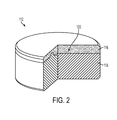
- FIG. 2 is a perspective partial cross-sectional view of a cutting element of the earth-boring tool of FIG. 1 ;
- FIG. 3 is a perspective view of a substrate of the cutting element of FIG. 2 ;
- FIG. 4 is an end view of the substrate of the cutting element of FIG. 2 ;
- FIG. 5 is a perspective view of another embodiment of a substrate for a cutting element
- FIG. 6 is an end view of the substrate of FIG. 5 ;
- FIG. 7 is a perspective view of another embodiment of a substrate for a cutting element
- FIG. 8 is an end view of the substrate of FIG. 7 ;
- FIG. 9 is a perspective view of another embodiment of a substrate for a cutting element.
- FIG. 10 is an end view of the substrate of FIG. 9 ;
- FIG. 11 is a perspective view of another embodiment of a substrate for a cutting element
- FIG. 12 is an end view of the substrate of FIG. 11 ;
- FIG. 13 is a perspective view of another embodiment of a substrate for a cutting element
- FIG. 14 is an end view of the substrate of FIG. 13 ;
- FIG. 15 is a cross-sectional view of a container in a first stage of a process for forming a cutting element
- FIG. 16 is a cross-sectional view of the container of FIG. 15 in a second stage of a process for forming a cutting element.
- Disclosed embodiments relate generally to non-planar interfaces between polycrystalline tables and substrates of cutting elements for earth-boring tools that may manage stress in regions of the polycrystalline table and interrupt crack propagation through the polycrystalline table. More specifically, disclosed are embodiments of non-planar interfaces that may strengthen high-stress regions within the polycrystalline table, interrupt crack propagation tending to extend circumferentially around the polycrystalline table, and reduce stress concentrations associated with conventional non-planar interface designs.
- earth-boring tool means and includes any type of bit or tool used for removing earth material during the formation or enlargement of a wellbore in a subterranean formation.
- earth-boring tools include fixed-cutter bits, rolling cone bits, impregnated bits, percussion bits, core bits, eccentric bits, bicenter bits, mills, reamers, drag bits, hybrid bits, and other drilling bits and tools known in the art.
- polycrystalline table and “polycrystalline material” mean and include any structure or material comprising grains (e.g., crystals) of a material (e.g., a superabrasive material) that are bonded directly together by inter-granular bonds.
- the crystal structures of the individual grains of the material may be randomly oriented in space within the polycrystalline table.
- polycrystalline tables include polycrystalline diamond compacts (PDCs) characterized by diamond grains that are directly bonded to one another to form a matrix of diamond material with interstitial spaces among the diamond grains.
- inter-granular bond and “interbonded” mean and include any direct atomic bond (e.g., covalent, metallic, etc.) between atoms in adjacent grains of superabrasive material.
- superhard means and includes any material having a Knoop hardness value of about 3,000 Kg f /mm 2 (29,420 MPa) or more.
- Superhard materials include, for example, diamond and cubic boron nitride. Superhard materials may also be characterized as “superabrasive” materials.
- substantially completely removed when used in connection with removal of catalyst material from a polycrystalline material means and includes removal of all catalyst material accessible by known catalyst removal processes.
- substantially completely removing catalyst material includes leaching catalyst material from all accessible interstitial spaces of a polycrystalline material by immersing the polycrystalline material in a leaching agent (e.g., aqua regia) and permitting the leaching agent to flow through the network of interconnected interstitial spaces until all accessible catalyst material has been removed. Residual catalyst material located in isolated interstitial spaces, which are not connected to the rest of the network of interstitial spaces and are not accessible without damaging or otherwise altering the polycrystalline material, may remain.
- a leaching agent e.g., aqua regia
- L-shaped means and includes any shape defined by two rays extending from an intersection, wherein an angle defined by the rays is between 80° and 100°.
- L-shapes include right angles, T-squares, perpendicular rays, and other known L-shapes.
- the earth-boring tool 100 may include a body 102 .
- An upper end 104 of the body 102 may include a connector 106 (e.g., an American Petroleum Institute (API) threaded connection) configured to connect the earth-boring tool 100 to other components of a drill string (e.g., drill pipe).
- a lower end 108 of the body 102 may be configured to engage with an underlying earth formation.
- the lower end 108 of the body 102 may include blades 110 extending outward from a remainder of the body 102 and extending radially over the lower end 108 of the body 102 .
- Cutting elements 112 may be secured to the blades 110 , such as, for example, by brazing the cutting elements 112 within pockets 114 formed in the blades 110 , at rotationally leading faces of the blades 110 .
- the cutting elements 112 and blades 110 may cooperatively define a cutting structure configured to engage with and remove an underlying earth formation.
- the cutting element 112 may include a polycrystalline table 116 of a superhard material configured to directly contact and remove earth material.
- the polycrystalline table 116 may comprise a generally disk-shaped structure formed from individual grains of superhard material that have interbonded to form a polycrystalline matrix of grains with interstitial spaces located among the grains.
- the superhard material may comprise, for example, diamond or cubic boron nitride.
- the polycrystalline table 116 may be positioned on an end of a substrate 118 and secured to the substrate 118 .
- the substrate 118 may comprise a hard material suitable for use in earth-boring applications such as, for example, a ceramic-metallic composite material (i.e., a cermet) (e.g., cemented tungsten carbide), and may be formed in a generally cylindrical shape.
- the polycrystalline table 116 may be secured to the substrate 118 by, for example, a continuous metal material extending into the polycrystalline table 116 and the substrate 118 , such as, for example, matrix material of the substrate 118 that has infiltrated among and extends continuously into the interstitial spaces of the polycrystalline table 116 .
- An interface 120 between the polycrystalline table 116 and the substrate 118 , defined by their abutting surfaces, may be non-planar.
- the non-planar interface 120 of the cutting element 112 may be configured to strengthen high-stress regions within the polycrystalline table 116 , interrupt crack propagation tending to extend circumferentially around the polycrystalline table 116 , and reduce stress concentrations associated with conventional non-planar interface designs.
- FIGS. 3 and 4 a perspective view and an end view of the substrate 118 of the cutting element 112 of FIG. 2 are shown.
- An end 122 of the substrate 118 on which the polycrystalline table 116 (see FIG. 2 ) will be formed or otherwise attached may be non-planar.
- the non-planar end 122 of the substrate 118 may include a cross-shaped (e.g., cruciform) feature 124 , which is depicted as a cross-shaped groove extending into the substrate 118 in the embodiment of FIGS. 3 and 4 .
- the non-planar end 122 of the substrate 118 may comprise a cross-shaped protrusion extending away from a remainder of the substrate 118 .
- a mating cross-shaped feature embodied as the other of a groove or a protrusion, may be located on the polycrystalline table 116 (see FIG. 2 ).
- a center point 126 of the cross-shaped feature 124 defined at an intersection of perpendicular centerlines 128 of individual radially extending features 130 (e.g., grooves or protrusions) may be located at a central axis 132 of the substrate 118 .
- the individual radially extending features 130 may extend to the periphery of the substrate 118 , such that the planar surface 134 at the periphery is interrupted by the cross-shaped feature 124 .
- a depth D of the cross-shaped feature 124 may be, for example, between about 0.25 mm and about 0.50 mm. As a specific, non-limiting example, the depth D of the cross-shaped feature 124 may be about 0.40 mm. The depth D of the cross-shaped feature 124 may be uniform in some embodiments. In other embodiments, the depth D of the cross-shaped feature 124 may not be constant.
- the depth D of the cross-shaped feature may change (e.g., increase or decrease) as distance from the central axis 132 increases, which change may be constant (e.g., linear) or may vary (e.g., exponentially).
- a width W CSF of each individual radially extending feature 130 of the cross-shaped feature 124 may be, for example, between about 0.75 mm and about 1.75 mm.
- the width W CSF of each individual radially extending feature of the cross-shaped feature 124 may be about 1.25 mm.
- the width W CSF of each individual radially extending feature 130 of the cross-shaped feature 124 may be uniform in some embodiments.
- the width W CSF of each individual radially extending feature 130 of the cross-shaped feature 124 may not be constant.
- width W CSF of each individual radially extending feature 130 of the cross-shaped feature 124 may change (e.g., increase or decrease) as distance from the central axis 132 increases, which change may be constant (e.g., linear) or may vary (e.g., exponentially).
- the cross-shaped feature 124 comprises a cross-shaped groove extending into the substrate 118
- the cross-shaped feature may strengthen the polycrystalline table 116 (see FIG. 2 ) in regions where the polycrystalline table 116 (see FIG.
- the cross-shaped feature 124 may act as a conduit to channel stress away from the peripheral edge.
- the non-planar end 122 of the substrate 118 may include L-shaped features 136 located proximate corners of the cross-shaped feature 124 in each quadrant defined by the cross-shaped feature 124 , which L-shaped features 136 are depicted as L-shaped protrusions extending away from the remainder of the substrate 118 in the embodiment of FIGS. 3 and 4 .
- the non-planar end 122 of the substrate 118 may comprise L-shaped grooves extending into the substrate 118 .
- a mating L-shaped feature, embodied as the other of a groove or a protrusion, may be located on the polycrystalline table 116 (see FIG. 2 ). Arms 138 of the L-shaped features 136 may not extend to the periphery of the substrate 118 such that a portion of the planar surface 134 at the periphery is uninterrupted by the L-shaped features 136 .
- a height H of each L-shaped feature 136 may be greater than the greatest depth D of the cross-shaped feature 124 .
- the height H of each L-shaped feature 136 may be at least about 2 times, at least about 3 times, or even at least about 4 times greater than the greatest depth D of the cross-shaped feature 124 .
- the height H of each L-shaped feature 136 may be, for example, between about 1.50 mm and about 0.50 mm. As a specific, non-limiting example, the height H of each L-shaped feature 136 may be about 1.27 mm.
- a width W LSF of each arm 138 of the L-shaped features 136 may be greater than or equal to the greatest width W CSF of each radially extending feature 130 of the cross-shaped feature 124 .
- the width W LSF of each arm 138 of the L-shaped features 136 may be at least about 1.25 times, at least about 1.5 times, or even at least about 1.75 times greater than the greatest width W CSF of each radially extending feature 130 of the cross-shaped feature 124 .
- the width W LSF of each arm 138 of the L-shaped features 136 may be, for example, between about 1.00 mm and about 3.00 mm.
- the width W LSF of each arm 138 of the L-shaped features 136 may be about 2.00 mm.
- each L-shaped feature 136 comprises an L-shaped protrusion extending away from the remainder of the substrate 118
- the L-shaped feature 136 may strategically weaken regions where the polycrystalline table 116 (see FIG. 2 ) is not particularly susceptible to damage, such as, for example, in intermediate regions between the periphery and center of the cutting element 112 (see FIG. 2 ), by thinning the polycrystalline table 116 (see FIG. 2 ) at those locations.
- the L-shaped features 136 may interrupt crack propagation through the polycrystalline table 116 (see FIG. 2 ) such that the likelihood that cracks propagate to complete an entire circle within the polycrystalline table 116 (see FIG. 2 ) may be reduced, which may reduce the occurrence of spalling of the polycrystalline table 116 (see FIG. 2 ).
- Transitions between surfaces defining the non-planar end 122 of the substrate 118 may be rounded.
- a radius of curvature of each transition between surfaces defining the non-planar end 122 may be about 0.5 times the depth D of the cross-shaped feature 124 or greater. More specifically, the radius of curvature of each transition between surfaces defining the non-planar end 122 may be at least about 0.75 times the depth D of the cross-shaped feature 124 , at least equal to the depth D of the cross-shaped feature 124 , or at least 1.25 times the depth D of the cross-shaped feature 124 .
- the radius of curvature of each transition between surfaces defining the non-planar end 122 may be, for example, at least about 0.25 mm.
- radiuses of curvature of each transition between surfaces defining the non-planar end 122 may be about 0.6 mm.
- different transitions between different surfaces defining the non-planar end 122 e.g., between the planar surface 134 and the L-shaped features 136 , and between the L-shaped features 136 and the cross-shaped feature 124 , between surfaces of each individual L-shaped feature 136 or of each cross-shaped feature 124
- each transition may have the same radius of curvature.
- the location at which one feature 124 or 136 ends and another 124 or 136 begins may not be readily visible. Accordingly, the height H, depth D, and widths W CSF and W LSF described previously herein are to be measured from a point where the feature 124 or 136 intersects with the elevation of the planar surface 134 . By making all transitions rounded, the non-planar interface 120 (see FIG. 2 ) may exhibit reduced stress concentrations as compared to conventional non-planar interfaces.
- the non-planar end 122 of the substrate 118 may include all the features 124 and 136 described previously in connection with FIGS. 3 and 4 .
- the non-planar end 122 may include a curved feature 140 in each quadrant defined by the L-shaped features 136 .
- the curved feature 140 is depicted as a curved protrusion extending from a remainder of the substrate 118 in the embodiment of FIGS. 5 and 6 .
- the curved feature 140 may be a curved groove extending into the substrate 118 .
- a mating curved feature embodied as the other of a groove or a protrusion, may be located on the polycrystalline table 116 (see FIG. 2 ).
- the curved feature 140 may extend between the arms 138 of each of the L-shaped features 136 , with a center of curvature of each curved feature 140 being located at the central axis 132 of the substrate 118 , which may also define the central axis of the cutting element 112 (see FIG. 2 ). None of the curved features 140 may intersect with the arms 138 of the L-shaped features 136 , such that a portion of the planar surface 134 may be interposed between each curved feature 140 and adjacent arms 138 of the L-shaped features 136 .
- each curved feature 140 may be located at the same radial position of, or radially closer to the central axis 132 than, radially outermost portions of the L-shaped features 136 .
- a circle defined by connecting radially outermost points of the arms 138 of each L-shaped feature 136 may also define an outermost extent of each curved feature 140 .
- a width W CF of each curved feature 140 may be less than or equal to the greatest width W CSF of the radially extending features 130 of the cross-shaped feature 124 .
- the width W CF of each curved feature 136 may be about 1.0 time or less, about 0.75 times or less, or about 0.5 times or less than the greatest width W CSF of the radially extending features 130 of the cross-shaped feature 124 .
- the width W CF of each curved feature 140 may be, for example, between about 1.25 mm and about 0.50 mm. As a specific, non-limiting example, the width W CF of each curved feature 136 may be about 0.75 mm.
- a height H CF of each curved feature 140 may be less than or equal to the height H of each L-shaped feature 136 .
- the height H CF of each curved feature 140 may be about 1.0 time or less, about 0.75 times or less, or about 0.50 times or less than the height H of each L-shaped feature 136 .
- the height H CF of each curved feature 140 may be, for example, between about 1.25 mm and about 0.50 mm. As a specific, non-limiting example, the height H CF of each curved feature 140 may be about 1.00 mm.
- the curved features 140 may interrupt crack propagation within the polycrystalline table 116 (see FIG. 2 ) and strategically weaken the polycrystalline table 116 (see FIG. 2 ) to channel stress away from critical regions of the polycrystalline table 116 (see FIG. 2 ), such as, for example, the peripheral edge.
- FIGS. 7 and 8 a perspective view and an end view of another embodiment of a substrate 118 for a cutting element 112 (see FIG. 2 ) are shown.
- the non-planar end 122 of the substrate 118 may include all the features 124 , 136 , and 140 described previously in connection with FIGS. 5 and 6 .
- the non-planar end 122 may include a trench 142 formed in each curved feature 140 .
- the trench 142 is depicted as a extending into the substrate 118 in the embodiment of FIGS. 5 and 6 . In other embodiments, the trench 142 extend away from the substrate 118 .
- a mating trench embodied as the other of a extending away from or into the polycrystalline table 116 (see FIG. 2 ), may be located on the polycrystalline table 116 (see FIG. 2 ).
- Each trench 142 may extend for an entire length of each curved feature 140 , with each trench 142 following the curve of an associated curved feature 140 .
- a center of curvature of each trench 142 may be located at the central axis 132 of the substrate 118 , which may also define the central axis of the cutting element 112 (see FIG. 2 ).
- Each trench 142 may be centrally located on its associated curved feature 140 , such that the curved feature 140 extends radially an equal distance from each of the radially innermost and radially outermost portion of the trench 142 .
- a width W T of each trench 142 may be less than the width W CF of its associated curved feature 140 .
- the width W T of each trench 142 may be about 0.5 times or less, about 0.25 times or less, or about 0.125 times or less than the width W CF of its associated curved feature 140 .
- the width W T of each trench 142 may be, for example, between about 0.75 mm and about 0.12 mm. As a specific, non-limiting example, the width W T of each trench 142 may be about 0.25 mm.
- a depth D T of each trench 142 as measured from an uppermost point on its associated curved feature 140 extending into or away from the curved feature 140 , may be less than or equal to the height H CF of the associated curved feature 140 .
- the depth D T of each trench 142 may be about 0.75 times or less, or about 0.50 times or less, or about 0.25 times or less than the height H CF of each associated curved feature 140 .
- the depth D T of each curved feature 140 may be, for example, between about 0.75 mm and about 0.25 mm.
- the depth D T of each trench 142 may be about 0.50 mm.
- the trenches 142 may interrupt crack propagation within the polycrystalline table 116 (see FIG. 2 ) and channel stress away from critical regions of the polycrystalline table 116 (see FIG. 2 ), such as, for example, the peripheral edge.
- the non-planar end 122 of the substrate 118 may include all the features 124 and 136 described previously in connection with FIGS. 3 and 4 .
- the non-planar end 122 may include a tapered surface 144 in an area between the arms 138 of each of the L-shaped features 136 , extending from an intersect point 146 of each of the L-shaped features toward the one of the substrate 118 and the polycrystalline table 116 (see FIG. 2 ).
- the tapered surface 144 is depicted as extending from an intersect point 146 positioned at the radially outermost location of intersection of the two arms 138 at maximum height H above the planar surface 134 toward the remainder of the substrate 118 .
- the tapered surface 144 may extend toward the polycrystalline table 116 and may extend from an intersect point defined by other features of the arms 138 (e.g., centerlines, radially innermost portion at maximum height H, midway to maximum height H, etc.).
- the tapered surface 144 may intersect with the arms 138 of the L-shaped features 136 along their length, such that no portion of the planar surface 134 is interposed between each tapered surface 144 and adjacent arms 138 of the L-shaped features 136 and the gradual taper of the tapered surface 144 is visible as compared to a more abrupt transition to the maximum height H of each L-shaped feature 136 .
- Radially outermost portions of each tapered surface may be located at the same radial position of, or radially closer to the central axis 132 than, radially outermost portions of the L-shaped features 136 .
- a circle defined by connecting radially outermost points of the arms 138 of each L-shaped feature 136 may also define an outermost extent of each tapered surface 144 .
- a slope of each tapered surface 144 may be less than or equal to the height H of each L-shaped feature 136 divided by the length of an arm 138 of each L-shaped feature.
- the slope of each tapered surface 144 may be less than or equal to the height H of each L-shaped feature 136 divided by the length of an arm 138 as measured from a radially outermost point of the arm 138 at an elevation of the planar surface 134 to a radially innermost point of the arm 138 at the elevation of the planar surface 134 .
- the slope of each tapered surface 144 may be, for example, between about 0.50 and about 0.10. As a specific, non-limiting example, the slope of each tapered surface 144 may be about 0.30.
- the sloped surfaces 144 may strategically weaken the polycrystalline table 116 (see FIG. 2 ) to channel stress away from critical regions of the polycrystalline table 116 (see FIG. 2 ), such as, for example, the peripheral edge.
- the non-planar end 122 of the substrate 118 may include all the features 124 , 136 , and 140 described previously in connection with FIGS. 9 and 10 .
- the non-planar end 122 may include a pear-shaped feature 148 in each quadrant defined by the L-shaped features 136 .
- the pear-shaped feature 148 is depicted as a pear-shaped protrusion extending from the tapered surface 144 in the embodiment of FIGS. 11 and 12 .
- the curved feature 140 may be a pear-shaped depression extending into the tapered surface 144 .
- a mating pear-shaped feature embodied as the other of a depression or a protrusion, may be located on the polycrystalline table 116 (see FIG. 2 ).
- An axis of symmetry 150 of each pear-shaped feature 148 may bisect an angle ⁇ defined between the arms 138 of each of the L-shaped features 136 . Radially outermost portions of each pear-shaped feature 148 may be located radially closer to the central axis 132 than radially outermost portions of the tapered surface 144 .
- each pear-shaped feature 148 and the intersect point 146 described previously in connection with FIGS. 9 and 10 may be equal to the shortest distance between a radially outermost portion of each pear-shaped feature 148 and the radially outermost portion of the tapered surface 144 .
- a greatest width W PSF of each pear-shaped feature 148 taken in a direction perpendicular to the axis of symmetry 150 of a respective pear-shaped feature 148 may be less than or equal to the greatest width W CSF of the radially extending features 130 of the cross-shaped feature 124 .
- the greatest width W PSF of each pear-shaped feature 148 may be about 1.0 time or less, about 0.75 times or less, or about 0.5 times or less than the greatest width W CSF of the radially extending features 130 of the cross-shaped feature 124 .
- the greatest width W PSF of each pear-shaped feature 148 may be, for example, between about 1.25 mm and about 0.50 mm.
- the greatest width W PSF of each pear-shaped feature 148 may be about 0.75 mm.
- a length L CF of each pear-shaped feature 148 taken in a direction parallel to the axis of symmetry 150 of a respective pear-shaped feature 148 may be greater than or equal to the greatest width W PSF of the pear-shaped feature 148 .
- a length L PSF of each pear-shaped feature 148 may be about 1.0 time or greater, about 1.1 times the greater, or about 1.25 times or greater than the greatest width W PSF of the pear-shaped feature 148 .
- the length L PSF of each pear-shaped feature 148 may be, for example, between about 1.50 mm and about 0.50 mm.
- the length L PSF of each pear-shaped feature 148 may be about 1.00 mm.
- a height H PSF of each pear-shaped feature 148 as measured from the planar surface 134 at the periphery of the end 122 of the substrate 118 extending into the substrate 118 or into the polycrystalline table 116 (see FIG. 2 ), may be less than or equal to the height H of each L-shaped feature 136 .
- the height H PSF of each pear-shaped feature 148 may be about 1.0 time or less, about 0.75 times or less, or about 0.50 times or less than the height H of each L-shaped feature 136 .
- the height H PSF of each curved feature 148 may be, for example, between about 1.25 mm and about 0.50 mm. As a specific, non-limiting example, the height H PSF of each curved feature 148 may be about 1.00 mm.
- the pear-shaped features 148 may interrupt crack propagation within the polycrystalline table 116 (see FIG. 2 ) and strategically weaken the polycrystalline table 116 (see FIG. 2 ) to channel stress away from critical regions of the polycrystalline table 116 (see FIG. 2 ), such as, for example, the peripheral edge.
- FIGS. 13 and 14 a perspective view and an end view of another embodiment of a substrate 118 for a cutting element 112 are shown.
- the non-planar end 122 of the substrate 118 may include all the features 124 , 136 , and 140 described previously in connection with FIGS. 9 and 10 .
- the non-planar end 122 may include concentric arcs 152 in each quadrant defined by the L-shaped features 136 .
- the concentric arcs 152 are depicted as concentric arc-shaped protrusions extending from the tapered surface 144 in the embodiment of FIGS. 13 and 14 .
- the concentric arcs 152 may be a concentric arc-shaped grooves extending into the tapered surface 144 .
- Mating concentric arcs embodied as the other of a groove or a protrusion, may be located on the polycrystalline table 116 (see FIG. 2 ).
- the concentric arcs 152 may extend between the arms 138 of each of the L-shaped features 136 , with a center of curvature of each concentric arc 152 being located at the central axis 132 of the substrate 118 , which may also define the central axis of the cutting element 112 (see FIG. 2 ).
- None of the concentric arcs 152 may intersect with the arms 138 of the L-shaped features 136 , such that a portion of the tapered surface 144 may be interposed between each concentric arc 152 and adjacent arms 138 of the L-shaped features 136 .
- Radially outermost portions of radially outermost concentric arcs 152 may be located radially closer to the central axis 132 than radially outermost portions of the L-shaped features 136 .
- a circle defined by connecting radially outermost points of the arms 138 of each L-shaped feature 136 may be located radially outward from the radially outermost portions of radially outermost concentric arcs 152 .
- a width W CA of each concentric arc 152 may be less than the greatest width W CSF of the radially extending features 130 of the cross-shaped feature 124 .
- the width W CA of each concentric arc 152 may be about 0.50 times or less, about 0.25 times or less, or about 0.125 times or less than the greatest width W CSF of the radially extending features 130 of the cross-shaped feature 124 .
- the width W CA of each concentric arc may be, for example, between about 0.75 mm and about 0.10 mm.
- the width W CA of each concentric arc 152 may be about 0.25 mm.
- a height H CA of each concentric arc 152 may be sufficiently small that the concentric arcs 152 do not extend above any L-shaped feature 136 .
- the height H CA of each concentric arc 152 may be between about 0.50 mm and about 0.10 mm.
- the height H CA of each concentric arc 152 may be about 0.25 mm.
- a distance D between adjacent concentric arcs 152 may be greater than or equal to the height H CA of each concentric arc 152 .
- the distance D between adjacent concentric arcs 152 may be 1.0 times or greater, 1.25 times or greater, or 1.5 times or greater than the height HCA of each concentric arc 152 .
- the distance D between adjacent concentric arcs 152 may be, for example, between about 0.75 mm and about 0.25 mm. As a specific, non-limiting example, the distance D between adjacent concentric arcs 152 may be about 0.50 mm.
- a number of arcs may be between about three and about six. For example, the number of arcs may be about four.
- the concentric arcs 152 may interrupt crack propagation within the polycrystalline table 116 (see FIG. 2 ) and strategically weaken the polycrystalline table 116 (see FIG. 2 ) to channel stress away from critical regions of the polycrystalline table 116 (see FIG. 2 ), such as, for example, the peripheral edge.
- the polycrystalline table 116 may be formed by subjecting particles of superhard material to a high temperature/high pressure (HTHP) process, sintering the particles to one another to form the polycrystalline material of the polycrystalline table 116 (see FIG. 2 ).
- HTHP high temperature/high pressure
- Such a process may be performed by placing a container in which the particles are located into a press and subjecting the particles to the HTHP process.
- the HTHP process may also be used to attach the polycrystalline table 116 to a substrate 118 to form a cutting element 112 (see FIG. 2 ).
- FIG. 2 a cross-sectional view of such a container 154 for forming a cutting element 112 (see FIG. 2 ) is shown in FIG.
- the container 154 may include one or more generally cup-shaped members, such as cup-shaped member 156 c , which may act as a receptacle. Particles 158 may be placed in the cup-shaped member 156 c , which may have a circular end wall and a generally cylindrical lateral side wall extending perpendicularly from the circular end wall, such that the cup-shaped member 156 c is generally cylindrical and includes a first closed end and a second, opposite open end.
- the particles 158 may include a superhard material in the form of, for example, powdered diamond (e.g., natural, synthetic, or natural and synthetic diamond) or powdered cubic boron nitride, which may optionally be mixed with a liquid (e.g., alcohol) to form a slurry (e.g., a paste).
- the particles 158 may include a catalyst material (e.g., iron, nickel, or cobalt) selected to catalyze formation of inter-granular bonds between individual particles of the superhard material in some embodiments.
- the particles 158 may exhibit a monomodal or multimodal (e.g., bimodal, trimodal, etc.) particle size distribution.
- FIG. 16 a cross-sectional view of the container 154 ′ of FIG. 15 is shown in a second stage of a process for forming a cutting element 112 (see FIG. 2 ).
- the container 154 ′ may include the cup-shaped member 156 c and two additional cup-shaped members 156 a and 156 b , which may be assembled and swaged and/or welded together to form the container 154 ′.
- a substrate 118 having a non-planar end 122 such as, for example, any of those shown in FIGS. 3 through 14 , may be placed in the container 154 ′ with the non-planar end 122 facing the particles 158 .
- the substrate 118 may be in a green state (i.e., an unsintered state with less than a final density) with hard particles (e.g., tungsten carbide) held in place by a binder material (e.g., wax).
- the substrate may be in a brown state (i.e., a sintered state still with less than a final density) with hard particles bound in a matrix material (e.g., a solvent metal catalyst).
- the substrate 118 may be a fully sintered part (e.g., cemented tungsten carbide at a final density).
- the non-planar end 122 may be pressed against the particles 158 to impart a shape inverse to the shape of the non-planar end 122 to the particles 158 .
- the substrate 118 may be placed in the container 154 ′ before the particles 158 , and the particles 158 may simply conform to the shape of the non-planar end 122 when they are placed adjacent the non-planar end 122 within the container 154 ′.
- Assembly of the container 154 ′ may be completed, and the substrate 118 and particles 158 may be subjected to a high temperature/high pressure (HTHP) process to cause the particles 158 to interbond with one another in the presence of catalyst material (e.g., melted to flow among the rest of the particles 158 or swept among the particles 158 from within the substrate 118 ) to form the polycrystalline table 116 and to secure the polycrystalline table 116 to the substrate 118 at the non-planar interface 120 .
- the HTHP process may also sinter the substrate 118 to a final density. Conventional HTHP processing may be used to form the cutting element 112 (see FIG. 2 ).
- a cutting element for an earth-boring tool comprises a substrate, a polycrystalline table comprising superhard material secured to the substrate at an end of the substrate, and a non-planar interface defined between the polycrystalline table and the substrate.
- the non-planar interface comprises a cross-shaped groove extending into one of the substrate and the polycrystalline table and L-shaped grooves extending into the other of the substrate and the polycrystalline table proximate corners of the cross-shaped groove. Transitions between surfaces defining the non-planar interface are rounded.
- the cutting element of Embodiment 1 further comprising a tapered surface in an area between arms of each of the L-shaped grooves, the tapered surface extending from an intersect point of each of the L-shaped grooves toward the one of the substrate and the polycrystalline table.
- the cutting element of Embodiment 2 further comprising concentric grooves extending from each tapered surface into the other of the substrate and the polycrystalline table, wherein the concentric grooves do not intersect with the arms of the L-shaped grooves and a center of curvature of each of the concentric grooves is located at a central axis of the cutting element.
- the cutting element of Embodiment 2 further comprising a pear-shaped depression extending from each tapered surface into the other of the substrate and the polycrystalline table, wherein an axis of symmetry of the pear-shaped depression bisects an angle defined between the arms of each of the L-shaped grooves.
- the cutting element of Embodiment 1 further comprising a curved groove extending between arms of each of the L-shaped grooves into the other of the substrate and the polycrystalline table, wherein a center of curvature of each curved groove is located at a central axis of the cutting element and wherein the curved grooves do not intersect with the arms of the L-shaped grooves.
- An earth-boring tool comprises a body and cutting elements secured to the body. At least one of the cutting elements comprises a substrate, a polycrystalline table comprising superhard material secured to the substrate at an end of the substrate, and a non-planar interface defined between the polycrystalline table and the substrate.
- the non-planar interface comprises a cross-shaped groove extending into one of the substrate and the polycrystalline table and L-shaped grooves extending into the other of the substrate and the polycrystalline table proximate corners of the cross-shaped groove. Transitions between surfaces defining the non-planar interface are rounded.
- a method of forming a cutting element for an earth-boring tool comprises forming a substrate to have a non-planar end.
- the non-planar end comprises a cross-shaped groove extending into the substrate and L-shaped protrusions extending from a remainder of the substrate proximate corners of the cross-shaped groove. Transitions between surfaces defining the non-planar end are shaped to be rounded.
- Particles of superhard material are positioned adjacent the non-planar end of the substrate in a container. The particles are sintered in a presence of a catalyst material to form a polycrystalline table secured to the substrate, with a non-planar interface being defined between the substrate and the polycrystalline table.
- Embodiment 12 further comprising forming the non-planar end to comprise a tapered surface in an area between arms of each of the L-shaped grooves, the tapered surface extending from an intersect point of each of the L-shaped grooves toward the remainder of the substrate.
- Embodiment 13 further comprising forming the non-planar end to comprise concentric protrusions extending from each tapered surface away from the remainder of the substrate, wherein the concentric protrusions do not intersect with the arms of the L-shaped protrusions and a center of curvature of each of the concentric protrusions is located at a central axis of the substrate.
- Embodiment 13 further comprising forming the non-planar end to comprise a pear-shaped protrusion extending from each tapered surface away from the remainder of the substrate, wherein an axis of symmetry of the pear-shaped protrusion bisects an angle defined between the arms of each of the L-shaped protrusions.
- Embodiment 12 further comprising forming the non-planar end to comprise a curved protrusion extending between arms of each of the L-shaped protrusions into the substrate, wherein a center of curvature of each curved protrusion is located at a central axis of the substrate and wherein the curved protrusions do not intersect with the arms of the L-shaped protrusions.
- Embodiment 16 or Embodiment 17 further comprising forming the non-planar end to comprise a trench extending toward the substrate formed in each curved protrusion, wherein the trench follows the curve of each curved protrusion.
Abstract
Description
Claims (20)
Priority Applications (2)
| Application Number | Priority Date | Filing Date | Title |
|---|---|---|---|
| US13/780,698 US9140072B2 (en) | 2013-02-28 | 2013-02-28 | Cutting elements including non-planar interfaces, earth-boring tools including such cutting elements, and methods of forming cutting elements |
| PCT/US2014/019240 WO2014134390A1 (en) | 2013-02-28 | 2014-02-28 | Cutting elements including non-planar interfaces, earth-boring tools including such cutting elements, and methods of forming cutting elements |
Applications Claiming Priority (1)
| Application Number | Priority Date | Filing Date | Title |
|---|---|---|---|
| US13/780,698 US9140072B2 (en) | 2013-02-28 | 2013-02-28 | Cutting elements including non-planar interfaces, earth-boring tools including such cutting elements, and methods of forming cutting elements |
Publications (2)
| Publication Number | Publication Date |
|---|---|
| US20140238753A1 US20140238753A1 (en) | 2014-08-28 |
| US9140072B2 true US9140072B2 (en) | 2015-09-22 |
Family
ID=51387004
Family Applications (1)
| Application Number | Title | Priority Date | Filing Date |
|---|---|---|---|
| US13/780,698 Active 2033-06-07 US9140072B2 (en) | 2013-02-28 | 2013-02-28 | Cutting elements including non-planar interfaces, earth-boring tools including such cutting elements, and methods of forming cutting elements |
Country Status (2)
| Country | Link |
|---|---|
| US (1) | US9140072B2 (en) |
| WO (1) | WO2014134390A1 (en) |
Cited By (4)
| Publication number | Priority date | Publication date | Assignee | Title |
|---|---|---|---|---|
| US20190106943A1 (en) * | 2017-10-10 | 2019-04-11 | Varel International Ind., L.L.C. | Drill bit having shaped impregnated shock studs and/or intermediate shaped cutter |
| USD875147S1 (en) * | 2018-05-10 | 2020-02-11 | Seed Technologies Corp., Ltd. | Drill bit |
| US11035177B2 (en) * | 2019-01-16 | 2021-06-15 | Ulterra Drilling Technologies L.P. | Shaped cutters |
| US11255129B2 (en) * | 2019-01-16 | 2022-02-22 | Ulterra Drilling Technologies, L.P. | Shaped cutters |
Families Citing this family (14)
| Publication number | Priority date | Publication date | Assignee | Title |
|---|---|---|---|---|
| CN102933785B (en) | 2010-04-23 | 2016-01-13 | 贝克休斯公司 | The cutting element of earth-boring tools, comprise the earth-boring tools of this cutting element with and related methods |
| US9103174B2 (en) | 2011-04-22 | 2015-08-11 | Baker Hughes Incorporated | Cutting elements for earth-boring tools, earth-boring tools including such cutting elements and related methods |
| US8991525B2 (en) | 2012-05-01 | 2015-03-31 | Baker Hughes Incorporated | Earth-boring tools having cutting elements with cutting faces exhibiting multiple coefficients of friction, and related methods |
| US9428966B2 (en) | 2012-05-01 | 2016-08-30 | Baker Hughes Incorporated | Cutting elements for earth-boring tools, earth-boring tools including such cutting elements, and related methods |
| US9243452B2 (en) | 2011-04-22 | 2016-01-26 | Baker Hughes Incorporated | Cutting elements for earth-boring tools, earth-boring tools including such cutting elements, and related methods |
| US9650837B2 (en) | 2011-04-22 | 2017-05-16 | Baker Hughes Incorporated | Multi-chamfer cutting elements having a shaped cutting face and earth-boring tools including such cutting elements |
| US9482057B2 (en) | 2011-09-16 | 2016-11-01 | Baker Hughes Incorporated | Cutting elements for earth-boring tools, earth-boring tools including such cutting elements and related methods |
| CN106068362A (en) * | 2013-12-17 | 2016-11-02 | 第六元素有限公司 | Superhard component and manufacture method thereof |
| US10465447B2 (en) | 2015-03-12 | 2019-11-05 | Baker Hughes, A Ge Company, Llc | Cutting elements configured to mitigate diamond table failure, earth-boring tools including such cutting elements, and related methods |
| CN108431361B (en) * | 2015-12-14 | 2022-05-03 | 史密斯国际有限公司 | Direct casting of superhard inserts in bit bodies |
| US10400517B2 (en) | 2017-05-02 | 2019-09-03 | Baker Hughes, A Ge Company, Llc | Cutting elements configured to reduce impact damage and related tools and methods |
| US10570668B2 (en) | 2018-07-27 | 2020-02-25 | Baker Hughes, A Ge Company, Llc | Cutting elements configured to reduce impact damage and mitigate polycrystalline, superabrasive material failure earth-boring tools including such cutting elements, and related methods |
| US10577870B2 (en) | 2018-07-27 | 2020-03-03 | Baker Hughes, A Ge Company, Llc | Cutting elements configured to reduce impact damage related tools and methods—alternate configurations |
| US11920409B2 (en) | 2022-07-05 | 2024-03-05 | Baker Hughes Oilfield Operations Llc | Cutting elements, earth-boring tools including the cutting elements, and methods of forming the earth-boring tools |
Citations (357)
| Publication number | Priority date | Publication date | Assignee | Title |
|---|---|---|---|---|
| US734515A (en) | 1902-07-26 | 1903-07-28 | Horatio Collins | Rock-drill bit. |
| US1650492A (en) | 1926-01-05 | 1927-11-22 | Coaton Arthur Allan | Rock-drill bit |
| US2641446A (en) | 1948-02-28 | 1953-06-09 | Sandvikens Jernverks Aktiehola | Bore crown for percussion drilling |
| US2707897A (en) | 1948-05-04 | 1955-05-10 | William Douglas Sellers | Expanding, undercutting insert |
| US2735656A (en) | 1956-02-21 | Rock drilling bit | ||
| US2777672A (en) | 1949-03-26 | 1957-01-15 | Sandvikens Jernverke Aktiebola | Percussion drilling bit |
| US2842342A (en) | 1955-07-06 | 1958-07-08 | Sandvikens Jernverks Ab | Rock drill cutting insert of hard metal |
| US2888247A (en) | 1955-12-13 | 1959-05-26 | Sandvikens Jernverks Ab | Rock drill cutting insert of sintered hard metal |
| US3388757A (en) | 1967-03-23 | 1968-06-18 | Smith Ind International Inc | Hardened inserts for drill bits |
| US3745623A (en) | 1971-12-27 | 1973-07-17 | Gen Electric | Diamond tools for machining |
| US3913280A (en) | 1971-01-29 | 1975-10-21 | Megadiamond Corp | Polycrystalline diamond composites |
| US4148368A (en) | 1976-09-27 | 1979-04-10 | Smith International, Inc. | Rock bit with wear resistant inserts |
| US4200159A (en) | 1977-04-30 | 1980-04-29 | Christensen, Inc. | Cutter head, drill bit and similar drilling tools |
| US4224380A (en) | 1978-03-28 | 1980-09-23 | General Electric Company | Temperature resistant abrasive compact and method for making same |
| US4255165A (en) | 1978-12-22 | 1981-03-10 | General Electric Company | Composite compact of interleaved polycrystalline particles and cemented carbide masses |
| US4311490A (en) | 1980-12-22 | 1982-01-19 | General Electric Company | Diamond and cubic boron nitride abrasive compacts using size selective abrasive particle layers |
| US4353958A (en) | 1979-02-22 | 1982-10-12 | Narumi China Corporation | Green ceramic tapes and method of producing them |
| US4412980A (en) | 1979-06-11 | 1983-11-01 | Sumitomo Electric Industries, Ltd. | Method for producing a diamond sintered compact |
| EP0117506A2 (en) | 1983-02-24 | 1984-09-05 | Eastman Christensen Company | A cutting tooth and a rotating bit having a fully exposed polycrystalline diamond element |
| EP0117552A2 (en) | 1983-02-28 | 1984-09-05 | Norton Christensen, Inc. | An improved diamond rotating bit |
| JPS59219500A (en) | 1983-05-24 | 1984-12-10 | Sumitomo Electric Ind Ltd | Diamond sintered body and treatment thereof |
| US4512426A (en) | 1983-04-11 | 1985-04-23 | Christensen, Inc. | Rotating bits including a plurality of types of preferential cutting elements |
| US4525179A (en) | 1981-07-27 | 1985-06-25 | General Electric Company | Process for making diamond and cubic boron nitride compacts |
| US4538690A (en) | 1983-02-22 | 1985-09-03 | Nl Industries, Inc. | PDC cutter and bit |
| US4539018A (en) | 1984-05-07 | 1985-09-03 | Hughes Tool Company--USA | Method of manufacturing cutter elements for drill bits |
| US4545441A (en) | 1981-02-25 | 1985-10-08 | Williamson Kirk E | Drill bits with polycrystalline diamond cutting elements mounted on serrated supports pressed in drill head |
| US4552232A (en) | 1984-06-29 | 1985-11-12 | Spiral Drilling Systems, Inc. | Drill-bit with full offset cutter bodies |
| US4554986A (en) | 1983-07-05 | 1985-11-26 | Reed Rock Bit Company | Rotary drill bit having drag cutting elements |
| US4558753A (en) | 1983-02-22 | 1985-12-17 | Nl Industries, Inc. | Drag bit and cutters |
| US4572722A (en) | 1982-10-21 | 1986-02-25 | Dyer Henry B | Abrasive compacts |
| US4592433A (en) | 1984-10-04 | 1986-06-03 | Strata Bit Corporation | Cutting blank with diamond strips in grooves |
| US4593777A (en) | 1983-02-22 | 1986-06-10 | Nl Industries, Inc. | Drag bit and cutters |
| EP0189212A1 (en) | 1985-01-25 | 1986-07-30 | Eastman Christensen Company | An improved kerfing drag bit |
| US4604106A (en) | 1984-04-16 | 1986-08-05 | Smith International Inc. | Composite polycrystalline diamond compact |
| US4605343A (en) | 1984-09-20 | 1986-08-12 | General Electric Company | Sintered polycrystalline diamond compact construction with integral heat sink |
| JPS61270496A (en) | 1985-03-01 | 1986-11-29 | エヌエル、ペトロリアム、プロダクツ、リミテツド | Improvement in drilling element for rotary drill bit |
| US4629373A (en) | 1983-06-22 | 1986-12-16 | Megadiamond Industries, Inc. | Polycrystalline diamond body with enhanced surface irregularities |
| US4636253A (en) | 1984-09-08 | 1987-01-13 | Sumitomo Electric Industries, Ltd. | Diamond sintered body for tools and method of manufacturing same |
| US4640375A (en) | 1982-11-22 | 1987-02-03 | Nl Industries, Inc. | Drill bit and cutter therefor |
| US4664705A (en) | 1985-07-30 | 1987-05-12 | Sii Megadiamond, Inc. | Infiltrated thermally stable polycrystalline diamond |
| US4679639A (en) | 1983-12-03 | 1987-07-14 | Nl Petroleum Products Limited | Rotary drill bits and cutting elements for such bits |
| US4686080A (en) | 1981-11-09 | 1987-08-11 | Sumitomo Electric Industries, Ltd. | Composite compact having a base of a hard-centered alloy in which the base is joined to a substrate through a joint layer and process for producing the same |
| US4690691A (en) | 1986-02-18 | 1987-09-01 | General Electric Company | Polycrystalline diamond and CBN cutting tools |
| EP0236924A2 (en) | 1986-03-07 | 1987-09-16 | Eastman Teleco Company | Diamond setting in a cutting tooth in a drill bit with an increased effective diamond width |
| US4726718A (en) | 1984-03-26 | 1988-02-23 | Eastman Christensen Co. | Multi-component cutting element using triangular, rectangular and higher order polyhedral-shaped polycrystalline diamond disks |
| US4726432A (en) | 1987-07-13 | 1988-02-23 | Hughes Tool Company-Usa | Differentially hardfaced rock bit |
| US4762492A (en) | 1986-07-18 | 1988-08-09 | Yamaura Seisakusho Ltd. | Artificial tooth root member and method of implanting same |
| US4766040A (en) | 1987-06-26 | 1988-08-23 | Sandvik Aktiebolag | Temperature resistant abrasive polycrystalline diamond bodies |
| US4784023A (en) | 1985-12-05 | 1988-11-15 | Diamant Boart-Stratabit (Usa) Inc. | Cutting element having composite formed of cemented carbide substrate and diamond layer and method of making same |
| US4797241A (en) | 1985-05-20 | 1989-01-10 | Sii Megadiamond | Method for producing multiple polycrystalline bodies |
| US4858707A (en) | 1988-07-19 | 1989-08-22 | Smith International, Inc. | Convex shaped diamond cutting elements |
| US4861350A (en) | 1985-08-22 | 1989-08-29 | Cornelius Phaal | Tool component |
| US4866885A (en) | 1987-02-09 | 1989-09-19 | John Dodsworth | Abrasive product |
| US4872520A (en) | 1987-01-16 | 1989-10-10 | Triton Engineering Services Company | Flat bottom drilling bit with polycrystalline cutters |
| US4907377A (en) | 1988-06-16 | 1990-03-13 | General Electric Company | Directional catalyst alloy sweep through process for preparing diamond compacts |
| US4940180A (en) | 1988-08-04 | 1990-07-10 | Martell Trevor J | Thermally stable diamond abrasive compact body |
| US4944772A (en) | 1988-11-30 | 1990-07-31 | General Electric Company | Fabrication of supported polycrystalline abrasive compacts |
| US4976324A (en) | 1989-09-22 | 1990-12-11 | Baker Hughes Incorporated | Drill bit having diamond film cutting surface |
| US4981184A (en) | 1988-11-21 | 1991-01-01 | Smith International, Inc. | Diamond drag bit for soft formations |
| US4984642A (en) | 1989-05-17 | 1991-01-15 | Societe Industrielle De Combustible Nucleaire | Composite tool comprising a polycrystalline diamond active part |
| US4997049A (en) | 1988-08-15 | 1991-03-05 | Klaus Tank | Tool insert |
| US5007207A (en) | 1987-12-22 | 1991-04-16 | Cornelius Phaal | Abrasive product |
| US5007493A (en) | 1990-02-23 | 1991-04-16 | Dresser Industries, Inc. | Drill bit having improved cutting element retention system |
| US5011514A (en) | 1988-07-29 | 1991-04-30 | Norton Company | Cemented and cemented/sintered superabrasive polycrystalline bodies and methods of manufacture thereof |
| US5027912A (en) | 1988-07-06 | 1991-07-02 | Baker Hughes Incorporated | Drill bit having improved cutter configuration |
| US5054246A (en) | 1988-09-09 | 1991-10-08 | Cornelius Phaal | Abrasive compacts |
| US5061293A (en) | 1989-04-04 | 1991-10-29 | Barr John D | Cutting elements for rotary drill bits |
| US5078219A (en) | 1990-07-16 | 1992-01-07 | The United States Of America As Represented By The Secretary Of The Interior | Concave drag bit cutter device and method |
| US5096465A (en) | 1989-12-13 | 1992-03-17 | Norton Company | Diamond metal composite cutter and method for making same |
| US5127923A (en) | 1985-01-10 | 1992-07-07 | U.S. Synthetic Corporation | Composite abrasive compact having high thermal stability |
| US5145017A (en) | 1991-01-07 | 1992-09-08 | Exxon Production Research Company | Kerf-cutting apparatus for increased drilling rates |
| US5172778A (en) | 1991-11-14 | 1992-12-22 | Baker-Hughes, Inc. | Drill bit cutter and method for reducing pressure loading of cutters |
| US5174374A (en) | 1991-10-17 | 1992-12-29 | Hailey Charles D | Clean-out tool cutting blade |
| JPH054102A (en) | 1991-06-25 | 1993-01-14 | Sumitomo Electric Ind Ltd | Cutting tool of sintered body high in hardness |
| US5217081A (en) | 1990-06-15 | 1993-06-08 | Sandvik Ab | Tools for cutting rock drilling |
| EP0546725A1 (en) | 1991-11-30 | 1993-06-16 | Camco Drilling Group Limited | Improvents in or relating to cutting elements for rotary drill bits |
| US5222566A (en) | 1991-02-01 | 1993-06-29 | Camco Drilling Group Ltd. | Rotary drill bits and methods of designing such drill bits |
| US5244039A (en) | 1991-10-31 | 1993-09-14 | Camco Drilling Group Ltd. | Rotary drill bits |
| US5248006A (en) | 1991-03-01 | 1993-09-28 | Baker Hughes Incorporated | Rotary rock bit with improved diamond-filled compacts |
| US5279375A (en) | 1992-03-04 | 1994-01-18 | Baker Hughes Incorporated | Multidirectional drill bit cutter |
| WO1993023204A9 (en) | 1993-05-17 | 1994-03-31 | Diamond compact | |
| US5314033A (en) | 1992-02-18 | 1994-05-24 | Baker Hughes Incorporated | Drill bit having combined positive and negative or neutral rake cutters |
| EP0604211A1 (en) | 1992-12-23 | 1994-06-29 | De Beers Industrial Diamond Division (Proprietary) Limited | Composite tool for drilling bits |
| WO1994015058A1 (en) | 1992-12-23 | 1994-07-07 | Baroid Technology, Inc. | Drill bit having chip breaker polycrystalline diamond compact and hard metal insert at gauge surface |
| US5332051A (en) | 1991-10-09 | 1994-07-26 | Smith International, Inc. | Optimized PDC cutting shape |
| US5333699A (en) | 1992-12-23 | 1994-08-02 | Baroid Technology, Inc. | Drill bit having polycrystalline diamond compact cutter with spherical first end opposite cutting end |
| US5337844A (en) | 1992-07-16 | 1994-08-16 | Baker Hughes, Incorporated | Drill bit having diamond film cutting elements |
| US5351769A (en) | 1993-06-14 | 1994-10-04 | Baker Hughes Incorporated | Earth-boring bit having an improved hard-faced tooth structure |
| US5351772A (en) * | 1993-02-10 | 1994-10-04 | Baker Hughes, Incorporated | Polycrystalline diamond cutting element |
| US5355969A (en) | 1993-03-22 | 1994-10-18 | U.S. Synthetic Corporation | Composite polycrystalline cutting element with improved fracture and delamination resistance |
| US5364423A (en) | 1990-11-16 | 1994-11-15 | Norton Company | Method for making diamond grit and abrasive media |
| WO1994027769A1 (en) | 1993-05-27 | 1994-12-08 | Sandvik Ab | Chip breaking insert provided with at least one body of diamond or cubic boron nitride, and a method of making the insert |
| US5379853A (en) | 1993-09-20 | 1995-01-10 | Smith International, Inc. | Diamond drag bit cutting elements |
| US5379854A (en) | 1993-08-17 | 1995-01-10 | Dennis Tool Company | Cutting element for drill bits |
| RU2034937C1 (en) | 1991-05-22 | 1995-05-10 | Кабардино-Балкарский государственный университет | Method for electrochemical treatment of products |
| US5435403A (en) | 1993-12-09 | 1995-07-25 | Baker Hughes Incorporated | Cutting elements with enhanced stiffness and arrangements thereof on earth boring drill bits |
| US5437343A (en) | 1992-06-05 | 1995-08-01 | Baker Hughes Incorporated | Diamond cutters having modified cutting edge geometry and drill bit mounting arrangement therefor |
| US5443337A (en) | 1993-07-02 | 1995-08-22 | Katayama; Ichiro | Sintered diamond drill bits and method of making |
| US5445231A (en) | 1994-07-25 | 1995-08-29 | Baker Hughes Incorporated | Earth-burning bit having an improved hard-faced tooth structure |
| US5447208A (en) | 1993-11-22 | 1995-09-05 | Baker Hughes Incorporated | Superhard cutting element having reduced surface roughness and method of modifying |
| US5460233A (en) | 1993-03-30 | 1995-10-24 | Baker Hughes Incorporated | Diamond cutting structure for drilling hard subterranean formations |
| US5468268A (en) | 1993-05-27 | 1995-11-21 | Tank; Klaus | Method of making an abrasive compact |
| US5486137A (en) | 1993-07-21 | 1996-01-23 | General Electric Company | Abrasive tool insert |
| US5492188A (en) | 1994-06-17 | 1996-02-20 | Baker Hughes Incorporated | Stress-reduced superhard cutting element |
| US5505748A (en) | 1993-05-27 | 1996-04-09 | Tank; Klaus | Method of making an abrasive compact |
| US5533582A (en) | 1994-12-19 | 1996-07-09 | Baker Hughes, Inc. | Drill bit cutting element |
| US5549171A (en) | 1994-08-10 | 1996-08-27 | Smith International, Inc. | Drill bit with performance-improving cutting structure |
| US5558170A (en) | 1992-12-23 | 1996-09-24 | Baroid Technology, Inc. | Method and apparatus for improving drill bit stability |
| US5560716A (en) | 1993-03-26 | 1996-10-01 | Tank; Klaus | Bearing assembly |
| US5564511A (en) | 1995-05-15 | 1996-10-15 | Frushour; Robert H. | Composite polycrystalline compact with improved fracture and delamination resistance |
| US5590729A (en) | 1993-12-09 | 1997-01-07 | Baker Hughes Incorporated | Superhard cutting structures for earth boring with enhanced stiffness and heat transfer capabilities |
| US5607024A (en) | 1995-03-07 | 1997-03-04 | Smith International, Inc. | Stability enhanced drill bit and cutting structure having zones of varying wear resistance |
| WO1997008420A1 (en) | 1995-08-23 | 1997-03-06 | Dresser Industries, Inc. | Rotary cone drill bit with truncated rolling cone cutters and dome area cutter inserts |
| US5641921A (en) | 1995-08-22 | 1997-06-24 | Dennis Tool Company | Low temperature, low pressure, ductile, bonded cermet for enhanced abrasion and erosion performance |
| US5645617A (en) | 1995-09-06 | 1997-07-08 | Frushour; Robert H. | Composite polycrystalline diamond compact with improved impact and thermal stability |
| US5655612A (en) | 1992-01-31 | 1997-08-12 | Baker Hughes Inc. | Earth-boring bit with shear cutting gage |
| US5663512A (en) | 1994-11-21 | 1997-09-02 | Baker Hughes Inc. | Hardfacing composition for earth-boring bits |
| US5667028A (en) | 1995-08-22 | 1997-09-16 | Smith International, Inc. | Multiple diamond layer polycrystalline diamond composite cutters |
| WO1997035091A1 (en) | 1996-03-21 | 1997-09-25 | Dresser Industries, Inc. | Roller cone gage surface cutting elements with multiple ultra hard cutting surfaces |
| US5685769A (en) | 1993-12-21 | 1997-11-11 | Adia; Moosa Mohammed | Tool component |
| US5706906A (en) | 1996-02-15 | 1998-01-13 | Baker Hughes Incorporated | Superabrasive cutting element with enhanced durability and increased wear life, and apparatus so equipped |
| US5711702A (en) | 1996-08-27 | 1998-01-27 | Tempo Technology Corporation | Curve cutter with non-planar interface |
| US5722499A (en) | 1995-08-22 | 1998-03-03 | Smith International, Inc. | Multiple diamond layer polycrystalline diamond composite cutters |
| EP0835981A2 (en) | 1996-10-11 | 1998-04-15 | Camco Drilling Group Limited | Cutting structure for rotary drill bits |
| US5755298A (en) | 1995-08-03 | 1998-05-26 | Dresser Industries, Inc. | Hardfacing with coated diamond particles |
| US5778994A (en) | 1997-07-29 | 1998-07-14 | Dresser Industries, Inc. | Claw tooth rotary bit |
| US5848657A (en) | 1996-12-27 | 1998-12-15 | General Electric Company | Polycrystalline diamond cutting element |
| US5855247A (en) | 1997-02-14 | 1999-01-05 | Baker Hughes Incorporated | Rolling-cutter earth-boring bit having predominantly super-hard cutting elements |
| US5871060A (en) | 1997-02-20 | 1999-02-16 | Jensen; Kenneth M. | Attachment geometry for non-planar drill inserts |
| US5881830A (en) | 1997-02-14 | 1999-03-16 | Baker Hughes Incorporated | Superabrasive drill bit cutting element with buttress-supported planar chamfer |
| EP0918135A1 (en) | 1997-11-20 | 1999-05-26 | General Electric Company | Polycrystalline diamond compact (pdc) cutter with improved cutting capability |
| WO1999029465A1 (en) | 1997-12-10 | 1999-06-17 | Robert Paul Radtke | Microwave brazing process and brazing composition for tsp diamond |
| US5924501A (en) | 1996-02-15 | 1999-07-20 | Baker Hughes Incorporated | Predominantly diamond cutting structures for earth boring |
| US5935323A (en) | 1995-04-24 | 1999-08-10 | Toyo Kohan Co., Ltd. | Articles with diamond coating formed thereon by vapor-phase synthesis |
| US5944129A (en) | 1997-11-28 | 1999-08-31 | U.S. Synthetic Corporation | Surface finish for non-planar inserts |
| EP0941791A2 (en) | 1998-03-09 | 1999-09-15 | De Beers Industrial Diamond Division (Pty) Limited | Abrasive body |
| US5954147A (en) | 1997-07-09 | 1999-09-21 | Baker Hughes Incorporated | Earth boring bits with nanocrystalline diamond enhanced elements |
| EP0852283A3 (en) | 1996-12-27 | 1999-09-22 | General Electric Company | Polycrystalline diamond cutting element with diamond ridge pattern |
| US5957228A (en) | 1997-09-02 | 1999-09-28 | Smith International, Inc. | Cutting element with a non-planar, non-linear interface |
| US5971087A (en) | 1998-05-20 | 1999-10-26 | Baker Hughes Incorporated | Reduced residual tensile stress superabrasive cutters for earth boring and drill bits so equipped |
| US5979578A (en) | 1997-06-05 | 1999-11-09 | Smith International, Inc. | Multi-layer, multi-grade multiple cutting surface PDC cutter |
| US5979577A (en) | 1996-05-31 | 1999-11-09 | Diamond Products International, Inc. | Stabilizing drill bit with improved cutting elements |
| US5984005A (en) | 1995-09-22 | 1999-11-16 | Weatherford/Lamb, Inc. | Wellbore milling inserts and mills |
| US5996713A (en) | 1995-01-26 | 1999-12-07 | Baker Hughes Incorporated | Rolling cutter bit with improved rotational stabilization |
| US6006846A (en) | 1997-09-19 | 1999-12-28 | Baker Hughes Incorporated | Cutting element, drill bit, system and method for drilling soft plastic formations |
| US6011232A (en) | 1997-07-26 | 2000-01-04 | Camco International (Uk) Limited | Manufacture of elements faced with superhard material |
| US6009963A (en) | 1997-01-14 | 2000-01-04 | Baker Hughes Incorporated | Superabrasive cutting element with enhanced stiffness, thermal conductivity and cutting efficiency |
| EP0979699A1 (en) | 1998-08-10 | 2000-02-16 | General Electric Company | Polycrystalline diamond compact insert with improved cutting by preventing chip build up |
| US6026919A (en) * | 1998-04-16 | 2000-02-22 | Diamond Products International Inc. | Cutting element with stress reduction |
| JP2000096972A (en) | 1998-05-04 | 2000-04-04 | General Electric Co <Ge> | Shaped polycrystalline cutter element |
| WO2000020149A1 (en) | 1998-10-08 | 2000-04-13 | De Beers Industrial Diamonds (Proprietary) Limited | Tool component |
| US6050354A (en) | 1992-01-31 | 2000-04-18 | Baker Hughes Incorporated | Rolling cutter bit with shear cutting gage |
| US6053263A (en) | 1997-06-20 | 2000-04-25 | Baker Hughes Incorporated | Cutting element tip configuration for an earth-boring bit |
| US6054693A (en) | 1997-01-17 | 2000-04-25 | California Institute Of Technology | Microwave technique for brazing materials |
| US6059054A (en) | 1996-06-21 | 2000-05-09 | Smith International, Inc. | Non-symmetrical stress-resistant rotary drill bit cutter element |
| WO2000028106A1 (en) | 1998-11-10 | 2000-05-18 | Kennametal Inc. | Polycrystalline diamond member and method of making the same |
| US6065554A (en) | 1996-10-11 | 2000-05-23 | Camco Drilling Group Limited | Preform cutting elements for rotary drill bits |
| US6068071A (en) | 1996-05-23 | 2000-05-30 | U.S. Synthetic Corporation | Cutter with polycrystalline diamond layer and conic section profile |
| US6068913A (en) | 1997-09-18 | 2000-05-30 | Sid Co., Ltd. | Supported PCD/PCBN tool with arched intermediate layer |
| GB2344607A (en) | 1998-11-12 | 2000-06-14 | Adel Sheshtawy | Drilling tool with extendable and retractable elements. |
| WO2000034001A1 (en) | 1998-12-08 | 2000-06-15 | Robert Paul Radtke | Microwave brazing process and brazing composition for tsp diamond |
| US6082474A (en) | 1997-07-26 | 2000-07-04 | Camco International Limited | Elements faced with superhard material |
| WO2000038864A1 (en) | 1998-12-23 | 2000-07-06 | De Beers Industrial Diamond Division (Proprietary) Limited | Abrasive body |
| US6098730A (en) | 1996-04-17 | 2000-08-08 | Baker Hughes Incorporated | Earth-boring bit with super-hard cutting elements |
| WO2000048789A1 (en) | 1999-02-19 | 2000-08-24 | U.S. Synthetic Corporation | Method for forming a superabrasive polycrystalline cutting tool with an integral chipbreaker feature |
| US6124564A (en) | 1998-01-23 | 2000-09-26 | Smith International, Inc. | Hardfacing compositions and hardfacing coatings formed by pulsed plasma-transferred arc |
| US6148937A (en) | 1996-06-13 | 2000-11-21 | Smith International, Inc. | PDC cutter element having improved substrate configuration |
| US6164394A (en) | 1996-09-25 | 2000-12-26 | Smith International, Inc. | Drill bit with rows of cutters mounted to present a serrated cutting edge |
| US6167975B1 (en) | 1999-04-01 | 2001-01-02 | Rock Bit International, Inc. | One cone rotary drill bit featuring enhanced grooves |
| US6173797B1 (en) | 1997-09-08 | 2001-01-16 | Baker Hughes Incorporated | Rotary drill bits for directional drilling employing movable cutters and tandem gage pad arrangement with active cutting elements and having up-drill capability |
| US6187068B1 (en) | 1998-10-06 | 2001-02-13 | Phoenix Crystal Corporation | Composite polycrystalline diamond compact with discrete particle size areas |
| US6196340B1 (en) | 1997-11-28 | 2001-03-06 | U.S. Synthetic Corporation | Surface geometry for non-planar drill inserts |
| US6202771B1 (en) | 1997-09-23 | 2001-03-20 | Baker Hughes Incorporated | Cutting element with controlled superabrasive contact area, drill bits so equipped |
| US6216805B1 (en) * | 1999-07-12 | 2001-04-17 | Baker Hughes Incorporated | Dual grade carbide substrate for earth-boring drill bit cutting elements, drill bits so equipped, and methods |
| US6220376B1 (en) | 1998-11-20 | 2001-04-24 | Sandvik Ab | Drill bit and button |
| US6227319B1 (en) * | 1999-07-01 | 2001-05-08 | Baker Hughes Incorporated | Superabrasive cutting elements and drill bit so equipped |
| US6230828B1 (en) | 1997-09-08 | 2001-05-15 | Baker Hughes Incorporated | Rotary drilling bits for directional drilling exhibiting variable weight-on-bit dependent cutting characteristics |
| US6241034B1 (en) | 1996-06-21 | 2001-06-05 | Smith International, Inc. | Cutter element with expanded crest geometry |
| US6241035B1 (en) | 1998-12-07 | 2001-06-05 | Smith International, Inc. | Superhard material enhanced inserts for earth-boring bits |
| US6269894B1 (en) | 1999-08-24 | 2001-08-07 | Camco International (Uk) Limited | Cutting elements for rotary drill bits |
| WO2001060554A1 (en) | 2000-02-14 | 2001-08-23 | U.S. Synthetic Corporation | Chip breaker design using polycrystalline diamond |
| US6283234B1 (en) | 1999-09-17 | 2001-09-04 | Sylvan Engineering Company | Apparatus for mounting PCD compacts |
| US6315067B1 (en) | 1998-04-16 | 2001-11-13 | Diamond Products International, Inc. | Cutting element with stress reduction |
| US6315652B1 (en) | 2001-04-30 | 2001-11-13 | General Electric | Abrasive tool inserts and their production |
| US6325165B1 (en) | 1998-03-06 | 2001-12-04 | Smith International, Inc. | Cutting element with improved polycrystalline material toughness |
| US6328117B1 (en) | 2000-04-06 | 2001-12-11 | Baker Hughes Incorporated | Drill bit having a fluid course with chip breaker |
| US6361873B1 (en) | 1997-07-31 | 2002-03-26 | Smith International, Inc. | Composite constructions having ordered microstructures |
| EP1190791A2 (en) | 2000-09-20 | 2002-03-27 | Camco International (UK) Limited | Polycrystalline diamond cutters with working surfaces having varied wear resistance while maintaining impact strength |
| WO2002024437A1 (en) | 2000-09-22 | 2002-03-28 | Praxair Technology, Inc. | Cold isopressing method |
| US6394199B1 (en) | 1999-10-05 | 2002-05-28 | Schlumberger Technology Corp. | Non-circular gauge reaming row inserts |
| US6397958B1 (en) | 1999-09-09 | 2002-06-04 | Baker Hughes Incorporated | Reaming apparatus and method with ability to drill out cement and float equipment in casing |
| US6405814B1 (en) | 1998-06-24 | 2002-06-18 | Smith International, Inc. | Cutting element with canted design for improved braze contact area |
| US6408958B1 (en) | 2000-10-23 | 2002-06-25 | Baker Hughes Incorporated | Superabrasive cutting assemblies including cutters of varying orientations and drill bits so equipped |
| WO2002034437A3 (en) | 2000-10-19 | 2002-08-22 | De Beers Ind Diamond | A method of making a composite abrasive compact |
| US6443248B2 (en) | 1999-04-16 | 2002-09-03 | Smith International, Inc. | Drill bit inserts with interruption in gradient of properties |
| GB2373522A (en) | 2001-03-22 | 2002-09-25 | Smith International | Nozzle arrangement for roller cone drill bit |
| GB2374618A (en) | 2001-03-05 | 2002-10-23 | Baker Hughes Inc | Multiple grade carbide for diamond capped insert |
| US6481511B2 (en) | 2000-09-20 | 2002-11-19 | Camco International (U.K.) Limited | Rotary drill bit |
| US6488106B1 (en) * | 2001-02-05 | 2002-12-03 | Varel International, Inc. | Superabrasive cutting element |
| US6513608B2 (en) | 2001-02-09 | 2003-02-04 | Smith International, Inc. | Cutting elements with interface having multiple abutting depressions |
| GB2378202A (en) | 2000-06-08 | 2003-02-05 | Smith International | Equalising the penetration depth of cutting elements |
| US20030024351A1 (en) | 2001-02-26 | 2003-02-06 | Pender David Charles | Metal-infiltrated polycrystalline diamond composite tool formed from coated diamond particles |
| GB2378721A (en) | 2001-08-16 | 2003-02-19 | Smith International | A roller cone drill bit having low journal angle and high offset and a method of use |
| US6524363B2 (en) | 1998-11-20 | 2003-02-25 | Kennametal Pc Inc. | Diamond coated cutting tools and method of manufacture |
| US6527069B1 (en) | 1998-06-25 | 2003-03-04 | Baker Hughes Incorporated | Superabrasive cutter having optimized table thickness and arcuate table-to-substrate interfaces |
| US6527065B1 (en) | 2000-08-30 | 2003-03-04 | Baker Hughes Incorporated | Superabrasive cutting elements for rotary drag bits configured for scooping a formation |
| US6544308B2 (en) | 2000-09-20 | 2003-04-08 | Camco International (Uk) Limited | High volume density polycrystalline diamond with working surfaces depleted of catalyzing material |
| US6550556B2 (en) | 2000-12-07 | 2003-04-22 | Smith International, Inc | Ultra hard material cutter with shaped cutting surface |
| US6571891B1 (en) | 1996-04-17 | 2003-06-03 | Baker Hughes Incorporated | Web cutter |
| US20030110707A1 (en) | 2001-08-02 | 2003-06-19 | 3M Innovative Properties Company | Abrasive particles, and methods of making and using the same |
| US6659199B2 (en) | 2001-08-13 | 2003-12-09 | Baker Hughes Incorporated | Bearing elements for drill bits, drill bits so equipped, and method of drilling |
| US6672406B2 (en) | 1997-09-08 | 2004-01-06 | Baker Hughes Incorporated | Multi-aggressiveness cuttting face on PDC cutters and method of drilling subterranean formations |
| US20040009376A1 (en) | 2002-07-10 | 2004-01-15 | Shan Wan | Abrasive tool inserts with diminished residual tensile stresses and their production |
| US6684966B2 (en) | 2001-10-18 | 2004-02-03 | Baker Hughes Incorporated | PCD face seal for earth-boring bit |
| US20040025443A1 (en) | 2000-08-02 | 2004-02-12 | Davies Geoffrey John | Abrasive product |
| US20040049193A1 (en) | 2002-05-29 | 2004-03-11 | Felix Capanni | System and method for providing fastening elements for a bone plate |
| US6719074B2 (en) | 2001-03-23 | 2004-04-13 | Japan National Oil Corporation | Insert chip of oil-drilling tricone bit, manufacturing method thereof and oil-drilling tricone bit |
| US20040140133A1 (en) | 2001-12-14 | 2004-07-22 | Dah-Ben Liang | Fracture and wear resistant compounds and down hole cutting tools |
| US20040149495A1 (en) | 2003-01-30 | 2004-08-05 | Varel International, Inc. | Low-contact area cutting element |
| US20040149493A1 (en) | 2003-01-31 | 2004-08-05 | Smith International, Inc. | Multi-lobed cutter element for drill bit |
| US20040162014A1 (en) | 2003-02-19 | 2004-08-19 | Baker Hughes Incorporated | Diamond tape coating and methods of making and using same |
| US6779613B2 (en) | 1999-08-26 | 2004-08-24 | Baker Hughes Incorporated | Drill bits with controlled exposure of cutters |
| US20040163851A1 (en) | 2003-02-21 | 2004-08-26 | Smith International, Inc. | Drill bit cutter element having multiple cusps |
| US6810973B2 (en) | 2002-02-08 | 2004-11-02 | Hard Rock Drilling & Fabrication, L.L.C. | Steerable horizontal subterranean drill bit having offset cutting tooth paths |
| US6810972B2 (en) | 2002-02-08 | 2004-11-02 | Hard Rock Drilling & Fabrication, L.L.C. | Steerable horizontal subterranean drill bit having a one bolt attachment system |
| US6814168B2 (en) | 2002-02-08 | 2004-11-09 | Hard Rock Drilling & Fabrication, L.L.C. | Steerable horizontal subterranean drill bit having elevated wear protector receptacles |
| US6827159B2 (en) | 2002-02-08 | 2004-12-07 | Hard Rock Drilling & Fabrication, L.L.C. | Steerable horizontal subterranean drill bit having an offset drilling fluid seal |
| WO2004106004A1 (en) | 2003-05-27 | 2004-12-09 | Element Six (Pty) Ltd | Polycrystalline diamond abrasive elements |
| US6830598B1 (en) | 2002-09-24 | 2004-12-14 | Chien-Min Sung | Molten braze coated superabrasive particles and associated methods |
| US6843333B2 (en) | 1999-11-29 | 2005-01-18 | Baker Hughes Incorporated | Impregnated rotary drag bit |
| US20050019114A1 (en) | 2003-07-25 | 2005-01-27 | Chien-Min Sung | Nanodiamond PCD and methods of forming |
| USD502952S1 (en) | 2003-11-07 | 2005-03-15 | Roy Derrick Achilles | Substrate for manufacturing cutting elements |
| US6872356B2 (en) | 1999-01-13 | 2005-03-29 | Baker Hughes Incorporated | Method of forming polycrystalline diamond cutters having modified residual stresses |
| US6883623B2 (en) | 2002-10-09 | 2005-04-26 | Baker Hughes Incorporated | Earth boring apparatus and method offering improved gage trimmer protection |
| US6904984B1 (en) | 2003-06-20 | 2005-06-14 | Rock Bit L.P. | Stepped polycrystalline diamond compact insert |
| US20050137598A1 (en) | 2003-12-23 | 2005-06-23 | Stefan Auth | Self-drilling bone screw |
| US20050139397A1 (en) | 2003-12-11 | 2005-06-30 | Achilles Roy D. | Polycrystalline diamond abrasive elements |
| US6935444B2 (en) | 2003-02-24 | 2005-08-30 | Baker Hughes Incorporated | Superabrasive cutting elements with cutting edge geometry having enhanced durability, method of producing same, and drill bits so equipped |
| US6962218B2 (en) | 2003-06-03 | 2005-11-08 | Smith International, Inc. | Cutting elements with improved cutting element interface design and bits incorporating the same |
| US20050247491A1 (en) | 2004-04-28 | 2005-11-10 | Mirchandani Prakash K | Earth-boring bits |
| US20050247492A1 (en) | 2004-04-30 | 2005-11-10 | Smith International, Inc. | Cutter having shaped working surface with varying edge chamber |
| US20050247486A1 (en) | 2004-04-30 | 2005-11-10 | Smith International, Inc. | Modified cutters |
| US20050263328A1 (en) | 2004-05-06 | 2005-12-01 | Smith International, Inc. | Thermally stable diamond bonded materials and compacts |
| US20050269139A1 (en) | 2004-04-30 | 2005-12-08 | Smith International, Inc. | Shaped cutter surface |
| US6986297B2 (en) | 2000-01-31 | 2006-01-17 | Baker Hughes Incorporated | Method of manufacturing PDC cutters with chambers or passages |
| US7000715B2 (en) | 1997-09-08 | 2006-02-21 | Baker Hughes Incorporated | Rotary drill bits exhibiting cutting element placement for optimizing bit torque and cutter life |
| US20060050392A1 (en) | 2004-09-03 | 2006-03-09 | Joachim Schulz | Diffraction grating |
| US20060060391A1 (en) | 2004-09-21 | 2006-03-23 | Smith International, Inc. | Thermally stable diamond polycrystalline diamond constructions |
| US20060060390A1 (en) | 2004-09-21 | 2006-03-23 | Smith International, Inc. | Thermally stable diamond polycrystalline diamond constructions |
| US20060086540A1 (en) | 2004-10-23 | 2006-04-27 | Griffin Nigel D | Dual-Edge Working Surfaces for Polycrystalline Diamond Cutting Elements |
| US7048081B2 (en) | 2003-05-28 | 2006-05-23 | Baker Hughes Incorporated | Superabrasive cutting element having an asperital cutting face and drill bit so equipped |
| US20060113546A1 (en) | 2002-10-11 | 2006-06-01 | Chien-Min Sung | Diamond composite heat spreaders having low thermal mismatch stress and associated methods |
| US7070635B2 (en) | 2002-06-25 | 2006-07-04 | Diamond Innovations, Inc. | Self sharpening polycrystalline diamond compact with high impact resistance |
| US20060162969A1 (en) | 2005-01-25 | 2006-07-27 | Smith International, Inc. | Cutting elements formed from ultra hard materials having an enhanced construction |
| US20060166615A1 (en) | 2002-01-30 | 2006-07-27 | Klaus Tank | Composite abrasive compact |
| US20060162967A1 (en) | 2005-01-27 | 2006-07-27 | Brackin Van J | Abrasive-impregnated cutting structure having anisotropic wear resistance and drag bit including same |
| US20060236616A1 (en) | 2003-05-02 | 2006-10-26 | Shan Wan | Polycrystalline diamond tools and method of making thereof |
| US20060260850A1 (en) | 2003-03-14 | 2006-11-23 | Roberts Bronwyn A | Tool insert |
| US20060266559A1 (en) | 2005-05-26 | 2006-11-30 | Smith International, Inc. | Polycrystalline diamond materials having improved abrasion resistance, thermal stability and impact resistance |
| US7147687B2 (en) | 2001-05-25 | 2006-12-12 | Nanosphere, Inc. | Non-alloying core shell nanoparticles |
| US20070023206A1 (en) | 2005-07-26 | 2007-02-01 | Smith International, Inc. | Thermally stable diamond cutting elements in roller cone drill bits |
| US20070029114A1 (en) | 2005-08-03 | 2007-02-08 | Smith International, Inc. | Polycrystalline diamond composite constructions comprising thermally stable diamond volume |
| US20070079994A1 (en) | 2005-10-12 | 2007-04-12 | Smith International, Inc. | Diamond-bonded bodies and compacts with improved thermal stability and mechanical strength |
| US20070102200A1 (en) | 2005-11-10 | 2007-05-10 | Heeman Choe | Earth-boring rotary drill bits including bit bodies having boron carbide particles in aluminum or aluminum-based alloy matrix materials, and methods for forming such bits |
| US20070102202A1 (en) | 2005-11-10 | 2007-05-10 | Baker Hughes Incorporated | Earth-boring rotary drill bits including bit bodies comprising reinforced titanium or titanium-based alloy matrix materials, and methods for forming such bits |
| US20070102198A1 (en) | 2005-11-10 | 2007-05-10 | Oxford James A | Earth-boring rotary drill bits and methods of forming earth-boring rotary drill bits |
| US20070102199A1 (en) | 2005-11-10 | 2007-05-10 | Smith Redd H | Earth-boring rotary drill bits and methods of manufacturing earth-boring rotary drill bits having particle-matrix composite bit bodies |
| US7243745B2 (en) | 2004-07-28 | 2007-07-17 | Baker Hughes Incorporated | Cutting elements and rotary drill bits including same |
| US20070193782A1 (en) | 2000-03-09 | 2007-08-23 | Smith International, Inc. | Polycrystalline diamond carbide composites |
| US7261752B2 (en) | 2002-09-24 | 2007-08-28 | Chien-Min Sung | Molten braze-coated superabrasive particles and associated methods |
| US20070235230A1 (en) | 2005-12-20 | 2007-10-11 | Bruno Cuillier | PDC cutter for high compressive strength and highly abrasive formations |
| US7316279B2 (en) | 2004-10-28 | 2008-01-08 | Diamond Innovations, Inc. | Polycrystalline cutter with multiple cutting edges |
| US20080023231A1 (en) | 2006-07-31 | 2008-01-31 | Us Synthetic Corporation | Superabrasive element comprising ultra-dispersed diamond grain structures, structures utilizing same, and methods of manufacture |
| WO2008014003A2 (en) | 2006-07-28 | 2008-01-31 | Hyun Sam Cho | Polycrystalline superabrasive composite tools and methods of forming the same |
| US20080035387A1 (en) | 2006-08-11 | 2008-02-14 | Hall David R | Downhole Drill Bit |
| US7350599B2 (en) | 2004-10-18 | 2008-04-01 | Smith International, Inc. | Impregnated diamond cutting structures |
| US20080083568A1 (en) | 2006-08-30 | 2008-04-10 | Overstreet James L | Methods for applying wear-resistant material to exterior surfaces of earth-boring tools and resulting structures |
| US7360608B2 (en) | 2004-09-09 | 2008-04-22 | Baker Hughes Incorporated | Rotary drill bits including at least one substantially helically extending feature and methods of operation |
| US7363992B2 (en) | 2006-07-07 | 2008-04-29 | Baker Hughes Incorporated | Cutters for downhole cutting devices |
| US7367875B2 (en) | 2003-07-25 | 2008-05-06 | Morgan Advanced Ceramics, Inc. | CVD diamond-coated composite substrate containing a carbide-forming material and ceramic phases and method for making same |
| US7368079B2 (en) | 2003-12-09 | 2008-05-06 | Smith International, Inc. | Method for forming ultra hard sintered compacts using metallic peripheral structures in the sintering cell |
| US7373998B2 (en) | 2004-04-01 | 2008-05-20 | Smith International, Inc. | Cutting element with improved cutter to blade transition |
| US20080115421A1 (en) | 2006-11-20 | 2008-05-22 | Us Synthetic Corporation | Methods of fabricating superabrasive articles |
| US7377341B2 (en) | 2005-05-26 | 2008-05-27 | Smith International, Inc. | Thermally stable ultra-hard material compact construction |
| USD570384S1 (en) * | 2007-10-22 | 2008-06-03 | Konstantin Evgenievich Morozov | Substrate for manufacturing cutting elements |
| US20080142276A1 (en) | 2006-05-09 | 2008-06-19 | Smith International, Inc. | Thermally stable ultra-hard material compact constructions |
| US20080156544A1 (en) | 2007-01-03 | 2008-07-03 | Smith International, Inc. | Drill bit with cutter element having crossing chisel crests |
| US20080156545A1 (en) | 2003-05-27 | 2008-07-03 | Particle Drilling Technolgies, Inc | Method, System, and Apparatus of Cutting Earthen Formations and the like |
| WO2008092093A2 (en) | 2007-01-26 | 2008-07-31 | Diamond Innovations, Inc. | Graded drilling cutters |
| US20080179108A1 (en) | 2007-01-25 | 2008-07-31 | Mcclain Eric E | Rotary drag bit and methods therefor |
| US20080206576A1 (en) | 2006-12-21 | 2008-08-28 | Us Synthetic Corporation | Superabrasive compact including diamond-silicon carbide composite, methods of fabrication thereof, and applications therefor |
| US20080236900A1 (en) | 2005-06-09 | 2008-10-02 | Us Synthetic Corporation | Cutting element apparatuses and drill bits so equipped |
| US7435478B2 (en) | 2005-01-27 | 2008-10-14 | Smith International, Inc. | Cutting structures |
| US7435296B1 (en) | 2006-04-18 | 2008-10-14 | Chien-Min Sung | Diamond bodies grown on SiC substrates and associated methods |
| US20080264696A1 (en) | 2005-12-20 | 2008-10-30 | Varel International, Ind., L.P. | Auto adaptable cutting structure |
| US20080283305A1 (en) | 2007-05-18 | 2008-11-20 | Baker Hughes Incorporated | Method of Repairing Diamond Rock Bit |
| US7458765B2 (en) | 2005-09-23 | 2008-12-02 | Fraunhofer Usa | Diamond hard coating of ferrous substrates |
| US20080308321A1 (en) | 2007-06-14 | 2008-12-18 | Enis Aliko | Interchangeable bearing blocks for drill bits, and drill bits including same |
| US20080308276A1 (en) | 2007-06-15 | 2008-12-18 | Baker Hughes Incorporated | Cutting elements for casing component drill out and subterranean drilling, earth boring drag bits and tools including same and methods of use |
| US20090022969A1 (en) | 2007-07-19 | 2009-01-22 | City University Of Hong Kong | Ultrahard multilayer coating comprising nanocrystalline diamond and nanocrystalline cubic boron nitride |
| US20090022952A1 (en) | 2005-01-27 | 2009-01-22 | Smith International, Inc. | Novel cutting structures |
| US20090032169A1 (en) | 2007-03-27 | 2009-02-05 | Varel International, Ind., L.P. | Process for the production of a thermally stable polycrystalline diamond compact |
| US7487849B2 (en) | 2005-05-16 | 2009-02-10 | Radtke Robert P | Thermally stable diamond brazing |
| US7493972B1 (en) * | 2006-08-09 | 2009-02-24 | Us Synthetic Corporation | Superabrasive compact with selected interface and rotary drill bit including same |
| US20090090918A1 (en) | 2007-09-05 | 2009-04-09 | Hobart Karl D | Transparent nanocrystalline diamond contacts to wide bandgap semiconductor devices |
| US20090114628A1 (en) | 2007-11-05 | 2009-05-07 | Digiovanni Anthony A | Methods and apparatuses for forming cutting elements having a chamfered edge for earth-boring tools |
| US20090114454A1 (en) | 2003-12-05 | 2009-05-07 | Smith International, Inc. | Thermally-Stable Polycrystalline Diamond Materials and Compacts |
| US7533740B2 (en) | 2005-02-08 | 2009-05-19 | Smith International Inc. | Thermally stable polycrystalline diamond cutting elements and bits incorporating the same |
| US20090127565A1 (en) | 2005-08-09 | 2009-05-21 | Chien-Min Sung | P-n junctions on mosaic diamond substrates |
| US7572332B2 (en) | 2005-10-11 | 2009-08-11 | Dimerond Technologies, Llc | Self-composite comprised of nanocrystalline diamond and a non-diamond component useful for thermoelectric applications |
| US20090218146A1 (en) | 2006-01-26 | 2009-09-03 | University Of Utah Research Foundation | Polycrystalline Abrasive Composite Cutter |
| EP2105256A1 (en) | 2008-03-28 | 2009-09-30 | Cedric Sheridan | Method and apparatus for forming aggregate abrasive grains for use in the production of abrading or cutting tools |
| US20090257942A1 (en) | 2008-04-14 | 2009-10-15 | Chien-Min Sung | Device and method for growing diamond in a liquid phase |
| US20090277839A1 (en) | 2008-05-10 | 2009-11-12 | Brigham Young University | Porous composite particulate materials, methods of making and using same, and related apparatuses |
| US20090286352A1 (en) | 2006-04-18 | 2009-11-19 | Chien-Min Sung | Diamond Bodies Grown on SIC Substrates and Associated Methods |
| US7628234B2 (en) | 2006-02-09 | 2009-12-08 | Smith International, Inc. | Thermally stable ultra-hard polycrystalline materials and compacts |
| US20090313908A1 (en) | 2006-05-09 | 2009-12-24 | Smith International, Inc. | Methods of forming thermally stable polycrystalline diamond cutters |
| US20100012389A1 (en) | 2008-07-17 | 2010-01-21 | Smith International, Inc. | Methods of forming polycrystalline diamond cutters |
| US20100014931A1 (en) | 2008-07-21 | 2010-01-21 | Matthias Terry R | Method for distributing granular components in polycrystalline diamond composites |
| US20100069567A1 (en) | 2007-05-21 | 2010-03-18 | Igor Leonidovich Petrov | Nanodiamond material, method and device for purifying and modifying a nanodiamond |
| US20100068503A1 (en) | 2008-07-18 | 2010-03-18 | Neogi Suneeta S | Method for producing nanocrystalline diamond coatings on gemstones and other substrates |
| US7690589B2 (en) | 2006-04-28 | 2010-04-06 | Kerns Kevin C | Method, system and apparatus for the deagglomeration and/or disaggregation of clustered materials |
| US20100084198A1 (en) | 2008-10-08 | 2010-04-08 | Smith International, Inc. | Cutters for fixed cutter bits |
| US20100101866A1 (en) | 2007-01-08 | 2010-04-29 | Bird Jay S | Drill bits and other downhole tools with hardfacing having tungsten carbide pellets and other hard materials |
| US20100129615A1 (en) | 2006-08-03 | 2010-05-27 | Creepservice Sarl | Process and apparatus for the modification of surfaces |
| US7740090B2 (en) | 2005-04-04 | 2010-06-22 | Smith International, Inc. | Stress relief feature on PDC cutter |
| US20100163310A1 (en) | 2008-12-31 | 2010-07-01 | Baker Hughes Incorporated | Method of manufacturing and repairing fixed-cutter drag-type rotary tools with cutting control structures |
| US7748475B2 (en) | 2004-02-19 | 2010-07-06 | Baker Hughes Incorporated | Earth boring drill bits with casing component drill out capability and methods of use |
| US7762359B1 (en) | 2007-08-22 | 2010-07-27 | Us Synthetic Corporation | Cutter assembly including rotatable cutting element and drill bit using same |
| US20100200305A1 (en) | 2009-02-09 | 2010-08-12 | National Oilwell Varco, L.P. | Cutting Element |
| US20100276200A1 (en) | 2009-04-30 | 2010-11-04 | Baker Hughes Incorporated | Bearing blocks for drill bits, drill bit assemblies including bearing blocks and related methods |
| US20100307829A1 (en) | 2009-06-05 | 2010-12-09 | Baker Hughes Incorporated | Cutting elements including cutting tables with shaped faces configured to provide continuous effective positive back rake angles, drill bits so equipped and methods of drilling |
| US20100326741A1 (en) | 2009-06-29 | 2010-12-30 | Baker Hughes Incorporated | Non-parallel face polycrystalline diamond cutter and drilling tools so equipped |
| US20110023375A1 (en) | 2008-10-30 | 2011-02-03 | Us Synthetic Corporation | Polycrystalline diamond compacts, and related methods and applications |
| US20110031036A1 (en) | 2009-08-07 | 2011-02-10 | Baker Hughes Incorporated | Superabrasive cutters with grooves on the cutting face, and drill bits and drilling tools so equipped |
| US20110036643A1 (en) | 2009-08-07 | 2011-02-17 | Belnap J Daniel | Thermally stable polycrystalline diamond constructions |
| US20110088954A1 (en) | 2009-10-15 | 2011-04-21 | Baker Hughes Incorporated | Polycrystalline compacts including nanoparticulate inclusions, cutting elements and earth-boring tools including such compacts, and methods of forming such compacts |
| US7942219B2 (en) | 2007-03-21 | 2011-05-17 | Smith International, Inc. | Polycrystalline diamond constructions having improved thermal stability |
| US20110155472A1 (en) | 2009-12-28 | 2011-06-30 | Baker Hughes Incorporated | Earth-boring tools having differing cutting elements on a blade and related methods |
| US20110171414A1 (en) | 2010-01-14 | 2011-07-14 | National Oilwell DHT, L.P. | Sacrificial Catalyst Polycrystalline Diamond Element |
| US20110192651A1 (en) | 2010-02-05 | 2011-08-11 | Baker Hughes Incorporated | Shaped cutting elements on drill bits and other earth-boring tools, and methods of forming same |
| US20110259642A1 (en) | 2010-04-23 | 2011-10-27 | Element Six (Production) (Pty) Ltd. | Cutting elements for earth-boring tools, earth-boring tools including such cutting elements and related methods |
| US8079428B2 (en) | 2009-07-02 | 2011-12-20 | Baker Hughes Incorporated | Hardfacing materials including PCD particles, welding rods and earth-boring tools including such materials, and methods of forming and using same |
| US20110315456A1 (en) | 2010-06-24 | 2011-12-29 | Baker Hughes Incorporated | Cutting elements for earth-boring tools, earth-boring tools including such cutting elements, and methods of forming cutting elements for earth-boring tools |
| US20120037431A1 (en) | 2010-08-13 | 2012-02-16 | Baker Hughes Incorporated | Cutting elements including nanoparticles in at least one portion thereof, earth-boring tools including such cutting elements, and related methods |
| US8210288B2 (en) | 2007-01-31 | 2012-07-03 | Halliburton Energy Services, Inc. | Rotary drill bits with protected cutting elements and methods |
| US20120186885A1 (en) | 2011-01-20 | 2012-07-26 | Baker Hughes Incorporated | Polycrystalline compacts having differing regions therein, cutting elements and earth-boring tools including such compacts, and methods of forming such compacts |
| US20120186884A1 (en) | 2011-01-20 | 2012-07-26 | Baker Hughes Incorporated | Polycrystalline compacts having differing regions therein, cutting elements and earth-boring tools including such compacts, and methods of forming such compacts |
| US20120225253A1 (en) | 2011-03-04 | 2012-09-06 | Baker Hughes Incorporated | Methods of forming polycrystalline elements and structures formed by such methods |
| US20120222364A1 (en) | 2011-03-04 | 2012-09-06 | Baker Hughes Incorporated | Polycrystalline tables, polycrystalline elements, and related methods |
| US20120225277A1 (en) | 2011-03-04 | 2012-09-06 | Baker Hughes Incorporated | Methods of forming polycrystalline tables and polycrystalline elements and related structures |
| US20120222363A1 (en) | 2011-03-04 | 2012-09-06 | Baker Hughes Incorporated | Methods of forming polycrystalline tables and polycrystalline elements and related structures |
| US8267204B2 (en) | 2009-08-11 | 2012-09-18 | Baker Hughes Incorporated | Methods of forming polycrystalline diamond cutting elements, cutting elements, and earth-boring tools carrying cutting elements |
| US8268452B2 (en) | 2007-07-31 | 2012-09-18 | Baker Hughes Incorporated | Bonding agents for improved sintering of earth-boring tools, methods of forming earth-boring tools and resulting structures |
| US8277722B2 (en) | 2009-09-29 | 2012-10-02 | Baker Hughes Incorporated | Production of reduced catalyst PDC via gradient driven reactivity |
| US20120279785A1 (en) | 2011-05-05 | 2012-11-08 | Baker Hughes Incorporated | Earth-boring tools and methods of forming such earth-boring tools |
| US20130068537A1 (en) | 2011-04-22 | 2013-03-21 | Baker Hughes Incorporated | Cutting elements for earth-boring tools, earth-boring tools including such cutting elements and related methods |
Family Cites Families (1)
| Publication number | Priority date | Publication date | Assignee | Title |
|---|---|---|---|---|
| WO1993023204A1 (en) | 1992-05-15 | 1993-11-25 | Tempo Technology Corporation | Diamond compact |
-
2013
- 2013-02-28 US US13/780,698 patent/US9140072B2/en active Active
-
2014
- 2014-02-28 WO PCT/US2014/019240 patent/WO2014134390A1/en active Application Filing
Patent Citations (434)
| Publication number | Priority date | Publication date | Assignee | Title |
|---|---|---|---|---|
| US2735656A (en) | 1956-02-21 | Rock drilling bit | ||
| US734515A (en) | 1902-07-26 | 1903-07-28 | Horatio Collins | Rock-drill bit. |
| US1650492A (en) | 1926-01-05 | 1927-11-22 | Coaton Arthur Allan | Rock-drill bit |
| US2641446A (en) | 1948-02-28 | 1953-06-09 | Sandvikens Jernverks Aktiehola | Bore crown for percussion drilling |
| US2707897A (en) | 1948-05-04 | 1955-05-10 | William Douglas Sellers | Expanding, undercutting insert |
| US2777672A (en) | 1949-03-26 | 1957-01-15 | Sandvikens Jernverke Aktiebola | Percussion drilling bit |
| US2842342A (en) | 1955-07-06 | 1958-07-08 | Sandvikens Jernverks Ab | Rock drill cutting insert of hard metal |
| US2888247A (en) | 1955-12-13 | 1959-05-26 | Sandvikens Jernverks Ab | Rock drill cutting insert of sintered hard metal |
| US3388757A (en) | 1967-03-23 | 1968-06-18 | Smith Ind International Inc | Hardened inserts for drill bits |
| US3913280A (en) | 1971-01-29 | 1975-10-21 | Megadiamond Corp | Polycrystalline diamond composites |
| US3745623A (en) | 1971-12-27 | 1973-07-17 | Gen Electric | Diamond tools for machining |
| US4148368A (en) | 1976-09-27 | 1979-04-10 | Smith International, Inc. | Rock bit with wear resistant inserts |
| US4200159A (en) | 1977-04-30 | 1980-04-29 | Christensen, Inc. | Cutter head, drill bit and similar drilling tools |
| US4224380A (en) | 1978-03-28 | 1980-09-23 | General Electric Company | Temperature resistant abrasive compact and method for making same |
| US4255165A (en) | 1978-12-22 | 1981-03-10 | General Electric Company | Composite compact of interleaved polycrystalline particles and cemented carbide masses |
| US4353958A (en) | 1979-02-22 | 1982-10-12 | Narumi China Corporation | Green ceramic tapes and method of producing them |
| US4412980A (en) | 1979-06-11 | 1983-11-01 | Sumitomo Electric Industries, Ltd. | Method for producing a diamond sintered compact |
| US4311490A (en) | 1980-12-22 | 1982-01-19 | General Electric Company | Diamond and cubic boron nitride abrasive compacts using size selective abrasive particle layers |
| US4545441A (en) | 1981-02-25 | 1985-10-08 | Williamson Kirk E | Drill bits with polycrystalline diamond cutting elements mounted on serrated supports pressed in drill head |
| US4525179A (en) | 1981-07-27 | 1985-06-25 | General Electric Company | Process for making diamond and cubic boron nitride compacts |
| US4686080A (en) | 1981-11-09 | 1987-08-11 | Sumitomo Electric Industries, Ltd. | Composite compact having a base of a hard-centered alloy in which the base is joined to a substrate through a joint layer and process for producing the same |
| US4572722A (en) | 1982-10-21 | 1986-02-25 | Dyer Henry B | Abrasive compacts |
| US4640375A (en) | 1982-11-22 | 1987-02-03 | Nl Industries, Inc. | Drill bit and cutter therefor |
| US4558753A (en) | 1983-02-22 | 1985-12-17 | Nl Industries, Inc. | Drag bit and cutters |
| US4538690A (en) | 1983-02-22 | 1985-09-03 | Nl Industries, Inc. | PDC cutter and bit |
| US4593777A (en) | 1983-02-22 | 1986-06-10 | Nl Industries, Inc. | Drag bit and cutters |
| EP0117506A2 (en) | 1983-02-24 | 1984-09-05 | Eastman Christensen Company | A cutting tooth and a rotating bit having a fully exposed polycrystalline diamond element |
| EP0117552A2 (en) | 1983-02-28 | 1984-09-05 | Norton Christensen, Inc. | An improved diamond rotating bit |
| US4512426A (en) | 1983-04-11 | 1985-04-23 | Christensen, Inc. | Rotating bits including a plurality of types of preferential cutting elements |
| JPS59219500A (en) | 1983-05-24 | 1984-12-10 | Sumitomo Electric Ind Ltd | Diamond sintered body and treatment thereof |
| US4629373A (en) | 1983-06-22 | 1986-12-16 | Megadiamond Industries, Inc. | Polycrystalline diamond body with enhanced surface irregularities |
| US4554986A (en) | 1983-07-05 | 1985-11-26 | Reed Rock Bit Company | Rotary drill bit having drag cutting elements |
| US4679639A (en) | 1983-12-03 | 1987-07-14 | Nl Petroleum Products Limited | Rotary drill bits and cutting elements for such bits |
| US4726718A (en) | 1984-03-26 | 1988-02-23 | Eastman Christensen Co. | Multi-component cutting element using triangular, rectangular and higher order polyhedral-shaped polycrystalline diamond disks |
| US4604106A (en) | 1984-04-16 | 1986-08-05 | Smith International Inc. | Composite polycrystalline diamond compact |
| US4539018A (en) | 1984-05-07 | 1985-09-03 | Hughes Tool Company--USA | Method of manufacturing cutter elements for drill bits |
| US4552232A (en) | 1984-06-29 | 1985-11-12 | Spiral Drilling Systems, Inc. | Drill-bit with full offset cutter bodies |
| US4636253A (en) | 1984-09-08 | 1987-01-13 | Sumitomo Electric Industries, Ltd. | Diamond sintered body for tools and method of manufacturing same |
| US4605343A (en) | 1984-09-20 | 1986-08-12 | General Electric Company | Sintered polycrystalline diamond compact construction with integral heat sink |
| US4592433A (en) | 1984-10-04 | 1986-06-03 | Strata Bit Corporation | Cutting blank with diamond strips in grooves |
| US5127923A (en) | 1985-01-10 | 1992-07-07 | U.S. Synthetic Corporation | Composite abrasive compact having high thermal stability |
| EP0189212A1 (en) | 1985-01-25 | 1986-07-30 | Eastman Christensen Company | An improved kerfing drag bit |
| EP0196777B1 (en) | 1985-03-01 | 1991-03-06 | Reed Tool Company Limited | Improvements in or relating to cutting elements for rotary drill bits |
| JPS61270496A (en) | 1985-03-01 | 1986-11-29 | エヌエル、ペトロリアム、プロダクツ、リミテツド | Improvement in drilling element for rotary drill bit |
| US4797241A (en) | 1985-05-20 | 1989-01-10 | Sii Megadiamond | Method for producing multiple polycrystalline bodies |
| US4664705A (en) | 1985-07-30 | 1987-05-12 | Sii Megadiamond, Inc. | Infiltrated thermally stable polycrystalline diamond |
| US4861350A (en) | 1985-08-22 | 1989-08-29 | Cornelius Phaal | Tool component |
| US4784023A (en) | 1985-12-05 | 1988-11-15 | Diamant Boart-Stratabit (Usa) Inc. | Cutting element having composite formed of cemented carbide substrate and diamond layer and method of making same |
| US4690691A (en) | 1986-02-18 | 1987-09-01 | General Electric Company | Polycrystalline diamond and CBN cutting tools |
| EP0236924A2 (en) | 1986-03-07 | 1987-09-16 | Eastman Teleco Company | Diamond setting in a cutting tooth in a drill bit with an increased effective diamond width |
| US4762492A (en) | 1986-07-18 | 1988-08-09 | Yamaura Seisakusho Ltd. | Artificial tooth root member and method of implanting same |
| US4872520A (en) | 1987-01-16 | 1989-10-10 | Triton Engineering Services Company | Flat bottom drilling bit with polycrystalline cutters |
| US4866885A (en) | 1987-02-09 | 1989-09-19 | John Dodsworth | Abrasive product |
| US4766040A (en) | 1987-06-26 | 1988-08-23 | Sandvik Aktiebolag | Temperature resistant abrasive polycrystalline diamond bodies |
| US4726432A (en) | 1987-07-13 | 1988-02-23 | Hughes Tool Company-Usa | Differentially hardfaced rock bit |
| US5007207A (en) | 1987-12-22 | 1991-04-16 | Cornelius Phaal | Abrasive product |
| US4907377A (en) | 1988-06-16 | 1990-03-13 | General Electric Company | Directional catalyst alloy sweep through process for preparing diamond compacts |
| US5027912A (en) | 1988-07-06 | 1991-07-02 | Baker Hughes Incorporated | Drill bit having improved cutter configuration |
| US4858707A (en) | 1988-07-19 | 1989-08-22 | Smith International, Inc. | Convex shaped diamond cutting elements |
| US5011514A (en) | 1988-07-29 | 1991-04-30 | Norton Company | Cemented and cemented/sintered superabrasive polycrystalline bodies and methods of manufacture thereof |
| US4940180A (en) | 1988-08-04 | 1990-07-10 | Martell Trevor J | Thermally stable diamond abrasive compact body |
| US4997049A (en) | 1988-08-15 | 1991-03-05 | Klaus Tank | Tool insert |
| US5054246A (en) | 1988-09-09 | 1991-10-08 | Cornelius Phaal | Abrasive compacts |
| US4981184A (en) | 1988-11-21 | 1991-01-01 | Smith International, Inc. | Diamond drag bit for soft formations |
| US4944772A (en) | 1988-11-30 | 1990-07-31 | General Electric Company | Fabrication of supported polycrystalline abrasive compacts |
| US5061293A (en) | 1989-04-04 | 1991-10-29 | Barr John D | Cutting elements for rotary drill bits |
| US4984642A (en) | 1989-05-17 | 1991-01-15 | Societe Industrielle De Combustible Nucleaire | Composite tool comprising a polycrystalline diamond active part |
| US4976324A (en) | 1989-09-22 | 1990-12-11 | Baker Hughes Incorporated | Drill bit having diamond film cutting surface |
| US5096465A (en) | 1989-12-13 | 1992-03-17 | Norton Company | Diamond metal composite cutter and method for making same |
| US5007493A (en) | 1990-02-23 | 1991-04-16 | Dresser Industries, Inc. | Drill bit having improved cutting element retention system |
| US5217081A (en) | 1990-06-15 | 1993-06-08 | Sandvik Ab | Tools for cutting rock drilling |
| US5078219A (en) | 1990-07-16 | 1992-01-07 | The United States Of America As Represented By The Secretary Of The Interior | Concave drag bit cutter device and method |
| US5364423A (en) | 1990-11-16 | 1994-11-15 | Norton Company | Method for making diamond grit and abrasive media |
| US5145017A (en) | 1991-01-07 | 1992-09-08 | Exxon Production Research Company | Kerf-cutting apparatus for increased drilling rates |
| US5222566A (en) | 1991-02-01 | 1993-06-29 | Camco Drilling Group Ltd. | Rotary drill bits and methods of designing such drill bits |
| US5248006A (en) | 1991-03-01 | 1993-09-28 | Baker Hughes Incorporated | Rotary rock bit with improved diamond-filled compacts |
| RU2034937C1 (en) | 1991-05-22 | 1995-05-10 | Кабардино-Балкарский государственный университет | Method for electrochemical treatment of products |
| JPH054102A (en) | 1991-06-25 | 1993-01-14 | Sumitomo Electric Ind Ltd | Cutting tool of sintered body high in hardness |
| US5332051A (en) | 1991-10-09 | 1994-07-26 | Smith International, Inc. | Optimized PDC cutting shape |
| US5174374A (en) | 1991-10-17 | 1992-12-29 | Hailey Charles D | Clean-out tool cutting blade |
| US5244039A (en) | 1991-10-31 | 1993-09-14 | Camco Drilling Group Ltd. | Rotary drill bits |
| EP0542237A1 (en) | 1991-11-14 | 1993-05-19 | Baker Hughes Incorporated | Drill bit cutter and method for reducing pressure loading of cuttings |
| US5172778A (en) | 1991-11-14 | 1992-12-22 | Baker-Hughes, Inc. | Drill bit cutter and method for reducing pressure loading of cutters |
| EP0546725A1 (en) | 1991-11-30 | 1993-06-16 | Camco Drilling Group Limited | Improvents in or relating to cutting elements for rotary drill bits |
| US6050354A (en) | 1992-01-31 | 2000-04-18 | Baker Hughes Incorporated | Rolling cutter bit with shear cutting gage |
| US5655612A (en) | 1992-01-31 | 1997-08-12 | Baker Hughes Inc. | Earth-boring bit with shear cutting gage |
| US5314033A (en) | 1992-02-18 | 1994-05-24 | Baker Hughes Incorporated | Drill bit having combined positive and negative or neutral rake cutters |
| US5377773A (en) | 1992-02-18 | 1995-01-03 | Baker Hughes Incorporated | Drill bit having combined positive and negative or neutral rake cutters |
| US5279375A (en) | 1992-03-04 | 1994-01-18 | Baker Hughes Incorporated | Multidirectional drill bit cutter |
| US5437343A (en) | 1992-06-05 | 1995-08-01 | Baker Hughes Incorporated | Diamond cutters having modified cutting edge geometry and drill bit mounting arrangement therefor |
| US5337844A (en) | 1992-07-16 | 1994-08-16 | Baker Hughes, Incorporated | Drill bit having diamond film cutting elements |
| EP0604211A1 (en) | 1992-12-23 | 1994-06-29 | De Beers Industrial Diamond Division (Proprietary) Limited | Composite tool for drilling bits |
| WO1994015058A1 (en) | 1992-12-23 | 1994-07-07 | Baroid Technology, Inc. | Drill bit having chip breaker polycrystalline diamond compact and hard metal insert at gauge surface |
| US5472376A (en) | 1992-12-23 | 1995-12-05 | Olmstead; Bruce R. | Tool component |
| US5449048A (en) | 1992-12-23 | 1995-09-12 | Baroid Technology, Inc. | Drill bit having chip breaker polycrystalline diamond compact and hard metal insert at gauge surface |
| US5558170A (en) | 1992-12-23 | 1996-09-24 | Baroid Technology, Inc. | Method and apparatus for improving drill bit stability |
| US5333699A (en) | 1992-12-23 | 1994-08-02 | Baroid Technology, Inc. | Drill bit having polycrystalline diamond compact cutter with spherical first end opposite cutting end |
| US5351772A (en) * | 1993-02-10 | 1994-10-04 | Baker Hughes, Incorporated | Polycrystalline diamond cutting element |
| US5355969A (en) | 1993-03-22 | 1994-10-18 | U.S. Synthetic Corporation | Composite polycrystalline cutting element with improved fracture and delamination resistance |
| US5560716A (en) | 1993-03-26 | 1996-10-01 | Tank; Klaus | Bearing assembly |
| US5460233A (en) | 1993-03-30 | 1995-10-24 | Baker Hughes Incorporated | Diamond cutting structure for drilling hard subterranean formations |
| WO1993023204A9 (en) | 1993-05-17 | 1994-03-31 | Diamond compact | |
| US5505748A (en) | 1993-05-27 | 1996-04-09 | Tank; Klaus | Method of making an abrasive compact |
| US5569000A (en) | 1993-05-27 | 1996-10-29 | Sandvik Ab | Cutting insert adjacent chip breakers having sintered hard bodies disposed in corners |
| US5468268A (en) | 1993-05-27 | 1995-11-21 | Tank; Klaus | Method of making an abrasive compact |
| WO1994027769A1 (en) | 1993-05-27 | 1994-12-08 | Sandvik Ab | Chip breaking insert provided with at least one body of diamond or cubic boron nitride, and a method of making the insert |
| US5351769A (en) | 1993-06-14 | 1994-10-04 | Baker Hughes Incorporated | Earth-boring bit having an improved hard-faced tooth structure |
| US5443337A (en) | 1993-07-02 | 1995-08-22 | Katayama; Ichiro | Sintered diamond drill bits and method of making |
| US5486137A (en) | 1993-07-21 | 1996-01-23 | General Electric Company | Abrasive tool insert |
| US5379854A (en) | 1993-08-17 | 1995-01-10 | Dennis Tool Company | Cutting element for drill bits |
| US5379853A (en) | 1993-09-20 | 1995-01-10 | Smith International, Inc. | Diamond drag bit cutting elements |
| US5653300A (en) | 1993-11-22 | 1997-08-05 | Baker Hughes Incorporated | Modified superhard cutting elements having reduced surface roughness method of modifying, drill bits equipped with such cutting elements, and methods of drilling therewith |
| US6145608A (en) | 1993-11-22 | 2000-11-14 | Baker Hughes Incorporated | Superhard cutting structure having reduced surface roughness and bit for subterranean drilling so equipped |
| US5447208A (en) | 1993-11-22 | 1995-09-05 | Baker Hughes Incorporated | Superhard cutting element having reduced surface roughness and method of modifying |
| US5435403A (en) | 1993-12-09 | 1995-07-25 | Baker Hughes Incorporated | Cutting elements with enhanced stiffness and arrangements thereof on earth boring drill bits |
| US5590729A (en) | 1993-12-09 | 1997-01-07 | Baker Hughes Incorporated | Superhard cutting structures for earth boring with enhanced stiffness and heat transfer capabilities |
| EP0659510B1 (en) | 1993-12-21 | 1999-04-28 | De Beers Industrial Diamond Division (Proprietary) Limited | Tool component |
| US5685769A (en) | 1993-12-21 | 1997-11-11 | Adia; Moosa Mohammed | Tool component |
| US5492188A (en) | 1994-06-17 | 1996-02-20 | Baker Hughes Incorporated | Stress-reduced superhard cutting element |
| US5445231A (en) | 1994-07-25 | 1995-08-29 | Baker Hughes Incorporated | Earth-burning bit having an improved hard-faced tooth structure |
| US5549171A (en) | 1994-08-10 | 1996-08-27 | Smith International, Inc. | Drill bit with performance-improving cutting structure |
| USRE37127E1 (en) | 1994-11-21 | 2001-04-10 | Baker Hughes Incorporated | Hardfacing composition for earth-boring bits |
| US5663512A (en) | 1994-11-21 | 1997-09-02 | Baker Hughes Inc. | Hardfacing composition for earth-boring bits |
| US5533582A (en) | 1994-12-19 | 1996-07-09 | Baker Hughes, Inc. | Drill bit cutting element |
| US5996713A (en) | 1995-01-26 | 1999-12-07 | Baker Hughes Incorporated | Rolling cutter bit with improved rotational stabilization |
| US5607024A (en) | 1995-03-07 | 1997-03-04 | Smith International, Inc. | Stability enhanced drill bit and cutting structure having zones of varying wear resistance |
| US5935323A (en) | 1995-04-24 | 1999-08-10 | Toyo Kohan Co., Ltd. | Articles with diamond coating formed thereon by vapor-phase synthesis |
| US5564511A (en) | 1995-05-15 | 1996-10-15 | Frushour; Robert H. | Composite polycrystalline compact with improved fracture and delamination resistance |
| US5755298A (en) | 1995-08-03 | 1998-05-26 | Dresser Industries, Inc. | Hardfacing with coated diamond particles |
| US5755299A (en) | 1995-08-03 | 1998-05-26 | Dresser Industries, Inc. | Hardfacing with coated diamond particles |
| US5667028A (en) | 1995-08-22 | 1997-09-16 | Smith International, Inc. | Multiple diamond layer polycrystalline diamond composite cutters |
| US5641921A (en) | 1995-08-22 | 1997-06-24 | Dennis Tool Company | Low temperature, low pressure, ductile, bonded cermet for enhanced abrasion and erosion performance |
| US5722499A (en) | 1995-08-22 | 1998-03-03 | Smith International, Inc. | Multiple diamond layer polycrystalline diamond composite cutters |
| WO1997008420A1 (en) | 1995-08-23 | 1997-03-06 | Dresser Industries, Inc. | Rotary cone drill bit with truncated rolling cone cutters and dome area cutter inserts |
| US5645617A (en) | 1995-09-06 | 1997-07-08 | Frushour; Robert H. | Composite polycrystalline diamond compact with improved impact and thermal stability |
| US5984005A (en) | 1995-09-22 | 1999-11-16 | Weatherford/Lamb, Inc. | Wellbore milling inserts and mills |
| US6202770B1 (en) | 1996-02-15 | 2001-03-20 | Baker Hughes Incorporated | Superabrasive cutting element with enhanced durability and increased wear life and apparatus so equipped |
| US5924501A (en) | 1996-02-15 | 1999-07-20 | Baker Hughes Incorporated | Predominantly diamond cutting structures for earth boring |
| US6000483A (en) | 1996-02-15 | 1999-12-14 | Baker Hughes Incorporated | Superabrasive cutting element with enhanced durability and increased wear life, and apparatus so equipped |
| US5706906A (en) | 1996-02-15 | 1998-01-13 | Baker Hughes Incorporated | Superabrasive cutting element with enhanced durability and increased wear life, and apparatus so equipped |
| WO1997035091A1 (en) | 1996-03-21 | 1997-09-25 | Dresser Industries, Inc. | Roller cone gage surface cutting elements with multiple ultra hard cutting surfaces |
| US6098730A (en) | 1996-04-17 | 2000-08-08 | Baker Hughes Incorporated | Earth-boring bit with super-hard cutting elements |
| US6571891B1 (en) | 1996-04-17 | 2003-06-03 | Baker Hughes Incorporated | Web cutter |
| US6068071A (en) | 1996-05-23 | 2000-05-30 | U.S. Synthetic Corporation | Cutter with polycrystalline diamond layer and conic section profile |
| US5979577A (en) | 1996-05-31 | 1999-11-09 | Diamond Products International, Inc. | Stabilizing drill bit with improved cutting elements |
| US6148937A (en) | 1996-06-13 | 2000-11-21 | Smith International, Inc. | PDC cutter element having improved substrate configuration |
| US6059054A (en) | 1996-06-21 | 2000-05-09 | Smith International, Inc. | Non-symmetrical stress-resistant rotary drill bit cutter element |
| US6241034B1 (en) | 1996-06-21 | 2001-06-05 | Smith International, Inc. | Cutter element with expanded crest geometry |
| US5711702A (en) | 1996-08-27 | 1998-01-27 | Tempo Technology Corporation | Curve cutter with non-planar interface |
| US6564886B1 (en) | 1996-09-25 | 2003-05-20 | Smith International, Inc. | Drill bit with rows of cutters mounted to present a serrated cutting edge |
| US6164394A (en) | 1996-09-25 | 2000-12-26 | Smith International, Inc. | Drill bit with rows of cutters mounted to present a serrated cutting edge |
| EP0835981A2 (en) | 1996-10-11 | 1998-04-15 | Camco Drilling Group Limited | Cutting structure for rotary drill bits |
| US6065554A (en) | 1996-10-11 | 2000-05-23 | Camco Drilling Group Limited | Preform cutting elements for rotary drill bits |
| EP0841463B1 (en) | 1996-10-11 | 2004-03-03 | Camco Drilling Group Limited | Preform cutting element for rotary drill bits |
| EP0852283A3 (en) | 1996-12-27 | 1999-09-22 | General Electric Company | Polycrystalline diamond cutting element with diamond ridge pattern |
| US5848657A (en) | 1996-12-27 | 1998-12-15 | General Electric Company | Polycrystalline diamond cutting element |
| US6009963A (en) | 1997-01-14 | 2000-01-04 | Baker Hughes Incorporated | Superabrasive cutting element with enhanced stiffness, thermal conductivity and cutting efficiency |
| US6054693A (en) | 1997-01-17 | 2000-04-25 | California Institute Of Technology | Microwave technique for brazing materials |
| US5855247A (en) | 1997-02-14 | 1999-01-05 | Baker Hughes Incorporated | Rolling-cutter earth-boring bit having predominantly super-hard cutting elements |
| US5881830A (en) | 1997-02-14 | 1999-03-16 | Baker Hughes Incorporated | Superabrasive drill bit cutting element with buttress-supported planar chamfer |
| US5871060A (en) | 1997-02-20 | 1999-02-16 | Jensen; Kenneth M. | Attachment geometry for non-planar drill inserts |
| US20010003932A1 (en) | 1997-06-05 | 2001-06-21 | Scott M. Packer | Multi-layer, multi-grade multiple cutting surface pdc cutter |
| US5979578A (en) | 1997-06-05 | 1999-11-09 | Smith International, Inc. | Multi-layer, multi-grade multiple cutting surface PDC cutter |
| US6272753B2 (en) | 1997-06-05 | 2001-08-14 | Smith International, Inc. | Multi-layer, multi-grade multiple cutting surface PDC cutter |
| US6053263A (en) | 1997-06-20 | 2000-04-25 | Baker Hughes Incorporated | Cutting element tip configuration for an earth-boring bit |
| US5954147A (en) | 1997-07-09 | 1999-09-21 | Baker Hughes Incorporated | Earth boring bits with nanocrystalline diamond enhanced elements |
| US6011232A (en) | 1997-07-26 | 2000-01-04 | Camco International (Uk) Limited | Manufacture of elements faced with superhard material |
| US6082474A (en) | 1997-07-26 | 2000-07-04 | Camco International Limited | Elements faced with superhard material |
| US5778994A (en) | 1997-07-29 | 1998-07-14 | Dresser Industries, Inc. | Claw tooth rotary bit |
| US6361873B1 (en) | 1997-07-31 | 2002-03-26 | Smith International, Inc. | Composite constructions having ordered microstructures |
| US5957228A (en) | 1997-09-02 | 1999-09-28 | Smith International, Inc. | Cutting element with a non-planar, non-linear interface |
| US6672406B2 (en) | 1997-09-08 | 2004-01-06 | Baker Hughes Incorporated | Multi-aggressiveness cuttting face on PDC cutters and method of drilling subterranean formations |
| US7000715B2 (en) | 1997-09-08 | 2006-02-21 | Baker Hughes Incorporated | Rotary drill bits exhibiting cutting element placement for optimizing bit torque and cutter life |
| US6173797B1 (en) | 1997-09-08 | 2001-01-16 | Baker Hughes Incorporated | Rotary drill bits for directional drilling employing movable cutters and tandem gage pad arrangement with active cutting elements and having up-drill capability |
| US6230828B1 (en) | 1997-09-08 | 2001-05-15 | Baker Hughes Incorporated | Rotary drilling bits for directional drilling exhibiting variable weight-on-bit dependent cutting characteristics |
| US6068913A (en) | 1997-09-18 | 2000-05-30 | Sid Co., Ltd. | Supported PCD/PCBN tool with arched intermediate layer |
| US6006846A (en) | 1997-09-19 | 1999-12-28 | Baker Hughes Incorporated | Cutting element, drill bit, system and method for drilling soft plastic formations |
| US6202771B1 (en) | 1997-09-23 | 2001-03-20 | Baker Hughes Incorporated | Cutting element with controlled superabrasive contact area, drill bits so equipped |
| US6045440A (en) | 1997-11-20 | 2000-04-04 | General Electric Company | Polycrystalline diamond compact PDC cutter with improved cutting capability |
| EP0918135A1 (en) | 1997-11-20 | 1999-05-26 | General Electric Company | Polycrystalline diamond compact (pdc) cutter with improved cutting capability |
| US6196340B1 (en) | 1997-11-28 | 2001-03-06 | U.S. Synthetic Corporation | Surface geometry for non-planar drill inserts |
| US5944129A (en) | 1997-11-28 | 1999-08-31 | U.S. Synthetic Corporation | Surface finish for non-planar inserts |
| WO1999029465A1 (en) | 1997-12-10 | 1999-06-17 | Robert Paul Radtke | Microwave brazing process and brazing composition for tsp diamond |
| US6124564A (en) | 1998-01-23 | 2000-09-26 | Smith International, Inc. | Hardfacing compositions and hardfacing coatings formed by pulsed plasma-transferred arc |
| US6325165B1 (en) | 1998-03-06 | 2001-12-04 | Smith International, Inc. | Cutting element with improved polycrystalline material toughness |
| US6149695A (en) | 1998-03-09 | 2000-11-21 | Adia; Moosa Mahomed | Abrasive body |
| EP0941791A2 (en) | 1998-03-09 | 1999-09-15 | De Beers Industrial Diamond Division (Pty) Limited | Abrasive body |
| US6026919A (en) * | 1998-04-16 | 2000-02-22 | Diamond Products International Inc. | Cutting element with stress reduction |
| US6315067B1 (en) | 1998-04-16 | 2001-11-13 | Diamond Products International, Inc. | Cutting element with stress reduction |
| JP2000096972A (en) | 1998-05-04 | 2000-04-04 | General Electric Co <Ge> | Shaped polycrystalline cutter element |
| US5971087A (en) | 1998-05-20 | 1999-10-26 | Baker Hughes Incorporated | Reduced residual tensile stress superabrasive cutters for earth boring and drill bits so equipped |
| US6405814B1 (en) | 1998-06-24 | 2002-06-18 | Smith International, Inc. | Cutting element with canted design for improved braze contact area |
| US6991049B2 (en) | 1998-06-24 | 2006-01-31 | Smith International, Inc. | Cutting element |
| US6527069B1 (en) | 1998-06-25 | 2003-03-04 | Baker Hughes Incorporated | Superabrasive cutter having optimized table thickness and arcuate table-to-substrate interfaces |
| EP0979699A1 (en) | 1998-08-10 | 2000-02-16 | General Electric Company | Polycrystalline diamond compact insert with improved cutting by preventing chip build up |
| US6196910B1 (en) | 1998-08-10 | 2001-03-06 | General Electric Company | Polycrystalline diamond compact cutter with improved cutting by preventing chip build up |
| US6187068B1 (en) | 1998-10-06 | 2001-02-13 | Phoenix Crystal Corporation | Composite polycrystalline diamond compact with discrete particle size areas |
| WO2000020149A1 (en) | 1998-10-08 | 2000-04-13 | De Beers Industrial Diamonds (Proprietary) Limited | Tool component |
| US6344149B1 (en) | 1998-11-10 | 2002-02-05 | Kennametal Pc Inc. | Polycrystalline diamond member and method of making the same |
| WO2000028106A1 (en) | 1998-11-10 | 2000-05-18 | Kennametal Inc. | Polycrystalline diamond member and method of making the same |
| GB2344607A (en) | 1998-11-12 | 2000-06-14 | Adel Sheshtawy | Drilling tool with extendable and retractable elements. |
| US6220376B1 (en) | 1998-11-20 | 2001-04-24 | Sandvik Ab | Drill bit and button |
| US6524363B2 (en) | 1998-11-20 | 2003-02-25 | Kennametal Pc Inc. | Diamond coated cutting tools and method of manufacture |
| US6241035B1 (en) | 1998-12-07 | 2001-06-05 | Smith International, Inc. | Superhard material enhanced inserts for earth-boring bits |
| WO2000034001A1 (en) | 1998-12-08 | 2000-06-15 | Robert Paul Radtke | Microwave brazing process and brazing composition for tsp diamond |
| US20030116361A1 (en) | 1998-12-22 | 2003-06-26 | Smith Redd H. | Superabrasive cutters and drill bits so equipped |
| US6739417B2 (en) | 1998-12-22 | 2004-05-25 | Baker Hughes Incorporated | Superabrasive cutters and drill bits so equipped |
| WO2000038864A1 (en) | 1998-12-23 | 2000-07-06 | De Beers Industrial Diamond Division (Proprietary) Limited | Abrasive body |
| US6872356B2 (en) | 1999-01-13 | 2005-03-29 | Baker Hughes Incorporated | Method of forming polycrystalline diamond cutters having modified residual stresses |
| WO2000048789A1 (en) | 1999-02-19 | 2000-08-24 | U.S. Synthetic Corporation | Method for forming a superabrasive polycrystalline cutting tool with an integral chipbreaker feature |
| US6447560B2 (en) | 1999-02-19 | 2002-09-10 | Us Synthetic Corporation | Method for forming a superabrasive polycrystalline cutting tool with an integral chipbreaker feature |
| US6167975B1 (en) | 1999-04-01 | 2001-01-02 | Rock Bit International, Inc. | One cone rotary drill bit featuring enhanced grooves |
| US6443248B2 (en) | 1999-04-16 | 2002-09-03 | Smith International, Inc. | Drill bit inserts with interruption in gradient of properties |
| US6227319B1 (en) * | 1999-07-01 | 2001-05-08 | Baker Hughes Incorporated | Superabrasive cutting elements and drill bit so equipped |
| US6216805B1 (en) * | 1999-07-12 | 2001-04-17 | Baker Hughes Incorporated | Dual grade carbide substrate for earth-boring drill bit cutting elements, drill bits so equipped, and methods |
| US6269894B1 (en) | 1999-08-24 | 2001-08-07 | Camco International (Uk) Limited | Cutting elements for rotary drill bits |
| US6779613B2 (en) | 1999-08-26 | 2004-08-24 | Baker Hughes Incorporated | Drill bits with controlled exposure of cutters |
| US6397958B1 (en) | 1999-09-09 | 2002-06-04 | Baker Hughes Incorporated | Reaming apparatus and method with ability to drill out cement and float equipment in casing |
| US6283234B1 (en) | 1999-09-17 | 2001-09-04 | Sylvan Engineering Company | Apparatus for mounting PCD compacts |
| US6394199B1 (en) | 1999-10-05 | 2002-05-28 | Schlumberger Technology Corp. | Non-circular gauge reaming row inserts |
| US6843333B2 (en) | 1999-11-29 | 2005-01-18 | Baker Hughes Incorporated | Impregnated rotary drag bit |
| US6986297B2 (en) | 2000-01-31 | 2006-01-17 | Baker Hughes Incorporated | Method of manufacturing PDC cutters with chambers or passages |
| WO2001060554A1 (en) | 2000-02-14 | 2001-08-23 | U.S. Synthetic Corporation | Chip breaker design using polycrystalline diamond |
| US7647992B2 (en) | 2000-03-09 | 2010-01-19 | Smith International, Inc. | Polycrystalline diamond carbide composites |
| US20070193782A1 (en) | 2000-03-09 | 2007-08-23 | Smith International, Inc. | Polycrystalline diamond carbide composites |
| US6328117B1 (en) | 2000-04-06 | 2001-12-11 | Baker Hughes Incorporated | Drill bit having a fluid course with chip breaker |
| GB2378202A (en) | 2000-06-08 | 2003-02-05 | Smith International | Equalising the penetration depth of cutting elements |
| US20040025443A1 (en) | 2000-08-02 | 2004-02-12 | Davies Geoffrey John | Abrasive product |
| US6527065B1 (en) | 2000-08-30 | 2003-03-04 | Baker Hughes Incorporated | Superabrasive cutting elements for rotary drag bits configured for scooping a formation |
| US6562462B2 (en) | 2000-09-20 | 2003-05-13 | Camco International (Uk) Limited | High volume density polycrystalline diamond with working surfaces depleted of catalyzing material |
| US6544308B2 (en) | 2000-09-20 | 2003-04-08 | Camco International (Uk) Limited | High volume density polycrystalline diamond with working surfaces depleted of catalyzing material |
| US6481511B2 (en) | 2000-09-20 | 2002-11-19 | Camco International (U.K.) Limited | Rotary drill bit |
| EP1190791A2 (en) | 2000-09-20 | 2002-03-27 | Camco International (UK) Limited | Polycrystalline diamond cutters with working surfaces having varied wear resistance while maintaining impact strength |
| US6601662B2 (en) | 2000-09-20 | 2003-08-05 | Grant Prideco, L.P. | Polycrystalline diamond cutters with working surfaces having varied wear resistance while maintaining impact strength |
| WO2002024437A1 (en) | 2000-09-22 | 2002-03-28 | Praxair Technology, Inc. | Cold isopressing method |
| WO2002034437A3 (en) | 2000-10-19 | 2002-08-22 | De Beers Ind Diamond | A method of making a composite abrasive compact |
| US7074247B2 (en) | 2000-10-19 | 2006-07-11 | Klaus Tank | Method of making a composite abrasive compact |
| US20040037948A1 (en) | 2000-10-19 | 2004-02-26 | Klaus Tank | Method of making a composite abrasive compact |
| EP1330323B1 (en) | 2000-10-19 | 2006-05-10 | Element Six (PTY) Ltd | A method of making a composite abrasive compact |
| US6408958B1 (en) | 2000-10-23 | 2002-06-25 | Baker Hughes Incorporated | Superabrasive cutting assemblies including cutters of varying orientations and drill bits so equipped |
| US6550556B2 (en) | 2000-12-07 | 2003-04-22 | Smith International, Inc | Ultra hard material cutter with shaped cutting surface |
| US6488106B1 (en) * | 2001-02-05 | 2002-12-03 | Varel International, Inc. | Superabrasive cutting element |
| US6513608B2 (en) | 2001-02-09 | 2003-02-04 | Smith International, Inc. | Cutting elements with interface having multiple abutting depressions |
| US20030024351A1 (en) | 2001-02-26 | 2003-02-06 | Pender David Charles | Metal-infiltrated polycrystalline diamond composite tool formed from coated diamond particles |
| GB2374618A (en) | 2001-03-05 | 2002-10-23 | Baker Hughes Inc | Multiple grade carbide for diamond capped insert |
| GB2373522A (en) | 2001-03-22 | 2002-09-25 | Smith International | Nozzle arrangement for roller cone drill bit |
| US6719074B2 (en) | 2001-03-23 | 2004-04-13 | Japan National Oil Corporation | Insert chip of oil-drilling tricone bit, manufacturing method thereof and oil-drilling tricone bit |
| US6315652B1 (en) | 2001-04-30 | 2001-11-13 | General Electric | Abrasive tool inserts and their production |
| US7147687B2 (en) | 2001-05-25 | 2006-12-12 | Nanosphere, Inc. | Non-alloying core shell nanoparticles |
| US20030110707A1 (en) | 2001-08-02 | 2003-06-19 | 3M Innovative Properties Company | Abrasive particles, and methods of making and using the same |
| US6659199B2 (en) | 2001-08-13 | 2003-12-09 | Baker Hughes Incorporated | Bearing elements for drill bits, drill bits so equipped, and method of drilling |
| GB2378721A (en) | 2001-08-16 | 2003-02-19 | Smith International | A roller cone drill bit having low journal angle and high offset and a method of use |
| US6684966B2 (en) | 2001-10-18 | 2004-02-03 | Baker Hughes Incorporated | PCD face seal for earth-boring bit |
| US20040140133A1 (en) | 2001-12-14 | 2004-07-22 | Dah-Ben Liang | Fracture and wear resistant compounds and down hole cutting tools |
| US20060166615A1 (en) | 2002-01-30 | 2006-07-27 | Klaus Tank | Composite abrasive compact |
| US6827159B2 (en) | 2002-02-08 | 2004-12-07 | Hard Rock Drilling & Fabrication, L.L.C. | Steerable horizontal subterranean drill bit having an offset drilling fluid seal |
| US6814168B2 (en) | 2002-02-08 | 2004-11-09 | Hard Rock Drilling & Fabrication, L.L.C. | Steerable horizontal subterranean drill bit having elevated wear protector receptacles |
| US6810972B2 (en) | 2002-02-08 | 2004-11-02 | Hard Rock Drilling & Fabrication, L.L.C. | Steerable horizontal subterranean drill bit having a one bolt attachment system |
| US6810973B2 (en) | 2002-02-08 | 2004-11-02 | Hard Rock Drilling & Fabrication, L.L.C. | Steerable horizontal subterranean drill bit having offset cutting tooth paths |
| US20040049193A1 (en) | 2002-05-29 | 2004-03-11 | Felix Capanni | System and method for providing fastening elements for a bone plate |
| US7070635B2 (en) | 2002-06-25 | 2006-07-04 | Diamond Innovations, Inc. | Self sharpening polycrystalline diamond compact with high impact resistance |
| US6933049B2 (en) | 2002-07-10 | 2005-08-23 | Diamond Innovations, Inc. | Abrasive tool inserts with diminished residual tensile stresses and their production |
| US20040009376A1 (en) | 2002-07-10 | 2004-01-15 | Shan Wan | Abrasive tool inserts with diminished residual tensile stresses and their production |
| US6830598B1 (en) | 2002-09-24 | 2004-12-14 | Chien-Min Sung | Molten braze coated superabrasive particles and associated methods |
| US7261752B2 (en) | 2002-09-24 | 2007-08-28 | Chien-Min Sung | Molten braze-coated superabrasive particles and associated methods |
| US6883623B2 (en) | 2002-10-09 | 2005-04-26 | Baker Hughes Incorporated | Earth boring apparatus and method offering improved gage trimmer protection |
| US20060113546A1 (en) | 2002-10-11 | 2006-06-01 | Chien-Min Sung | Diamond composite heat spreaders having low thermal mismatch stress and associated methods |
| US20040149495A1 (en) | 2003-01-30 | 2004-08-05 | Varel International, Inc. | Low-contact area cutting element |
| US6904983B2 (en) | 2003-01-30 | 2005-06-14 | Varel International, Ltd. | Low-contact area cutting element |
| US20040149493A1 (en) | 2003-01-31 | 2004-08-05 | Smith International, Inc. | Multi-lobed cutter element for drill bit |
| US20040162014A1 (en) | 2003-02-19 | 2004-08-19 | Baker Hughes Incorporated | Diamond tape coating and methods of making and using same |
| US20040163851A1 (en) | 2003-02-21 | 2004-08-26 | Smith International, Inc. | Drill bit cutter element having multiple cusps |
| US6935444B2 (en) | 2003-02-24 | 2005-08-30 | Baker Hughes Incorporated | Superabrasive cutting elements with cutting edge geometry having enhanced durability, method of producing same, and drill bits so equipped |
| US20060260850A1 (en) | 2003-03-14 | 2006-11-23 | Roberts Bronwyn A | Tool insert |
| US20060236616A1 (en) | 2003-05-02 | 2006-10-26 | Shan Wan | Polycrystalline diamond tools and method of making thereof |
| WO2004106004A1 (en) | 2003-05-27 | 2004-12-09 | Element Six (Pty) Ltd | Polycrystalline diamond abrasive elements |
| US8469121B2 (en) * | 2003-05-27 | 2013-06-25 | Baker Hughes Incorporated | Polycrystalline diamond abrasive elements |
| US8240405B2 (en) * | 2003-05-27 | 2012-08-14 | Onesteel Trading Pty Ltd. | Polycrystalline diamond abrasive elements |
| US8020642B2 (en) | 2003-05-27 | 2011-09-20 | Brett Lancaster | Polycrystalline diamond abrasive elements |
| US20080156545A1 (en) | 2003-05-27 | 2008-07-03 | Particle Drilling Technolgies, Inc | Method, System, and Apparatus of Cutting Earthen Formations and the like |
| US20070181348A1 (en) | 2003-05-27 | 2007-08-09 | Brett Lancaster | Polycrystalline diamond abrasive elements |
| US8016054B2 (en) | 2003-05-27 | 2011-09-13 | Brett Lancaster | Polycrystalline diamond abrasive elements |
| US7048081B2 (en) | 2003-05-28 | 2006-05-23 | Baker Hughes Incorporated | Superabrasive cutting element having an asperital cutting face and drill bit so equipped |
| US6962218B2 (en) | 2003-06-03 | 2005-11-08 | Smith International, Inc. | Cutting elements with improved cutting element interface design and bits incorporating the same |
| US6904984B1 (en) | 2003-06-20 | 2005-06-14 | Rock Bit L.P. | Stepped polycrystalline diamond compact insert |
| US20060283640A1 (en) | 2003-06-20 | 2006-12-21 | Roy Estes | Stepped polycrystalline diamond compact insert |
| US7140448B2 (en) | 2003-06-20 | 2006-11-28 | Ulterra Drilling Technologies, L.P. | Stepped polycrystalline diamond compact insert |
| US20050019114A1 (en) | 2003-07-25 | 2005-01-27 | Chien-Min Sung | Nanodiamond PCD and methods of forming |
| US7367875B2 (en) | 2003-07-25 | 2008-05-06 | Morgan Advanced Ceramics, Inc. | CVD diamond-coated composite substrate containing a carbide-forming material and ceramic phases and method for making same |
| USD502952S1 (en) | 2003-11-07 | 2005-03-15 | Roy Derrick Achilles | Substrate for manufacturing cutting elements |
| US20090114454A1 (en) | 2003-12-05 | 2009-05-07 | Smith International, Inc. | Thermally-Stable Polycrystalline Diamond Materials and Compacts |
| US7368079B2 (en) | 2003-12-09 | 2008-05-06 | Smith International, Inc. | Method for forming ultra hard sintered compacts using metallic peripheral structures in the sintering cell |
| US20050139397A1 (en) | 2003-12-11 | 2005-06-30 | Achilles Roy D. | Polycrystalline diamond abrasive elements |
| US20050137598A1 (en) | 2003-12-23 | 2005-06-23 | Stefan Auth | Self-drilling bone screw |
| US7748475B2 (en) | 2004-02-19 | 2010-07-06 | Baker Hughes Incorporated | Earth boring drill bits with casing component drill out capability and methods of use |
| US7373998B2 (en) | 2004-04-01 | 2008-05-20 | Smith International, Inc. | Cutting element with improved cutter to blade transition |
| US20050247491A1 (en) | 2004-04-28 | 2005-11-10 | Mirchandani Prakash K | Earth-boring bits |
| US20050247492A1 (en) | 2004-04-30 | 2005-11-10 | Smith International, Inc. | Cutter having shaped working surface with varying edge chamber |
| US20050247486A1 (en) | 2004-04-30 | 2005-11-10 | Smith International, Inc. | Modified cutters |
| US7798257B2 (en) | 2004-04-30 | 2010-09-21 | Smith International, Inc. | Shaped cutter surface |
| US20050269139A1 (en) | 2004-04-30 | 2005-12-08 | Smith International, Inc. | Shaped cutter surface |
| US7757785B2 (en) | 2004-04-30 | 2010-07-20 | Smith International, Inc. | Modified cutters and a method of drilling with modified cutters |
| US20080006448A1 (en) | 2004-04-30 | 2008-01-10 | Smith International, Inc. | Modified Cutters |
| US20050263328A1 (en) | 2004-05-06 | 2005-12-01 | Smith International, Inc. | Thermally stable diamond bonded materials and compacts |
| US7647993B2 (en) | 2004-05-06 | 2010-01-19 | Smith International, Inc. | Thermally stable diamond bonded materials and compacts |
| US7243745B2 (en) | 2004-07-28 | 2007-07-17 | Baker Hughes Incorporated | Cutting elements and rotary drill bits including same |
| US20060050392A1 (en) | 2004-09-03 | 2006-03-09 | Joachim Schulz | Diffraction grating |
| US7360608B2 (en) | 2004-09-09 | 2008-04-22 | Baker Hughes Incorporated | Rotary drill bits including at least one substantially helically extending feature and methods of operation |
| US7754333B2 (en) | 2004-09-21 | 2010-07-13 | Smith International, Inc. | Thermally stable diamond polycrystalline diamond constructions |
| US20070284152A1 (en) | 2004-09-21 | 2007-12-13 | Smith International, Inc. | Thermally stable diamond polycrystalline diamond constructions |
| US7608333B2 (en) | 2004-09-21 | 2009-10-27 | Smith International, Inc. | Thermally stable diamond polycrystalline diamond constructions |
| US7517589B2 (en) | 2004-09-21 | 2009-04-14 | Smith International, Inc. | Thermally stable diamond polycrystalline diamond constructions |
| US20060060390A1 (en) | 2004-09-21 | 2006-03-23 | Smith International, Inc. | Thermally stable diamond polycrystalline diamond constructions |
| US20060060391A1 (en) | 2004-09-21 | 2006-03-23 | Smith International, Inc. | Thermally stable diamond polycrystalline diamond constructions |
| US7740673B2 (en) | 2004-09-21 | 2010-06-22 | Smith International, Inc. | Thermally stable diamond polycrystalline diamond constructions |
| US7350599B2 (en) | 2004-10-18 | 2008-04-01 | Smith International, Inc. | Impregnated diamond cutting structures |
| US20060086540A1 (en) | 2004-10-23 | 2006-04-27 | Griffin Nigel D | Dual-Edge Working Surfaces for Polycrystalline Diamond Cutting Elements |
| US20080142267A1 (en) | 2004-10-23 | 2008-06-19 | Reedhycalog Uk, Ltd. | Multi-Edge Working Surfaces for Polycrystalline Diamond Cutting Elements |
| US20080142275A1 (en) | 2004-10-23 | 2008-06-19 | Grant Prideco, L.P. | Dual-Edge Working Surfaces for Polycrystalline Diamond Cutting Elements |
| US7316279B2 (en) | 2004-10-28 | 2008-01-08 | Diamond Innovations, Inc. | Polycrystalline cutter with multiple cutting edges |
| US7350601B2 (en) | 2005-01-25 | 2008-04-01 | Smith International, Inc. | Cutting elements formed from ultra hard materials having an enhanced construction |
| US20060162969A1 (en) | 2005-01-25 | 2006-07-27 | Smith International, Inc. | Cutting elements formed from ultra hard materials having an enhanced construction |
| US20080179109A1 (en) | 2005-01-25 | 2008-07-31 | Smith International, Inc. | Cutting elements formed from ultra hard materials having an enhanced construction |
| US20090022952A1 (en) | 2005-01-27 | 2009-01-22 | Smith International, Inc. | Novel cutting structures |
| US20060162967A1 (en) | 2005-01-27 | 2006-07-27 | Brackin Van J | Abrasive-impregnated cutting structure having anisotropic wear resistance and drag bit including same |
| US7497280B2 (en) | 2005-01-27 | 2009-03-03 | Baker Hughes Incorporated | Abrasive-impregnated cutting structure having anisotropic wear resistance and drag bit including same |
| US7435478B2 (en) | 2005-01-27 | 2008-10-14 | Smith International, Inc. | Cutting structures |
| US7946363B2 (en) | 2005-02-08 | 2011-05-24 | Smith International, Inc. | Thermally stable polycrystalline diamond cutting elements and bits incorporating the same |
| US7533740B2 (en) | 2005-02-08 | 2009-05-19 | Smith International Inc. | Thermally stable polycrystalline diamond cutting elements and bits incorporating the same |
| US7740090B2 (en) | 2005-04-04 | 2010-06-22 | Smith International, Inc. | Stress relief feature on PDC cutter |
| US7487849B2 (en) | 2005-05-16 | 2009-02-10 | Radtke Robert P | Thermally stable diamond brazing |
| US20060266559A1 (en) | 2005-05-26 | 2006-11-30 | Smith International, Inc. | Polycrystalline diamond materials having improved abrasion resistance, thermal stability and impact resistance |
| US7377341B2 (en) | 2005-05-26 | 2008-05-27 | Smith International, Inc. | Thermally stable ultra-hard material compact construction |
| US7493973B2 (en) | 2005-05-26 | 2009-02-24 | Smith International, Inc. | Polycrystalline diamond materials having improved abrasion resistance, thermal stability and impact resistance |
| US20080236900A1 (en) | 2005-06-09 | 2008-10-02 | Us Synthetic Corporation | Cutting element apparatuses and drill bits so equipped |
| US7942218B2 (en) | 2005-06-09 | 2011-05-17 | Us Synthetic Corporation | Cutting element apparatuses and drill bits so equipped |
| US20070023206A1 (en) | 2005-07-26 | 2007-02-01 | Smith International, Inc. | Thermally stable diamond cutting elements in roller cone drill bits |
| US7462003B2 (en) | 2005-08-03 | 2008-12-09 | Smith International, Inc. | Polycrystalline diamond composite constructions comprising thermally stable diamond volume |
| US20070029114A1 (en) | 2005-08-03 | 2007-02-08 | Smith International, Inc. | Polycrystalline diamond composite constructions comprising thermally stable diamond volume |
| US20090127565A1 (en) | 2005-08-09 | 2009-05-21 | Chien-Min Sung | P-n junctions on mosaic diamond substrates |
| US7458765B2 (en) | 2005-09-23 | 2008-12-02 | Fraunhofer Usa | Diamond hard coating of ferrous substrates |
| US7572332B2 (en) | 2005-10-11 | 2009-08-11 | Dimerond Technologies, Llc | Self-composite comprised of nanocrystalline diamond and a non-diamond component useful for thermoelectric applications |
| US20070079994A1 (en) | 2005-10-12 | 2007-04-12 | Smith International, Inc. | Diamond-bonded bodies and compacts with improved thermal stability and mechanical strength |
| US7802495B2 (en) | 2005-11-10 | 2010-09-28 | Baker Hughes Incorporated | Methods of forming earth-boring rotary drill bits |
| US7776256B2 (en) | 2005-11-10 | 2010-08-17 | Baker Huges Incorporated | Earth-boring rotary drill bits and methods of manufacturing earth-boring rotary drill bits having particle-matrix composite bit bodies |
| US20070102198A1 (en) | 2005-11-10 | 2007-05-10 | Oxford James A | Earth-boring rotary drill bits and methods of forming earth-boring rotary drill bits |
| US20070102202A1 (en) | 2005-11-10 | 2007-05-10 | Baker Hughes Incorporated | Earth-boring rotary drill bits including bit bodies comprising reinforced titanium or titanium-based alloy matrix materials, and methods for forming such bits |
| US20070102199A1 (en) | 2005-11-10 | 2007-05-10 | Smith Redd H | Earth-boring rotary drill bits and methods of manufacturing earth-boring rotary drill bits having particle-matrix composite bit bodies |
| US20070102200A1 (en) | 2005-11-10 | 2007-05-10 | Heeman Choe | Earth-boring rotary drill bits including bit bodies having boron carbide particles in aluminum or aluminum-based alloy matrix materials, and methods for forming such bits |
| US20080264696A1 (en) | 2005-12-20 | 2008-10-30 | Varel International, Ind., L.P. | Auto adaptable cutting structure |
| US20100243334A1 (en) | 2005-12-20 | 2010-09-30 | Varel International, Ind., L.P. | Auto adaptable cutting structure |
| US8191656B2 (en) | 2005-12-20 | 2012-06-05 | Varel International, Ind., L.P. | Auto adaptable cutting structure |
| US20070235230A1 (en) | 2005-12-20 | 2007-10-11 | Bruno Cuillier | PDC cutter for high compressive strength and highly abrasive formations |
| US20090218146A1 (en) | 2006-01-26 | 2009-09-03 | University Of Utah Research Foundation | Polycrystalline Abrasive Composite Cutter |
| US7628234B2 (en) | 2006-02-09 | 2009-12-08 | Smith International, Inc. | Thermally stable ultra-hard polycrystalline materials and compacts |
| US20090286352A1 (en) | 2006-04-18 | 2009-11-19 | Chien-Min Sung | Diamond Bodies Grown on SIC Substrates and Associated Methods |
| US7435296B1 (en) | 2006-04-18 | 2008-10-14 | Chien-Min Sung | Diamond bodies grown on SiC substrates and associated methods |
| US7690589B2 (en) | 2006-04-28 | 2010-04-06 | Kerns Kevin C | Method, system and apparatus for the deagglomeration and/or disaggregation of clustered materials |
| US20090313908A1 (en) | 2006-05-09 | 2009-12-24 | Smith International, Inc. | Methods of forming thermally stable polycrystalline diamond cutters |
| US20080142276A1 (en) | 2006-05-09 | 2008-06-19 | Smith International, Inc. | Thermally stable ultra-hard material compact constructions |
| WO2008006010A3 (en) | 2006-07-07 | 2008-05-08 | Baker Hughes Inc | Cutters for downhole cutting devices |
| US7363992B2 (en) | 2006-07-07 | 2008-04-29 | Baker Hughes Incorporated | Cutters for downhole cutting devices |
| WO2008014003A2 (en) | 2006-07-28 | 2008-01-31 | Hyun Sam Cho | Polycrystalline superabrasive composite tools and methods of forming the same |
| US7585342B2 (en) | 2006-07-28 | 2009-09-08 | Adico, Asia Polydiamond Company, Ltd. | Polycrystalline superabrasive composite tools and methods of forming the same |
| US20080023230A1 (en) | 2006-07-28 | 2008-01-31 | Hyun Sam Cho | Polycrystalline superabrasive composite tools and methods of forming the same |
| WO2008094190A2 (en) | 2006-07-31 | 2008-08-07 | Us Synthetic Corporation | Superabrasive element comprising ultra-dispersed diamond grain structures, structures utilizing same, and methods of manufacture |
| US20080023231A1 (en) | 2006-07-31 | 2008-01-31 | Us Synthetic Corporation | Superabrasive element comprising ultra-dispersed diamond grain structures, structures utilizing same, and methods of manufacture |
| US20100129615A1 (en) | 2006-08-03 | 2010-05-27 | Creepservice Sarl | Process and apparatus for the modification of surfaces |
| US7757790B1 (en) * | 2006-08-09 | 2010-07-20 | Us Synthetic Corporation | Superabrasive compact with selected interface and rotary drill bit including same |
| US7493972B1 (en) * | 2006-08-09 | 2009-02-24 | Us Synthetic Corporation | Superabrasive compact with selected interface and rotary drill bit including same |
| US20080035387A1 (en) | 2006-08-11 | 2008-02-14 | Hall David R | Downhole Drill Bit |
| US20080083568A1 (en) | 2006-08-30 | 2008-04-10 | Overstreet James L | Methods for applying wear-resistant material to exterior surfaces of earth-boring tools and resulting structures |
| US20080115421A1 (en) | 2006-11-20 | 2008-05-22 | Us Synthetic Corporation | Methods of fabricating superabrasive articles |
| US20080206576A1 (en) | 2006-12-21 | 2008-08-28 | Us Synthetic Corporation | Superabrasive compact including diamond-silicon carbide composite, methods of fabrication thereof, and applications therefor |
| US20080156544A1 (en) | 2007-01-03 | 2008-07-03 | Smith International, Inc. | Drill bit with cutter element having crossing chisel crests |
| US20100101866A1 (en) | 2007-01-08 | 2010-04-29 | Bird Jay S | Drill bits and other downhole tools with hardfacing having tungsten carbide pellets and other hard materials |
| US20080179108A1 (en) | 2007-01-25 | 2008-07-31 | Mcclain Eric E | Rotary drag bit and methods therefor |
| US7762355B2 (en) | 2007-01-25 | 2010-07-27 | Baker Hughes Incorporated | Rotary drag bit and methods therefor |
| US20080178535A1 (en) | 2007-01-26 | 2008-07-31 | Diamond Innovations, Inc. | Graded drilling cutter |
| WO2008092093A2 (en) | 2007-01-26 | 2008-07-31 | Diamond Innovations, Inc. | Graded drilling cutters |
| US8210288B2 (en) | 2007-01-31 | 2012-07-03 | Halliburton Energy Services, Inc. | Rotary drill bits with protected cutting elements and methods |
| US7942219B2 (en) | 2007-03-21 | 2011-05-17 | Smith International, Inc. | Polycrystalline diamond constructions having improved thermal stability |
| US20090032169A1 (en) | 2007-03-27 | 2009-02-05 | Varel International, Ind., L.P. | Process for the production of a thermally stable polycrystalline diamond compact |
| US20080283305A1 (en) | 2007-05-18 | 2008-11-20 | Baker Hughes Incorporated | Method of Repairing Diamond Rock Bit |
| US20100069567A1 (en) | 2007-05-21 | 2010-03-18 | Igor Leonidovich Petrov | Nanodiamond material, method and device for purifying and modifying a nanodiamond |
| US20080308321A1 (en) | 2007-06-14 | 2008-12-18 | Enis Aliko | Interchangeable bearing blocks for drill bits, and drill bits including same |
| US20080308276A1 (en) | 2007-06-15 | 2008-12-18 | Baker Hughes Incorporated | Cutting elements for casing component drill out and subterranean drilling, earth boring drag bits and tools including same and methods of use |
| US20090022969A1 (en) | 2007-07-19 | 2009-01-22 | City University Of Hong Kong | Ultrahard multilayer coating comprising nanocrystalline diamond and nanocrystalline cubic boron nitride |
| US8268452B2 (en) | 2007-07-31 | 2012-09-18 | Baker Hughes Incorporated | Bonding agents for improved sintering of earth-boring tools, methods of forming earth-boring tools and resulting structures |
| US7762359B1 (en) | 2007-08-22 | 2010-07-27 | Us Synthetic Corporation | Cutter assembly including rotatable cutting element and drill bit using same |
| US20090090918A1 (en) | 2007-09-05 | 2009-04-09 | Hobart Karl D | Transparent nanocrystalline diamond contacts to wide bandgap semiconductor devices |
| USD570384S1 (en) * | 2007-10-22 | 2008-06-03 | Konstantin Evgenievich Morozov | Substrate for manufacturing cutting elements |
| US20090114628A1 (en) | 2007-11-05 | 2009-05-07 | Digiovanni Anthony A | Methods and apparatuses for forming cutting elements having a chamfered edge for earth-boring tools |
| WO2009118381A2 (en) | 2008-03-28 | 2009-10-01 | Sheridan Cedric | Aggregate abrasive grains for abrading or cutting tools production |
| EP2105256A1 (en) | 2008-03-28 | 2009-09-30 | Cedric Sheridan | Method and apparatus for forming aggregate abrasive grains for use in the production of abrading or cutting tools |
| US20090257942A1 (en) | 2008-04-14 | 2009-10-15 | Chien-Min Sung | Device and method for growing diamond in a liquid phase |
| US20090277839A1 (en) | 2008-05-10 | 2009-11-12 | Brigham Young University | Porous composite particulate materials, methods of making and using same, and related apparatuses |
| US20100012389A1 (en) | 2008-07-17 | 2010-01-21 | Smith International, Inc. | Methods of forming polycrystalline diamond cutters |
| US20100068503A1 (en) | 2008-07-18 | 2010-03-18 | Neogi Suneeta S | Method for producing nanocrystalline diamond coatings on gemstones and other substrates |
| US20100014931A1 (en) | 2008-07-21 | 2010-01-21 | Matthias Terry R | Method for distributing granular components in polycrystalline diamond composites |
| EP2147903A2 (en) | 2008-07-21 | 2010-01-27 | ReedHycalog UK Limited | Method for distributing granular components in polycrystalline diamond composites |
| WO2010062419A2 (en) | 2008-08-04 | 2010-06-03 | Chien-Min Sung | Diamond bodies grown on sic substrates and associated methods |
| US20100084198A1 (en) | 2008-10-08 | 2010-04-08 | Smith International, Inc. | Cutters for fixed cutter bits |
| US20110023375A1 (en) | 2008-10-30 | 2011-02-03 | Us Synthetic Corporation | Polycrystalline diamond compacts, and related methods and applications |
| US20100163310A1 (en) | 2008-12-31 | 2010-07-01 | Baker Hughes Incorporated | Method of manufacturing and repairing fixed-cutter drag-type rotary tools with cutting control structures |
| US20100200305A1 (en) | 2009-02-09 | 2010-08-12 | National Oilwell Varco, L.P. | Cutting Element |
| US20100276200A1 (en) | 2009-04-30 | 2010-11-04 | Baker Hughes Incorporated | Bearing blocks for drill bits, drill bit assemblies including bearing blocks and related methods |
| US20100307829A1 (en) | 2009-06-05 | 2010-12-09 | Baker Hughes Incorporated | Cutting elements including cutting tables with shaped faces configured to provide continuous effective positive back rake angles, drill bits so equipped and methods of drilling |
| US8087478B2 (en) | 2009-06-05 | 2012-01-03 | Baker Hughes Incorporated | Cutting elements including cutting tables with shaped faces configured to provide continuous effective positive back rake angles, drill bits so equipped and methods of drilling |
| US8327955B2 (en) | 2009-06-29 | 2012-12-11 | Baker Hughes Incorporated | Non-parallel face polycrystalline diamond cutter and drilling tools so equipped |
| US20100326741A1 (en) | 2009-06-29 | 2010-12-30 | Baker Hughes Incorporated | Non-parallel face polycrystalline diamond cutter and drilling tools so equipped |
| US8079428B2 (en) | 2009-07-02 | 2011-12-20 | Baker Hughes Incorporated | Hardfacing materials including PCD particles, welding rods and earth-boring tools including such materials, and methods of forming and using same |
| US20120056022A1 (en) | 2009-07-02 | 2012-03-08 | Baker Hughes Incorporated | Methods of forming hardfacing materials including pcd particles, and welding rods including such pcd particles |
| US20110036643A1 (en) | 2009-08-07 | 2011-02-17 | Belnap J Daniel | Thermally stable polycrystalline diamond constructions |
| US8739904B2 (en) * | 2009-08-07 | 2014-06-03 | Baker Hughes Incorporated | Superabrasive cutters with grooves on the cutting face, and drill bits and drilling tools so equipped |
| US20110031036A1 (en) | 2009-08-07 | 2011-02-10 | Baker Hughes Incorporated | Superabrasive cutters with grooves on the cutting face, and drill bits and drilling tools so equipped |
| US8267204B2 (en) | 2009-08-11 | 2012-09-18 | Baker Hughes Incorporated | Methods of forming polycrystalline diamond cutting elements, cutting elements, and earth-boring tools carrying cutting elements |
| US20130000992A1 (en) | 2009-09-29 | 2013-01-03 | Baker Hughes Incorporated | Compacts for producing polycrystalline diamond compacts, and related polycrystalline diamond compacts |
| US8277722B2 (en) | 2009-09-29 | 2012-10-02 | Baker Hughes Incorporated | Production of reduced catalyst PDC via gradient driven reactivity |
| US20110088954A1 (en) | 2009-10-15 | 2011-04-21 | Baker Hughes Incorporated | Polycrystalline compacts including nanoparticulate inclusions, cutting elements and earth-boring tools including such compacts, and methods of forming such compacts |
| US20110155472A1 (en) | 2009-12-28 | 2011-06-30 | Baker Hughes Incorporated | Earth-boring tools having differing cutting elements on a blade and related methods |
| US20110171414A1 (en) | 2010-01-14 | 2011-07-14 | National Oilwell DHT, L.P. | Sacrificial Catalyst Polycrystalline Diamond Element |
| US20110192651A1 (en) | 2010-02-05 | 2011-08-11 | Baker Hughes Incorporated | Shaped cutting elements on drill bits and other earth-boring tools, and methods of forming same |
| US20110259642A1 (en) | 2010-04-23 | 2011-10-27 | Element Six (Production) (Pty) Ltd. | Cutting elements for earth-boring tools, earth-boring tools including such cutting elements and related methods |
| US20110315456A1 (en) | 2010-06-24 | 2011-12-29 | Baker Hughes Incorporated | Cutting elements for earth-boring tools, earth-boring tools including such cutting elements, and methods of forming cutting elements for earth-boring tools |
| US20120037431A1 (en) | 2010-08-13 | 2012-02-16 | Baker Hughes Incorporated | Cutting elements including nanoparticles in at least one portion thereof, earth-boring tools including such cutting elements, and related methods |
| US20120186884A1 (en) | 2011-01-20 | 2012-07-26 | Baker Hughes Incorporated | Polycrystalline compacts having differing regions therein, cutting elements and earth-boring tools including such compacts, and methods of forming such compacts |
| US20120186885A1 (en) | 2011-01-20 | 2012-07-26 | Baker Hughes Incorporated | Polycrystalline compacts having differing regions therein, cutting elements and earth-boring tools including such compacts, and methods of forming such compacts |
| US20120222363A1 (en) | 2011-03-04 | 2012-09-06 | Baker Hughes Incorporated | Methods of forming polycrystalline tables and polycrystalline elements and related structures |
| US20120225277A1 (en) | 2011-03-04 | 2012-09-06 | Baker Hughes Incorporated | Methods of forming polycrystalline tables and polycrystalline elements and related structures |
| US20120222364A1 (en) | 2011-03-04 | 2012-09-06 | Baker Hughes Incorporated | Polycrystalline tables, polycrystalline elements, and related methods |
| US20120225253A1 (en) | 2011-03-04 | 2012-09-06 | Baker Hughes Incorporated | Methods of forming polycrystalline elements and structures formed by such methods |
| US20130068537A1 (en) | 2011-04-22 | 2013-03-21 | Baker Hughes Incorporated | Cutting elements for earth-boring tools, earth-boring tools including such cutting elements and related methods |
| US20120279785A1 (en) | 2011-05-05 | 2012-11-08 | Baker Hughes Incorporated | Earth-boring tools and methods of forming such earth-boring tools |
Non-Patent Citations (20)
| Title |
|---|
| Bilen et al., U.S. Appl. No. 13/461,388 entitled, Earth-Boring Tools Having Cutting Elements with Cutting Faces Exhibiting Multiple Coefficients of Friction, and Related Methods, filed May 1, 2012. |
| Bilen et al., U.S. Appl. No. 61/596,433 entitled, Shaped Cutting Elements for Earth-Boring Tools, Earth-Boring Tools Including Such Cutting Elements, and Related Methods, filed Feb. 8, 2013. |
| Center. (n.d) The American Heritage Dictionary of the English Language, Fourth Edition. (2003). Retrieved Nov. 9, 2012 from http://www.thefreedictionary.com/center. |
| Chakraborty, U.S. Appl. No. 61/324,142 entitled, Method of Preparing Polycrystalline Diamond from Derivatized Nanodiamond, filed Apr. 14, 2010. |
| Clebosky et al., U.S. Appl. No. 13/312,576 entitled, Cutting Structures, Earth-Boring Tools Including Such Cutting Structures, and Related methods, filed Dec. 6, 2011. |
| Digiovanni et al., U.S. Appl. No. 13/472,377 entitled, Cutting Elements for Earth-Boring Tools, Earth-Boring Tools Including Such Cutting Elements and Related Methods, filed May 15, 2012. |
| Digiovanni et al., U.S. Appl. No. 13/477,905 entitled, Cutting Elements for Earth-Boring Tools, Earth-Boring Tools Including Such Cutting Elemeents, and Related Methods, filed May 22, 2012. |
| Digiovanni, Anthony A., U.S. Appl. No. 13/610,123 entitled, Sensor-Enabled Cutting Elements for Earth-Boring Tools, Earth-Boring Tools so Equipped, and Related Methods, filed Sep. 11, 2012. |
| Digiovanni, U.S. Appl. No. 61/535,772 entitled, Cutting Elements for Earth-Boring Tools, Earth-Boring Tools Including Such Cutting Elements and Related Methods, filed Sep. 16, 2011. |
| Guilin Color Engineered Diamond Technology (EDT) Co. Ltd., Brochure, Offshore Technology Conference Apr. 30-May 3, 2012. |
| Guilin Star Diamond Superhard Material Co. Ltd., Brochure, Offshore Technology Conference Apr. 30-May 3, 2012. |
| International Search Report for International Application No. PCT/US2014/019240 dated Jun. 23, 2014, 3 pages. |
| International Written Opinion for International Application No. PCT/US2014/019240 dated Jun. 23, 2014, 5 pages. |
| Pilkey in Peterson's Stress Concentration Factors (2d ed., Wiley Interscience 1997), in Section 2.6.6, on p. 71 (1997). |
| Richert et al., U.S. Appl. No. 13/661,605 entitled, Plow-Shaped Cutting Elements for Earth-Boring Tools, Earth-Boring Tools Including Such Cutting Elements, and Related Methods, filed Oct. 26, 2013. |
| Schwefe et al., U.S. Appl. No. 61/594,768 entitled, Cutting Elements Retention for High Exposure Cutting Elements on Earth Boring Tools, filed Feb. 3, 2012. |
| Scott, Danny E., U.S. Appl. No. 61/613,846 entitled, Self-Sharpening Cutter with Novel Substrate for Enhanced Performance and Attachment, filed Mar. 21, 2012. |
| Sumiya et al., Microstructure Features of Polycrystalline Diamond Synthesized Directly from Graphite Under Static High Pressure, Journal of Materials Science, vol. 39 (2004) pp. 445-450. |
| Sumiya et al., Synthesis of High-Purity Nano-Polycrystalline Diamond and its Characterization, SEI Technical Review, No. 59, Jan. 2005, pp. 52-59. |
| Vempati et al., U.S. Appl. No. 13/617,604 entitled, Methods of Attaching a Polycrystalline Diamond Compact to a Substrate and Cutting Elements Formed Using Such Methods, filed Sep. 14, 2012. |
Cited By (5)
| Publication number | Priority date | Publication date | Assignee | Title |
|---|---|---|---|---|
| US20190106943A1 (en) * | 2017-10-10 | 2019-04-11 | Varel International Ind., L.L.C. | Drill bit having shaped impregnated shock studs and/or intermediate shaped cutter |
| US10844667B2 (en) * | 2017-10-10 | 2020-11-24 | Varel International Ind., L.L.C. | Drill bit having shaped impregnated shock studs and/or intermediate shaped cutter |
| USD875147S1 (en) * | 2018-05-10 | 2020-02-11 | Seed Technologies Corp., Ltd. | Drill bit |
| US11035177B2 (en) * | 2019-01-16 | 2021-06-15 | Ulterra Drilling Technologies L.P. | Shaped cutters |
| US11255129B2 (en) * | 2019-01-16 | 2022-02-22 | Ulterra Drilling Technologies, L.P. | Shaped cutters |
Also Published As
| Publication number | Publication date |
|---|---|
| WO2014134390A1 (en) | 2014-09-04 |
| US20140238753A1 (en) | 2014-08-28 |
Similar Documents
| Publication | Publication Date | Title |
|---|---|---|
| US9140072B2 (en) | Cutting elements including non-planar interfaces, earth-boring tools including such cutting elements, and methods of forming cutting elements | |
| US10920499B1 (en) | Polycrystalline diamond compact including a non-uniformly leached polycrystalline diamond table and applications therefor | |
| US10815732B2 (en) | Cutting elements, bearings, and earth-boring tools including multiple substrates attached to one another | |
| US10400517B2 (en) | Cutting elements configured to reduce impact damage and related tools and methods | |
| US9435160B2 (en) | Polycrystalline diamond compact including a substrate having a raised interfacial surface bonded to a polycrystalline diamond table, and applications therefor | |
| US10612312B2 (en) | Cutting elements including undulating boundaries between catalyst-containing and catalyst-free regions of polycrystalline superabrasive materials and related earth-boring tools and methods | |
| US9771497B2 (en) | Methods of forming earth-boring tools | |
| US10047567B2 (en) | Cutting elements, related methods of forming a cutting element, and related earth-boring tools | |
| US10480253B2 (en) | Cutting elements, earth-boring tools including cutting elements, and methods of forming cutting elements | |
| US8973687B2 (en) | Cutting elements, earth-boring tools incorporating such cutting elements, and methods of forming such cutting elements | |
| US10590710B2 (en) | Cutting elements, earth-boring tools including the cutting elements, and methods of forming the cutting elements | |
| US9938776B1 (en) | Polycrystalline diamond compact including a substrate having a convexly-curved interfacial surface bonded to a polycrystalline diamond table, and related applications | |
| US9650836B2 (en) | Cutting elements leached to different depths located in different regions of an earth-boring tool and related methods | |
| US10519723B2 (en) | Cutting tables including ridge structures, related cutting elements, and earth-boring tools so equipped |
Legal Events
| Date | Code | Title | Description |
|---|---|---|---|
| AS | Assignment |
Owner name: BAKER HUGHES INCORPORATED, TEXAS Free format text: ASSIGNMENT OF ASSIGNORS INTEREST;ASSIGNORS:NELMS, DEREK L.;DOSTER, MICHAEL L.;DEGEORGE, JAROD;AND OTHERS;REEL/FRAME:029897/0161 Effective date: 20130228 |
|
| FEPP | Fee payment procedure |
Free format text: PAYOR NUMBER ASSIGNED (ORIGINAL EVENT CODE: ASPN); ENTITY STATUS OF PATENT OWNER: LARGE ENTITY |
|
| STCF | Information on status: patent grant |
Free format text: PATENTED CASE |
|
| MAFP | Maintenance fee payment |
Free format text: PAYMENT OF MAINTENANCE FEE, 4TH YEAR, LARGE ENTITY (ORIGINAL EVENT CODE: M1551); ENTITY STATUS OF PATENT OWNER: LARGE ENTITY Year of fee payment: 4 |
|
| AS | Assignment |
Owner name: BAKER HUGHES, A GE COMPANY, LLC., TEXAS Free format text: CHANGE OF NAME;ASSIGNOR:BAKER HUGHES INCORPORATED;REEL/FRAME:061493/0542 Effective date: 20170703 |
|
| AS | Assignment |
Owner name: BAKER HUGHES HOLDINGS LLC, TEXAS Free format text: CHANGE OF NAME;ASSIGNOR:BAKER HUGHES, A GE COMPANY, LLC;REEL/FRAME:062020/0311 Effective date: 20200413 |
|
| MAFP | Maintenance fee payment |
Free format text: PAYMENT OF MAINTENANCE FEE, 8TH YEAR, LARGE ENTITY (ORIGINAL EVENT CODE: M1552); ENTITY STATUS OF PATENT OWNER: LARGE ENTITY Year of fee payment: 8 |