US8979769B2 - Biopsy device with vacuum assisted bleeding control - Google Patents
Biopsy device with vacuum assisted bleeding control Download PDFInfo
- Publication number
- US8979769B2 US8979769B2 US13/760,364 US201313760364A US8979769B2 US 8979769 B2 US8979769 B2 US 8979769B2 US 201313760364 A US201313760364 A US 201313760364A US 8979769 B2 US8979769 B2 US 8979769B2
- Authority
- US
- United States
- Prior art keywords
- elongate needle
- cutter
- biopsy device
- openings
- tissue
- Prior art date
- Legal status (The legal status is an assumption and is not a legal conclusion. Google has not performed a legal analysis and makes no representation as to the accuracy of the status listed.)
- Expired - Fee Related, expires
Links
Images


Classifications
-
- A—HUMAN NECESSITIES
- A61—MEDICAL OR VETERINARY SCIENCE; HYGIENE
- A61B—DIAGNOSIS; SURGERY; IDENTIFICATION
- A61B10/00—Other methods or instruments for diagnosis, e.g. instruments for taking a cell sample, for biopsy, for vaccination diagnosis; Sex determination; Ovulation-period determination; Throat striking implements
- A61B10/02—Instruments for taking cell samples or for biopsy
- A61B10/0233—Pointed or sharp biopsy instruments
- A61B10/0266—Pointed or sharp biopsy instruments means for severing sample
-
- A—HUMAN NECESSITIES
- A61—MEDICAL OR VETERINARY SCIENCE; HYGIENE
- A61B—DIAGNOSIS; SURGERY; IDENTIFICATION
- A61B10/00—Other methods or instruments for diagnosis, e.g. instruments for taking a cell sample, for biopsy, for vaccination diagnosis; Sex determination; Ovulation-period determination; Throat striking implements
- A61B10/0096—Casings for storing test samples
-
- A—HUMAN NECESSITIES
- A61—MEDICAL OR VETERINARY SCIENCE; HYGIENE
- A61B—DIAGNOSIS; SURGERY; IDENTIFICATION
- A61B10/00—Other methods or instruments for diagnosis, e.g. instruments for taking a cell sample, for biopsy, for vaccination diagnosis; Sex determination; Ovulation-period determination; Throat striking implements
- A61B10/02—Instruments for taking cell samples or for biopsy
- A61B10/0233—Pointed or sharp biopsy instruments
- A61B10/0266—Pointed or sharp biopsy instruments means for severing sample
- A61B10/0275—Pointed or sharp biopsy instruments means for severing sample with sample notch, e.g. on the side of inner stylet
-
- A—HUMAN NECESSITIES
- A61—MEDICAL OR VETERINARY SCIENCE; HYGIENE
- A61B—DIAGNOSIS; SURGERY; IDENTIFICATION
- A61B10/00—Other methods or instruments for diagnosis, e.g. instruments for taking a cell sample, for biopsy, for vaccination diagnosis; Sex determination; Ovulation-period determination; Throat striking implements
- A61B10/02—Instruments for taking cell samples or for biopsy
- A61B10/0233—Pointed or sharp biopsy instruments
- A61B10/0283—Pointed or sharp biopsy instruments with vacuum aspiration, e.g. caused by retractable plunger or by connected syringe
-
- A—HUMAN NECESSITIES
- A61—MEDICAL OR VETERINARY SCIENCE; HYGIENE
- A61B—DIAGNOSIS; SURGERY; IDENTIFICATION
- A61B10/00—Other methods or instruments for diagnosis, e.g. instruments for taking a cell sample, for biopsy, for vaccination diagnosis; Sex determination; Ovulation-period determination; Throat striking implements
- A61B10/02—Instruments for taking cell samples or for biopsy
- A61B2010/0208—Biopsy devices with actuators, e.g. with triggered spring mechanisms
-
- A—HUMAN NECESSITIES
- A61—MEDICAL OR VETERINARY SCIENCE; HYGIENE
- A61B—DIAGNOSIS; SURGERY; IDENTIFICATION
- A61B10/00—Other methods or instruments for diagnosis, e.g. instruments for taking a cell sample, for biopsy, for vaccination diagnosis; Sex determination; Ovulation-period determination; Throat striking implements
- A61B10/02—Instruments for taking cell samples or for biopsy
- A61B2010/0225—Instruments for taking cell samples or for biopsy for taking multiple samples
-
- A—HUMAN NECESSITIES
- A61—MEDICAL OR VETERINARY SCIENCE; HYGIENE
- A61B—DIAGNOSIS; SURGERY; IDENTIFICATION
- A61B17/00—Surgical instruments, devices or methods, e.g. tourniquets
- A61B2017/0046—Surgical instruments, devices or methods, e.g. tourniquets with a releasable handle; with handle and operating part separable
Definitions
- the present invention relates in general to biopsy devices, and more particularly to biopsy devices having a cutter for severing tissue, and even more particularly to biopsy devices for multiple sampling with a probe remaining inserted.
- a biopsy procedure may be performed using an open or percutaneous method.
- An open biopsy is performed by making a large incision in the breast and removing either the entire mass, called an excisional biopsy, or a substantial portion of it, known as an incisional biopsy.
- An open biopsy is a surgical procedure that is usually done as an outpatient procedure in a hospital or a surgical center, involving both high cost and a high level of trauma to the patient.
- Open biopsy carries a relatively higher risk of infection and bleeding than does percutaneous biopsy, and the disfigurement that sometimes results from an open biopsy may make it difficult to read future mammograms. Further, the aesthetic considerations of the patient make open biopsy even less appealing due to the risk of disfigurement. Given that a high percentage of biopsies show that the suspicious tissue mass is not cancerous, the downsides of the open biopsy procedure render this method inappropriate in many cases.
- Percutaneous biopsy is much less invasive than open biopsy.
- Percutaneous biopsy may be performed using fine needle aspiration (FNA) or core needle biopsy.
- FNA fine needle aspiration
- a very thin needle is used to withdraw fluid and cells from the suspicious tissue mass. This method has an advantage in that it is very low-pain, so low-pain that local anesthetic is not always used because the application of it may be more painful than the FNA itself.
- FNA fine needle aspiration
- a shortcoming of FNA is that only a small number of cells are obtained through the procedure, rendering it relatively less useful in analyzing the suspicious tissue and making an assessment of the progression of the cancer less simple if the sample is found to be malignant.
- a biopsy instrument marketed under the trade name MAMMOTOME is commercially available from ETHICON ENDO-SURGERY, INC. for use in obtaining breast biopsy samples.
- These devices generally retrieve multiple core biopsy samples from one insertion into breast tissue with vacuum assistance.
- a cutter tube is extended into a probe to cut tissue prolapsed into a side aperture under vacuum assistance and then the cutter tube is fully retracted between cuts to extract the sample.
- the vacuum assistance presented at the side aperture provides a further benefit of reducing the accumulation of bodily fluids around the probe that may tend to interfere with taking a diagnostic image, may impede subsequent insufflation and marker deployment, leave an undesirable hematoma at the biopsy site, and/or result in external bleeding that is a biohazard and may increase the patient's discomfort.
- the present invention addresses these and other problems of the prior art by providing a biopsy device and method that has a probe that is inserted into tissue to obtain a core biopsy sample by translating a cutter with the probe. Bleeding and fluid management is facilitated by a plurality of external holes in the probe that communicate through the probe tube to a vacuum supply. Thereby hematomas or external bleeding from around the probe, that would otherwise degrade diagnostic imaging or present other complications, is mitigated.
- a biopsy device hand piece has a motorized translation and rotation drive mechanism that engages and operates a disposable probe assembly that includes the probe tube with the plurality of external holes.
- a cutter tube acts as the cutter translating with the probe tube, severing tissue that is prolapsed into the probe tube also under the urging from the vacuum supply.
- a hemostatic ring pad is engageable to the probe tube to contact the skin during the biopsy procedure around an insertion point to reduce external bleeding.
- FIG. 1 is an isometric, inverted view of a biopsy device including a disposable probe assembly incorporating bleeding fluid management and including a detached reusable hand piece with a housing depicted in phantom and diagrammatically attached to a vacuum canister and vacuum supply.
- FIG. 2 is an isometric view of the biopsy device of FIG. 1 .
- FIG. 3 is an isometric right-side detail view of a distal portion of the biopsy device of FIG. 1 with the disposable probe assembly mounted to the reusable hand piece and having a probe with a piercing tip rotatably attached to a probe tube.
- FIG. 4 is a front isometric view of the hemostatic ring pad of FIG. 1 .
- FIG. 5 is a back isometric view of the hemostatic ring pad of FIG. 1 .
- FIG. 6 is a right isometric view of a distal portion of an alternate cylindrical probe with a “soft-walled” vacuum lumen formed by an off-center cutter tube and a freely rotating piercing tip for the biopsy device of FIG. 1 .
- FIG. 7 is a right side view in longitudinal vertical cross section through lines 7 - 7 of the alternate cylindrical probe of FIG. 6 .
- FIG. 8 is a front view taken in transverse cross section along lines 8 - 8 of the probe of FIG. 7 .
- FIG. 9 is an aft view taken in transverse cross section along lines 9 - 9 of the probe of FIG. 7 .
- FIG. 10 is an isometric exploded view of the disposable probe assembly of FIG. 1 .
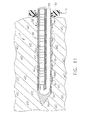
- FIG. 11 is a left side view in elevation taken in longitudinal cross section through a probe for the disposable probe assembly of FIG. 1 inserted into tissue.
- FIG. 12 is an isometric exploded view of the reusable hand piece of FIG. 1 .
- FIG. 13 is a bottom view of the assembled biopsy device of FIG. 1 taken in horizontal cross section through the probe.
- FIG. 14 is an isometric view of the probe having dimpled external vacuum holes formed on the disposable probe assembly of FIG. 1 with a piercing tip omitted and a cutter tube detached.
- FIG. 15 is an isometric view of an alternate probe having a plurality of longitudinal rows of external vacuum holes for the disposable probe assembly of FIG. 1 with a piercing tip omitted and a cutter tube detached also having a plurality of longitudinal rows of holes.
- FIG. 16 is an isometric view of another alternate probe having a longitudinally spaced plurality of transverse external vacuum slots for the disposable probe assembly of FIG. 1 with a piercing tip omitted and a cutter tube detached also having a plurality of longitudinally spaced plurality of transverse holes.
- FIG. 17 is an isometric view of an additional alternate probe having a plurality of longitudinal external vacuum slots aligned into radially spaced longitudinal rows for the disposable probe assembly of FIG. 1 with a piercing tip omitted and a cutter tube detached also having a plurality of longitudinal slots.
- FIG. 18 is an isometric view of a further alternate probe having a plurality of parallel, spiraled external vacuum slots for the disposable probe assembly of FIG. 1 with a piercing tip omitted and a cutter tube detached also having a plurality of spiraled slots.
- FIG. 19 is an isometric view of yet another additional alternate probe having a plurality of longitudinal rows of reduced diameter external vacuum holes for the disposable probe assembly of FIG. 1 with a piercing tip omitted and a cutter tube detached also having a plurality of longitudinal rows of reduced diameter holes.
- FIG. 20 is an isometric view of yet a further alternative probe having a plurality of longitudinal rows of external vacuum holes with diameters graduated with relation to longitudinal distance along the shaft for the disposable probe assembly of FIG. 1 with a piercing tip omitted.
- FIG. 21 is a left side view of the probe of FIG. 15 in longitudinal vertical cross section and inserted into tissue with cutter tube advanced to close a side aperture and with a sample retraction straw with internal indicator tube retracted exposing internal vacuum holes partially aligned with external vacuum holes.
- FIG. 22 is a left side view of the probe of FIG. 20 in longitudinal vertical cross section with the cutter tube retracted and vacuum assistance prolapsing tissue into the side aperture and removing bleeding around the probe.
- FIG. 23 is a left side view of the probe of FIG. 22 in longitudinal vertical cross section with the cutter tube advanced to sever a tissue sample.
- FIG. 24 is a left side view of the probe of FIG. 23 in longitudinal vertical cross section with the cutter tube advanced a second time severing a second tissue sample with a sample retraction straw advanced within the cutter tube to capture both tissue samples, the latter urging the indicator tube aft.
- FIG. 25 is an isometric short aperture sleeve with adjustable hemostatic ring for the biopsy device of FIG. 1 .
- FIG. 26 is a left side view of the probe of FIG. 6 in longitudinal cross section with the cutter tube advanced to sever a second tissue sample close to the skin with a side aperture sleeve with adjustable hemostatic ring to avoid skin gouging by the cutter tube.
- a biopsy device 10 has a reusable hand piece 11 and a disposable probe assembly 12 that enables economical taking of multiple percutaneous core biopsy samples through a core biopsy needle (probe) 13 that is inserted into tissue.
- a vacuum source 14 e.g., standard medical vacuum pump or wall-mounted vacuum access port.
- bleeding and fluid management is enhanced by drawing fluid through external vacuum holes 15 formed distally in the probe 13 of the disposable probe assembly 12 through a first interfacing vacuum conduit 16 a which connects the vacuum source 14 to a first port 17 a of a vacuum canister 18 for catching extracted fluids and a second interfacing vacuum conduit 16 b which connects a second port 17 b of the vacuum canister 18 to the disposable probe assembly 12 .
- bleeding and fluid management is further enhanced by proximally positioning a disk-shaped hemostatic ring pad 19 over the probe 13 positioned away from a housing 20 of the reusable hand piece 11 to abut an external opening formed through the skin (not shown).
- a front absorbent surface 19 a of the hemostatic ring pad 19 absorbs fluid and resiliently contacts the skin.
- An opaque and impermeable back surface (e.g., dark thermoplastic) 19 b of the hemostatic ring pad 19 supports the front absorbent surface 19 a , obscures patient view of absorbed blood, and completes a pneumatic seal over the opening.
- the hemostatic ring pad 19 may frictionally engage the probe 13 .
- a through hole may be formed by inserting the probe 13 through the hemostatic ring pad 19 .
- the sterility of the absorbent material may be maintained by packing that is adhesively attached to a front outer ring of the back surface 19 b .
- the remaining adhesive may facilitate placement of the hemostatic ring pad at a desired insertion point on the skin a scored central portion of the hemostatic ring pad 19 helps locate the insertion point of the probe 13 .
- the illustrative version is disk-shaped, it a hemostatic pad consistent with aspects of the present invention may have various geometric shapes.
- the absorbent material may be omitted relying upon compression asserted by the back surface.
- the backing may be omitted relying solely upon absorption or the inherent stiffness of the absorbent material.
- it may be desired not to use an opaque backing material but rather a translucent or transparent material so as to view the amount of external bleeding.
- locking features may be incorporated between a hemostatic ring pad and a probe to locking the hemostatic ring pad at a proximal position indicating full insertion.
- the hand piece 11 is self-powered and suitable for use in conjunction with ultrasonic diagnostic imaging.
- the disposable probe assembly 12 reduces the portion of biopsy device 10 that requires protective packaging to avoid contact with sharp surfaces and to keep it sterile prior to use. Further economy is accomplished by reducing the portion of the biopsy device 10 that is disposed as medical waste between uses. Movable components of the disposable probe assembly 12 are advantageously locked until mounted in an access trough 21 ( FIG. 1 ) formed in the housing 20 of the reusable hand piece 11 . It should be appreciated that one or more standard mechanical, pneumatic, or electrical latches (not shown) may be integrated into the biopsy device 10 to secure the disposable probe assembly 12 to the reusable hand piece 11 .
- the disposable probe assembly 12 includes a substantially rectangular cover 22 sized to close the access trough recess 21 ( FIG. 1 ).
- An end slot 24 formed in the housing 20 is closed by a probe union sleeve 26 attached to an inner surface 27 of the substantially rectangular cover 22 .
- the core biopsy needle (“probe”) assembly 13 passes longitudinally through the probe union sleeve 26 and is formed by a probe tube 30 with underlying vacuum lumen 32 that communicates with a side aperture 34 through inter lumen holes 35 ( FIG. 11 ) near a distal opening 36 of the probe tube 30 that is closed by a piercing tip 38 .
- a cutter tube 40 is sized to closely fit and translate within an inner diameter (i.e., cutter lumen) of the probe tube 30 .
- Cutter holes 39 near a distal end 41 of the cutter tube 40 may be included allow bleeding and fluid management through the cutter tube 40 .
- the cutter tube 40 has a longitudinal length sufficient to close the side aperture 34 with a proximal end 42 extending from the probe union sleeve 26 to attach to a cutter gear 44 , as depicted in FIGS. 2 , 10 .
- This non-cylindrical probe 13 includes one passage that passes through the cutter tube 40 that is encompassed closely by the probe tube 30 and includes a “hard-walled” vacuum (lateral) lumen 32 that is under slung and attached to the probe tube 30 , communicating with the other passage proximate to the side aperture 34 .
- an alternate cylindrical probe 13 ′ for the disposable probe assembly 12 of FIG. 1 advantageously incorporates a piercing tip 38 ′ attached at a proximal circular external recess 37 ′ ( FIG. 7 ) for free rotation about its longitudinal axis to a distal opening in a probe tube 30 ′.
- desired non-conical cutting surfaces may be incorporated that reduce the insertion forces that do not impede rotation of the probe tube 30 ′.
- the cylindrical distal end of the probe tube 30 ′ ends in an outer race 46 ′ proximal to a recessed lip 47 ′.
- the piercing tip 38 ′ is formed by a cylindrical base 48 ′ attached to a split cone tip 49 ′ that receives a triangular blade 51 ′ held by beveled pin 59 ′.
- a cylindrical collar 53 ′ grips the cylindrical base 48 ′ and has proximal inward lip 55 ′ that resides within the outer race 46 ′ of the probe tube 30 ′.
- a bearing 57 ′ between the recessed lip 47 ′ of the probe tube 30 ′ and the cylindrical base 48 ′ of the piercing tip 38 ′ enhances low friction rotation.
- a cutting surface such as the triangular blade 51 ′ may be selected for reduced insertion force, etc., yet not impede rotation of the side aperture 34 ′ of the probe tube 30 ′.
- an axially off-center cutter tube 40 ′ within the probe tube 30 ′ acts as a “soft-wall”, defining first and second fluid passages that are separated longitudinally within the probe tube 30 ′ that distally communicate with each other at a side aperture 34 ′ formed in the probe tube 30 ′.
- a first fluid passage is defined within the cutter tube 40 ′ and the second fluid passage is defined within the probe tube 30 ′ but outside of cutter tube 40 ′. Fluid communication between the fluid passages is enhanced by a concave proximal end 43 ′ of piercing tip 38 ′ and cutter holes 39 ′.
- Bleeding and fluid management is also enhanced by a central fluid cavity 61 ′ that communicates between the distal opening 36 ′ of the probe tube 30 ′ and small fluid passages 45 ′ formed in the split cone tip 49 ′ of the piercing tip 38 ′ that transition from the concave proximal end 43 ′ to an exterior of the piercing tip 38 ′.
- proximal to the probe union sleeve 26 is an elongate slot 50 that is part of a vacuum assist valve assembly 52 .
- the cutter gear 44 includes distal and proximal annular recesses 54 , 56 flanking spur gear teeth 58 that engage the reusable hand piece 11 as described below.
- a more distal annular recess 60 is gripped by a post 62 that is engaged to longitudinally translate in an elongate post slot 64 of a distal portion 66 of a vacuum valve actuator 68 .
- a cylindrical proximal portion 70 of the vacuum valve actuator 68 has distal and proximal O-ring grooves 72 , 73 that respectively retain distal and proximal dynamic O-ring seals 74 , 75 that move within a distally open cylindrical valve bore 76 of a valve body 78 molded onto an outer surface 79 of the substantially rectangular cover 22 ( FIG. 1 ).
- the vacuum valve actuator 68 selectively allows communication between a proximal port 80 , a center port 82 , and a distal port 84 ( FIG. 2 ).
- a proximal port 80 With the cutter gear 44 retracted, the proximal and center ports 80 , 82 are in communication. With the cutter gear translated distally, the center and distal ports 82 , 84 communicate.
- the center port 82 is attached to a distal vacuum conduit 86 whose other end is connected through the rectangular cover 22 to the probe union sleeve 26 .
- the probe union sleeve 26 includes pneumatic passages that communicate between a proximal end of the vacuum lumen 32 and the distal vacuum conduit 86 .
- the distal port 84 is attached to a hose nib 88 that is exposed to atmospheric pressure.
- Hose nib 88 may include an air and/or saline filter.
- hose nib 88 may be connected to a positive pressure source (e.g., fluid pump) or a negative pressure source (e.g., vacuum pump, syringe) to aspirate fluids.
- hose nib 88 may be used to lavage the tissue cavity with saline, pain medication, or bleeding control fluids.
- the proximal port 80 communicates through a proximal vacuum conduit 90 to the interfacing vacuum conduit 16 a.
- a sample extraction feature is incorporated so that multiple samples may be made without the need to remove the probe 13 from tissue nor even to full retract the cutter tube 40 to retract a tissue specimen to the reusable hand piece 11 .
- this feature is accomplished with a stacking straw assembly 100 .
- An elongate straw 102 is scored down its length on opposite sides by grooves 104 defining first and second straw halves 106 , 108 , whose respective proximal, outer surfaces 110 , 112 are attached to triangular grips 114 , 116 , respectively.
- a locking strip 118 extends distally from one triangular grip 114 and is attached along a proximal portion of the first straw half 106 .
- Distal and proximal tabs 120 , 122 extend from the inner surface 27 of the substantially rectangular cover 22 , each having a respective through hole 124 , 126 through which the stacking straw assembly 100 is inserted.
- the through holes 124 , 126 are shaped to allow the locking strip 118 to rotate ninety (90) degrees.
- a bayonet locking member 130 also extends from the inner surface 27 of the substantially rectangular cover 22 just distal and laterally offset from the through hole 124 of the distal tab 120 to lock into an alignment locking slot 132 in the locking strip 118 when laterally rotated. The bayonet locking member 130 prevents axial movement of the stacking straw assembly 100 .
- an indicator tube 150 has a stacked cone-shaped outer surface 152 ( FIG. 11 ) that slides within the elongate straw 104 that in turn slides within the cutter tube 40 .
- proximal stacker An alternative sample retrieval approach (“proximal stacker”) is also described in the aforementioned patent application Ser. No. 11/198,558 that uses vacuum without a stacking straw 104 (not shown).
- proximal stacker a similar sample holding portion that does not use a stacking straw 104 for retrieval is described in five commonly-owned and co-pending U.S. patent application Ser. No. 10/953,834, “Biopsy Apparatus and Method”, END-5469; Ser. No. 10/953,904, “Improved Biopsy Apparatus and Method”, END 5470; Ser. No. 10/953,397, “Fluid Control for Biopsy Device”, END 5471; Ser. No.
- the probe 13 defines first and second fluid passages that are separated longitudinally within the probe 13 and distally communicate with each other at the side aperture 34 .
- the first fluid passage is defined within the cutter tube 40 and the second fluid passage is defined within the lateral lumen 32 that is “hard walled” apart from a cylindrical portion of the cutter lumen of the probe tube 35 .
- a cutter tube may be axially offset within the cutter lumen of the probe tube such that the cutter tube may separate the first and second fluid passages, especially if the cutter tube need not be retracted for retraction of samples (e.g., vacuum retraction, straw retraction, single sample per insertion devices).
- samples e.g., vacuum retraction, straw retraction, single sample per insertion devices.
- the reusable hand piece 11 includes four user controls aligned on a top surface 160 of the housing 20 , specifically from most distal to most proximal: a forward motor rotation key 162 , a reverse motor rotation key 164 , a saline flush key 166 and a slide button 168 for selecting insertion mode or sample taking mode.
- the keys 162 - 166 control a control circuit 170 , which may include integral power storage (e.g., batteries, fuel cell, etc.) for untethered use.
- integral power storage e.g., batteries, fuel cell, etc.
- the forward motor rotation key 162 causes a DC motor 172 to rotate its motor output shaft 174 in a forward rotation.
- a slide spur gear 176 includes an internal keyed engagement with a longitudinal key groove 178 on the motor output shaft 174 that allows longitudinal positioning by the slide button 168 .
- fore and aft brackets 180 , 182 of the slide button 168 engage distal and aft annular grooves 184 , 186 that flank spur gear teeth 188 of the slide spur gear 176 .
- the slide spur gear 176 engages a tissue penetration gear 190 that spins on a common shaft centerline 192 forward of a gearbox input gear 196 .
- Gearbox input gear 196 consists of a distal small gear 198 and a proximal large gear 200 .
- the tissue penetration gear 190 has spur gear teeth 206 that engage the slide spur gear 176 .
- a frame post 212 projects proximally from an aft wall 213 of a frame 204 with a strike pin 214 projecting upwardly from the frame post 212 .
- a circular cam wheel 216 is attached to a distal side of the tissue penetration gear 190 .
- Rotating the tissue penetration gear 190 urges the strike pin 214 , and thus the frame 204 , proximally.
- Left and right spring cavities 218 , 220 (when viewed from above), formed longitudinally in distal corners of the frame 204 , respectively receive inwardly projecting left and right tabs 222 , 224 ( FIG. 1 ) from the housing 20 and receive left and right compression springs 226 , 228 .
- a distal end of each compression spring 226 , 228 presses against a distal inner surface of the respective spring cavity 218 , 220 .
- a proximal end of each compression spring 226 , 288 is grounded against a respective tab of the housing 20 .
- the frame 204 is biased distally within the housing 20 . Movement of the frame 204 proximally compresses these compression springs 226 , 228 that thereafter assert a restoring force.
- the slide spear gear 176 When the slide button 168 is moved proximally, the slide spear gear 176 is moved into engagement with the gearbox input gear 196 , specifically the distal small gear 198 , which engages and turns a translation large input gear 230 whose shaft 232 passes through the aft wall 213 of the frame 204 .
- the proximal large gear 200 of the gearbox input gear 196 engages and turns a rotation small input gear 236 whose shaft 238 passes through the aft wall 213 .
- the frame 204 includes a carriage recess 240 , defined between a partition 242 and the aft wall 213 .
- the carriage recess 240 contains longitudinally aligned left side lead (translation) screw 244 and right-side rotation spur gear 246 that are attached for rotation respectively with the shafts 232 , 238 .
- the partition 242 is positioned aft of the left and right tabs 222 , 224 of the housing 20 and also defines in part the left and right spring cavities 218 , 220 .
- An unlocking cam 247 projects proximally from and is longitudinally centered on the aft wall 234 above the position of the lead (translation) screw 244 and rotation spur gear 246 .
- the rotation spur gear 246 engages the cutter gear 44 when the disposable probe assembly 12 is inserted, imparting a rotation as the cutter tube 40 and cutter gear 44 translate longitudinally in response to the rotation of the lead (translation) screw 244 .
- This translation is caused by lead screw threads 248 .
- a distal carriage (cutter carriage) 250 is longitudinally moved on the lead screw threads 248 .
- Distal and proximal J-hook extensions 252 , 254 project downwardly from the distal carriage 250 to engage the distal and proximal annular recesses 54 , 56 of the cutter gear 44 .
- a biasing spring 256 urges against the distal carriage 250 , which assists in engagement of the lead screw threads 248 with the distal carriage 250 .
- a sliding pin 260 has a proximal carriage sliding pin retainer 266 attached to a proximal carriage 258 .
- a shaft 264 of the sliding pin 260 also passes through a distal carriage sliding pin retainer 270 attached to the distal carriage 250 .
- Sliding pin 260 has a proximal end 262 and a distal end 268 to prevent the sliding pin 260 from disengaging from the carriage sliding pin retainers 266 , 270 .
- a sliding pin spring 272 resides on the sliding pin 260 and is constrained at each end by carriage sliding pin retainers 266 , 270 .
- the interfacing vacuum lumen 16 a is attached to the disposable probe assembly 12 ( FIGS. 1-2 ).
- the disposable probe assembly 12 is installed into the reusable hand piece 11 ( FIGS. 3 , 13 ).
- the distal cutter carriage 250 engages the cutter gear 44
- the proximal straw carriage 258 engages the locking strip 118 of the stacking straw assembly 100
- the bayonet locking member 130 is deflected by the unlocking cam 247 , longitudinally unlocking from the alignment locking slot 132 of the locking strip 118 allowing longitudinal movement of the cutter tube 40 and the straw stacking assembly 100 .
- the reusable handpiece 11 is manipulated to insert the piercing tip 38 of the core biopsy needle (probe) assembly 13 into tissue. Penetration of dense tissue is assisted by moving the slide button 168 distally to a “tissue insertion mode” wherein the slide spur gear 176 engages the tissue penetration gear 190 . Depression of the forward motor rotation key 162 turns these gears 176 , 190 causing the circular cam wheel 216 to turn against strike pin 214 that creates proximal longitudinal motion of frame 204 and the attached core biopsy needle (probe) assembly 13 of approximately 0.1 inch at a rotation rate of 7 cycles per second.
- Left and right compression springs 226 , 228 provide the restoring distal longitudinal motion to frame 204 and probe assembly 28 as left and right compression springs 226 , 228 are repeatedly compressed between the distal surface of the left and right spring cavities 218 , 220 of the frame 204 and the left and right tabs 222 , 224 of the housing 20 .
- the restoring distal longitudinal motion to frame 204 and core biopsy needle (probe) assembly 28 result in a corresponding distal motion of piecing tip 38 that assists in penetrating tissue.
- Bleeding and fluid management is enhanced by vacuum being drawn through the external vacuum holes 15 into the vacuum lumen 32 .
- the external vacuum holes 15 reside within a protruding dimple structure 300 formed in the lateral lumen 32 which mitigates a tendency of adjacent tissue to be drawn into and plug an external vacuum hole 15 .
- the cutter holes 39 formed in a distal end 41 of the cutter tube 40 assist in drawing fluid when the cutter tube 40 is advanced, otherwise closing the side aperture 34 .
- an alternate probe 13 a has a plurality of longitudinal rows of external vacuum holes 15 a .
- a cutter tube 40 a has a plurality of longitudinal rows of cutter holes 39 a for assisting in bleeding and fluid management.
- the exterior of a probe tube 30 a has some of the vacuum holes 15 a , in addition to those in a vacuum lumen 32 a , such that cutter holes 39 a in the cutter tube 40 a may readily communicate externally.
- another alternate probe 13 b has a longitudinally spaced plurality of transverse external vacuum slots 15 b formed in a vacuum lumen 32 b but not a probe tube 30 b .
- a cutter tube 40 b also has a plurality of longitudinally spaced plurality of transverse cutter slots 39 b.
- an additional alternate probe 13 c has a plurality of longitudinal external vacuum slots 15 c formed in both a vacuum lumen 32 c and a probe tube 30 c .
- a cutter tube 40 c also has a plurality of longitudinal cutter slots 39 c.
- a further alternate probe 13 d has a plurality of parallel, spiraled external vacuum slots 15 d formed in a vacuum lumen 32 d but not a probe tube 30 d .
- a cutter tube 40 d also has a plurality of spiraled cutter slots 39 d.
- yet another additional alternate probe 13 e has a plurality of longitudinal rows of reduced diameter external vacuum holes 15 e .
- a cutter tube 40 e has a plurality of longitudinal rows of reduced diameter cutter holes 39 e for assisting in bleeding and fluid management.
- the exterior of a probe tube 30 e has some of the vacuum holes 15 e in addition to those in a vacuum lumen 32 e such that reduced diameter cutter holes 39 e in the cutter tube 40 e may readily communicate externally.
- yet a further alternative probe 13 f has a plurality of longitudinal rows of graduated diameter external vacuum holes 15 f - 15 h in a probe tube 30 f , with the largest external vacuum holes 15 h most distal, the smallest external vacuum holes 15 f most proximal, and the mid-sized external vacuum holes 15 g in between.
- the cross sectional area of the holes 15 f - h are selected to correspond with a typical vacuum pressure drop as a function of longitudinal position on the probe tube 30 f , thereby tending to avoid the likelihood of higher vacuum proximally tending to suck in tissue.
- the probe 13 a is inserted into body tissue 304 with a hole formed by the piercing tip 38 .
- the cutter tube 40 a is distally advanced to close the side aperture 34 in the probe tube 30 a to reduce tissue trauma during insertion.
- the stacking straw assembly 100 is retracted to an initial position. Vacuum assistance is present through both the cutter tube 40 a and the vacuum lumen 32 b during insertion, encouraging bodily fluids (e.g., blood) 306 to be drawn into external vacuum holes 15 a and additionally into cutter holes 39 a being drawn aft for collection, and with a sample retraction straw with internal indicator tube retracted exposing internal vacuum holes partially aligned with external vacuum holes. Bleeding closer to an external opening in skin tissue 308 that is not drawn into the probe 13 a is captured into the front absorbent material 19 a of the hemostatic disk-shaped ring pad 19 that encompasses and frictionally grips the probe 13 a.
- the cutter tube 40 a is retracted, allowing vacuum assistance from both the cutter tube 40 a and vacuum lumen 32 a to prolapse tissue 304 into the side aperture 34 of the probe tube 30 a .
- distal advancement of the cutter tube 40 a has resulted in severing of a first tissue sample 304 a encompassed therein.
- the elongate straw 102 has been distally advanced within the cutter tube 40 a , which in the interim has been reciprocated another time, to encompass and capture the first tissue sample 304 a as well as a second tissue sample 304 b which has been severed in the interim by another reciprocation of the cutter tube 40 a .
- the presence of the tissue samples 304 a , 304 b in the elongate straw 102 extrudes aft the indicator straw 150 .
- a sleeve 400 advantageously assists in bleeding control as well as enabling the taking of biopsy samples of a lesion 402 close to the surface wherein the side aperture 34 is partially exposed.
- a taper distal end 404 of a cylindrical tube 406 of the sleeve 400 may be longitudinally positioned by gripping a pushing a proximal disk flange 408 .
- the sleeve 400 has been slid overtop of the exposed portion of the side aperture 34 ′ of the probe 13 f so that the cutter 40 a doesn't gouge skin as it translates from outside of the body across the side aperture 34 ′.
- the sleeve 400 may further plug the external opening in the skin to further reduce external bleeding, not only with its increased diameter of the cylindrical tube 406 but also by positioning a hemostatic ring 410 .
- an absorbent ring 412 frictionally engages the cylindrical tube 406 .
- a rigid backplane 414 attached proximally to the absorbent ring 412 may be included for moving the hemostatic ring 412 into contact with the skin.
- bleeding and fluid management may be enhanced by flushing the external vacuum holes 15 to remove tissue debris and coagulated blood, such as described in the co-pending and commonly-owned U.S. patent application Ser. No. 11/344,879, “Biopsy Device with Replaceable Probe Incorporating Static Vacuum Source Dual Valve Sampling Stacking Retrieval and Saline Flush” to Hibner, filed 1 Feb. 2006, the disclosure of which is hereby incorporated by reference in its entirety.
- a sleeve with a piercing tip or a sleeve with an open distal end closed by an introducer stylet are used to penetrate tissue prior to insertion of a probe of a biopsy device for taking the biopsy samples.
- pneumatic fluid passages may be formed in the sleeve and/or introducer stylet that communicate proximally with a vacuum source for bleeding and fluid management.
- a hemostatic disc-shaped ring pad may be added to the sleeve to further assist in preventing or obscuring external bleeding.
- applications consistent with the present invention may not rotate the cutter tube or selectively rotate the cutter tube to present sampling holes to the side aperture or to a hole in an encompassing probe tube to assist in bleeding/fluid management. Rotating these holes to be blocked during other portions of the procedure may then enhance the available suction for retraction of a tissue sample, for instance.
Abstract
Description
Claims (20)
Priority Applications (1)
| Application Number | Priority Date | Filing Date | Title |
|---|---|---|---|
| US13/760,364 US8979769B2 (en) | 2005-08-05 | 2013-02-06 | Biopsy device with vacuum assisted bleeding control |
Applications Claiming Priority (4)
| Application Number | Priority Date | Filing Date | Title |
|---|---|---|---|
| US11/198,558 US7867173B2 (en) | 2005-08-05 | 2005-08-05 | Biopsy device with replaceable probe and incorporating vibration insertion assist and static vacuum source sample stacking retrieval |
| US11/424,576 US7918804B2 (en) | 2005-08-05 | 2006-06-16 | Biopsy device with vacuum assisted bleeding control |
| US13/025,366 US8568335B2 (en) | 2005-08-05 | 2011-02-11 | Biopsy device with vacuum assisted bleeding control |
| US13/760,364 US8979769B2 (en) | 2005-08-05 | 2013-02-06 | Biopsy device with vacuum assisted bleeding control |
Related Parent Applications (1)
| Application Number | Title | Priority Date | Filing Date |
|---|---|---|---|
| US13/025,366 Continuation US8568335B2 (en) | 2005-08-05 | 2011-02-11 | Biopsy device with vacuum assisted bleeding control |
Publications (2)
| Publication Number | Publication Date |
|---|---|
| US20130150750A1 US20130150750A1 (en) | 2013-06-13 |
| US8979769B2 true US8979769B2 (en) | 2015-03-17 |
Family
ID=37718487
Family Applications (10)
| Application Number | Title | Priority Date | Filing Date |
|---|---|---|---|
| US11/198,558 Expired - Fee Related US7867173B2 (en) | 2005-08-05 | 2005-08-05 | Biopsy device with replaceable probe and incorporating vibration insertion assist and static vacuum source sample stacking retrieval |
| US11/424,576 Active 2029-02-07 US7918804B2 (en) | 2005-08-05 | 2006-06-16 | Biopsy device with vacuum assisted bleeding control |
| US12/959,506 Active US8235913B2 (en) | 2005-08-05 | 2010-12-03 | Biopsy device with translating valve member |
| US13/025,366 Expired - Fee Related US8568335B2 (en) | 2005-08-05 | 2011-02-11 | Biopsy device with vacuum assisted bleeding control |
| US13/490,613 Active 2026-05-03 US8911381B2 (en) | 2005-08-05 | 2012-06-07 | Biopsy device with translating valve member |
| US13/760,364 Expired - Fee Related US8979769B2 (en) | 2005-08-05 | 2013-02-06 | Biopsy device with vacuum assisted bleeding control |
| US14/040,798 Expired - Fee Related US9005136B2 (en) | 2005-08-05 | 2013-09-30 | Biopsy device with vacuum assisted bleeding control |
| US14/543,050 Expired - Fee Related US9901327B2 (en) | 2005-08-05 | 2014-11-17 | Biopsy device with translating valve member |
| US15/198,403 Active US9907542B2 (en) | 2005-08-05 | 2016-06-30 | Biopsy device with translating valve member |
| US15/865,358 Active 2026-11-17 US11224412B2 (en) | 2005-08-05 | 2018-01-09 | Biopsy device with translating valve member |
Family Applications Before (5)
| Application Number | Title | Priority Date | Filing Date |
|---|---|---|---|
| US11/198,558 Expired - Fee Related US7867173B2 (en) | 2005-08-05 | 2005-08-05 | Biopsy device with replaceable probe and incorporating vibration insertion assist and static vacuum source sample stacking retrieval |
| US11/424,576 Active 2029-02-07 US7918804B2 (en) | 2005-08-05 | 2006-06-16 | Biopsy device with vacuum assisted bleeding control |
| US12/959,506 Active US8235913B2 (en) | 2005-08-05 | 2010-12-03 | Biopsy device with translating valve member |
| US13/025,366 Expired - Fee Related US8568335B2 (en) | 2005-08-05 | 2011-02-11 | Biopsy device with vacuum assisted bleeding control |
| US13/490,613 Active 2026-05-03 US8911381B2 (en) | 2005-08-05 | 2012-06-07 | Biopsy device with translating valve member |
Family Applications After (4)
| Application Number | Title | Priority Date | Filing Date |
|---|---|---|---|
| US14/040,798 Expired - Fee Related US9005136B2 (en) | 2005-08-05 | 2013-09-30 | Biopsy device with vacuum assisted bleeding control |
| US14/543,050 Expired - Fee Related US9901327B2 (en) | 2005-08-05 | 2014-11-17 | Biopsy device with translating valve member |
| US15/198,403 Active US9907542B2 (en) | 2005-08-05 | 2016-06-30 | Biopsy device with translating valve member |
| US15/865,358 Active 2026-11-17 US11224412B2 (en) | 2005-08-05 | 2018-01-09 | Biopsy device with translating valve member |
Country Status (9)
| Country | Link |
|---|---|
| US (10) | US7867173B2 (en) |
| EP (3) | EP1921997A4 (en) |
| JP (2) | JP2009502434A (en) |
| CN (1) | CN101237822B (en) |
| AU (1) | AU2006278678B2 (en) |
| CA (1) | CA2617904C (en) |
| HK (1) | HK1255710A1 (en) |
| PL (1) | PL2455000T3 (en) |
| WO (1) | WO2007019152A2 (en) |
Cited By (1)
| Publication number | Priority date | Publication date | Assignee | Title |
|---|---|---|---|---|
| US9968339B2 (en) | 2005-08-05 | 2018-05-15 | Devicor Medical Products, Inc. | Biopsy device with rotatable tissue sample holder |
Families Citing this family (197)
| Publication number | Priority date | Publication date | Assignee | Title |
|---|---|---|---|---|
| US6758824B1 (en) * | 2000-11-06 | 2004-07-06 | Suros Surgical Systems, Inc. | Biopsy apparatus |
| EP1487346B1 (en) | 2002-03-19 | 2005-08-31 | Bard Dublin ITC Limited | Vacuum biopsy device |
| MXPA04008781A (en) | 2002-03-19 | 2005-12-15 | Bard Dublin Itc Ltd | Biopsy device and biopsy needle module that can be inserted into the biopsy device. |
| CA2494377C (en) * | 2002-08-01 | 2012-09-25 | James E. Selis | Biopsy devices and methods |
| US7794408B2 (en) | 2003-03-28 | 2010-09-14 | Ethicon, Inc. | Tissue collection device and methods |
| DE20305093U1 (en) | 2003-03-29 | 2003-09-11 | Heske Norbert F | Coaxial cannula with sealing element |
| DE10314240A1 (en) * | 2003-03-29 | 2004-10-07 | Bard Dublin Itc Ltd., Crawley | Pressure generating unit |
| US20120289859A9 (en) * | 2003-08-27 | 2012-11-15 | Nicoson Zachary R | System and method for minimally invasive disease therapy |
| US8034003B2 (en) | 2003-09-11 | 2011-10-11 | Depuy Mitek, Inc. | Tissue extraction and collection device |
| US7611473B2 (en) | 2003-09-11 | 2009-11-03 | Ethicon, Inc. | Tissue extraction and maceration device |
| US8075568B2 (en) | 2004-06-11 | 2011-12-13 | Selis James E | Biopsy devices and methods |
| ES2398914T3 (en) | 2004-07-09 | 2013-03-22 | Bard Peripheral Vascular, Inc. | Transport system for biopsy device |
| US20060074345A1 (en) * | 2004-09-29 | 2006-04-06 | Hibner John A | Biopsy apparatus and method |
| US7517321B2 (en) | 2005-01-31 | 2009-04-14 | C. R. Bard, Inc. | Quick cycle biopsy system |
| US20060286004A1 (en) * | 2005-06-15 | 2006-12-21 | Jacobs Merrit N | Containers for reducing or eliminating foaming |
| US7662109B2 (en) * | 2006-02-01 | 2010-02-16 | Ethicon Endo-Surgery, Inc. | Biopsy device with replaceable probe incorporating static vacuum source dual valve sample stacking retrieval and saline flush |
| USRE46135E1 (en) | 2005-08-05 | 2016-09-06 | Devicor Medical Products, Inc. | Vacuum syringe assisted biopsy device |
| US7828748B2 (en) * | 2005-08-05 | 2010-11-09 | Devicor Medical Products, Inc. | Vacuum syringe assisted biopsy device |
| US20080004545A1 (en) * | 2005-08-05 | 2008-01-03 | Garrison William A | Trigger Fired Radial Plate Specimen Retrieval Biopsy Instrument |
| US7896817B2 (en) | 2005-08-05 | 2011-03-01 | Devicor Medical Products, Inc. | Biopsy device with manually rotated sample barrel |
| US7867173B2 (en) | 2005-08-05 | 2011-01-11 | Devicor Medical Products, Inc. | Biopsy device with replaceable probe and incorporating vibration insertion assist and static vacuum source sample stacking retrieval |
| EP1924205B1 (en) | 2005-08-10 | 2012-12-19 | C.R.Bard, Inc. | Single-insertion, multiple sample biopsy device |
| EP2196155B1 (en) | 2005-08-10 | 2015-03-18 | C.R.Bard, Inc. | Single-insertion, multiple sample biopsy device with various transport system |
| EP1921998B8 (en) | 2005-08-10 | 2021-07-07 | C.R.Bard, Inc. | Single-insertion, multiple sampling biopsy device with linear drive |
| EP2061378B1 (en) | 2006-08-21 | 2018-10-03 | C.R.Bard, Inc. | Self-contained handheld biopsy needle |
| DE602007004546D1 (en) | 2006-09-28 | 2010-03-18 | Tyco Healthcare | Portable wound therapy system |
| WO2008040812A1 (en) | 2006-10-06 | 2008-04-10 | Sonion Roskilde A/S | Tissue handling system with reduced operator exposure |
| EP2086417B1 (en) | 2006-10-24 | 2015-07-01 | C.R.Bard, Inc. | Large sample low aspect ratio biopsy needle |
| US9345457B2 (en) | 2006-12-13 | 2016-05-24 | Devicor Medical Products, Inc. | Presentation of biopsy sample by biopsy device |
| US7938786B2 (en) * | 2006-12-13 | 2011-05-10 | Devicor Medical Products, Inc. | Vacuum timing algorithm for biopsy device |
| US20140039343A1 (en) | 2006-12-13 | 2014-02-06 | Devicor Medical Products, Inc. | Biopsy system |
| US8480595B2 (en) * | 2006-12-13 | 2013-07-09 | Devicor Medical Products, Inc. | Biopsy device with motorized needle cocking |
| US8251916B2 (en) | 2006-12-13 | 2012-08-28 | Devicor Medical Products, Inc. | Revolving tissue sample holder for biopsy device |
| US8702623B2 (en) | 2008-12-18 | 2014-04-22 | Devicor Medical Products, Inc. | Biopsy device with discrete tissue chambers |
| DE602007006137D1 (en) | 2006-12-13 | 2010-06-10 | Ethicon Endo Surgery Inc | Biopsy Sample Storage |
| US20120283563A1 (en) | 2011-05-03 | 2012-11-08 | Moore Kyle P | Biopsy device with manifold alignment feature and tissue sensor |
| US7981049B2 (en) * | 2006-12-13 | 2011-07-19 | Devicor Medical Products, Inc. | Engagement interface for biopsy system vacuum module |
| US20130324882A1 (en) | 2012-05-30 | 2013-12-05 | Devicor Medical Products, Inc. | Control for biopsy device |
| US20080221605A1 (en) * | 2007-01-26 | 2008-09-11 | Laurimed Llc | Cutting device positioned via control wire to perform selective discectomy |
| US8088119B2 (en) * | 2007-02-01 | 2012-01-03 | Laurimed, Llc | Methods and devices for treating tissue |
| GB0712763D0 (en) | 2007-07-02 | 2007-08-08 | Smith & Nephew | Apparatus |
| US20090036963A1 (en) * | 2007-08-01 | 2009-02-05 | Kirsch Daniel L | Probe electrode pad and probe electrode pad storage box |
| US7806835B2 (en) * | 2007-11-20 | 2010-10-05 | Devicor Medical Products, Inc. | Biopsy device with sharps reduction feature |
| US7858038B2 (en) * | 2007-11-20 | 2010-12-28 | Devicor Medical Products, Inc. | Biopsy device with illuminated tissue holder |
| US20090131819A1 (en) | 2007-11-20 | 2009-05-21 | Ritchie Paul G | User Interface On Biopsy Device |
| US8454531B2 (en) | 2007-11-20 | 2013-06-04 | Devicor Medical Products, Inc. | Icon-based user interface on biopsy system control module |
| US8052616B2 (en) * | 2007-11-20 | 2011-11-08 | Devicor Medical Products, Inc. | Biopsy device with fine pitch drive train |
| US9039634B2 (en) * | 2007-11-20 | 2015-05-26 | Devicor Medical Products, Inc. | Biopsy device tissue sample holder rotation control |
| US7575556B2 (en) | 2007-11-20 | 2009-08-18 | Ethicon Endo-Surgery, Inc. | Deployment device interface for biopsy device |
| US20090131821A1 (en) * | 2007-11-20 | 2009-05-21 | Speeg Trevor W V | Graphical User Interface For Biopsy System Control Module |
| WO2009066106A1 (en) | 2007-11-21 | 2009-05-28 | Smith & Nephew Plc | Wound dressing |
| US8241225B2 (en) | 2007-12-20 | 2012-08-14 | C. R. Bard, Inc. | Biopsy device |
| US8057402B2 (en) * | 2007-12-27 | 2011-11-15 | Devicor Medical Products, Inc. | Vacuum sensor and pressure pump for tetherless biopsy device |
| US7854706B2 (en) * | 2007-12-27 | 2010-12-21 | Devicor Medical Products, Inc. | Clutch and valving system for tetherless biopsy device |
| US20090209854A1 (en) * | 2008-02-19 | 2009-08-20 | Parihar Shailendra K | Biopsy method |
| US8622924B2 (en) | 2008-02-27 | 2014-01-07 | Devicor Medical Products, Inc. | Needle tip for biopsy device |
| US20090216151A1 (en) | 2008-02-27 | 2009-08-27 | Speeg Trevor W V | Biopsy Probe With Hypodermic Lumen |
| AU2009231645A1 (en) * | 2008-04-02 | 2009-10-08 | Laurimed, Llc | Methods and devices for delivering injections |
| US8414519B2 (en) | 2008-05-21 | 2013-04-09 | Covidien Lp | Wound therapy system with portable container apparatus |
| US8177763B2 (en) | 2008-09-05 | 2012-05-15 | Tyco Healthcare Group Lp | Canister membrane for wound therapy system |
| US10912869B2 (en) | 2008-05-21 | 2021-02-09 | Smith & Nephew, Inc. | Wound therapy system with related methods therefor |
| US8075495B2 (en) | 2008-06-18 | 2011-12-13 | Devicor Medical Products, Inc. | Biopsy devices with universal probe |
| EP2138104A1 (en) * | 2008-06-25 | 2009-12-30 | Vibra Tech AB | Core biopsy arrangement |
| US8827983B2 (en) | 2008-08-21 | 2014-09-09 | Smith & Nephew, Inc. | Sensor with electrical contact protection for use in fluid collection canister and negative pressure wound therapy systems including same |
| US20100081926A1 (en) * | 2008-09-29 | 2010-04-01 | Searete Llc, A Limited Liability Corporation Of The State Of Delaware | Histological facilitation systems and methods |
| US20100081916A1 (en) * | 2008-09-29 | 2010-04-01 | Searete Llc, A Limited Liability Corporation Of The State Of Delaware. | Histological facilitation systems and methods |
| US20100081927A1 (en) * | 2008-09-29 | 2010-04-01 | Searete Llc, A Limited Liability Corporation Of The State Of Delaware | Histological facilitation systems and methods |
| US20100081924A1 (en) * | 2008-09-29 | 2010-04-01 | Searete Llc, A Limited Liability Corporation Of The State Of Delaware | Histological facilitation systems and methods |
| US20100081915A1 (en) * | 2008-09-29 | 2010-04-01 | Searete Llc, Alimited Liability Corporation Of The State Of Delaware | Histological facilitation systems and methods |
| US8968210B2 (en) * | 2008-10-01 | 2015-03-03 | Covidien LLP | Device for needle biopsy with integrated needle protection |
| US9186128B2 (en) | 2008-10-01 | 2015-11-17 | Covidien Lp | Needle biopsy device |
| US9332973B2 (en) | 2008-10-01 | 2016-05-10 | Covidien Lp | Needle biopsy device with exchangeable needle and integrated needle protection |
| US11298113B2 (en) | 2008-10-01 | 2022-04-12 | Covidien Lp | Device for needle biopsy with integrated needle protection |
| US9782565B2 (en) | 2008-10-01 | 2017-10-10 | Covidien Lp | Endoscopic ultrasound-guided biliary access system |
| US8162850B2 (en) * | 2008-12-16 | 2012-04-24 | Devicor Medical Products, Inc. | Hand actuated tetherless biopsy device with scissors grip |
| US8574167B2 (en) | 2008-12-16 | 2013-11-05 | Devicor Medical Products, Inc. | Needle for biopsy device |
| US20100160819A1 (en) | 2008-12-18 | 2010-06-24 | Parihar Shailendra K | Biopsy Device with Central Thumbwheel |
| US8167815B2 (en) * | 2008-12-18 | 2012-05-01 | Devicor Medical Products, Inc. | Biopsy device with retractable cutter |
| US20100160822A1 (en) | 2008-12-18 | 2010-06-24 | Parihar Shailendra K | Biopsy Device with Detachable Needle |
| US7862518B2 (en) | 2008-12-18 | 2011-01-04 | Devicor Medical Products, Inc. | Biopsy device with telescoping cutter cover |
| US7846109B2 (en) | 2008-12-18 | 2010-12-07 | Devicor Medical Products, Inc. | Biopsy device with sliding cutter cover |
| US8622927B2 (en) | 2008-12-18 | 2014-01-07 | Devicor Medical Products, Inc. | Mechanical tissue sample holder indexing device |
| US8083687B2 (en) | 2008-12-18 | 2011-12-27 | Devicor Medical Products, Inc. | Tissue biopsy device with rotatably linked thumbwheel and tissue sample holder |
| US8366635B2 (en) | 2008-12-18 | 2013-02-05 | Devicor Medical Products, Inc. | Biopsy probe and targeting set interface |
| MX2011009680A (en) | 2009-03-16 | 2012-02-28 | Bard Inc C R | Biopsy device having rotational cutting. |
| CN102355862B (en) | 2009-04-15 | 2013-11-06 | C·R·巴德公司 | Biopsy apparatus having integrated fluid management |
| JP5671008B2 (en) * | 2009-04-28 | 2015-02-18 | コーニンクレッカ フィリップス エヌ ヴェ | Biopsy guide system with ultrasonic transducer and method of use thereof |
| US8672860B2 (en) | 2009-05-18 | 2014-03-18 | Devicor Medical Products, Inc. | Tetherless biopsy device with self-reversing cutter drive mechanism |
| US8206316B2 (en) * | 2009-06-12 | 2012-06-26 | Devicor Medical Products, Inc. | Tetherless biopsy device with reusable portion |
| ITRM20090392A1 (en) * | 2009-07-27 | 2011-01-28 | Buressiniani Odoardo | AUTOMATIC DEVICE FOR TRANSCUTANEOUS BIOPSY |
| EP3572002A1 (en) * | 2009-08-12 | 2019-11-27 | C.R. Bard Inc. | Biopsy apparatus having integrated thumbwheel mechanism for manual rotation of biopsy cannula |
| US8430824B2 (en) | 2009-10-29 | 2013-04-30 | Bard Peripheral Vascular, Inc. | Biopsy driver assembly having a control circuit for conserving battery power |
| US8485989B2 (en) | 2009-09-01 | 2013-07-16 | Bard Peripheral Vascular, Inc. | Biopsy apparatus having a tissue sample retrieval mechanism |
| US20110071391A1 (en) * | 2009-09-24 | 2011-03-24 | Speeg Trevor W V | Biopsy marker delivery device with positioning component |
| US8529465B2 (en) * | 2009-09-24 | 2013-09-10 | Devicor Medical Products, Inc. | Biopsy marker delivery devices and methods |
| US8597206B2 (en) | 2009-10-12 | 2013-12-03 | Bard Peripheral Vascular, Inc. | Biopsy probe assembly having a mechanism to prevent misalignment of components prior to installation |
| US8845546B2 (en) * | 2010-02-18 | 2014-09-30 | Devicor Medical Products, Inc. | Biopsy device tissue sample holder with flow restriction device |
| US8460418B2 (en) * | 2010-02-18 | 2013-06-11 | Devicor Medical Products, Inc. | Hydrophobic filter assembly for biopsy system |
| US8337415B2 (en) * | 2010-02-22 | 2012-12-25 | Devicor Medical Products, Inc. | Tissue harvesting, mincing, and transport device |
| US8376957B2 (en) * | 2010-02-22 | 2013-02-19 | Devicor Medical Products, Inc. | Biopsy device with auxiliary vacuum source |
| US20110208090A1 (en) * | 2010-02-22 | 2011-08-25 | Parihar Shailendra K | Spring Loaded Biopsy Device |
| US8628482B2 (en) | 2010-02-24 | 2014-01-14 | Devicor Medical Products, Inc. | Needle tip for biopsy device |
| US8298254B2 (en) | 2010-06-30 | 2012-10-30 | Laurimed, Llc | Devices and methods for cutting and evacuating tissue |
| US8685052B2 (en) | 2010-06-30 | 2014-04-01 | Laurimed, Llc | Devices and methods for cutting tissue |
| US8337416B2 (en) * | 2010-07-23 | 2012-12-25 | Cook Medical Technologies Llc | Biopsy device |
| US8728008B2 (en) * | 2010-08-03 | 2014-05-20 | Biomet Biologics, Llc | Bone marrow aspiration needle |
| US9078639B2 (en) | 2010-08-03 | 2015-07-14 | Biomet Biologics, Llc | Bone marrow aspiration needle |
| US9220485B2 (en) | 2010-08-28 | 2015-12-29 | Endochoice, Inc. | Tissue collection and separation device |
| US20120059247A1 (en) | 2010-09-03 | 2012-03-08 | Speeg Trevor W V | Echogenic needle for biopsy device |
| JP5905888B2 (en) | 2010-09-10 | 2016-04-20 | デビコー・メディカル・プロダクツ・インコーポレイテッドDevicor Medical Products, Inc. | Biopsy device tissue specimen holder with removable tray |
| GB201015656D0 (en) | 2010-09-20 | 2010-10-27 | Smith & Nephew | Pressure control apparatus |
| CA3089920C (en) | 2010-10-12 | 2024-01-09 | Smith & Nephew, Inc. | A medical device configured to communicate with a remote computer system |
| US8764680B2 (en) * | 2010-11-01 | 2014-07-01 | Devicor Medical Products, Inc. | Handheld biopsy device with needle firing |
| US8667659B2 (en) * | 2011-01-19 | 2014-03-11 | Mettler-Toledo Ag | System and method for coupling an extendable element to an actuator |
| GB2487899A (en) | 2011-02-01 | 2012-08-15 | Olberon Ltd | Needle holder with grip means |
| EP2490000B1 (en) | 2011-02-16 | 2013-09-18 | Siemens VAI Metals Technologies GmbH | Automatic insertion of a contact bar in a foundry probe |
| GB2488810A (en) | 2011-03-09 | 2012-09-12 | Olberon Ltd | Fluid vessel communication device |
| US8858465B2 (en) | 2011-04-14 | 2014-10-14 | Devicor Medical Products, Inc. | Biopsy device with motorized needle firing |
| US8622926B2 (en) | 2011-05-23 | 2014-01-07 | Devicor Medical Products, Inc. | Tetherless biopsy device |
| US8801742B2 (en) | 2011-06-01 | 2014-08-12 | Devicor Medical Products, Inc. | Needle assembly and blade assembly for biopsy device |
| KR101996566B1 (en) * | 2011-06-01 | 2019-07-05 | 데비코어 메디컬 프로덕츠, 인코포레이티드 | Needle assembly and blade assembly for biopsy device |
| US9326755B2 (en) | 2011-08-26 | 2016-05-03 | Devicor Medical Products, Inc. | Biopsy device tissue sample holder with bulk chamber and pathology chamber |
| US9084845B2 (en) | 2011-11-02 | 2015-07-21 | Smith & Nephew Plc | Reduced pressure therapy apparatuses and methods of using same |
| JP6130388B2 (en) | 2011-11-09 | 2017-05-17 | テースバク アンパーツゼルスカブ | Hand-held tissue sampler |
| US9032854B2 (en) * | 2011-12-21 | 2015-05-19 | Sakura Finetek U.S.A., Inc. | Reciprocating microtome drive system |
| WO2013119336A1 (en) | 2012-02-10 | 2013-08-15 | Laurimed, Llc | Vacuum powered rotary devices and methods |
| MX2014011314A (en) | 2012-03-20 | 2014-10-17 | Smith & Nephew | Controlling operation of a reduced pressure therapy system based on dynamic duty cycle threshold determination. |
| WO2013158072A1 (en) | 2012-04-16 | 2013-10-24 | Hathaway Jeff M | Biopsy device |
| US9427505B2 (en) | 2012-05-15 | 2016-08-30 | Smith & Nephew Plc | Negative pressure wound therapy apparatus |
| WO2013177038A2 (en) * | 2012-05-21 | 2013-11-28 | Lipovera, Llc | A vibrational device for fat insertion during fat transplantation |
| US9901328B2 (en) * | 2012-06-06 | 2018-02-27 | Carefusion 2200, Inc. | Vacuum assisted biopsy device |
| US9347533B2 (en) | 2012-07-25 | 2016-05-24 | Cook Medical Technologies Llc | Rotational drive system for a biopsy member |
| US9474511B2 (en) | 2012-10-08 | 2016-10-25 | Devicor Medical Products, Inc. | Tissue biopsy device with selectively rotatable linked thumbwheel and tissue sample holder |
| CA2888133C (en) * | 2012-11-21 | 2023-02-21 | C.R. Bard, Inc. | Core needle biopsy device |
| US9301735B2 (en) | 2012-12-19 | 2016-04-05 | Cook Medical Technologies Llc | Drive system for a biopsy member |
| GB201301866D0 (en) | 2013-02-01 | 2013-03-20 | Olberon Ltd | Needle location device |
| US9737649B2 (en) | 2013-03-14 | 2017-08-22 | Smith & Nephew, Inc. | Systems and methods for applying reduced pressure therapy |
| RU2015143724A (en) | 2013-03-14 | 2017-04-17 | Смит Энд Нефью Инк. | SYSTEMS AND METHODS OF APPLICATION OF THERAPY USING REDUCED PRESSURE |
| BR112015020601A2 (en) | 2013-03-15 | 2017-07-18 | Devicor Medical Products Inc | biopsy device |
| ES2875575T3 (en) | 2013-03-20 | 2021-11-10 | Bard Peripheral Vascular Inc | Biopsy device |
| EP2994055B1 (en) | 2013-05-07 | 2018-11-14 | Devicor Medical Products, Inc. | Needle firing assembly for biopsy device |
| CN103340685A (en) * | 2013-06-27 | 2013-10-09 | 苏州边枫电子科技有限公司 | Auxiliary needle feeding device of pneumatic type puncture needle |
| CN105916530B (en) | 2013-08-13 | 2019-09-17 | 史密夫和内修有限公司 | System and method for application decompression treatment |
| CA2921832A1 (en) | 2013-08-28 | 2015-03-05 | Devicor Medical Products, Inc. | Tissue collection assembly for biopsy device |
| US10456120B2 (en) * | 2013-11-05 | 2019-10-29 | C. R. Bard, Inc. | Biopsy device having integrated vacuum |
| CN103630029A (en) * | 2013-11-14 | 2014-03-12 | 昆山若宇检具工业有限公司 | Testing pin linkage mechanism |
| US9993231B2 (en) | 2013-11-20 | 2018-06-12 | Covidien Lp | Devices, systems, and methods for navigating a biopsy tool to a target location and obtaining a tissue sample using the same |
| US8815099B1 (en) | 2014-01-21 | 2014-08-26 | Laurimed, Llc | Devices and methods for filtering and/or collecting tissue |
| WO2015134277A1 (en) | 2014-03-05 | 2015-09-11 | Faxitron Bioptics, Llc | System and method for multi-axis imaging of specimens |
| EP3142565B1 (en) | 2014-05-15 | 2022-07-06 | Devicor Medical Products, Inc. | Biopsy device |
| AU2014402290B2 (en) | 2014-07-31 | 2020-05-21 | Smith & Nephew, Inc. | Systems and methods for applying reduced pressure therapy |
| JP2017526499A (en) * | 2014-07-31 | 2017-09-14 | セナーモ,ヴィンチェンツォCENNAMO, Vincenzo | Device for extracting tissue samples for cytological / histological examination |
| CA2937425C (en) | 2014-09-25 | 2017-01-24 | Hologic, Inc. | Biopsy device with aspiration valve |
| CN105520756B (en) * | 2014-09-29 | 2020-03-31 | 德昌电机(深圳)有限公司 | Drive device for medical equipment |
| EP3009075A1 (en) * | 2014-10-13 | 2016-04-20 | NeoDynamics AB | Distal tip tissue sampling arrangement |
| EP3009076A1 (en) * | 2014-10-13 | 2016-04-20 | NeoDynamics AB | Trocar arrangement for tissue sampling device |
| KR102560348B1 (en) | 2014-11-26 | 2023-07-28 | 데비코어 메디컬 프로덕츠, 인코포레이티드 | Graphical User Interface for biopsy device |
| WO2016103032A1 (en) | 2014-12-22 | 2016-06-30 | Smith & Nephew Plc | Negative pressure wound therapy apparatus and methods |
| CA2972701A1 (en) | 2014-12-30 | 2016-07-07 | Smith & Nephew, Inc. | Systems and methods for applying reduced pressure therapy |
| CN104783841B (en) * | 2015-04-10 | 2017-03-08 | 山东大学 | A kind of bionical vibration sampling device for biopsy |
| AU2015393933B2 (en) | 2015-05-01 | 2020-03-19 | C. R. Bard, Inc. | Biopsy device |
| US10321963B2 (en) * | 2015-08-04 | 2019-06-18 | Vanderbilt University | Apparatus and method for moving an elongate rod |
| WO2017040977A1 (en) | 2015-09-04 | 2017-03-09 | Faxitron Bioptics, Llc | Multi-axis specimen imaging device with embedded orientation markers |
| KR102365969B1 (en) | 2015-10-30 | 2022-02-23 | 데비코어 메디컬 프로덕츠, 인코포레이티드 | Tissue sample holder with bulk tissue collection feature |
| EP3413945A1 (en) | 2016-02-12 | 2018-12-19 | Smith & Nephew, Inc | Systems and methods for detecting operational conditions of reduced pressure therapy |
| WO2017205640A1 (en) * | 2016-05-25 | 2017-11-30 | 3D Biopsy, Inc. | Biopsy needle design |
| EP3478411B1 (en) | 2016-07-01 | 2021-08-04 | Devicor Medical Products, Inc. | Integrated workflow for processing tissue samples from breast biopsy procedures |
| US10285669B2 (en) | 2016-07-01 | 2019-05-14 | Devicor Medical Products, Inc. | Biopsy sample container |
| US11160538B2 (en) | 2016-10-31 | 2021-11-02 | Devicor Medical Products, Inc. | Biopsy device with linear actuator |
| WO2018085719A1 (en) | 2016-11-04 | 2018-05-11 | Hologic, Inc. | Specimen radiography system |
| JP7068328B2 (en) * | 2016-11-23 | 2022-05-16 | シー・アール・バード・インコーポレーテッド | Single insertion multiple sampling biopsy device |
| WO2018104964A1 (en) * | 2016-12-07 | 2018-06-14 | Secretary, Department Of Biotechnology | Devices and methods for extraction and collection of tissue samples |
| WO2018118698A1 (en) | 2016-12-19 | 2018-06-28 | Intuitive Surgical Operations, Inc. | Sample retrieval tool with compliant retention member |
| JP6946467B2 (en) * | 2017-05-12 | 2021-10-06 | デビコー・メディカル・プロダクツ・インコーポレイテッドDevicor Medical Products, Inc. | Biopsy device with sterile sleeve |
| US11116483B2 (en) | 2017-05-19 | 2021-09-14 | Merit Medical Systems, Inc. | Rotating biopsy needle |
| US11793498B2 (en) | 2017-05-19 | 2023-10-24 | Merit Medical Systems, Inc. | Biopsy needle devices and methods of use |
| WO2018213324A1 (en) | 2017-05-19 | 2018-11-22 | Merit Medical Systems, Inc. | Semi-automatic biopsy needle device and methods of use |
| WO2018235972A1 (en) * | 2017-06-19 | 2018-12-27 | 백운 | Biopsy needle assembly for reducing starting load of motor |
| CN110740700B (en) | 2017-06-21 | 2023-04-28 | 波士顿科学有限公司 | Surgical guidance system and apparatus |
| US11317881B2 (en) | 2017-09-11 | 2022-05-03 | Faxitron Bioptics, Llc | Imaging system with adaptive object magnification |
| EP3720362B1 (en) | 2017-12-05 | 2023-11-22 | Devicor Medical Products, Inc. | Biopsy device with applied imaging |
| CN108283508B (en) * | 2017-12-29 | 2020-11-13 | 桐庐前沿医疗科技有限公司 | Biopsy needle and using method |
| CN108078596B (en) * | 2017-12-29 | 2020-11-13 | 桐庐前沿医疗科技有限公司 | Biopsy needle for puncture and use method |
| CN108272474B (en) * | 2017-12-29 | 2020-11-13 | 桐庐前沿医疗科技有限公司 | Biopsy needle convenient to operate and using method |
| EP3616625B1 (en) * | 2018-09-03 | 2021-03-24 | NeoDynamics AB | Biopsy arrangement |
| CN109288544A (en) * | 2018-10-17 | 2019-02-01 | 荷塘探索国际健康科技发展(北京)有限公司 | Tissue samples acquisition device and medical instrument |
| CN113164165A (en) * | 2018-11-20 | 2021-07-23 | Devicor医疗产业收购公司 | Needle rotation mechanism for biopsy needle |
| PL3917408T3 (en) * | 2019-01-29 | 2024-02-19 | C. R. Bard, Inc. | Biopsy tract sealant applicator device and biopsy system |
| CN109820542A (en) * | 2019-02-01 | 2019-05-31 | 何定甫 | Breast biopsy sample probe |
| CN110353738B (en) * | 2019-07-19 | 2023-07-07 | 上海长征医院 | Orthopedics biopsy extraction device |
| CA3156986A1 (en) * | 2019-10-07 | 2021-04-15 | Nico Corporation | In-plane rotation cannula |
| WO2021178489A1 (en) | 2020-03-04 | 2021-09-10 | Devicor Medical Products, Inc. | Slide-lock for biopsy device |
| US11751960B2 (en) * | 2020-06-18 | 2023-09-12 | Cilag Gmbh International | Robotic surgical tools that translate through instrument driver |
| CN111671474A (en) * | 2020-07-23 | 2020-09-18 | 哈尔滨理工大学 | Ultrasonic guided breast biopsy device |
| CN117083022A (en) * | 2020-12-31 | 2023-11-17 | 香港中文大学 | Device and method for brain biopsy |
| CN112790817B (en) * | 2021-01-11 | 2022-03-22 | 重庆懿熙品牌策划有限公司 | Milling cutter module and full-automatic craniotomy device thereof |
| US11607218B2 (en) * | 2021-04-30 | 2023-03-21 | Cilag Gmbh International | Translatable barrel cam of a robotic surgical system |
Citations (99)
| Publication number | Priority date | Publication date | Assignee | Title |
|---|---|---|---|---|
| US2853071A (en) | 1954-12-27 | 1958-09-23 | Jacob A Saffir | Medicament vial |
| US3630192A (en) | 1969-07-14 | 1971-12-28 | Khosrow Jamshidi | Instrument for internal organ biopsy |
| US3719086A (en) | 1971-01-12 | 1973-03-06 | Damon Corp | Liquids sampler with probe-bathing chamber |
| US3994297A (en) | 1974-12-09 | 1976-11-30 | Kopf J David | Ophthalmic instrument |
| US4051852A (en) | 1975-06-26 | 1977-10-04 | The Kendall Company | Aspirating device |
| GB2018601A (en) | 1978-03-28 | 1979-10-24 | Microsurgical Administrative S | Surgical cutting apparatus |
| US4600014A (en) | 1984-02-10 | 1986-07-15 | Dan Beraha | Transrectal prostate biopsy device and method |
| US4782833A (en) | 1987-02-19 | 1988-11-08 | Thomas A. Einhorn | Bone boring instrument |
| US5234000A (en) | 1992-09-25 | 1993-08-10 | Hakky Said I | Automatic biopsy device housing a plurality of stylets |
| RU2021770C1 (en) | 1991-07-30 | 1994-10-30 | Валерий Алексеевич Огородов | Device for carrying punctional biopsy |
| US5406959A (en) | 1992-06-22 | 1995-04-18 | Mann; David | Method and apparatus for obtaining an arterial biopsy and for diagnosting diseases of the vascular system |
| US5439457A (en) | 1990-07-24 | 1995-08-08 | Yoon; Inbae | Multifunctional devices for use in endoscopic surgical procedures and methods therefor |
| US5526822A (en) | 1994-03-24 | 1996-06-18 | Biopsys Medical, Inc. | Method and apparatus for automated biopsy and collection of soft tissue |
| US5532168A (en) | 1994-08-18 | 1996-07-02 | Marantz; Calvin | Tissue biopsy specimen strainer and method |
| US5601585A (en) | 1994-02-08 | 1997-02-11 | Boston Scientific Corporation | Multi-motion side-cutting biopsy sampling device |
| US5645209A (en) | 1991-10-18 | 1997-07-08 | United States Surgical Corporation | Self contained gas powered surgical apparatus |
| US5649547A (en) | 1994-03-24 | 1997-07-22 | Biopsys Medical, Inc. | Methods and devices for automated biopsy and collection of soft tissue |
| US5769086A (en) | 1995-12-06 | 1998-06-23 | Biopsys Medical, Inc. | Control system and method for automated biopsy device |
| US5873967A (en) | 1995-05-19 | 1999-02-23 | Millipore Corporation | Method for making a vaccum filter device |
| US5876329A (en) | 1996-08-08 | 1999-03-02 | Vision-Sciences, Inc. | Endoscope with sheath retaining device |
| US5964716A (en) | 1998-05-14 | 1999-10-12 | Ethicon Endo-Surgery, Inc. | Method of use for a multi-port biopsy instrument |
| US6007497A (en) | 1998-06-30 | 1999-12-28 | Ethicon Endo-Surgery, Inc. | Surgical biopsy device |
| US6017316A (en) | 1997-06-18 | 2000-01-25 | Biopsys Medical | Vacuum control system and method for automated biopsy device |
| US6042593A (en) | 1995-11-20 | 2000-03-28 | Storz Endoskop Gmbh | Shaving or cutting instrument |
| US6077230A (en) | 1998-05-14 | 2000-06-20 | Ethicon Endo-Surgery, Inc. | Biopsy instrument with removable extractor |
| US6083177A (en) | 1995-09-14 | 2000-07-04 | Kobren; Myles S. | Cervical biopsy device and method |
| US6086544A (en) | 1999-03-31 | 2000-07-11 | Ethicon Endo-Surgery, Inc. | Control apparatus for an automated surgical biopsy device |
| US6120462A (en) | 1999-03-31 | 2000-09-19 | Ethicon Endo-Surgery, Inc. | Control method for an automated surgical biopsy device |
| US6142946A (en) | 1998-11-20 | 2000-11-07 | Atl Ultrasound, Inc. | Ultrasonic diagnostic imaging system with cordless scanheads |
| US6213957B1 (en) | 1995-09-08 | 2001-04-10 | United States Surgical Corporation | Apparatus and method for removing tissue |
| US6228055B1 (en) | 1994-09-16 | 2001-05-08 | Ethicon Endo-Surgery, Inc. | Devices for marking and defining particular locations in body tissue |
| US6231522B1 (en) | 2000-02-18 | 2001-05-15 | Ethicon Endo-Surgery, Inc. | Biopsy instrument with breakable sample segments |
| US6273862B1 (en) | 1998-10-23 | 2001-08-14 | Ethicon Endo-Surgery, Inc | Surgical device for the collection of soft tissue |
| US6402701B1 (en) | 1999-03-23 | 2002-06-11 | Fna Concepts, Llc | Biopsy needle instrument |
| US20020076355A1 (en) | 2000-12-18 | 2002-06-20 | Phifer Christopher R. | Biopsy collection system |
| US20020082518A1 (en) | 2000-12-22 | 2002-06-27 | David Weiss | Control systems for biopsy devices |
| US6436054B1 (en) | 1998-11-25 | 2002-08-20 | United States Surgical Corporation | Biopsy system |
| US6485436B1 (en) | 2000-08-10 | 2002-11-26 | Csaba Truckai | Pressure-assisted biopsy needle apparatus and technique |
| US6488636B2 (en) | 1997-09-19 | 2002-12-03 | United States Surgical Corporation | Biopsy apparatus |
| US6544194B1 (en) | 1996-11-25 | 2003-04-08 | Symbiosis Corporation | Proximal actuation handle for a biopsy forceps instrument having irrigation and aspiration capabilities |
| US20030125639A1 (en) | 2002-01-02 | 2003-07-03 | Fisher John S. | Biopsy needle having rotating core for shearing tissue |
| US6620111B2 (en) | 2001-04-20 | 2003-09-16 | Ethicon Endo-Surgery, Inc. | Surgical biopsy device having automatic rotation of the probe for taking multiple samples |
| US6626849B2 (en) | 2001-11-01 | 2003-09-30 | Ethicon Endo-Surgery, Inc. | MRI compatible surgical biopsy device |
| US20030199753A1 (en) | 2002-04-23 | 2003-10-23 | Ethicon Endo-Surgery | MRI compatible biopsy device with detachable probe |
| US6638235B2 (en) | 2000-11-06 | 2003-10-28 | Suros Surgical Systems, Inc. | Biopsy apparatus |
| US6659338B1 (en) | 1997-09-11 | 2003-12-09 | Biopsytec Gmbh | Method and device for withdrawing biological samples |
| WO2004016177A1 (en) | 2002-08-15 | 2004-02-26 | Scimed Life Systems, Inc. | Multiple biopsy apparatus and related method of use |
| WO2004052212A1 (en) | 2002-12-11 | 2004-06-24 | Ethicon Endo-Surgery, Inc. | Biopsy device with sample tube |
| US6849080B2 (en) | 1998-09-03 | 2005-02-01 | Rubicon Medical, Inc. | Excisional biopsy device and methods |
| WO2004052179A3 (en) | 2002-12-11 | 2005-03-10 | Ethicon Endo Surgery Inc | Biopsy device with piston advance |
| US20050065453A1 (en) | 2003-02-24 | 2005-03-24 | Senorx, Inc. | Biopsy device with selectable tissue receiving aperture orientation and site illumination |
| US20050165328A1 (en) | 2002-03-19 | 2005-07-28 | Norbert Heske | Biopsy device and biopsy needle module that can be inserted into the biopsy device |
| WO2004075728A8 (en) | 2003-02-25 | 2005-09-22 | Ethicon Endo Surgery Inc | Biopsy device with variable speed cutter advance |
| US20050215921A1 (en) | 2003-09-30 | 2005-09-29 | John Hibner | Biopsy instrument with internal specimen collection mechanism |
| US20050215922A1 (en) | 2004-03-24 | 2005-09-29 | Mark Tsonton | Biopsy device |
| WO2006005342A1 (en) | 2004-07-09 | 2006-01-19 | Sonion Roskilde A/S | Firing system for biopsy device |
| US20060041230A1 (en) | 2004-08-17 | 2006-02-23 | Davis Jeremy M | Over-the needle peel-away sheath catheter introducer |
| US20060074344A1 (en) | 2004-09-29 | 2006-04-06 | Hibner John A | Fluid control for biopsy device |
| US20060074345A1 (en) | 2004-09-29 | 2006-04-06 | Hibner John A | Biopsy apparatus and method |
| US7025098B2 (en) | 2001-11-15 | 2006-04-11 | Forhealth Technologies, Inc. | Syringe bandoleer with control feature |
| US20060258955A1 (en) | 2005-05-13 | 2006-11-16 | Hoffman David W | Endoscopic apparatus with integrated multiple biopsy device |
| US20070032742A1 (en) | 2005-08-05 | 2007-02-08 | Monson Gavin M | Biopsy Device with Vacuum Assisted Bleeding Control |
| WO2007021904A2 (en) | 2005-08-10 | 2007-02-22 | C.R. Bard Inc. | Single-insertion, multiple sampling biopsy device usable with various transport systems and integrated markers |
| US7185681B2 (en) | 2000-05-03 | 2007-03-06 | Medindica-Pak, Inc. | Material(s)/content(s) management method and apparatus |
| US7189206B2 (en) | 2003-02-24 | 2007-03-13 | Senorx, Inc. | Biopsy device with inner cutter |
| US20070112751A1 (en) | 2002-09-02 | 2007-05-17 | Samsung Electronics Co., Ltd. | System and method for searching for image data using keywords |
| US7252641B2 (en) | 2003-02-25 | 2007-08-07 | Ethicon Endo-Surgery, Inc. | Method of operating a biopsy device |
| EP1832234A2 (en) | 2006-03-07 | 2007-09-12 | Ethicon Endo-Surgery, Inc. | Biopsy device |
| US7276032B2 (en) | 2004-09-29 | 2007-10-02 | Ethicon Endo-Surgery, Inc. | Biopsy apparatus and method |
| US7278991B2 (en) | 2001-02-28 | 2007-10-09 | Angiodynamics, Inc. | Tissue surface treatment apparatus and method |
| WO2007112751A2 (en) | 2006-03-31 | 2007-10-11 | Sonion Roskilde A/S | Tissue sample collection system with visual sample inspection |
| US20070239067A1 (en) | 2005-08-05 | 2007-10-11 | Hibner John A | Tissue Sample Revolver Drum Biopsy Device |
| US20080004545A1 (en) | 2005-08-05 | 2008-01-03 | Garrison William A | Trigger Fired Radial Plate Specimen Retrieval Biopsy Instrument |
| US20080082021A1 (en) | 2005-06-16 | 2008-04-03 | Hiroaki Ichikawa | Tissue capturing device, treatment tool for endoscope and endoscope |
| US20080195066A1 (en) | 2006-12-13 | 2008-08-14 | Speeg Trevor W V | Revolving Tissue Sample Holder For Biopsy Device |
| US20080214955A1 (en) | 2006-12-13 | 2008-09-04 | Speeg Trevor W V | Presentation of Biopsy Sample By Biopsy Device |
| US7442171B2 (en) | 2000-10-13 | 2008-10-28 | Ethicon Endo-Surgery, Inc. | Remote thumbwheel for a surgical biopsy device |
| US7445739B2 (en) | 2004-03-24 | 2008-11-04 | Ethicon Endo-Surgery, Inc. | Method of forming a biopsy device |
| US7470237B2 (en) | 2005-01-10 | 2008-12-30 | Ethicon Endo-Surgery, Inc. | Biopsy instrument with improved needle penetration |
| US7556622B2 (en) | 2005-05-18 | 2009-07-07 | Suros Surgical Systems, Inc. | Selectively openable tissue filter |
| US7575556B2 (en) | 2007-11-20 | 2009-08-18 | Ethicon Endo-Surgery, Inc. | Deployment device interface for biopsy device |
| US7662109B2 (en) | 2006-02-01 | 2010-02-16 | Ethicon Endo-Surgery, Inc. | Biopsy device with replaceable probe incorporating static vacuum source dual valve sample stacking retrieval and saline flush |
| US20100075664A1 (en) | 2006-08-18 | 2010-03-25 | Thomas Maucksch | System, mobile communication unit and method for testing a receiver performance |
| EP1932482B1 (en) | 2006-12-13 | 2010-04-28 | Ethicon Endo-Surgery, Inc. | Biopsy sample storage |
| US20100106053A1 (en) | 2006-10-06 | 2010-04-29 | Videbaek Karsten | Tissue handling system with reduced operator exposure |
| US20100152610A1 (en) | 2008-12-16 | 2010-06-17 | Parihar Shailendra K | Hand Actuated Tetherless Biopsy Device with Pistol Grip |
| US7740594B2 (en) | 2004-09-29 | 2010-06-22 | Ethicon Endo-Surgery, Inc. | Cutter for biopsy device |
| US7740596B2 (en) | 2004-09-29 | 2010-06-22 | Ethicon Endo-Surgery, Inc. | Biopsy device with sample storage |
| US20100160816A1 (en) | 2008-12-18 | 2010-06-24 | Shailendra Kumar Parihar | Mechanical Tissue Sample Holder Indexing Device |
| US20100160819A1 (en) | 2008-12-18 | 2010-06-24 | Parihar Shailendra K | Biopsy Device with Central Thumbwheel |
| US20100160824A1 (en) | 2008-12-18 | 2010-06-24 | Parihar Shailendra K | Biopsy Device with Discrete Tissue Chambers |
| US7749172B2 (en) | 2002-04-23 | 2010-07-06 | Tissue Extraction Devices, Llc | Pneumatic circuit |
| US7828748B2 (en) | 2005-08-05 | 2010-11-09 | Devicor Medical Products, Inc. | Vacuum syringe assisted biopsy device |
| US20100317997A1 (en) | 2009-06-12 | 2010-12-16 | Hibner John A | Tetherless Biopsy Device with Reusable Portion |
| US7854706B2 (en) | 2007-12-27 | 2010-12-21 | Devicor Medical Products, Inc. | Clutch and valving system for tetherless biopsy device |
| US7896817B2 (en) | 2005-08-05 | 2011-03-01 | Devicor Medical Products, Inc. | Biopsy device with manually rotated sample barrel |
| US7985239B2 (en) | 2001-09-25 | 2011-07-26 | Olympus Corporation | Medical instrument |
| US8016772B2 (en) | 2002-03-19 | 2011-09-13 | C. R. Bard, Inc. | Biopsy device for removing tissue specimens using a vacuum |
| US8262586B2 (en) | 2006-10-24 | 2012-09-11 | C. R. Bard, Inc. | Large sample low aspect ratio biopsy needle |
Family Cites Families (58)
| Publication number | Priority date | Publication date | Assignee | Title |
|---|---|---|---|---|
| US3587305A (en) | 1969-05-14 | 1971-06-28 | Simmonds Precision Products | Two-gear,misalignment compensated torque system |
| US4982739A (en) | 1989-02-06 | 1991-01-08 | Board Of Regents For The Univeristy Of Oklahoma | Biosample aspirator |
| US5145565A (en) * | 1989-05-01 | 1992-09-08 | Spacelabs, Inc. | Contamination-free method and apparatus for measuring body fluid chemical parameters |
| US5256160A (en) * | 1989-11-06 | 1993-10-26 | Mectra Labs, Inc. | Medical device valving mechanism |
| US5663803A (en) | 1993-02-25 | 1997-09-02 | Ohio Electronic Engravers, Inc. | Engraving method and apparatus for engraving areas using a shaping signal |
| US5817033A (en) * | 1994-04-11 | 1998-10-06 | Desantis; Stephen A. | Needle core biopsy device |
| US5564436A (en) * | 1995-09-21 | 1996-10-15 | Hakky; Said I. | Automatic rotating cassette multiple biopsy device |
| US5827305A (en) * | 1996-01-24 | 1998-10-27 | Gordon; Mark G. | Tissue sampling device |
| US6019733A (en) * | 1997-09-19 | 2000-02-01 | United States Surgical Corporation | Biopsy apparatus and method |
| CA2307237A1 (en) | 1997-10-23 | 1999-04-29 | The Trustees Of Columbia University In The City Of New York | Multiple bite, multiple specimen endoscopic biopsy forceps |
| US6454727B1 (en) | 1998-03-03 | 2002-09-24 | Senorx, Inc. | Tissue acquisition system and method of use |
| US6632182B1 (en) * | 1998-10-23 | 2003-10-14 | The Trustees Of Columbia University In The City Of New York | Multiple bit, multiple specimen endoscopic biopsy forceps |
| US6237862B1 (en) * | 1998-12-11 | 2001-05-29 | Kah, Iii Carl L. C. | Rotary driven sprinkler with mulitiple nozzle ring |
| JP4343316B2 (en) | 1999-03-30 | 2009-10-14 | オリンパス株式会社 | Endoscopic treatment tool |
| US6162187A (en) | 1999-08-02 | 2000-12-19 | Ethicon Endo-Surgery, Inc. | Fluid collection apparatus for a surgical device |
| US6428487B1 (en) | 1999-12-17 | 2002-08-06 | Ethicon Endo-Surgery, Inc. | Surgical biopsy system with remote control for selecting an operational mode |
| US6432065B1 (en) | 1999-12-17 | 2002-08-13 | Ethicon Endo-Surgery, Inc. | Method for using a surgical biopsy system with remote control for selecting and operational mode |
| US6241687B1 (en) * | 2000-02-18 | 2001-06-05 | Ethicon Endo-Surgery, Inc. | Method of use for a biopsy instrument with breakable sample segments |
| US7458940B2 (en) * | 2000-11-06 | 2008-12-02 | Suros Surgical Systems, Inc. | Biopsy apparatus |
| JP4064243B2 (en) * | 2000-11-06 | 2008-03-19 | スルーズ サージカル システムズ、インク | Biological tissue examination device |
| GB2397242B (en) | 2000-11-06 | 2005-01-12 | Suros Surgical Systems Inc | Biopsy apparatus |
| WO2002041787A2 (en) * | 2000-11-27 | 2002-05-30 | Tyco Healthcare Group Lp | Tissue sampling and removal apparatus and method |
| US6673023B2 (en) * | 2001-03-23 | 2004-01-06 | Stryker Puerto Rico Limited | Micro-invasive breast biopsy device |
| US6432064B1 (en) * | 2001-04-09 | 2002-08-13 | Ethicon Endo-Surgery, Inc. | Biopsy instrument with tissue marking element |
| KR100420119B1 (en) * | 2001-05-04 | 2004-03-02 | 삼성전자주식회사 | Semiconductor device having LDD-type source/drain regions and fabrication method thereof |
| US6601661B2 (en) | 2001-09-17 | 2003-08-05 | Baker Hughes Incorporated | Secondary cutting structure |
| WO2003052220A1 (en) * | 2001-12-18 | 2003-06-26 | Walter Manfred Kunitz | Fencing system |
| AU2003220546A1 (en) * | 2002-03-26 | 2003-10-13 | Ethicon, Inc. | System and method for biopsy management |
| US6858014B2 (en) * | 2002-04-05 | 2005-02-22 | Scimed Life Systems, Inc. | Multiple biopsy device |
| US7066893B2 (en) * | 2002-06-06 | 2006-06-27 | Ethicon Endo-Surgery, Inc. | Biopsy method |
| US7438692B2 (en) * | 2002-10-18 | 2008-10-21 | Mark Tsonton | Localization mechanism for an MRI compatible biopsy device |
| JP4368639B2 (en) * | 2003-08-19 | 2009-11-18 | 株式会社アドテックエンジニアリング | Projection exposure equipment |
| US20050070818A1 (en) * | 2003-09-30 | 2005-03-31 | Mueller Richard L. | Biopsy device with viewing assembly |
| US9408592B2 (en) * | 2003-12-23 | 2016-08-09 | Senorx, Inc. | Biopsy device with aperture orientation and improved tip |
| US7402140B2 (en) | 2004-02-12 | 2008-07-22 | Sanarus Medical, Inc. | Rotational core biopsy device with liquid cryogen adhesion probe |
| US7465279B2 (en) * | 2004-03-31 | 2008-12-16 | Ethicon Endo-Surgery, Inc. | Marker device and method of deploying a cavity marker using a surgical biopsy device |
| US7708751B2 (en) * | 2004-05-21 | 2010-05-04 | Ethicon Endo-Surgery, Inc. | MRI biopsy device |
| JP2006020936A (en) | 2004-07-09 | 2006-01-26 | Funai Electric Co Ltd | Self-traveling vacuum cleaner and suspension structure |
| JP4479491B2 (en) | 2004-12-10 | 2010-06-09 | 住友電気工業株式会社 | Diffraction grating forming method |
| US7611474B2 (en) * | 2004-12-29 | 2009-11-03 | Ethicon Endo-Surgery, Inc. | Core sampling biopsy device with short coupled MRI-compatible driver |
| US20060144548A1 (en) * | 2004-12-30 | 2006-07-06 | Beckman Andrew T | Method of manufacturing a needle assembly for use with a biopsy device |
| US7517321B2 (en) | 2005-01-31 | 2009-04-14 | C. R. Bard, Inc. | Quick cycle biopsy system |
| US7517322B2 (en) * | 2005-03-04 | 2009-04-14 | Ethicon Endo-Surgery, Inc. | Biopsy device with variable side aperture |
| JP2007034477A (en) * | 2005-07-25 | 2007-02-08 | Mazda Motor Corp | Traveling support device for vehicle |
| DE102005049178A1 (en) * | 2005-10-14 | 2007-04-19 | Zf Friedrichshafen Ag | Method and device for controlling a gear change of an automated manual transmission |
| US20070113950A1 (en) * | 2005-11-22 | 2007-05-24 | International Business Machines Corporation | Method and apparatus for providing uniaxial load distribution for laminate layers of multilayer ceramic chip carriers |
| US7938786B2 (en) | 2006-12-13 | 2011-05-10 | Devicor Medical Products, Inc. | Vacuum timing algorithm for biopsy device |
| US20130324882A1 (en) | 2012-05-30 | 2013-12-05 | Devicor Medical Products, Inc. | Control for biopsy device |
| AU2014202113B2 (en) | 2007-07-25 | 2015-12-17 | Devicor Medical Products, Inc. | Trigger fired radial plate specimen retrieval biopsy instrument |
| US20090131821A1 (en) | 2007-11-20 | 2009-05-21 | Speeg Trevor W V | Graphical User Interface For Biopsy System Control Module |
| US8454531B2 (en) | 2007-11-20 | 2013-06-04 | Devicor Medical Products, Inc. | Icon-based user interface on biopsy system control module |
| US8622924B2 (en) | 2008-02-27 | 2014-01-07 | Devicor Medical Products, Inc. | Needle tip for biopsy device |
| US8083687B2 (en) * | 2008-12-18 | 2011-12-27 | Devicor Medical Products, Inc. | Tissue biopsy device with rotatably linked thumbwheel and tissue sample holder |
| US8764680B2 (en) | 2010-11-01 | 2014-07-01 | Devicor Medical Products, Inc. | Handheld biopsy device with needle firing |
| US8858465B2 (en) | 2011-04-14 | 2014-10-14 | Devicor Medical Products, Inc. | Biopsy device with motorized needle firing |
| US8801742B2 (en) | 2011-06-01 | 2014-08-12 | Devicor Medical Products, Inc. | Needle assembly and blade assembly for biopsy device |
| US8938285B2 (en) | 2011-08-08 | 2015-01-20 | Devicor Medical Products, Inc. | Access chamber and markers for biopsy device |
| US9326755B2 (en) | 2011-08-26 | 2016-05-03 | Devicor Medical Products, Inc. | Biopsy device tissue sample holder with bulk chamber and pathology chamber |
-
2005
- 2005-08-05 US US11/198,558 patent/US7867173B2/en not_active Expired - Fee Related
-
2006
- 2006-06-16 US US11/424,576 patent/US7918804B2/en active Active
- 2006-08-02 CN CN2006800290741A patent/CN101237822B/en not_active Expired - Fee Related
- 2006-08-02 EP EP06789155A patent/EP1921997A4/en not_active Withdrawn
- 2006-08-02 JP JP2008525133A patent/JP2009502434A/en active Pending
- 2006-08-02 EP EP11193357.8A patent/EP2455000B1/en active Active
- 2006-08-02 AU AU2006278678A patent/AU2006278678B2/en not_active Ceased
- 2006-08-02 PL PL11193357T patent/PL2455000T3/en unknown
- 2006-08-02 CA CA2617904A patent/CA2617904C/en not_active Expired - Fee Related
- 2006-08-02 EP EP17192768.4A patent/EP3326539A1/en not_active Withdrawn
- 2006-08-02 WO PCT/US2006/030022 patent/WO2007019152A2/en active Application Filing
-
2010
- 2010-12-03 US US12/959,506 patent/US8235913B2/en active Active
-
2011
- 2011-02-11 US US13/025,366 patent/US8568335B2/en not_active Expired - Fee Related
-
2012
- 2012-02-06 JP JP2012022892A patent/JP5507594B2/en active Active
- 2012-06-07 US US13/490,613 patent/US8911381B2/en active Active
-
2013
- 2013-02-06 US US13/760,364 patent/US8979769B2/en not_active Expired - Fee Related
- 2013-09-30 US US14/040,798 patent/US9005136B2/en not_active Expired - Fee Related
-
2014
- 2014-11-17 US US14/543,050 patent/US9901327B2/en not_active Expired - Fee Related
-
2016
- 2016-06-30 US US15/198,403 patent/US9907542B2/en active Active
-
2018
- 2018-01-09 US US15/865,358 patent/US11224412B2/en active Active
- 2018-11-21 HK HK18114860.8A patent/HK1255710A1/en unknown
Patent Citations (138)
| Publication number | Priority date | Publication date | Assignee | Title |
|---|---|---|---|---|
| US2853071A (en) | 1954-12-27 | 1958-09-23 | Jacob A Saffir | Medicament vial |
| US3630192A (en) | 1969-07-14 | 1971-12-28 | Khosrow Jamshidi | Instrument for internal organ biopsy |
| US3719086A (en) | 1971-01-12 | 1973-03-06 | Damon Corp | Liquids sampler with probe-bathing chamber |
| US3994297A (en) | 1974-12-09 | 1976-11-30 | Kopf J David | Ophthalmic instrument |
| US4051852A (en) | 1975-06-26 | 1977-10-04 | The Kendall Company | Aspirating device |
| GB2018601A (en) | 1978-03-28 | 1979-10-24 | Microsurgical Administrative S | Surgical cutting apparatus |
| US4600014A (en) | 1984-02-10 | 1986-07-15 | Dan Beraha | Transrectal prostate biopsy device and method |
| US4782833A (en) | 1987-02-19 | 1988-11-08 | Thomas A. Einhorn | Bone boring instrument |
| US5439457A (en) | 1990-07-24 | 1995-08-08 | Yoon; Inbae | Multifunctional devices for use in endoscopic surgical procedures and methods therefor |
| RU2021770C1 (en) | 1991-07-30 | 1994-10-30 | Валерий Алексеевич Огородов | Device for carrying punctional biopsy |
| US5645209A (en) | 1991-10-18 | 1997-07-08 | United States Surgical Corporation | Self contained gas powered surgical apparatus |
| US5406959A (en) | 1992-06-22 | 1995-04-18 | Mann; David | Method and apparatus for obtaining an arterial biopsy and for diagnosting diseases of the vascular system |
| US5234000A (en) | 1992-09-25 | 1993-08-10 | Hakky Said I | Automatic biopsy device housing a plurality of stylets |
| US5601585A (en) | 1994-02-08 | 1997-02-11 | Boston Scientific Corporation | Multi-motion side-cutting biopsy sampling device |
| US5649547A (en) | 1994-03-24 | 1997-07-22 | Biopsys Medical, Inc. | Methods and devices for automated biopsy and collection of soft tissue |
| US5526822A (en) | 1994-03-24 | 1996-06-18 | Biopsys Medical, Inc. | Method and apparatus for automated biopsy and collection of soft tissue |
| US6428486B2 (en) | 1994-03-24 | 2002-08-06 | Ethicon Endo-Surgery, Inc. | Methods and devices for automated biopsy and collection of soft tissue |
| US20020120212A1 (en) | 1994-03-24 | 2002-08-29 | Ritchart Mark A. | Methods and devices for automated biopsy and collection of soft tissue |
| US5775333A (en) | 1994-03-24 | 1998-07-07 | Ethicon Endo-Surgery, Inc. | Apparatus for automated biopsy and collection of soft tissue |
| US5980469A (en) | 1994-03-24 | 1999-11-09 | Ethicon Endo-Surgery, Inc. | Method and apparatus for automated biopsy and collection of soft tissue |
| US7226424B2 (en) | 1994-03-24 | 2007-06-05 | Ethicon Endo-Surgery, Inc. | Methods and devices for automated biopsy and collection of soft tissue |
| US5928164A (en) | 1994-03-24 | 1999-07-27 | Ethicon Endo-Surgery, Inc. | Apparatus for automated biopsy and collection of soft tissue |
| US5532168A (en) | 1994-08-18 | 1996-07-02 | Marantz; Calvin | Tissue biopsy specimen strainer and method |
| US6228055B1 (en) | 1994-09-16 | 2001-05-08 | Ethicon Endo-Surgery, Inc. | Devices for marking and defining particular locations in body tissue |
| US5873967A (en) | 1995-05-19 | 1999-02-23 | Millipore Corporation | Method for making a vaccum filter device |
| US6213957B1 (en) | 1995-09-08 | 2001-04-10 | United States Surgical Corporation | Apparatus and method for removing tissue |
| US6083177A (en) | 1995-09-14 | 2000-07-04 | Kobren; Myles S. | Cervical biopsy device and method |
| US6042593A (en) | 1995-11-20 | 2000-03-28 | Storz Endoskop Gmbh | Shaving or cutting instrument |
| US5769086A (en) | 1995-12-06 | 1998-06-23 | Biopsys Medical, Inc. | Control system and method for automated biopsy device |
| US5876329A (en) | 1996-08-08 | 1999-03-02 | Vision-Sciences, Inc. | Endoscope with sheath retaining device |
| US7204811B2 (en) | 1996-11-25 | 2007-04-17 | Boston Scientific Miami Corporation | Proximal actuation handle for a biopsy forceps instrument having irrigation and aspiration capabilities |
| US6544194B1 (en) | 1996-11-25 | 2003-04-08 | Symbiosis Corporation | Proximal actuation handle for a biopsy forceps instrument having irrigation and aspiration capabilities |
| US6017316A (en) | 1997-06-18 | 2000-01-25 | Biopsys Medical | Vacuum control system and method for automated biopsy device |
| EP0890339B1 (en) | 1997-06-18 | 2005-04-06 | Ethicon Endo-Surgery, Inc. | Vacuum control system for automated biopsy device |
| US6659338B1 (en) | 1997-09-11 | 2003-12-09 | Biopsytec Gmbh | Method and device for withdrawing biological samples |
| US6488636B2 (en) | 1997-09-19 | 2002-12-03 | United States Surgical Corporation | Biopsy apparatus |
| US5964716A (en) | 1998-05-14 | 1999-10-12 | Ethicon Endo-Surgery, Inc. | Method of use for a multi-port biopsy instrument |
| US6077230A (en) | 1998-05-14 | 2000-06-20 | Ethicon Endo-Surgery, Inc. | Biopsy instrument with removable extractor |
| US6007497A (en) | 1998-06-30 | 1999-12-28 | Ethicon Endo-Surgery, Inc. | Surgical biopsy device |
| US6849080B2 (en) | 1998-09-03 | 2005-02-01 | Rubicon Medical, Inc. | Excisional biopsy device and methods |
| EP0995400B1 (en) | 1998-10-23 | 2007-01-10 | Ethicon Endo-Surgery | A surgical device for the collection of soft tissue |
| US6273862B1 (en) | 1998-10-23 | 2001-08-14 | Ethicon Endo-Surgery, Inc | Surgical device for the collection of soft tissue |
| US6142946A (en) | 1998-11-20 | 2000-11-07 | Atl Ultrasound, Inc. | Ultrasonic diagnostic imaging system with cordless scanheads |
| US6436054B1 (en) | 1998-11-25 | 2002-08-20 | United States Surgical Corporation | Biopsy system |
| US6402701B1 (en) | 1999-03-23 | 2002-06-11 | Fna Concepts, Llc | Biopsy needle instrument |
| US6086544A (en) | 1999-03-31 | 2000-07-11 | Ethicon Endo-Surgery, Inc. | Control apparatus for an automated surgical biopsy device |
| US6120462A (en) | 1999-03-31 | 2000-09-19 | Ethicon Endo-Surgery, Inc. | Control method for an automated surgical biopsy device |
| US6231522B1 (en) | 2000-02-18 | 2001-05-15 | Ethicon Endo-Surgery, Inc. | Biopsy instrument with breakable sample segments |
| US7185681B2 (en) | 2000-05-03 | 2007-03-06 | Medindica-Pak, Inc. | Material(s)/content(s) management method and apparatus |
| US6485436B1 (en) | 2000-08-10 | 2002-11-26 | Csaba Truckai | Pressure-assisted biopsy needle apparatus and technique |
| US7442171B2 (en) | 2000-10-13 | 2008-10-28 | Ethicon Endo-Surgery, Inc. | Remote thumbwheel for a surgical biopsy device |
| US20050049521A1 (en) | 2000-11-06 | 2005-03-03 | Suros Surgical Systems, Inc. | Collection filter for biopsy apparatus |
| US7497833B2 (en) | 2000-11-06 | 2009-03-03 | Suros Surgical Systems, Inc. | Biopsy apparatus with vacuum relief |
| US6638235B2 (en) | 2000-11-06 | 2003-10-28 | Suros Surgical Systems, Inc. | Biopsy apparatus |
| US6758824B1 (en) | 2000-11-06 | 2004-07-06 | Suros Surgical Systems, Inc. | Biopsy apparatus |
| US20020076355A1 (en) | 2000-12-18 | 2002-06-20 | Phifer Christopher R. | Biopsy collection system |
| US6409970B1 (en) | 2000-12-18 | 2002-06-25 | Christopher R. Phifer | Biopsy collection system |
| US20020082518A1 (en) | 2000-12-22 | 2002-06-27 | David Weiss | Control systems for biopsy devices |
| US7278991B2 (en) | 2001-02-28 | 2007-10-09 | Angiodynamics, Inc. | Tissue surface treatment apparatus and method |
| US6620111B2 (en) | 2001-04-20 | 2003-09-16 | Ethicon Endo-Surgery, Inc. | Surgical biopsy device having automatic rotation of the probe for taking multiple samples |
| US7985239B2 (en) | 2001-09-25 | 2011-07-26 | Olympus Corporation | Medical instrument |
| US6626849B2 (en) | 2001-11-01 | 2003-09-30 | Ethicon Endo-Surgery, Inc. | MRI compatible surgical biopsy device |
| US7025098B2 (en) | 2001-11-15 | 2006-04-11 | Forhealth Technologies, Inc. | Syringe bandoleer with control feature |
| US20030125639A1 (en) | 2002-01-02 | 2003-07-03 | Fisher John S. | Biopsy needle having rotating core for shearing tissue |
| US20050165328A1 (en) | 2002-03-19 | 2005-07-28 | Norbert Heske | Biopsy device and biopsy needle module that can be inserted into the biopsy device |
| WO2003077768A8 (en) | 2002-03-19 | 2005-12-29 | Bard Dublin Itc Ltd | Biopsy device and biopsy needle module that can be inserted into the biopsy device |
| US8016772B2 (en) | 2002-03-19 | 2011-09-13 | C. R. Bard, Inc. | Biopsy device for removing tissue specimens using a vacuum |
| US7749172B2 (en) | 2002-04-23 | 2010-07-06 | Tissue Extraction Devices, Llc | Pneumatic circuit |
| US20030199753A1 (en) | 2002-04-23 | 2003-10-23 | Ethicon Endo-Surgery | MRI compatible biopsy device with detachable probe |
| US6986748B2 (en) | 2002-08-15 | 2006-01-17 | Scimed Life Systems, Inc. | Multiple biopsy apparatus and related method of use |
| WO2004016177A1 (en) | 2002-08-15 | 2004-02-26 | Scimed Life Systems, Inc. | Multiple biopsy apparatus and related method of use |
| US7828745B2 (en) | 2002-08-15 | 2010-11-09 | Boston Scientific Scimed, Inc. | Multiple biopsy apparatus and related method of use |
| US20070112751A1 (en) | 2002-09-02 | 2007-05-17 | Samsung Electronics Co., Ltd. | System and method for searching for image data using keywords |
| US7740597B2 (en) | 2002-12-11 | 2010-06-22 | Ethicon Endo-Surgery, Inc. | Biopsy device with sample tube |
| WO2004052212A1 (en) | 2002-12-11 | 2004-06-24 | Ethicon Endo-Surgery, Inc. | Biopsy device with sample tube |
| WO2004052179A3 (en) | 2002-12-11 | 2005-03-10 | Ethicon Endo Surgery Inc | Biopsy device with piston advance |
| US20050065453A1 (en) | 2003-02-24 | 2005-03-24 | Senorx, Inc. | Biopsy device with selectable tissue receiving aperture orientation and site illumination |
| US7189206B2 (en) | 2003-02-24 | 2007-03-13 | Senorx, Inc. | Biopsy device with inner cutter |
| US7819819B2 (en) | 2003-02-24 | 2010-10-26 | Senorx, Inc. | Biopsy device with inner cutting member |
| WO2004075728A8 (en) | 2003-02-25 | 2005-09-22 | Ethicon Endo Surgery Inc | Biopsy device with variable speed cutter advance |
| US7252641B2 (en) | 2003-02-25 | 2007-08-07 | Ethicon Endo-Surgery, Inc. | Method of operating a biopsy device |
| US7025732B2 (en) | 2003-02-25 | 2006-04-11 | Ethicon Endo-Surgery, Inc. | Biopsy device with variable speed cutter advance |
| US20050215921A1 (en) | 2003-09-30 | 2005-09-29 | John Hibner | Biopsy instrument with internal specimen collection mechanism |
| EP1520518B1 (en) | 2003-09-30 | 2007-06-13 | Ethicon Endo-Surgery | Biopsy instrument with internal specimen collection mechanism |
| US7419472B2 (en) | 2003-09-30 | 2008-09-02 | Ethicon Endo-Surgery, Inc. | Biopsy instrument with internal specimen collection mechanism |
| US20050215922A1 (en) | 2004-03-24 | 2005-09-29 | Mark Tsonton | Biopsy device |
| US7445739B2 (en) | 2004-03-24 | 2008-11-04 | Ethicon Endo-Surgery, Inc. | Method of forming a biopsy device |
| WO2006005342A1 (en) | 2004-07-09 | 2006-01-19 | Sonion Roskilde A/S | Firing system for biopsy device |
| US20060041230A1 (en) | 2004-08-17 | 2006-02-23 | Davis Jeremy M | Over-the needle peel-away sheath catheter introducer |
| US20060074344A1 (en) | 2004-09-29 | 2006-04-06 | Hibner John A | Fluid control for biopsy device |
| EP1642533B1 (en) | 2004-09-29 | 2007-11-28 | Ethicon Endo-Surgery, Inc. | Biopsy apparatus and method |
| US20060074345A1 (en) | 2004-09-29 | 2006-04-06 | Hibner John A | Biopsy apparatus and method |
| US7758515B2 (en) | 2004-09-29 | 2010-07-20 | Ethicon Endo-Surgery, Inc. | Biopsy device with integral vacuum assist and tissue sample and fluid capturing canister |
| US7753857B2 (en) | 2004-09-29 | 2010-07-13 | Ethicon Endo-Surgery, Inc. | Tissue sample serial capturing biopsy device |
| US7276032B2 (en) | 2004-09-29 | 2007-10-02 | Ethicon Endo-Surgery, Inc. | Biopsy apparatus and method |
| US7740596B2 (en) | 2004-09-29 | 2010-06-22 | Ethicon Endo-Surgery, Inc. | Biopsy device with sample storage |
| US7740594B2 (en) | 2004-09-29 | 2010-06-22 | Ethicon Endo-Surgery, Inc. | Cutter for biopsy device |
| US7470237B2 (en) | 2005-01-10 | 2008-12-30 | Ethicon Endo-Surgery, Inc. | Biopsy instrument with improved needle penetration |
| US20060258955A1 (en) | 2005-05-13 | 2006-11-16 | Hoffman David W | Endoscopic apparatus with integrated multiple biopsy device |
| WO2006124489A1 (en) | 2005-05-13 | 2006-11-23 | Boston Scientific Limited | Endoscopic apparatus with integrated multiple biopsy device |
| US7556622B2 (en) | 2005-05-18 | 2009-07-07 | Suros Surgical Systems, Inc. | Selectively openable tissue filter |
| US20080082021A1 (en) | 2005-06-16 | 2008-04-03 | Hiroaki Ichikawa | Tissue capturing device, treatment tool for endoscope and endoscope |
| US7918804B2 (en) * | 2005-08-05 | 2011-04-05 | Devicor Medical Products, Inc. | Biopsy device with vacuum assisted bleeding control |
| US20110144532A1 (en) | 2005-08-05 | 2011-06-16 | Devicor Medical Products, Inc. | Biopsy device with vacuum assisted bleeding control |
| US8568335B2 (en) * | 2005-08-05 | 2013-10-29 | Devicor Medical Products, Inc. | Biopsy device with vacuum assisted bleeding control |
| US8241226B2 (en) | 2005-08-05 | 2012-08-14 | Devicor Medical Products, Inc. | Biopsy device with rotatable tissue sample holder |
| US8235913B2 (en) | 2005-08-05 | 2012-08-07 | Devicor Medical Products, Inc. | Biopsy device with translating valve member |
| US8038627B2 (en) | 2005-08-05 | 2011-10-18 | Devicor Medical Products, Inc. | Biopsy device with translating valve mechanism |
| WO2007019152A3 (en) | 2005-08-05 | 2008-01-03 | Ethicon Endo Surgery Inc | Biopsy device with replaceable probe and incorporating vibration insertion assist and static vacuum source sample stacking retrieval |
| US20080004545A1 (en) | 2005-08-05 | 2008-01-03 | Garrison William A | Trigger Fired Radial Plate Specimen Retrieval Biopsy Instrument |
| US20070239067A1 (en) | 2005-08-05 | 2007-10-11 | Hibner John A | Tissue Sample Revolver Drum Biopsy Device |
| US7896817B2 (en) | 2005-08-05 | 2011-03-01 | Devicor Medical Products, Inc. | Biopsy device with manually rotated sample barrel |
| US7867173B2 (en) | 2005-08-05 | 2011-01-11 | Devicor Medical Products, Inc. | Biopsy device with replaceable probe and incorporating vibration insertion assist and static vacuum source sample stacking retrieval |
| US7854707B2 (en) | 2005-08-05 | 2010-12-21 | Devicor Medical Products, Inc. | Tissue sample revolver drum biopsy device |
| US7828748B2 (en) | 2005-08-05 | 2010-11-09 | Devicor Medical Products, Inc. | Vacuum syringe assisted biopsy device |
| US20070032741A1 (en) | 2005-08-05 | 2007-02-08 | Hibner John A | Biopsy device with replaceable probe and incorporating vibration insertion assist and static vacuum source sample stacking retrieval |
| US20070032742A1 (en) | 2005-08-05 | 2007-02-08 | Monson Gavin M | Biopsy Device with Vacuum Assisted Bleeding Control |
| WO2007021904A2 (en) | 2005-08-10 | 2007-02-22 | C.R. Bard Inc. | Single-insertion, multiple sampling biopsy device usable with various transport systems and integrated markers |
| US7662109B2 (en) | 2006-02-01 | 2010-02-16 | Ethicon Endo-Surgery, Inc. | Biopsy device with replaceable probe incorporating static vacuum source dual valve sample stacking retrieval and saline flush |
| US20070213630A1 (en) | 2006-03-07 | 2007-09-13 | Beckman Andrew T | Device for minimally invasive internal tissue removal |
| EP1832234A2 (en) | 2006-03-07 | 2007-09-12 | Ethicon Endo-Surgery, Inc. | Biopsy device |
| WO2007112751A2 (en) | 2006-03-31 | 2007-10-11 | Sonion Roskilde A/S | Tissue sample collection system with visual sample inspection |
| US20100075664A1 (en) | 2006-08-18 | 2010-03-25 | Thomas Maucksch | System, mobile communication unit and method for testing a receiver performance |
| US20100106053A1 (en) | 2006-10-06 | 2010-04-29 | Videbaek Karsten | Tissue handling system with reduced operator exposure |
| US8262586B2 (en) | 2006-10-24 | 2012-09-11 | C. R. Bard, Inc. | Large sample low aspect ratio biopsy needle |
| US20080195066A1 (en) | 2006-12-13 | 2008-08-14 | Speeg Trevor W V | Revolving Tissue Sample Holder For Biopsy Device |
| EP1932482B1 (en) | 2006-12-13 | 2010-04-28 | Ethicon Endo-Surgery, Inc. | Biopsy sample storage |
| US20080214955A1 (en) | 2006-12-13 | 2008-09-04 | Speeg Trevor W V | Presentation of Biopsy Sample By Biopsy Device |
| US8118755B2 (en) | 2006-12-13 | 2012-02-21 | Devicor Medical Products, Inc. | Biopsy sample storage |
| US7575556B2 (en) | 2007-11-20 | 2009-08-18 | Ethicon Endo-Surgery, Inc. | Deployment device interface for biopsy device |
| US7854706B2 (en) | 2007-12-27 | 2010-12-21 | Devicor Medical Products, Inc. | Clutch and valving system for tetherless biopsy device |
| US20100152610A1 (en) | 2008-12-16 | 2010-06-17 | Parihar Shailendra K | Hand Actuated Tetherless Biopsy Device with Pistol Grip |
| US20100160819A1 (en) | 2008-12-18 | 2010-06-24 | Parihar Shailendra K | Biopsy Device with Central Thumbwheel |
| US20100160816A1 (en) | 2008-12-18 | 2010-06-24 | Shailendra Kumar Parihar | Mechanical Tissue Sample Holder Indexing Device |
| US20100160824A1 (en) | 2008-12-18 | 2010-06-24 | Parihar Shailendra K | Biopsy Device with Discrete Tissue Chambers |
| US8177729B2 (en) | 2009-06-12 | 2012-05-15 | Devicor Medical Products, Inc. | Method of tetherless biopsy device operation |
| US8177728B2 (en) | 2009-06-12 | 2012-05-15 | Devicor Medical Products, Inc. | Valve mechanism for tetherless biopsy device |
| US20100317997A1 (en) | 2009-06-12 | 2010-12-16 | Hibner John A | Tetherless Biopsy Device with Reusable Portion |
Non-Patent Citations (25)
| Title |
|---|
| EnCor MRI Specifications and Breast Biopsy System, SenoRx, 2005, pp. 102. |
| European Communication dated Jun. 25, 2007 for Application No. EP 05256035. |
| European Examination Report dated Mar. 19, 2009 for Application No. 07250926. |
| European Examination Report dated May 13, 2008 for Application No. EP 07250402. |
| European Search Report dated Apr. 3, 2009 for Application No. 08252518. |
| European Search Report dated Apr. 3, 2009 for Application No. 08252524. |
| European Search Report dated Apr. 5, 2012 for Application No. EP 11193357. |
| European Search Report dated Dec. 1, 2005 for Application No. EP 05256035. |
| European Search Report dated Dec. 11, 2007 for PCT Application No. 07253220. |
| European Search Report dated Dec. 20, 2007 for EPO Application No. 07253220. |
| European Search Report dated Jun. 13, 2007 for Application No. 07250402. |
| European Search Report dated Nov. 14, 2007 for Application No. 07250926. |
| European Search Report dated Sep. 29, 2010 for Application No. EP 10251076. |
| Final Rejection dated Sep. 26, 2008 for U.S. Appl. No. 11/782,963. |
| International Search Report dated Dec. 18, 2008 for Application No. PCT/US2008/058627. |
| International Search Report dated Jul. 18, 2007 for Application No. PCT/US 06/30022. |
| International Search Report dated Sep. 27, 2007 for Application No. PCT/US06/30022. |
| Non-final Rejection dated Apr. 4, 2008 for U.S. Appl. No. 11/736,117. |
| Non-final Rejection dated Mar. 20, 2008 for U.S. Appl. No. 11/782,963. |
| Non-Final Rejection dated Oct. 6, 2008 for U.S. Appl. No. 11/736,117. |
| Patentability Report and Written Opinion dated Feb. 5, 2008 for Application No. PCT/US2006/030022. |
| Supplemental European Search Report dated Dec. 16, 2009 for Application No. EP06789155. |
| U.S. Appl. No. 60/869,736, filed Dec. 13, 2006, Hibner. |
| U.S. Appl. No. 60/874,792, filed Dec. 13, 2006, Hibner. |
| Written Opinion dated Apr. 26, 2010 for Application No. EP 08252524. |
Cited By (1)
| Publication number | Priority date | Publication date | Assignee | Title |
|---|---|---|---|---|
| US9968339B2 (en) | 2005-08-05 | 2018-05-15 | Devicor Medical Products, Inc. | Biopsy device with rotatable tissue sample holder |
Also Published As
Similar Documents
| Publication | Publication Date | Title |
|---|---|---|
| US8979769B2 (en) | Biopsy device with vacuum assisted bleeding control | |
| US8038627B2 (en) | Biopsy device with translating valve mechanism | |
| US9468425B2 (en) | Biopsy device with integral vacuum assist and tissue sample and fluid capturing canister |
Legal Events
| Date | Code | Title | Description |
|---|---|---|---|
| FEPP | Fee payment procedure |
Free format text: PAYOR NUMBER ASSIGNED (ORIGINAL EVENT CODE: ASPN); ENTITY STATUS OF PATENT OWNER: LARGE ENTITY |
|
| STCF | Information on status: patent grant |
Free format text: PATENTED CASE |
|
| MAFP | Maintenance fee payment |
Free format text: PAYMENT OF MAINTENANCE FEE, 4TH YEAR, LARGE ENTITY (ORIGINAL EVENT CODE: M1551); ENTITY STATUS OF PATENT OWNER: LARGE ENTITY Year of fee payment: 4 |
|
| FEPP | Fee payment procedure |
Free format text: MAINTENANCE FEE REMINDER MAILED (ORIGINAL EVENT CODE: REM.); ENTITY STATUS OF PATENT OWNER: LARGE ENTITY |
|
| LAPS | Lapse for failure to pay maintenance fees |
Free format text: PATENT EXPIRED FOR FAILURE TO PAY MAINTENANCE FEES (ORIGINAL EVENT CODE: EXP.); ENTITY STATUS OF PATENT OWNER: LARGE ENTITY |
|
| STCH | Information on status: patent discontinuation |
Free format text: PATENT EXPIRED DUE TO NONPAYMENT OF MAINTENANCE FEES UNDER 37 CFR 1.362 |
|
| FP | Lapsed due to failure to pay maintenance fee |
Effective date: 20230317 |