US8915842B2 - Methods and devices for maintaining visibility and providing irrigation and/or suction during surgical procedures - Google Patents
Methods and devices for maintaining visibility and providing irrigation and/or suction during surgical procedures Download PDFInfo
- Publication number
- US8915842B2 US8915842B2 US12/172,349 US17234908A US8915842B2 US 8915842 B2 US8915842 B2 US 8915842B2 US 17234908 A US17234908 A US 17234908A US 8915842 B2 US8915842 B2 US 8915842B2
- Authority
- US
- United States
- Prior art keywords
- fluid
- passageway
- sheath
- distal
- proximal
- Prior art date
- Legal status (The legal status is an assumption and is not a legal conclusion. Google has not performed a legal analysis and makes no representation as to the accuracy of the status listed.)
- Active, expires
Links
Images


Classifications
-
- A—HUMAN NECESSITIES
- A61—MEDICAL OR VETERINARY SCIENCE; HYGIENE
- A61B—DIAGNOSIS; SURGERY; IDENTIFICATION
- A61B1/00—Instruments for performing medical examinations of the interior of cavities or tubes of the body by visual or photographical inspection, e.g. endoscopes; Illuminating arrangements therefor
- A61B1/012—Instruments for performing medical examinations of the interior of cavities or tubes of the body by visual or photographical inspection, e.g. endoscopes; Illuminating arrangements therefor characterised by internal passages or accessories therefor
- A61B1/015—Control of fluid supply or evacuation
-
- A—HUMAN NECESSITIES
- A61—MEDICAL OR VETERINARY SCIENCE; HYGIENE
- A61B—DIAGNOSIS; SURGERY; IDENTIFICATION
- A61B1/00—Instruments for performing medical examinations of the interior of cavities or tubes of the body by visual or photographical inspection, e.g. endoscopes; Illuminating arrangements therefor
- A61B1/00064—Constructional details of the endoscope body
- A61B1/00071—Insertion part of the endoscope body
- A61B1/0008—Insertion part of the endoscope body characterised by distal tip features
- A61B1/00091—Nozzles
-
- A—HUMAN NECESSITIES
- A61—MEDICAL OR VETERINARY SCIENCE; HYGIENE
- A61B—DIAGNOSIS; SURGERY; IDENTIFICATION
- A61B1/00—Instruments for performing medical examinations of the interior of cavities or tubes of the body by visual or photographical inspection, e.g. endoscopes; Illuminating arrangements therefor
- A61B1/00131—Accessories for endoscopes
- A61B1/00135—Oversleeves mounted on the endoscope prior to insertion
-
- A—HUMAN NECESSITIES
- A61—MEDICAL OR VETERINARY SCIENCE; HYGIENE
- A61B—DIAGNOSIS; SURGERY; IDENTIFICATION
- A61B1/00—Instruments for performing medical examinations of the interior of cavities or tubes of the body by visual or photographical inspection, e.g. endoscopes; Illuminating arrangements therefor
- A61B1/12—Instruments for performing medical examinations of the interior of cavities or tubes of the body by visual or photographical inspection, e.g. endoscopes; Illuminating arrangements therefor with cooling or rinsing arrangements
- A61B1/126—Instruments for performing medical examinations of the interior of cavities or tubes of the body by visual or photographical inspection, e.g. endoscopes; Illuminating arrangements therefor with cooling or rinsing arrangements provided with means for cleaning in-use
-
- A—HUMAN NECESSITIES
- A61—MEDICAL OR VETERINARY SCIENCE; HYGIENE
- A61B—DIAGNOSIS; SURGERY; IDENTIFICATION
- A61B1/00—Instruments for performing medical examinations of the interior of cavities or tubes of the body by visual or photographical inspection, e.g. endoscopes; Illuminating arrangements therefor
- A61B1/313—Instruments for performing medical examinations of the interior of cavities or tubes of the body by visual or photographical inspection, e.g. endoscopes; Illuminating arrangements therefor for introducing through surgical openings, e.g. laparoscopes
- A61B1/3132—Instruments for performing medical examinations of the interior of cavities or tubes of the body by visual or photographical inspection, e.g. endoscopes; Illuminating arrangements therefor for introducing through surgical openings, e.g. laparoscopes for laparoscopy
Definitions
- the present invention relates to methods and devices for performing surgical procedures, and in particular to methods and devices for maintaining visibility and providing irrigation and/or suction during surgical procedures.
- a trocar is inserted through the incision to form a pathway that provides access to the abdominal cavity.
- the trocar is used to introduce various instruments and tools into the abdominal cavity, as well as to provide insufflation to elevate the abdominal wall above the organs.
- a scoping device such as an endoscope or laparoscope, is inserted through one of the trocars to allow a surgeon to view the operative field on an external monitor coupled to the scoping device.
- Scoping devices are often inserted and removed through a trocar multiple times during a single surgical procedure, and during each insertion and each removal a scope can encounter fluid that can adhere to the scope's lens and fully or partially impede visibility through the lens.
- fluid irrigation is provided to a surgical site, which can increase an amount of fluid present that can potentially impede visibility through the lens.
- a scope can draw fluid from inside or outside a patient's body into the trocar, where the fluid can be deposited within the trocar until the scope or other instrument is reinserted through the trocar. Upon reinsertion, fluid can adhere to the scope's lens. The scope's lens thus needs to be cleaned to restore visibility, often multiple times during a single surgical procedure.
- each lens cleaning can require removing the scope from the body, cleaning the scope lens of fluid, and reintroducing the scope into the body.
- Such lens cleaning is a time-consuming procedure that also increases the chances of complications and contamination through repeated scope insertion and removal.
- a surgical device that includes an annular sheath configured to be disposed in a body cavity and to receive a surgical instrument in a lumen thereof, and a fluid conduit.
- the sheath also has a passageway having a proximal opening and a distal opening and configured to allow fluid to flow therethrough.
- the fluid conduit is at least partially located in a distal portion of the sheath and configured to be movable when the sheath is disposed in a body cavity between at least two positions to change a location of the distal opening of the passageway.
- a first location of the distal opening can be in a distal end of the sheath and a second location of the distal opening can be proximal to the distal end of the sheath.
- a variety of surgical instruments can be disposed in the lumen of the sheath, e.g., a scope having a viewing element at a distal end of the scope.
- the fluid conduit can have a variety of configurations.
- the fluid conduit can be in a first position effective to direct fluid flowing through the passageway substantially toward the lumen, and in a second position to direct fluid flowing through the passageway away from the lumen and substantially toward a surgical field.
- the fluid conduit in at least one position can allow fluid to be directed through the passageway in a direction substantially aligned with a longitudinal axis of the passageway.
- the fluid conduit can selectively allow for fluid irrigation through the passageway and for fluid suction through the passageway.
- the fluid conduit includes an axially adjustable arm.
- the arm can have a variety of configurations.
- the arm can be movable between a first position where a distal end of the arm is proximal to a distal end of the sheath and a second position where the distal end of the arm is distal to the distal end of the sheath.
- the arm can be movable in a variety of ways, such as with an actuator coupled to a proximal portion of the arm, wherein manipulation of the actuator is effective to move the arm between at least two positions.
- the surgical device includes a self-sealing element disposed at a distal end of the sheath, and the arm can be movable between a position proximal to the self-sealing element and a position distal to the self-sealing element.
- the fluid conduit includes a movable ring disposed at the distal portion of the sheath.
- the ring can have a variety of configurations.
- the ring can be located distal to a distal end of a surgical instrument attached to the sheath.
- the ring in a first rotated position can allow fluid to flow toward the lumen of the sheath through a distal opening of the passageway proximal to a distal end of the sheath, and the ring in a second rotated position can allow fluid to flow away from the sheath through the distal opening of the passageway at the distal end of the sheath.
- the ring in the first rotated position can prevent fluid flow through the distal opening of the passageway away from the distal end of the sheath, and the ring in the second rotated position can prevent fluid flow through the distal opening of the passageway proximal to the distal end of the sheath.
- a surgical device in another embodiment, includes a fluid conduit and an annular sheath having first and second passageways extending therethrough.
- the first passageway can receive a surgical instrument, and the second passageway can allow fluid to flow therethrough.
- the fluid conduit can move between a first position that allows a distal opening of the second passageway to be substantially directed toward a distal end of a surgical instrument disposed in the first passageway and a second position that allows the distal opening of the second passageway to be substantially directed away from a distal end of the sheath and into a body cavity.
- the fluid conduit can be at least partially located proximate to a distal portion of the sheath.
- a surgical method includes passing a sheath, having a surgical instrument disposed in a lumen thereof and having a fluid passageway extending therethrough, into a body cavity.
- a distal end of the surgical instrument is located proximal to a distal end of the sheath, and a fluid conduit that is at least partially located in a distal portion of the sheath can be movable between at least two positions to change a location of a distal opening of the fluid passageway.
- the method can have any number of variations.
- passing the sheath into a body cavity can include passing the sheath through an introducer device having a working channel extending into a body cavity.
- the fluid conduit can be movable to expose a distal opening of the fluid passageway effective to selectively irrigate and suction a site distal to the sheath.
- the fluid conduit can be movable to expose a distal opening of the fluid passageway effective to selectively irrigate and suction a distal end of a surgical instrument disposed in the lumen of the sheath.
- FIG. 1 is a partial cross-sectional view of one embodiment of a surgical device including a handpiece, and a sheath extending into a body cavity and having an adjustable arm disposed in the sheath and positioned in a first position;
- FIG. 2 is a cross-sectional view of the sheath of FIG. 1 outside a body cavity;
- FIG. 3 is a cross-sectional view of a distal portion of the sheath of FIG. 2 ;
- FIG. 4 is a partial cross-sectional view of the surgical device of FIG. 1 with the adjustable arm disposed in the sheath and positioned in a second position;
- FIG. 5 is schematic diagram of the handpiece of FIG. 1 ;
- FIG. 6 is a partial cross-sectional view of one embodiment of a surgical device including a handpiece, and a sheath extending into a body cavity and having an adjustable arm and a protective lens disposed in the sheath;
- FIG. 7 is a partial cross-sectional view of a distal portion of another embodiment of a surgical device including a sheath and having an adjustable arm disposed in the sheath;
- FIG. 8 is a partial cross-sectional view of a distal portion of one embodiment of a surgical device including a sheath having a movable manifold and having an adjustable arm disposed in the sheath;
- FIG. 9 is a partial cross-sectional view of yet another embodiment of a surgical device including a handpiece, and a sheath having an adjustable arm disposed in the sheath and positioned in a first position;
- FIG. 10 is a partial cross-sectional view of the surgical device of FIG. 9 with the adjustable arm disposed in the sheath and positioned in a second position;
- FIG. 11 is a partial cross-sectional view of a distal portion of one embodiment of a surgical device including a sheath and having a plurality of adjustable arms disposed in the sheath with the arms positioned in a first position;
- FIG. 12 a partial cross-sectional view of the surgical device of FIG. 11 with the adjustable arms disposed in the sheath and positioned in a second position;
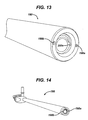
- FIG. 13 is a partial perspective view of a distal end of the surgical device of FIG. 11 ;
- FIG. 14 is a perspective view of the surgical device of FIG. 11 ;
- FIG. 15 is a side view of the surgical device of FIG. 14 ;
- FIG. 16 is a perspective view of one embodiment of a surgical device including a sheath and having a movable ring located at least partially in a distal portion of the sheath;
- FIG. 17 is a side view of the surgical device of FIG. 16 ;
- FIG. 18 is a partial perspective view of a distal end of the surgical device of FIG. 16 with the ring in a first position;
- FIG. 19 is a partial cross-sectional view of a distal end of the surgical device of FIG. 16 with the ring in a first position;
- FIG. 20 is a partial perspective view of a distal end of the surgical device of FIG. 16 with the ring in a second position;
- FIG. 21 is a partial cross-sectional view of a distal end of the surgical device of FIG. 16 with the ring in a second position;
- FIG. 22 is a partial perspective view of a distal portion of one embodiment of a surgical device including a sheath and having a movable ring located at least partially in a distal portion of the sheath with the ring positioned in a first position;
- FIG. 23 is a partial cross-sectional view of the surgical device of FIG. 22 ;
- FIG. 24 is a partial perspective view of the surgical device of FIG. 22 with the ring being rotated;
- FIG. 25 is a partial perspective view of the surgical device of FIG. 24 with the ring moved into a second position;
- FIG. 26 is a partial cross-sectional view of the surgical device of FIG. 25 .
- the methods and devices can be used in numerous surgical procedures and with numerous surgical instruments.
- the devices can be used in laparoscopic procedures, in which the device is introduced percutaneously.
- the methods and devices can also be used in open surgical procedures.
- the methods and devices disclosed herein can be used with numerous rigid and/or flexible surgical instruments.
- the surgical instrument can be a scope, e.g., an endoscope, a laparoscope, a colonoscope, an arthroscope, a gastroscope, etc., and any other type of surgical device that has a distal end that can be disposed in a body cavity and that has a viewing element configured to allow viewing of an image, such as a still or video image on a monitor or through an eyepiece.
- a scope e.g., an endoscope, a laparoscope, a colonoscope, an arthroscope, a gastroscope, etc.
- any other type of surgical device that has a distal end that can be disposed in a body cavity and that has a viewing element configured to allow viewing of an image, such as a still or video image on a monitor or through an eyepiece.
- Fluids are intended to include any substance that, when on a surgical instrument, can adversely affect the functioning of the instrument or a surgeon's ability to use it.
- Fluids include any kind of bodily fluid, such as blood, and any kind of cleaning fluid introduced during a surgical procedure, such as saline or air.
- Fluids also include fluid/solid mixtures or fluids with particles (such as pieces of tissue) suspended or located therein, as well as viscous materials and gases.
- viewing element as used herein is intended to encompass any one or more elements (e.g., a lens, a sensor, etc.) configured to allow for any type of visualization through still, moving, or other visual images and that the term “body cavity” as used herein is intended to encompass any internal body area, e.g., the abdominal cavity, the oral cavity, a body lumen, etc.
- cleaning a distal end of a surgical instrument as discussed herein is intended to include cleaning at least a portion of a distal end of a surgical instrument disposed in a sheath and/or a viewing element disposed at the surgical instrument's distal end.
- a surgical device can include a sheath having at least one lumen extending therethrough configured to allow a surgical viewing instrument to be removably or fixedly disposed therein.
- the sheath can also have a passageway extending therethrough configured to allow fluid to flow therethrough.
- the fluid conduit can be removably coupled to or integrally formed in the sheath that is disposable around the surgical instrument such that the fluid conduit can be inserted into and withdrawn from a body cavity simultaneously with the surgical instrument disposed in the sheath.
- the fluid conduit can be configured to be movable between positions that can allow alternative directions of fluid flow toward and/or away from a viewing element on the surgical instrument to help clean the viewing element and fluid flow away from the viewing element and toward a surgical field in a body cavity to help cleanse the surgical field.
- the fluid conduit can thus help clean the viewing element and/or help wash away fluid from a body cavity in which the surgical instrument's viewing element is disposed, thereby helping to maintain acceptable visual clarity through the viewing element.
- the surgical instrument can therefore be less likely to require withdrawal from the body for replacement with another, clean surgical instrument and/or for cleaning or replacement of the viewing element. In this way, a surgical procedure is less likely to be interrupted one or more times to address a visually impeded viewing element, thereby reducing the time for the surgical procedure.
- the surgical instrument By cleaning a surgical instrument's distal end while the surgical instrument is disposed in the body, the surgical instrument can substantially remain in a desired position near patient tissue of interest, and the surgeon need not take additional time to maneuver the surgical instrument back into desired position following the instrument's cleaning and/or replacement with another surgical instrument. Reducing the need to remove the surgical instrument out of the body, such as through an introducer device used to introduce the surgical instrument into or remove the surgical instrument from a body cavity, can also reduce chances of the surgical instrument drawing fluid into the introducer device that could obscure the viewing element's viewing path during its passage through the introducer device and/or upon the surgical instrument's reinsertion (or other surgical instrument's insertion) into the introducer device.
- the fluid conduit in one or both of its alternate positions can allow fluid be to suctioned away from adjacent the viewing element or from a surgical site distally beyond the viewing element, such as smoke or mist within a body cavity, which can help remove fluid that could potentially obscure vision through the viewing element or could otherwise adversely affect a surgical procedure.
- Providing fluid suction and fluid irrigation using the same sheath and fluid conduit system associated with a surgical instrument can also help reduce the amount of instrumentation needed during a surgical procedure.
- FIGS. 1-5 illustrate one exemplary embodiment of surgical device 10 including a fluid conduit, e.g., an extendable arm 44 , coupled to an annular sheath 12 .
- the surgical device 10 can be formed from any type and any combination of materials, preferably fluid-impermeable, preferably rigid and/or semi-rigid, and preferably biocompatible materials.
- the surgical device 10 can be configured with a fluid conduit as discussed below but otherwise be configured similar to surgical devices described in U.S. Patent Publication No. 2008/0081948 filed Oct. 3, 2006 entitled “Apparatus For Cleaning A Distal Scope End Of A Medical Viewing Scope” and in U.S. patent application Ser. No. 12/047,474 filed Mar.
- the surgical device 10 can include the annular sheath 12 having proximal and distal portions 16 , 18 and having a lumen 14 with open proximal and distal ends 14 a , 14 b extending therethrough.
- the lumen 14 can be configured to receive a surgical instrument such as an endoscope 20 disposed at least partially therein.
- the sheath 12 before and/or after the endoscope 20 has been disposed within the lumen 14 , can be configured to be directly inserted into a patient 22 or be inserted into the patient 22 through a working channel of an introducer device, e.g., a trocar 60 , extending into the patient's body cavity 50 .
- an introducer device e.g., a trocar 60
- the endoscope 20 can be fixedly attached to the sheath 12 , or the endoscope 20 can be removably coupled to the sheath 20 , such as by slidably disposing the endoscope 20 , distal end 42 first, into the lumen 14 through the sheath's proximal portion 16 .
- the endoscope's distal end 42 has an outside diameter.
- An inside diameter of a tubular wall 24 at the sheath's distal portion 18 can be less than the outside diameter of the endoscope's distal end 42 to help hold the endoscope 20 within the lumen 14 and to help prevent the endoscope 20 from sliding distally beyond the sheath's distal end 40 . As shown in FIGS.
- the endoscope's distal end 42 can make a press fit with the sheath 12 at the sheath's distal portion 18 .
- the press fit can be accomplished in any way appreciated by a person skilled in the art, such as by varying the diameter of the lumen 14 such that the inside diameter of the tubular wall 24 tapers from the sheath's proximal end 52 to the sheath's distal end 40 or tapers along any portion thereof.
- the endoscope 20 can be coupled to the sheath 12 in any way appreciated by a person skilled in the art, e.g., by using an elastomeric sheath, a compression fitting, an elastomeric O-ring attached to the sheath 12 proximate the sheath's distal end 40 and configured to attachingly engage the endoscope 20 which has been inserted into the sheath's proximal end 52 , etc.
- the sheath 12 has a tubular wall 24 , which has inside and outside diameters and contains a passageway 26 between the inside and outside diameters.
- the inside diameter of the tubular wall 24 is defined by the diameter of the lumen 14
- the outside diameter of the tubular wall 24 is defined by an outside diameter of the sheath 12 .
- the passageway 26 has open proximal and distal portions 28 , 30 configured to allow a fluid to flow therethrough. At least between the proximal and distal portions 28 , 30 , the passageway 26 can be substantially aligned with a longitudinal axis A 2 of the sheath 12 .
- the proximal portion 28 of the passageway 26 has an opening that can be fluidly coupled to at least one of a fluid irrigation source 32 and a fluid vacuum source 34 as discussed further below.
- the distal portion 30 of the passageway 26 has at least two openings that can alternatively serve as a distal end opening of the passageway 26 through adjustment of a fluid conduit as discussed further below.
- the distal portion 18 of the sheath 12 has an annular manifold 36 , illustrated in FIG. 3 , which includes at least one proximal orifice 38 located in the distal portion 18 of the sheath 12 and proximal to a distal end 40 of the sheath 12 and preferably directed substantially toward the lumen 14 , and more preferably directed substantially toward a position of a distal end 42 of the endoscope 20 disposed in the lumen 14 .
- fluid flowing through the passageway 26 can be configured to be in fluid communication with the lumen 14 and/or with the endoscope's distal end 42 in the lumen 14 .
- fluid flowing out of the proximal orifice 38 can clean inside the lumen 14 and/or clean the endoscope's distal end 42 , and hence also a viewing element at the endoscope's distal end 42 .
- allowing fluid to flow into the proximal orifice 38 e.g., in a proximal direction through the passageway 26
- can draw fluid away from inside the lumen 14 and/or from the endoscope's distal end 42 Two proximal orifices 38 are shown in FIGS. 1 , 2 , and 4
- four proximal orifices 38 are shown in FIG.
- the passageway 26 can have any number of proximal orifices, and each proximal orifice can optionally include a plurality of circumferentially spaced apart orifices.
- the annular manifold 36 can have a volume greater than a total volume of passages 37 between the manifold 36 and each of the proximal orifices 38 .
- the passages 37 are portions of the passageway 26 extending to the proximal orifices 38 such that the passages 37 are portions of the passageway 26 prevented from having fluid flow therein when the arm 44 is in the second, distal position.
- a plurality of proximal orifices 38 can be substantially axially aligned along a cross-sectional axis A 1 of the sheath 12 , as shown in FIGS. 1 , 2 , and 4 , or one or more proximal orifices 38 can be substantially non-axially aligned from any one or more other proximal orifices 38 such that at least two of the orifice(s) 38 are axially aligned with different cross-sectional axes of the sheath 12 .
- the passages 37 are preferably substantially parallel to the cross-sectional axis A 1 , although each of the passages 37 can be linear or non-linear (same or different from any of the other passages 37 ).
- the sheath's distal portion 18 can have a circumferentially inner surface 54 containing the proximal orifice 38 . Fluid can tend to adhere to the circumferentially inner surface 54 , thereby helping to keep fluid off and away from the endoscope's distal end 42 and outside a viewing path of a viewing element at the endoscope's distal end 42 .
- the circumferentially inner surface 54 of the sheath's distal portion 18 can longitudinally extend from the sheath's distal end 40 to the endoscope's distal end 42 , as seen in FIG. 1 .
- the passageway 26 can be configured to receive a fluid conduit, e.g., the extendable arm 44 , disposed therein through which fluid can flow.
- the arm 44 has an outer diameter that is less than the diameter of the passageway 26 such that the arm 44 can slidably move within the passageway 26 .
- the arm 44 can be rigid and/or flexible, but the arm 44 is preferably rigid enough to help move the arm 44 through the passageway 26 and to help penetrate a seal 62 as discussed below. However, the arm 44 is also preferably flexible enough to help the arm 44 navigate any curves, bens, twists, etc. in the passageway 26 .
- the arm 44 preferably has a constant cross-sectional area, at least in a fluid-carrying portion of the arm 44 configured to be disposable within the passageway 26 , to help reduce flow losses and provide better response times for fluid flowing through the arm 44 .
- the arm 44 also preferably has a cross-sectional shape that substantially matches the passageway's cross-sectional shape, e.g., circular, elliptical, crescent-shaped, etc., to help smoothly pass the arm 44 through the passageway 26 .
- an open distal end 46 of the extendable arm 44 is located proximal to the passageway's proximal orifice 38 such that fluid flowing through the arm's distal end 46 is in fluid communication with the proximal orifice 38 such that fluid can flow through the passageway 26 and the proximal orifice 38 .
- the arm 44 can be axially adjustable, e.g., adjustable substantially parallel to the longitudinal axis A 2 .
- Advancing the arm 44 distally can advance at least a portion of the arm 44 including at least the arm's distal end 46 through the seal 62 located between the proximal orifice 38 and the sheath's distal end 40 .
- the arm's distal end 46 can be substantially linear, as shown in FIGS. 1 and 4 , or the distal end 46 can be non-linear, e.g., curved, conical, etc., to help the arm 44 “break” the seal 62 and/or to help increase a rate or pressure of fluid flowing distally through the distal end 46 .
- the arm's distal end 46 is located distal to the proximal orifice 38 such that fluid is prevented from flowing through the proximal orifice 38 and instead can flow through the arm's distal end 46 and through at least one distal orifice 48 in the sheath 12 .
- the passageway 26 can include any number of distal orifices, and each distal orifice can optionally include a plurality of circumferentially spaced apart orifices.
- the arm 44 can extend distally beyond the sheath's distal end 40 such that fluid flowing through the passageway 26 can flow through the arm 44 and does not contact the passageway's inner wall, as shown in FIG. 4 .
- the arm 44 can be advanced through the seal 62 a distance that allows the seal 62 to be “broken” or penetrated but that keeps the arm's distal end 46 contained within the sheath 12 , e.g., located proximal to the sheath's distal orifice 48 and between the seal 62 and the sheath's distal end 40 .
- the sheath 12 can include a stop element in its distal portion 18 to help prevent the arm 44 from being distally advanced beyond the sheath's distal end 40 and to help reduce chances of the arm 44 interfering with a surgical site beyond the sheath's distal end 40 .
- the stop element include a fluid-permeable mesh disposed over the sheath's distal orifice 48 , a lip around the sheath's distal orifice, a diameter of the passageway 26 in at least a portion of the passageway 26 distal to the seal 62 that is smaller than a diameter of the arm 44 similar to that described above regarding the endoscope 20 in the lumen 14 , etc.
- the distal orifice 48 is preferably formed in the sheath's distal end 40 to maximize flow of fluid beyond the sheath's distal end 40 , but the distal orifice 48 can be at any location in the sheath 12 that can allow fluid flowing through the passageway 26 to be in fluid communication with the body cavity 50 in which at least part of the distal portion 18 of the sheath 12 is disposed, e.g., in a side of the sheath 12 .
- the seal 62 can include any one or more fluid seals alone or in combination as will be appreciated by a person skilled in the art.
- the seal 62 can include a zero-closure seal and/or an instrument seal, e.g., a duckbill seal, a flapper valve, a flapper door, a gel pad seal, an overlapping multi-layer seal, etc.
- the seal 62 is configured to be self-sealing such that the arm 44 can be distally advanced through the seal 62 to penetrate the seal 62 and can be proximally moved through the seal 62 to “re-seal” the seal 62 .
- the seal 62 can be configured for one-time use such that distally advancing the arm 44 breaks the seal 62 and proximally moving the arm 44 to a position proximal of the seal 62 does not allow for “re-sealing” of the seal 62 .
- the arm 44 can be configured to engage the passageway 26 , such as by having corresponding mating threads, grooves, or other engagement mechanism(s) on an inner surface of the passageway 26 and on an outer surface of the arm 44 .
- Such an engagement mechanism can help hold the arm 44 in a desired position within the passageway 26 and/or help guide the arm 44 smoothly through the passageway 26 .
- the arm 44 can include a locking mechanism, preferably at its proximal end 58 where it can be manipulated outside the patient 22 , configured to hold the arm 44 in a desired position within the passageway 26 .
- the locking mechanism include tabs, corresponding depressions and protrusions on the sheath 12 and the arm 44 that allow for successive positions of the arm 44 within the passageway 26 , etc.
- the arm 44 can be moved between the first and second positions in a variety of ways.
- the arm 44 can be moved by manually manipulating a handle 56 at the arm's proximal end 58 .
- the handle 56 can have any size, shape, and configuration and is preferably configured to at least partially extend outside the patient 22 when at least a portion of the sheath 12 is disposed in the patient's body cavity 50 .
- the handle 56 can be pushed distally to distally advance the arm 44 , thereby moving the arm 44 from the first position to the second position.
- the handle 56 can be pulled proximally to proximally retract the arm 44 , thereby moving the arm 44 from the second position to the first position.
- the handle 56 can include mechanical and/or electrical components.
- the handle 56 can be configured to abut the proximal end 52 of the sheath 12 to help prevent the arm 44 from being entirely disposed within the passageway 26 .
- the handle 56 can have a maximum diameter greater than a diameter of the passageway 26 , at least at the second lumen's proximal portion 28 , so that a distal surface of the handle 56 can abut the sheath's proximal portion 28 without sliding into the passageway 26 .
- the arm 44 can be configured to move in another way, such as through manipulation of a button, a lever, and/or other control in mechanical and/or electronic communication with the arm 44 such that the arm 44 can move when the control is manipulated, e.g., pushed, pulled, switched, etc.
- the device 10 can also include a fluid system 64 configured to provide a fluid irrigation source and/or fluid evacuation source to the sheath 12 , and more particularly to the fluid passageway 26 and the arm 44 disposed in the passageway 26 .
- the fluid system 64 can include the irrigation source 32 , the vacuum source 34 , a handpiece 66 having a fluid outlet 68 , and a flexible fluid flow tube 70 having proximal and distal tube ends 72 , 74 .
- the distal tube end 74 can be coupled to the sheath 12 to be in fluid communication with the proximal portion 28 of the passageway 26 , and more particularly to the arm 44 in the proximal portion 28 of the passageway 26 .
- the arm 44 can be coupled to the tube 70 through a sidewall of the sheath 12 , as shown in FIGS. 1 and 4 .
- the arm 44 can be coupled to the tube 70 proximal to the proximal end 52 of the sheath 12 , such as through the arm's handle 56 .
- the proximal tube end 48 can be coupled to the handpiece 66 to be in fluid communication with the fluid outlet 68 .
- the handpiece 66 includes first and second fluid inlets 76 , 78 , with the first fluid inlet 76 fluidly coupled, e.g., via first tubing 80 , to the irrigation source 32 , and the second fluid inlet 78 fluidly coupled, e.g., via second tubing 82 , to the vacuum source 34 .
- the irrigation source 32 can include any one or more types of fluid (liquid and/or gas).
- the vacuum source 34 can provide any one or more of a full vacuum, a partial vacuum, and aspiration. A vacuum provided by the vacuum source 34 is relative to the pressure at the distal opening of the passageway 26 , whether the distal opening is located at the proximal orifice 38 or the distal orifice 48 .
- the vacuum source 34 can be ambient room air when the passageway's distal opening is exposed to a higher pressure within, e.g., the insufflated abdomen of a patient.
- one or more additives e.g., an anti-fogging agent such as a surfactant, can be added to fluid in one or more of the sources 32 , 34 , to fluid flowing through one or both of the tubings 80 , 82 , and/or through the tube 70 .
- the irrigation source 32 can include an operating-room saline bag, the first tubing 80 being fluidly connected to the bag, and the vacuum source 34 can include an operating-room suction canister, the second tubing 82 being fluidly connected to the canister.
- a bladder can optionally be placed around the saline bag to increase pressure of the irrigation fluid.
- the handpiece 66 can be configured to alternatively switch between the irrigation source 32 and the vacuum source 34 , such as by using first and second valve buttons 84 , 86 .
- fluid can flow proximally or distally through the passageway 26 to, respectively, provide fluid aspiration and irrigation.
- Pushing or otherwise actuating the first valve button 84 can fluidly connect the first fluid inlet 76 to the fluid outlet 68
- pushing or otherwise actuating the second valve button 86 can fluidly connect the second fluid inlet 78 to the fluid outlet 46 .
- a “Y” passageway 88 can fluidly connect the first and second fluid inlets 76 , 78 to the fluid outlet 68 .
- the first valve button 84 is operatively connected to a first valve 90 disposed in a first arm 92 of the “Y” passageway 88 .
- the second valve button 86 is operatively connected to a second valve 94 disposed in a second arm 96 of the “Y” passageway 88 .
- Such as “Y” passageway configuration can allow for user-selectable fluid flow configurations that allow the fluid outlet 68 to be in fluid communication with one but not the other of the fluid inlets 76 , 78 at any given time (or with neither of the fluid inlets 76 , 78 ).
- Various valve configurations are described in more detail in U.S. Patent Publication No. 2008/0081948 and U.S. patent application Ser. No. 12/047/474, both mentioned above.
- FIG. 6 illustrates another embodiment of a surgical device 10 ′ that can be used to irrigate and/or aspirate a distal end 42 ′ of an endoscope 20 ′ and/or a body cavity 50 ′.
- the endoscope 20 ′ is disposed in a lumen 14 ′ of a sheath 12 ′.
- a protective lens 100 that can attach to the sheath 12 ′, preferably fixedly although it can be removably attached.
- the lens 100 closes off the sheath 12 ′ proximate to the sheath's distal end 40 ′ by effectively closing off the lumen 14 ′ proximate to the lumen's distal end 14 b ′.
- the endoscope 20 ′ is insertable into the sheath's proximal portion 16 ′ with its distal end 42 ′ disposed proximate to the lens 100 .
- the lumen 14 ′ is tapered in this illustrated embodiment, and given the size of the endoscope 20 ′ disposed therein, the endoscope 20 ′ is prevented from contacting the lens 100 , but another surgical instrument disposed in the lumen 14 ′ can be configured to contact a proximal surface 104 of the lens 100 .
- a distal surface 102 of the lens 100 helps protect the endoscope's distal end 42 ′ and be in fluid communication with a proximal orifice 38 ′ of a fluid passageway 26 ′ such that when the proximal orifice 38 ′ defines a distal opening of the passageway 26 ′ based on a position of an arm 44 ′ disposed in the passageway 26 ′, fluid flowing through the proximal orifice 38 ′ can help clean the distal surface 102 of the lens 100 .
- the lens 100 can be optically clear and can be a non-magnifying or a magnifying lens.
- FIG. 7 illustrates another embodiment of an annular sheath 110 having a lumen 112 extending therethrough in which a surgical instrument (not shown) can be disposed.
- the sheath 110 also has a fluid passageway 114 formed in the sheath's tubular wall 122 through which fluid can flow between a proximal opening of the passageway (not shown) and a distal opening of the passageway 114 .
- the distal opening can either include a proximal orifice 116 , which is substantially directed at the distal end 124 of the lumen 112 where a distal end of a surgical instrument can be positioned in the lumen 112 , or a distal orifice 118 , substantially directed beyond a distal end 120 of the sheath 110 .
- the proximal orifice 116 or the distal orifice 118 can thus be selectively chosen as the passageway's 114 distal opening depending on a position of an extendable arm (not shown) disposed within the passageway 114 .
- a proximal orifice passageway 126 between the sheath's passageway 114 and the proximal orifice 116 can taper, as shown in FIG. 7 , to help increase a rate and/or pressure of fluid flowing out of the proximal orifice 116 when fluid is flowing in a distal direction indicated by arrow 128 , although the proximal orifice passageway 126 can have any configuration.
- the proximal orifice 116 has a portion abutting the lumen's distal end 124 and a portion spaced apart from the lumen's distal end 124 .
- a portion of the tubular wall 122 defines the distal end 124 of the lumen 112 such that the tubular wall 122 forms a stop element in the form of a lip or shelf that can contact a distal surface of a surgical instrument disposed within the lumen 112 and prevent further distal movement of the surgical instrument through the sheath 110 .
- the tubular wall 122 can include an annular manifold, discussed above, and the stop element can be a part of the manifold.
- the lumen 112 and the tubular wall 122 are thereby configured to allow a distal end of a surgical instrument disposed in the lumen 112 to contact the lumen's distal end 124 and abut a portion of the tubular wall 122 .
- fluid when fluid is configured to flow through the proximal orifice 116 , fluid can be irrigated or suctioned substantially to or from the surgical instrument's distal end.
- FIG. 8 illustrates another embodiment of an annular sheath 130 including proximal and distal sections 132 , 134 .
- the distal section 134 is coupled to the proximal section 132 and is manually expandable and rotatable with respect to the proximal section 132 of the sheath 130 , although in other embodiments the rotation and/or expansion can be mechanically and/or electronically actuated.
- the proximal and distal sections 132 , 134 are coupled with a rotatable tongue 136 (rotatable about a central longitudinal axis 144 ) and an at-least-partially-annular groove 138 arrangement.
- At least one locking tab 140 formed on each of the proximal and distal sections 132 , 134 can abut each other during extension of the distal section 134 with respect to the proximal section 132 to help prevent separation of the distal section 134 from the proximal section 132 .
- a seal member 135 can be coupled to the proximal and distal sections 132 , 134 and be disposed in a fluid passageway 137 of the sheath 130 to help fluidly seal the passageway 137 during extension of the distal section 134 so fluid can flow through the passageway 137 between the proximal and distal sections 132 , 134 .
- a distal end of a surgical instrument disposed in a lumen 146 of the sheath 130 can be angled for improved sideways viewing, the distal section can be correspondingly angled, and the rotatable feature can allow rotational alignment of the angled distal section with the angled distal end of the surgical instrument.
- a stop element 142 at a distal end of the lumen 146 in this embodiment is shown as a portion of the distal section 134 .
- Surgical instruments can vary a small amount (such as one inch) in length, and the extendable and retractable distal section 134 can allow surgical instruments of varying length to be fully inserted in the sheath 130 against the stop element 142 .
- FIGS. 9 and 10 illustrate another exemplary embodiment of a surgical device 150 including a fluid conduit in the form of an extendable arm 152 disposed in a passageway 154 of an annular sheath 156 .
- FIG. 9 illustrates the arm 152 in a first, distal position where the arm's distal end 158 is disposed proximal to a seal 160 in the passageway 154 such that fluid can flow through a proximal orifice 162 .
- FIG. 9 illustrates the arm 152 in a first, distal position where the arm's distal end 158 is disposed proximal to a seal 160 in the passageway 154 such that fluid can flow through a proximal orifice 162 .
- FIG. 10 illustrates the arm 152 in a second, proximal position where the arm 152 has been pushed distally so the arm's distal end 158 has passed distally beyond the seal 160 such that fluid can flow through the arm's distal end 158 and beyond the sheath's distal end 164 .
- Flow of fluid through the arm 152 can be controlled through manipulation of a trumpet valve 166 .
- the trumpet valve 166 can be coupled to a proximal portion 168 of the sheath 156 to help allow for manipulation of the trumpet valve 166 outside a patient's body when at least a portion of the device 150 is disposed in a patient.
- the trumpet valve 166 can be actuated using a button 168 configured to control flow of fluid through the trumpet valve's handle 170 and hence also through the passageway 154 .
- FIGS. 11-15 illustrate still an exemplary embodiment of a surgical device 180 that includes a plurality of fluid conduits, e.g., a plurality of extendable arms. Having a plurality of extendable arms can allow the device 180 to provide fluid irrigation and/or fluid suction to a larger area.
- an annular sheath 182 includes first and second passageways 184 a , 184 b configured to respectively receive first and second extendable arms 186 a , 186 b . Although two passageways are shown in the sheath 182 , the sheath 182 can include any number of passageways.
- the sheath 182 also includes a lumen 192 extending therethrough in which a surgical instrument 194 can be disposed.
- FIG. 11 shows the arms 186 a , 186 b in a first, distal position in which fluid can flow through the first and second arms 186 a , 186 b and respectively through proximal orifices 200 a , 200 b that are formed in the sheath 182 proximal to the sheath's distal end 196 .
- FIG. 12 shows the arms 186 a , 186 b in a second, proximal position where distal ends 188 a , 188 b of the arms 186 a , 186 b have broken respective seals 190 a , 190 b and extend beyond a distal end 196 of the sheath 182 .
- the sheath's distal end 196 can include formed therein first and second distal holes 198 a , 198 b , shown in FIGS. 13 and 14 , through which the first and second arms 186 a , 186 b can respectively extend when in the second position or that fluid can directly flow through if the arms 186 a , 186 b are not distally advanced far enough in the second position to pass through the holes 198 a , 198 b .
- the holes 198 a , 198 b , and hence also the arms 186 a , 186 b , are equidistantly spaced around the sheath's distal circumference in this embodiment, but the holes 198 a , 198 b and the arms 186 a , 186 b can be spaced at any interval(s) in the sheath.
- the first and second arms 186 a , 186 b can each be configured for fluid irrigation and for fluid suction, or the arms 186 a , 186 b can be individually dedicated such that one arm can be configured for fluid irrigation while the other can be configured for fluid suction. If the arms 186 a , 186 b are configured to each provide fluid irrigation and fluid suction, the arms 186 a , 186 b can be configured for simultaneous movement, e.g., manipulated using a single handle or other movement actuator controlling both arms 186 a , 186 b , or they can be configured for individual manipulation.
- the arms 186 a , 186 b can be fluidly coupled to the same fluid irrigation source and the same fluid vacuum source, or each of the arms 186 a , 186 b can have its own dedicated irrigation source and/or vacuum source. If the arms 186 a , 186 b are individually dedicated, one of the arms can be fluidly coupled to a fluid irrigation source while the other arm can be fluidly coupled to a fluid vacuum source.
- Individually dedicating the arms 186 a , 186 b can help reduce chances that fluid used for irrigation contains any undesirable, previously suctioned fluid because any previously suctioned fluid will not be in the arm used to provide fluid irrigation and thus cannot be undesirably mixed into the irrigation fluid. Individually dedicating the arms 186 a , 186 b can also allow for fluid to wash a desired area and be quickly aspirated with simultaneous fluid irrigation and fluid suction.
- FIGS. 16-21 illustrate another exemplary embodiment of surgical device 210 including a fluid conduit, e.g., a rotatable ring or an adjustable cap 212 , coupled to an annular sheath 214 .
- the surgical device 210 is similar to the surgical devices discussed above, and similarly named elements in various embodiments discussed herein can be similarly configured.
- the sheath 214 has proximal and distal portions 216 , 218 and has a lumen 220 extending therethrough that is configured to receive a surgical instrument, e.g., an endoscope 222 , disposed therein.
- the sheath 214 also has at least one passageway extending therethrough that is formed within the sheath's tubular wall 226 and is configured to allow fluid to flow therethrough.
- First and second passageways 224 a , 224 b are illustrated in this embodiment, but the sheath 214 can have two or any other number of passageways. Proximal portions of each of the passageways 224 a , 224 b can be fluidly coupled to at least one of a fluid irrigation source and a fluid vacuum source through one or more tubes 236 coupled to the sheath 214 as discussed above such that fluid can flow proximally and/or distally through the passageways 224 a , 224 b.
- the cap 212 can be disposed at the sheath's distal portion 218 , preferably extending a distance proximally from the sheath's distal end 228 , and be either fixedly removably coupled to the sheath 214 .
- the cap's shape substantially conforms to the shape of the sheath 214 , although the cap 212 can have any shape, and the cap 212 can have any size.
- the cap 212 can be configured to be movable between at least two positions to change locations of distal openings of the passageways 224 a , 224 b . When the cap 212 is in a first, proximal position, shown in FIGS.
- the distal openings of the first and second passageways 224 a , 224 b include proximal orifices 226 such that fluid flowing through the first and second passageways 224 a , 224 b can be in fluid communication with the proximal orifices 226 .
- proximal orifices 226 are illustrated in this embodiment, the sheath 214 can include any number of proximal orifices.
- the proximal orifices 226 are located proximal to the sheath's distal end 228 and are preferably directed substantially toward the lumen 220 , and more preferably directed substantially toward a position of a distal end 230 of the endoscope 222 disposed in the lumen 220 .
- the cap 212 can be moved between the first, proximal position and a second, distal position, shown in FIGS. 20 and 21 .
- the cap 212 In the second, distal position, the cap 212 covers the proximal orifices 226 , such that the proximal orifices 226 are fluidly sealed, and allows the distal openings of the first and second passageways 224 a , 224 b to include at least one distal orifice 232 in the sheath 214 such that fluid flowing through the first and second passageways 224 a , 224 b is prevented from flowing through the proximal orifices 226 and can instead be in fluid communication with the distal orifices 232 .
- the cap 212 when the cap 212 is in the first position, the cap 212 covers the distal orifices 232 and uncovers the proximal orifices 226 .
- the sheath 214 can include any number of distal orifices. Furthermore, each distal orifice can optionally include a plurality of circumferentially spaced apart orifices.
- the first position is preferably the cap's default, initial position, but either the first or second positions can be the cap's default, initial position.
- the cap 212 can be moved between the first and second positions in a variety of ways.
- the cap's movement is preferably from a location proximal to the cap 212 , and more preferably from a location configured to be outside a patient's body when at least the distal portion 218 of the sheath 214 is disposed in a patient.
- the cap 212 can be at least partially rotatable in a clockwise direction and/or a counter-clockwise direction substantially around a central, longitudinal axis 234 of the cap 212 .
- the cap 212 can move between a plurality of positions in any one or more other ways, such as through linear movement substantially parallel to the cap's central axis 234 .
- the cap's rotation can be manually, electrically, or otherwise effectuated as will be appreciated by a person skilled in the art.
- Rotating the cap 212 in one direction can expose the proximal orifices 226 to the passageways 224 a , 224 b for fluid communication between the two and can cover the distal orifices 232 to prevent fluid communication between the distal orifices 232 and the passageways 224 a , 224 b , while rotating the cap 212 in an opposite direction, e.g., counter-clockwise, can expose the distal orifices 232 to the passageways 224 a , 224 b and cover the proximal orifices 226 .
- rotating the cap 212 as far as possible in a particular direction fully exposes the desired orifices and fully covers the other, undesired orifices such that it can be more easily apparent when the cap 212 is in a desired position to expose a desired distal opening of the passageways 224 a , 224 b because the cap's rotational movement in that direction ceases.
- the cap 212 can be rotatable in one or both of the clockwise and counter-clockwise directions and have at least two locked positions within its range of rotational motion. At least one locked position can correspond to the first, distal position, and at least one locked position can correspond to the second, proximal position.
- One or more stop elements e.g., a groove, a tab, corresponding protrusions and depressions, etc., formed on or in the sheath 214 can be configured for engagement with the cap 212 such that the cap 212 can “catch” the stop element(s) during its rotation to help temporarily lock the cap 212 in one of the first and second positions and such that the cap 212 can be released from the stop element(s) to move to another position.
- stop elements e.g., a groove, a tab, corresponding protrusions and depressions, etc.
- the cap 212 is movable between positions, movement of the cap 212 to selectively expose and cover orifices in the sheath's distal portion 218 can help create a scrubbing effect adjacent one or more of the orifices because movement of a solid surface of the cap 212 over an orifice can help scrub away or unclog fluid that may have built up at the orifice during previous fluid irrigation and/or suction through the orifice.
- FIGS. 22-26 illustrate another exemplary embodiment of a surgical device 250 that has a fluid conduit in the form of an adjustable cap 252 that can selectively expose and cover four proximal orifices 254 and four distal orifices 256 .
- the cap 252 is shown in a first, proximal position in FIGS. 22 and 23 where fluid can flow through a passageway 258 having its distal opening at the proximal orifices 254 .
- the passageway 258 in this embodiment is illustrated as a single passageway formed in the device's annular sheath 260 such that the cap 252 acts as a manifold allowing fluid to flow through a plurality of distal openings formed in the cap 252 .
- the cap 252 can be configured to rotate, e.g., clockwise as illustrated by directional arrows in FIG. 24 , to redirect fluid flow through the passageway 258 by covering the proximal orifices 254 and exposing the distal orifices 256 as shown with the cap 252 moved into a second, distal position in FIGS. 24 and 25 .
- the proximal orifices 254 and the distal orifices 256 can both be at least partially exposed, as illustrated in FIG. 24 .
- the cap 252 can be configured to allow fluid to flow through the passageway 258 and both distal openings 254 , 256 to allow for multi-directional fluid flow at and beyond the sheath's distal portion 262 .
- the proximal and distal orifices 254 , 256 and corresponding openings in the cap 252 that can expose the proximal and distal orifices 254 , 256 have adequate space between them to prevent the proximal orifices 254 from being exposed when the distal orifices 256 are exposed, and vice versa.
- the device disclosed herein can also be designed to be disposed of after a single use, or it can be designed to be used multiple times. In either case, however, the device can be reconditioned for reuse after at least one use. Reconditioning can include any combination of the steps of disassembly of the device, followed by cleaning or replacement of particular pieces and subsequent reassembly. In particular, the device can be disassembled, and any number of the particular pieces or parts of the device can be selectively replaced or removed in any combination. Upon cleaning and/or replacement of particular parts, the device can be reassembled for subsequent use either at a reconditioning facility, or by a surgical team immediately prior to a surgical procedure.
- reconditioning of a device can utilize a variety of techniques for disassembly, cleaning/replacement, and reassembly. Use of such techniques, and the resulting reconditioned device, are all within the scope of the present application.
Abstract
Description
Claims (21)
Priority Applications (10)
| Application Number | Priority Date | Filing Date | Title |
|---|---|---|---|
| US12/172,349 US8915842B2 (en) | 2008-07-14 | 2008-07-14 | Methods and devices for maintaining visibility and providing irrigation and/or suction during surgical procedures |
| JP2009164371A JP5399149B2 (en) | 2008-07-14 | 2009-07-13 | Surgical equipment |
| CN2009101402576A CN101627894B (en) | 2008-07-14 | 2009-07-13 | Devices for maintaining visibility and providing irrigation and/or suction during surgical procedures |
| CA2671694A CA2671694C (en) | 2008-07-14 | 2009-07-14 | Methods and devices for maintaining visibility and providing irrigation and/or suction during surgical procedures |
| AT09251789T ATE555713T1 (en) | 2008-07-14 | 2009-07-14 | DEVICES FOR MAINTAINING VISIBILITY AND PROVIDING IRRATION AND/OR SUCTION DURING OPERATIONAL PROCEDURES |
| EP09251789A EP2145578B1 (en) | 2008-07-14 | 2009-07-14 | Devices for maintaining visibility and providing irrigation and / or suction during surgical procedures |
| US12/712,276 US9005116B2 (en) | 2006-04-05 | 2010-02-25 | Access device |
| US14/683,306 US20150209025A1 (en) | 2006-04-05 | 2015-04-10 | Access Device |
| US15/207,133 US20160317184A1 (en) | 2006-04-05 | 2016-07-11 | Access Device |
| US15/469,040 US20170215919A1 (en) | 2006-04-05 | 2017-03-24 | Access Device |
Applications Claiming Priority (1)
| Application Number | Priority Date | Filing Date | Title |
|---|---|---|---|
| US12/172,349 US8915842B2 (en) | 2008-07-14 | 2008-07-14 | Methods and devices for maintaining visibility and providing irrigation and/or suction during surgical procedures |
Publications (2)
| Publication Number | Publication Date |
|---|---|
| US20100010310A1 US20100010310A1 (en) | 2010-01-14 |
| US8915842B2 true US8915842B2 (en) | 2014-12-23 |
Family
ID=41110776
Family Applications (1)
| Application Number | Title | Priority Date | Filing Date |
|---|---|---|---|
| US12/172,349 Active 2033-04-10 US8915842B2 (en) | 2006-04-05 | 2008-07-14 | Methods and devices for maintaining visibility and providing irrigation and/or suction during surgical procedures |
Country Status (6)
| Country | Link |
|---|---|
| US (1) | US8915842B2 (en) |
| EP (1) | EP2145578B1 (en) |
| JP (1) | JP5399149B2 (en) |
| CN (1) | CN101627894B (en) |
| AT (1) | ATE555713T1 (en) |
| CA (1) | CA2671694C (en) |
Cited By (274)
| Publication number | Priority date | Publication date | Assignee | Title |
|---|---|---|---|---|
| US20150087911A1 (en) * | 2013-09-26 | 2015-03-26 | Gyrus Acmi, Inc. D.B.A Olympus Surgical Technologies America | Endoscope sheath deflection devices |
| WO2018034969A1 (en) | 2016-08-16 | 2018-02-22 | Ethicon Llc | Surgical tool positioning based on sensed parameters |
| WO2018034972A1 (en) | 2016-08-16 | 2018-02-22 | Ethicon Llc | Surgical tool positioning based on sensed parameters |
| US9943377B2 (en) | 2016-08-16 | 2018-04-17 | Ethicon Endo-Surgery, Llc | Methods, systems, and devices for causing end effector motion with a robotic surgical system |
| US9956050B2 (en) | 2016-08-16 | 2018-05-01 | Ethicon Endo-Surgery, Llc | Methods, systems, and devices for controlling a motor of a robotic surgical system |
| US9968412B2 (en) | 2016-08-16 | 2018-05-15 | Ethicon Endo-Surgery, Llc | Methods, systems, and devices for controlling a motor of a robotic surgical system |
| US10016246B2 (en) | 2016-08-16 | 2018-07-10 | Ethicon Llc | Methods, systems, and devices for controlling a motor of a robotic surgical system |
| US10045827B2 (en) | 2016-08-16 | 2018-08-14 | Ethicon Llc | Methods, systems, and devices for limiting torque in robotic surgical tools |
| US10080622B2 (en) | 2016-08-16 | 2018-09-25 | Ethicon Llc | Robotics tool bailouts |
| US20180289248A1 (en) * | 2017-04-06 | 2018-10-11 | Everich Biotecology Corporation | Cleaning structure for endoscope lens |
| US10111719B2 (en) | 2016-08-16 | 2018-10-30 | Ethicon Llc | Control of the rate of actuation of tool mechanism based on inherent parameters |
| US10182875B2 (en) | 2016-08-16 | 2019-01-22 | Ethicon Llc | Robotic visualization and collision avoidance |
| US10231775B2 (en) | 2016-08-16 | 2019-03-19 | Ethicon Llc | Robotic surgical system with tool lift control |
| US10363035B2 (en) | 2016-08-16 | 2019-07-30 | Ethicon Llc | Stapler tool with rotary drive lockout |
| US10390895B2 (en) | 2016-08-16 | 2019-08-27 | Ethicon Llc | Control of advancement rate and application force based on measured forces |
| US10413373B2 (en) | 2016-08-16 | 2019-09-17 | Ethicon, Llc | Robotic visualization and collision avoidance |
| US10433925B2 (en) | 2016-08-16 | 2019-10-08 | Ethicon Llc | Sterile barrier for robotic surgical system |
| US10478256B2 (en) | 2016-08-16 | 2019-11-19 | Ethicon Llc | Robotics tool bailouts |
| US10500000B2 (en) | 2016-08-16 | 2019-12-10 | Ethicon Llc | Surgical tool with manual control of end effector jaws |
| US10531929B2 (en) | 2016-08-16 | 2020-01-14 | Ethicon Llc | Control of robotic arm motion based on sensed load on cutting tool |
| US10543018B2 (en) | 2015-05-15 | 2020-01-28 | Covidien Lp | Surgical access device |
| US10675103B2 (en) | 2016-08-16 | 2020-06-09 | Ethicon Llc | Robotics communication and control |
| US10687904B2 (en) | 2016-08-16 | 2020-06-23 | Ethicon Llc | Robotics tool exchange |
| US10709511B2 (en) | 2016-08-16 | 2020-07-14 | Ethicon Llc | Control of jaw or clamp arm closure in concert with advancement of device |
| US10813703B2 (en) | 2016-08-16 | 2020-10-27 | Ethicon Llc | Robotic surgical system with energy application controls |
| US10849698B2 (en) | 2016-08-16 | 2020-12-01 | Ethicon Llc | Robotics tool bailouts |
| US10993760B2 (en) | 2016-08-16 | 2021-05-04 | Ethicon, Llc | Modular surgical robotic tool |
| US11246670B2 (en) | 2016-08-16 | 2022-02-15 | Cilag Gmbh International | Modular surgical robotic tool |
| US11253254B2 (en) | 2019-04-30 | 2022-02-22 | Cilag Gmbh International | Shaft rotation actuator on a surgical instrument |
| US11266409B2 (en) | 2014-04-16 | 2022-03-08 | Cilag Gmbh International | Fastener cartridge comprising a sled including longitudinally-staggered ramps |
| US11266406B2 (en) | 2013-03-14 | 2022-03-08 | Cilag Gmbh International | Control systems for surgical instruments |
| US11266410B2 (en) | 2011-05-27 | 2022-03-08 | Cilag Gmbh International | Surgical device for use with a robotic system |
| US11272928B2 (en) | 2005-08-31 | 2022-03-15 | Cilag GmbH Intemational | Staple cartridges for forming staples having differing formed staple heights |
| US11278279B2 (en) | 2006-01-31 | 2022-03-22 | Cilag Gmbh International | Surgical instrument assembly |
| US11284953B2 (en) | 2017-12-19 | 2022-03-29 | Cilag Gmbh International | Method for determining the position of a rotatable jaw of a surgical instrument attachment assembly |
| US11291441B2 (en) | 2007-01-10 | 2022-04-05 | Cilag Gmbh International | Surgical instrument with wireless communication between control unit and remote sensor |
| US11291451B2 (en) | 2019-06-28 | 2022-04-05 | Cilag Gmbh International | Surgical instrument with battery compatibility verification functionality |
| US11291447B2 (en) | 2019-12-19 | 2022-04-05 | Cilag Gmbh International | Stapling instrument comprising independent jaw closing and staple firing systems |
| US11298132B2 (en) | 2019-06-28 | 2022-04-12 | Cilag GmbH Inlernational | Staple cartridge including a honeycomb extension |
| US11298125B2 (en) | 2010-09-30 | 2022-04-12 | Cilag Gmbh International | Tissue stapler having a thickness compensator |
| US11298127B2 (en) | 2019-06-28 | 2022-04-12 | Cilag GmbH Interational | Surgical stapling system having a lockout mechanism for an incompatible cartridge |
| US11304696B2 (en) | 2019-12-19 | 2022-04-19 | Cilag Gmbh International | Surgical instrument comprising a powered articulation system |
| US11304695B2 (en) | 2017-08-03 | 2022-04-19 | Cilag Gmbh International | Surgical system shaft interconnection |
| US11311294B2 (en) | 2014-09-05 | 2022-04-26 | Cilag Gmbh International | Powered medical device including measurement of closure state of jaws |
| US11311292B2 (en) | 2016-04-15 | 2022-04-26 | Cilag Gmbh International | Surgical instrument with detection sensors |
| US11311290B2 (en) | 2017-12-21 | 2022-04-26 | Cilag Gmbh International | Surgical instrument comprising an end effector dampener |
| US11317917B2 (en) | 2016-04-18 | 2022-05-03 | Cilag Gmbh International | Surgical stapling system comprising a lockable firing assembly |
| US11317913B2 (en) | 2016-12-21 | 2022-05-03 | Cilag Gmbh International | Lockout arrangements for surgical end effectors and replaceable tool assemblies |
| US11324501B2 (en) | 2018-08-20 | 2022-05-10 | Cilag Gmbh International | Surgical stapling devices with improved closure members |
| US11324506B2 (en) | 2015-02-27 | 2022-05-10 | Cilag Gmbh International | Modular stapling assembly |
| US11324503B2 (en) | 2017-06-27 | 2022-05-10 | Cilag Gmbh International | Surgical firing member arrangements |
| US11337693B2 (en) | 2007-03-15 | 2022-05-24 | Cilag Gmbh International | Surgical stapling instrument having a releasable buttress material |
| US11337691B2 (en) | 2017-12-21 | 2022-05-24 | Cilag Gmbh International | Surgical instrument configured to determine firing path |
| US11337698B2 (en) | 2014-11-06 | 2022-05-24 | Cilag Gmbh International | Staple cartridge comprising a releasable adjunct material |
| US11344303B2 (en) | 2016-02-12 | 2022-05-31 | Cilag Gmbh International | Mechanisms for compensating for drivetrain failure in powered surgical instruments |
| US11344299B2 (en) | 2015-09-23 | 2022-05-31 | Cilag Gmbh International | Surgical stapler having downstream current-based motor control |
| US11350938B2 (en) | 2019-06-28 | 2022-06-07 | Cilag Gmbh International | Surgical instrument comprising an aligned rfid sensor |
| US11350935B2 (en) | 2016-12-21 | 2022-06-07 | Cilag Gmbh International | Surgical tool assemblies with closure stroke reduction features |
| US11350928B2 (en) | 2016-04-18 | 2022-06-07 | Cilag Gmbh International | Surgical instrument comprising a tissue thickness lockout and speed control system |
| US11350843B2 (en) | 2015-03-06 | 2022-06-07 | Cilag Gmbh International | Time dependent evaluation of sensor data to determine stability, creep, and viscoelastic elements of measures |
| US11350916B2 (en) | 2006-01-31 | 2022-06-07 | Cilag Gmbh International | Endoscopic surgical instrument with a handle that can articulate with respect to the shaft |
| US11350929B2 (en) | 2007-01-10 | 2022-06-07 | Cilag Gmbh International | Surgical instrument with wireless communication between control unit and sensor transponders |
| US11350932B2 (en) | 2016-04-15 | 2022-06-07 | Cilag Gmbh International | Surgical instrument with improved stop/start control during a firing motion |
| US11350934B2 (en) | 2016-12-21 | 2022-06-07 | Cilag Gmbh International | Staple forming pocket arrangement to accommodate different types of staples |
| US11361176B2 (en) | 2019-06-28 | 2022-06-14 | Cilag Gmbh International | Surgical RFID assemblies for compatibility detection |
| US11373755B2 (en) | 2012-08-23 | 2022-06-28 | Cilag Gmbh International | Surgical device drive system including a ratchet mechanism |
| US11369376B2 (en) | 2016-12-21 | 2022-06-28 | Cilag Gmbh International | Surgical stapling systems |
| US11376001B2 (en) | 2013-08-23 | 2022-07-05 | Cilag Gmbh International | Surgical stapling device with rotary multi-turn retraction mechanism |
| US11376098B2 (en) | 2019-06-28 | 2022-07-05 | Cilag Gmbh International | Surgical instrument system comprising an RFID system |
| US11382628B2 (en) | 2014-12-10 | 2022-07-12 | Cilag Gmbh International | Articulatable surgical instrument system |
| US11382626B2 (en) | 2006-10-03 | 2022-07-12 | Cilag Gmbh International | Surgical system including a knife bar supported for rotational and axial travel |
| US11382627B2 (en) | 2014-04-16 | 2022-07-12 | Cilag Gmbh International | Surgical stapling assembly comprising a firing member including a lateral extension |
| US11382638B2 (en) | 2017-06-20 | 2022-07-12 | Cilag Gmbh International | Closed loop feedback control of motor velocity of a surgical stapling and cutting instrument based on measured time over a specified displacement distance |
| US11389162B2 (en) | 2014-09-05 | 2022-07-19 | Cilag Gmbh International | Smart cartridge wake up operation and data retention |
| US11395651B2 (en) | 2010-09-30 | 2022-07-26 | Cilag Gmbh International | Adhesive film laminate |
| US11395652B2 (en) | 2013-04-16 | 2022-07-26 | Cilag Gmbh International | Powered surgical stapler |
| US11399837B2 (en) | 2019-06-28 | 2022-08-02 | Cilag Gmbh International | Mechanisms for motor control adjustments of a motorized surgical instrument |
| US11399831B2 (en) | 2014-12-18 | 2022-08-02 | Cilag Gmbh International | Drive arrangements for articulatable surgical instruments |
| US11406380B2 (en) | 2008-09-23 | 2022-08-09 | Cilag Gmbh International | Motorized surgical instrument |
| US11406378B2 (en) | 2012-03-28 | 2022-08-09 | Cilag Gmbh International | Staple cartridge comprising a compressible tissue thickness compensator |
| US11412921B2 (en) * | 2018-10-02 | 2022-08-16 | Covidien Lp | Multi lumen access device |
| US11419606B2 (en) | 2016-12-21 | 2022-08-23 | Cilag Gmbh International | Shaft assembly comprising a clutch configured to adapt the output of a rotary firing member to two different systems |
| US11426251B2 (en) | 2019-04-30 | 2022-08-30 | Cilag Gmbh International | Articulation directional lights on a surgical instrument |
| US11426167B2 (en) | 2019-06-28 | 2022-08-30 | Cilag Gmbh International | Mechanisms for proper anvil attachment surgical stapling head assembly |
| US11426160B2 (en) | 2015-03-06 | 2022-08-30 | Cilag Gmbh International | Smart sensors with local signal processing |
| US11432816B2 (en) | 2019-04-30 | 2022-09-06 | Cilag Gmbh International | Articulation pin for a surgical instrument |
| US11439470B2 (en) | 2011-05-27 | 2022-09-13 | Cilag Gmbh International | Robotically-controlled surgical instrument with selectively articulatable end effector |
| US11446034B2 (en) | 2008-02-14 | 2022-09-20 | Cilag Gmbh International | Surgical stapling assembly comprising first and second actuation systems configured to perform different functions |
| US11446029B2 (en) | 2019-12-19 | 2022-09-20 | Cilag Gmbh International | Staple cartridge comprising projections extending from a curved deck surface |
| US11452528B2 (en) | 2019-04-30 | 2022-09-27 | Cilag Gmbh International | Articulation actuators for a surgical instrument |
| US11452526B2 (en) | 2020-10-29 | 2022-09-27 | Cilag Gmbh International | Surgical instrument comprising a staged voltage regulation start-up system |
| US11457918B2 (en) | 2014-10-29 | 2022-10-04 | Cilag Gmbh International | Cartridge assemblies for surgical staplers |
| US11464601B2 (en) | 2019-06-28 | 2022-10-11 | Cilag Gmbh International | Surgical instrument comprising an RFID system for tracking a movable component |
| US11464513B2 (en) | 2012-06-28 | 2022-10-11 | Cilag Gmbh International | Surgical instrument system including replaceable end effectors |
| USD966512S1 (en) | 2020-06-02 | 2022-10-11 | Cilag Gmbh International | Staple cartridge |
| US11464514B2 (en) | 2008-02-14 | 2022-10-11 | Cilag Gmbh International | Motorized surgical stapling system including a sensing array |
| US11464512B2 (en) | 2019-12-19 | 2022-10-11 | Cilag Gmbh International | Staple cartridge comprising a curved deck surface |
| US11471157B2 (en) | 2019-04-30 | 2022-10-18 | Cilag Gmbh International | Articulation control mapping for a surgical instrument |
| US11471155B2 (en) | 2017-08-03 | 2022-10-18 | Cilag Gmbh International | Surgical system bailout |
| USD967421S1 (en) | 2020-06-02 | 2022-10-18 | Cilag Gmbh International | Staple cartridge |
| US11478244B2 (en) | 2017-10-31 | 2022-10-25 | Cilag Gmbh International | Cartridge body design with force reduction based on firing completion |
| US11478241B2 (en) | 2019-06-28 | 2022-10-25 | Cilag Gmbh International | Staple cartridge including projections |
| US11484312B2 (en) | 2005-08-31 | 2022-11-01 | Cilag Gmbh International | Staple cartridge comprising a staple driver arrangement |
| US11484309B2 (en) | 2015-12-30 | 2022-11-01 | Cilag Gmbh International | Surgical stapling system comprising a controller configured to cause a motor to reset a firing sequence |
| US11484310B2 (en) | 2017-06-28 | 2022-11-01 | Cilag Gmbh International | Surgical instrument comprising a shaft including a closure tube profile |
| US11484307B2 (en) | 2008-02-14 | 2022-11-01 | Cilag Gmbh International | Loading unit coupleable to a surgical stapling system |
| US11484311B2 (en) | 2005-08-31 | 2022-11-01 | Cilag Gmbh International | Staple cartridge comprising a staple driver arrangement |
| US11490889B2 (en) | 2015-09-23 | 2022-11-08 | Cilag Gmbh International | Surgical stapler having motor control based on an electrical parameter related to a motor current |
| US11497499B2 (en) | 2016-12-21 | 2022-11-15 | Cilag Gmbh International | Articulatable surgical stapling instruments |
| US11497492B2 (en) | 2019-06-28 | 2022-11-15 | Cilag Gmbh International | Surgical instrument including an articulation lock |
| US11497488B2 (en) | 2014-03-26 | 2022-11-15 | Cilag Gmbh International | Systems and methods for controlling a segmented circuit |
| US11504122B2 (en) | 2019-12-19 | 2022-11-22 | Cilag Gmbh International | Surgical instrument comprising a nested firing member |
| US11504116B2 (en) | 2011-04-29 | 2022-11-22 | Cilag Gmbh International | Layer of material for a surgical end effector |
| US11517325B2 (en) | 2017-06-20 | 2022-12-06 | Cilag Gmbh International | Closed loop feedback control of motor velocity of a surgical stapling and cutting instrument based on measured displacement distance traveled over a specified time interval |
| US11517304B2 (en) | 2008-09-23 | 2022-12-06 | Cilag Gmbh International | Motor-driven surgical cutting instrument |
| US11517311B2 (en) | 2014-12-18 | 2022-12-06 | Cilag Gmbh International | Surgical instrument systems comprising an articulatable end effector and means for adjusting the firing stroke of a firing member |
| US11517390B2 (en) | 2020-10-29 | 2022-12-06 | Cilag Gmbh International | Surgical instrument comprising a limited travel switch |
| US11523821B2 (en) | 2014-09-26 | 2022-12-13 | Cilag Gmbh International | Method for creating a flexible staple line |
| US11523822B2 (en) | 2019-06-28 | 2022-12-13 | Cilag Gmbh International | Battery pack including a circuit interrupter |
| US11523823B2 (en) | 2016-02-09 | 2022-12-13 | Cilag Gmbh International | Surgical instruments with non-symmetrical articulation arrangements |
| US11529137B2 (en) | 2019-12-19 | 2022-12-20 | Cilag Gmbh International | Staple cartridge comprising driver retention members |
| US11529142B2 (en) | 2010-10-01 | 2022-12-20 | Cilag Gmbh International | Surgical instrument having a power control circuit |
| US11529139B2 (en) | 2019-12-19 | 2022-12-20 | Cilag Gmbh International | Motor driven surgical instrument |
| US11529138B2 (en) | 2013-03-01 | 2022-12-20 | Cilag Gmbh International | Powered surgical instrument including a rotary drive screw |
| US11529140B2 (en) | 2017-06-28 | 2022-12-20 | Cilag Gmbh International | Surgical instrument lockout arrangement |
| US11534162B2 (en) | 2012-06-28 | 2022-12-27 | Cilag GmbH Inlernational | Robotically powered surgical device with manually-actuatable reversing system |
| US11534259B2 (en) | 2020-10-29 | 2022-12-27 | Cilag Gmbh International | Surgical instrument comprising an articulation indicator |
| USD974560S1 (en) | 2020-06-02 | 2023-01-03 | Cilag Gmbh International | Staple cartridge |
| US11547404B2 (en) | 2014-12-18 | 2023-01-10 | Cilag Gmbh International | Surgical instrument assembly comprising a flexible articulation system |
| USD975278S1 (en) | 2020-06-02 | 2023-01-10 | Cilag Gmbh International | Staple cartridge |
| US11547403B2 (en) | 2014-12-18 | 2023-01-10 | Cilag Gmbh International | Surgical instrument having a laminate firing actuator and lateral buckling supports |
| USD975851S1 (en) | 2020-06-02 | 2023-01-17 | Cilag Gmbh International | Staple cartridge |
| US11553971B2 (en) | 2019-06-28 | 2023-01-17 | Cilag Gmbh International | Surgical RFID assemblies for display and communication |
| US11553916B2 (en) | 2015-09-30 | 2023-01-17 | Cilag Gmbh International | Compressible adjunct with crossing spacer fibers |
| USD975850S1 (en) | 2020-06-02 | 2023-01-17 | Cilag Gmbh International | Staple cartridge |
| US11559303B2 (en) | 2016-04-18 | 2023-01-24 | Cilag Gmbh International | Cartridge lockout arrangements for rotary powered surgical cutting and stapling instruments |
| USD976401S1 (en) | 2020-06-02 | 2023-01-24 | Cilag Gmbh International | Staple cartridge |
| US11559304B2 (en) | 2019-12-19 | 2023-01-24 | Cilag Gmbh International | Surgical instrument comprising a rapid closure mechanism |
| US11559302B2 (en) | 2007-06-04 | 2023-01-24 | Cilag Gmbh International | Surgical instrument including a firing member movable at different speeds |
| US11559496B2 (en) | 2010-09-30 | 2023-01-24 | Cilag Gmbh International | Tissue thickness compensator configured to redistribute compressive forces |
| US11564688B2 (en) | 2016-12-21 | 2023-01-31 | Cilag Gmbh International | Robotic surgical tool having a retraction mechanism |
| US11564686B2 (en) | 2017-06-28 | 2023-01-31 | Cilag Gmbh International | Surgical shaft assemblies with flexible interfaces |
| US11564682B2 (en) | 2007-06-04 | 2023-01-31 | Cilag Gmbh International | Surgical stapler device |
| US11571231B2 (en) | 2006-09-29 | 2023-02-07 | Cilag Gmbh International | Staple cartridge having a driver for driving multiple staples |
| US11571212B2 (en) | 2008-02-14 | 2023-02-07 | Cilag Gmbh International | Surgical stapling system including an impedance sensor |
| US11571215B2 (en) | 2010-09-30 | 2023-02-07 | Cilag Gmbh International | Layer of material for a surgical end effector |
| US11576673B2 (en) | 2005-08-31 | 2023-02-14 | Cilag Gmbh International | Stapling assembly for forming staples to different heights |
| US11576672B2 (en) | 2019-12-19 | 2023-02-14 | Cilag Gmbh International | Surgical instrument comprising a closure system including a closure member and an opening member driven by a drive screw |
| US11583279B2 (en) | 2008-10-10 | 2023-02-21 | Cilag Gmbh International | Powered surgical cutting and stapling apparatus with manually retractable firing system |
| US11583176B2 (en) | 2019-11-05 | 2023-02-21 | Bayou Surgical, Inc. | Intraoperative endoscope cleaning system |
| USD980425S1 (en) | 2020-10-29 | 2023-03-07 | Cilag Gmbh International | Surgical instrument assembly |
| US11607239B2 (en) | 2016-04-15 | 2023-03-21 | Cilag Gmbh International | Systems and methods for controlling a surgical stapling and cutting instrument |
| US11607219B2 (en) | 2019-12-19 | 2023-03-21 | Cilag Gmbh International | Staple cartridge comprising a detachable tissue cutting knife |
| US11612394B2 (en) | 2011-05-27 | 2023-03-28 | Cilag Gmbh International | Automated end effector component reloading system for use with a robotic system |
| US11612393B2 (en) | 2006-01-31 | 2023-03-28 | Cilag Gmbh International | Robotically-controlled end effector |
| US11617577B2 (en) | 2020-10-29 | 2023-04-04 | Cilag Gmbh International | Surgical instrument comprising a sensor configured to sense whether an articulation drive of the surgical instrument is actuatable |
| US11622763B2 (en) | 2013-04-16 | 2023-04-11 | Cilag Gmbh International | Stapling assembly comprising a shiftable drive |
| US11622766B2 (en) | 2012-06-28 | 2023-04-11 | Cilag Gmbh International | Empty clip cartridge lockout |
| US11627960B2 (en) | 2020-12-02 | 2023-04-18 | Cilag Gmbh International | Powered surgical instruments with smart reload with separately attachable exteriorly mounted wiring connections |
| US11627959B2 (en) | 2019-06-28 | 2023-04-18 | Cilag Gmbh International | Surgical instruments including manual and powered system lockouts |
| US11638587B2 (en) | 2019-06-28 | 2023-05-02 | Cilag Gmbh International | RFID identification systems for surgical instruments |
| US11638582B2 (en) | 2020-07-28 | 2023-05-02 | Cilag Gmbh International | Surgical instruments with torsion spine drive arrangements |
| US11642128B2 (en) | 2017-06-28 | 2023-05-09 | Cilag Gmbh International | Method for articulating a surgical instrument |
| US11642125B2 (en) | 2016-04-15 | 2023-05-09 | Cilag Gmbh International | Robotic surgical system including a user interface and a control circuit |
| US11648024B2 (en) | 2006-01-31 | 2023-05-16 | Cilag Gmbh International | Motor-driven surgical cutting and fastening instrument with position feedback |
| US11648008B2 (en) | 2006-01-31 | 2023-05-16 | Cilag Gmbh International | Surgical instrument having force feedback capabilities |
| US11648009B2 (en) | 2019-04-30 | 2023-05-16 | Cilag Gmbh International | Rotatable jaw tip for a surgical instrument |
| US11648005B2 (en) | 2008-09-23 | 2023-05-16 | Cilag Gmbh International | Robotically-controlled motorized surgical instrument with an end effector |
| US11653918B2 (en) | 2014-09-05 | 2023-05-23 | Cilag Gmbh International | Local display of tissue parameter stabilization |
| US11653920B2 (en) | 2020-12-02 | 2023-05-23 | Cilag Gmbh International | Powered surgical instruments with communication interfaces through sterile barrier |
| US11653914B2 (en) | 2017-06-20 | 2023-05-23 | Cilag Gmbh International | Systems and methods for controlling motor velocity of a surgical stapling and cutting instrument according to articulation angle of end effector |
| US11653915B2 (en) | 2020-12-02 | 2023-05-23 | Cilag Gmbh International | Surgical instruments with sled location detection and adjustment features |
| US11660163B2 (en) | 2019-06-28 | 2023-05-30 | Cilag Gmbh International | Surgical system with RFID tags for updating motor assembly parameters |
| US11666332B2 (en) | 2007-01-10 | 2023-06-06 | Cilag Gmbh International | Surgical instrument comprising a control circuit configured to adjust the operation of a motor |
| US11672532B2 (en) | 2017-06-20 | 2023-06-13 | Cilag Gmbh International | Techniques for adaptive control of motor velocity of a surgical stapling and cutting instrument |
| US11678882B2 (en) | 2020-12-02 | 2023-06-20 | Cilag Gmbh International | Surgical instruments with interactive features to remedy incidental sled movements |
| US11678877B2 (en) | 2014-12-18 | 2023-06-20 | Cilag Gmbh International | Surgical instrument including a flexible support configured to support a flexible firing member |
| US11684360B2 (en) | 2010-09-30 | 2023-06-27 | Cilag Gmbh International | Staple cartridge comprising a variable thickness compressible portion |
| US11684434B2 (en) | 2019-06-28 | 2023-06-27 | Cilag Gmbh International | Surgical RFID assemblies for instrument operational setting control |
| US11684365B2 (en) | 2004-07-28 | 2023-06-27 | Cilag Gmbh International | Replaceable staple cartridges for surgical instruments |
| US11696761B2 (en) | 2019-03-25 | 2023-07-11 | Cilag Gmbh International | Firing drive arrangements for surgical systems |
| US11696757B2 (en) | 2021-02-26 | 2023-07-11 | Cilag Gmbh International | Monitoring of internal systems to detect and track cartridge motion status |
| US11701113B2 (en) | 2021-02-26 | 2023-07-18 | Cilag Gmbh International | Stapling instrument comprising a separate power antenna and a data transfer antenna |
| US11701111B2 (en) | 2019-12-19 | 2023-07-18 | Cilag Gmbh International | Method for operating a surgical stapling instrument |
| US11701114B2 (en) | 2014-10-16 | 2023-07-18 | Cilag Gmbh International | Staple cartridge |
| US11707273B2 (en) | 2012-06-15 | 2023-07-25 | Cilag Gmbh International | Articulatable surgical instrument comprising a firing drive |
| US11717285B2 (en) | 2008-02-14 | 2023-08-08 | Cilag Gmbh International | Surgical cutting and fastening instrument having RF electrodes |
| US11717294B2 (en) | 2014-04-16 | 2023-08-08 | Cilag Gmbh International | End effector arrangements comprising indicators |
| US11717291B2 (en) | 2021-03-22 | 2023-08-08 | Cilag Gmbh International | Staple cartridge comprising staples configured to apply different tissue compression |
| US11717289B2 (en) | 2020-10-29 | 2023-08-08 | Cilag Gmbh International | Surgical instrument comprising an indicator which indicates that an articulation drive is actuatable |
| US11723658B2 (en) | 2021-03-22 | 2023-08-15 | Cilag Gmbh International | Staple cartridge comprising a firing lockout |
| US11723657B2 (en) | 2021-02-26 | 2023-08-15 | Cilag Gmbh International | Adjustable communication based on available bandwidth and power capacity |
| US11723662B2 (en) | 2021-05-28 | 2023-08-15 | Cilag Gmbh International | Stapling instrument comprising an articulation control display |
| US11730471B2 (en) | 2016-02-09 | 2023-08-22 | Cilag Gmbh International | Articulatable surgical instruments with single articulation link arrangements |
| US11730473B2 (en) | 2021-02-26 | 2023-08-22 | Cilag Gmbh International | Monitoring of manufacturing life-cycle |
| US11737754B2 (en) | 2010-09-30 | 2023-08-29 | Cilag Gmbh International | Surgical stapler with floating anvil |
| US11737749B2 (en) | 2021-03-22 | 2023-08-29 | Cilag Gmbh International | Surgical stapling instrument comprising a retraction system |
| US11737751B2 (en) | 2020-12-02 | 2023-08-29 | Cilag Gmbh International | Devices and methods of managing energy dissipated within sterile barriers of surgical instrument housings |
| US11744581B2 (en) | 2020-12-02 | 2023-09-05 | Cilag Gmbh International | Powered surgical instruments with multi-phase tissue treatment |
| US11744603B2 (en) | 2021-03-24 | 2023-09-05 | Cilag Gmbh International | Multi-axis pivot joints for surgical instruments and methods for manufacturing same |
| US11744583B2 (en) | 2021-02-26 | 2023-09-05 | Cilag Gmbh International | Distal communication array to tune frequency of RF systems |
| US11749877B2 (en) | 2021-02-26 | 2023-09-05 | Cilag Gmbh International | Stapling instrument comprising a signal antenna |
| US11751759B2 (en) | 2016-04-21 | 2023-09-12 | Baylor College Of Medicine | Trocars |
| US11751869B2 (en) | 2021-02-26 | 2023-09-12 | Cilag Gmbh International | Monitoring of multiple sensors over time to detect moving characteristics of tissue |
| US11759202B2 (en) | 2021-03-22 | 2023-09-19 | Cilag Gmbh International | Staple cartridge comprising an implantable layer |
| US11766260B2 (en) | 2016-12-21 | 2023-09-26 | Cilag Gmbh International | Methods of stapling tissue |
| US11766259B2 (en) | 2016-12-21 | 2023-09-26 | Cilag Gmbh International | Method of deforming staples from two different types of staple cartridges with the same surgical stapling instrument |
| US11766258B2 (en) | 2017-06-27 | 2023-09-26 | Cilag Gmbh International | Surgical anvil arrangements |
| US11771419B2 (en) | 2019-06-28 | 2023-10-03 | Cilag Gmbh International | Packaging for a replaceable component of a surgical stapling system |
| US11779420B2 (en) | 2012-06-28 | 2023-10-10 | Cilag Gmbh International | Robotic surgical attachments having manually-actuated retraction assemblies |
| US11779330B2 (en) | 2020-10-29 | 2023-10-10 | Cilag Gmbh International | Surgical instrument comprising a jaw alignment system |
| US11786243B2 (en) | 2021-03-24 | 2023-10-17 | Cilag Gmbh International | Firing members having flexible portions for adapting to a load during a surgical firing stroke |
| US11786239B2 (en) | 2021-03-24 | 2023-10-17 | Cilag Gmbh International | Surgical instrument articulation joint arrangements comprising multiple moving linkage features |
| US11793511B2 (en) | 2005-11-09 | 2023-10-24 | Cilag Gmbh International | Surgical instruments |
| US11793522B2 (en) | 2015-09-30 | 2023-10-24 | Cilag Gmbh International | Staple cartridge assembly including a compressible adjunct |
| US11793518B2 (en) | 2006-01-31 | 2023-10-24 | Cilag Gmbh International | Powered surgical instruments with firing system lockout arrangements |
| US11793516B2 (en) | 2021-03-24 | 2023-10-24 | Cilag Gmbh International | Surgical staple cartridge comprising longitudinal support beam |
| US11793514B2 (en) | 2021-02-26 | 2023-10-24 | Cilag Gmbh International | Staple cartridge comprising sensor array which may be embedded in cartridge body |
| US11793513B2 (en) | 2017-06-20 | 2023-10-24 | Cilag Gmbh International | Systems and methods for controlling motor speed according to user input for a surgical instrument |
| US11801051B2 (en) | 2006-01-31 | 2023-10-31 | Cilag Gmbh International | Accessing data stored in a memory of a surgical instrument |
| US11806013B2 (en) | 2012-06-28 | 2023-11-07 | Cilag Gmbh International | Firing system arrangements for surgical instruments |
| US11806011B2 (en) | 2021-03-22 | 2023-11-07 | Cilag Gmbh International | Stapling instrument comprising tissue compression systems |
| US11812954B2 (en) | 2008-09-23 | 2023-11-14 | Cilag Gmbh International | Robotically-controlled motorized surgical instrument with an end effector |
| US11812964B2 (en) | 2021-02-26 | 2023-11-14 | Cilag Gmbh International | Staple cartridge comprising a power management circuit |
| US11812958B2 (en) | 2014-12-18 | 2023-11-14 | Cilag Gmbh International | Locking arrangements for detachable shaft assemblies with articulatable surgical end effectors |
| US11826132B2 (en) | 2015-03-06 | 2023-11-28 | Cilag Gmbh International | Time dependent evaluation of sensor data to determine stability, creep, and viscoelastic elements of measures |
| US11826045B2 (en) | 2016-02-12 | 2023-11-28 | Cilag Gmbh International | Mechanisms for compensating for drivetrain failure in powered surgical instruments |
| US11826012B2 (en) | 2021-03-22 | 2023-11-28 | Cilag Gmbh International | Stapling instrument comprising a pulsed motor-driven firing rack |
| US11826042B2 (en) | 2021-03-22 | 2023-11-28 | Cilag Gmbh International | Surgical instrument comprising a firing drive including a selectable leverage mechanism |
| US11826048B2 (en) | 2017-06-28 | 2023-11-28 | Cilag Gmbh International | Surgical instrument comprising selectively actuatable rotatable couplers |
| US11832816B2 (en) | 2021-03-24 | 2023-12-05 | Cilag Gmbh International | Surgical stapling assembly comprising nonplanar staples and planar staples |
| US11839375B2 (en) | 2005-08-31 | 2023-12-12 | Cilag Gmbh International | Fastener cartridge assembly comprising an anvil and different staple heights |
| US11839352B2 (en) | 2007-01-11 | 2023-12-12 | Cilag Gmbh International | Surgical stapling device with an end effector |
| US11844544B2 (en) | 2021-08-25 | 2023-12-19 | Medtronic Ps Medical, Inc. | Irrigation devices in debridement systems |
| US11844520B2 (en) | 2019-12-19 | 2023-12-19 | Cilag Gmbh International | Staple cartridge comprising driver retention members |
| US11844518B2 (en) | 2020-10-29 | 2023-12-19 | Cilag Gmbh International | Method for operating a surgical instrument |
| US11849944B2 (en) | 2021-03-24 | 2023-12-26 | Cilag Gmbh International | Drivers for fastener cartridge assemblies having rotary drive screws |
| US11849943B2 (en) | 2020-12-02 | 2023-12-26 | Cilag Gmbh International | Surgical instrument with cartridge release mechanisms |
| US11849941B2 (en) | 2007-06-29 | 2023-12-26 | Cilag Gmbh International | Staple cartridge having staple cavities extending at a transverse angle relative to a longitudinal cartridge axis |
| US11853835B2 (en) | 2019-06-28 | 2023-12-26 | Cilag Gmbh International | RFID identification systems for surgical instruments |
| US11849945B2 (en) | 2021-03-24 | 2023-12-26 | Cilag Gmbh International | Rotary-driven surgical stapling assembly comprising eccentrically driven firing member |
| US11849952B2 (en) | 2010-09-30 | 2023-12-26 | Cilag Gmbh International | Staple cartridge comprising staples positioned within a compressible portion thereof |
| US11857183B2 (en) | 2021-03-24 | 2024-01-02 | Cilag Gmbh International | Stapling assembly components having metal substrates and plastic bodies |
| US11857187B2 (en) | 2010-09-30 | 2024-01-02 | Cilag Gmbh International | Tissue thickness compensator comprising controlled release and expansion |
| US11864760B2 (en) | 2014-10-29 | 2024-01-09 | Cilag Gmbh International | Staple cartridges comprising driver arrangements |
| US11871939B2 (en) | 2017-06-20 | 2024-01-16 | Cilag Gmbh International | Method for closed loop control of motor velocity of a surgical stapling and cutting instrument |
| US11877745B2 (en) | 2021-10-18 | 2024-01-23 | Cilag Gmbh International | Surgical stapling assembly having longitudinally-repeating staple leg clusters |
| US11883025B2 (en) | 2010-09-30 | 2024-01-30 | Cilag Gmbh International | Tissue thickness compensator comprising a plurality of layers |
| US11883026B2 (en) | 2014-04-16 | 2024-01-30 | Cilag Gmbh International | Fastener cartridge assemblies and staple retainer cover arrangements |
| US11883020B2 (en) | 2006-01-31 | 2024-01-30 | Cilag Gmbh International | Surgical instrument having a feedback system |
| USD1013170S1 (en) | 2020-10-29 | 2024-01-30 | Cilag Gmbh International | Surgical instrument assembly |
| US11890010B2 (en) | 2020-12-02 | 2024-02-06 | Cllag GmbH International | Dual-sided reinforced reload for surgical instruments |
| US11890012B2 (en) | 2004-07-28 | 2024-02-06 | Cilag Gmbh International | Staple cartridge comprising cartridge body and attached support |
| US11890005B2 (en) | 2017-06-29 | 2024-02-06 | Cilag Gmbh International | Methods for closed loop velocity control for robotic surgical instrument |
| US11896219B2 (en) | 2021-03-24 | 2024-02-13 | Cilag Gmbh International | Mating features between drivers and underside of a cartridge deck |
| US11896222B2 (en) | 2017-12-15 | 2024-02-13 | Cilag Gmbh International | Methods of operating surgical end effectors |
| US11896218B2 (en) | 2021-03-24 | 2024-02-13 | Cilag Gmbh International | Method of using a powered stapling device |
| US11896217B2 (en) | 2020-10-29 | 2024-02-13 | Cilag Gmbh International | Surgical instrument comprising an articulation lock |
| US11903581B2 (en) | 2019-04-30 | 2024-02-20 | Cilag Gmbh International | Methods for stapling tissue using a surgical instrument |
| US11903582B2 (en) | 2021-03-24 | 2024-02-20 | Cilag Gmbh International | Leveraging surfaces for cartridge installation |
| US11911032B2 (en) | 2019-12-19 | 2024-02-27 | Cilag Gmbh International | Staple cartridge comprising a seating cam |
| US11918212B2 (en) | 2015-03-31 | 2024-03-05 | Cilag Gmbh International | Surgical instrument with selectively disengageable drive systems |
| US11918220B2 (en) | 2012-03-28 | 2024-03-05 | Cilag Gmbh International | Tissue thickness compensator comprising tissue ingrowth features |
| US11925349B2 (en) | 2021-02-26 | 2024-03-12 | Cilag Gmbh International | Adjustment to transfer parameters to improve available power |
| US11931025B2 (en) | 2020-10-29 | 2024-03-19 | Cilag Gmbh International | Surgical instrument comprising a releasable closure drive lock |
| US11931034B2 (en) | 2016-12-21 | 2024-03-19 | Cilag Gmbh International | Surgical stapling instruments with smart staple cartridges |
| USD1018577S1 (en) | 2017-06-28 | 2024-03-19 | Cilag Gmbh International | Display screen or portion thereof with a graphical user interface for a surgical instrument |
| US11931028B2 (en) | 2016-04-15 | 2024-03-19 | Cilag Gmbh International | Surgical instrument with multiple program responses during a firing motion |
| US11937816B2 (en) | 2021-10-28 | 2024-03-26 | Cilag Gmbh International | Electrical lead arrangements for surgical instruments |
| US11944336B2 (en) | 2021-03-24 | 2024-04-02 | Cilag Gmbh International | Joint arrangements for multi-planar alignment and support of operational drive shafts in articulatable surgical instruments |
| US11944296B2 (en) | 2020-12-02 | 2024-04-02 | Cilag Gmbh International | Powered surgical instruments with external connectors |
| US11944300B2 (en) | 2017-08-03 | 2024-04-02 | Cilag Gmbh International | Method for operating a surgical system bailout |
| US11944338B2 (en) | 2015-03-06 | 2024-04-02 | Cilag Gmbh International | Multiple level thresholds to modify operation of powered surgical instruments |
| US11950777B2 (en) | 2021-02-26 | 2024-04-09 | Cilag Gmbh International | Staple cartridge comprising an information access control system |
Families Citing this family (52)
| Publication number | Priority date | Publication date | Assignee | Title |
|---|---|---|---|---|
| US8357085B2 (en) | 2009-03-31 | 2013-01-22 | Ethicon Endo-Surgery, Inc. | Devices and methods for providing access into a body cavity |
| US20100113883A1 (en) * | 2008-10-30 | 2010-05-06 | Widenhouse Christopher W | Surgical access port with adjustable ring geometry |
| JP5537563B2 (en) | 2008-12-10 | 2014-07-02 | ミニマリー インべーシブ デバイシーズ, インコーポレイテッド | Visibility optimization assembly and surgical system |
| US20100249520A1 (en) * | 2009-03-31 | 2010-09-30 | Shelton Iv Frederick E | Method Of Surgical Access |
| US8137267B2 (en) | 2009-04-08 | 2012-03-20 | Ethicon Endo-Surgery, Inc. | Retractor with flexible sleeve |
| US8257251B2 (en) * | 2009-04-08 | 2012-09-04 | Ethicon Endo-Surgery, Inc. | Methods and devices for providing access into a body cavity |
| US8419635B2 (en) | 2009-04-08 | 2013-04-16 | Ethicon Endo-Surgery, Inc. | Surgical access device having removable and replaceable components |
| US20100268162A1 (en) * | 2009-04-15 | 2010-10-21 | Ethicon Endo-Surgery, Inc. | Cannula with sealing elements |
| US20100274093A1 (en) * | 2009-04-22 | 2010-10-28 | Ethicon Endo-Surgery, Inc. | Methods and devices for identifying sealing port size |
| US8033995B2 (en) | 2009-06-05 | 2011-10-11 | Ethicon Endo-Surgery, Inc. | Inflatable retractor with insufflation and method |
| US8465422B2 (en) | 2009-06-05 | 2013-06-18 | Ethicon Endo-Surgery, Inc. | Retractor with integrated wound closure |
| US8475490B2 (en) * | 2009-06-05 | 2013-07-02 | Ethicon Endo-Surgery, Inc. | Methods and devices for providing access through tissue to a surgical site |
| US8241209B2 (en) * | 2009-06-05 | 2012-08-14 | Ethicon Endo-Surgery, Inc. | Active seal components |
| US8795163B2 (en) * | 2009-06-05 | 2014-08-05 | Ethicon Endo-Surgery, Inc. | Interlocking seal components |
| US8361109B2 (en) * | 2009-06-05 | 2013-01-29 | Ethicon Endo-Surgery, Inc. | Multi-planar obturator with foldable retractor |
| US9078695B2 (en) * | 2009-06-05 | 2015-07-14 | Ethicon Endo-Surgery, Inc. | Methods and devices for accessing a body cavity using a surgical access device with modular seal components |
| US9955858B2 (en) * | 2009-08-21 | 2018-05-01 | Maquet Cardiovascular Llc | Surgical instrument and method for use |
| JP5468942B2 (en) * | 2010-03-09 | 2014-04-09 | オリンパスメディカルシステムズ株式会社 | Endoscope device |
| RS54555B2 (en) | 2010-05-25 | 2019-03-29 | Arc Medical Design Ltd | Covering for a medical scoping device |
| JP5968886B2 (en) | 2010-08-04 | 2016-08-10 | ミニマリー インべーシブ デバイシーズ, インコーポレイテッド | System and method for optimizing and maintaining operative field visualization while using a surgical microscope |
| JP5584057B2 (en) * | 2010-08-30 | 2014-09-03 | 富士フイルム株式会社 | Rigid endoscope |
| JP2012045328A (en) * | 2010-08-30 | 2012-03-08 | Fujifilm Corp | Endoscope, mantle tube, and endoscope system |
| JP5554203B2 (en) * | 2010-10-14 | 2014-07-23 | 日機装株式会社 | Trocar |
| US8668642B2 (en) | 2010-11-23 | 2014-03-11 | Covidien Lp | Port device including retractable endoscope cleaner |
| JP5788261B2 (en) * | 2011-08-03 | 2015-09-30 | オリンパス株式会社 | Endoscope |
| US8708889B2 (en) | 2011-10-24 | 2014-04-29 | Trocare, LLC | Jawed trocar assembly |
| JP5487225B2 (en) * | 2012-02-15 | 2014-05-07 | 富士フイルム株式会社 | Endoscope device |
| CN102631179B (en) | 2012-04-25 | 2014-08-06 | 重庆天如生物科技有限公司 | Vision field definition enhancement method for gastrointestinal endoscope diagnosis and treatment |
| US10595719B2 (en) | 2012-08-01 | 2020-03-24 | Ronald Hurst | System and method for cleaning a cannula during a surgical procedure using a hinged tip |
| JP6154817B2 (en) * | 2012-09-28 | 2017-06-28 | テルモ株式会社 | Medical long member and cleaning device |
| WO2014151824A1 (en) * | 2013-03-14 | 2014-09-25 | Minimally Invasive Devices, Inc. | Fluid dispensing control systems and methods |
| US20160038017A1 (en) * | 2013-03-15 | 2016-02-11 | James C. Robinson | Retractor vision system |
| EP3123967B1 (en) | 2014-03-27 | 2019-07-24 | Fujifilm Corporation | Overtube and endoscopic surgical device |
| CN104000658B (en) * | 2014-05-15 | 2016-02-10 | 滕厚军 | Surgical operation rinses assistor |
| US10080824B2 (en) * | 2014-07-31 | 2018-09-25 | Cook Medical Technologies Llc | Elongate tubular member having a crossover port |
| EP3448225B1 (en) * | 2016-04-27 | 2022-11-30 | CSA Medical, Inc. | Vision preservation system for medical devices |
| US11712263B2 (en) | 2016-07-13 | 2023-08-01 | Intuitive Surgical Operations, Inc. | Surgical instrument guide |
| US10849657B2 (en) * | 2016-07-13 | 2020-12-01 | Intuitive Surgical Operations, Inc. | Surgical instrument guide with insufflation channels |
| CN109414300B (en) * | 2016-07-14 | 2021-11-09 | 直观外科手术操作公司 | Instrument flushing system |
| CN107198504A (en) * | 2017-03-17 | 2017-09-26 | 世耀生技股份有限公司 | Introscope lens cleaning structure |
| GB2561167A (en) * | 2017-03-30 | 2018-10-10 | Creo Medical Ltd | Electrosurgical energy conveying structure and electrosurgical device incorporating the same |
| KR101837055B1 (en) * | 2017-10-17 | 2018-03-09 | 충남대학교산학협력단 | Surgical instrument for suction and irrigation |
| US11197968B2 (en) * | 2018-06-22 | 2021-12-14 | Conmed Corporation | Surgical gas delivery device with internal gaseous sealing module and filtered tube set therefor |
| WO2020084735A1 (en) * | 2018-10-25 | 2020-04-30 | オリンパス株式会社 | Endoscope attachment and endoscope system |
| CN109394163A (en) * | 2018-11-26 | 2019-03-01 | 中南大学湘雅三医院 | One kind being used for the antipollution air-flow protection set of laparoscope mirror surface |
| US20220133137A1 (en) * | 2019-01-29 | 2022-05-05 | Pawel Wisniewski | Organ flush and drainage unit |
| EP3958778A1 (en) | 2019-04-23 | 2022-03-02 | Boston Scientific Scimed, Inc. | Flexible ureteroscope with quick medical device access and exchange |
| CN110613421A (en) * | 2019-09-23 | 2019-12-27 | 马玉龙 | Lens washing unit is used in operation |
| BR212022007502U2 (en) * | 2020-01-30 | 2022-08-23 | Renato De Abreu Igor | CONSTRUCTION PROVISION APPLIED IN RIGID ENDOSCOPE FOR CLEANING THE OBJECTIVE LENS DURING THE VIDEO-SURGICAL PROCEDURE |
| US11547782B2 (en) * | 2020-01-31 | 2023-01-10 | Covidien Lp | Fluid collecting sheaths for endoscopic devices and systems |
| CN112545569B (en) * | 2020-12-02 | 2021-08-24 | 中国人民解放军总医院 | Bronchoalveolar lavage fluid sample collector |
| US11102381B1 (en) * | 2021-01-05 | 2021-08-24 | Board Of Regents, The University Of Texas System Clearcam Inc. | Methods, systems and controllers for facilitating cleaning of an imaging element of an imaging device |
Citations (179)
| Publication number | Priority date | Publication date | Assignee | Title |
|---|---|---|---|---|
| US3850162A (en) | 1972-07-03 | 1974-11-26 | J Iglesias | Endoscope with continuous irrigation |
| US4207874A (en) | 1978-03-27 | 1980-06-17 | Choy Daniel S J | Laser tunnelling device |
| US4245624A (en) * | 1977-01-20 | 1981-01-20 | Olympus Optical Co., Ltd. | Endoscope with flexible tip control |
| US4281646A (en) | 1978-06-30 | 1981-08-04 | Olympus Optical Co., Ltd. | Cleaning device for an observation window of an endoscope |
| JPS5789840A (en) | 1980-11-25 | 1982-06-04 | Olympus Optical Co | Water sending apparatus for endoscope |
| US4408598A (en) | 1980-12-26 | 1983-10-11 | Olympus Optical Co., Ltd. | Endoscope with an air-liquid suction device |
| JPS5928939A (en) | 1982-08-05 | 1984-02-15 | 旭光学工業株式会社 | Water sending apparatus of endoscope |
| US4567880A (en) | 1984-12-26 | 1986-02-04 | Goodman Tobias M | Endoscopic device with three-way valve |
| US4576146A (en) | 1983-03-22 | 1986-03-18 | Sumitomo Electric Industries, Ltd. | Fiberscope |
| US4617013A (en) | 1983-03-14 | 1986-10-14 | Timron Instruments, Incorporated | Method and apparatus for surgical irrigation, aspiration and illumination |
| US4741326A (en) | 1986-10-01 | 1988-05-03 | Fujinon, Inc. | Endoscope disposable sheath |
| US4760838A (en) | 1986-06-12 | 1988-08-02 | Olympus Optical Co., Ltd. | Endoscope apparatus and air-/liquid-supply device therefor |
| US4770163A (en) | 1982-12-15 | 1988-09-13 | Sumitomo Electric Industries, Ltd. | Fiberscope |
| JPS63246133A (en) | 1987-04-02 | 1988-10-13 | 旭光学工業株式会社 | Pipeline change-over apparatus of endoscope |
| US4852551A (en) | 1988-04-22 | 1989-08-01 | Opielab, Inc. | Contamination-free endoscope valves for use with a disposable endoscope sheath |
| US4874364A (en) | 1988-03-22 | 1989-10-17 | Circon Corporation | Inspection instrument channel aspirator and pressure neutralizing device |
| US4877016A (en) | 1988-07-29 | 1989-10-31 | Kantor Edward A | Video endoscopic microscope |
| US4878894A (en) | 1987-02-26 | 1989-11-07 | Sutter Leroy V | Gas/saline valve with suction control |
| US4919113A (en) | 1988-06-10 | 1990-04-24 | Kabushiki Kaisha Toshiba | Method of cleaning scope end of endoscope and endoscope with scope end cleaning mechanism |
| US4991565A (en) | 1989-06-26 | 1991-02-12 | Asahi Kogaku Kogyo Kabushiki Kaisha | Sheath device for endoscope and fluid conduit connecting structure therefor |
| US5019054A (en) | 1989-11-06 | 1991-05-28 | Mectra Labs, Inc. | Medical device valving mechanism |
| JPH03136630A (en) | 1989-10-24 | 1991-06-11 | Olympus Optical Co Ltd | Endoscope guide tube |
| US5112308A (en) | 1990-10-03 | 1992-05-12 | Cook Incorporated | Medical device for and a method of endoscopic surgery |
| US5167220A (en) | 1990-08-09 | 1992-12-01 | Brown Cathy K | Systems and methods for maintaining a clear visual field during endoscopic procedures |
| US5188591A (en) | 1990-01-26 | 1993-02-23 | Dorsey Iii James H | Irrigation control valve for endoscopic instrument |
| JPH05103752A (en) * | 1991-10-16 | 1993-04-27 | Olympus Optical Co Ltd | Endoscope |
| US5207213A (en) | 1991-02-01 | 1993-05-04 | Circon Corporation | Laparoscope having means for removing image impeding material from a distal lens |
| US5225001A (en) | 1990-09-19 | 1993-07-06 | Healthtek | Single channel scope cleaning method and apparatus |
| US5224929A (en) | 1990-12-21 | 1993-07-06 | C. R. Bard, Inc. | Irrigation/aspiration cannula and valve assembly |
| US5241990A (en) | 1992-07-10 | 1993-09-07 | Inlet Medical, Inc. | Irrigation/aspiration valve and probe for laparoscopy |
| US5247966A (en) | 1991-01-11 | 1993-09-28 | Tahoe Surgical Instruments, Inc. | Suction irrigator valve apparatus |
| US5279549A (en) | 1991-01-04 | 1994-01-18 | Sherwood Medical Company | Closed ventilation and suction catheter system |
| US5312351A (en) | 1993-01-29 | 1994-05-17 | Gerrone Carmen J | Combined pneumo-needle and trocar apparatus |
| US5312400A (en) | 1992-10-09 | 1994-05-17 | Symbiosis Corporation | Cautery probes for endoscopic electrosurgical suction-irrigation instrument |
| US5313934A (en) | 1992-09-10 | 1994-05-24 | Deumed Group Inc. | Lens cleaning means for invasive viewing medical instruments |
| US5320608A (en) | 1993-01-29 | 1994-06-14 | Gerrone Carmen J | Combined pneumo-needle and trocar apparatus |
| US5339800A (en) | 1992-09-10 | 1994-08-23 | Devmed Group Inc. | Lens cleaning means for invasive viewing medical instruments with anti-contamination means |
| US5347992A (en) | 1993-01-22 | 1994-09-20 | Karl Storz Endoscopy America, Inc. | Single axis three way selector valve for endoscopes |
| US5386817A (en) | 1991-06-10 | 1995-02-07 | Endomedical Technologies, Inc. | Endoscope sheath and valve system |
| US5388612A (en) | 1991-12-04 | 1995-02-14 | American Hydro-Surgical Instruments, Inc. | Valve assembly |
| US5391145A (en) | 1990-01-26 | 1995-02-21 | Dorsey, Iii; James H. | Irrigation control valve for endoscopic instrument |
| US5392766A (en) | 1993-10-06 | 1995-02-28 | Innerdyne Medical, Inc. | System and method for cleaning viewing scope lenses |
| US5400767A (en) | 1991-05-14 | 1995-03-28 | Murdoch; Mervyn J. | Laparoscopic telescope lens cleaner and protector |
| EP0664101A1 (en) | 1994-01-21 | 1995-07-26 | Devmed Group Inc. | Lens cleaning apparatus |
| US5449145A (en) | 1993-10-08 | 1995-09-12 | Surgin Surgical Instrumentation, Inc. | Valve device for controlling flows in surgical applications |
| US5458640A (en) | 1993-01-29 | 1995-10-17 | Gerrone; Carmen J. | Cannula valve and seal system |
| US5460168A (en) * | 1992-12-25 | 1995-10-24 | Olympus Optical Co., Ltd. | Endoscope cover assembly and cover-system endoscope |
| US5464008A (en) | 1994-04-14 | 1995-11-07 | Kim; John H. | Laparoscope defogging |
| US5468240A (en) | 1992-12-03 | 1995-11-21 | Conmed Corporation | Manual control device for laparoscopic instrument |
| US5484402A (en) | 1993-12-30 | 1996-01-16 | Stryker Corporation | Surgical suction irrigator |
| US5496280A (en) | 1992-07-02 | 1996-03-05 | Applied Medical Resources Corporation | Trocar valve assembly |
| US5514084A (en) | 1994-07-26 | 1996-05-07 | Fisher; Yale | Retractable wipe for cleaning endoscopic surgical devices |
| US5514089A (en) | 1992-10-09 | 1996-05-07 | Birtcher Medical Systems, Inc. | Irrigator/aspirator surgical probe and valve assembly |
| US5518501A (en) | 1993-07-08 | 1996-05-21 | Vision-Sciences, Inc. | Endoscopic contamination protection system to facilitate cleaning of endoscopes |
| US5536236A (en) | 1993-02-12 | 1996-07-16 | Olympus Optical Co., Ltd. | Covered endoscope system |
| GB2298906A (en) | 1995-03-15 | 1996-09-18 | Microsurgical Equipment Ltd | Modular seal system for trocars |
| US5575756A (en) | 1993-08-16 | 1996-11-19 | Olympus Optical Co., Ltd. | Endoscope apparatus |
| WO1997003592A1 (en) | 1995-07-19 | 1997-02-06 | Lothar Korb | Mattress handle |
| US5603702A (en) | 1994-08-08 | 1997-02-18 | United States Surgical Corporation | Valve system for cannula assembly |
| US5630795A (en) | 1991-08-02 | 1997-05-20 | Olympus Optical Co., Ltd. | Cleaning tube apparatus for endoscope |
| US5637075A (en) | 1994-04-25 | 1997-06-10 | Hamamatsu Ent Surgicenter | Apparatus for observing inside of body cavity |
| US5643301A (en) | 1995-06-07 | 1997-07-01 | General Surgical Innovations, Inc. | Cannula assembly with squeeze operated valve |
| US5643227A (en) | 1995-01-19 | 1997-07-01 | Stevens; Robert C. | Hemostasis cannula valve apparatus and method of using same |
| US5662614A (en) | 1995-05-09 | 1997-09-02 | Edoga; John K. | Balloon expandable universal access sheath |
| DE19619065A1 (en) | 1996-05-13 | 1997-11-20 | Storz Karl Gmbh & Co | Trocar housing with valve |
| US5697888A (en) | 1994-04-21 | 1997-12-16 | Olympus Optical Co., Ltd. | Endoscope apparatus having valve device for supplying water and gas |
| WO1998009673A1 (en) | 1996-09-05 | 1998-03-12 | Applied Medical Resources Corporation | Modular trocar |
| US5957888A (en) | 1995-10-10 | 1999-09-28 | United States Surgical Corporation | Surgical cannula having a variable length |
| US5989183A (en) | 1993-07-22 | 1999-11-23 | Xomed Surgical Products, Inc. | Disposable endoscope sheath |
| US5989224A (en) | 1998-02-23 | 1999-11-23 | Dexide Corporation | Universal seal for use with endoscopic cannula |
| US6004326A (en) | 1997-09-10 | 1999-12-21 | United States Surgical | Method and instrumentation for implant insertion |
| US6110103A (en) | 1993-06-03 | 2000-08-29 | Xomed Surgical Products, Inc. | Disposable endoscope sheath |
| WO2000053079A1 (en) | 1999-03-09 | 2000-09-14 | Karl Storz Gmbh & Co. Kg | Medical endoscopic instrument |
| US6126592A (en) | 1998-09-12 | 2000-10-03 | Smith & Nephew, Inc. | Endoscope cleaning and irrigation sheath |
| US6176825B1 (en) | 1998-06-22 | 2001-01-23 | Origin Medsystems, Inc. | Cannula-based irrigation system and method |
| US6217510B1 (en) * | 1997-10-02 | 2001-04-17 | Olympus Optical Co., Ltd. | Endoscopes and endoscope devices which image regular observation images and fluorescent images as well as which provide easier operation of treatment tools |
| US6258083B1 (en) * | 1996-03-29 | 2001-07-10 | Eclipse Surgical Technologies, Inc. | Viewing surgical scope for minimally invasive procedures |
| US6258065B1 (en) | 1999-03-26 | 2001-07-10 | Core Dynamics, Inc. | Surgical instrument seal assembly |
| JP2001204732A (en) | 1999-09-24 | 2001-07-31 | Tyco Healthcare Group Lp | Washing system for endoscopic surgical therapy |
| US6282442B1 (en) | 1998-09-11 | 2001-08-28 | Surgical Laser Technologies, Inc. | Multi-fit suction irrigation hand piece |
| JP2001258824A (en) | 2000-03-23 | 2001-09-25 | Asahi Optical Co Ltd | Observation window cleaning part for endoscope |
| JP2001286435A (en) | 2000-04-06 | 2001-10-16 | Asahi Optical Co Ltd | Cleaning device for observation window of endoscope |
| WO2001089371A1 (en) | 2000-05-19 | 2001-11-29 | A.M.I. Agency For Medical Innovations Gmbh | Lens cleaning device for an endoscope |
| US20020022762A1 (en) | 2000-02-18 | 2002-02-21 | Richard Beane | Devices and methods for warming and cleaning lenses of optical surgical instruments |
| JP2002065586A (en) | 2000-08-25 | 2002-03-05 | Asahi Optical Co Ltd | Forward view type endoscope |
| US6354992B1 (en) | 1999-11-08 | 2002-03-12 | Daniel T. Kato | Automated laparoscopic lens cleaner |
| US6364853B1 (en) | 2000-09-11 | 2002-04-02 | Scion International, Inc. | Irrigation and suction valve and method therefor |
| JP2002119465A (en) | 2000-10-18 | 2002-04-23 | Koken Co Ltd | Tip lens cleaning device for endoscope |
| US6383132B1 (en) | 1997-07-24 | 2002-05-07 | Xion Gmbh | Water, air and suction valves on endoscopes |
| EP1210904A2 (en) | 2000-11-29 | 2002-06-05 | Olympus Optical Co., Ltd. | Endoscope dirt remover |
| US6406425B1 (en) | 1998-06-22 | 2002-06-18 | Origin Medasystems | Cannula-based irrigation system and method |
| JP2002177205A (en) | 2000-12-14 | 2002-06-25 | Asahi Optical Co Ltd | Feed water device for endoscope |
| US6409657B1 (en) | 1999-03-31 | 2002-06-25 | Fuji Photo Optical. Co., Ltd. | Cleaning device for cleaning view window of endoscope |
| JP2002191546A (en) | 2000-12-27 | 2002-07-09 | Asahi Optical Co Ltd | Distal end of side-viewing endoscope |
| US6436067B1 (en) | 1999-12-03 | 2002-08-20 | Stryker Corporation | Powered surgical handpiece with suction conduit including a stepped valve to regulate flow through the suction conduit |
| US6447446B1 (en) | 1999-11-02 | 2002-09-10 | Medtronic Xomed, Inc. | Method and apparatus for cleaning an endoscope lens |
| US20020173699A1 (en) | 2001-05-16 | 2002-11-21 | Stephen Becker | Endoscope sleeve and irrigation device |
| EP0721763B1 (en) | 1994-12-26 | 2002-11-27 | Adachi Company | Method for cleaning of an endoscope using a spray module |
| US20030060770A1 (en) | 2001-08-31 | 2003-03-27 | Conmed Corporation | Trocar system |
| US6595915B2 (en) | 2000-08-17 | 2003-07-22 | Fuji Photo Optical Co., Ltd. | Jet nozzle for washing observation window of endoscopic insertion instrument |
| EP0920276B1 (en) | 1996-08-12 | 2003-08-20 | MGB Endoskopische Geräte GmbH Berlin | Rigid endoscope with lighting |
| US6652488B1 (en) | 2000-09-11 | 2003-11-25 | Stryker Corporation | Surgical suction irrigator |
| US6685665B2 (en) | 2000-09-08 | 2004-02-03 | Pall Corporation | Cannula assembly |
| US6695772B1 (en) | 2001-11-26 | 2004-02-24 | Visionary Biomedical, Inc. | Small diameter cannula devices, systems and methods |
| US6702787B2 (en) | 1997-05-02 | 2004-03-09 | Tyco Healthcare Group Lp | Trocar seal system |
| EP1046371B1 (en) | 1999-04-19 | 2004-03-17 | Ferton Holding SA | Endoscope with cleaning device for the optics at its distal end |
| US20040059363A1 (en) | 2002-07-13 | 2004-03-25 | Alvarez Edgardo L. | System and method for performing irrigated nose and throat surgery |
| US6786865B2 (en) | 2001-01-17 | 2004-09-07 | Innon Holdings, Llc | Endoscope valve assembly and method |
| US20040204679A1 (en) | 1998-01-29 | 2004-10-14 | Allegiance Healthcare Corporation | Disposable surgical suction/irrigation trumpet valve tube cassette |
| JP2004313283A (en) | 2003-04-14 | 2004-11-11 | Pentax Corp | Intracavital washing water jetting device for endoscope |
| US20040260244A1 (en) | 2001-08-31 | 2004-12-23 | Piechowicz Michael E. | Seals for trocars |
| US20050011952A1 (en) | 2003-07-17 | 2005-01-20 | Mark Krichever | Non-parallax optical auto-focusing system and method |
| US6849042B2 (en) | 2000-07-18 | 2005-02-01 | Kent L. Christopher | Endoscope with a removable suction tube |
| US6857436B2 (en) | 1997-06-23 | 2005-02-22 | Princeton Trade & Technology, Inc. | Method of cleaning passageways using a mixed phase flow of a gas and a liquid |
| US20050043690A1 (en) | 2001-09-12 | 2005-02-24 | Stryker Corporation | Cannula that provides bi-directional fluid flow that is regulated by a single valve |
| US20050043683A1 (en) | 2003-08-20 | 2005-02-24 | Biagio Ravo | Trocar with integral irrigation and suction tube |
| US6860869B2 (en) | 1999-03-26 | 2005-03-01 | William G. Dennis | Surgical instrument seal assembly |
| US20050065405A1 (en) | 2000-02-17 | 2005-03-24 | Olympus Corporation | Device for and method of cleaning and disinfecting endoscope |
| US20050070946A1 (en) | 2003-09-30 | 2005-03-31 | Franer Paul T. | Reinforced seal assembly |
| US20050070850A1 (en) | 2003-09-30 | 2005-03-31 | Albrecht Thomas E. | Low-profile, recessed stop-cock valve for trocar assembly |
| US20050070947A1 (en) | 2003-09-30 | 2005-03-31 | Franer Paul T. | Rotational latching system for a trocar |
| WO2005030293A2 (en) | 2003-09-24 | 2005-04-07 | Applied Medical Resources Corporation | Anti-inversion trocar seal |
| US20050077688A1 (en) | 2003-09-30 | 2005-04-14 | Voegele Aaron C. | Multi-angled duckbill seal assembly |
| US20050077689A1 (en) | 2003-09-30 | 2005-04-14 | Hueil Geoffrey C. | Woven protector for trocar seal assembly |
| US6881188B2 (en) | 2001-09-03 | 2005-04-19 | Pentax Corporation | Electronic endoscope system with liquid supply apparatus |
| US6889400B2 (en) | 2002-03-28 | 2005-05-10 | One Step Co., Ltd. | Cleaning member for medical tubes, porous member for cleaning treatment appliance insertion lumen of endoscope, and cleaning apparatus for cleaning treatment appliance insertion lumen of endoscope |
| US20050131349A1 (en) | 2003-12-12 | 2005-06-16 | Applied Medical Resources Corporation | Shielded septum trocar seal |
| WO2005009227A8 (en) | 2003-07-29 | 2005-06-23 | Pentax Corp | Internal treatment apparatus for a patient and an internal treatment system for a patient |
| US20050154355A1 (en) | 2004-01-09 | 2005-07-14 | G.I. View Ltd. | Pressure-propelled system for body lumen |
| US20050159765A1 (en) | 1999-05-18 | 2005-07-21 | Hydrocision, Inc. | Fluid jet surgical instruments |
| US6921380B1 (en) | 1998-10-01 | 2005-07-26 | Baxter International Inc. | Component mixing catheter |
| US20050171467A1 (en) | 2004-01-30 | 2005-08-04 | Jaime Landman | Multiple function surgical device |
| JP2005253543A (en) * | 2004-03-10 | 2005-09-22 | Pentax Corp | Water duct for endoscope |
| US20050261553A1 (en) | 2004-04-28 | 2005-11-24 | Swain Christopher P | Endoscope, for example a colonoscope, and a cleaning method for use therewith |
| US6984204B2 (en) | 2002-10-23 | 2006-01-10 | Fujinon Corporation | Liquid feed device for use on endoscopes |
| US20060020165A1 (en) | 2004-07-26 | 2006-01-26 | Medtronic Xomed, Inc. | Disposable endoscope sheath having adjustable length |
| JP2006075238A (en) | 2004-09-07 | 2006-03-23 | Olympus Corp | Endoscope |
| US20060069306A1 (en) | 2004-09-30 | 2006-03-30 | Banik Michael S | Automated control of irrigation and aspiration in a single-use endoscope |
| US20060129098A1 (en) | 2004-12-09 | 2006-06-15 | Applied Medical Resources Corporation | Insufflation gas warmer and humidifier |
| US20060135851A1 (en) | 2004-11-30 | 2006-06-22 | Masayuki Yamazaki | Adapter unit for connecting cleaning fluid supply device to endoscopes |
| US20060149135A1 (en) | 2003-07-02 | 2006-07-06 | Adrian Paz | Virtual ports devices and method |
| US7083626B2 (en) | 2002-10-04 | 2006-08-01 | Applied Medical Resources Corporation | Surgical access device with pendent valve |
| US20060173244A1 (en) | 2004-09-30 | 2006-08-03 | Boston Scientific Scimed, Inc. | System and method of obstruction removal |
| US20060293559A1 (en) | 2005-06-24 | 2006-12-28 | Grice George D Iii | Disposable scope cleaner and method of using same |
| US20070005087A1 (en) | 2005-06-30 | 2007-01-04 | Smith Robert C | Thin bladed obturator with curved surfaces |
| US20070027360A1 (en) | 2004-02-20 | 2007-02-01 | Olympus Corporation | Endoscope |
| US20070088277A1 (en) | 2005-10-14 | 2007-04-19 | Applied Medical Resources Corporation | Surgical access port |
| US20070088275A1 (en) | 2003-04-08 | 2007-04-19 | Ralph Stearns | Trocar assembly with pneumatic sealing |
| US7244244B2 (en) | 1997-05-28 | 2007-07-17 | Tyco Healthcare Group Lp | Trocar seal system |
| US20070191759A1 (en) | 2002-08-16 | 2007-08-16 | The Regents Of The University Of California | Device for improved visualization of operative sites during surgery |
| US20070225566A1 (en) | 2006-03-24 | 2007-09-27 | Fujinon Corporation | Observation window cleaning device for endoscope |
| US20070229954A1 (en) | 2006-04-03 | 2007-10-04 | Pourang Bral | Means and method to prevent liquids and flying debris from blocking the viewing pathway of an optical element |
| US20070255106A1 (en) | 2006-04-28 | 2007-11-01 | Fujinon Corporation | Endoscope system |
| EP1852056A1 (en) | 2006-05-01 | 2007-11-07 | Fujinon Corporation | Endoscope system |
| US20070282253A1 (en) | 2006-06-06 | 2007-12-06 | Sasaki Larry S | Laparoscopic lens cleaner |
| WO2007089719A3 (en) | 2006-01-30 | 2007-12-13 | New Wave Surgical Corp | Device for white balancing and applying an anti-fog agent to medical videoscopes prior to medical procedures |
| US7311660B2 (en) | 2004-04-16 | 2007-12-25 | Ricardo Alexander Gomez | Method and apparatus for heating and applying warm antifog solution to endoscopes as well as a distal lens protector |
| US20070299310A1 (en) | 2006-06-21 | 2007-12-27 | Phillips Edward H | Device for shielding the lens of a flexible or rigid surgical endoscope |
| US20080009797A1 (en) | 2000-03-16 | 2008-01-10 | United States Surgical Corporation, A Division Of Tyco Healthcare Group Lp | Trocar system and method of use |
| US7318814B2 (en) | 1999-04-30 | 2008-01-15 | Boston Scientific Scimed, Inc. | Medical suction valve |
| EP1714608B1 (en) | 2005-04-20 | 2008-03-19 | Karl Storz GmbH & Co. KG | Endoscope with deflection element for cleaning fluids or air |
| US20080081948A1 (en) | 2006-10-03 | 2008-04-03 | Ethicon Endo-Surgery, Inc. | Apparatus for cleaning a distal scope end of a medical viewing scope |
| US20080249475A1 (en) | 2006-02-22 | 2008-10-09 | Applied Medical Resources Corporation | Trocar seal |
| US20080255424A1 (en) * | 2007-04-10 | 2008-10-16 | Boston Scientific Scimed, Inc. | Endoscopes including distal chamber and related methods of use |
| US20090093682A1 (en) | 2007-10-05 | 2009-04-09 | Tyco Healthcare Group Lp | Surgical portal with foam and fabric composite seal assembly |
| US20090137943A1 (en) | 2006-12-18 | 2009-05-28 | Ralph Stearns | System for surgical insufflation and gas recirculation |
| US20090192444A1 (en) | 2008-01-25 | 2009-07-30 | Applied Medical Resources Corporaion | Insufflating access system |
| US20090221960A1 (en) | 2008-03-03 | 2009-09-03 | Applied Medical Resources Corporation | Balloon trocar advanced fixation |
| US20090234293A1 (en) | 2008-03-14 | 2009-09-17 | Applied Medical Resources Corporation | Instrument seal |
| US20090234193A1 (en) | 2008-03-13 | 2009-09-17 | Ethicon Endo-Surgery, Inc. | Apparatus for keeping clean a distal scope end of a medical viewing scope |
| US7591802B2 (en) | 2005-04-29 | 2009-09-22 | Applied Medical Resources Corporation | Seal housing having anti-inversion features |
| US20090240204A1 (en) | 2008-03-20 | 2009-09-24 | Applied Medical Resources Corporation | Instrument seal with inverting shroud |
| CA2661238A1 (en) | 2008-04-21 | 2009-10-21 | Tyco Healthcare Group Lp | Endoscopic cleaner |
| US20090270817A1 (en) | 2008-04-28 | 2009-10-29 | Ethicon Endo-Surgery, Inc. | Fluid removal in a surgical access device |
| US20090270813A1 (en) | 2008-04-28 | 2009-10-29 | Ethicon Endo-Surgery, Inc | Wicking fluid management in a surgical access device |
| US20090270685A1 (en) | 2008-04-28 | 2009-10-29 | Ethicon Endo-Surgery, Inc. | Absorbing fluids in a surgical access device |
| US20090270681A1 (en) | 2008-04-28 | 2009-10-29 | Ethicon Endo-Surgery, Inc. | Scraping fluid removal in a surgical access device |
| US20090281478A1 (en) | 2008-05-08 | 2009-11-12 | Ethicon Endo-Surgery, Inc. | Vibratory trocar |
| US20100022958A1 (en) | 2008-04-28 | 2010-01-28 | Ethicon Endo-Surgery, Inc. | Surgical access devices with sorbents |
Family Cites Families (1)
| Publication number | Priority date | Publication date | Assignee | Title |
|---|---|---|---|---|
| US4747408A (en) | 1987-08-24 | 1988-05-31 | Chuan Chih Huang | Portable sauna-bath jacket |
-
2008
- 2008-07-14 US US12/172,349 patent/US8915842B2/en active Active
-
2009
- 2009-07-13 CN CN2009101402576A patent/CN101627894B/en active Active
- 2009-07-13 JP JP2009164371A patent/JP5399149B2/en active Active
- 2009-07-14 CA CA2671694A patent/CA2671694C/en not_active Expired - Fee Related
- 2009-07-14 EP EP09251789A patent/EP2145578B1/en active Active
- 2009-07-14 AT AT09251789T patent/ATE555713T1/en active
Patent Citations (200)
| Publication number | Priority date | Publication date | Assignee | Title |
|---|---|---|---|---|
| US3850162A (en) | 1972-07-03 | 1974-11-26 | J Iglesias | Endoscope with continuous irrigation |
| US4245624A (en) * | 1977-01-20 | 1981-01-20 | Olympus Optical Co., Ltd. | Endoscope with flexible tip control |
| US4207874A (en) | 1978-03-27 | 1980-06-17 | Choy Daniel S J | Laser tunnelling device |
| US4281646A (en) | 1978-06-30 | 1981-08-04 | Olympus Optical Co., Ltd. | Cleaning device for an observation window of an endoscope |
| JPS5789840A (en) | 1980-11-25 | 1982-06-04 | Olympus Optical Co | Water sending apparatus for endoscope |
| US4408598A (en) | 1980-12-26 | 1983-10-11 | Olympus Optical Co., Ltd. | Endoscope with an air-liquid suction device |
| JPS5928939A (en) | 1982-08-05 | 1984-02-15 | 旭光学工業株式会社 | Water sending apparatus of endoscope |
| US4770163A (en) | 1982-12-15 | 1988-09-13 | Sumitomo Electric Industries, Ltd. | Fiberscope |
| US4617013A (en) | 1983-03-14 | 1986-10-14 | Timron Instruments, Incorporated | Method and apparatus for surgical irrigation, aspiration and illumination |
| US4576146A (en) | 1983-03-22 | 1986-03-18 | Sumitomo Electric Industries, Ltd. | Fiberscope |
| US4567880A (en) | 1984-12-26 | 1986-02-04 | Goodman Tobias M | Endoscopic device with three-way valve |
| US4760838A (en) | 1986-06-12 | 1988-08-02 | Olympus Optical Co., Ltd. | Endoscope apparatus and air-/liquid-supply device therefor |
| US4741326A (en) | 1986-10-01 | 1988-05-03 | Fujinon, Inc. | Endoscope disposable sheath |
| US4878894A (en) | 1987-02-26 | 1989-11-07 | Sutter Leroy V | Gas/saline valve with suction control |
| JPS63246133A (en) | 1987-04-02 | 1988-10-13 | 旭光学工業株式会社 | Pipeline change-over apparatus of endoscope |
| US4874364A (en) | 1988-03-22 | 1989-10-17 | Circon Corporation | Inspection instrument channel aspirator and pressure neutralizing device |
| US4852551A (en) | 1988-04-22 | 1989-08-01 | Opielab, Inc. | Contamination-free endoscope valves for use with a disposable endoscope sheath |
| US4919113A (en) | 1988-06-10 | 1990-04-24 | Kabushiki Kaisha Toshiba | Method of cleaning scope end of endoscope and endoscope with scope end cleaning mechanism |
| US4877016A (en) | 1988-07-29 | 1989-10-31 | Kantor Edward A | Video endoscopic microscope |
| US4991565A (en) | 1989-06-26 | 1991-02-12 | Asahi Kogaku Kogyo Kabushiki Kaisha | Sheath device for endoscope and fluid conduit connecting structure therefor |
| JPH03136630A (en) | 1989-10-24 | 1991-06-11 | Olympus Optical Co Ltd | Endoscope guide tube |
| US5019054A (en) | 1989-11-06 | 1991-05-28 | Mectra Labs, Inc. | Medical device valving mechanism |
| US5188591A (en) | 1990-01-26 | 1993-02-23 | Dorsey Iii James H | Irrigation control valve for endoscopic instrument |
| US5391145A (en) | 1990-01-26 | 1995-02-21 | Dorsey, Iii; James H. | Irrigation control valve for endoscopic instrument |
| US5167220A (en) | 1990-08-09 | 1992-12-01 | Brown Cathy K | Systems and methods for maintaining a clear visual field during endoscopic procedures |
| US5225001A (en) | 1990-09-19 | 1993-07-06 | Healthtek | Single channel scope cleaning method and apparatus |
| US5112308A (en) | 1990-10-03 | 1992-05-12 | Cook Incorporated | Medical device for and a method of endoscopic surgery |
| US5224929A (en) | 1990-12-21 | 1993-07-06 | C. R. Bard, Inc. | Irrigation/aspiration cannula and valve assembly |
| US5279549A (en) | 1991-01-04 | 1994-01-18 | Sherwood Medical Company | Closed ventilation and suction catheter system |
| US5247966A (en) | 1991-01-11 | 1993-09-28 | Tahoe Surgical Instruments, Inc. | Suction irrigator valve apparatus |
| US5207213A (en) | 1991-02-01 | 1993-05-04 | Circon Corporation | Laparoscope having means for removing image impeding material from a distal lens |
| US5400767A (en) | 1991-05-14 | 1995-03-28 | Murdoch; Mervyn J. | Laparoscopic telescope lens cleaner and protector |
| US5386817A (en) | 1991-06-10 | 1995-02-07 | Endomedical Technologies, Inc. | Endoscope sheath and valve system |
| US5630795A (en) | 1991-08-02 | 1997-05-20 | Olympus Optical Co., Ltd. | Cleaning tube apparatus for endoscope |
| JPH05103752A (en) * | 1991-10-16 | 1993-04-27 | Olympus Optical Co Ltd | Endoscope |
| US5388612A (en) | 1991-12-04 | 1995-02-14 | American Hydro-Surgical Instruments, Inc. | Valve assembly |
| US5496280A (en) | 1992-07-02 | 1996-03-05 | Applied Medical Resources Corporation | Trocar valve assembly |
| US5241990A (en) | 1992-07-10 | 1993-09-07 | Inlet Medical, Inc. | Irrigation/aspiration valve and probe for laparoscopy |
| US5364341A (en) | 1992-07-10 | 1994-11-15 | Inlet Medical | Irrigation/aspiration valve and probe for laparoscopy |
| US5313934A (en) | 1992-09-10 | 1994-05-24 | Deumed Group Inc. | Lens cleaning means for invasive viewing medical instruments |
| US5339800A (en) | 1992-09-10 | 1994-08-23 | Devmed Group Inc. | Lens cleaning means for invasive viewing medical instruments with anti-contamination means |
| US5312400A (en) | 1992-10-09 | 1994-05-17 | Symbiosis Corporation | Cautery probes for endoscopic electrosurgical suction-irrigation instrument |
| US5514089A (en) | 1992-10-09 | 1996-05-07 | Birtcher Medical Systems, Inc. | Irrigator/aspirator surgical probe and valve assembly |
| US5468240A (en) | 1992-12-03 | 1995-11-21 | Conmed Corporation | Manual control device for laparoscopic instrument |
| US5460168A (en) * | 1992-12-25 | 1995-10-24 | Olympus Optical Co., Ltd. | Endoscope cover assembly and cover-system endoscope |
| US5347992A (en) | 1993-01-22 | 1994-09-20 | Karl Storz Endoscopy America, Inc. | Single axis three way selector valve for endoscopes |
| US5458640A (en) | 1993-01-29 | 1995-10-17 | Gerrone; Carmen J. | Cannula valve and seal system |
| US5312351A (en) | 1993-01-29 | 1994-05-17 | Gerrone Carmen J | Combined pneumo-needle and trocar apparatus |
| US5320608A (en) | 1993-01-29 | 1994-06-14 | Gerrone Carmen J | Combined pneumo-needle and trocar apparatus |
| US5536236A (en) | 1993-02-12 | 1996-07-16 | Olympus Optical Co., Ltd. | Covered endoscope system |
| US6110103A (en) | 1993-06-03 | 2000-08-29 | Xomed Surgical Products, Inc. | Disposable endoscope sheath |
| US5518501A (en) | 1993-07-08 | 1996-05-21 | Vision-Sciences, Inc. | Endoscopic contamination protection system to facilitate cleaning of endoscopes |
| US5989183A (en) | 1993-07-22 | 1999-11-23 | Xomed Surgical Products, Inc. | Disposable endoscope sheath |
| US5575756A (en) | 1993-08-16 | 1996-11-19 | Olympus Optical Co., Ltd. | Endoscope apparatus |
| US5392766A (en) | 1993-10-06 | 1995-02-28 | Innerdyne Medical, Inc. | System and method for cleaning viewing scope lenses |
| US5449145A (en) | 1993-10-08 | 1995-09-12 | Surgin Surgical Instrumentation, Inc. | Valve device for controlling flows in surgical applications |
| US5484402A (en) | 1993-12-30 | 1996-01-16 | Stryker Corporation | Surgical suction irrigator |
| EP0664101A1 (en) | 1994-01-21 | 1995-07-26 | Devmed Group Inc. | Lens cleaning apparatus |
| US5464008A (en) | 1994-04-14 | 1995-11-07 | Kim; John H. | Laparoscope defogging |
| US5697888A (en) | 1994-04-21 | 1997-12-16 | Olympus Optical Co., Ltd. | Endoscope apparatus having valve device for supplying water and gas |
| US5637075A (en) | 1994-04-25 | 1997-06-10 | Hamamatsu Ent Surgicenter | Apparatus for observing inside of body cavity |
| US5514084A (en) | 1994-07-26 | 1996-05-07 | Fisher; Yale | Retractable wipe for cleaning endoscopic surgical devices |
| US5603702A (en) | 1994-08-08 | 1997-02-18 | United States Surgical Corporation | Valve system for cannula assembly |
| EP0721763B1 (en) | 1994-12-26 | 2002-11-27 | Adachi Company | Method for cleaning of an endoscope using a spray module |
| US5643227A (en) | 1995-01-19 | 1997-07-01 | Stevens; Robert C. | Hemostasis cannula valve apparatus and method of using same |
| GB2298906A (en) | 1995-03-15 | 1996-09-18 | Microsurgical Equipment Ltd | Modular seal system for trocars |
| US5662614A (en) | 1995-05-09 | 1997-09-02 | Edoga; John K. | Balloon expandable universal access sheath |
| US5643301A (en) | 1995-06-07 | 1997-07-01 | General Surgical Innovations, Inc. | Cannula assembly with squeeze operated valve |
| WO1997003592A1 (en) | 1995-07-19 | 1997-02-06 | Lothar Korb | Mattress handle |
| US5957888A (en) | 1995-10-10 | 1999-09-28 | United States Surgical Corporation | Surgical cannula having a variable length |
| US6258083B1 (en) * | 1996-03-29 | 2001-07-10 | Eclipse Surgical Technologies, Inc. | Viewing surgical scope for minimally invasive procedures |
| DE19619065A1 (en) | 1996-05-13 | 1997-11-20 | Storz Karl Gmbh & Co | Trocar housing with valve |
| EP0920276B1 (en) | 1996-08-12 | 2003-08-20 | MGB Endoskopische Geräte GmbH Berlin | Rigid endoscope with lighting |
| WO1998009673A1 (en) | 1996-09-05 | 1998-03-12 | Applied Medical Resources Corporation | Modular trocar |
| US6702787B2 (en) | 1997-05-02 | 2004-03-09 | Tyco Healthcare Group Lp | Trocar seal system |
| US20090314422A1 (en) | 1997-05-02 | 2009-12-24 | Tyco Healthcare Group Lp | Trocar seal system |
| US7244244B2 (en) | 1997-05-28 | 2007-07-17 | Tyco Healthcare Group Lp | Trocar seal system |
| US6857436B2 (en) | 1997-06-23 | 2005-02-22 | Princeton Trade & Technology, Inc. | Method of cleaning passageways using a mixed phase flow of a gas and a liquid |
| US6383132B1 (en) | 1997-07-24 | 2002-05-07 | Xion Gmbh | Water, air and suction valves on endoscopes |
| US6004326A (en) | 1997-09-10 | 1999-12-21 | United States Surgical | Method and instrumentation for implant insertion |
| US6217510B1 (en) * | 1997-10-02 | 2001-04-17 | Olympus Optical Co., Ltd. | Endoscopes and endoscope devices which image regular observation images and fluorescent images as well as which provide easier operation of treatment tools |
| US20040204679A1 (en) | 1998-01-29 | 2004-10-14 | Allegiance Healthcare Corporation | Disposable surgical suction/irrigation trumpet valve tube cassette |
| US5989224A (en) | 1998-02-23 | 1999-11-23 | Dexide Corporation | Universal seal for use with endoscopic cannula |
| US20080269696A1 (en) | 1998-02-23 | 2008-10-30 | Exline Donald D | Universal seal for use with endoscopic cannula |
| US7169130B2 (en) | 1998-02-23 | 2007-01-30 | Tyco Healthcare Group Lp | Universal seal for use with endoscopic cannula |
| US6406425B1 (en) | 1998-06-22 | 2002-06-18 | Origin Medasystems | Cannula-based irrigation system and method |
| US6176825B1 (en) | 1998-06-22 | 2001-01-23 | Origin Medsystems, Inc. | Cannula-based irrigation system and method |
| US6282442B1 (en) | 1998-09-11 | 2001-08-28 | Surgical Laser Technologies, Inc. | Multi-fit suction irrigation hand piece |
| US6126592A (en) | 1998-09-12 | 2000-10-03 | Smith & Nephew, Inc. | Endoscope cleaning and irrigation sheath |
| US6921380B1 (en) | 1998-10-01 | 2005-07-26 | Baxter International Inc. | Component mixing catheter |
| EP1161175B1 (en) | 1999-03-09 | 2005-05-11 | Karl Storz GmbH & Co. KG | Medical or technical endoscopic instrument |
| WO2000053079A1 (en) | 1999-03-09 | 2000-09-14 | Karl Storz Gmbh & Co. Kg | Medical endoscopic instrument |
| US6258065B1 (en) | 1999-03-26 | 2001-07-10 | Core Dynamics, Inc. | Surgical instrument seal assembly |
| US7056303B2 (en) | 1999-03-26 | 2006-06-06 | Conmed Corporation | Surgical instrument seal assembly |
| US20040171990A1 (en) | 1999-03-26 | 2004-09-02 | Dennis William G. | Surgical instrument seal assembly |
| US20060229565A1 (en) | 1999-03-26 | 2006-10-12 | Dennis William G | Surgical instrument seal assembly |
| US7473243B2 (en) | 1999-03-26 | 2009-01-06 | Conmed Corporation | Surgical instrument seal assembly |
| US20020107484A1 (en) | 1999-03-26 | 2002-08-08 | Dennis William G. | Surgical instrument seal assembly |
| US6860869B2 (en) | 1999-03-26 | 2005-03-01 | William G. Dennis | Surgical instrument seal assembly |
| US6409657B1 (en) | 1999-03-31 | 2002-06-25 | Fuji Photo Optical. Co., Ltd. | Cleaning device for cleaning view window of endoscope |
| EP1046371B1 (en) | 1999-04-19 | 2004-03-17 | Ferton Holding SA | Endoscope with cleaning device for the optics at its distal end |
| US7318814B2 (en) | 1999-04-30 | 2008-01-15 | Boston Scientific Scimed, Inc. | Medical suction valve |
| US20050159765A1 (en) | 1999-05-18 | 2005-07-21 | Hydrocision, Inc. | Fluid jet surgical instruments |
| JP2001204732A (en) | 1999-09-24 | 2001-07-31 | Tyco Healthcare Group Lp | Washing system for endoscopic surgical therapy |
| US6447446B1 (en) | 1999-11-02 | 2002-09-10 | Medtronic Xomed, Inc. | Method and apparatus for cleaning an endoscope lens |
| US6354992B1 (en) | 1999-11-08 | 2002-03-12 | Daniel T. Kato | Automated laparoscopic lens cleaner |
| US6436067B1 (en) | 1999-12-03 | 2002-08-20 | Stryker Corporation | Powered surgical handpiece with suction conduit including a stepped valve to regulate flow through the suction conduit |
| US20050065405A1 (en) | 2000-02-17 | 2005-03-24 | Olympus Corporation | Device for and method of cleaning and disinfecting endoscope |
| WO2001060239A9 (en) | 2000-02-18 | 2002-10-24 | Univ Massachussets | Devices and methods for warming and cleaning lenses of optical surgical instruments |
| US20020022762A1 (en) | 2000-02-18 | 2002-02-21 | Richard Beane | Devices and methods for warming and cleaning lenses of optical surgical instruments |
| US20080009797A1 (en) | 2000-03-16 | 2008-01-10 | United States Surgical Corporation, A Division Of Tyco Healthcare Group Lp | Trocar system and method of use |
| JP2001258824A (en) | 2000-03-23 | 2001-09-25 | Asahi Optical Co Ltd | Observation window cleaning part for endoscope |
| JP2001286435A (en) | 2000-04-06 | 2001-10-16 | Asahi Optical Co Ltd | Cleaning device for observation window of endoscope |
| WO2001089371A1 (en) | 2000-05-19 | 2001-11-29 | A.M.I. Agency For Medical Innovations Gmbh | Lens cleaning device for an endoscope |
| US6849042B2 (en) | 2000-07-18 | 2005-02-01 | Kent L. Christopher | Endoscope with a removable suction tube |
| US6595915B2 (en) | 2000-08-17 | 2003-07-22 | Fuji Photo Optical Co., Ltd. | Jet nozzle for washing observation window of endoscopic insertion instrument |
| JP2002065586A (en) | 2000-08-25 | 2002-03-05 | Asahi Optical Co Ltd | Forward view type endoscope |
| US6685665B2 (en) | 2000-09-08 | 2004-02-03 | Pall Corporation | Cannula assembly |
| US6364853B1 (en) | 2000-09-11 | 2002-04-02 | Scion International, Inc. | Irrigation and suction valve and method therefor |
| US6652488B1 (en) | 2000-09-11 | 2003-11-25 | Stryker Corporation | Surgical suction irrigator |
| JP2002119465A (en) | 2000-10-18 | 2002-04-23 | Koken Co Ltd | Tip lens cleaning device for endoscope |
| EP1210904A2 (en) | 2000-11-29 | 2002-06-05 | Olympus Optical Co., Ltd. | Endoscope dirt remover |
| JP2002177205A (en) | 2000-12-14 | 2002-06-25 | Asahi Optical Co Ltd | Feed water device for endoscope |
| JP2002191546A (en) | 2000-12-27 | 2002-07-09 | Asahi Optical Co Ltd | Distal end of side-viewing endoscope |
| US6786865B2 (en) | 2001-01-17 | 2004-09-07 | Innon Holdings, Llc | Endoscope valve assembly and method |
| US20020173699A1 (en) | 2001-05-16 | 2002-11-21 | Stephen Becker | Endoscope sleeve and irrigation device |
| US6712757B2 (en) | 2001-05-16 | 2004-03-30 | Stephen Becker | Endoscope sleeve and irrigation device |
| WO2002091911A3 (en) | 2001-05-16 | 2003-06-05 | Stephen Becker | Endoscope sleeve and irrigation device |
| US20030060770A1 (en) | 2001-08-31 | 2003-03-27 | Conmed Corporation | Trocar system |
| US20040260244A1 (en) | 2001-08-31 | 2004-12-23 | Piechowicz Michael E. | Seals for trocars |
| US7344519B2 (en) | 2001-08-31 | 2008-03-18 | Conmed Corporation | Trocar system |
| US6881188B2 (en) | 2001-09-03 | 2005-04-19 | Pentax Corporation | Electronic endoscope system with liquid supply apparatus |
| US20050043690A1 (en) | 2001-09-12 | 2005-02-24 | Stryker Corporation | Cannula that provides bi-directional fluid flow that is regulated by a single valve |
| US6695772B1 (en) | 2001-11-26 | 2004-02-24 | Visionary Biomedical, Inc. | Small diameter cannula devices, systems and methods |
| US6889400B2 (en) | 2002-03-28 | 2005-05-10 | One Step Co., Ltd. | Cleaning member for medical tubes, porous member for cleaning treatment appliance insertion lumen of endoscope, and cleaning apparatus for cleaning treatment appliance insertion lumen of endoscope |
| US20040059363A1 (en) | 2002-07-13 | 2004-03-25 | Alvarez Edgardo L. | System and method for performing irrigated nose and throat surgery |
| US20070191759A1 (en) | 2002-08-16 | 2007-08-16 | The Regents Of The University Of California | Device for improved visualization of operative sites during surgery |
| US20060224121A1 (en) | 2002-10-04 | 2006-10-05 | Applied Medical Resources Corporation | Surgical access device with pendent valve |
| US20060224164A1 (en) | 2002-10-04 | 2006-10-05 | Applied Medical Resources Corporation | Surgical access device with pendent valve |
| US7083626B2 (en) | 2002-10-04 | 2006-08-01 | Applied Medical Resources Corporation | Surgical access device with pendent valve |
| US6984204B2 (en) | 2002-10-23 | 2006-01-10 | Fujinon Corporation | Liquid feed device for use on endoscopes |
| US20070088275A1 (en) | 2003-04-08 | 2007-04-19 | Ralph Stearns | Trocar assembly with pneumatic sealing |
| JP2004313283A (en) | 2003-04-14 | 2004-11-11 | Pentax Corp | Intracavital washing water jetting device for endoscope |
| US20060149135A1 (en) | 2003-07-02 | 2006-07-06 | Adrian Paz | Virtual ports devices and method |
| US20050011952A1 (en) | 2003-07-17 | 2005-01-20 | Mark Krichever | Non-parallax optical auto-focusing system and method |
| WO2005009227A8 (en) | 2003-07-29 | 2005-06-23 | Pentax Corp | Internal treatment apparatus for a patient and an internal treatment system for a patient |
| US20050043683A1 (en) | 2003-08-20 | 2005-02-24 | Biagio Ravo | Trocar with integral irrigation and suction tube |
| US7112185B2 (en) | 2003-09-24 | 2006-09-26 | Applied Medical Resources Corporation | Anti-inversion trocar seal |
| US20070027453A1 (en) | 2003-09-24 | 2007-02-01 | Applied Medical Resources Corporation | Anti-inversion trocar seal |
| WO2005030293A2 (en) | 2003-09-24 | 2005-04-07 | Applied Medical Resources Corporation | Anti-inversion trocar seal |
| US20050077688A1 (en) | 2003-09-30 | 2005-04-14 | Voegele Aaron C. | Multi-angled duckbill seal assembly |
| US20050077689A1 (en) | 2003-09-30 | 2005-04-14 | Hueil Geoffrey C. | Woven protector for trocar seal assembly |
| US20050070850A1 (en) | 2003-09-30 | 2005-03-31 | Albrecht Thomas E. | Low-profile, recessed stop-cock valve for trocar assembly |
| US20050070947A1 (en) | 2003-09-30 | 2005-03-31 | Franer Paul T. | Rotational latching system for a trocar |
| US20050070946A1 (en) | 2003-09-30 | 2005-03-31 | Franer Paul T. | Reinforced seal assembly |
| US20050131349A1 (en) | 2003-12-12 | 2005-06-16 | Applied Medical Resources Corporation | Shielded septum trocar seal |
| US20050154355A1 (en) | 2004-01-09 | 2005-07-14 | G.I. View Ltd. | Pressure-propelled system for body lumen |
| US20050171467A1 (en) | 2004-01-30 | 2005-08-04 | Jaime Landman | Multiple function surgical device |
| US20070027360A1 (en) | 2004-02-20 | 2007-02-01 | Olympus Corporation | Endoscope |
| JP2005253543A (en) * | 2004-03-10 | 2005-09-22 | Pentax Corp | Water duct for endoscope |
| US7311660B2 (en) | 2004-04-16 | 2007-12-25 | Ricardo Alexander Gomez | Method and apparatus for heating and applying warm antifog solution to endoscopes as well as a distal lens protector |
| US20050261553A1 (en) | 2004-04-28 | 2005-11-24 | Swain Christopher P | Endoscope, for example a colonoscope, and a cleaning method for use therewith |
| US20060020165A1 (en) | 2004-07-26 | 2006-01-26 | Medtronic Xomed, Inc. | Disposable endoscope sheath having adjustable length |
| JP2006075238A (en) | 2004-09-07 | 2006-03-23 | Olympus Corp | Endoscope |
| US20060173244A1 (en) | 2004-09-30 | 2006-08-03 | Boston Scientific Scimed, Inc. | System and method of obstruction removal |
| US20060069306A1 (en) | 2004-09-30 | 2006-03-30 | Banik Michael S | Automated control of irrigation and aspiration in a single-use endoscope |
| US20060135851A1 (en) | 2004-11-30 | 2006-06-22 | Masayuki Yamazaki | Adapter unit for connecting cleaning fluid supply device to endoscopes |
| US20060129098A1 (en) | 2004-12-09 | 2006-06-15 | Applied Medical Resources Corporation | Insufflation gas warmer and humidifier |
| EP1714608B1 (en) | 2005-04-20 | 2008-03-19 | Karl Storz GmbH & Co. KG | Endoscope with deflection element for cleaning fluids or air |
| US7591802B2 (en) | 2005-04-29 | 2009-09-22 | Applied Medical Resources Corporation | Seal housing having anti-inversion features |
| US20060293559A1 (en) | 2005-06-24 | 2006-12-28 | Grice George D Iii | Disposable scope cleaner and method of using same |
| US20070005087A1 (en) | 2005-06-30 | 2007-01-04 | Smith Robert C | Thin bladed obturator with curved surfaces |
| US20070088277A1 (en) | 2005-10-14 | 2007-04-19 | Applied Medical Resources Corporation | Surgical access port |
| WO2007089719A3 (en) | 2006-01-30 | 2007-12-13 | New Wave Surgical Corp | Device for white balancing and applying an anti-fog agent to medical videoscopes prior to medical procedures |
| US20080249475A1 (en) | 2006-02-22 | 2008-10-09 | Applied Medical Resources Corporation | Trocar seal |
| US20070225566A1 (en) | 2006-03-24 | 2007-09-27 | Fujinon Corporation | Observation window cleaning device for endoscope |
| US20070229954A1 (en) | 2006-04-03 | 2007-10-04 | Pourang Bral | Means and method to prevent liquids and flying debris from blocking the viewing pathway of an optical element |
| US20070255106A1 (en) | 2006-04-28 | 2007-11-01 | Fujinon Corporation | Endoscope system |
| EP1852056A1 (en) | 2006-05-01 | 2007-11-07 | Fujinon Corporation | Endoscope system |
| US20070282253A1 (en) | 2006-06-06 | 2007-12-06 | Sasaki Larry S | Laparoscopic lens cleaner |
| US20070299310A1 (en) | 2006-06-21 | 2007-12-27 | Phillips Edward H | Device for shielding the lens of a flexible or rigid surgical endoscope |
| EP1911392A2 (en) | 2006-10-03 | 2008-04-16 | Ethicon Endo-Surgery, Inc. | Apparatus for cleaning a distal scope end of a medical viewing scope |
| US20080081948A1 (en) | 2006-10-03 | 2008-04-03 | Ethicon Endo-Surgery, Inc. | Apparatus for cleaning a distal scope end of a medical viewing scope |
| US20090137943A1 (en) | 2006-12-18 | 2009-05-28 | Ralph Stearns | System for surgical insufflation and gas recirculation |
| US20080255424A1 (en) * | 2007-04-10 | 2008-10-16 | Boston Scientific Scimed, Inc. | Endoscopes including distal chamber and related methods of use |
| US20090093682A1 (en) | 2007-10-05 | 2009-04-09 | Tyco Healthcare Group Lp | Surgical portal with foam and fabric composite seal assembly |
| US20090192444A1 (en) | 2008-01-25 | 2009-07-30 | Applied Medical Resources Corporaion | Insufflating access system |
| US20090221960A1 (en) | 2008-03-03 | 2009-09-03 | Applied Medical Resources Corporation | Balloon trocar advanced fixation |
| US20090234193A1 (en) | 2008-03-13 | 2009-09-17 | Ethicon Endo-Surgery, Inc. | Apparatus for keeping clean a distal scope end of a medical viewing scope |
| US20090234293A1 (en) | 2008-03-14 | 2009-09-17 | Applied Medical Resources Corporation | Instrument seal |
| US20090240204A1 (en) | 2008-03-20 | 2009-09-24 | Applied Medical Resources Corporation | Instrument seal with inverting shroud |
| CA2661238A1 (en) | 2008-04-21 | 2009-10-21 | Tyco Healthcare Group Lp | Endoscopic cleaner |
| US20090264703A1 (en) | 2008-04-21 | 2009-10-22 | Tyco Healthcare Group Lp | Endoscopic cleaner |
| JP2009261923A (en) | 2008-04-21 | 2009-11-12 | Tyco Healthcare Group Lp | Endoscopic cleaner |
| US20090270817A1 (en) | 2008-04-28 | 2009-10-29 | Ethicon Endo-Surgery, Inc. | Fluid removal in a surgical access device |
| US20090270813A1 (en) | 2008-04-28 | 2009-10-29 | Ethicon Endo-Surgery, Inc | Wicking fluid management in a surgical access device |
| US20090270685A1 (en) | 2008-04-28 | 2009-10-29 | Ethicon Endo-Surgery, Inc. | Absorbing fluids in a surgical access device |
| US20090270681A1 (en) | 2008-04-28 | 2009-10-29 | Ethicon Endo-Surgery, Inc. | Scraping fluid removal in a surgical access device |
| US20100022958A1 (en) | 2008-04-28 | 2010-01-28 | Ethicon Endo-Surgery, Inc. | Surgical access devices with sorbents |
| US20090281478A1 (en) | 2008-05-08 | 2009-11-12 | Ethicon Endo-Surgery, Inc. | Vibratory trocar |
Non-Patent Citations (2)
| Title |
|---|
| European Search Report relating to EP Application No. 09251789.5-1269 dated Oct. 1, 2009. |
| Japanese Office Action for Application No. 2009-164371 issued May 28, 2013 (5 Pages). |
Cited By (401)
| Publication number | Priority date | Publication date | Assignee | Title |
|---|---|---|---|---|
| US11684365B2 (en) | 2004-07-28 | 2023-06-27 | Cilag Gmbh International | Replaceable staple cartridges for surgical instruments |
| US11896225B2 (en) | 2004-07-28 | 2024-02-13 | Cilag Gmbh International | Staple cartridge comprising a pan |
| US11812960B2 (en) | 2004-07-28 | 2023-11-14 | Cilag Gmbh International | Method of segmenting the operation of a surgical stapling instrument |
| US11890012B2 (en) | 2004-07-28 | 2024-02-06 | Cilag Gmbh International | Staple cartridge comprising cartridge body and attached support |
| US11882987B2 (en) | 2004-07-28 | 2024-01-30 | Cilag Gmbh International | Articulating surgical stapling instrument incorporating a two-piece E-beam firing mechanism |
| US11484311B2 (en) | 2005-08-31 | 2022-11-01 | Cilag Gmbh International | Staple cartridge comprising a staple driver arrangement |
| US11576673B2 (en) | 2005-08-31 | 2023-02-14 | Cilag Gmbh International | Stapling assembly for forming staples to different heights |
| US11771425B2 (en) | 2005-08-31 | 2023-10-03 | Cilag Gmbh International | Stapling assembly for forming staples to different formed heights |
| US11730474B2 (en) | 2005-08-31 | 2023-08-22 | Cilag Gmbh International | Fastener cartridge assembly comprising a movable cartridge and a staple driver arrangement |
| US11484312B2 (en) | 2005-08-31 | 2022-11-01 | Cilag Gmbh International | Staple cartridge comprising a staple driver arrangement |
| US11793512B2 (en) | 2005-08-31 | 2023-10-24 | Cilag Gmbh International | Staple cartridges for forming staples having differing formed staple heights |
| US11839375B2 (en) | 2005-08-31 | 2023-12-12 | Cilag Gmbh International | Fastener cartridge assembly comprising an anvil and different staple heights |
| US11272928B2 (en) | 2005-08-31 | 2022-03-15 | Cilag GmbH Intemational | Staple cartridges for forming staples having differing formed staple heights |
| US11793511B2 (en) | 2005-11-09 | 2023-10-24 | Cilag Gmbh International | Surgical instruments |
| US11648024B2 (en) | 2006-01-31 | 2023-05-16 | Cilag Gmbh International | Motor-driven surgical cutting and fastening instrument with position feedback |
| US11890008B2 (en) | 2006-01-31 | 2024-02-06 | Cilag Gmbh International | Surgical instrument with firing lockout |
| US11278279B2 (en) | 2006-01-31 | 2022-03-22 | Cilag Gmbh International | Surgical instrument assembly |
| US11350916B2 (en) | 2006-01-31 | 2022-06-07 | Cilag Gmbh International | Endoscopic surgical instrument with a handle that can articulate with respect to the shaft |
| US11801051B2 (en) | 2006-01-31 | 2023-10-31 | Cilag Gmbh International | Accessing data stored in a memory of a surgical instrument |
| US11944299B2 (en) | 2006-01-31 | 2024-04-02 | Cilag Gmbh International | Surgical instrument having force feedback capabilities |
| US11648008B2 (en) | 2006-01-31 | 2023-05-16 | Cilag Gmbh International | Surgical instrument having force feedback capabilities |
| US11612393B2 (en) | 2006-01-31 | 2023-03-28 | Cilag Gmbh International | Robotically-controlled end effector |
| US11890029B2 (en) | 2006-01-31 | 2024-02-06 | Cilag Gmbh International | Motor-driven surgical cutting and fastening instrument |
| US11660110B2 (en) | 2006-01-31 | 2023-05-30 | Cilag Gmbh International | Motor-driven surgical cutting and fastening instrument with tactile position feedback |
| US11793518B2 (en) | 2006-01-31 | 2023-10-24 | Cilag Gmbh International | Powered surgical instruments with firing system lockout arrangements |
| US11883020B2 (en) | 2006-01-31 | 2024-01-30 | Cilag Gmbh International | Surgical instrument having a feedback system |
| US11622785B2 (en) | 2006-09-29 | 2023-04-11 | Cilag Gmbh International | Surgical staples having attached drivers and stapling instruments for deploying the same |
| US11571231B2 (en) | 2006-09-29 | 2023-02-07 | Cilag Gmbh International | Staple cartridge having a driver for driving multiple staples |
| US11382626B2 (en) | 2006-10-03 | 2022-07-12 | Cilag Gmbh International | Surgical system including a knife bar supported for rotational and axial travel |
| US11877748B2 (en) | 2006-10-03 | 2024-01-23 | Cilag Gmbh International | Robotically-driven surgical instrument with E-beam driver |
| US11844521B2 (en) | 2007-01-10 | 2023-12-19 | Cilag Gmbh International | Surgical instrument for use with a robotic system |
| US11812961B2 (en) | 2007-01-10 | 2023-11-14 | Cilag Gmbh International | Surgical instrument including a motor control system |
| US11291441B2 (en) | 2007-01-10 | 2022-04-05 | Cilag Gmbh International | Surgical instrument with wireless communication between control unit and remote sensor |
| US11771426B2 (en) | 2007-01-10 | 2023-10-03 | Cilag Gmbh International | Surgical instrument with wireless communication |
| US11666332B2 (en) | 2007-01-10 | 2023-06-06 | Cilag Gmbh International | Surgical instrument comprising a control circuit configured to adjust the operation of a motor |
| US11937814B2 (en) | 2007-01-10 | 2024-03-26 | Cilag Gmbh International | Surgical instrument for use with a robotic system |
| US11849947B2 (en) | 2007-01-10 | 2023-12-26 | Cilag Gmbh International | Surgical system including a control circuit and a passively-powered transponder |
| US11350929B2 (en) | 2007-01-10 | 2022-06-07 | Cilag Gmbh International | Surgical instrument with wireless communication between control unit and sensor transponders |
| US11931032B2 (en) | 2007-01-10 | 2024-03-19 | Cilag Gmbh International | Surgical instrument with wireless communication between a control unit of a robotic system and remote sensor |
| US11918211B2 (en) | 2007-01-10 | 2024-03-05 | Cilag Gmbh International | Surgical stapling instrument for use with a robotic system |
| US11839352B2 (en) | 2007-01-11 | 2023-12-12 | Cilag Gmbh International | Surgical stapling device with an end effector |
| US11337693B2 (en) | 2007-03-15 | 2022-05-24 | Cilag Gmbh International | Surgical stapling instrument having a releasable buttress material |
| US11648006B2 (en) | 2007-06-04 | 2023-05-16 | Cilag Gmbh International | Robotically-controlled shaft based rotary drive systems for surgical instruments |
| US11911028B2 (en) | 2007-06-04 | 2024-02-27 | Cilag Gmbh International | Surgical instruments for use with a robotic surgical system |
| US11672531B2 (en) | 2007-06-04 | 2023-06-13 | Cilag Gmbh International | Rotary drive systems for surgical instruments |
| US11559302B2 (en) | 2007-06-04 | 2023-01-24 | Cilag Gmbh International | Surgical instrument including a firing member movable at different speeds |
| US11564682B2 (en) | 2007-06-04 | 2023-01-31 | Cilag Gmbh International | Surgical stapler device |
| US11857181B2 (en) | 2007-06-04 | 2024-01-02 | Cilag Gmbh International | Robotically-controlled shaft based rotary drive systems for surgical instruments |
| US11849941B2 (en) | 2007-06-29 | 2023-12-26 | Cilag Gmbh International | Staple cartridge having staple cavities extending at a transverse angle relative to a longitudinal cartridge axis |
| US11925346B2 (en) | 2007-06-29 | 2024-03-12 | Cilag Gmbh International | Surgical staple cartridge including tissue supporting surfaces |
| US11484307B2 (en) | 2008-02-14 | 2022-11-01 | Cilag Gmbh International | Loading unit coupleable to a surgical stapling system |
| US11717285B2 (en) | 2008-02-14 | 2023-08-08 | Cilag Gmbh International | Surgical cutting and fastening instrument having RF electrodes |
| US11612395B2 (en) | 2008-02-14 | 2023-03-28 | Cilag Gmbh International | Surgical system including a control system having an RFID tag reader |
| US11464514B2 (en) | 2008-02-14 | 2022-10-11 | Cilag Gmbh International | Motorized surgical stapling system including a sensing array |
| US11638583B2 (en) | 2008-02-14 | 2023-05-02 | Cilag Gmbh International | Motorized surgical system having a plurality of power sources |
| US11801047B2 (en) | 2008-02-14 | 2023-10-31 | Cilag Gmbh International | Surgical stapling system comprising a control circuit configured to selectively monitor tissue impedance and adjust control of a motor |
| US11571212B2 (en) | 2008-02-14 | 2023-02-07 | Cilag Gmbh International | Surgical stapling system including an impedance sensor |
| US11446034B2 (en) | 2008-02-14 | 2022-09-20 | Cilag Gmbh International | Surgical stapling assembly comprising first and second actuation systems configured to perform different functions |
| US11812954B2 (en) | 2008-09-23 | 2023-11-14 | Cilag Gmbh International | Robotically-controlled motorized surgical instrument with an end effector |
| US11517304B2 (en) | 2008-09-23 | 2022-12-06 | Cilag Gmbh International | Motor-driven surgical cutting instrument |
| US11648005B2 (en) | 2008-09-23 | 2023-05-16 | Cilag Gmbh International | Robotically-controlled motorized surgical instrument with an end effector |
| US11406380B2 (en) | 2008-09-23 | 2022-08-09 | Cilag Gmbh International | Motorized surgical instrument |
| US11617576B2 (en) | 2008-09-23 | 2023-04-04 | Cilag Gmbh International | Motor-driven surgical cutting instrument |
| US11871923B2 (en) | 2008-09-23 | 2024-01-16 | Cilag Gmbh International | Motorized surgical instrument |
| US11684361B2 (en) | 2008-09-23 | 2023-06-27 | Cilag Gmbh International | Motor-driven surgical cutting instrument |
| US11617575B2 (en) | 2008-09-23 | 2023-04-04 | Cilag Gmbh International | Motor-driven surgical cutting instrument |
| US11583279B2 (en) | 2008-10-10 | 2023-02-21 | Cilag Gmbh International | Powered surgical cutting and stapling apparatus with manually retractable firing system |
| US11730477B2 (en) | 2008-10-10 | 2023-08-22 | Cilag Gmbh International | Powered surgical system with manually retractable firing system |
| US11793521B2 (en) | 2008-10-10 | 2023-10-24 | Cilag Gmbh International | Powered surgical cutting and stapling apparatus with manually retractable firing system |
| US11672536B2 (en) | 2010-09-30 | 2023-06-13 | Cilag Gmbh International | Layer of material for a surgical end effector |
| US11559496B2 (en) | 2010-09-30 | 2023-01-24 | Cilag Gmbh International | Tissue thickness compensator configured to redistribute compressive forces |
| US11298125B2 (en) | 2010-09-30 | 2022-04-12 | Cilag Gmbh International | Tissue stapler having a thickness compensator |
| US11925354B2 (en) | 2010-09-30 | 2024-03-12 | Cilag Gmbh International | Staple cartridge comprising staples positioned within a compressible portion thereof |
| US11684360B2 (en) | 2010-09-30 | 2023-06-27 | Cilag Gmbh International | Staple cartridge comprising a variable thickness compressible portion |
| US11602340B2 (en) | 2010-09-30 | 2023-03-14 | Cilag Gmbh International | Adhesive film laminate |
| US11883025B2 (en) | 2010-09-30 | 2024-01-30 | Cilag Gmbh International | Tissue thickness compensator comprising a plurality of layers |
| US11911027B2 (en) | 2010-09-30 | 2024-02-27 | Cilag Gmbh International | Adhesive film laminate |
| US11737754B2 (en) | 2010-09-30 | 2023-08-29 | Cilag Gmbh International | Surgical stapler with floating anvil |
| US11583277B2 (en) | 2010-09-30 | 2023-02-21 | Cilag Gmbh International | Layer of material for a surgical end effector |
| US11849952B2 (en) | 2010-09-30 | 2023-12-26 | Cilag Gmbh International | Staple cartridge comprising staples positioned within a compressible portion thereof |
| US11850310B2 (en) | 2010-09-30 | 2023-12-26 | Cilag Gmbh International | Staple cartridge including an adjunct |
| US11571215B2 (en) | 2010-09-30 | 2023-02-07 | Cilag Gmbh International | Layer of material for a surgical end effector |
| US11812965B2 (en) | 2010-09-30 | 2023-11-14 | Cilag Gmbh International | Layer of material for a surgical end effector |
| US11395651B2 (en) | 2010-09-30 | 2022-07-26 | Cilag Gmbh International | Adhesive film laminate |
| US11944292B2 (en) | 2010-09-30 | 2024-04-02 | Cilag Gmbh International | Anvil layer attached to a proximal end of an end effector |
| US11406377B2 (en) | 2010-09-30 | 2022-08-09 | Cilag Gmbh International | Adhesive film laminate |
| US11857187B2 (en) | 2010-09-30 | 2024-01-02 | Cilag Gmbh International | Tissue thickness compensator comprising controlled release and expansion |
| US11529142B2 (en) | 2010-10-01 | 2022-12-20 | Cilag Gmbh International | Surgical instrument having a power control circuit |
| US11504116B2 (en) | 2011-04-29 | 2022-11-22 | Cilag Gmbh International | Layer of material for a surgical end effector |
| US11612394B2 (en) | 2011-05-27 | 2023-03-28 | Cilag Gmbh International | Automated end effector component reloading system for use with a robotic system |
| US11918208B2 (en) | 2011-05-27 | 2024-03-05 | Cilag Gmbh International | Robotically-controlled shaft based rotary drive systems for surgical instruments |
| US11266410B2 (en) | 2011-05-27 | 2022-03-08 | Cilag Gmbh International | Surgical device for use with a robotic system |
| US11439470B2 (en) | 2011-05-27 | 2022-09-13 | Cilag Gmbh International | Robotically-controlled surgical instrument with selectively articulatable end effector |
| US11583278B2 (en) | 2011-05-27 | 2023-02-21 | Cilag Gmbh International | Surgical stapling system having multi-direction articulation |
| US11918220B2 (en) | 2012-03-28 | 2024-03-05 | Cilag Gmbh International | Tissue thickness compensator comprising tissue ingrowth features |
| US11406378B2 (en) | 2012-03-28 | 2022-08-09 | Cilag Gmbh International | Staple cartridge comprising a compressible tissue thickness compensator |
| US11793509B2 (en) | 2012-03-28 | 2023-10-24 | Cilag Gmbh International | Staple cartridge including an implantable layer |
| US11707273B2 (en) | 2012-06-15 | 2023-07-25 | Cilag Gmbh International | Articulatable surgical instrument comprising a firing drive |
| US11540829B2 (en) | 2012-06-28 | 2023-01-03 | Cilag Gmbh International | Surgical instrument system including replaceable end effectors |
| US11602346B2 (en) | 2012-06-28 | 2023-03-14 | Cilag Gmbh International | Robotically powered surgical device with manually-actuatable reversing system |
| US11464513B2 (en) | 2012-06-28 | 2022-10-11 | Cilag Gmbh International | Surgical instrument system including replaceable end effectors |
| US11806013B2 (en) | 2012-06-28 | 2023-11-07 | Cilag Gmbh International | Firing system arrangements for surgical instruments |
| US11779420B2 (en) | 2012-06-28 | 2023-10-10 | Cilag Gmbh International | Robotic surgical attachments having manually-actuated retraction assemblies |
| US11918213B2 (en) | 2012-06-28 | 2024-03-05 | Cilag Gmbh International | Surgical stapler including couplers for attaching a shaft to an end effector |
| US11534162B2 (en) | 2012-06-28 | 2022-12-27 | Cilag GmbH Inlernational | Robotically powered surgical device with manually-actuatable reversing system |
| US11857189B2 (en) | 2012-06-28 | 2024-01-02 | Cilag Gmbh International | Surgical instrument including first and second articulation joints |
| US11622766B2 (en) | 2012-06-28 | 2023-04-11 | Cilag Gmbh International | Empty clip cartridge lockout |
| US11373755B2 (en) | 2012-08-23 | 2022-06-28 | Cilag Gmbh International | Surgical device drive system including a ratchet mechanism |
| US11529138B2 (en) | 2013-03-01 | 2022-12-20 | Cilag Gmbh International | Powered surgical instrument including a rotary drive screw |
| US11266406B2 (en) | 2013-03-14 | 2022-03-08 | Cilag Gmbh International | Control systems for surgical instruments |
| US11406381B2 (en) | 2013-04-16 | 2022-08-09 | Cilag Gmbh International | Powered surgical stapler |
| US11395652B2 (en) | 2013-04-16 | 2022-07-26 | Cilag Gmbh International | Powered surgical stapler |
| US11622763B2 (en) | 2013-04-16 | 2023-04-11 | Cilag Gmbh International | Stapling assembly comprising a shiftable drive |
| US11690615B2 (en) | 2013-04-16 | 2023-07-04 | Cilag Gmbh International | Surgical system including an electric motor and a surgical instrument |
| US11564679B2 (en) | 2013-04-16 | 2023-01-31 | Cilag Gmbh International | Powered surgical stapler |
| US11638581B2 (en) | 2013-04-16 | 2023-05-02 | Cilag Gmbh International | Powered surgical stapler |
| US11633183B2 (en) | 2013-04-16 | 2023-04-25 | Cilag International GmbH | Stapling assembly comprising a retraction drive |
| US11376001B2 (en) | 2013-08-23 | 2022-07-05 | Cilag Gmbh International | Surgical stapling device with rotary multi-turn retraction mechanism |
| US11701110B2 (en) | 2013-08-23 | 2023-07-18 | Cilag Gmbh International | Surgical instrument including a drive assembly movable in a non-motorized mode of operation |
| US11389160B2 (en) | 2013-08-23 | 2022-07-19 | Cilag Gmbh International | Surgical system comprising a display |
| US11918209B2 (en) | 2013-08-23 | 2024-03-05 | Cilag Gmbh International | Torque optimization for surgical instruments |
| US11504119B2 (en) | 2013-08-23 | 2022-11-22 | Cilag Gmbh International | Surgical instrument including an electronic firing lockout |
| US20150087911A1 (en) * | 2013-09-26 | 2015-03-26 | Gyrus Acmi, Inc. D.B.A Olympus Surgical Technologies America | Endoscope sheath deflection devices |
| US11266303B2 (en) | 2013-09-26 | 2022-03-08 | Gyrus Acmi, Inc. | Oblong endoscope sheath |
| US10799097B2 (en) | 2013-09-26 | 2020-10-13 | Gyrus Acmi, Inc. | Endoscope system including a resilient reservoir |
| US11497488B2 (en) | 2014-03-26 | 2022-11-15 | Cilag Gmbh International | Systems and methods for controlling a segmented circuit |
| US11382625B2 (en) | 2014-04-16 | 2022-07-12 | Cilag Gmbh International | Fastener cartridge comprising non-uniform fasteners |
| US11883026B2 (en) | 2014-04-16 | 2024-01-30 | Cilag Gmbh International | Fastener cartridge assemblies and staple retainer cover arrangements |
| US11944307B2 (en) | 2014-04-16 | 2024-04-02 | Cilag Gmbh International | Surgical stapling system including jaw windows |
| US11382627B2 (en) | 2014-04-16 | 2022-07-12 | Cilag Gmbh International | Surgical stapling assembly comprising a firing member including a lateral extension |
| US11918222B2 (en) | 2014-04-16 | 2024-03-05 | Cilag Gmbh International | Stapling assembly having firing member viewing windows |
| US11925353B2 (en) | 2014-04-16 | 2024-03-12 | Cilag Gmbh International | Surgical stapling instrument comprising internal passage between stapling cartridge and elongate channel |
| US11596406B2 (en) | 2014-04-16 | 2023-03-07 | Cilag Gmbh International | Fastener cartridges including extensions having different configurations |
| US11298134B2 (en) | 2014-04-16 | 2022-04-12 | Cilag Gmbh International | Fastener cartridge comprising non-uniform fasteners |
| US11266409B2 (en) | 2014-04-16 | 2022-03-08 | Cilag Gmbh International | Fastener cartridge comprising a sled including longitudinally-staggered ramps |
| US11717294B2 (en) | 2014-04-16 | 2023-08-08 | Cilag Gmbh International | End effector arrangements comprising indicators |
| US11653918B2 (en) | 2014-09-05 | 2023-05-23 | Cilag Gmbh International | Local display of tissue parameter stabilization |
| US11389162B2 (en) | 2014-09-05 | 2022-07-19 | Cilag Gmbh International | Smart cartridge wake up operation and data retention |
| US11717297B2 (en) | 2014-09-05 | 2023-08-08 | Cilag Gmbh International | Smart cartridge wake up operation and data retention |
| US11406386B2 (en) | 2014-09-05 | 2022-08-09 | Cilag Gmbh International | End effector including magnetic and impedance sensors |
| US11311294B2 (en) | 2014-09-05 | 2022-04-26 | Cilag Gmbh International | Powered medical device including measurement of closure state of jaws |
| US11523821B2 (en) | 2014-09-26 | 2022-12-13 | Cilag Gmbh International | Method for creating a flexible staple line |
| US11931031B2 (en) | 2014-10-16 | 2024-03-19 | Cilag Gmbh International | Staple cartridge comprising a deck including an upper surface and a lower surface |
| US11701114B2 (en) | 2014-10-16 | 2023-07-18 | Cilag Gmbh International | Staple cartridge |
| US11918210B2 (en) | 2014-10-16 | 2024-03-05 | Cilag Gmbh International | Staple cartridge comprising a cartridge body including a plurality of wells |
| US11864760B2 (en) | 2014-10-29 | 2024-01-09 | Cilag Gmbh International | Staple cartridges comprising driver arrangements |
| US11931038B2 (en) | 2014-10-29 | 2024-03-19 | Cilag Gmbh International | Cartridge assemblies for surgical staplers |
| US11457918B2 (en) | 2014-10-29 | 2022-10-04 | Cilag Gmbh International | Cartridge assemblies for surgical staplers |
| US11337698B2 (en) | 2014-11-06 | 2022-05-24 | Cilag Gmbh International | Staple cartridge comprising a releasable adjunct material |
| US11382628B2 (en) | 2014-12-10 | 2022-07-12 | Cilag Gmbh International | Articulatable surgical instrument system |
| US11812958B2 (en) | 2014-12-18 | 2023-11-14 | Cilag Gmbh International | Locking arrangements for detachable shaft assemblies with articulatable surgical end effectors |
| US11571207B2 (en) | 2014-12-18 | 2023-02-07 | Cilag Gmbh International | Surgical system including lateral supports for a flexible drive member |
| US11678877B2 (en) | 2014-12-18 | 2023-06-20 | Cilag Gmbh International | Surgical instrument including a flexible support configured to support a flexible firing member |
| US11547403B2 (en) | 2014-12-18 | 2023-01-10 | Cilag Gmbh International | Surgical instrument having a laminate firing actuator and lateral buckling supports |
| US11517311B2 (en) | 2014-12-18 | 2022-12-06 | Cilag Gmbh International | Surgical instrument systems comprising an articulatable end effector and means for adjusting the firing stroke of a firing member |
| US11399831B2 (en) | 2014-12-18 | 2022-08-02 | Cilag Gmbh International | Drive arrangements for articulatable surgical instruments |
| US11547404B2 (en) | 2014-12-18 | 2023-01-10 | Cilag Gmbh International | Surgical instrument assembly comprising a flexible articulation system |
| US11553911B2 (en) | 2014-12-18 | 2023-01-17 | Cilag Gmbh International | Surgical instrument assembly comprising a flexible articulation system |
| US11324506B2 (en) | 2015-02-27 | 2022-05-10 | Cilag Gmbh International | Modular stapling assembly |
| US11744588B2 (en) | 2015-02-27 | 2023-09-05 | Cilag Gmbh International | Surgical stapling instrument including a removably attachable battery pack |
| US11426160B2 (en) | 2015-03-06 | 2022-08-30 | Cilag Gmbh International | Smart sensors with local signal processing |
| US11944338B2 (en) | 2015-03-06 | 2024-04-02 | Cilag Gmbh International | Multiple level thresholds to modify operation of powered surgical instruments |
| US11350843B2 (en) | 2015-03-06 | 2022-06-07 | Cilag Gmbh International | Time dependent evaluation of sensor data to determine stability, creep, and viscoelastic elements of measures |
| US11826132B2 (en) | 2015-03-06 | 2023-11-28 | Cilag Gmbh International | Time dependent evaluation of sensor data to determine stability, creep, and viscoelastic elements of measures |
| US11918212B2 (en) | 2015-03-31 | 2024-03-05 | Cilag Gmbh International | Surgical instrument with selectively disengageable drive systems |
| US10543018B2 (en) | 2015-05-15 | 2020-01-28 | Covidien Lp | Surgical access device |
| US11832849B2 (en) | 2015-05-15 | 2023-12-05 | Covidien Lp | Surgical access device |
| US11490889B2 (en) | 2015-09-23 | 2022-11-08 | Cilag Gmbh International | Surgical stapler having motor control based on an electrical parameter related to a motor current |
| US11344299B2 (en) | 2015-09-23 | 2022-05-31 | Cilag Gmbh International | Surgical stapler having downstream current-based motor control |
| US11849946B2 (en) | 2015-09-23 | 2023-12-26 | Cilag Gmbh International | Surgical stapler having downstream current-based motor control |
| US11944308B2 (en) | 2015-09-30 | 2024-04-02 | Cilag Gmbh International | Compressible adjunct with crossing spacer fibers |
| US11553916B2 (en) | 2015-09-30 | 2023-01-17 | Cilag Gmbh International | Compressible adjunct with crossing spacer fibers |
| US11793522B2 (en) | 2015-09-30 | 2023-10-24 | Cilag Gmbh International | Staple cartridge assembly including a compressible adjunct |
| US11903586B2 (en) | 2015-09-30 | 2024-02-20 | Cilag Gmbh International | Compressible adjunct with crossing spacer fibers |
| US11890015B2 (en) | 2015-09-30 | 2024-02-06 | Cilag Gmbh International | Compressible adjunct with crossing spacer fibers |
| US11712244B2 (en) | 2015-09-30 | 2023-08-01 | Cilag Gmbh International | Implantable layer with spacer fibers |
| US11759208B2 (en) | 2015-12-30 | 2023-09-19 | Cilag Gmbh International | Mechanisms for compensating for battery pack failure in powered surgical instruments |
| US11484309B2 (en) | 2015-12-30 | 2022-11-01 | Cilag Gmbh International | Surgical stapling system comprising a controller configured to cause a motor to reset a firing sequence |
| US11523823B2 (en) | 2016-02-09 | 2022-12-13 | Cilag Gmbh International | Surgical instruments with non-symmetrical articulation arrangements |
| US11730471B2 (en) | 2016-02-09 | 2023-08-22 | Cilag Gmbh International | Articulatable surgical instruments with single articulation link arrangements |
| US11826045B2 (en) | 2016-02-12 | 2023-11-28 | Cilag Gmbh International | Mechanisms for compensating for drivetrain failure in powered surgical instruments |
| US11779336B2 (en) | 2016-02-12 | 2023-10-10 | Cilag Gmbh International | Mechanisms for compensating for drivetrain failure in powered surgical instruments |
| US11344303B2 (en) | 2016-02-12 | 2022-05-31 | Cilag Gmbh International | Mechanisms for compensating for drivetrain failure in powered surgical instruments |
| US11517306B2 (en) | 2016-04-15 | 2022-12-06 | Cilag Gmbh International | Surgical instrument with detection sensors |
| US11311292B2 (en) | 2016-04-15 | 2022-04-26 | Cilag Gmbh International | Surgical instrument with detection sensors |
| US11607239B2 (en) | 2016-04-15 | 2023-03-21 | Cilag Gmbh International | Systems and methods for controlling a surgical stapling and cutting instrument |
| US11317910B2 (en) | 2016-04-15 | 2022-05-03 | Cilag Gmbh International | Surgical instrument with detection sensors |
| US11931028B2 (en) | 2016-04-15 | 2024-03-19 | Cilag Gmbh International | Surgical instrument with multiple program responses during a firing motion |
| US11350932B2 (en) | 2016-04-15 | 2022-06-07 | Cilag Gmbh International | Surgical instrument with improved stop/start control during a firing motion |
| US11642125B2 (en) | 2016-04-15 | 2023-05-09 | Cilag Gmbh International | Robotic surgical system including a user interface and a control circuit |
| US11317917B2 (en) | 2016-04-18 | 2022-05-03 | Cilag Gmbh International | Surgical stapling system comprising a lockable firing assembly |
| US11811253B2 (en) | 2016-04-18 | 2023-11-07 | Cilag Gmbh International | Surgical robotic system with fault state detection configurations based on motor current draw |
| US11559303B2 (en) | 2016-04-18 | 2023-01-24 | Cilag Gmbh International | Cartridge lockout arrangements for rotary powered surgical cutting and stapling instruments |
| US11350928B2 (en) | 2016-04-18 | 2022-06-07 | Cilag Gmbh International | Surgical instrument comprising a tissue thickness lockout and speed control system |
| US11751759B2 (en) | 2016-04-21 | 2023-09-12 | Baylor College Of Medicine | Trocars |
| US10231775B2 (en) | 2016-08-16 | 2019-03-19 | Ethicon Llc | Robotic surgical system with tool lift control |
| US10016246B2 (en) | 2016-08-16 | 2018-07-10 | Ethicon Llc | Methods, systems, and devices for controlling a motor of a robotic surgical system |
| US10537399B2 (en) | 2016-08-16 | 2020-01-21 | Ethicon Llc | Surgical tool positioning based on sensed parameters |
| US10531929B2 (en) | 2016-08-16 | 2020-01-14 | Ethicon Llc | Control of robotic arm motion based on sensed load on cutting tool |
| US10548673B2 (en) | 2016-08-16 | 2020-02-04 | Ethicon Llc | Surgical tool with a display |
| US10675103B2 (en) | 2016-08-16 | 2020-06-09 | Ethicon Llc | Robotics communication and control |
| US10687904B2 (en) | 2016-08-16 | 2020-06-23 | Ethicon Llc | Robotics tool exchange |
| US10709513B2 (en) | 2016-08-16 | 2020-07-14 | Ethicon Llc | Control of the rate of actuation of tool mechanism based on inherent parameters |
| US10709511B2 (en) | 2016-08-16 | 2020-07-14 | Ethicon Llc | Control of jaw or clamp arm closure in concert with advancement of device |
| US10500000B2 (en) | 2016-08-16 | 2019-12-10 | Ethicon Llc | Surgical tool with manual control of end effector jaws |
| US10813703B2 (en) | 2016-08-16 | 2020-10-27 | Ethicon Llc | Robotic surgical system with energy application controls |
| US10849698B2 (en) | 2016-08-16 | 2020-12-01 | Ethicon Llc | Robotics tool bailouts |
| US10945798B2 (en) | 2016-08-16 | 2021-03-16 | Ethicon Llc | Methods, systems, and devices for causing end effector motion with a robotic surgical system |
| US10993760B2 (en) | 2016-08-16 | 2021-05-04 | Ethicon, Llc | Modular surgical robotic tool |
| US10485618B2 (en) | 2016-08-16 | 2019-11-26 | Ethicon Llc | Methods, systems, and devices for limiting torque in robotic surgical tools |
| US10478256B2 (en) | 2016-08-16 | 2019-11-19 | Ethicon Llc | Robotics tool bailouts |
| US11039896B2 (en) * | 2016-08-16 | 2021-06-22 | Ethicon Llc | Robotic visualization and collision avoidance |
| US10478258B2 (en) | 2016-08-16 | 2019-11-19 | Ethicon Llc | Methods, systems, and devices for controlling a motor of a robotic surgical system |
| WO2018034969A1 (en) | 2016-08-16 | 2018-02-22 | Ethicon Llc | Surgical tool positioning based on sensed parameters |
| US11246670B2 (en) | 2016-08-16 | 2022-02-15 | Cilag Gmbh International | Modular surgical robotic tool |
| US11259883B2 (en) | 2016-08-16 | 2022-03-01 | Cilag Gmbh In Ternational | Robotics tool exchange |
| US10433925B2 (en) | 2016-08-16 | 2019-10-08 | Ethicon Llc | Sterile barrier for robotic surgical system |
| WO2018034972A1 (en) | 2016-08-16 | 2018-02-22 | Ethicon Llc | Surgical tool positioning based on sensed parameters |
| US10413370B2 (en) | 2016-08-16 | 2019-09-17 | Ethicon Llc | Methods, systems, and devices for causing end effector motion with a robotic surgical system |
| US10413373B2 (en) | 2016-08-16 | 2019-09-17 | Ethicon, Llc | Robotic visualization and collision avoidance |
| US9943377B2 (en) | 2016-08-16 | 2018-04-17 | Ethicon Endo-Surgery, Llc | Methods, systems, and devices for causing end effector motion with a robotic surgical system |
| US9956050B2 (en) | 2016-08-16 | 2018-05-01 | Ethicon Endo-Surgery, Llc | Methods, systems, and devices for controlling a motor of a robotic surgical system |
| US10398517B2 (en) | 2016-08-16 | 2019-09-03 | Ethicon Llc | Surgical tool positioning based on sensed parameters |
| US11793582B2 (en) | 2016-08-16 | 2023-10-24 | Cilag Gmbh International | Surgical tool positioning based on sensed parameters |
| US10390895B2 (en) | 2016-08-16 | 2019-08-27 | Ethicon Llc | Control of advancement rate and application force based on measured forces |
| US10363035B2 (en) | 2016-08-16 | 2019-07-30 | Ethicon Llc | Stapler tool with rotary drive lockout |
| US9968412B2 (en) | 2016-08-16 | 2018-05-15 | Ethicon Endo-Surgery, Llc | Methods, systems, and devices for controlling a motor of a robotic surgical system |
| US10182875B2 (en) | 2016-08-16 | 2019-01-22 | Ethicon Llc | Robotic visualization and collision avoidance |
| US10111719B2 (en) | 2016-08-16 | 2018-10-30 | Ethicon Llc | Control of the rate of actuation of tool mechanism based on inherent parameters |
| US11883122B2 (en) | 2016-08-16 | 2024-01-30 | Cilag Gmbh International | Robotic visualization and collision avoidance |
| US10080622B2 (en) | 2016-08-16 | 2018-09-25 | Ethicon Llc | Robotics tool bailouts |
| US10045827B2 (en) | 2016-08-16 | 2018-08-14 | Ethicon Llc | Methods, systems, and devices for limiting torque in robotic surgical tools |
| US11369376B2 (en) | 2016-12-21 | 2022-06-28 | Cilag Gmbh International | Surgical stapling systems |
| US11918215B2 (en) | 2016-12-21 | 2024-03-05 | Cilag Gmbh International | Staple cartridge with array of staple pockets |
| US11766260B2 (en) | 2016-12-21 | 2023-09-26 | Cilag Gmbh International | Methods of stapling tissue |
| US11701115B2 (en) | 2016-12-21 | 2023-07-18 | Cilag Gmbh International | Methods of stapling tissue |
| US11564688B2 (en) | 2016-12-21 | 2023-01-31 | Cilag Gmbh International | Robotic surgical tool having a retraction mechanism |
| US11931034B2 (en) | 2016-12-21 | 2024-03-19 | Cilag Gmbh International | Surgical stapling instruments with smart staple cartridges |
| US11766259B2 (en) | 2016-12-21 | 2023-09-26 | Cilag Gmbh International | Method of deforming staples from two different types of staple cartridges with the same surgical stapling instrument |
| US11653917B2 (en) | 2016-12-21 | 2023-05-23 | Cilag Gmbh International | Surgical stapling systems |
| US11419606B2 (en) | 2016-12-21 | 2022-08-23 | Cilag Gmbh International | Shaft assembly comprising a clutch configured to adapt the output of a rotary firing member to two different systems |
| US11350934B2 (en) | 2016-12-21 | 2022-06-07 | Cilag Gmbh International | Staple forming pocket arrangement to accommodate different types of staples |
| US11317913B2 (en) | 2016-12-21 | 2022-05-03 | Cilag Gmbh International | Lockout arrangements for surgical end effectors and replaceable tool assemblies |
| US11350935B2 (en) | 2016-12-21 | 2022-06-07 | Cilag Gmbh International | Surgical tool assemblies with closure stroke reduction features |
| US11497499B2 (en) | 2016-12-21 | 2022-11-15 | Cilag Gmbh International | Articulatable surgical stapling instruments |
| US20180289248A1 (en) * | 2017-04-06 | 2018-10-11 | Everich Biotecology Corporation | Cleaning structure for endoscope lens |
| US11653914B2 (en) | 2017-06-20 | 2023-05-23 | Cilag Gmbh International | Systems and methods for controlling motor velocity of a surgical stapling and cutting instrument according to articulation angle of end effector |
| US11871939B2 (en) | 2017-06-20 | 2024-01-16 | Cilag Gmbh International | Method for closed loop control of motor velocity of a surgical stapling and cutting instrument |
| US11382638B2 (en) | 2017-06-20 | 2022-07-12 | Cilag Gmbh International | Closed loop feedback control of motor velocity of a surgical stapling and cutting instrument based on measured time over a specified displacement distance |
| US11793513B2 (en) | 2017-06-20 | 2023-10-24 | Cilag Gmbh International | Systems and methods for controlling motor speed according to user input for a surgical instrument |
| US11517325B2 (en) | 2017-06-20 | 2022-12-06 | Cilag Gmbh International | Closed loop feedback control of motor velocity of a surgical stapling and cutting instrument based on measured displacement distance traveled over a specified time interval |
| US11672532B2 (en) | 2017-06-20 | 2023-06-13 | Cilag Gmbh International | Techniques for adaptive control of motor velocity of a surgical stapling and cutting instrument |
| US11766258B2 (en) | 2017-06-27 | 2023-09-26 | Cilag Gmbh International | Surgical anvil arrangements |
| US11324503B2 (en) | 2017-06-27 | 2022-05-10 | Cilag Gmbh International | Surgical firing member arrangements |
| US11678880B2 (en) | 2017-06-28 | 2023-06-20 | Cilag Gmbh International | Surgical instrument comprising a shaft including a housing arrangement |
| US11826048B2 (en) | 2017-06-28 | 2023-11-28 | Cilag Gmbh International | Surgical instrument comprising selectively actuatable rotatable couplers |
| US11564686B2 (en) | 2017-06-28 | 2023-01-31 | Cilag Gmbh International | Surgical shaft assemblies with flexible interfaces |
| US11696759B2 (en) | 2017-06-28 | 2023-07-11 | Cilag Gmbh International | Surgical stapling instruments comprising shortened staple cartridge noses |
| US11529140B2 (en) | 2017-06-28 | 2022-12-20 | Cilag Gmbh International | Surgical instrument lockout arrangement |
| USD1018577S1 (en) | 2017-06-28 | 2024-03-19 | Cilag Gmbh International | Display screen or portion thereof with a graphical user interface for a surgical instrument |
| US11642128B2 (en) | 2017-06-28 | 2023-05-09 | Cilag Gmbh International | Method for articulating a surgical instrument |
| US11484310B2 (en) | 2017-06-28 | 2022-11-01 | Cilag Gmbh International | Surgical instrument comprising a shaft including a closure tube profile |
| US11890005B2 (en) | 2017-06-29 | 2024-02-06 | Cilag Gmbh International | Methods for closed loop velocity control for robotic surgical instrument |
| US11471155B2 (en) | 2017-08-03 | 2022-10-18 | Cilag Gmbh International | Surgical system bailout |
| US11304695B2 (en) | 2017-08-03 | 2022-04-19 | Cilag Gmbh International | Surgical system shaft interconnection |
| US11944300B2 (en) | 2017-08-03 | 2024-04-02 | Cilag Gmbh International | Method for operating a surgical system bailout |
| US11478244B2 (en) | 2017-10-31 | 2022-10-25 | Cilag Gmbh International | Cartridge body design with force reduction based on firing completion |
| US11896222B2 (en) | 2017-12-15 | 2024-02-13 | Cilag Gmbh International | Methods of operating surgical end effectors |
| US11284953B2 (en) | 2017-12-19 | 2022-03-29 | Cilag Gmbh International | Method for determining the position of a rotatable jaw of a surgical instrument attachment assembly |
| US11751867B2 (en) | 2017-12-21 | 2023-09-12 | Cilag Gmbh International | Surgical instrument comprising sequenced systems |
| US11849939B2 (en) | 2017-12-21 | 2023-12-26 | Cilag Gmbh International | Continuous use self-propelled stapling instrument |
| US11369368B2 (en) | 2017-12-21 | 2022-06-28 | Cilag Gmbh International | Surgical instrument comprising synchronized drive systems |
| US11337691B2 (en) | 2017-12-21 | 2022-05-24 | Cilag Gmbh International | Surgical instrument configured to determine firing path |
| US11576668B2 (en) | 2017-12-21 | 2023-02-14 | Cilag Gmbh International | Staple instrument comprising a firing path display |
| US11311290B2 (en) | 2017-12-21 | 2022-04-26 | Cilag Gmbh International | Surgical instrument comprising an end effector dampener |
| US11583274B2 (en) | 2017-12-21 | 2023-02-21 | Cilag Gmbh International | Self-guiding stapling instrument |
| US11883019B2 (en) | 2017-12-21 | 2024-01-30 | Cilag Gmbh International | Stapling instrument comprising a staple feeding system |
| US11324501B2 (en) | 2018-08-20 | 2022-05-10 | Cilag Gmbh International | Surgical stapling devices with improved closure members |
| US11412921B2 (en) * | 2018-10-02 | 2022-08-16 | Covidien Lp | Multi lumen access device |
| US11696761B2 (en) | 2019-03-25 | 2023-07-11 | Cilag Gmbh International | Firing drive arrangements for surgical systems |
| US11452528B2 (en) | 2019-04-30 | 2022-09-27 | Cilag Gmbh International | Articulation actuators for a surgical instrument |
| US11426251B2 (en) | 2019-04-30 | 2022-08-30 | Cilag Gmbh International | Articulation directional lights on a surgical instrument |
| US11253254B2 (en) | 2019-04-30 | 2022-02-22 | Cilag Gmbh International | Shaft rotation actuator on a surgical instrument |
| US11432816B2 (en) | 2019-04-30 | 2022-09-06 | Cilag Gmbh International | Articulation pin for a surgical instrument |
| US11648009B2 (en) | 2019-04-30 | 2023-05-16 | Cilag Gmbh International | Rotatable jaw tip for a surgical instrument |
| US11903581B2 (en) | 2019-04-30 | 2024-02-20 | Cilag Gmbh International | Methods for stapling tissue using a surgical instrument |
| US11471157B2 (en) | 2019-04-30 | 2022-10-18 | Cilag Gmbh International | Articulation control mapping for a surgical instrument |
| US11298132B2 (en) | 2019-06-28 | 2022-04-12 | Cilag GmbH Inlernational | Staple cartridge including a honeycomb extension |
| US11744593B2 (en) | 2019-06-28 | 2023-09-05 | Cilag Gmbh International | Method for authenticating the compatibility of a staple cartridge with a surgical instrument |
| US11638587B2 (en) | 2019-06-28 | 2023-05-02 | Cilag Gmbh International | RFID identification systems for surgical instruments |
| US11497492B2 (en) | 2019-06-28 | 2022-11-15 | Cilag Gmbh International | Surgical instrument including an articulation lock |
| US11553919B2 (en) | 2019-06-28 | 2023-01-17 | Cilag Gmbh International | Method for authenticating the compatibility of a staple cartridge with a surgical instrument |
| US11627959B2 (en) | 2019-06-28 | 2023-04-18 | Cilag Gmbh International | Surgical instruments including manual and powered system lockouts |
| US11376098B2 (en) | 2019-06-28 | 2022-07-05 | Cilag Gmbh International | Surgical instrument system comprising an RFID system |
| US11464601B2 (en) | 2019-06-28 | 2022-10-11 | Cilag Gmbh International | Surgical instrument comprising an RFID system for tracking a movable component |
| US11523822B2 (en) | 2019-06-28 | 2022-12-13 | Cilag Gmbh International | Battery pack including a circuit interrupter |
| US11350938B2 (en) | 2019-06-28 | 2022-06-07 | Cilag Gmbh International | Surgical instrument comprising an aligned rfid sensor |
| US11291451B2 (en) | 2019-06-28 | 2022-04-05 | Cilag Gmbh International | Surgical instrument with battery compatibility verification functionality |
| US11399837B2 (en) | 2019-06-28 | 2022-08-02 | Cilag Gmbh International | Mechanisms for motor control adjustments of a motorized surgical instrument |
| US11478241B2 (en) | 2019-06-28 | 2022-10-25 | Cilag Gmbh International | Staple cartridge including projections |
| US11771419B2 (en) | 2019-06-28 | 2023-10-03 | Cilag Gmbh International | Packaging for a replaceable component of a surgical stapling system |
| US11361176B2 (en) | 2019-06-28 | 2022-06-14 | Cilag Gmbh International | Surgical RFID assemblies for compatibility detection |
| US11684369B2 (en) | 2019-06-28 | 2023-06-27 | Cilag Gmbh International | Method of using multiple RFID chips with a surgical assembly |
| US11426167B2 (en) | 2019-06-28 | 2022-08-30 | Cilag Gmbh International | Mechanisms for proper anvil attachment surgical stapling head assembly |
| US11660163B2 (en) | 2019-06-28 | 2023-05-30 | Cilag Gmbh International | Surgical system with RFID tags for updating motor assembly parameters |
| US11684434B2 (en) | 2019-06-28 | 2023-06-27 | Cilag Gmbh International | Surgical RFID assemblies for instrument operational setting control |
| US11553971B2 (en) | 2019-06-28 | 2023-01-17 | Cilag Gmbh International | Surgical RFID assemblies for display and communication |
| US11853835B2 (en) | 2019-06-28 | 2023-12-26 | Cilag Gmbh International | RFID identification systems for surgical instruments |
| US11298127B2 (en) | 2019-06-28 | 2022-04-12 | Cilag GmbH Interational | Surgical stapling system having a lockout mechanism for an incompatible cartridge |
| US11583176B2 (en) | 2019-11-05 | 2023-02-21 | Bayou Surgical, Inc. | Intraoperative endoscope cleaning system |
| US11805968B2 (en) | 2019-11-05 | 2023-11-07 | Bayou Surgical, Inc. | Intraoperative endoscope cleaning system |
| US11607219B2 (en) | 2019-12-19 | 2023-03-21 | Cilag Gmbh International | Staple cartridge comprising a detachable tissue cutting knife |
| US11576672B2 (en) | 2019-12-19 | 2023-02-14 | Cilag Gmbh International | Surgical instrument comprising a closure system including a closure member and an opening member driven by a drive screw |
| US11844520B2 (en) | 2019-12-19 | 2023-12-19 | Cilag Gmbh International | Staple cartridge comprising driver retention members |
| US11464512B2 (en) | 2019-12-19 | 2022-10-11 | Cilag Gmbh International | Staple cartridge comprising a curved deck surface |
| US11701111B2 (en) | 2019-12-19 | 2023-07-18 | Cilag Gmbh International | Method for operating a surgical stapling instrument |
| US11304696B2 (en) | 2019-12-19 | 2022-04-19 | Cilag Gmbh International | Surgical instrument comprising a powered articulation system |
| US11911032B2 (en) | 2019-12-19 | 2024-02-27 | Cilag Gmbh International | Staple cartridge comprising a seating cam |
| US11291447B2 (en) | 2019-12-19 | 2022-04-05 | Cilag Gmbh International | Stapling instrument comprising independent jaw closing and staple firing systems |
| US11559304B2 (en) | 2019-12-19 | 2023-01-24 | Cilag Gmbh International | Surgical instrument comprising a rapid closure mechanism |
| US11446029B2 (en) | 2019-12-19 | 2022-09-20 | Cilag Gmbh International | Staple cartridge comprising projections extending from a curved deck surface |
| US11504122B2 (en) | 2019-12-19 | 2022-11-22 | Cilag Gmbh International | Surgical instrument comprising a nested firing member |
| US11529139B2 (en) | 2019-12-19 | 2022-12-20 | Cilag Gmbh International | Motor driven surgical instrument |
| US11529137B2 (en) | 2019-12-19 | 2022-12-20 | Cilag Gmbh International | Staple cartridge comprising driver retention members |
| USD976401S1 (en) | 2020-06-02 | 2023-01-24 | Cilag Gmbh International | Staple cartridge |
| USD975278S1 (en) | 2020-06-02 | 2023-01-10 | Cilag Gmbh International | Staple cartridge |
| USD967421S1 (en) | 2020-06-02 | 2022-10-18 | Cilag Gmbh International | Staple cartridge |
| USD974560S1 (en) | 2020-06-02 | 2023-01-03 | Cilag Gmbh International | Staple cartridge |
| USD966512S1 (en) | 2020-06-02 | 2022-10-11 | Cilag Gmbh International | Staple cartridge |
| USD975850S1 (en) | 2020-06-02 | 2023-01-17 | Cilag Gmbh International | Staple cartridge |
| USD975851S1 (en) | 2020-06-02 | 2023-01-17 | Cilag Gmbh International | Staple cartridge |
| US11864756B2 (en) | 2020-07-28 | 2024-01-09 | Cilag Gmbh International | Surgical instruments with flexible ball chain drive arrangements |
| US11857182B2 (en) | 2020-07-28 | 2024-01-02 | Cilag Gmbh International | Surgical instruments with combination function articulation joint arrangements |
| US11871925B2 (en) | 2020-07-28 | 2024-01-16 | Cilag Gmbh International | Surgical instruments with dual spherical articulation joint arrangements |
| US11826013B2 (en) | 2020-07-28 | 2023-11-28 | Cilag Gmbh International | Surgical instruments with firing member closure features |
| US11638582B2 (en) | 2020-07-28 | 2023-05-02 | Cilag Gmbh International | Surgical instruments with torsion spine drive arrangements |
| US11737748B2 (en) | 2020-07-28 | 2023-08-29 | Cilag Gmbh International | Surgical instruments with double spherical articulation joints with pivotable links |
| US11660090B2 (en) | 2020-07-28 | 2023-05-30 | Cllag GmbH International | Surgical instruments with segmented flexible drive arrangements |
| US11883024B2 (en) | 2020-07-28 | 2024-01-30 | Cilag Gmbh International | Method of operating a surgical instrument |
| US11931025B2 (en) | 2020-10-29 | 2024-03-19 | Cilag Gmbh International | Surgical instrument comprising a releasable closure drive lock |
| US11617577B2 (en) | 2020-10-29 | 2023-04-04 | Cilag Gmbh International | Surgical instrument comprising a sensor configured to sense whether an articulation drive of the surgical instrument is actuatable |
| US11844518B2 (en) | 2020-10-29 | 2023-12-19 | Cilag Gmbh International | Method for operating a surgical instrument |
| USD980425S1 (en) | 2020-10-29 | 2023-03-07 | Cilag Gmbh International | Surgical instrument assembly |
| USD1013170S1 (en) | 2020-10-29 | 2024-01-30 | Cilag Gmbh International | Surgical instrument assembly |
| US11452526B2 (en) | 2020-10-29 | 2022-09-27 | Cilag Gmbh International | Surgical instrument comprising a staged voltage regulation start-up system |
| US11896217B2 (en) | 2020-10-29 | 2024-02-13 | Cilag Gmbh International | Surgical instrument comprising an articulation lock |
| US11517390B2 (en) | 2020-10-29 | 2022-12-06 | Cilag Gmbh International | Surgical instrument comprising a limited travel switch |
| US11534259B2 (en) | 2020-10-29 | 2022-12-27 | Cilag Gmbh International | Surgical instrument comprising an articulation indicator |
| US11779330B2 (en) | 2020-10-29 | 2023-10-10 | Cilag Gmbh International | Surgical instrument comprising a jaw alignment system |
| US11717289B2 (en) | 2020-10-29 | 2023-08-08 | Cilag Gmbh International | Surgical instrument comprising an indicator which indicates that an articulation drive is actuatable |
| US11627960B2 (en) | 2020-12-02 | 2023-04-18 | Cilag Gmbh International | Powered surgical instruments with smart reload with separately attachable exteriorly mounted wiring connections |
| US11653920B2 (en) | 2020-12-02 | 2023-05-23 | Cilag Gmbh International | Powered surgical instruments with communication interfaces through sterile barrier |
| US11890010B2 (en) | 2020-12-02 | 2024-02-06 | Cllag GmbH International | Dual-sided reinforced reload for surgical instruments |
| US11653915B2 (en) | 2020-12-02 | 2023-05-23 | Cilag Gmbh International | Surgical instruments with sled location detection and adjustment features |
| US11737751B2 (en) | 2020-12-02 | 2023-08-29 | Cilag Gmbh International | Devices and methods of managing energy dissipated within sterile barriers of surgical instrument housings |
| US11678882B2 (en) | 2020-12-02 | 2023-06-20 | Cilag Gmbh International | Surgical instruments with interactive features to remedy incidental sled movements |
| US11849943B2 (en) | 2020-12-02 | 2023-12-26 | Cilag Gmbh International | Surgical instrument with cartridge release mechanisms |
| US11744581B2 (en) | 2020-12-02 | 2023-09-05 | Cilag Gmbh International | Powered surgical instruments with multi-phase tissue treatment |
| US11944296B2 (en) | 2020-12-02 | 2024-04-02 | Cilag Gmbh International | Powered surgical instruments with external connectors |
| US11701113B2 (en) | 2021-02-26 | 2023-07-18 | Cilag Gmbh International | Stapling instrument comprising a separate power antenna and a data transfer antenna |
| US11793514B2 (en) | 2021-02-26 | 2023-10-24 | Cilag Gmbh International | Staple cartridge comprising sensor array which may be embedded in cartridge body |
| US11723657B2 (en) | 2021-02-26 | 2023-08-15 | Cilag Gmbh International | Adjustable communication based on available bandwidth and power capacity |
| US11950779B2 (en) | 2021-02-26 | 2024-04-09 | Cilag Gmbh International | Method of powering and communicating with a staple cartridge |
| US11749877B2 (en) | 2021-02-26 | 2023-09-05 | Cilag Gmbh International | Stapling instrument comprising a signal antenna |
| US11950777B2 (en) | 2021-02-26 | 2024-04-09 | Cilag Gmbh International | Staple cartridge comprising an information access control system |
| US11751869B2 (en) | 2021-02-26 | 2023-09-12 | Cilag Gmbh International | Monitoring of multiple sensors over time to detect moving characteristics of tissue |
| US11730473B2 (en) | 2021-02-26 | 2023-08-22 | Cilag Gmbh International | Monitoring of manufacturing life-cycle |
| US11744583B2 (en) | 2021-02-26 | 2023-09-05 | Cilag Gmbh International | Distal communication array to tune frequency of RF systems |
| US11925349B2 (en) | 2021-02-26 | 2024-03-12 | Cilag Gmbh International | Adjustment to transfer parameters to improve available power |
| US11696757B2 (en) | 2021-02-26 | 2023-07-11 | Cilag Gmbh International | Monitoring of internal systems to detect and track cartridge motion status |
| US11812964B2 (en) | 2021-02-26 | 2023-11-14 | Cilag Gmbh International | Staple cartridge comprising a power management circuit |
| US11826012B2 (en) | 2021-03-22 | 2023-11-28 | Cilag Gmbh International | Stapling instrument comprising a pulsed motor-driven firing rack |
| US11759202B2 (en) | 2021-03-22 | 2023-09-19 | Cilag Gmbh International | Staple cartridge comprising an implantable layer |
| US11737749B2 (en) | 2021-03-22 | 2023-08-29 | Cilag Gmbh International | Surgical stapling instrument comprising a retraction system |
| US11826042B2 (en) | 2021-03-22 | 2023-11-28 | Cilag Gmbh International | Surgical instrument comprising a firing drive including a selectable leverage mechanism |
| US11717291B2 (en) | 2021-03-22 | 2023-08-08 | Cilag Gmbh International | Staple cartridge comprising staples configured to apply different tissue compression |
| US11723658B2 (en) | 2021-03-22 | 2023-08-15 | Cilag Gmbh International | Staple cartridge comprising a firing lockout |
| US11806011B2 (en) | 2021-03-22 | 2023-11-07 | Cilag Gmbh International | Stapling instrument comprising tissue compression systems |
| US11896218B2 (en) | 2021-03-24 | 2024-02-13 | Cilag Gmbh International | Method of using a powered stapling device |
| US11849945B2 (en) | 2021-03-24 | 2023-12-26 | Cilag Gmbh International | Rotary-driven surgical stapling assembly comprising eccentrically driven firing member |
| US11896219B2 (en) | 2021-03-24 | 2024-02-13 | Cilag Gmbh International | Mating features between drivers and underside of a cartridge deck |
| US11903582B2 (en) | 2021-03-24 | 2024-02-20 | Cilag Gmbh International | Leveraging surfaces for cartridge installation |
| US11786243B2 (en) | 2021-03-24 | 2023-10-17 | Cilag Gmbh International | Firing members having flexible portions for adapting to a load during a surgical firing stroke |
| US11786239B2 (en) | 2021-03-24 | 2023-10-17 | Cilag Gmbh International | Surgical instrument articulation joint arrangements comprising multiple moving linkage features |
| US11832816B2 (en) | 2021-03-24 | 2023-12-05 | Cilag Gmbh International | Surgical stapling assembly comprising nonplanar staples and planar staples |
| US11857183B2 (en) | 2021-03-24 | 2024-01-02 | Cilag Gmbh International | Stapling assembly components having metal substrates and plastic bodies |
| US11944336B2 (en) | 2021-03-24 | 2024-04-02 | Cilag Gmbh International | Joint arrangements for multi-planar alignment and support of operational drive shafts in articulatable surgical instruments |
| US11849944B2 (en) | 2021-03-24 | 2023-12-26 | Cilag Gmbh International | Drivers for fastener cartridge assemblies having rotary drive screws |
| US11793516B2 (en) | 2021-03-24 | 2023-10-24 | Cilag Gmbh International | Surgical staple cartridge comprising longitudinal support beam |
| US11744603B2 (en) | 2021-03-24 | 2023-09-05 | Cilag Gmbh International | Multi-axis pivot joints for surgical instruments and methods for manufacturing same |
| US11723662B2 (en) | 2021-05-28 | 2023-08-15 | Cilag Gmbh International | Stapling instrument comprising an articulation control display |
| US11826047B2 (en) | 2021-05-28 | 2023-11-28 | Cilag Gmbh International | Stapling instrument comprising jaw mounts |
| US11918217B2 (en) | 2021-05-28 | 2024-03-05 | Cilag Gmbh International | Stapling instrument comprising a staple cartridge insertion stop |
| US11844544B2 (en) | 2021-08-25 | 2023-12-19 | Medtronic Ps Medical, Inc. | Irrigation devices in debridement systems |
| US11957344B2 (en) | 2021-09-27 | 2024-04-16 | Cilag Gmbh International | Surgical stapler having rows of obliquely oriented staples |
| US11877745B2 (en) | 2021-10-18 | 2024-01-23 | Cilag Gmbh International | Surgical stapling assembly having longitudinally-repeating staple leg clusters |
| US11957337B2 (en) | 2021-10-18 | 2024-04-16 | Cilag Gmbh International | Surgical stapling assembly with offset ramped drive surfaces |
| US11937816B2 (en) | 2021-10-28 | 2024-03-26 | Cilag Gmbh International | Electrical lead arrangements for surgical instruments |
| US11957339B2 (en) | 2021-11-09 | 2024-04-16 | Cilag Gmbh International | Method for fabricating surgical stapler anvils |
| US11957795B2 (en) | 2021-12-13 | 2024-04-16 | Cilag Gmbh International | Tissue thickness compensator configured to redistribute compressive forces |
| US11957345B2 (en) | 2022-12-19 | 2024-04-16 | Cilag Gmbh International | Articulatable surgical instruments with conductive pathways for signal communication |
Also Published As
| Publication number | Publication date |
|---|---|
| ATE555713T1 (en) | 2012-05-15 |
| EP2145578A1 (en) | 2010-01-20 |
| CN101627894A (en) | 2010-01-20 |
| JP5399149B2 (en) | 2014-01-29 |
| CN101627894B (en) | 2013-08-07 |
| CA2671694A1 (en) | 2010-01-14 |
| US20100010310A1 (en) | 2010-01-14 |
| JP2010017559A (en) | 2010-01-28 |
| EP2145578B1 (en) | 2012-05-02 |
| CA2671694C (en) | 2018-01-02 |
Similar Documents
| Publication | Publication Date | Title |
|---|---|---|
| US8915842B2 (en) | Methods and devices for maintaining visibility and providing irrigation and/or suction during surgical procedures | |
| CN101836874B (en) | Flexible port seal | |
| EP2361034B1 (en) | Systems and methods for optimizing and maintaining visualization of a surgical field during the use of surgical scopes | |
| US5207213A (en) | Laparoscope having means for removing image impeding material from a distal lens | |
| US20090234193A1 (en) | Apparatus for keeping clean a distal scope end of a medical viewing scope | |
| US11412921B2 (en) | Multi lumen access device | |
| US11684389B2 (en) | Surgical instrument guide with insufflation channels | |
| EP2600759A1 (en) | Systems and methods for optimizing and maintaining visualization of a surgical field during the use of surgical scopes | |
| AU2009201498A1 (en) | Gas jet flid removal in a trocar | |
| JP6351591B2 (en) | Medical insertion aid | |
| US11850106B2 (en) | Cleaning cap for a surgical access device | |
| EP3632293A2 (en) | Multi lumen access device | |
| US11540858B2 (en) | Multi-lumen arthroscopy cannula (MLAC) and methods of use | |
| US20140275768A1 (en) | Thoracic Scope With Skirt And Gap | |
| WO2022032631A1 (en) | Endoscope cleaning device | |
| WO2023026118A1 (en) | In-situ scope cleaner |
Legal Events
| Date | Code | Title | Description |
|---|---|---|---|
| AS | Assignment |
Owner name: ETHICON ENDO-SURGERY INC., OHIO Free format text: ASSIGNMENT OF ASSIGNORS INTEREST;ASSIGNORS:WEISENBURGH, WILLIAM B., II, MR.;SHURTLEFF, CARL J., MR.;POWELL, DARREL, MR.;AND OTHERS;SIGNING DATES FROM 20080811 TO 20080815;REEL/FRAME:021542/0429 Owner name: ETHICON ENDO-SURGERY INC., OHIO Free format text: ASSIGNMENT OF ASSIGNORS INTEREST;ASSIGNORS:WEISENBURGH, WILLIAM B., II, MR.;SHURTLEFF, CARL J., MR.;POWELL, DARREL, MR.;AND OTHERS;REEL/FRAME:021542/0429;SIGNING DATES FROM 20080811 TO 20080815 |
|
| STCF | Information on status: patent grant |
Free format text: PATENTED CASE |
|
| MAFP | Maintenance fee payment |
Free format text: PAYMENT OF MAINTENANCE FEE, 4TH YEAR, LARGE ENTITY (ORIGINAL EVENT CODE: M1551) Year of fee payment: 4 |
|
| MAFP | Maintenance fee payment |
Free format text: PAYMENT OF MAINTENANCE FEE, 8TH YEAR, LARGE ENTITY (ORIGINAL EVENT CODE: M1552); ENTITY STATUS OF PATENT OWNER: LARGE ENTITY Year of fee payment: 8 |