US8758256B2 - Apparatus for brachytherapy that uses a scanning probe for treatment of malignant tissue - Google Patents
Apparatus for brachytherapy that uses a scanning probe for treatment of malignant tissue Download PDFInfo
- Publication number
- US8758256B2 US8758256B2 US12/834,384 US83438410A US8758256B2 US 8758256 B2 US8758256 B2 US 8758256B2 US 83438410 A US83438410 A US 83438410A US 8758256 B2 US8758256 B2 US 8758256B2
- Authority
- US
- United States
- Prior art keywords
- elongate portion
- drive shaft
- platform assembly
- ultrasonic transducer
- housing
- Prior art date
- Legal status (The legal status is an assumption and is not a legal conclusion. Google has not performed a legal analysis and makes no representation as to the accuracy of the status listed.)
- Active, expires
Links
Images


Classifications
-
- A—HUMAN NECESSITIES
- A61—MEDICAL OR VETERINARY SCIENCE; HYGIENE
- A61B—DIAGNOSIS; SURGERY; IDENTIFICATION
- A61B10/00—Other methods or instruments for diagnosis, e.g. instruments for taking a cell sample, for biopsy, for vaccination diagnosis; Sex determination; Ovulation-period determination; Throat striking implements
- A61B10/02—Instruments for taking cell samples or for biopsy
- A61B10/0233—Pointed or sharp biopsy instruments
- A61B10/0241—Pointed or sharp biopsy instruments for prostate
-
- A—HUMAN NECESSITIES
- A61—MEDICAL OR VETERINARY SCIENCE; HYGIENE
- A61B—DIAGNOSIS; SURGERY; IDENTIFICATION
- A61B8/00—Diagnosis using ultrasonic, sonic or infrasonic waves
- A61B8/12—Diagnosis using ultrasonic, sonic or infrasonic waves in body cavities or body tracts, e.g. by using catheters
-
- A—HUMAN NECESSITIES
- A61—MEDICAL OR VETERINARY SCIENCE; HYGIENE
- A61B—DIAGNOSIS; SURGERY; IDENTIFICATION
- A61B8/00—Diagnosis using ultrasonic, sonic or infrasonic waves
- A61B8/42—Details of probe positioning or probe attachment to the patient
- A61B8/4245—Details of probe positioning or probe attachment to the patient involving determining the position of the probe, e.g. with respect to an external reference frame or to the patient
- A61B8/4254—Details of probe positioning or probe attachment to the patient involving determining the position of the probe, e.g. with respect to an external reference frame or to the patient using sensors mounted on the probe
-
- A—HUMAN NECESSITIES
- A61—MEDICAL OR VETERINARY SCIENCE; HYGIENE
- A61B—DIAGNOSIS; SURGERY; IDENTIFICATION
- A61B8/00—Diagnosis using ultrasonic, sonic or infrasonic waves
- A61B8/44—Constructional features of the ultrasonic, sonic or infrasonic diagnostic device
- A61B8/4444—Constructional features of the ultrasonic, sonic or infrasonic diagnostic device related to the probe
- A61B8/445—Details of catheter construction
-
- A—HUMAN NECESSITIES
- A61—MEDICAL OR VETERINARY SCIENCE; HYGIENE
- A61B—DIAGNOSIS; SURGERY; IDENTIFICATION
- A61B10/00—Other methods or instruments for diagnosis, e.g. instruments for taking a cell sample, for biopsy, for vaccination diagnosis; Sex determination; Ovulation-period determination; Throat striking implements
- A61B10/02—Instruments for taking cell samples or for biopsy
- A61B2010/0208—Biopsy devices with actuators, e.g. with triggered spring mechanisms
Definitions
- This invention relates broadly to ultrasonic medical imaging systems. More particularly, this invention relates to probes and scanning devices used in combination with needle biopsy assemblies and delivery systems for guided biopsy over askew pathways.
- Ultrasound scanning is an important diagnostic tool used by medical professionals. Medical devices which employ ultrasound scanning are generally categorized as either cavital imaging devices or body imaging devices. Cavital imaging devices, often referred to as probes, are usually inserted into a cavity of the patient to take and capture images of tissue within and adjacent the cavity. Cavital probes are frequently used to provide transvaginal, transesophagual, and transrectal imaging.
- Transrectal probes are important for detecting prostate cancer and rectal cancer, especially for men over the age of fifty. If prostate cancer is suspected after a patient has undergone a physical examination or a Prostate Specific Antigens test, then a biopsy is typically performed to collect tissue samples from the prostate for evaluation by a pathologist. As prostate tumors are small growths which can be scattered about different portions of the prostate, multiple tissue samples (e.g., typically between 9 and 18) are usually taken from the prostate during a biopsy procedure. Performing a biopsy procedure involves inserting a transrectal ultrasonic probe into the rectum of the patient, a procedure known as a Transrectal Ultrasound (TRUS) Guided Prostate Biopsy. The probe, in conjunction with imaging software and associated equipment, generates images of two-dimensional slices of the prostate.
- TRUS Transrectal Ultrasound
- Transrectal ultrasonic probes are also used to provide guidance for transperineal procedures including brachytherapy, cryotherapy or transperineal saturation biopsies. All of these procedures involve inserting needles through a grid through the perineum and utilizing the probe for guidance.
- the probe includes one or more ultrasonic transducers which generate a narrow pulse of sound which propagates through surrounding tissue and is reflected back to and captured by the transducer.
- the density of the tissue and its distance from the transducer effects the properties of the return signal or backscatter received by the transducer. In this manner, the properties of the return signal or backscatter can be used to construct an image of the secondary tissue.
- Standard ultrasonic probes contain one or more of such ultrasonic transducers mounted inside a hollow tip.
- the transducer(s) pivot or quickly rotate within the tip (approximately five to ten times per second) to generate and receive pulses at multiple orientations at a given position of the probe.
- the probe is used to generate longitudinal images (inline with the axis of the probe) and/or transverse images (perpendicular to the axis of the probe tip). This dual axis image capability is referred to as bi-plane imagining.
- Solid-state probes utilize a plurality of very small transducers aligned in the probe (e.g. columns wrapped around a small portion of the diameter of the probe and along the length of the probe).
- the solid state probe sequentially pulses a column of the aligned transducers to create a cross sectional image of the tissue of interest. In this manner, the solid-state probe generates dual axis, bi-plane images.
- an ultrasonic probe is inserted into the rectum of the patient adjacent the prostate. Images generated by the probe are used to identify the particular portion(s) of the prostate to biopsy, and to properly position the probe, a guide assembly coupled to the probe, and a needle assembly which is advanced though the guide assembly.
- the guide assembly guides the distal end of the needle assembly through the rectal wall to a fixed position and orientation adjacent the prostate. Additional images generated by the probe during the procedure help the physician monitor and verify the depth and position of the needle assembly within the prostate.
- the needle assembly typically includes a wire shaped biopsy needle and an outer cylindrically shaped cannula which receives and supports the biopsy needle.
- the needle assembly is often coupled to and operably disposed within a spring loaded instrument, typically referred to as a biopsy gun.
- the biopsy gun is used to advance the needle of the needle assembly into the prostate.
- the stroke length typically between 15 mm to 25 mm.
- a second firing of the biopsy gun causes the cannula to advance over the exposed notch portion of the needle in the prostate.
- the cannula As the cannula advances over the exposed notch portion of the needle, it cuts and severs tissue surrounding the needle and traps the tissue within the notch portion, thus capturing a tissue sample. The needle and cannula are then withdrawn from the patient with the tissue sample captured within the cannula. This process can be repeated at multiple tissue locations in the prostate.
- U.S. Pat. No. 5,592,942 to Webler discloses an automated longitudinal position translator for ultrasonic imaging probes, and methods of using such probes within a blood vessel.
- U.S. Pat. No. 6,004,271 to Moore discloses a combined motor drive and automated longitudinal position translator for an ultrasonic imaging system.
- U.S. Pat. No. 6,200,269 to Lin, et al discloses a forward scanning ultrasound catheter probe which maintains a transducer on a platform at a distal end of the probe and pivots the platform via a piezoelectric drive to create a scanning plane. Controlled translational and rotational movement of a transducer in a transrectal probe is disclosed in U.S. patent application Ser. No. 11/475,674, and illustrated in FIGS. 15A-15 herein.
- the invention is directed to an improved transrectal ultrasonic probe which is preferably utilized in conjunction with a biopsy needle assembly and delivery system similar to those disclosed in U.S. patent application Ser. No. 11/895,228, U.S. patent application Ser. No. 11/475,674, and U.S. patent application Ser. No. 12/834,357, which are herein incorporated by reference in their entireties.
- the improved probe allows for controlled translational and rotational movement of an ultrasonic transducer inside and across a substantially narrow distal scanning portion of the probes housing.
- the narrow distal scanning portion of the probes housing facilitates positioning and orienting the probe at different angles within the patient about the prostate, and imaging and biopsying the prostate.
- Transrectal probes commonly used in the art cause significant discomfort to the patient.
- the inventors have found that the transrectal probe of application Ser. Nos. 11/895,228 and 11/475,674 also cause discomfort to patients, and that the substantially narrow distal scanning section of the new improved probe reduces this discomfort.
- the new probe also provides structure that can be used to support and protect the coiled coax carrying the transducer signal data.
- the improved probe includes a housing which has a first elongate portion and a second elongate portion proximal of the first elongate portion.
- the first elongate portion is substantially narrower (e.g., has a substantially smaller cross sectional area) than the second elongate portion and is insertable into the rectum of the patient.
- the first elongate portion houses an ultrasonic transducer which is capable of emitting acoustic energy and detecting acoustic backscatter signals.
- the larger second elongate portion houses a platform assembly which is rotatable relative thereto, and movable member which is both rotatable and translatable relative thereto.
- the platform assembly and movable member are coupled to the transducer by at least one connector extending between the first and second elongate portions of the housing such that rotational movement of the platform assembly within the second elongate portion causes rotation of the transducer within the first elongate portion, and translational movement of the moveable member within the second elongate portion causes translational movement of the transducer within the first elongate portion.
- the platform assembly preferably includes a transmission system which is selectively operated to convert rotational movement of a proximally situated drive shaft into guided translation of the moveable member relative to the platform assembly along a linear axis. In this manner, the platform assembly and at least one connector together allow for controlled translational and rotational movement of the transducer in the substantially narrower first elongate scanning portion of the housing.
- the first and second elongate portions of the housing are fluidly coupled with each other and filled with a ultrasonic coupling medium (e.g. clear ultrasound transmission gel such as oil which preferably has acoustic properties similar to tissue and water).
- a ultrasonic coupling medium e.g. clear ultrasound transmission gel such as oil which preferably has acoustic properties similar to tissue and water.
- the first elongate portion of the housing is preferably made from a plastic that allows for transmission of the ultrasonic signals therethrough.
- the first elongate portion of the housing and the transmission gel are relatively transparent with respect to ultrasonic signals emitted by the transducer passing therethrough.
- the oil flows freely between the first and second elongate portions.
- the probe is preferably operable in a first mode for transverse scanning of tissue, and in a second mode for longitudinal scanning of tissue.
- rotational movement of the drive shaft effectuates rotation (preferably three hundred and sixty degree rotation) of the transducer within the first elongate portion while the transducer remains longitudinally fixed relative to the first elongate portion, thus capturing a transverse image of the tissue relative to the probe axis.
- rotational movement of the drive shaft effectuates translational movement of the transducer, preferably parallel to the probe axis, through the first elongate portion while the transducer is rotatably fixed relative to the first elongate portion, thus capturing a longitudinal image of the tissue relative to the probe axis.
- a first connector is rigidly coupled to both the transducer and the movable member
- a second connector is rigidly coupled to the frame of the platform assembly and slidably coupled to the transducer.
- the first connector directly links translational and rotational movement of the movable member to that of the transducer.
- the second connector rigidly supports the transducer and guides the translation thereof, preferably parallel to the linear axis along which the movable member translates, and reduces undesired movement of the transducer during operation. In this manner, the first and second connectors transfer controlled movement of the movable member and platform assembly to the transducer within the substantially smaller scanning portion of the housing while providing support and stability to the transducer.
- the improved transrectal ultrasonic probe is utilized in conjunction with a biopsy needle assembly for capturing a tissue sample from the prostate of the patient, and a delivery system which includes a guide assembly and a biopsy gun for guiding and forcing the needle assembly into the prostate.
- the needle assembly includes a flexible biopsy needle and an outer cannula for receiving and supporting the biopsy needle.
- the needle has a proximal end, a tissue piercing distal end, a sampling section proximal of the tissue piercing distal end, a bending section proximal of the sampling section, and a body portion proximal of the bending section.
- a cannula with a tissue piercing distal tip surrounds the needle.
- the cannula has a proximal end, a tissue piercing distal tip, and an elongate body extending between the proximal end and the second tissue piercing distal tip.
- the elongate body of the cannula includes a bendable portion adjacent the tissue piercing distal tip.
- the cannula defines a lumen which extends through the elongate body. The biopsy needle is insertable into and longitudinally translatable through the lumen of the cannula.
- the guide assembly includes at least one guide channel extending between an inlet and an outlet.
- the inlet receives the distal end of the needle assembly (e.g., the needle and the cannula).
- the guide channel functions to physically bend the needle and cannula when the needle and cannula are advanced therethrough such that the distal end of the needle assembly exits the outlet of the guide channel at a desired orientation and direction.
- the distal section of the guide channel is curved to provide a bend angle across the distal section.
- the distal section bends the needle and cannula such that the needle and cannula are aligned in the bent configuration with the tissue piercing distal ends of the needle and cannula disposed adjacent each other in the desired orientation and direction.
- the needle and cannula are directed by the guide assembly in a predetermined controlled direction to facilitate adequate placement of the sampling section of the needle into the desired tissue to be sampled.
- the guide assembly also includes a housing which preferably has a clip section and a curved bottom surface which defines an oval shaped hole.
- the clip section, curved bottom surface, and hole are constructed to allow the guide assembly to be attached to the improved probe for insertion into the rectum of a patient.
- the distal end of the probe is insertable through the oval shaped hole of the guide assembly, and the clip section is attachable to an adjustable guide collar coupled to the probe.
- the guide collar is movable relative to the probe through various angles and translational distances relative to the probe to position the guide assembly at various locations and orientations relative to the prostate.
- the probe is operably coupled to a data processing system (e.g., a PC computer with standard display software) which provides location information so that the guide collar and attached guide assembly can be moved manually or by automation to predetermined locations.
- a data processing system e.g., a PC computer with standard display software
- the needle assembly is preferably disposed within and coupled to the biopsy gun.
- the improved probe is inserted into the rectum of the patient adjacent the prostate and the orientation and position of the guide assembly is adjusted using the guide collar.
- the improved probe is utilized to capture various two dimensional images of the prostate from the substantially narrow distal scanning portion of the housing, and provide feedback as to the positioning and depth of the guide assembly.
- the biopsy gun is then fired to advance the needle into the prostate of the patient.
- the sampling portion of the needle rapidly advances out of the cannula into the prostate over a stroke length which is preferably approximately equal to the length of the sampling section.
- a second firing of the biopsy gun causes the cannula to advance over the exposed sampling section of the needle in the prostate, trapping sample tissue therein within the notch/sampling section of the needle between the cannula and the needle.
- the needle and cannula are then withdrawn from the patient with the tissue sample trapped within the cannula.
- the guide assembly is then adjusted to a new position and/or orientation on the probe via the guide collar, and the process is repeated as needed.
- the improved ultrasonic probe may also be used to provide guidance during transperineal procedures including brachytherapy, chryotherapy or other transperineal saturation biopsies in which the needle is inserted through a grid through the perineum and transrectal images from the probe are used for guidance.
- Brachytherapy is a minimally invasive treatment that administers radioactive seeds (the size of a grain of rice) directly into the prostate, which allows the ability to use higher doses in the seeds without damaging any surrounding healthy tissue.
- the radioactive seeds are placed into thin needles and directed into the prostate through the perineum. The seeds release low dose radiation for several weeks or months, killing the cancer cells.
- Cryotherapy uses argon gas to freeze and helium gas to thaw, a process which destroys cancer cells in the prostate.
- a warming catheter is inserted through the urethra to protect it during the freezing process of the prostate.
- the cancer cells in the prostate are destroyed as they thaw.
- the probe may also be used for guidance during laparascopic and non-laparoscopic surgeries involving other cavities such as the abdominal cavity (e.g., surgeries involving the small intestine, large intestine, stomach, spleen, liver, pancreas, kidneys, and adrenal glands), the thoracic cavity, and the pelvic cavity.
- the transducer of the probe is supported by a sled, and the sled defines a slot for slidably coupling the sled to a respective guide member and allowing the sled to translate along the respective guide member.
- the platform assembly includes at least one track extending parallel to the linear axis.
- the movable member is slidably coupled to the track, thus providing guided translation of the movable member.
- the first elongate portion of the housing has a maximum outside diameter of approximately 0.745 inches, preferably between 0.740 inches and 0.750 inches.
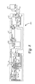
- FIG. 1 is a partially exploded view of the preferred embodiment of the probe of the invention used in conjunction with a needle assembly and a biopsy delivery system.
- FIG. 2 is a perspective view of the probe of FIG. 1 .
- FIG. 3 is a perspective view of the probe of FIG. 1 with a first elongate portion of the housing shown transparent.
- FIG. 4 is a perspective view of the probe of FIG. 1 with a second elongate portion of the housing shown transparent.
- FIG. 5 is an enlarged view of the connectors, sled, and transducer of FIGS. 3 and 4 .
- FIG. 6A is an enlarged view of the platform assembly, movable member, connectors, transducer, and sled of FIGS. 3 and 4 without the guide section of the second connector.
- FIG. 6B is an enlarged alternate view of the platform assembly, movable member, connectors, transducer, and sled of FIG. 6A .
- FIG. 7 is a perspective view of the probe of FIG. 1 with a third elongate portion of the housing shown transparent.
- FIG. 8 is a block diagram of the single motor scanning probe and circuit board of the integrated electronics of the probe assembly of the invention.
- FIG. 9 is a broken side view of the biopsy needle of the invention.
- FIG. 10A is a side view of the tissue piercing distal end of the biopsy needle of FIG. 9 .
- FIG. 10B is a longitudinal view of the cross section of the sampling section of the biopsy needle of FIG. 9 .
- FIG. 10C is a longitudinal view of the cross section of the bending section of the biopsy needle of FIG. 9 .
- FIG. 10D is a longitudinal view of the cross section of the body portion of the biopsy needle of FIG. 9 .
- FIG. 11 is a side view of the cannula of the invention.
- FIG. 12A is a top view of the guide assembly of the invention.
- FIG. 12B is a side view of the guide assembly of FIG. 12A .
- FIG. 13 is a schematic view of the biopsy needle, cannula, and guide assembly mounted on the first elongate portion of the probe of FIG. 1 and used to biopsy the prostate of a patient.
- FIG. 14A is a perspective view of an ultrasonic probe known in the art.
- FIG. 14B is a side partially sliced view of a drive assembly known in the art.
- FIG. 14C is a perspective view of a platform assembly and movable member known in the art.
- FIG. 14D is a cutaway view disclosing operative components of an ultrasonic probe known in the art.
- an improved transrectal ultrasonic probe 10 is shown in conjunction with a biopsy needle 110 , a cannula 112 for receiving and supporting the biopsy needle 110 , and a delivery system which includes a guide assembly 111 for guiding the biopsy needle 110 .
- the needle 110 and cannula 112 are preferably at least partially disposed within and coupled to a biopsy gun 107 .
- the biopsy needle 110 , cannula 112 , guide assembly 111 , and biopsy gun 107 are further discussed below with respect to the operation of these devices in conjunction with the improved probe 10 to capture biopsy tissue samples in a patient.
- the probe 10 has a housing 11 which includes a first elongate portion 12 , a second elongate portion 14 proximal of the first elongate portion, and a third elongate portion 16 proximal of the second elongate portion 14 .
- the first elongate portion 12 is substantially narrower (e.g., has a substantially smaller cross sectional area) than the second elongate portion 14 , and preferably has a circular cross section with an outside diameter of approximately 0.745 inches, preferably between 0.740 inches and 0.750 inches.
- the second elongate portion 14 preferably has a circular cross section with an outside diameter of approximately 1.06 inches, preferably between 0.75 inches and 1.4 inches.
- the third elongate portion 16 preferably has an outer body width of approximately 1.62 inches, preferably between 1.4 inches and 2.0 inches.
- the probe 10 also includes a distal end 13 which is preferably spherically shaped with a decreasing cross sectional area in the distal direction to assist with insertion of the probe 10 into a patient.
- the first elongate portion 12 is inserted into the rectum of the patient with the larger second elongate portion 14 remaining outside of the rectum of the patient.
- the first elongate portion 12 of the housing 11 houses an ultrasonic transducer 18 which is capable of emitting acoustic energy through the first elongate portion 12 and surrounding body cavity and tissue, and detecting acoustic backscatter signals.
- the transducer 18 is preferably mounted on a sled 20 which is rigidly coupled to a first connector 22 and slidably coupled to a guide portion 32 of a second connector 24 via a slot 26 defined by the bottom portion of the sled 20 .
- the transducer 18 is longitudinally translatable through the first elongate portion 12 , preferably parallel to a central axis 30 extending through the first elongate portion 12 .
- the first connector 22 translates longitudinally through the first elongate portion 12 , and functions to push and pull the transducer 18 distally and proximally along the guide portion 32 of the second connector 24 .
- a coiled coax 21 which carries transducer signal data is preferably wrapped around the first connector 22 as shown.
- the second connector 24 includes both the guide portion 32 and a support brace 34 .
- the guide portion 32 is preferably made from metal or steel and is rigidly attached to the distal end 13 of the probe 10 .
- the guide portion 32 preferably extends parallel to the central axis 30 .
- the support brace 34 defines a slot 36 ( FIGS. 5 , 6 ) for receiving a proximal section of the guide portion 32 and functions to support the guide portion 32 .
- the support brace 34 is made of a plastic material that allows it to deflect to prevent binding thereof when the first elongate portion 12 of the probe 10 is bent.
- the second connector 24 thus provides a guided pathway for directing longitudinal translation of the sled 20 as well as the transducer 18 .
- the second connector 24 minimizes unwanted movement of the sled 20 and transducer 18 .
- the second connector 24 rigidly maintains the radial position of the sled 20 and transducer 18 relative to the first elongate portion 12 of the housing 11 and provides support to the sled 20 and transducer 18 .
- the first and second connectors 22 , 24 extend between the first and second elongate portions 12 , 14 of the housing 11 , and respectively attach to a movable member and a platform assembly within the second elongate portion 14 as further discussed below with respect to FIGS. 4 and 6 .
- the second elongate portion 14 of the housing 11 houses a platform assembly 42 which is rotatable within and relative to the second elongate portion 14 and longitudinally fixed relative thereto.
- the platform assembly 42 supports a movable member 44 which translates relative to a frame 48 of the platform assembly 42 .
- the movable member 44 is both rotatable within and relative to the second elongate portion 14 , and translatable therethrough.
- the platform assembly 42 in addition to the frame 48 , includes a transmission system 46 .
- the transmission system 46 functions to drive reciprocating proximal and distal translation of the movable member 44 through the second elongate portion 14 , and preferably converts rotation of a proximally situated drive shaft (further discussed below) into the translation of the movable member.
- the transmission system 46 includes a vertical bevel gear 50 , a horizontal bevel gear 52 , a belt pulley 54 , a belt 56 , and an integral belt pin (not shown).
- the horizontal bevel gear 52 engages with the vertical bevel gear 50
- the belt 56 and belt pulley 54 rotate with the horizontal bevel gear 52 .
- the integral belt pin is fixed to the belt 56 , and is positioned in and slidable through a slot (not shown) on a bottom side of the movable member 44 . As the belt pulley 54 rotates, the pin moves with the belt 56 and pulls the movable member 44 along with it.
- the pin When the pin reaches and traverses one of the proximal (hidden) and distal 55 arced ends of the belt pulley 54 , it slides through the slot in the bottom of the movable member 44 and then pulls the movable member 44 in the opposite direction as it circles back with the belt 56 toward the other of the proximal and distal 55 arced ends of the belt pulley 54 .
- the frame 48 of the transmission system 46 (best seen in FIG. 6A ) includes at least one track 58 which supports the movable member 44 and preferably extends parallel to a linear axis 60 through the second elongate portion 14 .
- the at least one track 58 may include, for example, two parallel beams or rails 59 .
- the movable member 44 is preferably a sled which is slidably coupled to the track 58 of the frame 48 as shown.
- the frame 48 includes a neck 61 that interfaces to a bearing 62 .
- the bearing 62 includes an outer race 69 which is longitudinally and rotatably fixed relative to the second elongate portion 14 of the housing 11 , and an inner race 67 which is rotatable relative to the outer race 69 and second elongate portion 14 .
- the neck 61 includes a plate portion 53 which is preferably situated in an interference fit with the inner race 67 of the bearing 62 .
- the plate portion 53 defines a first hole 64 for slidably receiving the first connector 22 , and a second hole 66 for rigidly receiving the second connector 24 .
- the bearing 62 functions to provide support to the frame 48 and first and second connectors 22 , 24 , and to prevent radial movement thereof relative to the housing 11 .
- the plate portion 53 includes additional holes 63 , 65 for allowing the ultrasonic fluid to freely flow between the first and second elongate portions 12 , 14 .
- the proximal end of the second elongate portion 14 is sealed so that no fluid flows into the third elongate portion 16 .
- the first connector 22 extends through the hole 64 , preferably parallel to the linear axis 60 between the parallel rails 58 of the frame 48 , and is rigidly coupled to the movable member 44 at a proximal end 45 .
- the second connector 24 extends through the hole 66 , preferably parallel to the linear axis 60 , and is rigidly coupled to the neck 61 of the frame 48 .
- first connector 22 rigidly couples the transducer 18 in the first elongate portion 12 of the housing 11 to the movable member 44 in the second elongate portion 14 of the housing 11 , and thus that reciprocating proximal and distal longitudinal translation of the movable member 44 along the characteristic length L caused by the transmission system 46 causes reciprocating proximal and distal longitudinal translation of the transducer 18 within the first elongate portion 12 of the housing 11 along a length equivalent to the length L.
- the first connector 22 thus has a length which preferably exceeds the characteristic length L, and also which preferably exceeds the longitudinal length of the second elongate portion 12 such that when the movable member 44 is disposed in the proximal-most position in the frame 48 (e.g., FIGS. 4 & 6B ), the first connector 22 still extends through the entire second elongate portion 12 and into the first elongate portion.
- the second connector 24 also preferably has a length which exceeds the characteristic length L as well as the longitudinal length of the second elongate portion. The second connector 24 slidably couples the transducer 18 to the platform assembly 42 .
- rotation of the entire platform assembly 42 about the central axis thereof 57 in either a clockwise or counterclockwise direction relative to the second elongate portion 14 of the housing 11 drives rotation of the movable member 44 and first and second elongate members 22 , 24 , which causes the transducer 18 to rotate in the same direction within the first elongate portion 12 about the central axis 57 .
- first and second elongate portions 12 , 14 of the housing 11 are fluidly coupled with each other and filled with a ultrasonic coupling medium (e.g., ultrasonic transmission oil) which flows freely between the first and second elongate portions 12 , 14 .
- a ultrasonic coupling medium e.g., ultrasonic transmission oil
- the third elongate portion 16 of the housing 11 can function as a handle for manual operation of the probe 10 , or can be grasped by a stand for automated operation thereof.
- the third elongate portion 16 houses a motor, clutch, brake, and control circuitry for driving the rotation of two coaxial drive shafts coupled to the frame 48 and the transmission system 46 of the platform assembly 42 in order to selectively rotate and translate the transducer 18 as further discussed below.
- the third elongate portion 16 preferably houses a single motor 68 which rotatably drives an inner drive shaft 70 .
- the inner drive shaft 70 extends from the motor 68 through the third elongate portion 16 of the housing 11 to the proximal end of the second elongate portion 14 where it is rotatably coupled to the vertical bevel gear 50 of the transmission system 46 ( FIGS. 6A , 6 B).
- the inner shaft 70 thus linearly and reciprocally drives the movable member 44 .
- An electrically controlled clutch 72 is mounted about the inner shaft 70 within the third elongate portion 16 , and an outer shaft 74 extends from the clutch 72 .
- the outer shaft 74 is hollow and surrounds the inner shaft 70 , which extends through it.
- the outer shaft 74 extends from the clutch 72 through the third elongate portion 16 of the housing 11 to the proximal end of the second elongate portion 14 where it is rotatably fixed to the frame 48 of the platform assembly 42 .
- An electrically controlled brake 76 is mounted about the outer shaft 74 within the third elongate portion 16 forward of the clutch 72 , and is operable to prevent rotation of the outer shaft 74
- the clutch 72 and brake 76 operate under control of electrical signals supplied by a motor control processor unit (MCPU).
- the MCPU can issue a signal which engages or disengages the clutch 72 and brake 76 .
- the clutch 72 When the clutch 72 is engaged, it locks (rotatably fixes) the inner and outer shafts 70 , 74 to each other such that the outer shaft 74 is rotated by the rotation of the inner shaft 70 .
- the outer shaft 74 is rotatably fixed to the frame 48 of the platform assembly 42
- rotation of the inner shaft 70 by the motor 68 drives rotation of the outer shaft 74 and the entire platform assembly 42 about its central axis 30 without operating the transmission system 46 .
- the clutch 72 When the clutch 72 is unengaged and the brake is engaged, rotation of the inner shaft 70 by the motor 68 operates the transmission system 46 as the inner shaft 70 rotates relative to the outer shaft 74 .
- the probe 10 preferably includes an outer shaft encoder (not shown) and an inner shaft encoder 71 for monitoring the longitudinal and rotational position of the transducer 18 .
- the encoders each include a wheel which rotates with a respective shaft, and a sensor which monitors the rotational position of the wheel as known in the art.
- the encoders send signals to the MCPU 73 indicative of the longitudinally and rotational position of the transducer 18 . Rotational and positional feedback allow for accurate positioning and rotation of the probe 10 by the physician.
- the clutch 72 and brake 76 are controlled by a motion control processing unit (MCPU) 73 .
- the MCPU 73 is operatively connected to a control box or PC.
- the MCPU 73 engages and disengages the clutch 72 and brake 76 to allow for rotational and reciprocal motion of the transducer 18 in the second elongate portion 14 .
- the clutch 72 is released and the brake 76 is applied.
- the clutch 72 is engaged and the brake 76 is released.
- the MCPU 73 will signal the clutch 72 and brake 76 to engage or disengage depending on the commands initiated by the physician.
- the circuitry and electronics of the probe 10 preferably include a controller 83 , a pulser/receiver 205 , a digitizer 87 , and a high speed data interface 89 .
- the controller 83 receives commands from an external data processing system (e.g., a PC computer) 91 having a touch screen display 93 or other control dials and buttons via the data interface 89 . These commands are used to configure both the pulser/receiver 85 and the probe 10 .
- An acoustic pulse is generated in the pulser/receiver 85 and sent to the scanning probe 10 over a coaxial cable.
- Backscattered ultrasound data from the probe transducer 18 is processed by the receiver 85 .
- the data is then digitized by the digitizer 87 and sent to a memory buffer in the controller 83 .
- the data is then sent to the PC 91 for image formation on the touch screen display 93 via the data interface 89 .
- the controller 83 engages the clutch 72 and disengages the brake 76 to allow for rotational motion of the transducer 18 in the first elongate portion 12 while the transducer 18 remains longitudinally fixed relative thereto (the transmission 46 is inoperable because the inner shaft 70 is rotatably fixed to the outer shaft 74 ).
- the controller 83 disengages the clutch 72 and engages the brake 76 to allow for reciprocating translation of the transducer 18 in the first elongate portion 12 while precluding rotation of it relative thereto (the inner shaft 70 is disengaged from the outer shaft 74 and drives the transmission 46 , and the outer shaft 74 is prevented from rotating, which prevents rotation of the platform assembly 42 which is rotatably fixed to the outer shaft 74 , and hence the transducer 18 , which is rotatably fixed to the platform assembly 42 ).
- the controller 83 receives information on the position of the transducer 18 from a position tracker (not shown), which is connected to the probe's rotational axis encoder and linear axis encoder.
- a position tracker not shown
- Various embodiments of the electronics driving operation of the probe 10 can be utilized, including all of those disclosed in U.S. patent application Ser. No. 11/475,674 which has been incorporated herein by reference.
- the improved probe 10 allows for controlled translational and rotational movement of the ultrasonic transducer 18 inside and across the substantially narrow distal scanning portion 12 of the probe's housing 11 .
- the narrow distal scanning portion 12 facilitates positioning and orienting of the probe 10 at different angles within the patient about the prostate, and imaging and biopsying the prostate as discussed below.
- two connectors are preferred for connecting to the transducer 18 to facilitate translation and rotation thereof, it will be appreciated that a single connector may be utilized which rigidly couples the transducer 18 to the movable member 44 , provided that such single connector is sufficiently rigid to firmly maintain the radial position of the transducer 18 relative to the first elongate portion 12 of the housing 11 (e.g. provided the single connector does not bend).
- a single connector should not be directly fixed to the frame 48 of the platform assembly 42 as it would need to translate with the movable member 44 relative to the frame 48 .
- the first connector 22 is sufficient to provide the aforementioned controlled movement to the transducer 18 without guide 32 and support 34 of the second connector 24 provided that the first connector 22 is fixed at both ends to the transducer 18 and movable member 44 , does not bend, and will not bend over repeated use of the probe 10 .
- the improved transrectal ultrasonic probe 10 may be used in conjunction with various biopsy needles and delivery systems known in the art, including, for example, those disclosed in U.S. patent application Ser. Nos. 11/895,228 and 11/475,674, which are herein incorporated by reference in their entireties.
- the needle 110 includes a proximal end 114 , a tissue piercing distal end 116 , a sampling section 118 proximal of the tissue piercing distal end 116 and having a flat top surface 124 , rounded bottom surface 126 , and ground down rounded edges 128 , 130 on opposite sides of the top surface 124 , a bending section 120 proximal of the sampling section 118 and preferably having a circular cross section, and a body portion 122 proximal of the bending section 120 .
- the sampling section 118 , bending section 120 , and body portion 122 of the needle 110 are all preferably solidly and integrally formed with varying degrees of flexibility.
- the bending section 120 is preferably the most flexible portion of the needle 110 .
- the improved probe 10 may be used in conjunction with the needle 110 , cannula 112 , and guide assembly 111 in accordance with the biopsy procedure described in U.S. patent application Ser. No. 12/834,357.
- various other methodologies, embodiments, and additional equipment may be utilized with the improved probe 10 to procure a biopsy sample, including, for example, the methodologies, embodiments, and additional equipment described in U.S. patent application Ser. No. 11/895,228.
- the improved ultrasonic probe 10 and needle assembly (e.g. needle 110 and cannula 112 ) are used with a delivery system which includes the guide assembly 111 and a biopsy gun 107 to procure a tissue sample from the prostate 184 of a patient.
- the needle 110 and cannula 112 are preferably at least partially disposed within and coupled to the biopsy gun 107 .
- the narrow elongate distal scanning portion 12 of the improved probe 10 is inserted into the rectum of the patient adjacent the prostate 184 as shown in FIG. 14 .
- the substantially small scanning portion 12 of the housing 11 facilitates insertion into the rectum, and positioning and orienting the probe 10 therein.
- Transrectal probes commonly used in the art cause significant discomfort to the patient, and the inventors have found that the transrectal probe of application Ser. Nos. 11/895,228 and 11/475,674 also cause discomfort to patients.
- the substantially narrow distal scanning section 12 of the new improved probe 10 reduces this discomfort.
- the guide assembly 111 is preferably attached to a guide/index collar 189 ( FIG. 1 ) of the probe 10 .
- the guide/index collar 189 controls radial and axial movement of the guide assembly 111 on the probe 10 , and preferably orients the guide assembly 111 such that it straddles the probe 110 adjacent an imaging window 123 in the probe 10 , and is sloped slightly downward at a ten degree angle.
- the guide assembly 111 may be fixed to the probe 110 and/or oriented horizontally relative thereto. Ultrasonic images of the prostate 184 are received through the imaging window 123 , unobstructed by the guide assembly 111 .
- the respective distal ends 116 , 156 of the needle 110 and cannula 112 are advanced together through the inlet 75 of the guide assembly 111 and are guided to a fixed orientation and direction at the outlet 181 of the guide assembly 111 to place the needle 110 and cannula 112 in a bent configuration within the patient adjacent the prostate.
- the biopsy gun 107 is fired to advance the needle 110 from the bent configuration into the prostate 184 of the patient.
- the sampling portion 118 of the needle 110 rapidly advances out of the cannula 112 into the prostate over a stroke length which is preferably approximately equal to the length of the sampling section 118 .
- a second firing of the biopsy gun 107 causes the cannula 112 to fire and advance over the exposed sampling section 118 of the needle 110 in the prostate 184 , capturing sample tissue therein between the cannula 112 and the needle 110 .
- the needle 110 and cannula 112 are then withdrawn from the patient with the tissue sample captured within the cannula 12 , and the process is repeated as needed with the improved probe 10 remaining in the patient. It will be appreciated that the narrower distal elongate portion 12 of the housing 11 of the new probe 10 allows for easier manipulation inside of the patient to different positions and orientations.
- the improved ultrasonic probe may also be used to provide guidance during transperineal procedures including brachytherapy, chryotherapy or other transperineal saturation biopsies in which the needle is inserted through a grid through the perineum and transrectal images from the probe are used for guidance.
- Brachytherapy is a minimally invasive treatment that administers radioactive seeds (the size of a grain of rice) directly into the prostate, which allows the ability to use higher doses in the seeds without damaging any surrounding healthy tissue.
- the radioactive seeds are placed into thin needles and directed into the prostate through the perineum.
- the seeds release low dose radiation for several weeks or months, killing the cancer cells.
- Cryotherapy uses argon gas to freeze and helium gas to thaw, a process which destroys cancer cells in the prostate.
- a warming catheter is inserted through the urethra to protect it during the freezing process of the prostate. The cancer cells in the prostate are destroyed as they thaw.
- the probe may also be used for guidance during laparascopic and non-laparoscopic surgeries involving other cavities such as the abdominal cavity (e.g., surgeries involving the small intestine, large intestine, stomach, spleen, liver, pancreas, kidneys, and adrenal glands), the thoracic cavity, and the pelvic cavity, or during surgeries involving other tissue or joints in the body.
- abdominal cavity e.g., surgeries involving the small intestine, large intestine, stomach, spleen, liver, pancreas, kidneys, and adrenal glands
- thoracic cavity e.g., surgeries involving the small intestine, large intestine, stomach, spleen, liver, pancreas, kidneys, and adrenal glands
- the needle, cannula, and improved probe have been disclosed for biopsying the prostate of a patient, it will be recognized that that the needle, cannula, and improved probe can be used for biopsying tissue of other organs or other parts of the body and that the improved probe may be inserted through other cavities in the body and utilized for guiding other procedures such as brachytherapy, chryotherapy and saturation biopsies. It will therefore be appreciated by those skilled in the art that yet other modifications could be made to the provided invention without deviating from its spirit and scope as claimed.
Abstract
Description
Claims (22)
Priority Applications (2)
| Application Number | Priority Date | Filing Date | Title |
|---|---|---|---|
| US12/834,384 US8758256B2 (en) | 2010-07-12 | 2010-07-12 | Apparatus for brachytherapy that uses a scanning probe for treatment of malignant tissue |
| PCT/US2011/043506 WO2012009251A1 (en) | 2010-07-12 | 2011-07-11 | Scanning probe |
Applications Claiming Priority (1)
| Application Number | Priority Date | Filing Date | Title |
|---|---|---|---|
| US12/834,384 US8758256B2 (en) | 2010-07-12 | 2010-07-12 | Apparatus for brachytherapy that uses a scanning probe for treatment of malignant tissue |
Publications (2)
| Publication Number | Publication Date |
|---|---|
| US20120010512A1 US20120010512A1 (en) | 2012-01-12 |
| US8758256B2 true US8758256B2 (en) | 2014-06-24 |
Family
ID=45439083
Family Applications (1)
| Application Number | Title | Priority Date | Filing Date |
|---|---|---|---|
| US12/834,384 Active 2031-11-27 US8758256B2 (en) | 2010-07-12 | 2010-07-12 | Apparatus for brachytherapy that uses a scanning probe for treatment of malignant tissue |
Country Status (2)
| Country | Link |
|---|---|
| US (1) | US8758256B2 (en) |
| WO (1) | WO2012009251A1 (en) |
Cited By (4)
| Publication number | Priority date | Publication date | Assignee | Title |
|---|---|---|---|---|
| US20230076502A1 (en) * | 2021-08-24 | 2023-03-09 | Hyperion Surgical, Inc. | Robotic systems, devices, and methods for vascular access |
| US11678944B1 (en) | 2022-08-23 | 2023-06-20 | Hyperion Surgical, Inc. | Manipulators and cartridges for robotic-assisted vascular access |
| US11723686B2 (en) | 2017-05-02 | 2023-08-15 | Koninklijke Philips N.V. | Transperineal stepper including rotatable transducer probe and shaft with internal cable |
| US11903663B2 (en) | 2021-08-24 | 2024-02-20 | Hyperion Surgical, Inc. | Robotic systems, devices, and methods for vascular access |
Families Citing this family (7)
| Publication number | Priority date | Publication date | Assignee | Title |
|---|---|---|---|---|
| WO2013040017A1 (en) | 2011-09-16 | 2013-03-21 | Hologic Inc. | Breast biopsy lateral arm system |
| US11284869B2 (en) | 2011-09-16 | 2022-03-29 | Hologic, Inc. | Breast biopsy lateral arm system |
| KR102136174B1 (en) * | 2013-08-13 | 2020-07-21 | 삼성메디슨 주식회사 | Ultrasonic diagnostic apparatus |
| US10849650B2 (en) * | 2015-07-07 | 2020-12-01 | Eigen Health Services, Llc | Transperineal needle guidance |
| CN107049370B (en) * | 2017-05-26 | 2019-08-06 | 北京龙慧珩医疗科技发展有限公司 | A kind of prostate biopsy external member |
| CN107049371B (en) * | 2017-05-26 | 2019-08-13 | 北京龙慧珩医疗科技发展有限公司 | A kind of prostate biopsy art biopsy removing method and device |
| RU2740113C1 (en) * | 2019-12-05 | 2021-01-11 | Михаил Юрьевич Гвоздев | Method for ultrasonic examination of cystic para-urethral formations in females |
Citations (93)
| Publication number | Priority date | Publication date | Assignee | Title |
|---|---|---|---|---|
| US3946613A (en) * | 1974-03-07 | 1976-03-30 | Lmc Data, Inc. | Electronic thermometer and probe |
| US4166389A (en) * | 1978-05-03 | 1979-09-04 | Arbrook, Inc. | Electronic thermometer probe assembly |
| US4374525A (en) | 1980-04-28 | 1983-02-22 | Olympus Optical Co., Ltd. | Ultrasonic diagnostic apparatus for endoscope |
| EP0142862A2 (en) | 1983-11-21 | 1985-05-29 | Matsushita Electric Industrial Co., Ltd. | Ultrasonic probe having a liquid-containing housing formed of polymethylpentene resin |
| US4756313A (en) | 1986-11-05 | 1988-07-12 | Advanced Diagnostic Medical Systems, Inc. | Ultrasonic probe |
| US4757818A (en) | 1986-03-03 | 1988-07-19 | Angelsen Bjorn A J | Ultrasonic transducer probe with linear motion drive mechanism |
| US4771774A (en) * | 1986-02-28 | 1988-09-20 | Devices For Vascular Intervention, Inc. | Motor drive unit |
| US4802458A (en) | 1984-03-09 | 1989-02-07 | Ethicon, Inc. | Dual function ultrasonic transducer probes |
| US4819650A (en) | 1987-10-30 | 1989-04-11 | Wayne State University | Biplane probe including centerline highlighting |
| US4841979A (en) | 1988-01-25 | 1989-06-27 | Capistrano Labs, Inc. | Ultrasonic prostate probe assembly |
| US4917096A (en) | 1987-11-25 | 1990-04-17 | Laboratory Equipment, Corp. | Portable ultrasonic probe |
| US4944308A (en) | 1987-11-19 | 1990-07-31 | C. R. Bard, Inc. | Tissue sampling device |
| US5048529A (en) | 1988-09-01 | 1991-09-17 | Elscint Ltd. | Ultrasonic transducer probe |
| US5050610A (en) | 1990-11-14 | 1991-09-24 | Advanced Technology Laboratories, Inc. | Transesophageal ultrasonic scanhead |
| US5054491A (en) | 1988-10-17 | 1991-10-08 | Olympus Optical Co., Ltd. | Ultrasonic endoscope apparatus |
| EP0453014A1 (en) | 1990-04-20 | 1991-10-23 | Technische Universiteit Delft | Scanner for ultrasonic scanning of surfaces |
| US5070879A (en) | 1989-11-30 | 1991-12-10 | Acoustic Imaging Technologies Corp. | Ultrasound imaging method and apparatus |
| US5090414A (en) | 1988-08-22 | 1992-02-25 | Kabushiki Kaisha Toshiba | Intracavitary ultrasound probe |
| US5105819A (en) | 1988-09-01 | 1992-04-21 | Kon-Tron Elektronik AG | Ultrasound endoscope device |
| US5107844A (en) * | 1989-04-06 | 1992-04-28 | Olympus Optical Co., Ltd. | Ultrasonic observing apparatus |
| EP0504480A2 (en) | 1991-03-20 | 1992-09-23 | Olympus Optical Co., Ltd | Ultrasonic diagnostic apparatus using a linear and angular scanning probe |
| US5152294A (en) | 1989-12-14 | 1992-10-06 | Aloka Co., Ltd. | Three-dimensional ultrasonic scanner |
| US5159931A (en) | 1988-11-25 | 1992-11-03 | Riccardo Pini | Apparatus for obtaining a three-dimensional reconstruction of anatomic structures through the acquisition of echographic images |
| US5170793A (en) * | 1990-02-07 | 1992-12-15 | Kabushiki Kaisha Toshiba | Ultrasonic probe |
| US5181514A (en) | 1991-05-21 | 1993-01-26 | Hewlett-Packard Company | Transducer positioning system |
| WO1993016641A1 (en) | 1992-02-21 | 1993-09-02 | Diasonics, Inc. | Ultrasound intracavity system for imaging therapy planning and treatment of focal disease |
| US5331962A (en) | 1993-04-16 | 1994-07-26 | Cornell Research Foundation Inc. | Ultrasound system for corneal biometry |
| US5361768A (en) | 1992-06-30 | 1994-11-08 | Cardiovascular Imaging Systems, Inc. | Automated longitudinal position translator for ultrasonic imaging probes, and methods of using same |
| US5368045A (en) | 1989-07-18 | 1994-11-29 | Boston Scientific Corporation | Biopsy needle instrument |
| US5383460A (en) * | 1992-10-05 | 1995-01-24 | Cardiovascular Imaging Systems, Inc. | Method and apparatus for ultrasound imaging and atherectomy |
| US5394878A (en) | 1993-07-13 | 1995-03-07 | Frazin; Leon J. | Method for two dimensional real time color doppler ultrasound imaging of bodily structures through the gastro intestinal wall |
| US5398690A (en) | 1994-08-03 | 1995-03-21 | Batten; Bobby G. | Slaved biopsy device, analysis apparatus, and process |
| US5429136A (en) * | 1993-04-21 | 1995-07-04 | Devices For Vascular Intervention, Inc. | Imaging atherectomy apparatus |
| US5456258A (en) | 1993-12-20 | 1995-10-10 | Fuji Photo Optical Co., Ltd. | Catheter type ultrasound probe |
| US5460179A (en) | 1992-05-27 | 1995-10-24 | Aloka Co., Ltd. | Ultrasonic transducer assembly and method of scanning |
| US5474072A (en) | 1993-10-29 | 1995-12-12 | Neovision Corporation | Methods and apparatus for performing sonomammography |
| US5497776A (en) | 1993-08-05 | 1996-03-12 | Olympus Optical Co., Ltd. | Ultrasonic image diagnosing apparatus for displaying three-dimensional image |
| US5526822A (en) * | 1994-03-24 | 1996-06-18 | Biopsys Medical, Inc. | Method and apparatus for automated biopsy and collection of soft tissue |
| US5611343A (en) | 1995-04-05 | 1997-03-18 | Loral Aerospace Corp. | High resolution three-dimensional ultrasound imaging |
| US5634466A (en) | 1993-11-19 | 1997-06-03 | Advanced Technology Laboratories, Inc. | Ultrasonic transesophageal probe with detachable transducer tip |
| US5660185A (en) | 1995-04-13 | 1997-08-26 | Neovision Corporation | Image-guided biopsy apparatus with enhanced imaging and methods |
| US5671748A (en) | 1995-04-28 | 1997-09-30 | Fuji Photo Optical Co., Ltd. | Ultrasound endoscope having ultrasound probe in combination with endoscopic observation system |
| US5769079A (en) | 1996-10-22 | 1998-06-23 | Acuson Corporation | Method and apparatus for determining quantitative measures of flow parameters |
| US5810007A (en) | 1995-07-26 | 1998-09-22 | Associates Of The Joint Center For Radiation Therapy, Inc. | Ultrasound localization and image fusion for the treatment of prostate cancer |
| US5842473A (en) | 1993-11-29 | 1998-12-01 | Life Imaging Systems | Three-dimensional imaging system |
| US5873828A (en) | 1994-02-18 | 1999-02-23 | Olympus Optical Co., Ltd. | Ultrasonic diagnosis and treatment system |
| US5875778A (en) | 1989-04-26 | 1999-03-02 | B.V. Optische Industrie `De Oude Delft` | Electrode for stimulating and/or detecting muscle activity of a patient accessible through a body orifice |
| US5931788A (en) | 1997-12-05 | 1999-08-03 | Keen; Richard R. | Method and apparatus for imaging internal organs and vascular structures through the gastrointestinal wall |
| US5951489A (en) | 1997-01-09 | 1999-09-14 | Allegiance Healthcare Corporation | Biopsy surgical appliance |
| US6004271A (en) | 1998-05-07 | 1999-12-21 | Boston Scientific Corporation | Combined motor drive and automated longitudinal position translator for ultrasonic imaging system |
| US6036649A (en) | 1997-06-17 | 2000-03-14 | Kabushiki Kaisha Toshiba | Ultrasound probe |
| US6102867A (en) | 1997-02-11 | 2000-08-15 | Tetrad Corporation | Sheath and methods of ultrasonic guidance of biopsy and catheter insertion |
| US6149598A (en) | 1998-03-31 | 2000-11-21 | Fuji Photo Optical Co., Ltd. | Ultrasound endoscope |
| US6165136A (en) | 1998-12-23 | 2000-12-26 | Scimed Life Systems, Inc. | Semi-automatic biopsy device and related method of use |
| US6171249B1 (en) | 1997-10-14 | 2001-01-09 | Circon Corporation | Ultrasound guided therapeutic and diagnostic device |
| WO2001008561A1 (en) | 1999-07-30 | 2001-02-08 | Boston Scientific Limited | Rotational and translational drive coupling for catheter assembly |
| US6200269B1 (en) | 1998-05-28 | 2001-03-13 | Diasonics, Ultrasound, Inc. | Forward-scanning ultrasound catheter probe |
| US6238336B1 (en) | 1998-03-04 | 2001-05-29 | Asahi Kogaku Kogyo Kabushiki Kaisha | Ultrasonic endoscope including radial scanning and linear scanning ultrasonic transducers |
| US6261234B1 (en) | 1998-05-07 | 2001-07-17 | Diasonics Ultrasound, Inc. | Method and apparatus for ultrasound imaging with biplane instrument guidance |
| US6261243B1 (en) | 1998-10-13 | 2001-07-17 | Emx, Inc. | Biopsy marker assembly and method of use |
| US6315724B1 (en) | 1999-10-19 | 2001-11-13 | Biomedicom Ltd | 3-dimensional ultrasonic imaging |
| US20020002349A1 (en) | 1996-10-11 | 2002-01-03 | Transvascular, Inc. | Systems and methods for delivering drugs to selected locations within the body |
| US6390973B1 (en) | 1998-06-25 | 2002-05-21 | Asahi Kogaku Kogyo Kabushiki Kaisha | Endoscope for ultrasonic examination and surgical treatment associated thereto |
| US6409666B1 (en) | 1999-04-15 | 2002-06-25 | Asahi Kogaku Kogyo Kabushiki Kaisha | Tip end of ultrasonic endoscope |
| US6425867B1 (en) * | 1998-09-18 | 2002-07-30 | University Of Washington | Noise-free real time ultrasonic imaging of a treatment site undergoing high intensity focused ultrasound therapy |
| US20020111634A1 (en) | 2000-08-30 | 2002-08-15 | Johns Hopkins University | Controllable motorized device for percutaneous needle placement in soft tissue target and methods and systems related thereto |
| US6447477B2 (en) | 1996-02-09 | 2002-09-10 | Emx, Inc. | Surgical and pharmaceutical site access guide and methods |
| US6485411B1 (en) | 2000-04-12 | 2002-11-26 | Circon Corporation | Endoscope shaft with superelastic alloy spiral frame and braid |
| US20030073907A1 (en) * | 2001-10-16 | 2003-04-17 | Taylor James D. | Scanning probe |
| US20030078502A1 (en) | 2001-10-23 | 2003-04-24 | Olympus Optical Co., Ltd. | Device for examining a subject capable of marking a boundary range for insertion/retraction of an insertion/retraction member that is inserted in and retracted from the subject |
| US6565588B1 (en) | 2000-04-05 | 2003-05-20 | Pathway Medical Technologies, Inc. | Intralumenal material removal using an expandable cutting device |
| US20030120154A1 (en) | 2001-11-28 | 2003-06-26 | Frank Sauer | Method and apparatus for ultrasound guidance of needle biopsies |
| US20030135119A1 (en) | 2001-12-31 | 2003-07-17 | Medison Co., Ltd. | Method and apparatus for enabling a biopsy needle to be observed |
| US20030158475A1 (en) * | 2000-03-30 | 2003-08-21 | Johnson Vicki Young | Intravaginal radiofrequency imaging device |
| WO2003088833A1 (en) | 2002-04-22 | 2003-10-30 | The Johns Hopkins University | Apparatus for insertion of a medical device during a medical imaging process |
| US20040030250A1 (en) | 2000-06-22 | 2004-02-12 | Duncan Stewart | Injection system for gene delivery |
| US6712783B1 (en) | 1992-11-13 | 2004-03-30 | Cardiovascular Imaging, Inc. | Catheter system having a balloon angioplasty device disposed over a work element lumen |
| US20040133111A1 (en) | 2003-01-03 | 2004-07-08 | Civco Medical Instruments Inc. | Shallow angle needle guide apparatus and method |
| US6884219B1 (en) | 2002-10-17 | 2005-04-26 | Rick L. Pruter | Method and disposable apparatus for guiding needles with an endocavity medical imaging device |
| US20050119570A1 (en) | 2003-12-01 | 2005-06-02 | Stephen Lewis | Ultrasonic image and visualization aid |
| US20050159676A1 (en) | 2003-08-13 | 2005-07-21 | Taylor James D. | Targeted biopsy delivery system |
| US20050203413A1 (en) | 2003-08-07 | 2005-09-15 | Gabor Fichtinger | Transcavital needle insertion device |
| US7171255B2 (en) | 1995-07-26 | 2007-01-30 | Computerized Medical Systems, Inc. | Virtual reality 3D visualization for surgical procedures |
| US20070038126A1 (en) * | 2005-06-23 | 2007-02-15 | Pyle Jason L | System and method for monitoring of end organ oxygenation by measurement of in vivo cellular energy status |
| US20070123797A1 (en) | 2004-06-01 | 2007-05-31 | William Krause | Automated biopsy and delivery device |
| US20080161687A1 (en) | 2006-12-29 | 2008-07-03 | Suri Jasjit S | Repeat biopsy system |
| US20080159606A1 (en) | 2006-10-30 | 2008-07-03 | Suri Jasit S | Object Recognition System for Medical Imaging |
| US20080269588A1 (en) | 2007-04-24 | 2008-10-30 | Medtronic, Inc. | Intraoperative Image Registration |
| US20090048515A1 (en) | 2007-08-14 | 2009-02-19 | Suri Jasjit S | Biopsy planning system |
| US20090270737A1 (en) * | 2008-02-28 | 2009-10-29 | Boston Scientific Scimed, Inc | Imaging catheter |
| US20090318832A1 (en) | 2008-06-18 | 2009-12-24 | Andreyko Michael J | Biopsy Devices with Universal Probe |
| US20100036293A1 (en) | 2008-08-05 | 2010-02-11 | Scott Isola | HIFU treatment probe |
| US20110201976A1 (en) * | 2005-06-01 | 2011-08-18 | Focus Surgery, Inc. | Laparoscopic hifu probe |
-
2010
- 2010-07-12 US US12/834,384 patent/US8758256B2/en active Active
-
2011
- 2011-07-11 WO PCT/US2011/043506 patent/WO2012009251A1/en active Application Filing
Patent Citations (102)
| Publication number | Priority date | Publication date | Assignee | Title |
|---|---|---|---|---|
| US3946613A (en) * | 1974-03-07 | 1976-03-30 | Lmc Data, Inc. | Electronic thermometer and probe |
| US4166389A (en) * | 1978-05-03 | 1979-09-04 | Arbrook, Inc. | Electronic thermometer probe assembly |
| US4374525A (en) | 1980-04-28 | 1983-02-22 | Olympus Optical Co., Ltd. | Ultrasonic diagnostic apparatus for endoscope |
| EP0142862A2 (en) | 1983-11-21 | 1985-05-29 | Matsushita Electric Industrial Co., Ltd. | Ultrasonic probe having a liquid-containing housing formed of polymethylpentene resin |
| US4802458A (en) | 1984-03-09 | 1989-02-07 | Ethicon, Inc. | Dual function ultrasonic transducer probes |
| US4771774A (en) * | 1986-02-28 | 1988-09-20 | Devices For Vascular Intervention, Inc. | Motor drive unit |
| US4757818A (en) | 1986-03-03 | 1988-07-19 | Angelsen Bjorn A J | Ultrasonic transducer probe with linear motion drive mechanism |
| US4756313A (en) | 1986-11-05 | 1988-07-12 | Advanced Diagnostic Medical Systems, Inc. | Ultrasonic probe |
| US4819650A (en) | 1987-10-30 | 1989-04-11 | Wayne State University | Biplane probe including centerline highlighting |
| US4944308A (en) | 1987-11-19 | 1990-07-31 | C. R. Bard, Inc. | Tissue sampling device |
| US4917096A (en) | 1987-11-25 | 1990-04-17 | Laboratory Equipment, Corp. | Portable ultrasonic probe |
| US4841979A (en) | 1988-01-25 | 1989-06-27 | Capistrano Labs, Inc. | Ultrasonic prostate probe assembly |
| US5090414A (en) | 1988-08-22 | 1992-02-25 | Kabushiki Kaisha Toshiba | Intracavitary ultrasound probe |
| US5048529A (en) | 1988-09-01 | 1991-09-17 | Elscint Ltd. | Ultrasonic transducer probe |
| US5105819A (en) | 1988-09-01 | 1992-04-21 | Kon-Tron Elektronik AG | Ultrasound endoscope device |
| US5054491A (en) | 1988-10-17 | 1991-10-08 | Olympus Optical Co., Ltd. | Ultrasonic endoscope apparatus |
| US5159931A (en) | 1988-11-25 | 1992-11-03 | Riccardo Pini | Apparatus for obtaining a three-dimensional reconstruction of anatomic structures through the acquisition of echographic images |
| US5107844A (en) * | 1989-04-06 | 1992-04-28 | Olympus Optical Co., Ltd. | Ultrasonic observing apparatus |
| US5875778A (en) | 1989-04-26 | 1999-03-02 | B.V. Optische Industrie `De Oude Delft` | Electrode for stimulating and/or detecting muscle activity of a patient accessible through a body orifice |
| US5368045A (en) | 1989-07-18 | 1994-11-29 | Boston Scientific Corporation | Biopsy needle instrument |
| US5070879A (en) | 1989-11-30 | 1991-12-10 | Acoustic Imaging Technologies Corp. | Ultrasound imaging method and apparatus |
| US5152294A (en) | 1989-12-14 | 1992-10-06 | Aloka Co., Ltd. | Three-dimensional ultrasonic scanner |
| US5170793A (en) * | 1990-02-07 | 1992-12-15 | Kabushiki Kaisha Toshiba | Ultrasonic probe |
| EP0453014A1 (en) | 1990-04-20 | 1991-10-23 | Technische Universiteit Delft | Scanner for ultrasonic scanning of surfaces |
| US5050610A (en) | 1990-11-14 | 1991-09-24 | Advanced Technology Laboratories, Inc. | Transesophageal ultrasonic scanhead |
| EP0504480A2 (en) | 1991-03-20 | 1992-09-23 | Olympus Optical Co., Ltd | Ultrasonic diagnostic apparatus using a linear and angular scanning probe |
| US5181514A (en) | 1991-05-21 | 1993-01-26 | Hewlett-Packard Company | Transducer positioning system |
| WO1993016641A1 (en) | 1992-02-21 | 1993-09-02 | Diasonics, Inc. | Ultrasound intracavity system for imaging therapy planning and treatment of focal disease |
| US5762066A (en) | 1992-02-21 | 1998-06-09 | Ths International, Inc. | Multifaceted ultrasound transducer probe system and methods for its use |
| US5460179A (en) | 1992-05-27 | 1995-10-24 | Aloka Co., Ltd. | Ultrasonic transducer assembly and method of scanning |
| US5361768A (en) | 1992-06-30 | 1994-11-08 | Cardiovascular Imaging Systems, Inc. | Automated longitudinal position translator for ultrasonic imaging probes, and methods of using same |
| US5592942A (en) | 1992-06-30 | 1997-01-14 | Cardiovascular Imaging Systems, Inc. | Automated longitudinal position translator for ultrasonic imaging probes, and methods of using same |
| US5383460A (en) * | 1992-10-05 | 1995-01-24 | Cardiovascular Imaging Systems, Inc. | Method and apparatus for ultrasound imaging and atherectomy |
| US6712783B1 (en) | 1992-11-13 | 2004-03-30 | Cardiovascular Imaging, Inc. | Catheter system having a balloon angioplasty device disposed over a work element lumen |
| US5331962A (en) | 1993-04-16 | 1994-07-26 | Cornell Research Foundation Inc. | Ultrasound system for corneal biometry |
| US5429136A (en) * | 1993-04-21 | 1995-07-04 | Devices For Vascular Intervention, Inc. | Imaging atherectomy apparatus |
| US5394878A (en) | 1993-07-13 | 1995-03-07 | Frazin; Leon J. | Method for two dimensional real time color doppler ultrasound imaging of bodily structures through the gastro intestinal wall |
| US5497776A (en) | 1993-08-05 | 1996-03-12 | Olympus Optical Co., Ltd. | Ultrasonic image diagnosing apparatus for displaying three-dimensional image |
| US5474072A (en) | 1993-10-29 | 1995-12-12 | Neovision Corporation | Methods and apparatus for performing sonomammography |
| US5634466A (en) | 1993-11-19 | 1997-06-03 | Advanced Technology Laboratories, Inc. | Ultrasonic transesophageal probe with detachable transducer tip |
| US5964707A (en) | 1993-11-29 | 1999-10-12 | Life Imaging Systems Inc. | Three-dimensional imaging system |
| US5842473A (en) | 1993-11-29 | 1998-12-01 | Life Imaging Systems | Three-dimensional imaging system |
| US5456258A (en) | 1993-12-20 | 1995-10-10 | Fuji Photo Optical Co., Ltd. | Catheter type ultrasound probe |
| US5873828A (en) | 1994-02-18 | 1999-02-23 | Olympus Optical Co., Ltd. | Ultrasonic diagnosis and treatment system |
| US5526822A (en) * | 1994-03-24 | 1996-06-18 | Biopsys Medical, Inc. | Method and apparatus for automated biopsy and collection of soft tissue |
| US5398690A (en) | 1994-08-03 | 1995-03-21 | Batten; Bobby G. | Slaved biopsy device, analysis apparatus, and process |
| US5611343A (en) | 1995-04-05 | 1997-03-18 | Loral Aerospace Corp. | High resolution three-dimensional ultrasound imaging |
| US5660185A (en) | 1995-04-13 | 1997-08-26 | Neovision Corporation | Image-guided biopsy apparatus with enhanced imaging and methods |
| US5671748A (en) | 1995-04-28 | 1997-09-30 | Fuji Photo Optical Co., Ltd. | Ultrasound endoscope having ultrasound probe in combination with endoscopic observation system |
| US5810007A (en) | 1995-07-26 | 1998-09-22 | Associates Of The Joint Center For Radiation Therapy, Inc. | Ultrasound localization and image fusion for the treatment of prostate cancer |
| US7171255B2 (en) | 1995-07-26 | 2007-01-30 | Computerized Medical Systems, Inc. | Virtual reality 3D visualization for surgical procedures |
| US6447477B2 (en) | 1996-02-09 | 2002-09-10 | Emx, Inc. | Surgical and pharmaceutical site access guide and methods |
| US20020002349A1 (en) | 1996-10-11 | 2002-01-03 | Transvascular, Inc. | Systems and methods for delivering drugs to selected locations within the body |
| US6685648B2 (en) | 1996-10-11 | 2004-02-03 | Transvascular, Inc. | Systems and methods for delivering drugs to selected locations within the body |
| US5769079A (en) | 1996-10-22 | 1998-06-23 | Acuson Corporation | Method and apparatus for determining quantitative measures of flow parameters |
| US5951489A (en) | 1997-01-09 | 1999-09-14 | Allegiance Healthcare Corporation | Biopsy surgical appliance |
| US6102867A (en) | 1997-02-11 | 2000-08-15 | Tetrad Corporation | Sheath and methods of ultrasonic guidance of biopsy and catheter insertion |
| US6036649A (en) | 1997-06-17 | 2000-03-14 | Kabushiki Kaisha Toshiba | Ultrasound probe |
| US6171249B1 (en) | 1997-10-14 | 2001-01-09 | Circon Corporation | Ultrasound guided therapeutic and diagnostic device |
| US5931788A (en) | 1997-12-05 | 1999-08-03 | Keen; Richard R. | Method and apparatus for imaging internal organs and vascular structures through the gastrointestinal wall |
| US6238336B1 (en) | 1998-03-04 | 2001-05-29 | Asahi Kogaku Kogyo Kabushiki Kaisha | Ultrasonic endoscope including radial scanning and linear scanning ultrasonic transducers |
| US6149598A (en) | 1998-03-31 | 2000-11-21 | Fuji Photo Optical Co., Ltd. | Ultrasound endoscope |
| US6261234B1 (en) | 1998-05-07 | 2001-07-17 | Diasonics Ultrasound, Inc. | Method and apparatus for ultrasound imaging with biplane instrument guidance |
| US6004271A (en) | 1998-05-07 | 1999-12-21 | Boston Scientific Corporation | Combined motor drive and automated longitudinal position translator for ultrasonic imaging system |
| US6200269B1 (en) | 1998-05-28 | 2001-03-13 | Diasonics, Ultrasound, Inc. | Forward-scanning ultrasound catheter probe |
| US6390973B1 (en) | 1998-06-25 | 2002-05-21 | Asahi Kogaku Kogyo Kabushiki Kaisha | Endoscope for ultrasonic examination and surgical treatment associated thereto |
| US6425867B1 (en) * | 1998-09-18 | 2002-07-30 | University Of Washington | Noise-free real time ultrasonic imaging of a treatment site undergoing high intensity focused ultrasound therapy |
| US6261243B1 (en) | 1998-10-13 | 2001-07-17 | Emx, Inc. | Biopsy marker assembly and method of use |
| US6165136A (en) | 1998-12-23 | 2000-12-26 | Scimed Life Systems, Inc. | Semi-automatic biopsy device and related method of use |
| US6409666B1 (en) | 1999-04-15 | 2002-06-25 | Asahi Kogaku Kogyo Kabushiki Kaisha | Tip end of ultrasonic endoscope |
| WO2001008561A1 (en) | 1999-07-30 | 2001-02-08 | Boston Scientific Limited | Rotational and translational drive coupling for catheter assembly |
| US6315724B1 (en) | 1999-10-19 | 2001-11-13 | Biomedicom Ltd | 3-dimensional ultrasonic imaging |
| US20030158475A1 (en) * | 2000-03-30 | 2003-08-21 | Johnson Vicki Young | Intravaginal radiofrequency imaging device |
| US6565588B1 (en) | 2000-04-05 | 2003-05-20 | Pathway Medical Technologies, Inc. | Intralumenal material removal using an expandable cutting device |
| US6485411B1 (en) | 2000-04-12 | 2002-11-26 | Circon Corporation | Endoscope shaft with superelastic alloy spiral frame and braid |
| US20040030250A1 (en) | 2000-06-22 | 2004-02-12 | Duncan Stewart | Injection system for gene delivery |
| US20020111634A1 (en) | 2000-08-30 | 2002-08-15 | Johns Hopkins University | Controllable motorized device for percutaneous needle placement in soft tissue target and methods and systems related thereto |
| US6709397B2 (en) | 2001-10-16 | 2004-03-23 | Envisioneering, L.L.C. | Scanning probe |
| US20040204650A1 (en) | 2001-10-16 | 2004-10-14 | Taylor James D. | Scanning probe |
| US7066889B2 (en) | 2001-10-16 | 2006-06-27 | Envisioneering, Llc | Scanning probe |
| US20030073907A1 (en) * | 2001-10-16 | 2003-04-17 | Taylor James D. | Scanning probe |
| US20030078502A1 (en) | 2001-10-23 | 2003-04-24 | Olympus Optical Co., Ltd. | Device for examining a subject capable of marking a boundary range for insertion/retraction of an insertion/retraction member that is inserted in and retracted from the subject |
| US6689067B2 (en) | 2001-11-28 | 2004-02-10 | Siemens Corporate Research, Inc. | Method and apparatus for ultrasound guidance of needle biopsies |
| US20030120154A1 (en) | 2001-11-28 | 2003-06-26 | Frank Sauer | Method and apparatus for ultrasound guidance of needle biopsies |
| US20030135119A1 (en) | 2001-12-31 | 2003-07-17 | Medison Co., Ltd. | Method and apparatus for enabling a biopsy needle to be observed |
| WO2003088833A1 (en) | 2002-04-22 | 2003-10-30 | The Johns Hopkins University | Apparatus for insertion of a medical device during a medical imaging process |
| US6884219B1 (en) | 2002-10-17 | 2005-04-26 | Rick L. Pruter | Method and disposable apparatus for guiding needles with an endocavity medical imaging device |
| US20040133111A1 (en) | 2003-01-03 | 2004-07-08 | Civco Medical Instruments Inc. | Shallow angle needle guide apparatus and method |
| US20050203413A1 (en) | 2003-08-07 | 2005-09-15 | Gabor Fichtinger | Transcavital needle insertion device |
| US20050159676A1 (en) | 2003-08-13 | 2005-07-21 | Taylor James D. | Targeted biopsy delivery system |
| US20070293787A1 (en) * | 2003-08-13 | 2007-12-20 | Taylor James D | Targeted biopsy delivery system |
| US20050119570A1 (en) | 2003-12-01 | 2005-06-02 | Stephen Lewis | Ultrasonic image and visualization aid |
| US20070123797A1 (en) | 2004-06-01 | 2007-05-31 | William Krause | Automated biopsy and delivery device |
| US20110201976A1 (en) * | 2005-06-01 | 2011-08-18 | Focus Surgery, Inc. | Laparoscopic hifu probe |
| US20070038126A1 (en) * | 2005-06-23 | 2007-02-15 | Pyle Jason L | System and method for monitoring of end organ oxygenation by measurement of in vivo cellular energy status |
| US20080159606A1 (en) | 2006-10-30 | 2008-07-03 | Suri Jasit S | Object Recognition System for Medical Imaging |
| US20080161687A1 (en) | 2006-12-29 | 2008-07-03 | Suri Jasjit S | Repeat biopsy system |
| US20080269588A1 (en) | 2007-04-24 | 2008-10-30 | Medtronic, Inc. | Intraoperative Image Registration |
| US20090048515A1 (en) | 2007-08-14 | 2009-02-19 | Suri Jasjit S | Biopsy planning system |
| US20090270737A1 (en) * | 2008-02-28 | 2009-10-29 | Boston Scientific Scimed, Inc | Imaging catheter |
| US20090318832A1 (en) | 2008-06-18 | 2009-12-24 | Andreyko Michael J | Biopsy Devices with Universal Probe |
| US20100036293A1 (en) | 2008-08-05 | 2010-02-11 | Scott Isola | HIFU treatment probe |
Non-Patent Citations (11)
| Title |
|---|
| "A Robotic System for Transrectal Needle Insertion into the Prostate with Integrated Ultrasound", Chad M. Schneider et al., Proceedings of the 2004 IEEE Interntational conference on Robotics & Automation, Apr. 2004, pp. 365-370. |
| "Execution of Robot-Assisted Biopsies Within the Clinical Context," Rovetta et al, Journal of Image Guided Surgery, 1: 280-287, 1995. |
| "Transrectal Prostate Biopsy Inside Closed MRI Scanner with Remote Actuation, under Real-Time Image Guidance," Fichtinger et al, MICCAAI 2002, LNCS 2488 pp. 91-98, 2002. |
| Closed-Loop Control in Fused MR-TRUS Image-Guided Prostate Biopsy, Sheng Xu et al, NIH Public Access Author Manuscript, 2008. |
| Ergonomic Biopsy Gun, Ofer Gofrit MD,PhD, Hadasit, downloaded Apr. 28, 2010, available at www.hadasit.co.il/category/ergonomic-biopsy-gun. |
| Parker Aquasonic Clear Ultrasound Transmission Gel 8 oz *(.25L) for Ultrasonic Conductivity, EZUltrasound.com, downloaded on Apr. 27, 2010, available at http://ezultrasound.com/aquasonic8oz.aspx. |
| Prostate Ultrasound and Biopsy, Monterey Bay Urology Association, downloaded Apr. 28, 2010, available at www.montereybayurology.com/officepro/ProstateUltrasoundandBiopsy.htm. |
| Registering Histological and MR Images of Prostate for Imagebased Cancer Detection, Yiqiang Zhang et al, NIH Public Access Manuscript, 26 pages, 2008. |
| Stereotactic Biopsy Operation Types, GE Healthcare Product Specifications, downloaded Apr. 27, 2010, available at www.gehealthcare.com/usen/xr/mammo/products/sbiopsy-optype.html. |
| Three-Dimensional Rigid and Non-Rigid Image Registration for the Pelvis and Prostate, Baowei Fei et al, Handbook of Medical Image Analysis, 2005,, Chapter 3, pp. 103-149. |
| U.S. Appl. No. 60/493,406, Fichtinger et al., Aug. 7, 2003. |
Cited By (4)
| Publication number | Priority date | Publication date | Assignee | Title |
|---|---|---|---|---|
| US11723686B2 (en) | 2017-05-02 | 2023-08-15 | Koninklijke Philips N.V. | Transperineal stepper including rotatable transducer probe and shaft with internal cable |
| US20230076502A1 (en) * | 2021-08-24 | 2023-03-09 | Hyperion Surgical, Inc. | Robotic systems, devices, and methods for vascular access |
| US11903663B2 (en) | 2021-08-24 | 2024-02-20 | Hyperion Surgical, Inc. | Robotic systems, devices, and methods for vascular access |
| US11678944B1 (en) | 2022-08-23 | 2023-06-20 | Hyperion Surgical, Inc. | Manipulators and cartridges for robotic-assisted vascular access |
Also Published As
| Publication number | Publication date |
|---|---|
| US20120010512A1 (en) | 2012-01-12 |
| WO2012009251A1 (en) | 2012-01-19 |
Similar Documents
| Publication | Publication Date | Title |
|---|---|---|
| US8758256B2 (en) | Apparatus for brachytherapy that uses a scanning probe for treatment of malignant tissue | |
| US7066889B2 (en) | Scanning probe | |
| WO2012082418A1 (en) | Image guided surgical methodology (and system) employing patient movement detection and correction | |
| US8137279B2 (en) | Scanning probe | |
| US5699805A (en) | Longitudinal multiplane ultrasound transducer underfluid catheter system | |
| US6217518B1 (en) | Medical instrument sheath comprising a flexible ultrasound transducer | |
| US6306096B1 (en) | Volumetric image ultrasound transducer underfluid catheter system | |
| US7769426B2 (en) | Method for using an MRI compatible biopsy device with detachable probe | |
| US6039693A (en) | Volumetric image ultrasound transducer underfluid catheter system | |
| EP1872726A1 (en) | Energy biopsy device for tissue penetration and hemostasis | |
| US20080287801A1 (en) | Imaging device, imaging system, and methods of imaging | |
| JP2004033752A (en) | Magnetic resonance imaging compatible biopsy device having detachable probe | |
| US9044216B2 (en) | Biopsy needle assembly | |
| JP2005237976A (en) | Image-guided biopsy apparatus and method with improved imaging | |
| JP2015531306A (en) | Mechanical scanning ultrasonic transducer with micromotor | |
| EP3277192B1 (en) | Devices for ultrasound imaging | |
| US4417583A (en) | Apparatus and method of internal examination of gastro intestinal tract and adjacent organs | |
| JPH11206778A (en) | Endoceliac ultrasonic wave probe | |
| CN117562584A (en) | Phased array ultrasonic guided flexible surgical robot and control method |
Legal Events
| Date | Code | Title | Description |
|---|---|---|---|
| AS | Assignment |
Owner name: ENVISIONEERING MEDICAL TECHNOLOGIES, LLC, MISSOURI Free format text: ASSIGNMENT OF ASSIGNORS INTEREST;ASSIGNORS:O'LAUGHLIN, MICHAEL;BELGERI, MICHAEL;SIGNING DATES FROM 20100702 TO 20100707;REEL/FRAME:024689/0264 |
|
| AS | Assignment |
Owner name: ENVISIONEERING, LLC, MISSOURI Free format text: AGREEMENT VOIDING OTHER ASSIGNMENT;ASSIGNORS:O'LAUGHLIN, MICHAEL;BELGERI, MICHAEL;REEL/FRAME:027018/0086 Effective date: 20110915 |
|
| AS | Assignment |
Owner name: BEST MEDICAL INTERNATIONAL, INC, VIRGINIA Free format text: ASSIGNMENT OF ASSIGNORS INTEREST;ASSIGNOR:ENVISIONEERING, LLC;REEL/FRAME:029716/0193 Effective date: 20121231 |
|
| STCF | Information on status: patent grant |
Free format text: PATENTED CASE |
|
| AS | Assignment |
Owner name: BEST MEDICAL INTERNATIONAL, INC., VIRGINIA Free format text: ASSIGNMENT OF ASSIGNORS INTEREST;ASSIGNOR:ENVISIONEERING, LLC;REEL/FRAME:039369/0947 Effective date: 20121231 |
|
| FEPP | Fee payment procedure |
Free format text: SURCHARGE FOR LATE PAYMENT, SMALL ENTITY (ORIGINAL EVENT CODE: M2554) |
|
| MAFP | Maintenance fee payment |
Free format text: PAYMENT OF MAINTENANCE FEE, 4TH YR, SMALL ENTITY (ORIGINAL EVENT CODE: M2551) Year of fee payment: 4 |
|
| MAFP | Maintenance fee payment |
Free format text: PAYMENT OF MAINTENANCE FEE, 8TH YR, SMALL ENTITY (ORIGINAL EVENT CODE: M2552); ENTITY STATUS OF PATENT OWNER: SMALL ENTITY Year of fee payment: 8 |