US8753262B2 - Internal treatment apparatus having circumferential side holes - Google Patents
Internal treatment apparatus having circumferential side holes Download PDFInfo
- Publication number
- US8753262B2 US8753262B2 US10/566,204 US56620404A US8753262B2 US 8753262 B2 US8753262 B2 US 8753262B2 US 56620404 A US56620404 A US 56620404A US 8753262 B2 US8753262 B2 US 8753262B2
- Authority
- US
- United States
- Prior art keywords
- patient
- tubular body
- flexible tubular
- distal end
- face
- Prior art date
- Legal status (The legal status is an assumption and is not a legal conclusion. Google has not performed a legal analysis and makes no representation as to the accuracy of the status listed.)
- Active, expires
Links
- 238000011282 treatment Methods 0.000 title claims abstract description 63
- 238000001356 surgical procedure Methods 0.000 claims abstract description 37
- 230000003287 optical effect Effects 0.000 description 129
- XLYOFNOQVPJJNP-UHFFFAOYSA-N water Substances O XLYOFNOQVPJJNP-UHFFFAOYSA-N 0.000 description 73
- 230000003902 lesion Effects 0.000 description 60
- 238000005286 illumination Methods 0.000 description 58
- 238000004140 cleaning Methods 0.000 description 21
- 238000005520 cutting process Methods 0.000 description 19
- 230000002439 hemostatic effect Effects 0.000 description 16
- 230000001427 coherent effect Effects 0.000 description 10
- 230000000740 bleeding effect Effects 0.000 description 5
- 238000003780 insertion Methods 0.000 description 5
- 230000037431 insertion Effects 0.000 description 5
- 238000012986 modification Methods 0.000 description 5
- 230000004048 modification Effects 0.000 description 5
- 239000008280 blood Substances 0.000 description 4
- 210000004369 blood Anatomy 0.000 description 4
- 239000007788 liquid Substances 0.000 description 4
- 238000005452 bending Methods 0.000 description 3
- 238000010276 construction Methods 0.000 description 3
- 238000010586 diagram Methods 0.000 description 3
- 230000002452 interceptive effect Effects 0.000 description 2
- 238000000034 method Methods 0.000 description 2
- 239000011347 resin Substances 0.000 description 2
- 229920005989 resin Polymers 0.000 description 2
- 238000004804 winding Methods 0.000 description 2
- 238000001816 cooling Methods 0.000 description 1
- 230000007423 decrease Effects 0.000 description 1
- 230000000694 effects Effects 0.000 description 1
- 238000004519 manufacturing process Methods 0.000 description 1
- 238000000465 moulding Methods 0.000 description 1
Images


Classifications
-
- A—HUMAN NECESSITIES
- A61—MEDICAL OR VETERINARY SCIENCE; HYGIENE
- A61B—DIAGNOSIS; SURGERY; IDENTIFICATION
- A61B1/00—Instruments for performing medical examinations of the interior of cavities or tubes of the body by visual or photographical inspection, e.g. endoscopes; Illuminating arrangements therefor
- A61B1/31—Instruments for performing medical examinations of the interior of cavities or tubes of the body by visual or photographical inspection, e.g. endoscopes; Illuminating arrangements therefor for the rectum, e.g. proctoscopes, sigmoidoscopes, colonoscopes
-
- A—HUMAN NECESSITIES
- A61—MEDICAL OR VETERINARY SCIENCE; HYGIENE
- A61B—DIAGNOSIS; SURGERY; IDENTIFICATION
- A61B1/00—Instruments for performing medical examinations of the interior of cavities or tubes of the body by visual or photographical inspection, e.g. endoscopes; Illuminating arrangements therefor
- A61B1/00163—Optical arrangements
- A61B1/00193—Optical arrangements adapted for stereoscopic vision
-
- A—HUMAN NECESSITIES
- A61—MEDICAL OR VETERINARY SCIENCE; HYGIENE
- A61B—DIAGNOSIS; SURGERY; IDENTIFICATION
- A61B1/00—Instruments for performing medical examinations of the interior of cavities or tubes of the body by visual or photographical inspection, e.g. endoscopes; Illuminating arrangements therefor
- A61B1/012—Instruments for performing medical examinations of the interior of cavities or tubes of the body by visual or photographical inspection, e.g. endoscopes; Illuminating arrangements therefor characterised by internal passages or accessories therefor
- A61B1/0125—Endoscope within endoscope
-
- A—HUMAN NECESSITIES
- A61—MEDICAL OR VETERINARY SCIENCE; HYGIENE
- A61B—DIAGNOSIS; SURGERY; IDENTIFICATION
- A61B1/00—Instruments for performing medical examinations of the interior of cavities or tubes of the body by visual or photographical inspection, e.g. endoscopes; Illuminating arrangements therefor
- A61B1/012—Instruments for performing medical examinations of the interior of cavities or tubes of the body by visual or photographical inspection, e.g. endoscopes; Illuminating arrangements therefor characterised by internal passages or accessories therefor
- A61B1/015—Control of fluid supply or evacuation
-
- A—HUMAN NECESSITIES
- A61—MEDICAL OR VETERINARY SCIENCE; HYGIENE
- A61B—DIAGNOSIS; SURGERY; IDENTIFICATION
- A61B1/00—Instruments for performing medical examinations of the interior of cavities or tubes of the body by visual or photographical inspection, e.g. endoscopes; Illuminating arrangements therefor
- A61B1/012—Instruments for performing medical examinations of the interior of cavities or tubes of the body by visual or photographical inspection, e.g. endoscopes; Illuminating arrangements therefor characterised by internal passages or accessories therefor
- A61B1/018—Instruments for performing medical examinations of the interior of cavities or tubes of the body by visual or photographical inspection, e.g. endoscopes; Illuminating arrangements therefor characterised by internal passages or accessories therefor for receiving instruments
-
- A—HUMAN NECESSITIES
- A61—MEDICAL OR VETERINARY SCIENCE; HYGIENE
- A61B—DIAGNOSIS; SURGERY; IDENTIFICATION
- A61B1/00—Instruments for performing medical examinations of the interior of cavities or tubes of the body by visual or photographical inspection, e.g. endoscopes; Illuminating arrangements therefor
- A61B1/06—Instruments for performing medical examinations of the interior of cavities or tubes of the body by visual or photographical inspection, e.g. endoscopes; Illuminating arrangements therefor with illuminating arrangements
- A61B1/0655—Control therefor
-
- A—HUMAN NECESSITIES
- A61—MEDICAL OR VETERINARY SCIENCE; HYGIENE
- A61B—DIAGNOSIS; SURGERY; IDENTIFICATION
- A61B17/00—Surgical instruments, devices or methods, e.g. tourniquets
- A61B17/34—Trocars; Puncturing needles
- A61B17/3417—Details of tips or shafts, e.g. grooves, expandable, bendable; Multiple coaxial sliding cannulas, e.g. for dilating
- A61B17/3421—Cannulas
-
- A—HUMAN NECESSITIES
- A61—MEDICAL OR VETERINARY SCIENCE; HYGIENE
- A61B—DIAGNOSIS; SURGERY; IDENTIFICATION
- A61B5/00—Measuring for diagnostic purposes; Identification of persons
- A61B5/0059—Measuring for diagnostic purposes; Identification of persons using light, e.g. diagnosis by transillumination, diascopy, fluorescence
- A61B5/0062—Arrangements for scanning
- A61B5/0066—Optical coherence imaging
-
- A—HUMAN NECESSITIES
- A61—MEDICAL OR VETERINARY SCIENCE; HYGIENE
- A61B—DIAGNOSIS; SURGERY; IDENTIFICATION
- A61B8/00—Diagnosis using ultrasonic, sonic or infrasonic waves
- A61B8/44—Constructional features of the ultrasonic, sonic or infrasonic diagnostic device
- A61B8/4416—Constructional features of the ultrasonic, sonic or infrasonic diagnostic device related to combined acquisition of different diagnostic modalities, e.g. combination of ultrasound and X-ray acquisitions
-
- A—HUMAN NECESSITIES
- A61—MEDICAL OR VETERINARY SCIENCE; HYGIENE
- A61B—DIAGNOSIS; SURGERY; IDENTIFICATION
- A61B1/00—Instruments for performing medical examinations of the interior of cavities or tubes of the body by visual or photographical inspection, e.g. endoscopes; Illuminating arrangements therefor
- A61B1/04—Instruments for performing medical examinations of the interior of cavities or tubes of the body by visual or photographical inspection, e.g. endoscopes; Illuminating arrangements therefor combined with photographic or television appliances
- A61B1/043—Instruments for performing medical examinations of the interior of cavities or tubes of the body by visual or photographical inspection, e.g. endoscopes; Illuminating arrangements therefor combined with photographic or television appliances for fluorescence imaging
-
- A—HUMAN NECESSITIES
- A61—MEDICAL OR VETERINARY SCIENCE; HYGIENE
- A61B—DIAGNOSIS; SURGERY; IDENTIFICATION
- A61B1/00—Instruments for performing medical examinations of the interior of cavities or tubes of the body by visual or photographical inspection, e.g. endoscopes; Illuminating arrangements therefor
- A61B1/06—Instruments for performing medical examinations of the interior of cavities or tubes of the body by visual or photographical inspection, e.g. endoscopes; Illuminating arrangements therefor with illuminating arrangements
- A61B1/0638—Instruments for performing medical examinations of the interior of cavities or tubes of the body by visual or photographical inspection, e.g. endoscopes; Illuminating arrangements therefor with illuminating arrangements providing two or more wavelengths
-
- A—HUMAN NECESSITIES
- A61—MEDICAL OR VETERINARY SCIENCE; HYGIENE
- A61B—DIAGNOSIS; SURGERY; IDENTIFICATION
- A61B1/00—Instruments for performing medical examinations of the interior of cavities or tubes of the body by visual or photographical inspection, e.g. endoscopes; Illuminating arrangements therefor
- A61B1/12—Instruments for performing medical examinations of the interior of cavities or tubes of the body by visual or photographical inspection, e.g. endoscopes; Illuminating arrangements therefor with cooling or rinsing arrangements
-
- A—HUMAN NECESSITIES
- A61—MEDICAL OR VETERINARY SCIENCE; HYGIENE
- A61B—DIAGNOSIS; SURGERY; IDENTIFICATION
- A61B17/00—Surgical instruments, devices or methods, e.g. tourniquets
- A61B17/28—Surgical forceps
- A61B17/29—Forceps for use in minimally invasive surgery
-
- A—HUMAN NECESSITIES
- A61—MEDICAL OR VETERINARY SCIENCE; HYGIENE
- A61B—DIAGNOSIS; SURGERY; IDENTIFICATION
- A61B17/00—Surgical instruments, devices or methods, e.g. tourniquets
- A61B17/28—Surgical forceps
- A61B17/29—Forceps for use in minimally invasive surgery
- A61B2017/2901—Details of shaft
- A61B2017/2906—Multiple forceps
-
- A—HUMAN NECESSITIES
- A61—MEDICAL OR VETERINARY SCIENCE; HYGIENE
- A61B—DIAGNOSIS; SURGERY; IDENTIFICATION
- A61B17/00—Surgical instruments, devices or methods, e.g. tourniquets
- A61B17/34—Trocars; Puncturing needles
- A61B17/3417—Details of tips or shafts, e.g. grooves, expandable, bendable; Multiple coaxial sliding cannulas, e.g. for dilating
- A61B17/3421—Cannulas
- A61B2017/3445—Cannulas used as instrument channel for multiple instruments
-
- A—HUMAN NECESSITIES
- A61—MEDICAL OR VETERINARY SCIENCE; HYGIENE
- A61B—DIAGNOSIS; SURGERY; IDENTIFICATION
- A61B5/00—Measuring for diagnostic purposes; Identification of persons
- A61B5/0059—Measuring for diagnostic purposes; Identification of persons using light, e.g. diagnosis by transillumination, diascopy, fluorescence
- A61B5/0062—Arrangements for scanning
- A61B5/0068—Confocal scanning
-
- A—HUMAN NECESSITIES
- A61—MEDICAL OR VETERINARY SCIENCE; HYGIENE
- A61B—DIAGNOSIS; SURGERY; IDENTIFICATION
- A61B5/00—Measuring for diagnostic purposes; Identification of persons
- A61B5/0059—Measuring for diagnostic purposes; Identification of persons using light, e.g. diagnosis by transillumination, diascopy, fluorescence
- A61B5/0071—Measuring for diagnostic purposes; Identification of persons using light, e.g. diagnosis by transillumination, diascopy, fluorescence by measuring fluorescence emission
-
- A—HUMAN NECESSITIES
- A61—MEDICAL OR VETERINARY SCIENCE; HYGIENE
- A61B—DIAGNOSIS; SURGERY; IDENTIFICATION
- A61B5/00—Measuring for diagnostic purposes; Identification of persons
- A61B5/0059—Measuring for diagnostic purposes; Identification of persons using light, e.g. diagnosis by transillumination, diascopy, fluorescence
- A61B5/0082—Measuring for diagnostic purposes; Identification of persons using light, e.g. diagnosis by transillumination, diascopy, fluorescence adapted for particular medical purposes
- A61B5/0084—Measuring for diagnostic purposes; Identification of persons using light, e.g. diagnosis by transillumination, diascopy, fluorescence adapted for particular medical purposes for introduction into the body, e.g. by catheters
-
- A—HUMAN NECESSITIES
- A61—MEDICAL OR VETERINARY SCIENCE; HYGIENE
- A61B—DIAGNOSIS; SURGERY; IDENTIFICATION
- A61B8/00—Diagnosis using ultrasonic, sonic or infrasonic waves
- A61B8/12—Diagnosis using ultrasonic, sonic or infrasonic waves in body cavities or body tracts, e.g. by using catheters
-
- A—HUMAN NECESSITIES
- A61—MEDICAL OR VETERINARY SCIENCE; HYGIENE
- A61B—DIAGNOSIS; SURGERY; IDENTIFICATION
- A61B90/00—Instruments, implements or accessories specially adapted for surgery or diagnosis and not covered by any of the groups A61B1/00 - A61B50/00, e.g. for luxation treatment or for protecting wound edges
- A61B90/36—Image-producing devices or illumination devices not otherwise provided for
- A61B90/37—Surgical systems with images on a monitor during operation
Definitions
- the present invention relates to an internal treatment apparatus for a patient and an internal treatment system for a patient which are designed for severing, or the like, a target site inside a patient (subject), and more particularly, to an apparatus and a system for performing medical treatment on a site of lesion inside a patient.
- the aforementioned surgical procedure performed on a site of lesion inside a patient often requires a plurality of surgical instruments to be introduced through an incised portion at the same time, and in such a case, the length of the incised portion has to be increased in accordance with an increase in the number of surgical instruments to be introduced at the same time.
- the surgical instrument may obstruct the view window provided by an endoscope to restrict the field of view, thereby possibly making it difficult to view the site of lesion and the surrounding area thereof.
- an internal treatment apparatus for a patient having a flexible tubular body to be introduced into a patient including a center opening for inserting therethrough an endoscope for observing a target site, the center opening being circular in cross section and disposed at a center of an end face of the flexible tubular body; and a plurality of circumferential apertures through which surgical instruments are inserted for performing a surgical procedure on the target site, the plurality of circumferential apertures being provided in the flexible tubular body at equi-angular intervals around the center opening.
- an internal treatment system for a patient including a flexible tubular body, to be introduced into a patient, the flexible tubular body including a center opening for inserting therethrough an endoscope for observing a target site, the center opening being circular in cross section and disposed at a center of an end face of the flexible tubular body, and a plurality of circumferential apertures through which surgical instruments are inserted for performing a surgical procedure on the target site, the plurality of circumferential apertures being provided in the flexible tubular body at equi-angular intervals around the center opening; a body manipulating device for manipulating the flexible tubular body from outside the patient; an endoscope manipulating device for manipulating the endoscope from outside the patient; and a surgical instrument manipulating device for manipulating the surgical instruments from outside the patient.
- an internal treatment apparatus for a patient including a flexible tubular body to be introduced into a patient, the flexible tubular body including a center opening for inserting therethrough an endoscope for observing a target site, the center opening extending through the flexible tubular body from a center of a distal end face of the flexible tubular body, the distal end face facing the target site, and a plurality of circumferential apertures through which surgical instruments are inserted for performing a surgical procedure on the target site, the plurality of circumferential apertures being provided to extend through the flexible tubular body from a side face of the flexible tubular body.
- an internal treatment system for a patient including a flexible tubular body to be introduced into a patient, the flexible tubular body including a center opening for inserting therethrough an endoscope for observing a target site, the center opening being circular in cross section and extending through the flexible tubular body from a center of a distal end face of the flexible tubular body, the distal end face facing the target site, and a plurality of circumferential apertures through which surgical instruments are inserted for performing a surgical procedure on the target site, the plurality of circumferential apertures being provided to extend through the flexible tubular body from a side face of the flexible tubular body; a body manipulating device for manipulating the flexible tubular body from outside the patient; an endoscope manipulating device for manipulating the endoscope from outside the patient; and a surgical instrument manipulating device for manipulating the surgical instruments from outside the patient.
- an internal treatment apparatus for a patient including a flexible tubular body to be introduced into a patient, the flexible tubular body including a center opening for inserting therethrough an endoscope for observing a target site, the center opening extending through the flexible tubular body from a center of a distal end face of the flexible tubular body, the distal end face facing the target site, and a plurality of circumferential apertures through which surgical instruments are inserted for performing a surgical procedure on the target site, each of the plurality of circumferential apertures being provided to extend through the flexible tubular body in an area including the distal end face and a side face of the flexible tubular body.
- an internal treatment system for a patient including a flexible tubular body to be introduced into a patient, the flexible tubular body including a center opening for inserting therethrough an endoscope for observing a target site, the center opening being circular in cross section and extending through the flexible tubular body from a center of a distal end face of the flexible tubular body, the distal end face facing the target site, and a plurality of circumferential apertures through which surgical instruments are inserted for performing a surgical procedure on the target site, each of the plurality of circumferential apertures being provided to extend through the flexible tubular body in an area including the distal end face and a side face of the flexible tubular body; a body manipulating device for manipulating the flexible tubular body from outside the patient; an endoscope manipulating device for manipulating the endoscope from outside the patient; and a surgical instrument manipulating device for manipulating the surgical instruments from outside the patient.
- the endoscope prefferably be a stereoscopic endoscope allowing an operator to stereoscopically observe the target site.
- the surgical instrument can include a monitor device allowing an operator to observe a vicinity of a distal end of the surgical instrument.
- the surgical instrument can include an illumination device which allows an operator to illuminate a vicinity of the distal end of the surgical instrument with light.
- the surgical instrument can include at least one of an air feed device and a water feed device which allows an operator to clean a distal end of the illumination device.
- the internal treatment system prefferably includes an image displaying device for displaying an image formed by the endoscope.
- the flexible tubular body prefferably includes a resiliently deflectable portion.
- the surgical instrument prefferably includes a resiliently deflectable portion.
- the flexible tubular body prefferably includes grooves provided between each adjacent the circumferential apertures.
- a projection angle of the surgical instruments from the flexible tubular body is smaller than a half angle of a field-of-view of the endoscope.
- the endoscope prefferably includes an illumination device which emits white light, and for the surgical instruments to each include an illumination device which emits colored light.
- Each illumination device of the surgical instruments can continuously emit colored light.
- each illumination device of the surgical instruments can emit colored light intermittedly.
- the endoscope prefferably includes an illumination device, and for the surgical instruments to each include an illumination device which emits light having light intensity different from that of light emitted from the illumination device of the endoscope.
- the internal treatment system for a patient prefferably includes an image displaying device for displaying an image provided by the endoscope.
- FIG. 1 is a front view showing the configuration of an internal treatment apparatus for a patient according to a first embodiment of the present invention
- FIG. 2 is a perspective view showing the configuration of the internal treatment apparatus for a patient with surgical instruments and an endoscope being inserted therein in the first embodiment
- FIG. 3 is a block diagram showing the relation between a body, an endoscope, and surgical instruments, and body manipulating device, endoscope manipulating device, surgical instrument manipulating device, and image displaying device according to the first embodiment of the present invention
- FIG. 4 is a view showing an example of a surgical procedure being performed within a range of view of the endoscope according to the first embodiment of the present invention
- FIG. 5 is a perspective view showing the configuration of a modified example of the first embodiment of the present invention.
- FIG. 6 is a block diagram showing the relation between a body, an endoscope, and surgical instruments, and manipulating device and image displaying device according to the modified example of the first embodiment of the present invention
- FIG. 7 is a front view showing the configuration of the body of an internal treatment apparatus for a patient according to a second embodiment of the present invention.
- FIG. 8 is a sectional view taken along the line VIII-VIII of FIG. 7 ;
- FIG. 9 is a perspective view showing the configuration of the internal treatment apparatus with surgical instruments and an endoscope being inserted therein in the second embodiment
- FIG. 10 is a view showing an example of a surgical procedure being performed within a range of view of the endoscope according to the second embodiment of the present invention.
- FIG. 11 is a front view showing the configuration of the body of the internal treatment apparatus for a patient, provided with five apertures according to the second embodiment of the present invention.
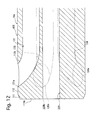
- FIG. 12 is a sectional view taken along the line XII-XII of FIG. 11 ;
- FIG. 13 is a perspective view showing the configuration of the internal treatment apparatus for a patient of FIG. 11 with surgical instruments and an endoscope being inserted therein;
- FIG. 14 is a block diagram showing the relation between a body, an endoscope, and surgical instruments, and body manipulating device, endoscope manipulating device, surgical instrument manipulating device, and image displaying device according to the second embodiment of the present invention
- FIG. 15 shows a modification of the second embodiment, of the present invention, and corresponds to FIG. 8 ;
- FIG. 16 is a perspective view showing the configuration of the internal treatment apparatus with surgical instruments and an endoscope being inserted therein in the modified second embodiment shown in FIG. 15 ;
- FIG. 17 shows another modification of the second embodiment of the present invention, corresponding to FIG. 8 ;
- FIG. 18 is a perspective view showing the configuration of the internal treatment apparatus with surgical instruments and an endoscope being inserted therein in the modified second embodiment shown in FIG. 17 ;
- FIG. 19 shows another modification of the second embodiment of the present invention.
- An internal treatment apparatus 200 and an internal treatment system 300 which are intended to perform a medical treatment on a site of lesion (target site) inside a patient, include an apparatus body 10 having a center opening 20 and a circumferential opening portion 30 .
- the internal treatment system 300 also includes a body manipulating device 60 , endoscope manipulating device 70 , and surgical instrument manipulating devices 81 to 85 .
- This embodiment to be described is provided with the circumferential opening portion 30 having five apertures; however, any number of apertures may be included in the circumferential opening portion 30 .
- the apparatus body 10 which is a flexible tubular member to be introduced into a patient (subject), may have an outer diameter of 5 cm.
- the apparatus body 10 has a distal end portion 11 having a circular cross section with its outer diameter reduced toward the distal end thereof, and a resiliently deflectable portion 12 secured to a rear end face 11 a of the distal end portion 11 .
- the apparatus body 10 is introduced into a patient from the tip of the distal end portion 11 so as to access deep inside the patient according to the location of a site of lesion.
- the apparatus body 10 allows the body manipulating device 60 connected to its proximal end portion to introduce or withdraw the apparatus body 10 into or from the patient and adjust the degree of deflection of the deflectable portion 12 .
- the body manipulating device 60 includes a manual device for the operator to manipulate manually, an automatic feed device, and a winding device, which allow the body manipulating device 60 to make the apparatus body 10 operable from outside the patient.
- the apparatus body 10 is provided with the center opening 20 , circular in cross section and extending through the center of the cross section thereof, through which an endoscope is inserted for a site of lesion (target site) to be observed.
- the apparatus body 10 is also provided with the circumferential opening portion 30 of five apertures 31 , 32 , 33 , 34 , and 35 , which are arranged at equal angular intervals (angular intervals of 72 degrees) about a center 20 a of the center opening 20 and extend through the apparatus body 10 , so that surgical instruments can be fed therethrough in order for surgical procedures to be performed on the site of lesion.
- the apertures 31 , 32 , 33 , 34 , and 35 each can have an inner diameter of 1.2 cm.
- the distal end portion 11 and the center opening 20 may not necessarily be circular in cross section.
- the five apertures 31 , 32 , 33 , 34 , and 35 may be preferably arranged to surround the center opening 20 at equi-angular intervals between adjacent apertures.
- the center opening 20 and the circumferential opening portion 30 may penetrate through only the distal end portion 11 with the deflectable portion 12 made hollow.
- a stereoscopic endoscope 21 is retractably inserted into and extends through the center opening 20 .
- the stereoscopic endoscope 21 has the following components fixedly inserted into a resiliently deflectable cylindrical body 21 a: two monitor optical systems 21 b and 21 c for stereoscopically observing a site of lesion, illumination optical systems 21 d and 21 e for illuminating the site of lesion with light, an air feed line 21 f for feeding air into the patient, and a water feed line 21 g for feeding water to the monitor optical systems 21 b and 21 c to defog or clean the surface thereof.
- the stereoscopic endoscope 21 is employed in this manner to observe a site of lesion and the surrounding area thereof stereoscopically, thereby making it possible to perform medical treatment precisely and smoothly. Furthermore, the stereoscopic endoscope 21 is connected at the proximal end portion thereof to the endoscope manipulating device 70 for introducing and withdrawing the body 21 a ; adjusting the focus, field of view, and zooming of the monitor optical systems 21 b and 21 c ; adjusting the brightness, direction, and angle of the illumination optical systems 21 d and 21 e ; feeding water to the monitor optical systems 21 b and 21 c to defog or clean the surface thereof; and feeding air into the patient.
- the endoscope manipulating device 70 allows the stereoscopic endoscope 21 to be operable from outside the patient.
- the monitor optical systems 21 b and 21 c are connected at the proximal end portion of the stereoscopic endoscope 21 to image displaying device 87 which is capable of displaying stereoscopically the images of the site of lesion and its surrounding provided thereby. It is also acceptable to employ only a single monitor optical system depending on the contents of medical treatment.
- Flexible elongated surgical instruments 41 , 42 , 43 , 44 , and 45 are retractably inserted into and extend out of the apertures 31 , 32 , 33 , 34 , and 35 , respectively.
- the surgical instruments 41 , 42 , 43 , 44 , and 45 which each have a resiliently deflectable portion, are connected at their respective proximal end portions to the surgical instrument manipulating devices 81 , 82 , 83 , 84 , and 85 to manipulate the surgical instruments.
- the surgical instruments 41 , 42 , 43 , 44 , and 45 may be inserted into any of the apertures 31 , 32 , 33 , 34 , and 35 depending on the order of medical treatment steps or the shape of a site of lesion.
- any surgical instruments other than the surgical instruments 41 , 42 , 43 , 44 , and 45 can also be inserted into the apertures 31 , 32 , 33 , 34 , and 35 .
- the apertures 31 , 32 , 33 , 34 , and 35 each have an inner diameter of 1.2 cm
- each of the surgical instruments 41 , 42 , 43 , 44 , and 45 can have an outer diameter of 1 cm.
- the surgical instrument 41 has the following components fixedly inserted into a resiliently deflectable cylindrical body 41 a to grasp the surrounding of the site of lesion for excision with the surgical instrument 42 or 45 : a grasper forceps 41 b capable of grasping an object; a monitor optical system (monitor device) 41 c for observing the vicinity of the tips of the grasper forceps 41 b ; illumination optical systems (illumination device) 41 d and 41 e for illuminating the vicinity of the tips of the grasper forceps 41 b with light; an air feed line 41 f (air feed device) for feeding air into the patient; and a water feed line 41 g (water feed device) for feeding water to the monitor optical system 41 c to defog or clean the surface thereof.
- a grasper forceps 41 b capable of grasping an object
- a monitor optical system (monitor device) 41 c for observing the vicinity of the tips of the grasper forceps 41 b
- the surgical instrument 41 is connected at the proximal end portion thereof to the surgical instrument manipulating device 81 for introducing, withdrawing, and deflecting the body 41 a ; controlling the grasping operation of the grasper forceps 41 b ; adjusting the focus, field of view, and zooming of the monitor optical system 41 c ; adjusting the brightness, direction, and angle of the illumination optical systems 41 d and 41 e ; and feeding water to the monitor optical system 41 c to defog or clean the surface thereof and feeding air into the patient.
- the surgical instrument manipulating device 81 allows the surgical instrument 41 to be operable from outside the patient.
- the monitor optical system 41 c is connected at the proximal end portion of the surgical instrument 41 to image displaying device 91 which is capable of displaying the image of the vicinity of the tips of the grasper forceps 41 b provided by the monitor optical system 41 c .
- Two monitor optical systems may also be employed to stereoscopically observe the vicinity of the tips of the grasper forceps 41 b. It is also possible to make infrared light observations, fluorescent light observations, zoomed observations, ultrasonic observations, confocal observations, or optical coherent tomographic (OCT) observations.
- the surgical instrument 42 has the following components fixedly inserted into a resiliently deflectable cylindrical body 42 a to sever the site of lesion whose surrounding is grasped with the surgical instrument 41 : a cutting forceps 42 b capable of severing an object; a monitor optical system (monitor device) 42 c for observing the vicinity of the tips of the cutting forceps 42 b ; illumination optical systems (illumination device) 42 d and 42 e for illuminating the vicinity of the tips of the cutting forceps 42 b with light; an air feed line 42 f (air feed device) for feeding air into the patient; and a water feed line 42 g (water feed device) for feeding water to the monitor optical system 42 c to defog or clean the surface thereof.
- a cutting forceps 42 b capable of severing an object
- a monitor optical system monitoring device
- illumination optical systems illumination device
- 42 d and 42 e for illuminating the vicinity of the tips of the cutting forceps 42
- the surgical instrument 42 is connected at its proximal end portion to the surgical instrument manipulating device 82 for introducing, withdrawing, and deflecting the body 42 a ; controlling the severing operation of the cutting forceps 42 b ; adjusting the focus, field of view, and zooming of the monitor optical system 42 c ; adjusting the brightness, direction, and angle of the illumination optical systems 42 d and 42 e ; and feeding water to the monitor optical system 42 c to defog or clean the surface thereof and feeding air into the patient.
- the surgical instrument manipulating device 82 makes the surgical instrument 42 operable from outside the patient.
- the monitor optical system 42 c is connected at the proximal end portion of the surgical instrument 42 to image displaying device 92 which is capable of displaying the image of the vicinity of the tips of the cutting forceps 42 b provided by the monitor optical system 42 c .
- Two monitor optical systems may also be employed to stereoscopically observe the vicinity of the tips of the cutting forceps 42 b. It is also possible to make infrared light observations, fluorescent light observations, zoomed observations, ultrasonic observations, confocal observations, or optical coherent tomographic observations (OCT).
- the surgical instrument 43 has the following components fixedly inserted into a resiliently deflectable cylindrical body 43 a to feed water for cleaning the site of lesion and the surrounding area thereof and apply suction to a liquid such as blood or cleaning water at the site of lesion and the surrounding area thereof.
- the components include a cleaning water feed/suction tube 43 b for feeding water to clean the site of lesion and the surrounding area thereof and applying suction to a liquid such as blood or cleaning water at the site of lesion and the surrounding area thereof from outside the patient; a monitor optical system (monitor device) 43 c for observing the vicinity of the tip of the cleaning water feed/suction tube 43 b ; illumination optical systems (illumination device) 43 d and 43 e for illuminating the vicinity of the tip of the cleaning water feed/suction tube 43 b with light; and an air feed line 43 f (air feed device) for feeding air into the patient and a water feed line 43 g (water feed device) for feeding water to the monitor optical system 43 c to defog or clean the surface thereof.
- a monitor optical system monitoring device
- illumination optical systems illumination device
- 43 d and 43 e for illuminating the vicinity of the tip of the cleaning water feed/suction tube 43 b with light
- an air feed line 43 f
- the surgical instrument 43 is connected at its proximal end portion to the surgical instrument manipulating device 83 for introducing, withdrawing, and deflecting the body 43 a ; controlling the feeding of water and applications of suction by the cleaning water feed/suction tube 43 b ; adjusting the focus, field of view, and zooming of the monitor optical system 43 c ; adjusting the brightness, direction, and angle of the illumination optical systems 43 d and 43 e ; and feeding water to the monitor optical system 43 c to defog or clean the surface thereof and feeding air into the patient.
- the surgical instrument manipulating device 83 makes the surgical instrument 43 operable from outside the patient.
- the monitor optical system 43 c is connected at the proximal end portion of the surgical instrument 43 to image displaying device 93 which is capable of displaying the image of the vicinity of the tip of the cleaning water feed/suction tube 43 b provided by the monitor optical system 43 c .
- Two monitor optical systems may also be employed to stereoscopically observe the vicinity of the tip of the cleaning water feed/suction tube 43 b . It is also possible to make infrared light observations, fluorescent light observations, zoomed observations, ultrasonic observations, confocal observations, or optical coherent tomographic (OCT) observations.
- the surgical instrument 44 has the following components fixedly inserted into a resiliently deflectable cylindrical body 44 a to locally stop bleeding at a desired portion: an RF hemostatic forceps 44 b for applying a radio frequency to a desired portion and thereby generating heat to stop bleeding; a monitor optical system (monitor device) 44 c for observing the vicinity of the tips of the RF hemostatic forceps 44 b ; illumination optical systems (illumination devices) 44 d and 44 e for illuminating the vicinity of the tips of the RF hemostatic forceps 44 b with light; an air feed line 44 f (air feed device) for feeding air into the patient; and a water feed line 44 g (water feed device) for feeding water to the monitor optical system 44 c to defog or clean the surface thereof.
- an RF hemostatic forceps 44 b for applying a radio frequency to a desired portion and thereby generating heat to stop bleeding
- a monitor optical system (monitor device) 44 c for observing the vicinity of
- the surgical instrument 44 is connected at the proximal end portion thereof to the surgical instrument manipulating device 84 for introducing, withdrawing, and deflecting the body 44 a ; controlling the hemostatic operations provided by the RF hemostatic forceps 44 b ; adjusting the focus, field of view, and zooming of the monitor optical system 44 c ; adjusting the brightness, direction, and angle of the illumination optical systems 44 d and 44 e ; and feeding water to the monitor optical system 44 c to defog or clean the surface thereof and feeding air into the patient.
- the surgical instrument manipulating device 84 allows the surgical instrument 44 to be operable from outside the patient.
- the monitor optical system 44 c is connected at the proximal end portion of the surgical instrument 44 to an image displaying device 94 which is capable of displaying the image of the vicinity of the tips of the RF hemostatic forceps 44 b provided by the monitor optical system 44 c .
- Two monitor optical systems may also be employed to stereoscopically observe the vicinity of the tips of the RF hemostatic forceps 44 b . It is also possible to make infrared light observations, fluorescent light observations, zoomed observations, ultrasonic observations, confocal observations, or optical coherent tomographic observations (OCT).
- the surgical instrument 45 has the following components fixedly inserted into a resiliently deflectable cylindrical body 45 a to incise a desired portion: an RF incision knife 45 b for pushing its RF-vibrating tip portion against a desired portion for incision; a monitor optical system (monitor device) 45 c for observing the vicinity of the tip of the RF incision knife 45 b ; illumination optical systems (illumination device) 45 d and 45 e for illuminating the vicinity of the tip of the RF incision knife 45 b with light; an air feed line 45 f (air feed device) for feeding air into the patient; and a water feed line 45 g (water feed device) for feeding water to the monitor optical system 45 c to defog or clean the surface thereof.
- an RF incision knife 45 b for pushing its RF-vibrating tip portion against a desired portion for incision
- a monitor optical system (monitor device) 45 c for observing the vicinity of the tip of the RF incision knife 45
- the surgical instrument 45 is connected at the proximal end portion thereof to the surgical instrument manipulating device 85 for introducing, withdrawing, and deflecting the body 45 a ; controlling the incision operations provided by the RF incision knife 45 b ; adjusting the focus, field of view, and zooming of the monitor optical system 45 c ; adjusting the brightness, direction, and angle of the illumination optical systems 45 d and 45 e ; and feeding water to the monitor optical system 45 c to defog or clean the surface thereof and feeding air into the patient.
- the surgical instrument manipulating device 85 allows the surgical instrument 45 to be operable from outside the patient.
- the monitor optical system 45 c is connected at the proximal end portion of the surgical instrument 45 to image displaying device 95 which is capable of displaying the image of the vicinity of the tip of the RF incision knife 45 b provided by the monitor optical system 45 c .
- Two monitor optical systems may also be employed to stereoscopically observe the vicinity of the tip of RF incision knife 45 b . It is also possible to make infrared light observations, fluorescent light observations, zoomed observations, ultrasonic observations, confocal observations, or optical coherent tomographic observations (OCT).
- an adequate portion is incised to perform the surgical procedure on a site of lesion in a patient.
- the internal treatment apparatus 200 only requires an incised portion just large enough to introduce therethrough the internal treatment apparatus 200 into the patient (e.g., about 5 cm for the apparatus body 10 having an outer diameter of 5 cm), thereby reducing the burden on the patient.
- the internal treatment apparatus 200 is introduced into a patient 50 through the incised portion.
- the body manipulating device 60 is connected to the apparatus body 10
- the endoscope manipulating device 70 and the image displaying device 87 are connected to the stereoscopic endoscope 21
- the surgical instrument manipulating devices 81 through 85 are connected to the surgical instruments 41 through 45 , respectively
- the image displaying devices 91 through 95 are connected to the surgical instruments 41 through 45 , respectively, as shown in FIG. 3 .
- the internal treatment apparatus 200 is introduced into the patient and then stopped, so as to commence the surgical procedure when a view range 22 of the stereoscopic endoscope 21 allows the operator to view a lesion 55 and the surrounding area thereof and each tip portion of the surgical instruments 41 , 42 , 43 , 44 , and 45 , as shown in FIG. 4 .
- the internal treatment apparatus 200 is designed such that the surgical instruments 41 through 45 are arranged to surround the stereoscopic endoscope 21 , thereby allowing the surgical instruments 41 through 45 to be placed along the entire circumference of a view range provided by the stereoscopic endoscope 21 during the surgical procedure. This allows the operator to easily recognize the lesion 55 and the surgical instruments 41 through 45 , thereby facilitating the manipulation thereof. Additionally, the surgical instruments can be replaced as appropriate to facilitate a surgical operation. For example, as shown in FIG. 4 , two grasper forceps 41 b can be used to elevate the lesion 55 at the left and right sides thereof.
- the RF incision knife 45 b is then used to sever the lesion 55 at a base thereof, and the RF hemostatic forceps 44 b and the cleaning water feed/suction tube 43 b are then used to stop bleeding and feed cleaning water from above as required. Furthermore, for a lesion 55 located deep inside the patient, the internal treatment apparatus 200 can be introduced deep into the patient to provide a view range as shown in FIG. 4 , thereby allowing the surgical procedure to be performed smoothly with safety.
- the resiliently deflectable cylindrical bodies 41 a, 42 a , 43 a , 44 a , and 45 a can be replaced with endoscopic insertion portions 141 a , 142 a , 143 a , 144 a , and 145 a , respectively.
- the grasper forceps 41 b , the cutting forceps 42 b , the cleaning water feed/suction tube 43 b, the RF hemostatic forceps 44 b , and the RF incision knife 45 b are passed through forceps channels 141 h , 142 h , 143 h, 144 h , and 145 h which are provided in the endoscopic insertion portions 141 a , 142 a , 143 a , 144 a , and 145 a , respectively.
- the endoscopic insertion portions 141 a , 142 a , 143 a , 144 a , and 145 a are provided with a monitor optical system, an illumination optical system, an air feed line, a water feed line, and a deflectable portion. This configuration allows for utilizing an existing endoscope, thereby reducing manufacturing costs.
- the body manipulating device 60 , the endoscope manipulating device 70 , and the surgical instrument manipulating devices 81 through 85 can be replaced with a manipulating device 160 which allows the operator to collectively or selectively manipulate the apparatus body 10 , the stereoscopic endoscope 21 , and the surgical instruments 41 through 45 .
- the image displaying device 87 and the image displaying device 91 through 95 can be replaced with an image display device 190 which can collectively or selectively display images from the monitor optical systems 21 b and 21 c of the stereoscopic endoscope 21 and from the monitor optical systems 41 c , 42 c , 43 c , 44 c , and 45 c of the surgical instruments 41 through 45 .
- This configuration provides a space-saving, compact system, allowing a less number of operators to efficiently perform surgical procedures.
- An internal treatment apparatus 400 and an internal treatment system 500 ( FIG. 14 ) according to the second embodiment, which are intended to perform a medical treatment on a site of lesion (target site) inside a patient, include an apparatus body 10 a having a center opening 220 and a circumferential opening portion 130 .
- the internal treatment system 500 further includes a body manipulating device 260 , a endoscope manipulating device 170 , and surgical instrument manipulating devices 181 and 182 .
- the apparatus body 10 a can be formed as a flexible tubular member to be introduced into a patient (subject). As shown in FIG. 9 , the apparatus body 10 a includes a distal end portion 111 having a circular cross section with the outer diameter thereof reduced toward its distal end, and a resiliently deflectable portion 112 secured to a rear end face 111 a of the distal end portion 111 . The apparatus body 10 a is introduced into a patient from the tip of the distal end portion 111 so as to reach deep inside the patient to the location of a site of lesion. The apparatus body 10 a allows the body manipulating device 260 ( FIG.
- the body manipulating device 260 includes a manual device for the operator for manual manipulation, an automatic feed device, and a winding device, which allows the body manipulating device 260 to make the apparatus body 10 a operable from outside the patient.
- the cylindrical apparatus body 10 a is provided with the circular center opening 220 , which passes through the apparatus body 10 a from the center of one bottom face (distal end face) 111 b of the two bottom faces, the bottom face 111 b facing the lesion 55 , toward the other bottom face (proximal end face, not shown).
- the apparatus body 10 a is further provided with the circumferential opening portion 130 which passes through the apparatus body 10 a from a side face 112 b of the deflectable portion 112 toward a proximal end face 10 c ( FIG. 14 ) of the apparatus body 10 a .
- a stereoscopic endoscope 221 for observing a site of lesion is inserted through the center opening 220 to protrude from an outlet 220 b to the lesion 55 .
- the circumferential opening portion 130 includes two circular apertures 131 and 132 disposed at equi-angular intervals (at intervals of 180 degrees in this embodiment) about a center 220 a of the center opening 220 .
- Surgical instruments 242 and 241 for performing a surgical procedure on a site of lesion are passed through the apertures 131 and 132 to protrude outwardly from outlets 131 a and 132 a , respectively.
- the distance between the outlet 131 a and the distal end face 111 b is equal to that between the outlet 132 a and the distal end face 111 b .
- the outlets 131 a and 132 a being preferably equal in inner diameter would allow the surgical instruments 241 and 242 to be replaced according to the contents and steps of surgical procedures. It is also desirable to make the inner diameter of the outlets 131 a and 132 a greater than the outer diameter of the surgical instruments 241 and 242 to use the surgical instruments 241 and 242 at desired angles.
- the apparatus body 10 a having the apertures 131 and 132 can be formed according to an existing technique. For example, it is possible to form the apparatus body 10 a having the apertures 131 and 132 by molding a heat meltable resin in a mold having a cylindrical portion the same in shape as the apertures 131 and 132 and then solidifying the resin by cooling.
- the apertures 131 and 132 formed in this manner would prevent the endoscope and two surgical instruments from being entangled or interfering with each other inside the apparatus body 10 a , thereby eliminating the difficulty of manipulating them.
- the apparatus body 10 a formed as described above may have an outer diameter of 5 cm with the apertures 131 and 132 each having an inner diameter of 1.2 cm.
- the distal end portion 111 and the center opening 220 may have not necessarily to be circular in cross section.
- the stereoscopic endoscope 221 has the following components fixedly inserted into a resiliently deflectable cylindrical body 221 a .
- the components include two monitor optical systems 221 b and 221 c for stereoscopically observing a site of lesion; illumination optical systems 221 d and 221 e for illuminating the site of lesion with light; an air feed line 221 f for feeding air into the patient; and a water feed line 221 g for feeding water to the monitor optical systems 221 b and 221 c to defog or clean the surface thereof.
- the stereoscopic endoscope 221 is employed in this manner to observe a site of lesion and the surrounding area thereof stereoscopically, thereby making it possible to perform medical treatment precisely and smoothly. Furthermore, as shown in FIG. 14 , the stereoscopic endoscope 221 is connected at the proximal end portion thereof to the endoscope manipulating device 170 for introducing and withdrawing the body 221 a ; adjusting the focus, field of view, and zooming of the monitor optical systems 221 b and 221 c ; adjusting the brightness, direction, and angle of the illumination optical systems 221 d and 221 e ; and feeding water to the monitor optical systems 221 b and 221 c to defog or clean the surface thereof and feeding air into the patient.
- the monitor optical systems 221 b and 221 c are connected at the proximal end portion of the stereoscopic endoscope 221 to image displaying device 187 which is capable of displaying stereoscopically the images of the site of lesion and its surrounding provided thereby. It is also possible to employ only a single monitor optical system depending on the contents of medical treatments.
- the surgical instrument 241 has the following components fixedly inserted into a resiliently deflectable cylindrical body 241 a to sever the site of lesion whose surrounding is grasped with the surgical instrument 242 : a cutting forceps 241 b capable of severing an object; a monitor optical system (monitor device) 241 c for observing the vicinity of the tips of the cutting forceps 241 b ; illumination optical systems (illumination device) 241 d and 241 e for illuminating the vicinity of the tips of the cutting forceps 241 b with light; and an air feed line 241 f (air feed device) for feeding air into the patient and a water feed line 241 g (water feed device) for feeding water to the monitor optical system 241 c to defog or clean the surface thereof.
- a cutting forceps 241 b capable of severing an object
- a monitor optical system monitoring device
- illumination optical systems illumination device
- 241 d and 241 e for il
- the surgical instrument 241 is connected at the proximal end portion thereof to the surgical instrument manipulating device 181 for introducing, withdrawing, and deflecting the body 241 a ; controlling the severing operation of the cutting forceps 241 b ; adjusting the focus, field of view, and zooming of the monitor optical system 241 c ; adjusting the brightness, direction, and angle of the illumination optical systems 241 d and 241 e ; and feeding water to the monitor optical system 241 c to defog or clean the surface thereof and feeding air into the patient.
- This allows the surgical instrument manipulating device 181 to make the surgical instrument 241 operable from outside the patient.
- the monitor optical system 241 c is connected at the proximal end portion of the surgical instrument 241 to an image displaying device 191 which is capable of displaying the image of the vicinity of the tips of the cutting forceps 241 b provided by the monitor optical system 241 c .
- Two monitor optical systems may also be employed to stereoscopically observe the vicinity of the tips of the cutting forceps 241 b . It is also possible to make infrared light observations, fluorescent light observations, zoomed observations, ultrasonic observations, confocal observations, or optical coherent tomographic (OCT) observations.
- the surgical instrument 242 has the following components fixedly inserted into a resiliently deflectable cylindrical body 242 a to sever the site of lesion whose surrounding is grasped with the surgical instrument 241 : a cutting forceps 242 b capable of severing an object; a monitor optical system (monitor device) 242 c for observing the vicinity of the tips of the cutting forceps 242 b ; illumination optical systems (illumination device) 242 d and 242 e for illuminating the vicinity of the tips of the cutting forceps 242 b with light; and an air feed line 242 f (air feed device) for feeding air into the patient and a water feed line 242 g (water feed device) for feeding water to the monitor optical system 242 c to defog or clean the surface thereof.
- a cutting forceps 242 b capable of severing an object
- a monitor optical system monitoring device
- illumination optical systems illumination device
- 242 d and 242 e for il
- the surgical instrument 242 is connected at its proximal end portion to the surgical instrument manipulating device 182 for introducing, withdrawing, and deflecting the body 242 a ; controlling the severing operation of the cutting forceps 242 b ; adjusting the focus, field of view, and zooming of the monitor optical system 242 c ; adjusting the brightness, direction, and angle of the illumination optical systems 242 d and 242 e ; and feeding water to the monitor optical system 242 c to defog or clean the surface thereof and feeding air into the patient.
- This allows the surgical instrument manipulating device 182 to make the surgical instrument 242 operable from outside the patient.
- the monitor optical system 242 c is connected at the proximal end portion of the surgical instrument 242 to an image displaying device 192 which is capable of displaying the image of the vicinity of the tips of the cutting forceps 242 b provided by the monitor optical system 242 c .
- Two monitor optical systems may also be employed to stereoscopically observe the vicinity of the tips of the cutting forceps 242 b . It is also possible to make infrared light observations, fluorescent light observations, zoomed observations, ultrasonic observations, confocal observations, or optical coherent tomographic (OCT) observations.
- the surgical instruments 241 and 242 may be inserted into any of the apertures 131 and 132 depending on the order of medical treatment steps or the shape of a site of lesion. Any surgical instruments other than the surgical instruments 241 and 242 can also be inserted into the apertures 131 and 132 . For example, assuming that the apertures 131 and 132 each have an inner diameter of 1.2 cm, each of the surgical instruments 241 and 242 can have an outer diameter of 1 cm.
- the stereoscopic endoscope 221 protrudes from the distal end face 111 b while the surgical instruments 241 and 242 are protruded from the side faces, thereby reducing the risk of the surgical instruments 241 and 242 being tangled with each other inside the patient 50 . Accordingly, the stereoscopic endoscope 221 and the surgical instruments 241 and 242 can be easily placed at desired positions. Furthermore, as shown in FIG. 10 , the surgical instruments 241 and 242 access the lesion 55 from right and left sides within the view range provided by the stereoscopic endoscope 221 , thereby allowing the operator to view an enlarged range without being obstructed by the surgical instruments 241 and 242 .
- the circumferential opening portion 130 includes any number of apertures in the circumferential opening portion 130 .
- five apertures can be employed in the circumferential opening portion 130 .
- the circumferential opening portion 130 includes five apertures 131 , 132 , 133 , 134 , and 135 .
- the apertures 131 , 132 , 313 , 134 , and 135 are disposed at equi-angular intervals (angular intervals of 72 degrees) about a center 220 a of the center opening 220 to extend through the apparatus body 10 a to reach circular outlets 131 a , 132 a , 133 a , 134 a , and 135 a provided on the side face 112 b , respectively.
- the outlets 131 a , 132 a, 133 a , 134 a , and 135 a are disposed at the equal distance from the distal end face 111 b .
- the aforementioned flexible elongated surgical instruments 241 , 242 , 243 , 244 , and 245 are retractably inserted into and penetrate the apertures 131 , 132 , 133 , 134 , and 135 , respectively.
- the surgical instrument 243 has the following components fixedly inserted into a resiliently deflectable cylindrical body 243 a to feed water for cleaning the site of lesion and its surrounding and apply suction to a liquid such as blood or cleaning water at the site of lesion and the surrounding area thereof.
- the components include a cleaning water feed/suction tube 243 b for feeding water to clean the site of lesion and the surrounding area thereof and applying suction to a liquid such as blood or cleaning water at the site of lesion and its surrounding from outside the patient; a monitor optical system (monitor device) 243 c for observing the vicinity of the tip of the cleaning water feed/suction tube 243 b ; illumination optical systems (illumination device) 243 d and 243 e for illuminating the vicinity of the tip of the cleaning water feed/suction tube 243 b with light; and an air feed line 243 f (air feed device) for feeding air into the patient and a water feed line 243 g (water feed device) for feeding water to the monitor optical system 243 c to defog or clean the surface thereof.
- a monitor optical system monitoring device
- illumination optical systems illumination device
- 243 d and 243 e for illuminating the vicinity of the tip of the cleaning water feed/suction tube 243 b with
- the surgical instrument 243 is connected at its proximal end portion to surgical instrument manipulating device (not shown) for introducing, withdrawing, and deflecting the body 243 a ; controlling the feeding of water and applications of suction by the cleaning water feed/suction tube 243 b ; adjusting the focus, field of view, and zooming of the monitor optical system 243 c ; adjusting the brightness, direction, and angle of the illumination optical systems 243 d and 243 e ; and feeding water to the monitor optical system 243 c to defog or clean the surface thereof and feeding air into the patient.
- This surgical instrument manipulating device allows the surgical instrument 243 to be operable from outside the patient.
- the monitor optical system 243 c is connected at the proximal end portion of the surgical instrument 243 to image displaying device (not shown) which is capable of displaying the image of the vicinity of the tip of the cleaning water feed/suction tube 243 b provided by the monitor optical system 243 c .
- Two monitor optical systems may also be employed to stereoscopically observe the vicinity of the tip of the cleaning water feed/suction tube 243 b . It is also possible to make infrared light observations, fluorescent light observations, zoomed observations, ultrasonic observations, confocal observations, or optical coherent tomographic(OCT) observations.
- the surgical instrument 244 has the following components fixedly inserted into a resiliently deflectable cylindrical body 244 a to locally stop bleeding at a desired portion.
- the components include an RF hemostatic forceps 244 b for applying a radio frequency locally to a desired portion and thereby generating heat to stop bleeding; a monitor optical system (monitor device) 244 c for observing the vicinity of the tips of the RF hemostatic forceps 244 b ; illumination optical systems (illumination device) 244 d and 244 e for illuminating the vicinity of the tips of the RF hemostatic forceps 244 b with light; and an air feed line 244 f (air feed device) for feeding air into the patient and a water feed line 244 g (water feed device) for feeding water to the monitor optical system 244 c to defog or clean the surface thereof.
- an RF hemostatic forceps 244 b for applying a radio frequency locally to a desired portion and thereby generating heat to stop bleeding
- the surgical instrument 244 is connected at its proximal end portion to surgical instrument manipulating device (not shown) for introducing, withdrawing, and deflecting the body 244 a ; controlling the hemostatic operations provided by the RF hemostatic forceps 244 b ; adjusting the focus, field of view, and zooming of the monitor optical system 244 c ; adjusting the brightness, direction, and angle of the illumination optical systems 244 d and 244 e ; and feeding water to the monitor optical system 244 c to defog or clean the surface thereof and feeding air into the patient.
- This surgical instrument manipulating device allows the surgical instrument 244 to be operable from outside the patient.
- the monitor optical system 244 c is connected at the proximal end portion of the surgical instrument 244 to image displaying device (not shown) which is capable of displaying the image of the vicinity of the tips of the RF hemostatic forceps 244 b provided by the monitor optical system 244 c .
- image displaying device (not shown) which is capable of displaying the image of the vicinity of the tips of the RF hemostatic forceps 244 b provided by the monitor optical system 244 c .
- Two monitor optical systems may also be employed to stereoscopically observe the vicinity of the tips of the RF hemostatic forceps 244 b . It is also possible to make infrared light observations, fluorescent light observations, zoomed observations, ultrasonic observations, confocal observations, or optical coherent tomographic (OCT) observations.
- the surgical instrument 245 has the following components fixedly inserted into a resiliently deflectable cylindrical body 245 a to incise a desired portion.
- the components include an RF incision knife 245 b for pushing its RF-vibrating tip portion against a desired portion for incision; a monitor optical system (monitor device) 245 c for observing the vicinity of the tip of the RF incision knife 245 b ; illumination optical systems (illumination device) 245 d and 245 e for illuminating the vicinity of the tip of the RF incision knife 245 b with light; and an air feed line 245 f (air feed device) for feeding air into the patient and a water feed line 245 g (water feed device) for feeding water to the monitor optical system 245 c to defog or clean the surface thereof.
- air feed line 245 f air feed device
- water feed line 245 g water feed device
- the surgical instrument 245 is connected at its proximal end portion to surgical instrument manipulating device (not shown) for introducing, withdrawing, and deflecting the body 245 a ; controlling the incision operations provided by the RF incision knife 245 b ; adjusting the focus, field of view, and zooming of the monitor optical system 245 c ; adjusting the brightness, direction, and angle of the illumination optical systems 245 d and 245 e ; and feeding water to the monitor optical system 245 c to defog or clean the surface thereof and feeding air into the patient.
- This surgical instrument manipulating device allows the surgical instrument 245 to be operable from outside the patient.
- the monitor optical system 245 c is connected at the proximal end portion of the surgical instrument 245 to image displaying device (not shown) which is capable of displaying the image of the vicinity of the tip of the RF incision knife 245 b provided by the monitor optical system 245 c .
- image displaying device (not shown) which is capable of displaying the image of the vicinity of the tip of the RF incision knife 245 b provided by the monitor optical system 245 c .
- Two monitor optical systems may also be employed to stereoscopically observe the vicinity of the tip of the RF incision knife 245 b. It is also possible to make infrared light observations, fluorescent light observations, zoomed observations, ultrasonic observations, confocal observations, or optical coherent tomographic (OCT) observations.
- OCT optical coherent tomographic
- the surgical instruments 241 , 242 , 243 , 244 , and 245 being preferably equal in outer diameter could be inserted into any aperture according to the contents and steps of the surgical procedure. It is also desirable to make the inner diameter of the outlets 131 a , 132 a , 133 a , 134 a , and 135 a greater than the outer diameter of the surgical instruments 241 , 242 , 243 , 244 , and 245 to use the surgical instruments 241 , 242 , 243 , 244 , and 245 at desired angles.
- FIGS. 7 through 9 The following is an explanation on a surgical procedure performed on a site of lesion using the internal treatment apparatus 400 and the internal treatment system 500 , shown in FIGS. 7 through 9 .
- an adequate portion is incised to perform a surgical procedure on a site of lesion in a patient.
- the internal treatment apparatus 400 would require an incised portion just large enough to introduce therethrough the internal treatment apparatus 400 into the patient (e.g., about 5 cm for the apparatus body 10 a having an outer diameter of 5 cm), thereby reducing the burden on the patient.
- the internal treatment apparatus 400 is introduced into a patient 50 through the incised portion.
- the body manipulating device 260 , the endoscope manipulating device 170 , the surgical instrument manipulating devices 181 and 182 , and the image displaying device 187 and 191 have been already connected to the apparatus body 10 a , the stereoscopic endoscope 221 , and the surgical instruments 241 and 242 in the internal treatment apparatus 400 .
- the surgical instruments 241 and 242 are preferably accommodated inside the apparatus body 10 a without being protruded from the outlets 131 a and 132 a by manipulating the surgical instrument manipulating devices 181 and 182 .
- the internal treatment apparatus 400 is introduced into the patient and then stopped to start the surgical procedure when a view range 22 of the stereoscopic endoscope 221 allows the operator to view a lesion 55 and the surrounding area thereof and each tip portion of the surgical instruments 241 , 242 , as shown in FIG. 10 .
- the internal treatment apparatus 400 is designed such that the surgical instruments 241 and 242 are arranged to surround the stereoscopic endoscope 221 , thereby allowing the surgical instruments 241 and 242 to come into the view provided by the stereoscopic endoscope 221 from its periphery during the surgical procedure. This allows the operator to easily recognize the lesion 55 and the surgical instruments 241 and 242 , thereby facilitating the manipulation thereof. Furthermore, the stereoscopic endoscope 221 is protruded from the distal end face 111 b while the surgical instruments 241 and 242 are protruded from the side face 112 b , thereby reducing the risk of the surgical instruments 241 and 242 being interfered with each other. Accordingly, for a lesion 55 located deep inside the patient, the internal treatment apparatus 400 can be introduced deep into the patient, thereby performing the surgical procedure smoothly and with safety. The following are explanations of modifications of the second embodiment, according to the present invention.
- the illumination light which is emitted from the illumination optical systems 221 d and 221 e can be white light, and the illumination light which is emitted from each of the illumination optical systems 241 d , 241 e , 242 d , 242 e , 243 d, 243 e , 244 d , 244 e , 245 d and 245 e can be colored light.
- the surgical instruments 241 through 245 are directed toward the center axis 10 b of the apparatus body 10 a , colored light appears within the field-of-view of the stereoscopic endoscope 221 , and the farther the surgical instruments 241 through 245 are moved away from the center axis 10 b , the amount of colored light which appears within the field-of-view of the stereoscopic endoscope 221 decreases. If such a characteristic is utilized, operation of the surgical instruments 241 through 245 is facilitated because the bending direction of the surgical instruments 241 through 245 can be visually confirmed.
- the illumination light emitted from the illumination optical systems 221 d , 221 e, 241 d , 241 e , 242 d , 242 e, 243 d , 243 e , 244 d , 244 e , 245 d and 245 e is desirable for the illumination light emitted from the illumination optical systems 221 d , 221 e, 241 d , 241 e , 242 d , 242 e, 243 d , 243 e , 244 d , 244 e , 245 d and 245 e, to be changeable between white light and colored light.
- each colored light emitted from the surgical instruments 241 through 245 can be set so as to have a different wavelength from each other. Accordingly, the bending direction of each of the surgical instruments 241 through 245 can be visually confirmed individually.
- the white light and colored light can be continuous light or intermitting light, and if a combination of continuous light and intermitting light is applied, light emitted from the illumination optical systems 221 d and 221 e and light emitted from the illumination optical systems 221 d, 221 e , 241 d , 241 e , 242 d , 242 e, 243 d , 243 e , 244 d , 244 e , 245 d and 245 e can be easily distinguished visually.
- the wavelength of the colored light is altered in accordance with time, by changing the colored illumination state within the field-of-view of the stereoscopic endoscope 221 during an operation, an object under observation can be easily confirmed visually in the case where one illumination color is insufficient for observation throughout the duration of an operation.
- the intensity of light emitted from the illumination optical systems 221 d and 221 e can be made to differ from the intensity of light emitted from the illumination optical systems 221 d , 221 e , 241 d , 241 e , 242 d, 242 e , 243 d , 243 e , 244 d , 244 e , 245 d and 245 e .
- the light emitted from the illumination optical systems 221 d and 221 e and the light emitted from the illumination optical systems 221 d , 221 e , 241 d , 241 e , 242 d , 242 e , 243 d, 243 e , 244 d , 244 e , 245 d and 245 e can be easily distinguished, the bending directions of the surgical instruments 241 through 245 can be visually confirmed, facilitating the operation thereof.
- two circular apertures 231 and 232 are provided instead of the two circular apertures 131 and 132 .
- Two channels 231 b and 232 b of the two circular apertures 231 and 232 extend parallel to a center axis 10 b of an apparatus body 110 a , and are the same as two channels 131 b and 132 b , of the two circular apertures 131 and 132 , which extend parallel to the center axis 10 b of the apparatus body 10 a .
- Outlets 231 a and 232 a are provided closer to than the bottom face (distal end face) 111 b than the outlets 131 a and 132 a .
- the angle by which surgical instruments 341 and 342 (see FIG. 16 ) project out of the two circular apertures 231 and 232 of the apparatus body 110 a i.e., the angle with respect to the center axis 10 b of the apparatus body 110 a ) is smaller.
- FIG. 16 shows the internal treatment apparatus 600 with surgical instruments 341 and 342 being inserted into apertures 231 and 232 , respectively, in the modified second embodiment of FIG. 15 .
- the angle by which the surgical instrument 341 projects out of the apparatus body 110 a from the outlet 231 a i.e., the angle between the center axis 10 b and the surgical instrument 341 when extended in a straight line (center axis 341 h )
- the angle by which the surgical instrument 342 projects out of the apparatus body 110 a from the outlet 232 a i.e., the angle between the center axis 10 b and the surgical instrument 342 when extended in a straight line (center axis 342 h )
- B the angle between the center axis 10 b and the surgical instrument 342 when extended in a straight line
- the distal ends of the surgical instruments 341 and 342 can easily fit into the field-of-view of the stereoscopic endoscope 321 even if the surgical instruments 341 and 342 are projected outwards in a straight line, so that a safe and reliable treatment operation can be carried out quickly and easily.
- the projection angle of each of the surgical instruments 341 and 342 is smaller than ‘A’, i.e., the half-angle of the field-of-view of the stereoscopic endoscope 321 , the angle of each of the surgical instruments 341 and 342 can be set to a desired angle.
- two circular apertures 331 and 332 are provided instead of the two circular apertures 131 and 132 .
- Two channels 331 b and 332 b of the two circular apertures 331 and 332 extend parallel to a center axis 110 b of an apparatus body 210 a , and are the same as two channels 131 b and 132 b , of the two circular apertures 131 and 132 , which extend parallel to the center axis 10 b of the apparatus body 10 a .
- Outlets 331 a and 332 a are provided so as to extend over the resiliently deflectable portion 112 and the bottom face (distal end face) 111 b .
- the angle by which surgical instruments 441 and 442 (see FIG. 18 ) project out of the two circular apertures 331 and 332 of the apparatus body 210 a i.e., the angle with respect to the center axis 110 b of the apparatus body 210 a ) is smaller.
- FIG. 18 shows the internal treatment apparatus 700 with surgical instruments 441 and 442 being inserted into apertures 331 and 332 , respectively, in the modified second embodiment of FIG. 17 .
- the angle by which the surgical instrument 441 projects out of the apparatus body 210 a from the outlet 331 a i.e., the angle between the center axis 110 b and the surgical instrument 441 when extended in a straight line (center axis 441 h )
- the angle by which the surgical instrument 442 projects out of the apparatus body 210 a from the outlet 332 a i.e., the angle between the center axis 110 b and the surgical instrument 442 when extended in a straight line (center axis 442 h )
- C the angle between the center axis 110 b and the surgical instrument 442 when extended in a straight line
- the distal ends of the surgical instruments 441 and 442 can easily fit into the field-of-view of the stereoscopic endoscope 421 even if the surgical instruments 441 and 442 are projected outwards in a straight line, so that a safe and reliable treatment operation can be carried out quickly and easily.
- the projection angle of each of the surgical instruments 441 and 442 is smaller than ‘A’, i.e., the half-angle of the field-of-view of the stereoscopic endoscope 421 , the angle of each of the surgical instruments 441 and 442 can be set to a desired angle.
- grooves 541 through 545 having the same shape and concaved in a direction from the side face 212 b to the 10 b can be provided in each space between two adjacent outlets 431 a and 435 a (outlets 434 a and 435 a are not shown in FIG. 19 ) provided on the side face 212 b at equi-angular intervals around the center opening 320 .
- the grooves 541 through 545 can be of a desired shape so long as the amount of surface area to which the distal end portion 211 and the resiliently deflectable portion 212 touches internal tissue of the patient 50 can be reduced.
- surgical instruments can be placed at equal angular intervals around an endoscope for observing a target site. This reduces the length of an incised portion for surgical procedures performed on a site of lesion inside a patient even when a plurality of surgical instruments are introduced at the same time through the incised portion. Additionally, for a surgical procedure performed on a site of lesion located deep inside the patient, it is possible to ensure an adequate view range without increasing the length of the incised portion. Furthermore, the surgical instruments are placed so as to surround the endoscope for observing the site of lesion, thereby preventing the surgical instruments from interfering with each other and obstructing the view, and allowing the operator to perform the surgical procedure smoothly.
- an endoscope is protruded from a bottom face of the cylindrical body while surgical instruments are protruded from the side face.
- This configuration prevents the surgical instruments from obstructing the view window of the endoscope and restricting the field of view, thereby eliminating the difficulty of viewing the site of lesion and the surrounding area thereof.
- a plurality of surgical instruments could be introduced into the patient to access the site of lesion from the periphery of the view range provided by the endoscope. This reduces the risk of interference between the surgical instruments or the surgical instruments and the endoscope, thus allowing the surgical instruments and the endoscope to positively access the site of lesion.
- This also allows the surgical instruments and the endoscope accommodated inside the body to be introduced into the patient, thereby reducing the length of an incised portion even when a plurality of surgical instruments are introduced at the same time through the incised portion.
- the internal treatment apparatus is designed such that the surgical instruments are arranged to surround the stereoscopic endoscope, thereby allowing the surgical instruments to be placed along the entire circumference of a view range provided by the stereoscopic endoscope during the surgical procedure. This allows the operator to easily recognize the lesion and the surgical instruments, thereby facilitating the manipulation thereof. Additionally, the surgical instruments can be replaced as appropriate to facilitate a surgical operation. Furthermore, for a lesion located deep inside the patient, the internal treatment apparatus can be introduced deep into the patient to provide a view range, thereby allowing the surgical procedure to be performed smoothly with safety.
Abstract
Description
Claims (4)
Applications Claiming Priority (6)
| Application Number | Priority Date | Filing Date | Title |
|---|---|---|---|
| JP2003281850A JP2005046361A (en) | 2003-07-29 | 2003-07-29 | Device and system for internal treatment of object |
| JP2003-281850 | 2003-07-29 | ||
| JP2004011954A JP4446045B2 (en) | 2004-01-20 | 2004-01-20 | Object internal treatment device and object internal treatment system |
| JP2004-11954 | 2004-01-20 | ||
| JP2004-011954 | 2004-01-20 | ||
| PCT/JP2004/010539 WO2005009227A1 (en) | 2003-07-29 | 2004-07-16 | Internal treatment apparatus for a patient and an internal treatment system for a patient |
Publications (2)
| Publication Number | Publication Date |
|---|---|
| US20080051629A1 US20080051629A1 (en) | 2008-02-28 |
| US8753262B2 true US8753262B2 (en) | 2014-06-17 |
Family
ID=34106921
Family Applications (1)
| Application Number | Title | Priority Date | Filing Date |
|---|---|---|---|
| US10/566,204 Active 2028-11-14 US8753262B2 (en) | 2003-07-29 | 2004-07-16 | Internal treatment apparatus having circumferential side holes |
Country Status (3)
| Country | Link |
|---|---|
| US (1) | US8753262B2 (en) |
| DE (1) | DE112004001398T5 (en) |
| WO (1) | WO2005009227A1 (en) |
Cited By (14)
| Publication number | Priority date | Publication date | Assignee | Title |
|---|---|---|---|---|
| US9713465B1 (en) * | 2004-04-19 | 2017-07-25 | Granit Medical Innovation Llc | Surgical closure device and associated method |
| US10004558B2 (en) | 2009-01-12 | 2018-06-26 | Ethicon Endo-Surgery, Inc. | Electrical ablation devices |
| US10105141B2 (en) | 2008-07-14 | 2018-10-23 | Ethicon Endo-Surgery, Inc. | Tissue apposition clip application methods |
| US20180333042A1 (en) * | 2017-05-18 | 2018-11-22 | Loubert S. Suddaby | Self-anchoring endoscopy sheath |
| US10206709B2 (en) | 2012-05-14 | 2019-02-19 | Ethicon Llc | Apparatus for introducing an object into a patient |
| US10258406B2 (en) | 2011-02-28 | 2019-04-16 | Ethicon Llc | Electrical ablation devices and methods |
| US10278761B2 (en) | 2011-02-28 | 2019-05-07 | Ethicon Llc | Electrical ablation devices and methods |
| US10314603B2 (en) | 2008-11-25 | 2019-06-11 | Ethicon Llc | Rotational coupling device for surgical instrument with flexible actuators |
| US10342598B2 (en) | 2012-08-15 | 2019-07-09 | Ethicon Llc | Electrosurgical system for delivering a biphasic waveform |
| US10478248B2 (en) | 2007-02-15 | 2019-11-19 | Ethicon Llc | Electroporation ablation apparatus, system, and method |
| US10492880B2 (en) | 2012-07-30 | 2019-12-03 | Ethicon Llc | Needle probe guide |
| US10779882B2 (en) | 2009-10-28 | 2020-09-22 | Ethicon Endo-Surgery, Inc. | Electrical ablation devices |
| US11304769B2 (en) * | 2006-06-13 | 2022-04-19 | Intuitive Surgical Operations, Inc. | Side looking minimally invasive surgery instrument assembly |
| US11484191B2 (en) | 2013-02-27 | 2022-11-01 | Cilag Gmbh International | System for performing a minimally invasive surgical procedure |
Families Citing this family (183)
| Publication number | Priority date | Publication date | Assignee | Title |
|---|---|---|---|---|
| US8100822B2 (en) | 2004-03-16 | 2012-01-24 | Macroplata Systems, Llc | Anoscope for treating hemorrhoids without the trauma of cutting or the use of an endoscope |
| US9789608B2 (en) | 2006-06-29 | 2017-10-17 | Intuitive Surgical Operations, Inc. | Synthetic representation of a surgical robot |
| US7618413B2 (en) * | 2005-06-22 | 2009-11-17 | Boston Scientific Scimed, Inc. | Medical device control system |
| TW200744518A (en) * | 2006-01-06 | 2007-12-16 | Olympus Medical Systems Corp | Medical system conducted percutaneous or using naturally ocurring body orifice |
| US9308049B2 (en) | 2006-01-13 | 2016-04-12 | Olympus Corporation | Medical treatment endoscope |
| US9289112B2 (en) | 2006-01-13 | 2016-03-22 | Olympus Corporation | Medical treatment endoscope having an operation stick formed to allow a procedure instrument to pass |
| US9173550B2 (en) | 2006-01-13 | 2015-11-03 | Olympus Corporation | Medical apparatus |
| US8617054B2 (en) * | 2006-01-13 | 2013-12-31 | Olympus Medical Systems Corp. | Medical treatment endoscope |
| US8915842B2 (en) | 2008-07-14 | 2014-12-23 | Ethicon Endo-Surgery, Inc. | Methods and devices for maintaining visibility and providing irrigation and/or suction during surgical procedures |
| AU2007243484B2 (en) | 2006-04-24 | 2013-08-15 | Transenterix Inc. | Natural orifice surgical system |
| US8518024B2 (en) | 2006-04-24 | 2013-08-27 | Transenterix, Inc. | System and method for multi-instrument surgical access using a single access port |
| AU2007254247B2 (en) * | 2006-05-17 | 2013-09-12 | Transenterix Inc. | A surgical port system and method of performing a minimally invasive medical procedure |
| US10008017B2 (en) | 2006-06-29 | 2018-06-26 | Intuitive Surgical Operations, Inc. | Rendering tool information as graphic overlays on displayed images of tools |
| US10258425B2 (en) | 2008-06-27 | 2019-04-16 | Intuitive Surgical Operations, Inc. | Medical robotic system providing an auxiliary view of articulatable instruments extending out of a distal end of an entry guide |
| US9718190B2 (en) | 2006-06-29 | 2017-08-01 | Intuitive Surgical Operations, Inc. | Tool position and identification indicator displayed in a boundary area of a computer display screen |
| WO2008007355A1 (en) * | 2006-07-13 | 2008-01-17 | Stark Med Gmbh | Trans-douglas endoscopical surgical device (ted) |
| US20100286477A1 (en) * | 2009-05-08 | 2010-11-11 | Ouyang Xiaolong | Internal tissue visualization system comprising a rf-shielded visualization sensor module |
| US7654716B1 (en) | 2006-11-10 | 2010-02-02 | Doheny Eye Institute | Enhanced visualization illumination system |
| US8715270B2 (en) * | 2006-12-01 | 2014-05-06 | Boston Scientific Scimed, Inc. | Multi-part instrument systems and methods |
| WO2008106590A2 (en) * | 2007-02-28 | 2008-09-04 | Doheny Eye Institute | Portable handheld illumination system |
| US8075572B2 (en) | 2007-04-26 | 2011-12-13 | Ethicon Endo-Surgery, Inc. | Surgical suturing apparatus |
| US8100922B2 (en) * | 2007-04-27 | 2012-01-24 | Ethicon Endo-Surgery, Inc. | Curved needle suturing tool |
| US9533122B2 (en) | 2007-05-18 | 2017-01-03 | Boston Scientific Scimed, Inc. | Catheter drive system with control handle rotatable about two axes separated from housing by shaft |
| CN101686838A (en) * | 2007-06-05 | 2010-03-31 | 马塞拉·卡德纳斯 | The Medical Instruments that is used for abdominal cavity and pelvioscopy and operation |
| US9084623B2 (en) * | 2009-08-15 | 2015-07-21 | Intuitive Surgical Operations, Inc. | Controller assisted reconfiguration of an articulated instrument during movement into and out of an entry guide |
| US9089256B2 (en) | 2008-06-27 | 2015-07-28 | Intuitive Surgical Operations, Inc. | Medical robotic system providing an auxiliary view including range of motion limitations for articulatable instruments extending out of a distal end of an entry guide |
| US8620473B2 (en) | 2007-06-13 | 2013-12-31 | Intuitive Surgical Operations, Inc. | Medical robotic system with coupled control modes |
| US9469034B2 (en) | 2007-06-13 | 2016-10-18 | Intuitive Surgical Operations, Inc. | Method and system for switching modes of a robotic system |
| US9211059B2 (en) | 2007-06-19 | 2015-12-15 | Minimally Invasive Devices, Inc. | Systems and methods for optimizing and maintaining visualization of a surgical field during the use of surgical scopes |
| US9050036B2 (en) | 2007-06-19 | 2015-06-09 | Minimally Invasive Devices, Inc. | Device for maintaining visualization with surgical scopes |
| US20090054728A1 (en) * | 2007-08-21 | 2009-02-26 | Trusty Robert M | Manipulatable guide system and methods for natural orifice translumenal endoscopic surgery |
| US8262655B2 (en) | 2007-11-21 | 2012-09-11 | Ethicon Endo-Surgery, Inc. | Bipolar forceps |
| US8579897B2 (en) | 2007-11-21 | 2013-11-12 | Ethicon Endo-Surgery, Inc. | Bipolar forceps |
| US8568410B2 (en) | 2007-08-31 | 2013-10-29 | Ethicon Endo-Surgery, Inc. | Electrical ablation surgical instruments |
| US8480657B2 (en) | 2007-10-31 | 2013-07-09 | Ethicon Endo-Surgery, Inc. | Detachable distal overtube section and methods for forming a sealable opening in the wall of an organ |
| US20090112059A1 (en) | 2007-10-31 | 2009-04-30 | Nobis Rudolph H | Apparatus and methods for closing a gastrotomy |
| US20090137893A1 (en) * | 2007-11-27 | 2009-05-28 | University Of Washington | Adding imaging capability to distal tips of medical tools, catheters, and conduits |
| US8262680B2 (en) | 2008-03-10 | 2012-09-11 | Ethicon Endo-Surgery, Inc. | Anastomotic device |
| JP5336760B2 (en) * | 2008-05-01 | 2013-11-06 | オリンパスメディカルシステムズ株式会社 | Endoscope system |
| US20090287236A1 (en) * | 2008-05-16 | 2009-11-19 | Ethicon Endo-Surgery, Inc. | Endoscopic rotary access needle |
| US8317806B2 (en) | 2008-05-30 | 2012-11-27 | Ethicon Endo-Surgery, Inc. | Endoscopic suturing tension controlling and indication devices |
| US8114072B2 (en) | 2008-05-30 | 2012-02-14 | Ethicon Endo-Surgery, Inc. | Electrical ablation device |
| US8070759B2 (en) | 2008-05-30 | 2011-12-06 | Ethicon Endo-Surgery, Inc. | Surgical fastening device |
| US8771260B2 (en) | 2008-05-30 | 2014-07-08 | Ethicon Endo-Surgery, Inc. | Actuating and articulating surgical device |
| US8652150B2 (en) | 2008-05-30 | 2014-02-18 | Ethicon Endo-Surgery, Inc. | Multifunction surgical device |
| US8679003B2 (en) | 2008-05-30 | 2014-03-25 | Ethicon Endo-Surgery, Inc. | Surgical device and endoscope including same |
| US8906035B2 (en) | 2008-06-04 | 2014-12-09 | Ethicon Endo-Surgery, Inc. | Endoscopic drop off bag |
| US8403926B2 (en) | 2008-06-05 | 2013-03-26 | Ethicon Endo-Surgery, Inc. | Manually articulating devices |
| US20090312645A1 (en) * | 2008-06-16 | 2009-12-17 | Boston Scientific Scimed, Inc. | Methods and Devices for Accessing Anatomic Structures |
| US20090318757A1 (en) * | 2008-06-23 | 2009-12-24 | Percuvision, Llc | Flexible visually directed medical intubation instrument and method |
| US8361112B2 (en) | 2008-06-27 | 2013-01-29 | Ethicon Endo-Surgery, Inc. | Surgical suture arrangement |
| US20100010294A1 (en) * | 2008-07-10 | 2010-01-14 | Ethicon Endo-Surgery, Inc. | Temporarily positionable medical devices |
| US20100010298A1 (en) * | 2008-07-14 | 2010-01-14 | Ethicon Endo-Surgery, Inc. | Endoscopic translumenal flexible overtube |
| US8262563B2 (en) | 2008-07-14 | 2012-09-11 | Ethicon Endo-Surgery, Inc. | Endoscopic translumenal articulatable steerable overtube |
| US8211125B2 (en) * | 2008-08-15 | 2012-07-03 | Ethicon Endo-Surgery, Inc. | Sterile appliance delivery device for endoscopic procedures |
| US8529563B2 (en) | 2008-08-25 | 2013-09-10 | Ethicon Endo-Surgery, Inc. | Electrical ablation devices |
| US8241204B2 (en) | 2008-08-29 | 2012-08-14 | Ethicon Endo-Surgery, Inc. | Articulating end cap |
| US8480689B2 (en) | 2008-09-02 | 2013-07-09 | Ethicon Endo-Surgery, Inc. | Suturing device |
| US8409200B2 (en) | 2008-09-03 | 2013-04-02 | Ethicon Endo-Surgery, Inc. | Surgical grasping device |
| US8114119B2 (en) | 2008-09-09 | 2012-02-14 | Ethicon Endo-Surgery, Inc. | Surgical grasping device |
| US8337394B2 (en) | 2008-10-01 | 2012-12-25 | Ethicon Endo-Surgery, Inc. | Overtube with expandable tip |
| US20100121139A1 (en) * | 2008-11-12 | 2010-05-13 | Ouyang Xiaolong | Minimally Invasive Imaging Systems |
| US20110009694A1 (en) * | 2009-07-10 | 2011-01-13 | Schultz Eric E | Hand-held minimally dimensioned diagnostic device having integrated distal end visualization |
| USD613403S1 (en) | 2008-12-10 | 2010-04-06 | Minimally Invasive Devices, Llc | Sheath tip for maintaining surgical scope visualization |
| CA2746371C (en) | 2008-12-10 | 2015-08-04 | Minimally Invasive Devices, Inc. | Systems and methods for optimizing and maintaining visualization of a surgical field during the use of surgical scopes |
| US8172772B2 (en) * | 2008-12-11 | 2012-05-08 | Ethicon Endo-Surgery, Inc. | Specimen retrieval device |
| US8828031B2 (en) | 2009-01-12 | 2014-09-09 | Ethicon Endo-Surgery, Inc. | Apparatus for forming an anastomosis |
| US9226772B2 (en) | 2009-01-30 | 2016-01-05 | Ethicon Endo-Surgery, Inc. | Surgical device |
| US8252057B2 (en) | 2009-01-30 | 2012-08-28 | Ethicon Endo-Surgery, Inc. | Surgical access device |
| US20100198248A1 (en) * | 2009-02-02 | 2010-08-05 | Ethicon Endo-Surgery, Inc. | Surgical dissector |
| US8037591B2 (en) * | 2009-02-02 | 2011-10-18 | Ethicon Endo-Surgery, Inc. | Surgical scissors |
| US8914098B2 (en) * | 2009-03-08 | 2014-12-16 | Oprobe, Llc | Medical and veterinary imaging and diagnostic procedures utilizing optical probe systems |
| US9254123B2 (en) | 2009-04-29 | 2016-02-09 | Hansen Medical, Inc. | Flexible and steerable elongate instruments with shape control and support elements |
| US9713417B2 (en) | 2009-06-18 | 2017-07-25 | Endochoice, Inc. | Image capture assembly for use in a multi-viewing elements endoscope |
| US11864734B2 (en) | 2009-06-18 | 2024-01-09 | Endochoice, Inc. | Multi-camera endoscope |
| WO2012038958A2 (en) | 2010-09-20 | 2012-03-29 | Peermedical Ltd. | Multi-camera endoscope having fluid channels |
| US9554692B2 (en) | 2009-06-18 | 2017-01-31 | EndoChoice Innovation Ctr. Ltd. | Multi-camera endoscope |
| US11547275B2 (en) | 2009-06-18 | 2023-01-10 | Endochoice, Inc. | Compact multi-viewing element endoscope system |
| US11278190B2 (en) | 2009-06-18 | 2022-03-22 | Endochoice, Inc. | Multi-viewing element endoscope |
| WO2012120507A1 (en) | 2011-02-07 | 2012-09-13 | Peermedical Ltd. | Multi-element cover for a multi-camera endoscope |
| US9101268B2 (en) | 2009-06-18 | 2015-08-11 | Endochoice Innovation Center Ltd. | Multi-camera endoscope |
| US8926502B2 (en) | 2011-03-07 | 2015-01-06 | Endochoice, Inc. | Multi camera endoscope having a side service channel |
| US9492063B2 (en) | 2009-06-18 | 2016-11-15 | Endochoice Innovation Center Ltd. | Multi-viewing element endoscope |
| US9872609B2 (en) | 2009-06-18 | 2018-01-23 | Endochoice Innovation Center Ltd. | Multi-camera endoscope |
| US9706903B2 (en) | 2009-06-18 | 2017-07-18 | Endochoice, Inc. | Multiple viewing elements endoscope system with modular imaging units |
| US9901244B2 (en) | 2009-06-18 | 2018-02-27 | Endochoice, Inc. | Circuit board assembly of a multiple viewing elements endoscope |
| US9642513B2 (en) | 2009-06-18 | 2017-05-09 | Endochoice Inc. | Compact multi-viewing element endoscope system |
| US10165929B2 (en) | 2009-06-18 | 2019-01-01 | Endochoice, Inc. | Compact multi-viewing element endoscope system |
| US9402533B2 (en) | 2011-03-07 | 2016-08-02 | Endochoice Innovation Center Ltd. | Endoscope circuit board assembly |
| US9101287B2 (en) | 2011-03-07 | 2015-08-11 | Endochoice Innovation Center Ltd. | Multi camera endoscope assembly having multiple working channels |
| US9492927B2 (en) | 2009-08-15 | 2016-11-15 | Intuitive Surgical Operations, Inc. | Application of force feedback on an input device to urge its operator to command an articulated instrument to a preferred pose |
| US8918211B2 (en) | 2010-02-12 | 2014-12-23 | Intuitive Surgical Operations, Inc. | Medical robotic system providing sensory feedback indicating a difference between a commanded state and a preferred pose of an articulated instrument |
| DE102009041510A1 (en) * | 2009-09-14 | 2011-03-31 | Richard Wolf Gmbh | Endoscopic instrument |
| US20110093009A1 (en) * | 2009-10-16 | 2011-04-21 | Ethicon Endo-Surgery, Inc. | Otomy closure device |
| US8608652B2 (en) | 2009-11-05 | 2013-12-17 | Ethicon Endo-Surgery, Inc. | Vaginal entry surgical devices, kit, system, and method |
| WO2011062287A1 (en) | 2009-11-20 | 2011-05-26 | 国立大学法人東北大学 | Insertion device and endoscope |
| CN104757936B (en) | 2009-12-15 | 2018-02-23 | 爱默蕾大学 | System and method for providing real-time anatomical guidance in diagnosis or treatment procedure |
| US10966701B2 (en) | 2009-12-16 | 2021-04-06 | Boston Scientific Scimed, Inc. | Tissue retractor for minimally invasive surgery |
| US10531869B2 (en) | 2009-12-16 | 2020-01-14 | Boston Scientific Scimed, Inc. | Tissue retractor for minimally invasive surgery |
| US8932211B2 (en) | 2012-06-22 | 2015-01-13 | Macroplata, Inc. | Floating, multi-lumen-catheter retractor system for a minimally-invasive, operative gastrointestinal treatment |
| US9565998B2 (en) | 2009-12-16 | 2017-02-14 | Boston Scientific Scimed, Inc. | Multi-lumen-catheter retractor system for a minimally-invasive, operative gastrointestinal treatment |
| US10758116B2 (en) | 2009-12-16 | 2020-09-01 | Boston Scientific Scimed, Inc. | System for a minimally-invasive, operative gastrointestinal treatment |
| USRE48850E1 (en) | 2009-12-16 | 2021-12-14 | Boston Scientific Scimed, Inc. | Multi-lumen-catheter retractor system for a minimally-invasive, operative gastrointestinal treatment |
| ES2874194T3 (en) | 2009-12-16 | 2021-11-04 | Boston Scient Scimed Inc | Arrangements for making an endoluminal anatomical structure |
| US9186131B2 (en) | 2009-12-16 | 2015-11-17 | Macroplata, Inc. | Multi-lumen-catheter retractor system for a minimally-invasive, operative gastrointestinal treatment |
| US10595711B2 (en) | 2009-12-16 | 2020-03-24 | Boston Scientific Scimed, Inc. | System for a minimally-invasive, operative gastrointestinal treatment |
| US8496574B2 (en) | 2009-12-17 | 2013-07-30 | Ethicon Endo-Surgery, Inc. | Selectively positionable camera for surgical guide tube assembly |
| US8353487B2 (en) * | 2009-12-17 | 2013-01-15 | Ethicon Endo-Surgery, Inc. | User interface support devices for endoscopic surgical instruments |
| US8506564B2 (en) | 2009-12-18 | 2013-08-13 | Ethicon Endo-Surgery, Inc. | Surgical instrument comprising an electrode |
| US20110152923A1 (en) * | 2009-12-18 | 2011-06-23 | Ethicon Endo-Surgery, Inc. | Incision closure device |
| US9028483B2 (en) | 2009-12-18 | 2015-05-12 | Ethicon Endo-Surgery, Inc. | Surgical instrument comprising an electrode |
| US9078562B2 (en) | 2010-01-11 | 2015-07-14 | Minimally Invasive Devices, Inc. | Systems and methods for optimizing and maintaining visualization of a surgical field during the use of surgical scopes |
| US9005198B2 (en) * | 2010-01-29 | 2015-04-14 | Ethicon Endo-Surgery, Inc. | Surgical instrument comprising an electrode |
| US8764632B2 (en) * | 2010-04-08 | 2014-07-01 | Eric James Kezirian | Endoscopic device and system |
| US20110282191A1 (en) | 2010-05-13 | 2011-11-17 | Oprobe, Llc | Optical coherence tomography for neural-signal applications |
| EP3372206A1 (en) | 2010-05-13 | 2018-09-12 | Doheny Eye Institute | Self contained illuminated infusion cannula systems and devices |
| WO2011143388A2 (en) * | 2010-05-14 | 2011-11-17 | Sean Caffey | Combined endoscopic surgical tools |
| US20120071752A1 (en) | 2010-09-17 | 2012-03-22 | Sewell Christopher M | User interface and method for operating a robotic medical system |
| US9560953B2 (en) | 2010-09-20 | 2017-02-07 | Endochoice, Inc. | Operational interface in a multi-viewing element endoscope |
| CN103403605A (en) | 2010-10-28 | 2013-11-20 | 恩多巧爱思创新中心有限公司 | Optical systems for multi-sensor endoscopes |
| EP2637553A2 (en) * | 2010-11-12 | 2013-09-18 | Emory University | Additional systems and methods for providing real-time anatomical guidance in a diagnostic or therapeutic procedure |
| WO2012075487A2 (en) | 2010-12-03 | 2012-06-07 | Minimally Invasive Devices, Llc | Devices, systems, and methods for performing endoscopic surgical procedures |
| US9814374B2 (en) | 2010-12-09 | 2017-11-14 | Endochoice Innovation Center Ltd. | Flexible electronic circuit board for a multi-camera endoscope |
| US11889986B2 (en) | 2010-12-09 | 2024-02-06 | Endochoice, Inc. | Flexible electronic circuit board for a multi-camera endoscope |
| EP2648602B1 (en) | 2010-12-09 | 2018-07-18 | EndoChoice Innovation Center Ltd. | Flexible electronic circuit board multi-camera endoscope |
| US10092291B2 (en) | 2011-01-25 | 2018-10-09 | Ethicon Endo-Surgery, Inc. | Surgical instrument with selectively rigidizable features |
| US9314620B2 (en) | 2011-02-28 | 2016-04-19 | Ethicon Endo-Surgery, Inc. | Electrical ablation devices and methods |
| US9049987B2 (en) | 2011-03-17 | 2015-06-09 | Ethicon Endo-Surgery, Inc. | Hand held surgical device for manipulating an internal magnet assembly within a patient |
| JP6009737B2 (en) | 2011-04-26 | 2016-10-19 | オリンパス株式会社 | Guide sheath and guide sheath system |
| WO2012153151A2 (en) * | 2011-05-12 | 2012-11-15 | Imperial Innovations Limited | A device |
| US20130030363A1 (en) | 2011-07-29 | 2013-01-31 | Hansen Medical, Inc. | Systems and methods utilizing shape sensing fibers |
| EP2604175B1 (en) | 2011-12-13 | 2019-11-20 | EndoChoice Innovation Center Ltd. | Removable tip endoscope |
| EP2604172B1 (en) | 2011-12-13 | 2015-08-12 | EndoChoice Innovation Center Ltd. | Rotatable connector for an endoscope |
| US9226741B2 (en) * | 2012-01-09 | 2016-01-05 | Covidien Lp | Triangulation methods with hollow segments |
| US8986199B2 (en) | 2012-02-17 | 2015-03-24 | Ethicon Endo-Surgery, Inc. | Apparatus and methods for cleaning the lens of an endoscope |
| US9078662B2 (en) | 2012-07-03 | 2015-07-14 | Ethicon Endo-Surgery, Inc. | Endoscopic cap electrode and method for using the same |
| US9560954B2 (en) | 2012-07-24 | 2017-02-07 | Endochoice, Inc. | Connector for use with endoscope |
| US10314649B2 (en) | 2012-08-02 | 2019-06-11 | Ethicon Endo-Surgery, Inc. | Flexible expandable electrode and method of intraluminal delivery of pulsed power |
| US9572623B2 (en) | 2012-08-02 | 2017-02-21 | Ethicon Endo-Surgery, Inc. | Reusable electrode and disposable sheath |
| WO2014123207A1 (en) * | 2013-02-05 | 2014-08-14 | Olympus Corporation | Medical manipulator |
| US10507066B2 (en) | 2013-02-15 | 2019-12-17 | Intuitive Surgical Operations, Inc. | Providing information of tools by filtering image areas adjacent to or on displayed images of the tools |
| US10149720B2 (en) | 2013-03-08 | 2018-12-11 | Auris Health, Inc. | Method, apparatus, and a system for facilitating bending of an instrument in a surgical or medical robotic environment |
| US10080576B2 (en) | 2013-03-08 | 2018-09-25 | Auris Health, Inc. | Method, apparatus, and a system for facilitating bending of an instrument in a surgical or medical robotic environment |
| WO2014151824A1 (en) | 2013-03-14 | 2014-09-25 | Minimally Invasive Devices, Inc. | Fluid dispensing control systems and methods |
| US10376672B2 (en) | 2013-03-15 | 2019-08-13 | Auris Health, Inc. | Catheter insertion system and method of fabrication |
| US9993142B2 (en) | 2013-03-28 | 2018-06-12 | Endochoice, Inc. | Fluid distribution device for a multiple viewing elements endoscope |
| US9986899B2 (en) | 2013-03-28 | 2018-06-05 | Endochoice, Inc. | Manifold for a multiple viewing elements endoscope |
| US10499794B2 (en) | 2013-05-09 | 2019-12-10 | Endochoice, Inc. | Operational interface in a multi-viewing element endoscope |
| JP6027947B2 (en) * | 2013-07-26 | 2016-11-16 | オリンパス株式会社 | Manipulator system |
| EP3060157B1 (en) | 2013-10-24 | 2019-12-11 | Auris Health, Inc. | System for robotic-assisted endolumenal surgery |
| WO2015069657A1 (en) * | 2013-11-05 | 2015-05-14 | Emory University | Advanced systems and methods for providing real-time anatomical guidance in a diagnostic or therapeutic procedure |
| US11547446B2 (en) | 2014-01-13 | 2023-01-10 | Trice Medical, Inc. | Fully integrated, disposable tissue visualization device |
| US9370295B2 (en) | 2014-01-13 | 2016-06-21 | Trice Medical, Inc. | Fully integrated, disposable tissue visualization device |
| US10342579B2 (en) | 2014-01-13 | 2019-07-09 | Trice Medical, Inc. | Fully integrated, disposable tissue visualization device |
| US10792464B2 (en) | 2014-07-01 | 2020-10-06 | Auris Health, Inc. | Tool and method for using surgical endoscope with spiral lumens |
| US9744335B2 (en) | 2014-07-01 | 2017-08-29 | Auris Surgical Robotics, Inc. | Apparatuses and methods for monitoring tendons of steerable catheters |
| US9561083B2 (en) | 2014-07-01 | 2017-02-07 | Auris Surgical Robotics, Inc. | Articulating flexible endoscopic tool with roll capabilities |
| US11819636B2 (en) | 2015-03-30 | 2023-11-21 | Auris Health, Inc. | Endoscope pull wire electrical circuit |
| EP3302316B1 (en) * | 2015-05-27 | 2023-09-06 | Ambu A/S | An endoscope |
| CN113243977A (en) | 2015-08-11 | 2021-08-13 | 特里斯医疗有限公司 | Fully integrated disposable tissue visualization device |
| SG10202101464RA (en) * | 2015-09-17 | 2021-04-29 | Endomaster Pte Ltd | Improved flexible robotic endoscopy system |
| US10463439B2 (en) | 2016-08-26 | 2019-11-05 | Auris Health, Inc. | Steerable catheter with shaft load distributions |
| US10874295B2 (en) * | 2016-12-05 | 2020-12-29 | Alaaeldin Soliman | Medical imaging system and device |
| EP3562374A1 (en) | 2016-12-30 | 2019-11-06 | Boston Scientific Scimed, Inc. | System for a minimally-invasive treatment within a body lumen |
| EP3595505A1 (en) | 2017-03-18 | 2020-01-22 | Boston Scientific Scimed, Inc. | System for a minimally-invasive treatment within a body lumen |
| DE102017107106A1 (en) * | 2017-04-03 | 2018-10-04 | Hoya Corporation | ENDOSCOPE WITH WIDE ANGLE OPTICS AND WORKING CHANNEL |
| CN106943114B (en) * | 2017-04-27 | 2019-01-08 | 泗洪县正心医疗技术有限公司 | A kind of expandable endoscope in end |
| CN110769736B (en) | 2017-05-17 | 2023-01-13 | 奥瑞斯健康公司 | Replaceable working channel |
| EP3681367A4 (en) | 2017-11-09 | 2021-06-02 | Endomaster Pte Ltd | Endoscopy system |
| CN117017505A (en) | 2018-03-28 | 2023-11-10 | 奥瑞斯健康公司 | Composite instrument and robotic system |
| EP3773235B1 (en) | 2018-03-29 | 2023-07-19 | Trice Medical, Inc. | Fully integrated endoscope with biopsy capabilities |
| CN112469357A (en) * | 2018-05-21 | 2021-03-09 | 杰尼索尼克斯公司 | Method and system for in-situ exchange |
| KR20230169481A (en) | 2018-08-07 | 2023-12-15 | 아우리스 헬스, 인코포레이티드 | Combining strain-based shape sensing with catheter control |
| WO2020068853A2 (en) | 2018-09-26 | 2020-04-02 | Auris Health, Inc. | Articulating medical instruments |
| US20200107902A1 (en) * | 2018-10-03 | 2020-04-09 | Daniel Ezra Walzman | Osteotomy Device |
| US11065021B2 (en) * | 2018-10-03 | 2021-07-20 | Daniel Ezra Walzman | Osteotomy device |
| US11033344B2 (en) * | 2018-12-13 | 2021-06-15 | Cilag Gmbh International | Improving surgical tool performance via measurement and display of tissue tension |
| US11617627B2 (en) | 2019-03-29 | 2023-04-04 | Auris Health, Inc. | Systems and methods for optical strain sensing in medical instruments |
| WO2021029936A1 (en) * | 2019-08-12 | 2021-02-18 | Daniel Ezra Walzman | Osteotomy device |
| CN114554930A (en) | 2019-08-15 | 2022-05-27 | 奥瑞斯健康公司 | Medical device with multiple curved segments |
| US20210113073A1 (en) * | 2019-10-22 | 2021-04-22 | Sharon A. Hibbs | Large mass removal endoscope apparatus |
| US11832789B2 (en) | 2019-12-13 | 2023-12-05 | Boston Scientific Scimed, Inc. | Devices, systems, and methods for minimally invasive surgery in a body lumen |
| US11950872B2 (en) | 2019-12-31 | 2024-04-09 | Auris Health, Inc. | Dynamic pulley system |
Citations (46)
| Publication number | Priority date | Publication date | Assignee | Title |
|---|---|---|---|---|
| US3835841A (en) * | 1973-05-31 | 1974-09-17 | Olympus Optical Co | Oblique view type endoscope |
| US4616631A (en) * | 1979-02-10 | 1986-10-14 | Kabushiki Kaisha Medos Kenkyusho | Flexible pipe assembly for endoscope |
| US4807593A (en) * | 1987-05-08 | 1989-02-28 | Olympus Optical Co. Ltd. | Endoscope guide tube |
| JPH04144533A (en) | 1990-10-05 | 1992-05-19 | Olympus Optical Co Ltd | Endoscope |
| US5183471A (en) * | 1992-01-24 | 1993-02-02 | Wilk Peter J | Laparoscopic cannula |
| US5354279A (en) * | 1992-10-21 | 1994-10-11 | Bavaria Medizin Technologie Gmbh | Plural needle injection catheter |
| US5464395A (en) * | 1994-04-05 | 1995-11-07 | Faxon; David P. | Catheter for delivering therapeutic and/or diagnostic agents to the tissue surrounding a bodily passageway |
| US5499630A (en) * | 1993-11-22 | 1996-03-19 | Kabushiki Kaisha Toshiba | Catheter type ultrasound probe |
| JPH08106052A (en) | 1994-10-05 | 1996-04-23 | Asahi Optical Co Ltd | Water feed device for endoscope |
| JPH08322787A (en) | 1995-05-29 | 1996-12-10 | Olympus Optical Co Ltd | Medical treatment apparatus |
| JPH0919403A (en) | 1995-07-07 | 1997-01-21 | Toshiba Corp | Device for endoscope and endoscopic device |
| JPH09108179A (en) | 1995-10-17 | 1997-04-28 | Asahi Optical Co Ltd | Insertion part flexible pipe of baby scope |
| US5716321A (en) * | 1995-10-10 | 1998-02-10 | Conceptus, Inc. | Method for maintaining separation between a falloposcope and a tubal wall |
| US5813976A (en) * | 1996-04-02 | 1998-09-29 | Filipi; Charles J. | Stabilizing instrumentation for the performing of endoscopic surgical procedures |
| US5984932A (en) * | 1996-11-27 | 1999-11-16 | Yoon; Inbae | Suturing instrument with one or more spreadable needle holders mounted for arcuate movement |
| US6013024A (en) * | 1997-01-20 | 2000-01-11 | Suzuki Motor Corporation | Hybrid operation system |
| JP2000037390A (en) | 1998-07-22 | 2000-02-08 | Olympus Optical Co Ltd | Endoscopic therapeutic instrument |
| JP2000037348A (en) | 1998-07-21 | 2000-02-08 | Olympus Optical Co Ltd | Endoscope for treatment |
| JP2000166936A (en) | 1998-12-09 | 2000-06-20 | Olympus Optical Co Ltd | Endoscopic treatment instrument |
| JP2000262462A (en) | 1999-03-15 | 2000-09-26 | Fuji Photo Optical Co Ltd | Tube connection structure of endoscope |
| JP2001104333A (en) | 1999-10-07 | 2001-04-17 | Hitachi Ltd | Surgery support device |
| US20010014805A1 (en) | 1998-12-08 | 2001-08-16 | Fred Burbank | Devices for occlusion of the uterine arteries |
| JP2001277177A (en) | 2001-02-19 | 2001-10-09 | Technol Res Assoc Of Medical & Welfare Apparatus | Work supporting device |
| US6302875B1 (en) * | 1996-10-11 | 2001-10-16 | Transvascular, Inc. | Catheters and related devices for forming passageways between blood vessels or other anatomical structures |
| JP2001299684A (en) | 2000-04-21 | 2001-10-30 | Create Medic Co Ltd | Endoscopic tube |
| JP2001299940A (en) | 2000-04-21 | 2001-10-30 | Tokyo Iken Kk | Photodynamic diagnostic and therapeutic light device and endoscopic device equipped with the same |
| US20010049509A1 (en) * | 2000-02-29 | 2001-12-06 | Olympus Optical Co., Ltd. | Endoscopic treatment system |
| US6352503B1 (en) * | 1998-07-17 | 2002-03-05 | Olympus Optical Co., Ltd. | Endoscopic surgery apparatus |
| US6440061B1 (en) * | 2000-03-24 | 2002-08-27 | Donald E. Wenner | Laparoscopic instrument system for real-time biliary exploration and stone removal |
| US6458076B1 (en) * | 2000-02-01 | 2002-10-01 | 5 Star Medical | Multi-lumen medical device |
| US20030100837A1 (en) * | 1997-08-26 | 2003-05-29 | Ihor Lys | Precision illumination methods and systems |
| JP2004041580A (en) | 2002-07-15 | 2004-02-12 | Olympus Corp | Surgical operation instrument and system |
| US6761685B2 (en) * | 1999-03-12 | 2004-07-13 | Scimed Life Systems, Inc. | Controllable endoscopic sheath apparatus and related method of use |
| US20040138525A1 (en) * | 2003-01-15 | 2004-07-15 | Usgi Medical Corp. | Endoluminal tool deployment system |
| US6873868B2 (en) * | 2001-12-31 | 2005-03-29 | Infraredx, Inc. | Multi-fiber catheter probe arrangement for tissue analysis or treatment |
| US6908427B2 (en) * | 2002-12-30 | 2005-06-21 | PARÉ Surgical, Inc. | Flexible endoscope capsule |
| US20060009740A1 (en) * | 2001-08-28 | 2006-01-12 | Michael Higgins | Multiple lumen catheter having a soft tip |
| US7029435B2 (en) * | 2003-10-16 | 2006-04-18 | Granit Medical Innovation, Llc | Endoscope having multiple working segments |
| US20060178560A1 (en) * | 2003-01-15 | 2006-08-10 | Usgi Medical, Inc. | Endoluminal tool deployment system |
| US20060241347A1 (en) * | 2004-10-12 | 2006-10-26 | Peter Whitehead | Systems and methods relating to colposcopic viewing tubes for enhanced viewing and examination |
| US20070282166A1 (en) * | 2006-06-01 | 2007-12-06 | Wilson-Cook Medical Inc. | Endoscopic sleeve seal |
| US7316655B2 (en) * | 1996-10-11 | 2008-01-08 | Medtronic Vascular, Inc. | Systems and methods for directing and snaring guidewires |
| US7591781B2 (en) * | 2002-07-15 | 2009-09-22 | Olympus Corporation | Endoscope system with insertion direction changing guides |
| US20090253961A1 (en) * | 2008-04-02 | 2009-10-08 | Usgi Medical. Inc. | Endoscopic system with torque transmitting sheath |
| US20090312645A1 (en) * | 2008-06-16 | 2009-12-17 | Boston Scientific Scimed, Inc. | Methods and Devices for Accessing Anatomic Structures |
| US7846172B2 (en) * | 1995-10-13 | 2010-12-07 | Medtronic Vascular, Inc. | Device, system and method for interstitial transvascular intervention |
-
2004
- 2004-07-16 WO PCT/JP2004/010539 patent/WO2005009227A1/en active Application Filing
- 2004-07-16 US US10/566,204 patent/US8753262B2/en active Active
- 2004-07-16 DE DE112004001398T patent/DE112004001398T5/en not_active Ceased
Patent Citations (49)
| Publication number | Priority date | Publication date | Assignee | Title |
|---|---|---|---|---|
| US3835841A (en) * | 1973-05-31 | 1974-09-17 | Olympus Optical Co | Oblique view type endoscope |
| US4616631A (en) * | 1979-02-10 | 1986-10-14 | Kabushiki Kaisha Medos Kenkyusho | Flexible pipe assembly for endoscope |
| US4807593A (en) * | 1987-05-08 | 1989-02-28 | Olympus Optical Co. Ltd. | Endoscope guide tube |
| JPH04144533A (en) | 1990-10-05 | 1992-05-19 | Olympus Optical Co Ltd | Endoscope |
| US5183471A (en) * | 1992-01-24 | 1993-02-02 | Wilk Peter J | Laparoscopic cannula |
| US5354279A (en) * | 1992-10-21 | 1994-10-11 | Bavaria Medizin Technologie Gmbh | Plural needle injection catheter |
| US5499630A (en) * | 1993-11-22 | 1996-03-19 | Kabushiki Kaisha Toshiba | Catheter type ultrasound probe |
| US5464395A (en) * | 1994-04-05 | 1995-11-07 | Faxon; David P. | Catheter for delivering therapeutic and/or diagnostic agents to the tissue surrounding a bodily passageway |
| JPH08106052A (en) | 1994-10-05 | 1996-04-23 | Asahi Optical Co Ltd | Water feed device for endoscope |
| JPH08322787A (en) | 1995-05-29 | 1996-12-10 | Olympus Optical Co Ltd | Medical treatment apparatus |
| JPH0919403A (en) | 1995-07-07 | 1997-01-21 | Toshiba Corp | Device for endoscope and endoscopic device |
| US5716321A (en) * | 1995-10-10 | 1998-02-10 | Conceptus, Inc. | Method for maintaining separation between a falloposcope and a tubal wall |
| US7846172B2 (en) * | 1995-10-13 | 2010-12-07 | Medtronic Vascular, Inc. | Device, system and method for interstitial transvascular intervention |
| JPH09108179A (en) | 1995-10-17 | 1997-04-28 | Asahi Optical Co Ltd | Insertion part flexible pipe of baby scope |
| US5813976A (en) * | 1996-04-02 | 1998-09-29 | Filipi; Charles J. | Stabilizing instrumentation for the performing of endoscopic surgical procedures |
| US7316655B2 (en) * | 1996-10-11 | 2008-01-08 | Medtronic Vascular, Inc. | Systems and methods for directing and snaring guidewires |
| US6302875B1 (en) * | 1996-10-11 | 2001-10-16 | Transvascular, Inc. | Catheters and related devices for forming passageways between blood vessels or other anatomical structures |
| US5984932A (en) * | 1996-11-27 | 1999-11-16 | Yoon; Inbae | Suturing instrument with one or more spreadable needle holders mounted for arcuate movement |
| US6013024A (en) * | 1997-01-20 | 2000-01-11 | Suzuki Motor Corporation | Hybrid operation system |
| US20030100837A1 (en) * | 1997-08-26 | 2003-05-29 | Ihor Lys | Precision illumination methods and systems |
| US6352503B1 (en) * | 1998-07-17 | 2002-03-05 | Olympus Optical Co., Ltd. | Endoscopic surgery apparatus |
| JP2000037348A (en) | 1998-07-21 | 2000-02-08 | Olympus Optical Co Ltd | Endoscope for treatment |
| JP2000037390A (en) | 1998-07-22 | 2000-02-08 | Olympus Optical Co Ltd | Endoscopic therapeutic instrument |
| US20010014805A1 (en) | 1998-12-08 | 2001-08-16 | Fred Burbank | Devices for occlusion of the uterine arteries |
| JP2002531204A (en) | 1998-12-08 | 2002-09-24 | ヒスタークス・インコーポレーテッド | Apparatus and method for occluding a uterine artery |
| US6602251B2 (en) | 1998-12-08 | 2003-08-05 | Vascular Control Systems, Inc. | Device and methods for occlusion of the uterine artieries |
| JP2000166936A (en) | 1998-12-09 | 2000-06-20 | Olympus Optical Co Ltd | Endoscopic treatment instrument |
| US6761685B2 (en) * | 1999-03-12 | 2004-07-13 | Scimed Life Systems, Inc. | Controllable endoscopic sheath apparatus and related method of use |
| JP2000262462A (en) | 1999-03-15 | 2000-09-26 | Fuji Photo Optical Co Ltd | Tube connection structure of endoscope |
| JP2001104333A (en) | 1999-10-07 | 2001-04-17 | Hitachi Ltd | Surgery support device |
| US6458076B1 (en) * | 2000-02-01 | 2002-10-01 | 5 Star Medical | Multi-lumen medical device |
| US20010049509A1 (en) * | 2000-02-29 | 2001-12-06 | Olympus Optical Co., Ltd. | Endoscopic treatment system |
| US6440061B1 (en) * | 2000-03-24 | 2002-08-27 | Donald E. Wenner | Laparoscopic instrument system for real-time biliary exploration and stone removal |
| JP2001299684A (en) | 2000-04-21 | 2001-10-30 | Create Medic Co Ltd | Endoscopic tube |
| JP2001299940A (en) | 2000-04-21 | 2001-10-30 | Tokyo Iken Kk | Photodynamic diagnostic and therapeutic light device and endoscopic device equipped with the same |
| JP2001277177A (en) | 2001-02-19 | 2001-10-09 | Technol Res Assoc Of Medical & Welfare Apparatus | Work supporting device |
| US20060009740A1 (en) * | 2001-08-28 | 2006-01-12 | Michael Higgins | Multiple lumen catheter having a soft tip |
| US6873868B2 (en) * | 2001-12-31 | 2005-03-29 | Infraredx, Inc. | Multi-fiber catheter probe arrangement for tissue analysis or treatment |
| JP2004041580A (en) | 2002-07-15 | 2004-02-12 | Olympus Corp | Surgical operation instrument and system |
| US7591781B2 (en) * | 2002-07-15 | 2009-09-22 | Olympus Corporation | Endoscope system with insertion direction changing guides |
| US6908427B2 (en) * | 2002-12-30 | 2005-06-21 | PARÉ Surgical, Inc. | Flexible endoscope capsule |
| US20060178560A1 (en) * | 2003-01-15 | 2006-08-10 | Usgi Medical, Inc. | Endoluminal tool deployment system |
| US7637905B2 (en) * | 2003-01-15 | 2009-12-29 | Usgi Medical, Inc. | Endoluminal tool deployment system |
| US20040138525A1 (en) * | 2003-01-15 | 2004-07-15 | Usgi Medical Corp. | Endoluminal tool deployment system |
| US7029435B2 (en) * | 2003-10-16 | 2006-04-18 | Granit Medical Innovation, Llc | Endoscope having multiple working segments |
| US20060241347A1 (en) * | 2004-10-12 | 2006-10-26 | Peter Whitehead | Systems and methods relating to colposcopic viewing tubes for enhanced viewing and examination |
| US20070282166A1 (en) * | 2006-06-01 | 2007-12-06 | Wilson-Cook Medical Inc. | Endoscopic sleeve seal |
| US20090253961A1 (en) * | 2008-04-02 | 2009-10-08 | Usgi Medical. Inc. | Endoscopic system with torque transmitting sheath |
| US20090312645A1 (en) * | 2008-06-16 | 2009-12-17 | Boston Scientific Scimed, Inc. | Methods and Devices for Accessing Anatomic Structures |
Non-Patent Citations (15)
| Title |
|---|
| English language Abstract of JP 2000-166936 A (Jun. 20, 2000). |
| English language Abstract of JP 2000-262462 A (Sep. 26, 2000). |
| English language Abstract of JP 2000-37348, Feb. 8, 2000. |
| English language Abstract of JP 2000-37390, Feb. 8, 2000. |
| English language Abstract of JP 2001-299684 A (Oct. 30, 2001). |
| English Language Abstract of JP 2001-299684. |
| English language Abstract of JP 2002-531204, Sep. 24, 2002. |
| English Language Abstract of JP 2004-041580. |
| English language Abstract of JP 4-144533, May 19, 1992. |
| English language Abstract of JP 8-322787, Dec. 10, 1996. |
| English language Abstract of JP 9-019403 A (Jan. 21, 1997). |
| English Language Abstract of JP2001-277177. |
| English Language Abstract of JP2001-299940. |
| English Language Abstract of JP9-108179. |
| English Language Abstract of JP9-19403. |
Cited By (16)
| Publication number | Priority date | Publication date | Assignee | Title |
|---|---|---|---|---|
| US9713465B1 (en) * | 2004-04-19 | 2017-07-25 | Granit Medical Innovation Llc | Surgical closure device and associated method |
| US11304769B2 (en) * | 2006-06-13 | 2022-04-19 | Intuitive Surgical Operations, Inc. | Side looking minimally invasive surgery instrument assembly |
| US10478248B2 (en) | 2007-02-15 | 2019-11-19 | Ethicon Llc | Electroporation ablation apparatus, system, and method |
| US10105141B2 (en) | 2008-07-14 | 2018-10-23 | Ethicon Endo-Surgery, Inc. | Tissue apposition clip application methods |
| US11399834B2 (en) | 2008-07-14 | 2022-08-02 | Cilag Gmbh International | Tissue apposition clip application methods |
| US10314603B2 (en) | 2008-11-25 | 2019-06-11 | Ethicon Llc | Rotational coupling device for surgical instrument with flexible actuators |
| US10004558B2 (en) | 2009-01-12 | 2018-06-26 | Ethicon Endo-Surgery, Inc. | Electrical ablation devices |
| US10779882B2 (en) | 2009-10-28 | 2020-09-22 | Ethicon Endo-Surgery, Inc. | Electrical ablation devices |
| US10258406B2 (en) | 2011-02-28 | 2019-04-16 | Ethicon Llc | Electrical ablation devices and methods |
| US10278761B2 (en) | 2011-02-28 | 2019-05-07 | Ethicon Llc | Electrical ablation devices and methods |
| US11284918B2 (en) | 2012-05-14 | 2022-03-29 | Cilag GmbH Inlernational | Apparatus for introducing a steerable camera assembly into a patient |
| US10206709B2 (en) | 2012-05-14 | 2019-02-19 | Ethicon Llc | Apparatus for introducing an object into a patient |
| US10492880B2 (en) | 2012-07-30 | 2019-12-03 | Ethicon Llc | Needle probe guide |
| US10342598B2 (en) | 2012-08-15 | 2019-07-09 | Ethicon Llc | Electrosurgical system for delivering a biphasic waveform |
| US11484191B2 (en) | 2013-02-27 | 2022-11-01 | Cilag Gmbh International | System for performing a minimally invasive surgical procedure |
| US20180333042A1 (en) * | 2017-05-18 | 2018-11-22 | Loubert S. Suddaby | Self-anchoring endoscopy sheath |
Also Published As
| Publication number | Publication date |
|---|---|
| DE112004001398T5 (en) | 2006-06-29 |
| WO2005009227A8 (en) | 2005-06-23 |
| WO2005009227A1 (en) | 2005-02-03 |
| US20080051629A1 (en) | 2008-02-28 |
Similar Documents
| Publication | Publication Date | Title |
|---|---|---|
| US8753262B2 (en) | Internal treatment apparatus having circumferential side holes | |
| US6458074B1 (en) | Endoscope | |
| US5632717A (en) | Penetrating endoscope | |
| AU2005292599B2 (en) | Endoscopic apparatus with integrated hemostasis device | |
| US8167808B2 (en) | Treatment instrument system | |
| CN112998861A (en) | Robotically controlled remote center of motion using software and catheter | |
| EP3189798B1 (en) | Endoscopic treatment instrument, treatment instrument unit, and treatment system | |
| KR20130009807A (en) | Catheter for endoscope | |
| KR101656836B1 (en) | Endoscopic instrument comprising connectors and a cap connected thereto | |
| US20120226223A1 (en) | Procedure | |
| KR102336100B1 (en) | A medical dispensing mechanism capable of combining multiple of treatment tools having an independent driving range | |
| JP4446045B2 (en) | Object internal treatment device and object internal treatment system | |
| JP2006223358A (en) | Apparatus and system for object internal treatment | |
| US20180078410A1 (en) | Surgery Device | |
| JP2005046361A (en) | Device and system for internal treatment of object | |
| EP3827781A1 (en) | Surgical instruments with integrated lighting systems | |
| JP4479913B2 (en) | Object internal treatment device and object internal treatment system | |
| JP6842399B2 (en) | Laser chips, laser treatment tools, laser treatment equipment, and laser treatment systems | |
| US9999443B2 (en) | Instrument head single loader | |
| JP7346624B2 (en) | Endoscope assembly having a surgical instrument and endoscope system having the same | |
| US20210369095A1 (en) | Endoscope with variable flexibility | |
| JP3704103B2 (en) | Endoscope guide tube | |
| WO2014054772A1 (en) | Body cavity illuminating instrument and body cavity illuminating device | |
| KR20210115644A (en) | A medical dispensing mechanism capable of combining two kinds of treatment tools having an independent driving range | |
| KR20220086331A (en) | Sheath device and endoscope system having the same |
Legal Events
| Date | Code | Title | Description |
|---|---|---|---|
| AS | Assignment |
Owner name: PENTAX CORPORATION, JAPAN Free format text: ASSIGNMENT OF ASSIGNORS INTEREST;ASSIGNORS:SUGIYAMA, AKIRA;OHARA, KENICHI;SANO, HIROSHI;AND OTHERS;REEL/FRAME:017568/0029;SIGNING DATES FROM 20060117 TO 20060120 Owner name: NATIONAL CANCER CENTER, JAPAN Free format text: ASSIGNMENT OF ASSIGNORS INTEREST;ASSIGNORS:SUGIYAMA, AKIRA;OHARA, KENICHI;SANO, HIROSHI;AND OTHERS;REEL/FRAME:017568/0029;SIGNING DATES FROM 20060117 TO 20060120 Owner name: NATIONAL CANCER CENTER, JAPAN Free format text: ASSIGNMENT OF ASSIGNORS INTEREST;ASSIGNORS:SUGIYAMA, AKIRA;OHARA, KENICHI;SANO, HIROSHI;AND OTHERS;SIGNING DATES FROM 20060117 TO 20060120;REEL/FRAME:017568/0029 Owner name: PENTAX CORPORATION, JAPAN Free format text: ASSIGNMENT OF ASSIGNORS INTEREST;ASSIGNORS:SUGIYAMA, AKIRA;OHARA, KENICHI;SANO, HIROSHI;AND OTHERS;SIGNING DATES FROM 20060117 TO 20060120;REEL/FRAME:017568/0029 |
|
| AS | Assignment |
Owner name: HOYA CORPORATION, JAPAN Free format text: MERGER;ASSIGNOR:PENTAX CORPORATION;REEL/FRAME:032593/0098 Effective date: 20080331 |
|
| STCF | Information on status: patent grant |
Free format text: PATENTED CASE |
|
| FEPP | Fee payment procedure |
Free format text: PAYOR NUMBER ASSIGNED (ORIGINAL EVENT CODE: ASPN); ENTITY STATUS OF PATENT OWNER: LARGE ENTITY |
|
| MAFP | Maintenance fee payment |
Free format text: PAYMENT OF MAINTENANCE FEE, 4TH YEAR, LARGE ENTITY (ORIGINAL EVENT CODE: M1551) Year of fee payment: 4 |
|
| MAFP | Maintenance fee payment |
Free format text: PAYMENT OF MAINTENANCE FEE, 8TH YEAR, LARGE ENTITY (ORIGINAL EVENT CODE: M1552); ENTITY STATUS OF PATENT OWNER: LARGE ENTITY Year of fee payment: 8 |