US8703592B2 - Methods of forming semiconductor devices having faceted semiconductor patterns - Google Patents

Methods of forming semiconductor devices having faceted semiconductor patterns Download PDF

Info

Publication number
US8703592B2
US8703592B2 US13/052,460 US201113052460A US8703592B2 US 8703592 B2 US8703592 B2 US 8703592B2 US 201113052460 A US201113052460 A US 201113052460A US 8703592 B2 US8703592 B2 US 8703592B2
Authority
US
United States
Prior art keywords
semiconductor substrate
forming
layer
capping layer
sidewall
Prior art date
Legal status (The legal status is an assumption and is not a legal conclusion. Google has not performed a legal analysis and makes no representation as to the accuracy of the status listed.)
Active, expires
Application number
US13/052,460
Other versions
US20110230027A1 (en
Inventor
Myung-sun Kim
Dong-Suk Shin
Dong-hyuk Kim
Yong-Joo Lee
Hoi-sung Chung
Current Assignee (The listed assignees may be inaccurate. Google has not performed a legal analysis and makes no representation or warranty as to the accuracy of the list.)
Samsung Electronics Co Ltd
Original Assignee
Samsung Electronics Co Ltd
Priority date (The priority date is an assumption and is not a legal conclusion. Google has not performed a legal analysis and makes no representation as to the accuracy of the date listed.)
Filing date
Publication date
Application filed by Samsung Electronics Co Ltd filed Critical Samsung Electronics Co Ltd
Assigned to SAMSUNG ELECTRONICS CO., LTD. reassignment SAMSUNG ELECTRONICS CO., LTD. ASSIGNMENT OF ASSIGNORS INTEREST (SEE DOCUMENT FOR DETAILS). Assignors: CHUNG, HOI-SUNG, KIM, DONG-HYUK, KIM, MYUNG-SUN, LEE, YONG-JOO, SHIN, DONG-SUK
Publication of US20110230027A1 publication Critical patent/US20110230027A1/en
Application granted granted Critical
Publication of US8703592B2 publication Critical patent/US8703592B2/en
Active legal-status Critical Current
Adjusted expiration legal-status Critical

Links

Images

Classifications

    • HELECTRICITY
    • H01ELECTRIC ELEMENTS
    • H01LSEMICONDUCTOR DEVICES NOT COVERED BY CLASS H10
    • H01L29/00Semiconductor devices adapted for rectifying, amplifying, oscillating or switching, or capacitors or resistors with at least one potential-jump barrier or surface barrier, e.g. PN junction depletion layer or carrier concentration layer; Details of semiconductor bodies or of electrodes thereof  ; Multistep manufacturing processes therefor
    • H01L29/66Types of semiconductor device ; Multistep manufacturing processes therefor
    • H01L29/66007Multistep manufacturing processes
    • H01L29/66075Multistep manufacturing processes of devices having semiconductor bodies comprising group 14 or group 13/15 materials
    • H01L29/66227Multistep manufacturing processes of devices having semiconductor bodies comprising group 14 or group 13/15 materials the devices being controllable only by the electric current supplied or the electric potential applied, to an electrode which does not carry the current to be rectified, amplified or switched, e.g. three-terminal devices
    • H01L29/66409Unipolar field-effect transistors
    • H01L29/66477Unipolar field-effect transistors with an insulated gate, i.e. MISFET
    • H01L29/66568Lateral single gate silicon transistors
    • H01L29/66636Lateral single gate silicon transistors with source or drain recessed by etching or first recessed by etching and then refilled
    • HELECTRICITY
    • H01ELECTRIC ELEMENTS
    • H01LSEMICONDUCTOR DEVICES NOT COVERED BY CLASS H10
    • H01L21/00Processes or apparatus adapted for the manufacture or treatment of semiconductor or solid state devices or of parts thereof
    • H01L21/02Manufacture or treatment of semiconductor devices or of parts thereof
    • H01L21/02104Forming layers
    • H01L21/02107Forming insulating materials on a substrate
    • H01L21/02225Forming insulating materials on a substrate characterised by the process for the formation of the insulating layer
    • H01L21/0226Forming insulating materials on a substrate characterised by the process for the formation of the insulating layer formation by a deposition process
    • H01L21/02293Forming insulating materials on a substrate characterised by the process for the formation of the insulating layer formation by a deposition process formation of epitaxial layers by a deposition process
    • HELECTRICITY
    • H01ELECTRIC ELEMENTS
    • H01LSEMICONDUCTOR DEVICES NOT COVERED BY CLASS H10
    • H01L21/00Processes or apparatus adapted for the manufacture or treatment of semiconductor or solid state devices or of parts thereof
    • H01L21/02Manufacture or treatment of semiconductor devices or of parts thereof
    • H01L21/04Manufacture or treatment of semiconductor devices or of parts thereof the devices having at least one potential-jump barrier or surface barrier, e.g. PN junction, depletion layer or carrier concentration layer
    • H01L21/18Manufacture or treatment of semiconductor devices or of parts thereof the devices having at least one potential-jump barrier or surface barrier, e.g. PN junction, depletion layer or carrier concentration layer the devices having semiconductor bodies comprising elements of Group IV of the Periodic System or AIIIBV compounds with or without impurities, e.g. doping materials
    • H01L21/26Bombardment with radiation
    • H01L21/263Bombardment with radiation with high-energy radiation
    • H01L21/265Bombardment with radiation with high-energy radiation producing ion implantation
    • H01L21/26586Bombardment with radiation with high-energy radiation producing ion implantation characterised by the angle between the ion beam and the crystal planes or the main crystal surface
    • HELECTRICITY
    • H01ELECTRIC ELEMENTS
    • H01LSEMICONDUCTOR DEVICES NOT COVERED BY CLASS H10
    • H01L29/00Semiconductor devices adapted for rectifying, amplifying, oscillating or switching, or capacitors or resistors with at least one potential-jump barrier or surface barrier, e.g. PN junction depletion layer or carrier concentration layer; Details of semiconductor bodies or of electrodes thereof  ; Multistep manufacturing processes therefor
    • H01L29/02Semiconductor bodies ; Multistep manufacturing processes therefor
    • H01L29/12Semiconductor bodies ; Multistep manufacturing processes therefor characterised by the materials of which they are formed
    • H01L29/16Semiconductor bodies ; Multistep manufacturing processes therefor characterised by the materials of which they are formed including, apart from doping materials or other impurities, only elements of Group IV of the Periodic System
    • H01L29/161Semiconductor bodies ; Multistep manufacturing processes therefor characterised by the materials of which they are formed including, apart from doping materials or other impurities, only elements of Group IV of the Periodic System including two or more of the elements provided for in group H01L29/16, e.g. alloys
    • H01L29/165Semiconductor bodies ; Multistep manufacturing processes therefor characterised by the materials of which they are formed including, apart from doping materials or other impurities, only elements of Group IV of the Periodic System including two or more of the elements provided for in group H01L29/16, e.g. alloys in different semiconductor regions, e.g. heterojunctions
    • HELECTRICITY
    • H01ELECTRIC ELEMENTS
    • H01LSEMICONDUCTOR DEVICES NOT COVERED BY CLASS H10
    • H01L29/00Semiconductor devices adapted for rectifying, amplifying, oscillating or switching, or capacitors or resistors with at least one potential-jump barrier or surface barrier, e.g. PN junction depletion layer or carrier concentration layer; Details of semiconductor bodies or of electrodes thereof  ; Multistep manufacturing processes therefor
    • H01L29/66Types of semiconductor device ; Multistep manufacturing processes therefor
    • H01L29/66007Multistep manufacturing processes
    • H01L29/66075Multistep manufacturing processes of devices having semiconductor bodies comprising group 14 or group 13/15 materials
    • H01L29/66227Multistep manufacturing processes of devices having semiconductor bodies comprising group 14 or group 13/15 materials the devices being controllable only by the electric current supplied or the electric potential applied, to an electrode which does not carry the current to be rectified, amplified or switched, e.g. three-terminal devices
    • H01L29/66409Unipolar field-effect transistors
    • H01L29/66477Unipolar field-effect transistors with an insulated gate, i.e. MISFET
    • H01L29/665Unipolar field-effect transistors with an insulated gate, i.e. MISFET using self aligned silicidation, i.e. salicide
    • HELECTRICITY
    • H01ELECTRIC ELEMENTS
    • H01LSEMICONDUCTOR DEVICES NOT COVERED BY CLASS H10
    • H01L29/00Semiconductor devices adapted for rectifying, amplifying, oscillating or switching, or capacitors or resistors with at least one potential-jump barrier or surface barrier, e.g. PN junction depletion layer or carrier concentration layer; Details of semiconductor bodies or of electrodes thereof  ; Multistep manufacturing processes therefor
    • H01L29/66Types of semiconductor device ; Multistep manufacturing processes therefor
    • H01L29/66007Multistep manufacturing processes
    • H01L29/66075Multistep manufacturing processes of devices having semiconductor bodies comprising group 14 or group 13/15 materials
    • H01L29/66227Multistep manufacturing processes of devices having semiconductor bodies comprising group 14 or group 13/15 materials the devices being controllable only by the electric current supplied or the electric potential applied, to an electrode which does not carry the current to be rectified, amplified or switched, e.g. three-terminal devices
    • H01L29/66409Unipolar field-effect transistors
    • H01L29/66477Unipolar field-effect transistors with an insulated gate, i.e. MISFET
    • H01L29/6653Unipolar field-effect transistors with an insulated gate, i.e. MISFET using the removal of at least part of spacer, e.g. disposable spacer
    • HELECTRICITY
    • H01ELECTRIC ELEMENTS
    • H01LSEMICONDUCTOR DEVICES NOT COVERED BY CLASS H10
    • H01L29/00Semiconductor devices adapted for rectifying, amplifying, oscillating or switching, or capacitors or resistors with at least one potential-jump barrier or surface barrier, e.g. PN junction depletion layer or carrier concentration layer; Details of semiconductor bodies or of electrodes thereof  ; Multistep manufacturing processes therefor
    • H01L29/66Types of semiconductor device ; Multistep manufacturing processes therefor
    • H01L29/66007Multistep manufacturing processes
    • H01L29/66075Multistep manufacturing processes of devices having semiconductor bodies comprising group 14 or group 13/15 materials
    • H01L29/66227Multistep manufacturing processes of devices having semiconductor bodies comprising group 14 or group 13/15 materials the devices being controllable only by the electric current supplied or the electric potential applied, to an electrode which does not carry the current to be rectified, amplified or switched, e.g. three-terminal devices
    • H01L29/66409Unipolar field-effect transistors
    • H01L29/66477Unipolar field-effect transistors with an insulated gate, i.e. MISFET
    • H01L29/66568Lateral single gate silicon transistors
    • H01L29/66575Lateral single gate silicon transistors where the source and drain or source and drain extensions are self-aligned to the sides of the gate
    • H01L29/6659Lateral single gate silicon transistors where the source and drain or source and drain extensions are self-aligned to the sides of the gate with both lightly doped source and drain extensions and source and drain self-aligned to the sides of the gate, e.g. lightly doped drain [LDD] MOSFET, double diffused drain [DDD] MOSFET
    • HELECTRICITY
    • H01ELECTRIC ELEMENTS
    • H01LSEMICONDUCTOR DEVICES NOT COVERED BY CLASS H10
    • H01L29/00Semiconductor devices adapted for rectifying, amplifying, oscillating or switching, or capacitors or resistors with at least one potential-jump barrier or surface barrier, e.g. PN junction depletion layer or carrier concentration layer; Details of semiconductor bodies or of electrodes thereof  ; Multistep manufacturing processes therefor
    • H01L29/66Types of semiconductor device ; Multistep manufacturing processes therefor
    • H01L29/66007Multistep manufacturing processes
    • H01L29/66075Multistep manufacturing processes of devices having semiconductor bodies comprising group 14 or group 13/15 materials
    • H01L29/66227Multistep manufacturing processes of devices having semiconductor bodies comprising group 14 or group 13/15 materials the devices being controllable only by the electric current supplied or the electric potential applied, to an electrode which does not carry the current to be rectified, amplified or switched, e.g. three-terminal devices
    • H01L29/66409Unipolar field-effect transistors
    • H01L29/66477Unipolar field-effect transistors with an insulated gate, i.e. MISFET
    • H01L29/66568Lateral single gate silicon transistors
    • H01L29/66613Lateral single gate silicon transistors with a gate recessing step, e.g. using local oxidation
    • H01L29/66628Lateral single gate silicon transistors with a gate recessing step, e.g. using local oxidation recessing the gate by forming single crystalline semiconductor material at the source or drain location
    • HELECTRICITY
    • H01ELECTRIC ELEMENTS
    • H01LSEMICONDUCTOR DEVICES NOT COVERED BY CLASS H10
    • H01L29/00Semiconductor devices adapted for rectifying, amplifying, oscillating or switching, or capacitors or resistors with at least one potential-jump barrier or surface barrier, e.g. PN junction depletion layer or carrier concentration layer; Details of semiconductor bodies or of electrodes thereof  ; Multistep manufacturing processes therefor
    • H01L29/66Types of semiconductor device ; Multistep manufacturing processes therefor
    • H01L29/68Types of semiconductor device ; Multistep manufacturing processes therefor controllable by only the electric current supplied, or only the electric potential applied, to an electrode which does not carry the current to be rectified, amplified or switched
    • H01L29/76Unipolar devices, e.g. field effect transistors
    • H01L29/772Field effect transistors
    • H01L29/78Field effect transistors with field effect produced by an insulated gate
    • H01L29/7833Field effect transistors with field effect produced by an insulated gate with lightly doped drain or source extension, e.g. LDD MOSFET's; DDD MOSFET's
    • H01L29/7834Field effect transistors with field effect produced by an insulated gate with lightly doped drain or source extension, e.g. LDD MOSFET's; DDD MOSFET's with a non-planar structure, e.g. the gate or the source or the drain being non-planar

Definitions

  • the present disclosure herein relates to methods of forming semiconductor devices, and more particularly, to methods of forming semiconductor devices having faceted semiconductor patterns.
  • PMOS metal-oxide-semiconductor
  • the present disclosure provides methods of forming semiconductor devices having excellent electrical characteristics.
  • the method may include preparing a semiconductor substrate including a first region and a second region adjacent the first region. In some embodiments, the method may include forming a sacrificial pattern covering the second region and exposing the first region. In some embodiments, the method may include forming a capping layer including a faceted sidewall on the exposed first region using selective epitaxial growth (SEG). The faceted sidewall may be separated from the sacrificial pattern. In some embodiments, the method may also include removing the sacrificial pattern. In some embodiments, the method may further include implanting impurity ions into the semiconductor substrate using an inclined ion implantation process.
  • SEG selective epitaxial growth
  • the faceted sidewall may be formed to an angle of intersection of about 50 to about 59 degrees with a main surface of the semiconductor substrate that is substantially coplanar with a surface of the sacrificial pattern.
  • the faceted sidewall may be formed to an angle of intersection of about 51 to about 55 degrees with a main surface of the semiconductor substrate that is substantially coplanar with a surface of the sacrificial pattern.
  • the method may further include forming a lightly doped drain (LDD) and a halo in the second region using the inclined ion implantation process at inclinations selected based on the angle of intersection of the faceted sidewall.
  • LDD lightly doped drain
  • forming the capping layer may include performing a cyclic SEG process at least once, the cyclic SEG process including: supplying a silicon source gas, diborane (B 2 H 6 ), hydrogen (H 2 ) and hydrogen chloride (HCl) to the semiconductor substrate and forming a semiconductor layer; supplying H 2 to the semiconductor substrate having the semiconductor layer for purging; and supplying a selective etching gas including H 2 and HCl to the semiconductor substrate having the semiconductor layer.
  • a number of iterations of the cyclic SEG process may be selected to form the faceted sidewall at a desired angle of intersection with a main surface of the semiconductor substrate that is substantially coplanar with a surface of the sacrificial pattern
  • the cyclic SEG process may be repeated in response to a comparison of a thickness of a sub-layer of the capping layer with a threshold thickness.
  • forming the capping layer may include supplying a silicon source gas, diborane (B 2 H 6 ), hydrogen (H 2 ), and hydrogen chloride (HCl) to the semiconductor substrate.
  • a method of forming a semiconductor device may include forming a gate electrode on a semiconductor substrate. In some embodiments, the method may also include forming a sacrificial spacer covering a sidewall of the gate electrode. In some embodiments, the method may further include forming a trench in the semiconductor substrate adjacent the gate electrode and the sacrificial spacer. In some embodiments, the method may additionally include forming a recessed source and drain filling the trench. In some embodiments, the method may also include forming a capping layer having a faceted sidewall on the recessed source and drain using selective epitaxial growth (SEG). The faceted sidewall may be separated from the sacrificial spacer and may be between sidewalls of the recessed source and drain. In some embodiments, the method may also include removing the sacrificial spacer. In some embodiments, the method may further include implanting impurity ions into the semiconductor substrate.
  • SEG selective epitaxial growth
  • a surface of the recessed source and drain may be formed to extend farther from the semiconductor substrate than a surface of the sacrificial spacer that opposes the semiconductor substrate.
  • the recessed source and drain may include silicon germanium (SiGe) layers including boron (B).
  • the faceted sidewall may be formed to an angle of intersection of about 50 to about 59 degrees with a main surface of the semiconductor substrate that is substantially coplanar with a surface of the sacrificial spacer.
  • the capping layer may include a single crystalline silicon (Si) layer including boron (B).
  • forming the capping layer may include performing a cyclic SEG process at least once, the cyclic SEG process including: supplying a silicon source gas, diborane (B 2 H 6 ), hydrogen (H 2 ), and hydrogen chloride (HCl) to the semiconductor substrate and forming a semiconductor layer;
  • a surface of the recessed source and drain may be formed to be substantially coplanar with a surface of the sacrificial spacer.
  • implanting the impurity ions into the semiconductor substrate may include forming a lightly doped drain (LDD) in the semiconductor substrate using the gate electrode as an ion implantation mask.
  • implanting the impurity ions may further include forming a halo in the semiconductor substrate using the gate electrode as an ion implantation mask.
  • the semiconductor substrate may include impurity ions of a first conductivity type.
  • the LDD may include impurity ions of a second conductivity type different from the first conductivity type.
  • the halo may include the first conductivity type impurity ions.
  • the method may further include, before forming the trench, implanting the ions of the second conductivity type to form a high concentration impurity region.
  • the method may also include forming a metal silicide layer on the capping layer.
  • the capping layer may have a smaller width than the recessed source and drain. In some embodiments, the width of the capping layer may be along a direction that is substantially parallel to a surface of the semiconductor substrate.
  • a method of forming a semiconductor device may include forming a gate electrode on a semiconductor substrate including a first conductivity type. In some embodiments, the method may include forming a sacrificial spacer on a sidewall of the gate electrode. In some embodiments, the method may also include forming a trench in the semiconductor substrate adjacent the sacrificial spacer by using the sacrificial spacer as an etch mask. In some embodiments, the method may further include forming a semiconductor layer filling the trench. The semiconductor layer may include a second conductivity type. In some embodiments, the method may also include forming a capping layer including a diagonal sidewall on the semiconductor layer using selective epitaxial growth (SEG).
  • SEG selective epitaxial growth
  • the diagonal sidewall may be spaced apart from the sacrificial spacer.
  • the method may additionally include removing the sacrificial spacer.
  • the method may also include forming a lightly doped drain (LDD) region on a sidewall of the semiconductor layer by implanting ions of the second conductivity type into the semiconductor substrate using the gate electrode as an ion implantation mask.
  • the method may further include forming a halo region on the sidewall of the semiconductor layer and between the gate electrode and the capping layer by implanting ions of the first conductivity type into the semiconductor substrate using the gate electrode as an ion implantation mask.
  • LDD lightly doped drain
  • the method may further include forming an offset spacer on a sidewall of the gate electrode before forming the LDD and the halo.
  • the offset spacer may be spaced apart from the capping layer.
  • FIGS. 1 through 9 are cross-sectional views illustrating a method of forming a semiconductor device according to some embodiments
  • FIGS. 10 and 11 are flowcharts illustrating the method of forming a semiconductor device according to some embodiments.
  • FIGS. 12 through 15 are partially exploded views showing a region K of FIG. 5 in detail
  • FIGS. 16 through 20 are cross-sectional views illustrating a method of forming a semiconductor device according to some embodiments.
  • FIGS. 21 through 24 are cross-sectional views illustrating a method of forming a semiconductor device according to some embodiments.
  • FIGS. 25 and 26 are cross-sectional views illustrating a method of forming a semiconductor device according to some embodiments.
  • FIG. 27 is a diagram of an electronic system according to some embodiments.
  • spatially relative terms such as “beneath,” “below,” “lower,” “above,” “upper” and the like, may be used herein for ease of description to describe one element's or feature's relationship to another element(s) or feature(s) as illustrated in the figures. It will be understood that the spatially relative terms are intended to encompass different orientations of the device in use or operation in addition to the orientation depicted in the figures. For example, if the device in the figures is turned over, elements described as “below” or “beneath” other elements or features would then be oriented “above” the other elements or features. Thus, the term “below” can encompass both an orientation of above and below. The device may be otherwise oriented (rotated 90 degrees or at other orientations) and the spatially relative descriptors used herein interpreted accordingly.
  • embodiments are described herein with reference to cross-sectional illustrations that are schematic illustrations of idealized embodiments (and intermediate structures). As such, variations from the shapes of the illustrations as a result, for example, of manufacturing techniques and/or tolerances, are to be expected. Thus, embodiments should not be construed as limited to the particular shapes of regions illustrated herein but may include deviations in shapes that result, for example, from manufacturing. For example, an implanted region illustrated as a rectangle may have rounded or curved features and/or a gradient of implant concentration at its edges rather than a binary change from implanted to non-implanted region. Likewise, a buried region formed by implantation may result in some implantation in the region between the buried region and the surface through which the implantation takes place. Thus, the regions illustrated in the figures are schematic in nature and their shapes are not intended to limit the scope of the present disclosure.
  • FIGS. 1 through 9 are cross-sectional views illustrating a method of forming a semiconductor device according to some embodiments
  • FIGS. 10 and 11 are flowcharts illustrating the method of forming a semiconductor device according to some embodiments
  • FIGS. 12 through 15 are partially exploded views showing a region K of FIG. 5 in detail.
  • a semiconductor substrate 21 having a front side 21 F and a back side 21 B may be provided.
  • An isolation layer 23 defining an active region 22 may be formed in the semiconductor substrate 21 .
  • a gate electrode 26 and a gate dielectric layer 25 may be formed on the semiconductor substrate 21 .
  • the gate electrode 26 and the gate dielectric layer 25 may cross the active region 22 .
  • a buffer oxide layer 27 and a mask nitride layer 28 may be on the gate electrode 26 .
  • the semiconductor substrate 21 may be a silicon (Si) wafer having impurity ions of a first conductivity type.
  • the first conductivity type may be an n- or p-type.
  • the n-type impurity ions may include arsenic (As) or phosphorus (P), and the p-type impurity ions may include boron (B).
  • the semiconductor substrate 21 may be a silicon wafer having the n-type impurity ions.
  • the front side 21 F may be referred to as a main surface.
  • the front side 21 F and the back side 21 B may be parallel to each other.
  • the isolation layer 23 may be formed using shallow trench isolation (STI).
  • the isolation layer 23 may be an insulating layer such as a silicon oxide layer, a silicon nitride layer, a silicon oxynitride layer or a combination thereof.
  • the gate dielectric layer 25 may be interposed between the gate electrode 26 and the semiconductor substrate 21 .
  • the gate dielectric layer 25 may be formed of a silicon oxide layer, a silicon nitride layer, a silicon oxynitride layer, a high-K dielectric layer, or a combination thereof.
  • the gate electrode 26 may be formed of a polysilicon layer.
  • the buffer oxide layer 27 and the mask nitride layer 28 may constitute a hard mask pattern.
  • the hard mask pattern may be on the gate electrode 26 .
  • the buffer oxide layer 27 may be formed of a silicon oxide layer.
  • the mask nitride layer 28 may be formed of a silicon nitride layer. As shown in FIG. 1 , a plurality of spaced-apart gate electrodes 26 may be formed parallel to each other on the semiconductor substrate 21 .
  • a first sacrificial spacer 33 and a second sacrificial spacer 34 covering a sidewall of the gate electrode 26 may be formed.
  • the active region 22 may be divided into a first region 22 A and a second region 22 B.
  • the first and second regions 22 A and 22 B may be adjacent each other.
  • the gate electrode 26 and the first and second sacrificial spacers 33 and 34 may cover the second region 22 B.
  • the first region 22 A on the other hand, may be exposed.
  • the first and second sacrificial spacers 33 and 34 may be formed of material layers having different etch selectivities.
  • the first sacrificial spacer 33 may be formed of a silicon nitride layer
  • the second sacrificial spacer 34 may be formed of a silicon oxide layer.
  • the first sacrificial spacer 33 may cover a sidewall of the gate electrode 26 and may cover the second region 22 B.
  • the first sacrificial spacer 33 may be formed in an “L” shape.
  • the first sacrificial spacer 33 may cover portions of the second region 22 B between the gate electrode 26 and the first region 22 A.
  • the second sacrificial spacer 34 may cover an external sidewall of the first sacrificial spacer 33 .
  • a bottom of the second sacrificial spacer 34 may be in contact with the first sacrificial spacer 33 .
  • the bottom of the second sacrificial spacer 34 may be in contact with a portion of the first sacrificial spacer 33 that extends from the external sidewall of the first sacrificial spacer 33 .
  • a trench 35 T may be formed in the semiconductor substrate 21 using the first and second sacrificial spacers 33 and 34 , the gate electrode 26 , the buffer oxide layer 27 , and the mask nitride layer 28 as etch masks.
  • the trench 35 T may be formed using anisotropic etching.
  • the trench 35 T may be formed in various shapes having an upper portion narrower or wider than a lower portion. However, the upper and lower portions of the trench 35 T may also have substantially the same width as each other.
  • the semiconductor substrate 21 having the trench 35 T may be pre-cleaned.
  • the pre-cleaning may be performed by a wet cleaning process.
  • the second sacrificial spacer 34 may be removed by the pre-cleaning, and the first sacrificial spacer 33 may be conserved on the second region 22 B.
  • the semiconductor substrate 21 having the trench 35 T may be put into an epitaxial process chamber for pre-baking.
  • the pre-baking may be performed in germane (GeH 4 ) and hydrogen chloride (HCl) atmosphere.
  • a recessed source and drain 35 filling the trench 35 T may be formed using selective epitaxial growth (SEG).
  • the recessed source and drain 35 may be formed of a semiconductor layer including impurity ions of a second conductivity type different from the first conductivity type.
  • the first conductivity type is an n-type
  • the second conductivity type may be a p-type, or vice versa.
  • the n-type impurity ions may include As and P
  • the p-type impurity ions may include B.
  • the semiconductor substrate 21 may be a silicon wafer having the n-type impurity ions
  • the recessed source and drain 35 may be a semiconductor layer having the p-type impurity ions.
  • the recessed source and drain 35 may be formed by supplying a silicon source gas, diborane (B 2 H 6 ), GeH 4 , hydrogen (H 2 ), and HCl to the epitaxial process chamber.
  • the silicon source gas may be silicon tetrahydride/silane (SiH 4 ).
  • the recessed source and drain 35 may be formed to be a silicon germanium (SiGe) layer including B.
  • Upper surfaces of the recessed source and drain 35 may be formed at a lower or higher level than the main surface/front side 21 F. Alternatively, the upper surfaces of the recessed source and drain 35 may be formed at substantially the same level as the main surface/front side 21 F. In other words, the upper surfaces of the recessed source and drain 35 may be substantially coplanar with the main surface/front side 21 F.
  • a capping layer 37 may be formed on the recessed source and drain 35 using SEG.
  • the capping layer 37 may include a faceted sidewall 37 F.
  • the capping layer 37 may be formed of a semiconductor layer including the second conductivity type impurity ions.
  • the capping layer 37 may be referred to as a faceted semiconductor pattern.
  • the recessed source and drain 35 may have a first width d 1
  • the capping layer 37 may have a second width d 2
  • a third width d 3 may be formed between the capping layer 37 and the first sacrificial spacer 33 .
  • the faceted sidewall 37 F may form an angle of intersection ( ⁇ ) of about 50 to about 59 degrees with the main surface/front side 21 F of the semiconductor substrate 21 . In some embodiments, the faceted sidewall 37 F may form an angle of intersection ( ⁇ ) of about 51 to about 55 degrees with the main surface/front side 21 F of the semiconductor substrate 21 .
  • the faceted sidewall 37 F may be separated from the first sacrificial spacer 33 .
  • the second width d 2 may be smaller than the first width d 1 .
  • the capping layer 37 may be spaced the third width d 3 apart from the first sacrificial spacer 33 .
  • the capping layer 37 may be formed to have a thickness of 5 to 100 nanometers (nm).
  • FIGS. 10 through 15 illustrate methods of forming the recessed source and drain 35 and the capping layer 37 .
  • a method of forming a semiconductor device may include formation of a trench 35 T (Block S 1 ), pre-cleaning (Block S 2 ), pre-baking (Block S 3 ), formation of a source and a drain (Block S 4 ), purging (Block S 5 ), and a cyclic SEG process 100 .
  • the cyclic SEG process 100 may include formation of a capping layer 37 (Block S 6 ), purging (Block S 7 ), etching (Block S 8 ), purging (Block S 9 ), and thickness measurement (Block S 10 ).
  • the pre-baking (Block S 3 ) through the cyclic SEG process 100 may be in-situ processes, which are continuously performed in the same chamber. That is, after the semiconductor substrate 21 is put into the epitaxial process chamber, the pre-baking (Block S 3 ) through the cyclic SEG process 100 may be continuously performed.
  • the cyclic SEG process 100 may be performed once or more to control the thickness of the capping layer 37 and the angle of intersection ( ⁇ ) of the faceted sidewall 37 F.
  • the formation of the trench 35 T (Block S 1 ) and the pre-cleaning (Block S 2 ) may be similar to those described with reference to FIG. 3 .
  • the pre-baking (Block S 3 ), the formation of the source and drain (Block S 4 ), and the purging (Block S 5 ) may be similar to those described with reference to FIG. 4 .
  • the source and drain may correspond to the recessed source and drain 35 . In other words, in some embodiments, the source and drain may be SiGe layers including B.
  • the purging (Block S 5 ) may be performed by supplying H 2 to the epitaxial process chamber.
  • the cyclic SEG process 100 may include the formation of the capping layer 37 (Block S 6 ) and the purging (Block S 7 ).
  • the capping layer 37 may be formed by supplying a silicon source gas, B 2 H 6 , GeH 4 , H 2 , and HCl to the epitaxial process chamber.
  • the silicon source gas may be SiH 4 .
  • the capping layer 37 may be performed in the epitaxial process chamber under an inner temperature of 700 to 900° C.
  • a first capping layer 37 A may be selectively grown on the recessed source and drain 35 .
  • the first capping layer 37 A may be a single crystalline Si layer including B.
  • the purging (Block S 7 ) may be performed by supplying H 2 to the epitaxial process chamber.
  • the etching (Block S 8 ) may be performed by supplying H 2 and HCl to the epitaxial process chamber.
  • the purging (Block S 9 ) may be performed by supplying H 2 to the epitaxial process chamber.
  • the first capping layer 37 A may be partially etched to form a second capping layer 37 B. Accordingly, the second capping layer 37 B may be separated from the first sacrificial spacer 33 .
  • the thickness of the second capping layer 37 B may be measured (Block S 10 ).
  • a third capping layer 37 C and a fourth capping layer 37 D may be formed by repeating the cyclic SEG process 100 .
  • the cyclic SEG process 100 may be repeated in response to a comparison of a measured thickness of the second capping layer 37 B with a threshold thickness.
  • the fourth capping layer 37 D may be formed by portions of the third capping layer 37 C remaining on the second capping layer 37 B after the etching (Block S 8 ).
  • the fourth capping layer 37 D may be separated from the first sacrificial spacer 33 .
  • a fifth capping layer 37 E may be formed on the fourth capping layer 37 D by repeating the cyclic SEG process 100 again.
  • the fifth capping layer 37 E may be separated from the first sacrificial spacer 33 .
  • the second capping layer 37 B, the fourth capping layer 37 D and the fifth capping layer 37 E may constitute the capping layer 37 .
  • the capping layer 37 may include the faceted sidewall 37 F.
  • a gap 37 G may be formed between the capping layer 37 and the first sacrificial spacer 33 .
  • the semiconductor substrate 21 may define the front side 21 F of FIG. 1 and the back side 21 B of FIG. 1 .
  • An extension of the front side 21 F may be referred to as the main surface.
  • the faceted sidewall 37 F may be formed to an angle of intersection ( ⁇ ) of 51 to 55 degrees with the main surface.
  • the faceted sidewall 37 F may be formed to an angle of intersection ( ⁇ ) of approximately 53 degrees.
  • the angle ( ⁇ ) of the faceted sidewall 37 F may be controlled by the number of iterations of the cyclic SEG process 100 .
  • the capping layer 37 may be a single crystalline Si layer including B. In some other embodiments, the capping layer 37 may be a silicon carbide (SiC) or SiGe layer. An upper surface of the capping layer 37 may be formed at a higher level than the gate dielectric/insulating layer 25 .
  • the method of forming a semiconductor device may include formation of a trench 35 T (Block Si), pre-cleaning (Block S 2 ), pre-baking (Block S 3 ), formation of a source and a drain (Block S 4 ), purging (Block S 5 ), formation of a capping layer 37 (Block S 6 ′) and purging (Block S 7 ′).
  • the pre-baking (Block S 3 ) through the purging (Block S 7 ′) may be in-situ processes which are continuously performed in the same chamber. That is, after the semiconductor substrate 21 is put into the epitaxial process chamber, the pre-baking (Block S 3 ) through the purging (Block S 7 ′) may be continuously performed.
  • the formation of the trench 35 T (Block S 1 ) through the purging (Block S 5 ) may be substantially the same as those described with reference to FIG. 10 .
  • the capping layer 37 (Block S 6 ′) may be formed by supplying a silicon source gas, B 2 H 6 , GeH 4 , H 2 , and HCl to the epitaxial process chamber.
  • the silicon source gas may be SiH 4 .
  • the capping layer 37 may be selectively grown on the recessed source and drain 35 .
  • the capping layer 37 may be a single-crystalline Si layer including B.
  • the purging (Block S 7 ′) may be performed by supplying H 2 to the epitaxial process chamber.
  • the capping layer 37 may include the faceted sidewall 37 F.
  • a gap 37 G may be formed between the capping layer 37 and the first sacrificial spacer 33 .
  • the faceted sidewall 37 F may be formed to an angle of intersection ( ⁇ ) of approximately 58 degrees with the main surface.
  • the first sacrificial spacer 33 may be removed to expose the active region 22 between the gate electrode 26 and the capping layer 37 .
  • an etching process using phosphoric acid H 3 PO 4
  • the mask nitride layer 28 may be also removed.
  • the buffer oxide layer 27 may be conserved on the gate electrode 26 . In some embodiments, the buffer oxide layer 27 may be also removed.
  • a first spacer 41 covering a sidewall of the gate electrode 26 may be formed.
  • the first spacer 41 may be referred to as an offset spacer.
  • the active region 22 may be exposed between the first spacer 41 and the capping layer 37 . That is, the first spacer 41 may be formed to be separated from the capping layer 37 .
  • a lightly doped drain (LDD) 43 and a “halo” region 45 may be formed in the active region 22 .
  • the first spacer 41 may be formed of an insulating layer such as a silicon oxide layer, a silicon nitride layer, a silicon oxynitride layer, or a combination thereof.
  • the LDD 43 may be formed by implanting the second conductivity type impurity ions into the active region 22 using the first spacer 41 and the gate electrode 26 as ion implantation masks.
  • the halo 45 may be formed by implanting the first conductivity type impurity ions into the active region 22 using the first spacer 41 and the gate electrode 26 as ion implantation masks.
  • the LDD 43 and the halo 45 may be formed by an inclined ion implantation process using ion implantation energy at various inclinations selected based on the angle ( ⁇ ) of the faceted sidewall 37 F of the capping layer 37 .
  • the LDD 43 and the halo 45 may be aligned between the first spacer 41 and the capping layer 37 .
  • the halo 45 may be formed at a lower level than the LDD 43 . In other words, the LDD 43 may be between the halo 45 and the first spacer 41 . In some embodiments, the LDD 43 and/or the halo 45 may be formed before the first spacer 41 .
  • the LDD 43 and/or the halo 45 may be aligned between the gate electrode 26 and the capping layer 37 .
  • a sufficient margin may be provided to form the LDD 43 and/or the halo 45 between the first spacer 41 and the capping layer 37 .
  • a second spacer 47 covering an external sidewall of the first spacer 41 may be formed.
  • a high concentration impurity region 35 p may be formed by implanting the second conductivity type impurity ions into the semiconductor substrate 21 using the first spacer 41 , the second spacer 47 , and the gate electrode 26 as ion implantation masks.
  • the LDD 43 and the halo 45 may be conserved or maintained under the first spacer 41 and the second spacer 47 .
  • the second spacer 47 may be formed of an insulating layer such as a silicon oxide layer, a silicon nitride layer, a silicon oxynitride layer, or a combination thereof.
  • the high concentration impurity region 35 p may be formed in the capping layer 37 and the recessed source and drain 35 .
  • the high concentration impurity region 35 p may be formed to have substantially the same width as the capping layer 37 and the recessed source and drain 35 , and the high concentration impurity region 35 p may be formed at a higher level than bottom surfaces of the recessed source and drain 35 .
  • the high concentration impurity region 35 p may be formed to have substantially the same depth and width as the capping layer 37 and the recessed source and drain 35 , or may be formed to have higher width and depth than the capping layer 37 and the recessed source and drain 35 .
  • the buffer oxide layer 27 may be removed to expose the gate electrode 26 .
  • a gate metal silicide layer 26 S and a drain metal silicide layer 37 S may be formed on the gate electrode 26 and the capping layer 37 , respectively.
  • the gate metal silicide layer 26 S and the drain metal silicide layer 37 S may be formed of nickel silicide (NiSi), cobalt silicide (CoSi), titanium silicide (TiSi), or tantalum silicide (TaSi).
  • the drain metal silicide layer 37 S may be formed along a surface of the capping layer 37 .
  • the capping layer 37 may be entirely converted into the drain metal silicide layer 37 S. Further, a partial region of the recessed source and drain 35 may be also converted into the drain metal silicide layer 37 S.
  • FIGS. 16 through 20 are cross-sectional views illustrating a method of forming a semiconductor device according to some embodiments.
  • an isolation layer 23 defining an active region 22 may be formed in a semiconductor layer 21 .
  • a gate electrode 26 and a gate dielectric layer 25 may be formed on the semiconductor layer 21 .
  • the gate electrode 26 and the gate dielectric layer 25 may cross the active region 22 .
  • a buffer oxide layer 27 and a mask nitride layer 28 may be on the gate electrode 26 .
  • a sacrificial spacer 133 covering a sidewall of the gate electrode 26 may be formed.
  • the active region 22 may be divided into a first region 22 A and a second region 22 B.
  • the gate electrode 26 and the sacrificial spacer 133 may cover the second region 22 B.
  • the sacrificial spacer 133 may be formed of a silicon nitride layer.
  • a trench 135 T may be formed in the semiconductor substrate 21 using the sacrificial spacer 133 , the gate electrode 26 , the buffer oxide layer 27 , and the mask nitride layer 28 as etch masks. Subsequently, the semiconductor substrate 21 having the trench 135 T may be pre-cleaned. The pre-cleaning may be performed by a wet cleaning process. The sacrificial spacer 133 may be conserved on the second region 22 B.
  • the semiconductor substrate 21 having the trench 135 T may be put into an epitaxial process chamber for pre-baking.
  • the pre-baking may be performed in GeH 4 and HCl atmosphere.
  • a recessed source and drain 135 filling the trench 135 T may be formed using SEG.
  • the recessed source and drain 135 may be formed of a semiconductor layer including impurity ions of a second conductivity type which is different from the first conductivity type.
  • the second conductivity type may be an n- or p-type.
  • the semiconductor substrate 21 may be a silicon wafer having the n-type impurity ions, and the recessed source and drain 135 may be semiconductor layers having the p-type impurity ions.
  • the recessed source and drain 135 may be formed by supplying a silicon source gas, B 2 H 6 , GeH 4 , H 2 , and HCl to the epitaxial process chamber.
  • the silicon source gas may be SiH 4 .
  • the recessed source and drain 135 may be a SiGe layer including B. As illustrated in FIG. 17 , an upper surface of the recessed source and drain 135 may be formed at a higher level than the main surface of the semiconductor substrate 21 .
  • a capping layer 137 may be formed on the recessed source and drain 135 using SEG.
  • the capping layer 137 may be formed by a method similar to that described with reference to FIGS. 10 through 15 .
  • the capping layer 137 may include a faceted sidewall 137 F.
  • the capping layer 137 may be formed of a semiconductor layer including second conductivity type impurity ions.
  • the capping layer 137 may be referred to as a faceted semiconductor pattern.
  • the recessed source and drain 135 may have a first width d 1
  • the capping layer 137 may have a second width d 2 .
  • a third width d 3 may be formed between the capping layer 137 and the sacrificial spacer 133 .
  • the faceted sidewall 137 F may be formed to an angle of intersection ( ⁇ ) of about 50 to about 59 degrees with the main surface of the semiconductor substrate 21 . In some embodiments, the faceted sidewall 137 F may be formed to an angle of intersection ( ⁇ ) of about 51 to about 55 degrees with the main surface of the semiconductor substrate 21 .
  • the faceted sidewall 137 F may be separated from the sacrificial spacer 133 . That is, a gap 137 G may be formed between the capping layer 137 and the sacrificial spacer 133 .
  • the second width d 2 may be smaller than the first width d 1 .
  • the capping layer 137 may be formed to be spaced the third width d 3 apart from the sacrificial spacer 133 .
  • the capping layer 137 may be formed to have a thickness of about 5 to 100 nm.
  • the sacrificial spacer 133 may be removed to expose the active region 22 between the gate electrode 26 and the capping layer 137 .
  • a first spacer 141 covering a sidewall of the gate electrode 26 may be formed.
  • An LDD 143 and a halo 145 may be formed in the active region 22 using inclined ion implantation.
  • the LDD 143 may be formed by implanting the second conductivity type impurity ions into the active region 22 using the first spacer 141 and the gate electrode 26 as ion implantation masks.
  • the halo 145 may be formed by implanting the first conductivity type impurity ions into the active region 22 using the first spacer 141 and the gate electrode 26 as ion implantation masks.
  • a sufficient margin may be provided to form the LDD 143 and/or the halo 145 between the first spacer 141 and the capping layer 137 due to the angle ( ⁇ ) of the faceted sidewall 137 F.
  • a second spacer 147 covering an external sidewall of the first spacer 141 may be formed.
  • a high concentration impurity region may be formed by implanting the second conductivity type impurity ions into the semiconductor substrate 21 using the first spacer 141 , the second spacer 147 , and the gate electrode 26 as ion implantation masks.
  • the high concentration impurity region may be formed to have substantially the same depth and width as the capping layer 137 and the recessed source and drain 135 .
  • the LDD 143 and the halo 145 may be conserved under the first spacer 141 and the second spacer 147 .
  • the buffer oxide layer 27 may be removed to expose the gate electrode 26 .
  • a gate metal silicide layer 26 S and a drain metal silicide layer 137 S may be formed on the gate electrode 26 and the capping layer 137 , respectively.
  • the drain metal silicide layer 137 S may be formed along a surface of the capping layer 37 .
  • FIGS. 21 through 24 are cross-sectional views illustrating a method of forming a semiconductor device according to some embodiments.
  • a semiconductor substrate 21 having a front side 21 F and a back side 21 B may be provided.
  • An isolation layer 23 defining an active region 22 may be formed in the semiconductor substrate/layer 21 .
  • a gate electrode 26 and a gate dielectric layer 25 may be formed on the semiconductor substrate 21 .
  • the gate electrode 26 and the gate dielectric layer 25 may cross the active region 22 .
  • a buffer oxide layer 27 and a mask nitride layer 28 may be on the gate electrode 26 .
  • a sacrificial spacer 133 covering a sidewall of the gate electrode 26 may be formed.
  • the active region 22 may be divided into a first region 22 A and a second region 22 B.
  • the gate electrode 26 and the sacrificial spacer 133 may cover the second region 22 B.
  • the semiconductor substrate 21 may be a silicon wafer having impurity ions of a first conductivity type.
  • the first conductivity type may be an n- or p-type.
  • the n-type impurity ions may include As and P, and the p-type impurity ions may include B.
  • the front side 21 F may be referred to as a main surface.
  • the front side 21 F and the back side 21 B may be parallel to each other.
  • a capping layer 237 may be formed in the first region 22 A using SEG.
  • the capping layer 237 maybe formed by a method similar to that described with reference to FIGS. 10 through 15 .
  • the capping layer 237 may include a faceted sidewall 237 F.
  • the capping layer 237 may be formed of a semiconductor layer including impurity ions of a second conductivity type which is different from the first conductivity type.
  • the capping layer 237 may be referred to as a faceted semiconductor pattern.
  • the first conductivity type is an n-type
  • the second conductivity type may be a p-type, or vice versa.
  • the capping layer 237 may be a single-crystalline Si layer including B.
  • the first region 22 A may include a first width d 1
  • the capping layer 237 may include a second width d 2 .
  • a third width d 3 may be formed between the capping layer 237 and the sacrificial spacer 133 .
  • the faceted sidewall 237 F may be formed to an angle of intersection ( ⁇ ) of about 50 to about 59 degrees with the main surface of the semiconductor substrate 21 . In some embodiments, the faceted sidewall 237 F may be formed to an angle of intersection ( ⁇ ) of about 51 to about 55 degrees with the main surface the semiconductor substrate 21 .
  • the faceted sidewall 237 F may be separated from the sacrificial spacer 133 . That is, a gap 237 G may be formed between the capping layer 237 and the sacrificial spacer 133 .
  • the second width d 2 may be smaller than the first width d 1 .
  • the capping layer 237 may be formed to be spaced the third width d 3 apart from the sacrificial spacer 133 .
  • the capping layer 237 may be formed to have a thickness of 5 to 100 nm.
  • the sacrificial spacer 133 may be removed to expose the active region 22 between the gate electrode 26 and the capping layer 237 .
  • a first spacer 241 covering a sidewall of the gate electrode 26 may be formed.
  • An LDD 243 and a halo 245 may be formed in the active region 22 using inclined ion implantation.
  • the LDD 243 may be formed by implanting the second conductivity type impurity ions into the active region 22 using the first spacer 241 and the gate electrode 26 as ion implantation masks.
  • the halo 245 may be formed by implanting the first conductivity type impurity ions into the active region 22 using the first spacer 241 and the gate electrode 26 as ion implantation masks.
  • a sufficient margin may be provided to form the LDD 243 and/or the halo 245 between the first spacer 241 and the capping layer 237 due to the angle ( ⁇ ) of the faceted sidewall 237 F.
  • a second spacer 247 covering an external sidewall of the first spacer 241 may be formed.
  • a high concentration impurity region may be formed by implanting the second conductivity type impurity ions into the semiconductor substrate 21 using the first spacer 241 , the second spacer 247 , and the gate electrode 26 as ion implantation masks.
  • the LDD 243 and the halo 245 may be conserved under the first spacer 241 and the second spacer 247 .
  • the buffer oxide layer 27 may be removed to expose the gate electrode 26 .
  • a gate metal silicide layer 26 S and a drain metal silicide layer 237 S may be formed on the gate electrode 26 and the capping layer 237 , respectively.
  • the drain metal silicide layer 237 S may be formed along a surface of the capping layer 237 .
  • FIGS. 25 and 26 are cross-sectional views illustrating a method of forming a semiconductor device according to some embodiments.
  • an isolation layer 23 defining an active region 22 may be formed in a semiconductor layer 21 .
  • a gate electrode 26 and a gate dielectric layer 25 which cross the active region 22 may be formed.
  • a buffer oxide layer 27 and a mask nitride layer 28 may remain on the gate electrode 26 .
  • the semiconductor substrate 21 may be a silicon wafer having impurity ions of a first conductivity type.
  • a first sacrificial spacer 33 and a second sacrificial spacer 34 covering a sidewall of the gate electrode 26 may be formed.
  • a high concentration impurity region 35 A may be formed by implanting impurity ions of a second conductivity type into the semiconductor substrate 21 using the first and second sacrificial spacers 33 and 34 , the gate electrode 26 , the buffer oxide layer 27 , and the mask nitride layer 28 as ion implantation masks.
  • a trench 35 T may be formed in the semiconductor substrate 21 using the first and second sacrificial spacers 33 and 34 , the gate electrode 26 , the buffer oxide layer 27 , and the mask nitride layer 28 as etch masks.
  • the high concentration impurity region 35 A may be conserved on a bottom and sidewalls of the trench 35 T.
  • the semiconductor substrate 21 having the trench 35 T may be pre-cleaned.
  • the pre-cleaning may be performed by a wet cleaning process.
  • the second sacrificial spacer 34 may be removed by the pre-cleaning, and the first sacrificial spacer 33 may be conserved on the active region 22 .
  • the semiconductor substrate 21 having the trench 35 T may be put into an epitaxial process chamber for pre-baking.
  • the pre-baking may be performed in GeH 4 and HCl atmosphere.
  • recessed source and drain 35 , a capping layer 37 , a first spacer 41 , an LDD 43 , a halo 45 , a second spacer 47 , a gate metal silicide layer 26 S, and a drain metal silicide layer 37 S may be formed by a method similar to that described with reference to FIGS. 4 through 15 .
  • FIG. 27 is a diagram of an electronic system according to some embodiments.
  • an electronic system 1100 may include a controller 1110 , an input/output device 1120 , a memory device 1130 , an interface 1140 , and a bus architecture 1150 .
  • the memory device 1130 and/or the controller 1110 may include a semiconductor device similar to those described with reference to FIGS. 1 through 26 .
  • the bus architecture 1150 may serve to provide a path through which data between the controller 1110 , the input/output device 1120 , the memory device 1130 , and the interface 1140 are moved.
  • the controller 1110 may include at least one microprocessor, a digital signal processor, a microcontroller, and at least one of logic devices capable of performing similar functions thereto.
  • the input/output device 1120 may include at least one of a key pad, a keyboard, and a display device.
  • the memory device 1130 may serve to store data and/or commands executed by the controller 1110 .
  • the memory device 1130 may be a volatile memory chip such as a dynamic random access memory (DRAM) or static random access memory (SRAM), a non-volatile memory chip such as a flash memory, a phase change memory, a magnetic random access memory (MRAM), or a resistive random access memory (RRAM), or a combination thereof.
  • the electronic system 1100 may be a solid state disk (SSD).
  • the interface 1140 may serve to transmit or receive data to or from a communication network.
  • the interface 1140 may be a wired/wireless type.
  • the interface 1140 may include an antenna or a wired/wireless transceiver.
  • the electronic system 1100 may further include an application chipset, a camera image processor (CIS), and an input/output device.
  • CIS camera image processor
  • the electronic system 1100 may be realized as a mobile system, a personal computer, an industrial computer, and/or a logic system performing various functions.
  • a mobile system may be one of a personal digital assistant (PDA), a portable computer, a web tablet, a mobile phone, a wireless phone, a laptop computer, a memory card, a digital music system, and a data transceiver system.
  • PDA personal digital assistant
  • the electronic system 1100 When the electronic system 1100 is an apparatus capable of performing wireless communication, it may be used in a communication system such as code division multiple access (CDMA), global system for mobile communication (GSM), North American digital cellular (NADC), enhanced-time division multiple access (E-TDMA), wideband code division multiple access (WCDMA), or CDMA2000.
  • CDMA code division multiple access
  • GSM global system for mobile communication
  • NADC North American digital cellular
  • E-TDMA enhanced-time division multiple access
  • WCDMA wideband code division multiple access
  • CDMA2000 Code division multiple access
  • a capping layer having a faceted sidewall is provided on recessed source and drain.
  • the faceted sidewall may be formed at an angle selected to provide a sufficient margin to form an LDD and/or a halo.

Abstract

Provided are methods of forming semiconductor devices. A method may include preparing a semiconductor substrate including a first region and a second region adjacent the first region. The method may also include forming sacrificial pattern covering the second region and exposing the first region. The method may further include forming a capping layer including a faceted sidewall on the first region using selective epitaxial growth (SEG). The faceted sidewall may be separate from the sacrificial pattern. The sacrificial pattern may be removed. Impurity ions may be implanted into the semiconductor substrate.

Description

CROSS-REFERENCE TO RELATED APPLICATION
This U.S. non-provisional patent application claims priority under 35 U.S.C. §119 to Korean Patent Application No. 10-2010-0024789, filed on Mar. 19, 2010, the disclosure of which is hereby incorporated by reference in its entirety.
BACKGROUND
1. Field
The present disclosure herein relates to methods of forming semiconductor devices, and more particularly, to methods of forming semiconductor devices having faceted semiconductor patterns.
2. Description of Related Art
Although research has been conducted regarding various ways to improve electrical characteristics of transistors, fabrication of p-channel metal-oxide-semiconductor (PMOS) transistors may face several obstacles with regard to controlling locations of source and drain regions and lightly doped drain (LDD) regions.
SUMMARY
The present disclosure provides methods of forming semiconductor devices having excellent electrical characteristics.
Some embodiments provide a method of forming a semiconductor device. In some embodiments, the method may include preparing a semiconductor substrate including a first region and a second region adjacent the first region. In some embodiments, the method may include forming a sacrificial pattern covering the second region and exposing the first region. In some embodiments, the method may include forming a capping layer including a faceted sidewall on the exposed first region using selective epitaxial growth (SEG). The faceted sidewall may be separated from the sacrificial pattern. In some embodiments, the method may also include removing the sacrificial pattern. In some embodiments, the method may further include implanting impurity ions into the semiconductor substrate using an inclined ion implantation process.
In some embodiments, the faceted sidewall may be formed to an angle of intersection of about 50 to about 59 degrees with a main surface of the semiconductor substrate that is substantially coplanar with a surface of the sacrificial pattern.
In some embodiments, the faceted sidewall may be formed to an angle of intersection of about 51 to about 55 degrees with a main surface of the semiconductor substrate that is substantially coplanar with a surface of the sacrificial pattern.
In some embodiments, the method may further include forming a lightly doped drain (LDD) and a halo in the second region using the inclined ion implantation process at inclinations selected based on the angle of intersection of the faceted sidewall.
In some embodiments, forming the capping layer may include performing a cyclic SEG process at least once, the cyclic SEG process including: supplying a silicon source gas, diborane (B2H6), hydrogen (H2) and hydrogen chloride (HCl) to the semiconductor substrate and forming a semiconductor layer; supplying H2 to the semiconductor substrate having the semiconductor layer for purging; and supplying a selective etching gas including H2 and HCl to the semiconductor substrate having the semiconductor layer. A number of iterations of the cyclic SEG process may be selected to form the faceted sidewall at a desired angle of intersection with a main surface of the semiconductor substrate that is substantially coplanar with a surface of the sacrificial pattern
In some embodiments, the cyclic SEG process may be repeated in response to a comparison of a thickness of a sub-layer of the capping layer with a threshold thickness.
In some embodiments, forming the capping layer may include supplying a silicon source gas, diborane (B2H6), hydrogen (H2), and hydrogen chloride (HCl) to the semiconductor substrate.
In some embodiments, a method of forming a semiconductor device may include forming a gate electrode on a semiconductor substrate. In some embodiments, the method may also include forming a sacrificial spacer covering a sidewall of the gate electrode. In some embodiments, the method may further include forming a trench in the semiconductor substrate adjacent the gate electrode and the sacrificial spacer. In some embodiments, the method may additionally include forming a recessed source and drain filling the trench. In some embodiments, the method may also include forming a capping layer having a faceted sidewall on the recessed source and drain using selective epitaxial growth (SEG). The faceted sidewall may be separated from the sacrificial spacer and may be between sidewalls of the recessed source and drain. In some embodiments, the method may also include removing the sacrificial spacer. In some embodiments, the method may further include implanting impurity ions into the semiconductor substrate.
In some embodiments, a surface of the recessed source and drain may be formed to extend farther from the semiconductor substrate than a surface of the sacrificial spacer that opposes the semiconductor substrate.
In some embodiments, the recessed source and drain may include silicon germanium (SiGe) layers including boron (B).
In some embodiments, the faceted sidewall may be formed to an angle of intersection of about 50 to about 59 degrees with a main surface of the semiconductor substrate that is substantially coplanar with a surface of the sacrificial spacer.
In some embodiments, the capping layer may include a single crystalline silicon (Si) layer including boron (B).
In some embodiments, forming the capping layer may include performing a cyclic SEG process at least once, the cyclic SEG process including: supplying a silicon source gas, diborane (B2H6), hydrogen (H2), and hydrogen chloride (HCl) to the semiconductor substrate and forming a semiconductor layer;
supplying H2 to the semiconductor substrate having the semiconductor layer for purging; and supplying a selective etching gas including H2 and HCl to the semiconductor substrate having the semiconductor layer.
In some embodiments, a surface of the recessed source and drain may be formed to be substantially coplanar with a surface of the sacrificial spacer.
In some embodiments, implanting the impurity ions into the semiconductor substrate may include forming a lightly doped drain (LDD) in the semiconductor substrate using the gate electrode as an ion implantation mask. In some embodiments, implanting the impurity ions may further include forming a halo in the semiconductor substrate using the gate electrode as an ion implantation mask. The semiconductor substrate may include impurity ions of a first conductivity type. The LDD may include impurity ions of a second conductivity type different from the first conductivity type. The halo may include the first conductivity type impurity ions.
In some embodiments, the method may further include, before forming the trench, implanting the ions of the second conductivity type to form a high concentration impurity region.
In some embodiments, the method may also include forming a metal silicide layer on the capping layer.
In some embodiments, the capping layer may have a smaller width than the recessed source and drain. In some embodiments, the width of the capping layer may be along a direction that is substantially parallel to a surface of the semiconductor substrate.
In some embodiments, a method of forming a semiconductor device may include forming a gate electrode on a semiconductor substrate including a first conductivity type. In some embodiments, the method may include forming a sacrificial spacer on a sidewall of the gate electrode. In some embodiments, the method may also include forming a trench in the semiconductor substrate adjacent the sacrificial spacer by using the sacrificial spacer as an etch mask. In some embodiments, the method may further include forming a semiconductor layer filling the trench. The semiconductor layer may include a second conductivity type. In some embodiments, the method may also include forming a capping layer including a diagonal sidewall on the semiconductor layer using selective epitaxial growth (SEG). The diagonal sidewall may be spaced apart from the sacrificial spacer. In some embodiments, the method may additionally include removing the sacrificial spacer. In some embodiments, the method may also include forming a lightly doped drain (LDD) region on a sidewall of the semiconductor layer by implanting ions of the second conductivity type into the semiconductor substrate using the gate electrode as an ion implantation mask. In some embodiments, the method may further include forming a halo region on the sidewall of the semiconductor layer and between the gate electrode and the capping layer by implanting ions of the first conductivity type into the semiconductor substrate using the gate electrode as an ion implantation mask.
In some embodiments, the method may further include forming an offset spacer on a sidewall of the gate electrode before forming the LDD and the halo. In some embodiments, the offset spacer may be spaced apart from the capping layer.
BRIEF DESCRIPTION OF THE DRAWINGS
The foregoing and other features and advantages of the disclosure will become more apparent by describing in detail exemplary embodiments thereof with reference to the following drawings:
FIGS. 1 through 9 are cross-sectional views illustrating a method of forming a semiconductor device according to some embodiments;
FIGS. 10 and 11 are flowcharts illustrating the method of forming a semiconductor device according to some embodiments;
FIGS. 12 through 15 are partially exploded views showing a region K of FIG. 5 in detail;
FIGS. 16 through 20 are cross-sectional views illustrating a method of forming a semiconductor device according to some embodiments;
FIGS. 21 through 24 are cross-sectional views illustrating a method of forming a semiconductor device according to some embodiments;
FIGS. 25 and 26 are cross-sectional views illustrating a method of forming a semiconductor device according to some embodiments; and
FIG. 27 is a diagram of an electronic system according to some embodiments.
DETAILED DESCRIPTION OF EXAMPLE EMBODIMENTS
Example embodiments will be described below in more detail with reference to the accompanying drawings. Many different forms and embodiments are possible without deviating from the spirit and teachings of this disclosure and so the disclosure should not be construed as limited to the embodiments set forth herein. Rather, these embodiments are provided so that this disclosure will be thorough and complete, and will fully convey the scope of the disclosure to those skilled in the art. In the drawings, the sizes and relative sizes of layers and regions may be exaggerated for clarity. Like reference numbers refer to like elements throughout.
The terminology used herein is for the purpose of describing particular embodiments only and is not intended to be limiting of the embodiments. As used herein, the singular forms “a”, “an,” and “the” are intended to include the plural forms as well, unless the context clearly indicates otherwise. It will be further understood that the terms “comprises,” “comprising,” “includes,” and/or “including,” when used herein, specify the presence of stated features, steps, operations, elements, and/or components, but do not preclude the presence or addition of one or more other features, steps, operations, elements, components, and/or groups thereof.
It will be understood that when an element is referred to as being “coupled,” “connected,” or “responsive” to, or “on,” another element, it can be directly coupled, connected, or responsive to, or on, the other element, or intervening elements may also be present. In contrast, when an element is referred to as being “directly coupled,” “directly connected,” or “directly responsive” to, or “directly on,” another element, there are no intervening elements present. As used herein, the term “and/or” includes any and all combinations of one or more of the associated listed items.
It will be understood that, although the terms first, second, etc. may be used herein to describe various elements, these elements should not be limited by these terms. These terms are only used to distinguish one element from another. Thus, a first element could be termed a second element without departing from the teachings of the present embodiments.
Spatially relative terms, such as “beneath,” “below,” “lower,” “above,” “upper” and the like, may be used herein for ease of description to describe one element's or feature's relationship to another element(s) or feature(s) as illustrated in the figures. It will be understood that the spatially relative terms are intended to encompass different orientations of the device in use or operation in addition to the orientation depicted in the figures. For example, if the device in the figures is turned over, elements described as “below” or “beneath” other elements or features would then be oriented “above” the other elements or features. Thus, the term “below” can encompass both an orientation of above and below. The device may be otherwise oriented (rotated 90 degrees or at other orientations) and the spatially relative descriptors used herein interpreted accordingly.
Some embodiments are described herein with reference to cross-sectional illustrations that are schematic illustrations of idealized embodiments (and intermediate structures). As such, variations from the shapes of the illustrations as a result, for example, of manufacturing techniques and/or tolerances, are to be expected. Thus, embodiments should not be construed as limited to the particular shapes of regions illustrated herein but may include deviations in shapes that result, for example, from manufacturing. For example, an implanted region illustrated as a rectangle may have rounded or curved features and/or a gradient of implant concentration at its edges rather than a binary change from implanted to non-implanted region. Likewise, a buried region formed by implantation may result in some implantation in the region between the buried region and the surface through which the implantation takes place. Thus, the regions illustrated in the figures are schematic in nature and their shapes are not intended to limit the scope of the present disclosure.
Unless otherwise defined, all terms (including technical and scientific terms) used herein have the same meaning as commonly understood by one of ordinary skill in the art to which these embodiments belong. It will be further understood that terms, such as those defined in commonly used dictionaries, should be interpreted as having a meaning that is consistent with their meaning in the context of the relevant art and will not be interpreted in an idealized or overly formal sense unless expressly so defined herein.
FIGS. 1 through 9 are cross-sectional views illustrating a method of forming a semiconductor device according to some embodiments, FIGS. 10 and 11 are flowcharts illustrating the method of forming a semiconductor device according to some embodiments, and FIGS. 12 through 15 are partially exploded views showing a region K of FIG. 5 in detail.
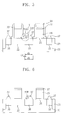
Referring to FIG. 1, a semiconductor substrate 21 having a front side 21F and a back side 21B may be provided. An isolation layer 23 defining an active region 22 may be formed in the semiconductor substrate 21. A gate electrode 26 and a gate dielectric layer 25 may be formed on the semiconductor substrate 21. The gate electrode 26 and the gate dielectric layer 25 may cross the active region 22. A buffer oxide layer 27 and a mask nitride layer 28 may be on the gate electrode 26.
The semiconductor substrate 21 may be a silicon (Si) wafer having impurity ions of a first conductivity type. The first conductivity type may be an n- or p-type. In this case, the n-type impurity ions may include arsenic (As) or phosphorus (P), and the p-type impurity ions may include boron (B). In some embodiments, the semiconductor substrate 21 may be a silicon wafer having the n-type impurity ions. The front side 21F may be referred to as a main surface. The front side 21F and the back side 21B may be parallel to each other.
The isolation layer 23 may be formed using shallow trench isolation (STI). The isolation layer 23 may be an insulating layer such as a silicon oxide layer, a silicon nitride layer, a silicon oxynitride layer or a combination thereof. The gate dielectric layer 25 may be interposed between the gate electrode 26 and the semiconductor substrate 21. The gate dielectric layer 25 may be formed of a silicon oxide layer, a silicon nitride layer, a silicon oxynitride layer, a high-K dielectric layer, or a combination thereof. The gate electrode 26 may be formed of a polysilicon layer.
The buffer oxide layer 27 and the mask nitride layer 28 may constitute a hard mask pattern. The hard mask pattern may be on the gate electrode 26. The buffer oxide layer 27 may be formed of a silicon oxide layer. The mask nitride layer 28 may be formed of a silicon nitride layer. As shown in FIG. 1, a plurality of spaced-apart gate electrodes 26 may be formed parallel to each other on the semiconductor substrate 21.
Referring to FIG. 2, a first sacrificial spacer 33 and a second sacrificial spacer 34 covering a sidewall of the gate electrode 26 may be formed. The active region 22 may be divided into a first region 22A and a second region 22B. The first and second regions 22A and 22B may be adjacent each other. The gate electrode 26 and the first and second sacrificial spacers 33 and 34 may cover the second region 22B. The first region 22A, on the other hand, may be exposed.
The first and second sacrificial spacers 33 and 34 may be formed of material layers having different etch selectivities. In some embodiments, the first sacrificial spacer 33 may be formed of a silicon nitride layer, and the second sacrificial spacer 34 may be formed of a silicon oxide layer. The first sacrificial spacer 33 may cover a sidewall of the gate electrode 26 and may cover the second region 22B. In this case, the first sacrificial spacer 33 may be formed in an “L” shape. For example, the first sacrificial spacer 33 may cover portions of the second region 22B between the gate electrode 26 and the first region 22A. The second sacrificial spacer 34 may cover an external sidewall of the first sacrificial spacer 33. A bottom of the second sacrificial spacer 34 may be in contact with the first sacrificial spacer 33. For example, the bottom of the second sacrificial spacer 34 may be in contact with a portion of the first sacrificial spacer 33 that extends from the external sidewall of the first sacrificial spacer 33.
Referring to FIG. 3, a trench 35T may be formed in the semiconductor substrate 21 using the first and second sacrificial spacers 33 and 34, the gate electrode 26, the buffer oxide layer 27, and the mask nitride layer 28 as etch masks.
The trench 35T may be formed using anisotropic etching. The trench 35T may be formed in various shapes having an upper portion narrower or wider than a lower portion. However, the upper and lower portions of the trench 35T may also have substantially the same width as each other.
Subsequently, the semiconductor substrate 21 having the trench 35T may be pre-cleaned. The pre-cleaning may be performed by a wet cleaning process. The second sacrificial spacer 34 may be removed by the pre-cleaning, and the first sacrificial spacer 33 may be conserved on the second region 22B.
Referring to FIG. 4, the semiconductor substrate 21 having the trench 35T may be put into an epitaxial process chamber for pre-baking. The pre-baking may be performed in germane (GeH4) and hydrogen chloride (HCl) atmosphere.
Subsequently, a recessed source and drain 35 filling the trench 35T may be formed using selective epitaxial growth (SEG). The recessed source and drain 35 may be formed of a semiconductor layer including impurity ions of a second conductivity type different from the first conductivity type. When the first conductivity type is an n-type, the second conductivity type may be a p-type, or vice versa. For example, the n-type impurity ions may include As and P, and the p-type impurity ions may include B. In some embodiments, the semiconductor substrate 21 may be a silicon wafer having the n-type impurity ions, and the recessed source and drain 35 may be a semiconductor layer having the p-type impurity ions.
The recessed source and drain 35 may be formed by supplying a silicon source gas, diborane (B2H6), GeH4, hydrogen (H2), and HCl to the epitaxial process chamber. The silicon source gas may be silicon tetrahydride/silane (SiH4). The recessed source and drain 35 may be formed to be a silicon germanium (SiGe) layer including B. Upper surfaces of the recessed source and drain 35 may be formed at a lower or higher level than the main surface/front side 21F. Alternatively, the upper surfaces of the recessed source and drain 35 may be formed at substantially the same level as the main surface/front side 21F. In other words, the upper surfaces of the recessed source and drain 35 may be substantially coplanar with the main surface/front side 21F.
Referring to FIG. 5, a capping layer 37 may be formed on the recessed source and drain 35 using SEG. The capping layer 37 may include a faceted sidewall 37F. The capping layer 37 may be formed of a semiconductor layer including the second conductivity type impurity ions. The capping layer 37 may be referred to as a faceted semiconductor pattern.
The recessed source and drain 35 may have a first width d1, the capping layer 37 may have a second width d2, and a third width d3 may be formed between the capping layer 37 and the first sacrificial spacer 33. The faceted sidewall 37F may form an angle of intersection (θ) of about 50 to about 59 degrees with the main surface/front side 21F of the semiconductor substrate 21. In some embodiments, the faceted sidewall 37F may form an angle of intersection (θ) of about 51 to about 55 degrees with the main surface/front side 21F of the semiconductor substrate 21.
As a result, the faceted sidewall 37F may be separated from the first sacrificial spacer 33. In addition, the second width d2 may be smaller than the first width d1. Further, the capping layer 37 may be spaced the third width d3 apart from the first sacrificial spacer 33. The capping layer 37 may be formed to have a thickness of 5 to 100 nanometers (nm).
FIGS. 10 through 15 illustrate methods of forming the recessed source and drain 35 and the capping layer 37.
Referring to FIG. 10, a method of forming a semiconductor device according to some embodiments may include formation of a trench 35T (Block S1), pre-cleaning (Block S2), pre-baking (Block S3), formation of a source and a drain (Block S4), purging (Block S5), and a cyclic SEG process 100. The cyclic SEG process 100 may include formation of a capping layer 37 (Block S6), purging (Block S7), etching (Block S8), purging (Block S9), and thickness measurement (Block S10). The pre-baking (Block S3) through the cyclic SEG process 100 may be in-situ processes, which are continuously performed in the same chamber. That is, after the semiconductor substrate 21 is put into the epitaxial process chamber, the pre-baking (Block S3) through the cyclic SEG process 100 may be continuously performed. The cyclic SEG process 100 may be performed once or more to control the thickness of the capping layer 37 and the angle of intersection (θ) of the faceted sidewall 37F.
The formation of the trench 35T (Block S1) and the pre-cleaning (Block S2) may be similar to those described with reference to FIG. 3. The pre-baking (Block S3), the formation of the source and drain (Block S4), and the purging (Block S5) may be similar to those described with reference to FIG. 4. The source and drain may correspond to the recessed source and drain 35. In other words, in some embodiments, the source and drain may be SiGe layers including B. The purging (Block S5) may be performed by supplying H2 to the epitaxial process chamber.
Referring to FIGS. 10 and 12, the cyclic SEG process 100 may include the formation of the capping layer 37 (Block S6) and the purging (Block S7).
Specifically, in Block S6, the capping layer 37 may be formed by supplying a silicon source gas, B2H6, GeH4, H2, and HCl to the epitaxial process chamber. The silicon source gas may be SiH4. In Block S6, the capping layer 37 may be performed in the epitaxial process chamber under an inner temperature of 700 to 900° C. As a result, a first capping layer 37A may be selectively grown on the recessed source and drain 35. The first capping layer 37A may be a single crystalline Si layer including B. The purging (Block S7) may be performed by supplying H2 to the epitaxial process chamber.
Referring to FIGS. 10 and 13, the etching (Block S8) may be performed by supplying H2 and HCl to the epitaxial process chamber. The purging (Block S9) may be performed by supplying H2 to the epitaxial process chamber. As a result, the first capping layer 37A may be partially etched to form a second capping layer 37B. Accordingly, the second capping layer 37B may be separated from the first sacrificial spacer 33.
Afterward, the thickness of the second capping layer 37B may be measured (Block S10).
Referring to FIGS. 10 and 14, a third capping layer 37C and a fourth capping layer 37D may be formed by repeating the cyclic SEG process 100. For example, the cyclic SEG process 100 may be repeated in response to a comparison of a measured thickness of the second capping layer 37B with a threshold thickness. The fourth capping layer 37D may be formed by portions of the third capping layer 37C remaining on the second capping layer 37B after the etching (Block S8). The fourth capping layer 37D may be separated from the first sacrificial spacer 33.
Referring to FIGS. 10 and 15, a fifth capping layer 37E may be formed on the fourth capping layer 37D by repeating the cyclic SEG process 100 again. The fifth capping layer 37E may be separated from the first sacrificial spacer 33. The second capping layer 37B, the fourth capping layer 37D and the fifth capping layer 37E may constitute the capping layer 37. The capping layer 37 may include the faceted sidewall 37F. A gap 37G may be formed between the capping layer 37 and the first sacrificial spacer 33.
The semiconductor substrate 21 may define the front side 21F of FIG. 1 and the back side 21B of FIG. 1. An extension of the front side 21F may be referred to as the main surface. The faceted sidewall 37F may be formed to an angle of intersection (θ) of 51 to 55 degrees with the main surface. For example, the faceted sidewall 37F may be formed to an angle of intersection (θ) of approximately 53 degrees. The angle (θ) of the faceted sidewall 37F may be controlled by the number of iterations of the cyclic SEG process 100.
The capping layer 37 may be a single crystalline Si layer including B. In some other embodiments, the capping layer 37 may be a silicon carbide (SiC) or SiGe layer. An upper surface of the capping layer 37 may be formed at a higher level than the gate dielectric/insulating layer 25.
Referring to FIG. 11, the method of forming a semiconductor device according to some embodiments may include formation of a trench 35T (Block Si), pre-cleaning (Block S2), pre-baking (Block S3), formation of a source and a drain (Block S4), purging (Block S5), formation of a capping layer 37 (Block S6′) and purging (Block S7′). The pre-baking (Block S3) through the purging (Block S7′) may be in-situ processes which are continuously performed in the same chamber. That is, after the semiconductor substrate 21 is put into the epitaxial process chamber, the pre-baking (Block S3) through the purging (Block S7′) may be continuously performed.
The formation of the trench 35T (Block S1) through the purging (Block S5) may be substantially the same as those described with reference to FIG. 10. The capping layer 37 (Block S6′) may be formed by supplying a silicon source gas, B2H6, GeH4, H2, and HCl to the epitaxial process chamber. The silicon source gas may be SiH4. As a result, the capping layer 37 may be selectively grown on the recessed source and drain 35. The capping layer 37 may be a single-crystalline Si layer including B. The purging (Block S7′) may be performed by supplying H2 to the epitaxial process chamber. The capping layer 37 may include the faceted sidewall 37F. A gap 37G may be formed between the capping layer 37 and the first sacrificial spacer 33. The faceted sidewall 37F may be formed to an angle of intersection (θ) of approximately 58 degrees with the main surface.
Referring to FIG. 6, the first sacrificial spacer 33 may be removed to expose the active region 22 between the gate electrode 26 and the capping layer 37. To remove the first sacrificial spacer 33, an etching process using phosphoric acid (H3PO4) may be applied. During the removal of the first sacrificial spacer 33, the mask nitride layer 28 may be also removed. The buffer oxide layer 27 may be conserved on the gate electrode 26. In some embodiments, the buffer oxide layer 27 may be also removed.
Referring to FIG. 7, a first spacer 41 covering a sidewall of the gate electrode 26 may be formed. The first spacer 41 may be referred to as an offset spacer. The active region 22 may be exposed between the first spacer 41 and the capping layer 37. That is, the first spacer 41 may be formed to be separated from the capping layer 37. A lightly doped drain (LDD) 43 and a “halo” region 45 may be formed in the active region 22.
The first spacer 41 may be formed of an insulating layer such as a silicon oxide layer, a silicon nitride layer, a silicon oxynitride layer, or a combination thereof. The LDD 43 may be formed by implanting the second conductivity type impurity ions into the active region 22 using the first spacer 41 and the gate electrode 26 as ion implantation masks. The halo 45 may be formed by implanting the first conductivity type impurity ions into the active region 22 using the first spacer 41 and the gate electrode 26 as ion implantation masks.
The LDD 43 and the halo 45 may be formed by an inclined ion implantation process using ion implantation energy at various inclinations selected based on the angle (θ) of the faceted sidewall 37F of the capping layer 37. The LDD 43 and the halo 45 may be aligned between the first spacer 41 and the capping layer 37. The halo 45 may be formed at a lower level than the LDD 43. In other words, the LDD 43 may be between the halo 45 and the first spacer 41. In some embodiments, the LDD 43 and/or the halo 45 may be formed before the first spacer 41. The LDD 43 and/or the halo 45 may be aligned between the gate electrode 26 and the capping layer 37.
In some embodiments, due to the angle (θ) of the faceted sidewall 37F, a sufficient margin may be provided to form the LDD 43 and/or the halo 45 between the first spacer 41 and the capping layer 37.
Referring to FIG. 8, a second spacer 47 covering an external sidewall of the first spacer 41 may be formed. A high concentration impurity region 35 p may be formed by implanting the second conductivity type impurity ions into the semiconductor substrate 21 using the first spacer 41, the second spacer 47, and the gate electrode 26 as ion implantation masks. The LDD 43 and the halo 45 may be conserved or maintained under the first spacer 41 and the second spacer 47.
The second spacer 47 may be formed of an insulating layer such as a silicon oxide layer, a silicon nitride layer, a silicon oxynitride layer, or a combination thereof. The high concentration impurity region 35 p may be formed in the capping layer 37 and the recessed source and drain 35. For example, the high concentration impurity region 35 p may be formed to have substantially the same width as the capping layer 37 and the recessed source and drain 35, and the high concentration impurity region 35 p may be formed at a higher level than bottom surfaces of the recessed source and drain 35.
In other embodiments, the high concentration impurity region 35 p may be formed to have substantially the same depth and width as the capping layer 37 and the recessed source and drain 35, or may be formed to have higher width and depth than the capping layer 37 and the recessed source and drain 35.
Referring to FIG. 9, the buffer oxide layer 27 may be removed to expose the gate electrode 26. A gate metal silicide layer 26S and a drain metal silicide layer 37S may be formed on the gate electrode 26 and the capping layer 37, respectively. The gate metal silicide layer 26S and the drain metal silicide layer 37S may be formed of nickel silicide (NiSi), cobalt silicide (CoSi), titanium silicide (TiSi), or tantalum silicide (TaSi). The drain metal silicide layer 37S may be formed along a surface of the capping layer 37.
In some embodiments, the capping layer 37 may be entirely converted into the drain metal silicide layer 37S. Further, a partial region of the recessed source and drain 35 may be also converted into the drain metal silicide layer 37S.
FIGS. 16 through 20 are cross-sectional views illustrating a method of forming a semiconductor device according to some embodiments.
Referring to FIG. 16, an isolation layer 23 defining an active region 22 may be formed in a semiconductor layer 21. A gate electrode 26 and a gate dielectric layer 25 may be formed on the semiconductor layer 21. The gate electrode 26 and the gate dielectric layer 25 may cross the active region 22. A buffer oxide layer 27 and a mask nitride layer 28 may be on the gate electrode 26.
A sacrificial spacer 133 covering a sidewall of the gate electrode 26 may be formed. The active region 22 may be divided into a first region 22A and a second region 22B. The gate electrode 26 and the sacrificial spacer 133 may cover the second region 22B. The sacrificial spacer 133 may be formed of a silicon nitride layer.
A trench 135T may be formed in the semiconductor substrate 21 using the sacrificial spacer 133, the gate electrode 26, the buffer oxide layer 27, and the mask nitride layer 28 as etch masks. Subsequently, the semiconductor substrate 21 having the trench 135T may be pre-cleaned. The pre-cleaning may be performed by a wet cleaning process. The sacrificial spacer 133 may be conserved on the second region 22B.
Referring to FIG. 17, the semiconductor substrate 21 having the trench 135T may be put into an epitaxial process chamber for pre-baking. The pre-baking may be performed in GeH4 and HCl atmosphere.
Subsequently, a recessed source and drain 135 filling the trench 135T may be formed using SEG. The recessed source and drain 135 may be formed of a semiconductor layer including impurity ions of a second conductivity type which is different from the first conductivity type. The second conductivity type may be an n- or p-type. In some embodiments, the semiconductor substrate 21 may be a silicon wafer having the n-type impurity ions, and the recessed source and drain 135 may be semiconductor layers having the p-type impurity ions.
The recessed source and drain 135 may be formed by supplying a silicon source gas, B2H6, GeH4, H2, and HCl to the epitaxial process chamber. The silicon source gas may be SiH4. For example, the recessed source and drain 135 may be a SiGe layer including B. As illustrated in FIG. 17, an upper surface of the recessed source and drain 135 may be formed at a higher level than the main surface of the semiconductor substrate 21.
Afterward, a capping layer 137 may be formed on the recessed source and drain 135 using SEG. The capping layer 137 may be formed by a method similar to that described with reference to FIGS. 10 through 15. The capping layer 137 may include a faceted sidewall 137F. The capping layer 137 may be formed of a semiconductor layer including second conductivity type impurity ions. The capping layer 137 may be referred to as a faceted semiconductor pattern.
The recessed source and drain 135 may have a first width d1, and the capping layer 137 may have a second width d2. A third width d3 may be formed between the capping layer 137 and the sacrificial spacer 133. The faceted sidewall 137F may be formed to an angle of intersection (θ) of about 50 to about 59 degrees with the main surface of the semiconductor substrate 21. In some embodiments, the faceted sidewall 137F may be formed to an angle of intersection (θ) of about 51 to about 55 degrees with the main surface of the semiconductor substrate 21.
As a result, the faceted sidewall 137F may be separated from the sacrificial spacer 133. That is, a gap 137G may be formed between the capping layer 137 and the sacrificial spacer 133. In addition, the second width d2 may be smaller than the first width d1. Furthermore, the capping layer 137 may be formed to be spaced the third width d3 apart from the sacrificial spacer 133. The capping layer 137 may be formed to have a thickness of about 5 to 100 nm.
Referring to FIG. 18, the sacrificial spacer 133 may be removed to expose the active region 22 between the gate electrode 26 and the capping layer 137. A first spacer 141 covering a sidewall of the gate electrode 26 may be formed. An LDD 143 and a halo 145 may be formed in the active region 22 using inclined ion implantation.
The LDD 143 may be formed by implanting the second conductivity type impurity ions into the active region 22 using the first spacer 141 and the gate electrode 26 as ion implantation masks. The halo 145 may be formed by implanting the first conductivity type impurity ions into the active region 22 using the first spacer 141 and the gate electrode 26 as ion implantation masks.
According to some embodiments, a sufficient margin may be provided to form the LDD 143 and/or the halo 145 between the first spacer 141 and the capping layer 137 due to the angle (θ) of the faceted sidewall 137F.
Referring to FIG. 19, a second spacer 147 covering an external sidewall of the first spacer 141 may be formed. A high concentration impurity region may be formed by implanting the second conductivity type impurity ions into the semiconductor substrate 21 using the first spacer 141, the second spacer 147, and the gate electrode 26 as ion implantation masks. The high concentration impurity region may be formed to have substantially the same depth and width as the capping layer 137 and the recessed source and drain 135. The LDD 143 and the halo 145 may be conserved under the first spacer 141 and the second spacer 147.
Referring to FIG. 20, the buffer oxide layer 27 may be removed to expose the gate electrode 26. A gate metal silicide layer 26S and a drain metal silicide layer 137S may be formed on the gate electrode 26 and the capping layer 137, respectively. The drain metal silicide layer 137S may be formed along a surface of the capping layer 37.
FIGS. 21 through 24 are cross-sectional views illustrating a method of forming a semiconductor device according to some embodiments.
Referring to FIG. 21, a semiconductor substrate 21 having a front side 21F and a back side 21B may be provided. An isolation layer 23 defining an active region 22 may be formed in the semiconductor substrate/layer 21. A gate electrode 26 and a gate dielectric layer 25 may be formed on the semiconductor substrate 21. The gate electrode 26 and the gate dielectric layer 25 may cross the active region 22. A buffer oxide layer 27 and a mask nitride layer 28 may be on the gate electrode 26. A sacrificial spacer 133 covering a sidewall of the gate electrode 26 may be formed. The active region 22 may be divided into a first region 22A and a second region 22B. The gate electrode 26 and the sacrificial spacer 133 may cover the second region 22B.
The semiconductor substrate 21 may be a silicon wafer having impurity ions of a first conductivity type. The first conductivity type may be an n- or p-type. The n-type impurity ions may include As and P, and the p-type impurity ions may include B. The front side 21F may be referred to as a main surface. The front side 21F and the back side 21B may be parallel to each other.
A capping layer 237 may be formed in the first region 22A using SEG. The capping layer 237 maybe formed by a method similar to that described with reference to FIGS. 10 through 15. The capping layer 237 may include a faceted sidewall 237F. The capping layer 237 may be formed of a semiconductor layer including impurity ions of a second conductivity type which is different from the first conductivity type. The capping layer 237 may be referred to as a faceted semiconductor pattern. When the first conductivity type is an n-type, the second conductivity type may be a p-type, or vice versa. In some embodiments, the capping layer 237 may be a single-crystalline Si layer including B.
The first region 22A may include a first width d1, and the capping layer 237 may include a second width d2. A third width d3 may be formed between the capping layer 237 and the sacrificial spacer 133. The faceted sidewall 237F may be formed to an angle of intersection (θ) of about 50 to about 59 degrees with the main surface of the semiconductor substrate 21. In some embodiments, the faceted sidewall 237F may be formed to an angle of intersection (θ) of about 51 to about 55 degrees with the main surface the semiconductor substrate 21.
As a result, the faceted sidewall 237F may be separated from the sacrificial spacer 133. That is, a gap 237G may be formed between the capping layer 237 and the sacrificial spacer 133. In addition, the second width d2 may be smaller than the first width d1. Furthermore, the capping layer 237 may be formed to be spaced the third width d3 apart from the sacrificial spacer 133. The capping layer 237 may be formed to have a thickness of 5 to 100 nm.
Referring to FIG. 22, the sacrificial spacer 133 may be removed to expose the active region 22 between the gate electrode 26 and the capping layer 237. A first spacer 241 covering a sidewall of the gate electrode 26 may be formed. An LDD 243 and a halo 245 may be formed in the active region 22 using inclined ion implantation.
The LDD 243 may be formed by implanting the second conductivity type impurity ions into the active region 22 using the first spacer 241 and the gate electrode 26 as ion implantation masks. The halo 245 may be formed by implanting the first conductivity type impurity ions into the active region 22 using the first spacer 241 and the gate electrode 26 as ion implantation masks.
According to some embodiments, a sufficient margin may be provided to form the LDD 243 and/or the halo 245 between the first spacer 241 and the capping layer 237 due to the angle (θ) of the faceted sidewall 237F.
Referring to FIG. 23, a second spacer 247 covering an external sidewall of the first spacer 241 may be formed. A high concentration impurity region may be formed by implanting the second conductivity type impurity ions into the semiconductor substrate 21 using the first spacer 241, the second spacer 247, and the gate electrode 26 as ion implantation masks. The LDD 243 and the halo 245 may be conserved under the first spacer 241 and the second spacer 247.
Referring to FIG. 24, the buffer oxide layer 27 may be removed to expose the gate electrode 26. A gate metal silicide layer 26S and a drain metal silicide layer 237S may be formed on the gate electrode 26 and the capping layer 237, respectively. The drain metal silicide layer 237S may be formed along a surface of the capping layer 237.
FIGS. 25 and 26 are cross-sectional views illustrating a method of forming a semiconductor device according to some embodiments.
Referring to FIG. 25, an isolation layer 23 defining an active region 22 may be formed in a semiconductor layer 21. A gate electrode 26 and a gate dielectric layer 25 which cross the active region 22 may be formed. A buffer oxide layer 27 and a mask nitride layer 28 may remain on the gate electrode 26. The semiconductor substrate 21 may be a silicon wafer having impurity ions of a first conductivity type.
A first sacrificial spacer 33 and a second sacrificial spacer 34 covering a sidewall of the gate electrode 26 may be formed. A high concentration impurity region 35A may be formed by implanting impurity ions of a second conductivity type into the semiconductor substrate 21 using the first and second sacrificial spacers 33 and 34, the gate electrode 26, the buffer oxide layer 27, and the mask nitride layer 28 as ion implantation masks.
A trench 35T may be formed in the semiconductor substrate 21 using the first and second sacrificial spacers 33 and 34, the gate electrode 26, the buffer oxide layer 27, and the mask nitride layer 28 as etch masks. The high concentration impurity region 35A may be conserved on a bottom and sidewalls of the trench 35T.
Subsequently, the semiconductor substrate 21 having the trench 35T may be pre-cleaned. The pre-cleaning may be performed by a wet cleaning process. The second sacrificial spacer 34 may be removed by the pre-cleaning, and the first sacrificial spacer 33 may be conserved on the active region 22.
Referring to FIG. 26, the semiconductor substrate 21 having the trench 35T may be put into an epitaxial process chamber for pre-baking. The pre-baking may be performed in GeH4 and HCl atmosphere. Subsequently, recessed source and drain 35, a capping layer 37, a first spacer 41, an LDD 43, a halo 45, a second spacer 47, a gate metal silicide layer 26S, and a drain metal silicide layer 37S may be formed by a method similar to that described with reference to FIGS. 4 through 15.
FIG. 27 is a diagram of an electronic system according to some embodiments,
Referring to FIG. 27, an electronic system 1100 according to some embodiments may include a controller 1110, an input/output device 1120, a memory device 1130, an interface 1140, and a bus architecture 1150. The memory device 1130 and/or the controller 1110 may include a semiconductor device similar to those described with reference to FIGS. 1 through 26. The bus architecture 1150 may serve to provide a path through which data between the controller 1110, the input/output device 1120, the memory device 1130, and the interface 1140 are moved.
The controller 1110 may include at least one microprocessor, a digital signal processor, a microcontroller, and at least one of logic devices capable of performing similar functions thereto. The input/output device 1120 may include at least one of a key pad, a keyboard, and a display device. The memory device 1130 may serve to store data and/or commands executed by the controller 1110.
The memory device 1130 may be a volatile memory chip such as a dynamic random access memory (DRAM) or static random access memory (SRAM), a non-volatile memory chip such as a flash memory, a phase change memory, a magnetic random access memory (MRAM), or a resistive random access memory (RRAM), or a combination thereof. For example, the electronic system 1100 may be a solid state disk (SSD).
The interface 1140 may serve to transmit or receive data to or from a communication network. The interface 1140 may be a wired/wireless type. For example, the interface 1140 may include an antenna or a wired/wireless transceiver. The electronic system 1100 may further include an application chipset, a camera image processor (CIS), and an input/output device.
The electronic system 1100 may be realized as a mobile system, a personal computer, an industrial computer, and/or a logic system performing various functions. For example, a mobile system may be one of a personal digital assistant (PDA), a portable computer, a web tablet, a mobile phone, a wireless phone, a laptop computer, a memory card, a digital music system, and a data transceiver system. When the electronic system 1100 is an apparatus capable of performing wireless communication, it may be used in a communication system such as code division multiple access (CDMA), global system for mobile communication (GSM), North American digital cellular (NADC), enhanced-time division multiple access (E-TDMA), wideband code division multiple access (WCDMA), or CDMA2000.
According to some embodiments, a capping layer having a faceted sidewall is provided on recessed source and drain. The faceted sidewall may be formed at an angle selected to provide a sufficient margin to form an LDD and/or a halo. As a result, a semiconductor device having excellent electrical characteristics can be realized.
The above-disclosed subject matter is to be considered illustrative and not restrictive, and the appended claims are intended to cover all such modifications, enhancements, and other embodiments, which fall within the true spirit and scope of the disclosure. Thus, to the maximum extent allowed by law, the scope of the disclosure is to be determined by the broadest permissible interpretation of the following claims and their equivalents, and shall not be restricted or limited by the foregoing detailed description.

Claims (19)

What is claimed is:
1. A method of forming a semiconductor device, comprising:
preparing a semiconductor substrate including a first region and a second region adjacent the first region;
forming a sacrificial pattern covering the second region and exposing the first region;
forming a capping layer including a faceted sidewall on the exposed first region using selective epitaxial growth (SEG), the faceted sidewall being separated from the sacrificial pattern;
removing the sacrificial pattern; and
implanting impurity ions into the semiconductor substrate using an inclined ion implantation process,
wherein the faceted sidewall is formed to an angle of intersection of about 50 to about 59 degrees with a main surface of the semiconductor substrate that is substantially coplanar with a surface of the sacrificial pattern, and
wherein implanting impurity ions comprises forming a lightly doped drain (LDD) and a halo in the second region using the inclined ion implantation process at inclinations selected based on the angle of intersection of the faceted sidewall.
2. The method of claim 1, wherein the angle of intersection comprises about 51 to about 55 degrees.
3. The method of claim 1, wherein forming the capping layer comprises performing a cyclic SEG process at least once, the cyclic SEG process including:
supplying a silicon source gas, diborane (B2H6), hydrogen (H2) and hydrogen chloride (HCl) to the semiconductor substrate and forming a semiconductor layer;
supplying H2 to the semiconductor substrate having the semiconductor layer for purging; and
supplying a selective etching gas including H2 and HCl to the semiconductor substrate having the semiconductor layer,
wherein a number of iterations of the cyclic SEG process is selected to form the faceted sidewall at a desired angle of intersection with a main surface of the semiconductor substrate that is substantially coplanar with a surface of the sacrificial pattern.
4. The method of claim 3, wherein the cyclic SEG process is repeated in response to a comparison of a thickness of a sub-layer of the capping layer with a threshold thickness.
5. The method of claim 1, wherein forming the capping layer comprises supplying a silicon source gas, diborane (B2H6), hydrogen (H2), and hydrogen chloride (HCl) to the semiconductor substrate.
6. The method of claim 1, wherein the capping layer is separated from the sacrificial pattern.
7. A method of forming a semiconductor device, comprising:
forming a gate electrode on a semiconductor substrate;
forming a sacrificial spacer covering a sidewall of the gate electrode;
forming a trench in the semiconductor substrate adjacent the gate electrode and the sacrificial spacer;
forming a recessed source and drain filling the trench;
forming a capping layer having a faceted sidewall on the recessed source and drain using selective epitaxial growth (SEG), the faceted sidewall being separated from the sacrificial spacer and being between sidewalls of the recessed source and drain;
removing the sacrificial spacer; and
implanting impurity ions into the semiconductor substrate,
wherein the faceted sidewall is formed to an angle of intersection of about 50 to about 59 degrees with a main surface of the semiconductor substrate that is substantially coplanar with a surface of the sacrificial spacer, and
wherein implanting impurity ions comprises forming a lightly doped drain (LDD) and a halo using an inclined ion implantation process at inclinations selected based on the angle of intersection of the faceted sidewall.
8. The method of claim 7, wherein a surface of the recessed source and drain is formed to extend farther from the semiconductor substrate than a surface of the sacrificial spacer that opposes the semiconductor substrate.
9. The method of claim 7, wherein the recessed source and drain include silicon germanium (SiGe) layers including boron (B).
10. The method of claim 7, wherein the capping layer includes a single crystalline silicon (Si) layer including boron (B).
11. The method of claim 7, wherein forming the capping layer comprises performing a cyclic SEG process at least once, the cyclic SEG process including:
supplying a silicon source gas, diborane (B2H6), hydrogen (H2), and hydrogen chloride (HCl) to the semiconductor substrate and forming a semiconductor layer;
supplying H2 to the semiconductor substrate having the semiconductor layer for purging; and
supplying a selective etching gas including H2 and HCl to the semiconductor substrate having the semiconductor layer.
12. The method of claim 7, wherein a surface of the recessed source and drain is formed to be substantially coplanar with a surface of the sacrificial spacer.
13. The method of claim 7, wherein the semiconductor substrate includes impurity ions of a first conductivity type and a second conductivity type, and wherein implanting the impurity ions into the semiconductor substrate comprises:
implanting the ions of the second conductivity type to form a lightly doped drain (LDD) in the semiconductor substrate using the gate electrode as an ion implantation mask; and
implanting the ions of the first conductivity type to form a halo in the semiconductor substrate using the gate electrode as an ion implantation mask.
14. The method of claim 13, further comprising: before forming the trench, implanting the ions of the second conductivity type to form a high concentration impurity region.
15. The method of claim 7, further comprising forming a metal silicide layer on the capping layer.
16. The method of claim 7, wherein the capping layer has a smaller width than the recessed source and drain, and wherein the width of the capping layer is along a direction that is substantially parallel to a surface of the semiconductor substrate.
17. The method of claim 7, wherein the sacrificial spacer is formed in an “L” shape.
18. A method of forming a semiconductor device, comprising:
forming a gate electrode on a semiconductor substrate of a first conductivity type;
forming a sacrificial spacer on a sidewall of the gate electrode;
forming a trench in the semiconductor substrate adjacent the sacrificial spacer by using the sacrificial spacer as an etch mask;
forming a semiconductor layer filling the trench, the semiconductor layer comprising a second conductivity type;
forming a capping layer including a diagonal sidewall on the semiconductor layer using selective epitaxial growth (SEG), the diagonal sidewall being spaced apart from the sacrificial spacer, wherein the diagonal sidewall is formed to an angle of intersection of about 50 to about 59 degrees with a main surface of the semiconductor substrate that is substantially coplanar with a surface of the sacrificial spacer;
removing the sacrificial spacer;
implanting ions of the second conductivity type into the semiconductor substrate using the gate electrode as an ion implantation mask to form a lightly doped drain (LDD) region on a sidewall of the semiconductor layer, using an inclined ion implantation process at inclinations selected based on the angle of intersection of the diagonal sidewall; and
implanting ions of the first conductivity type into the semiconductor substrate using the gate electrode as an ion implantation mask to form a halo region on the sidewall of the semiconductor layer and between the gate electrode and the capping layer, using the inclined ion implantation process at the inclinations selected based on the angle of intersection of the diagonal sidewall.
19. The method of claim 18, further comprising: forming an offset spacer on a sidewall of the gate electrode before forming the LDD and the halo, wherein the offset spacer is spaced apart from the capping layer.
US13/052,460 2010-03-19 2011-03-21 Methods of forming semiconductor devices having faceted semiconductor patterns Active 2032-05-17 US8703592B2 (en)

Applications Claiming Priority (3)

Application Number Priority Date Filing Date Title
JP10-2010-0024789 2010-03-19
KR1020100024789A KR101714003B1 (en) 2010-03-19 2010-03-19 Method of forming semiconductor device having faceted semiconductor pattern and related device
KR10-2010-0024789 2010-03-19

Publications (2)

Publication Number Publication Date
US20110230027A1 US20110230027A1 (en) 2011-09-22
US8703592B2 true US8703592B2 (en) 2014-04-22

Family

ID=44650532

Family Applications (1)

Application Number Title Priority Date Filing Date
US13/052,460 Active 2032-05-17 US8703592B2 (en) 2010-03-19 2011-03-21 Methods of forming semiconductor devices having faceted semiconductor patterns

Country Status (2)

Country Link
US (1) US8703592B2 (en)
KR (1) KR101714003B1 (en)

Cited By (1)

* Cited by examiner, † Cited by third party
Publication number Priority date Publication date Assignee Title
US9299839B2 (en) * 2014-09-01 2016-03-29 United Microelectronics Corporation PFET and CMOS containing same

Families Citing this family (16)

* Cited by examiner, † Cited by third party
Publication number Priority date Publication date Assignee Title
US8816409B2 (en) * 2010-07-15 2014-08-26 United Microelectronics Corp. Metal-oxide semiconductor transistor
KR101776926B1 (en) * 2010-09-07 2017-09-08 삼성전자주식회사 Semiconductor device and method for manufacturing the same
US9847225B2 (en) * 2011-11-15 2017-12-19 Taiwan Semiconductor Manufacturing Company, Ltd. Semiconductor device and method of manufacturing the same
US8962433B2 (en) 2012-06-12 2015-02-24 United Microelectronics Corp. MOS transistor process
CN104183491B (en) * 2013-05-21 2018-05-01 中芯国际集成电路制造(上海)有限公司 The forming method of transistor
CN104681441A (en) * 2013-11-29 2015-06-03 中芯国际集成电路制造(上海)有限公司 Method for preventing embedded germanium silicon top cap layer from etching pollution
CN104752216B (en) * 2013-12-30 2017-11-03 中芯国际集成电路制造(上海)有限公司 The forming method of transistor
US9343412B2 (en) * 2014-02-12 2016-05-17 Taiwan Semiconductor Manufacturing Company Limited Method of forming MOSFET structure
JP6275559B2 (en) * 2014-06-13 2018-02-07 ルネサスエレクトロニクス株式会社 Semiconductor device and manufacturing method thereof
US9490340B2 (en) 2014-06-18 2016-11-08 Globalfoundries Inc. Methods of forming nanowire devices with doped extension regions and the resulting devices
US9431512B2 (en) * 2014-06-18 2016-08-30 Globalfoundries Inc. Methods of forming nanowire devices with spacers and the resulting devices
KR102171023B1 (en) * 2014-07-21 2020-10-29 삼성전자주식회사 Method of fabricating semiconductor devices
US9871042B2 (en) * 2015-12-03 2018-01-16 Samsung Electronics Co., Ltd. Semiconductor device having fin-type patterns
CN107180764B (en) * 2016-03-11 2020-09-04 中芯国际集成电路制造(上海)有限公司 Semiconductor device, manufacturing method thereof and electronic device
CN107437504B (en) * 2016-05-26 2020-06-09 中芯国际集成电路制造(上海)有限公司 Semiconductor device, manufacturing method thereof and electronic device
WO2018063335A1 (en) * 2016-09-30 2018-04-05 Intel Corporation Tunneling transistors including source/drain regions employing carbon-based etch stop layer

Citations (57)

* Cited by examiner, † Cited by third party
Publication number Priority date Publication date Assignee Title
US4549926A (en) 1982-01-12 1985-10-29 Rca Corporation Method for growing monocrystalline silicon on a mask layer
US4578142A (en) 1984-05-10 1986-03-25 Rca Corporation Method for growing monocrystalline silicon through mask layer
US4578143A (en) 1982-08-26 1986-03-25 Ushio Denki Kabushiki Kaisha Method for forming a single crystal silicon layer
US4592792A (en) 1985-01-23 1986-06-03 Rca Corporation Method for forming uniformly thick selective epitaxial silicon
JPS61265814A (en) 1985-05-20 1986-11-25 Nec Corp Manufacture of compound semiconductor device
US4698316A (en) 1985-01-23 1987-10-06 Rca Corporation Method of depositing uniformly thick selective epitaxial silicon
US4838993A (en) 1986-12-04 1989-06-13 Seiko Instruments Inc. Method of fabricating MOS field effect transistor
JPH0350191A (en) 1989-07-17 1991-03-04 Kawasaki Steel Corp Epitaxial growth method
JPH0350771A (en) 1989-07-18 1991-03-05 Seiko Instr Inc Semiconductor device
JPH07161991A (en) 1993-12-10 1995-06-23 Ricoh Co Ltd Manufacture of semiconductor device
US5635746A (en) 1995-07-06 1997-06-03 Mitsubishi Denki Kabushiki Kaisha Semiconductor device comprising a salicide structure
US5733792A (en) * 1995-07-28 1998-03-31 Nec Corporation MOS field effect transistor with improved pocket regions for suppressing any short channel effects and method for fabricating the same
US5739573A (en) 1994-07-22 1998-04-14 Nec Corporation Semiconductor device with improved salicide structure and a method of manufacturing the same
US5899752A (en) 1993-07-30 1999-05-04 Applied Materials, Inc. Method for in-situ cleaning of native oxide from silicon surfaces
KR20000032858A (en) 1998-11-18 2000-06-15 윤종용 Method for fabricating semiconductor device capable of assuring misalign margin
KR20000055596A (en) 1999-02-08 2000-09-15 윤종용 Method for forming gate electrode with polycide structure
US6190976B1 (en) * 1997-11-26 2001-02-20 Nec Corporation Fabrication method of semiconductor device using selective epitaxial growth
US6190453B1 (en) 1999-07-14 2001-02-20 Seh America, Inc. Growth of epitaxial semiconductor material with improved crystallographic properties
KR20010036270A (en) 1999-10-07 2001-05-07 윤종용 FET device having elevated source/drain and method for fabricating with partial facet control
US6290774B1 (en) 1999-05-07 2001-09-18 Cbl Technology, Inc. Sequential hydride vapor phase epitaxy
US6346732B1 (en) 1999-05-14 2002-02-12 Kabushiki Kaisha Toshiba Semiconductor device with oxide mediated epitaxial layer
KR20020013197A (en) 2000-08-11 2002-02-20 윤종용 Selective epitaxial growth method in semiconductor device
KR20020028488A (en) 2000-10-10 2002-04-17 박종섭 Method for growthing a epi-layer and a method for manufacturing a transistor using the same
US6429084B1 (en) 2001-06-20 2002-08-06 International Business Machines Corporation MOS transistors with raised sources and drains
US20020157688A1 (en) 2001-04-30 2002-10-31 Joo Sung Jae Method for cleaning a substrate in selective epitaxial growth process
US6489206B2 (en) * 2001-03-22 2002-12-03 United Microelectronics Corp. Method for forming self-aligned local-halo metal-oxide-semiconductor device
US20020192930A1 (en) 2001-06-02 2002-12-19 Hwa-Sung Rhee Method of forming a single crystalline silicon pattern utilizing a structural selective epitaxial growth technique and a selective silicon etching technique
US6605498B1 (en) 2002-03-29 2003-08-12 Intel Corporation Semiconductor transistor having a backfilled channel material
US20040045499A1 (en) 2002-06-10 2004-03-11 Amberwave Systems Corporation Source and drain elements
JP2004095639A (en) 2002-08-29 2004-03-25 Fujitsu Ltd Semiconductor device and its manufacturing method
US20040129982A1 (en) 2000-05-25 2004-07-08 Renesas Technology Corporation Semiconductor device and manufacturing method
US6777759B1 (en) 1997-06-30 2004-08-17 Intel Corporation Device structure and method for reducing silicide encroachment
US20040171238A1 (en) 2003-01-24 2004-09-02 Arena Chantal J. Enhanced selectivity for epitaxial deposition
KR20050010252A (en) 2003-07-18 2005-01-27 주식회사 하이닉스반도체 A method for forming a contact plug of a semiconductor device
US6852600B1 (en) 2002-10-29 2005-02-08 Advanced Micro Devices, Inc. Strained silicon MOSFET having silicon source/drain regions and method for its fabrication
US20050040472A1 (en) 2003-08-22 2005-02-24 Samsung Electronics Co., Ltd. Highly integrated semiconductor device with silicide layer that secures contact margin and method of manufacturing the same
JP2005228761A (en) 2004-02-10 2005-08-25 Rohm Co Ltd Semiconductor device and its manufacturing method
US20050263795A1 (en) 2004-05-25 2005-12-01 Jeong-Dong Choi Semiconductor device having a channel layer and method of manufacturing the same
KR20050119991A (en) 2004-06-17 2005-12-22 삼성전자주식회사 Methods of selectively forming an epitaxial semiconductor layer on a single crystalline semiconductor and semiconductor devices fabricated using the same
US20060073679A1 (en) 2004-10-06 2006-04-06 Airaksinen Veli M CVD doped structures
US20060088968A1 (en) 2004-06-17 2006-04-27 Samsung Electronics Co., Ltd. Methods of fabricating a semiconductor device using a selective epitaxial growth technique
US20060131656A1 (en) 2004-12-17 2006-06-22 Samsung Electronics Co., Ltd. CMOS semiconductor devices having elevated source and drain regions and methods of fabricating the same
US20060156970A1 (en) 2005-01-14 2006-07-20 Shin Dong-Suk Methods for in-situ cleaning of semiconductor substrates and methods of semiconductor device fabrication employing the same
US20060202278A1 (en) 2005-03-09 2006-09-14 Fujitsu Limited Semiconductor integrated circuit and cmos transistor
US20060234488A1 (en) 2003-10-10 2006-10-19 Yihwan Kim METHODS OF SELECTIVE DEPOSITION OF HEAVILY DOPED EPITAXIAL SiGe
US20070010093A1 (en) 2005-07-06 2007-01-11 International Business Machines Corporation METHOD OF ROOM TEMPERATURE GROWTH OF SIOx ON SILICIDE AS AN ETCH STOP LAYER FOR METAL CONTACT OPEN OF SEMICONDUCTOR DEVICES
US20070048907A1 (en) 2005-08-24 2007-03-01 Ho Lee Methods of forming NMOS/PMOS transistors with source/drains including strained materials and devices so formed
US20070134879A1 (en) 2005-12-09 2007-06-14 Kim Sang H Semiconductor device and method of manufacturing the same
US20070131159A1 (en) 2005-12-14 2007-06-14 Kim Young-Pil Method for epitaxial growth with selectivity
US20070148919A1 (en) 2005-12-22 2007-06-28 Taiwan Semiconductor Manufacturing Company, Ltd. Multi-step epitaxial process for depositing Si/SiGe
US20070148835A1 (en) 2005-02-24 2007-06-28 Fujitsu Limited Semiconductor integrated circuit device and fabrication process thereof
US20070202669A1 (en) 2006-02-27 2007-08-30 Fujitsu Limited Epitaxial growth method and semiconductor device fabrication method
US20080157091A1 (en) * 2004-06-17 2008-07-03 Samsung Electronics Co., Ltd. Methods of fabricating a semiconductor device using a cyclic selective epitaxial growth technique and semiconductor devices formed using the same
US20090108290A1 (en) 2007-10-24 2009-04-30 Ming-Hua Yu Source/Drain Strained Layers
US20090140351A1 (en) 2007-11-30 2009-06-04 Hong-Nien Lin MOS Devices Having Elevated Source/Drain Regions
US7572715B2 (en) 2004-12-01 2009-08-11 Applied Materials, Inc. Selective epitaxy process with alternating gas supply
US20090246922A1 (en) * 2008-03-27 2009-10-01 Meng-Yi Wu Method of forming cmos transistor

Patent Citations (66)

* Cited by examiner, † Cited by third party
Publication number Priority date Publication date Assignee Title
US4549926A (en) 1982-01-12 1985-10-29 Rca Corporation Method for growing monocrystalline silicon on a mask layer
US4578143A (en) 1982-08-26 1986-03-25 Ushio Denki Kabushiki Kaisha Method for forming a single crystal silicon layer
US4578142A (en) 1984-05-10 1986-03-25 Rca Corporation Method for growing monocrystalline silicon through mask layer
US4592792A (en) 1985-01-23 1986-06-03 Rca Corporation Method for forming uniformly thick selective epitaxial silicon
US4698316A (en) 1985-01-23 1987-10-06 Rca Corporation Method of depositing uniformly thick selective epitaxial silicon
JPS61265814A (en) 1985-05-20 1986-11-25 Nec Corp Manufacture of compound semiconductor device
US4838993A (en) 1986-12-04 1989-06-13 Seiko Instruments Inc. Method of fabricating MOS field effect transistor
JPH0350191A (en) 1989-07-17 1991-03-04 Kawasaki Steel Corp Epitaxial growth method
JPH0350771A (en) 1989-07-18 1991-03-05 Seiko Instr Inc Semiconductor device
US5899752A (en) 1993-07-30 1999-05-04 Applied Materials, Inc. Method for in-situ cleaning of native oxide from silicon surfaces
JPH07161991A (en) 1993-12-10 1995-06-23 Ricoh Co Ltd Manufacture of semiconductor device
US5739573A (en) 1994-07-22 1998-04-14 Nec Corporation Semiconductor device with improved salicide structure and a method of manufacturing the same
US5635746A (en) 1995-07-06 1997-06-03 Mitsubishi Denki Kabushiki Kaisha Semiconductor device comprising a salicide structure
US5733792A (en) * 1995-07-28 1998-03-31 Nec Corporation MOS field effect transistor with improved pocket regions for suppressing any short channel effects and method for fabricating the same
US6777759B1 (en) 1997-06-30 2004-08-17 Intel Corporation Device structure and method for reducing silicide encroachment
US6190976B1 (en) * 1997-11-26 2001-02-20 Nec Corporation Fabrication method of semiconductor device using selective epitaxial growth
KR20000032858A (en) 1998-11-18 2000-06-15 윤종용 Method for fabricating semiconductor device capable of assuring misalign margin
KR20000055596A (en) 1999-02-08 2000-09-15 윤종용 Method for forming gate electrode with polycide structure
US6290774B1 (en) 1999-05-07 2001-09-18 Cbl Technology, Inc. Sequential hydride vapor phase epitaxy
US6346732B1 (en) 1999-05-14 2002-02-12 Kabushiki Kaisha Toshiba Semiconductor device with oxide mediated epitaxial layer
US20020034864A1 (en) 1999-05-14 2002-03-21 Kabushiki Kaisha Toshiba Semiconductor device and method of manufacturing the same
US6190453B1 (en) 1999-07-14 2001-02-20 Seh America, Inc. Growth of epitaxial semiconductor material with improved crystallographic properties
KR20010036270A (en) 1999-10-07 2001-05-07 윤종용 FET device having elevated source/drain and method for fabricating with partial facet control
US20040129982A1 (en) 2000-05-25 2004-07-08 Renesas Technology Corporation Semiconductor device and manufacturing method
KR20020013197A (en) 2000-08-11 2002-02-20 윤종용 Selective epitaxial growth method in semiconductor device
US6391749B1 (en) 2000-08-11 2002-05-21 Samsung Electronics Co., Ltd. Selective epitaxial growth method in semiconductor device
KR20020028488A (en) 2000-10-10 2002-04-17 박종섭 Method for growthing a epi-layer and a method for manufacturing a transistor using the same
US6489206B2 (en) * 2001-03-22 2002-12-03 United Microelectronics Corp. Method for forming self-aligned local-halo metal-oxide-semiconductor device
US20020157688A1 (en) 2001-04-30 2002-10-31 Joo Sung Jae Method for cleaning a substrate in selective epitaxial growth process
US20020192930A1 (en) 2001-06-02 2002-12-19 Hwa-Sung Rhee Method of forming a single crystalline silicon pattern utilizing a structural selective epitaxial growth technique and a selective silicon etching technique
US6429084B1 (en) 2001-06-20 2002-08-06 International Business Machines Corporation MOS transistors with raised sources and drains
US6605498B1 (en) 2002-03-29 2003-08-12 Intel Corporation Semiconductor transistor having a backfilled channel material
US20050176204A1 (en) 2002-06-10 2005-08-11 Amberwave Systems Corporation Source and drain elements
US20040045499A1 (en) 2002-06-10 2004-03-11 Amberwave Systems Corporation Source and drain elements
US20060258125A1 (en) 2002-06-10 2006-11-16 Amberwave Systems Corporation Methods of fabricating semiconductor structures having epitaxially grown source and drain elements
JP2004095639A (en) 2002-08-29 2004-03-25 Fujitsu Ltd Semiconductor device and its manufacturing method
US6852600B1 (en) 2002-10-29 2005-02-08 Advanced Micro Devices, Inc. Strained silicon MOSFET having silicon source/drain regions and method for its fabrication
US20040171238A1 (en) 2003-01-24 2004-09-02 Arena Chantal J. Enhanced selectivity for epitaxial deposition
US6998305B2 (en) 2003-01-24 2006-02-14 Asm America, Inc. Enhanced selectivity for epitaxial deposition
KR20050010252A (en) 2003-07-18 2005-01-27 주식회사 하이닉스반도체 A method for forming a contact plug of a semiconductor device
US20050040472A1 (en) 2003-08-22 2005-02-24 Samsung Electronics Co., Ltd. Highly integrated semiconductor device with silicide layer that secures contact margin and method of manufacturing the same
US20060234488A1 (en) 2003-10-10 2006-10-19 Yihwan Kim METHODS OF SELECTIVE DEPOSITION OF HEAVILY DOPED EPITAXIAL SiGe
US7517775B2 (en) 2003-10-10 2009-04-14 Applied Materials, Inc. Methods of selective deposition of heavily doped epitaxial SiGe
JP2005228761A (en) 2004-02-10 2005-08-25 Rohm Co Ltd Semiconductor device and its manufacturing method
US20050263795A1 (en) 2004-05-25 2005-12-01 Jeong-Dong Choi Semiconductor device having a channel layer and method of manufacturing the same
US20060088968A1 (en) 2004-06-17 2006-04-27 Samsung Electronics Co., Ltd. Methods of fabricating a semiconductor device using a selective epitaxial growth technique
US7611973B2 (en) 2004-06-17 2009-11-03 Samsung Electronics Co., Ltd. Methods of selectively forming epitaxial semiconductor layer on single crystalline semiconductor and semiconductor devices fabricated using the same
US20050279997A1 (en) 2004-06-17 2005-12-22 Samsung Electronics Co., Ltd. Methods of selectively forming epitaxial semiconductor layer on single crystalline semiconductor and semiconductor devices fabricated using the same
US20080157091A1 (en) * 2004-06-17 2008-07-03 Samsung Electronics Co., Ltd. Methods of fabricating a semiconductor device using a cyclic selective epitaxial growth technique and semiconductor devices formed using the same
KR20050119991A (en) 2004-06-17 2005-12-22 삼성전자주식회사 Methods of selectively forming an epitaxial semiconductor layer on a single crystalline semiconductor and semiconductor devices fabricated using the same
US7361563B2 (en) 2004-06-17 2008-04-22 Samsung Electronics Co., Ltd. Methods of fabricating a semiconductor device using a selective epitaxial growth technique
US20060073679A1 (en) 2004-10-06 2006-04-06 Airaksinen Veli M CVD doped structures
US7572715B2 (en) 2004-12-01 2009-08-11 Applied Materials, Inc. Selective epitaxy process with alternating gas supply
US20060131656A1 (en) 2004-12-17 2006-06-22 Samsung Electronics Co., Ltd. CMOS semiconductor devices having elevated source and drain regions and methods of fabricating the same
US20060156970A1 (en) 2005-01-14 2006-07-20 Shin Dong-Suk Methods for in-situ cleaning of semiconductor substrates and methods of semiconductor device fabrication employing the same
US20070148835A1 (en) 2005-02-24 2007-06-28 Fujitsu Limited Semiconductor integrated circuit device and fabrication process thereof
US20060202278A1 (en) 2005-03-09 2006-09-14 Fujitsu Limited Semiconductor integrated circuit and cmos transistor
US20070010093A1 (en) 2005-07-06 2007-01-11 International Business Machines Corporation METHOD OF ROOM TEMPERATURE GROWTH OF SIOx ON SILICIDE AS AN ETCH STOP LAYER FOR METAL CONTACT OPEN OF SEMICONDUCTOR DEVICES
US20070048907A1 (en) 2005-08-24 2007-03-01 Ho Lee Methods of forming NMOS/PMOS transistors with source/drains including strained materials and devices so formed
US20070134879A1 (en) 2005-12-09 2007-06-14 Kim Sang H Semiconductor device and method of manufacturing the same
US20070131159A1 (en) 2005-12-14 2007-06-14 Kim Young-Pil Method for epitaxial growth with selectivity
US20070148919A1 (en) 2005-12-22 2007-06-28 Taiwan Semiconductor Manufacturing Company, Ltd. Multi-step epitaxial process for depositing Si/SiGe
US20070202669A1 (en) 2006-02-27 2007-08-30 Fujitsu Limited Epitaxial growth method and semiconductor device fabrication method
US20090108290A1 (en) 2007-10-24 2009-04-30 Ming-Hua Yu Source/Drain Strained Layers
US20090140351A1 (en) 2007-11-30 2009-06-04 Hong-Nien Lin MOS Devices Having Elevated Source/Drain Regions
US20090246922A1 (en) * 2008-03-27 2009-10-01 Meng-Yi Wu Method of forming cmos transistor

Cited By (1)

* Cited by examiner, † Cited by third party
Publication number Priority date Publication date Assignee Title
US9299839B2 (en) * 2014-09-01 2016-03-29 United Microelectronics Corporation PFET and CMOS containing same

Also Published As

Publication number Publication date
KR20110105575A (en) 2011-09-27
US20110230027A1 (en) 2011-09-22
KR101714003B1 (en) 2017-03-09

Similar Documents

Publication Publication Date Title
US8703592B2 (en) Methods of forming semiconductor devices having faceted semiconductor patterns
US9741855B2 (en) Semiconductor devices including a stressor in a recess and methods of forming the same
CN105720091B (en) Across the selective germanium P contact metallization of groove
US10411119B2 (en) Method of fabricating semiconductor device
US10510889B2 (en) P-type strained channel in a fin field effect transistor (FinFET) device
US9012277B2 (en) In situ doping and diffusionless annealing of embedded stressor regions in PMOS and NMOS devices
JP5209971B2 (en) Device with stepped source / drain regions
TWI603472B (en) Semiconductor device,electronic device, and method of forming semiconductor device
US20160027918A1 (en) Semiconductor device
US9583592B2 (en) Methods of manufacturing semiconductor devices
CN105723515B (en) The technology of control of the grid to transistor channel is improved by increasing length of effective grid electrode
US10128245B2 (en) Semiconductor devices including active areas with increased contact area
KR20100081667A (en) Semiconductor devices having strained channels and methods of manufacturing the same
US9508820B2 (en) Semiconductor devices and methods of manufacturing the same
US7071046B2 (en) Method of manufacturing a MOS transistor
CN103515437A (en) Structure and method for a field effect transistor
US20150364574A1 (en) Semiconductor devices and methods of manufacturing the same
CN107452627B (en) Method for manufacturing semiconductor device
US20150162201A1 (en) Semiconductor devices and methods of manufacturing the same
US20150333068A1 (en) Thyristor random access memory
US9331174B2 (en) Method for improving device performance using epitaxially grown silicon carbon (SiC) or silicon-germanium (SiGe)
US20140299889A1 (en) Semiconductor devices
CN107045986B (en) Method of forming a strained channel region on a FinFET device
CN108074870A (en) Transistor and forming method thereof
US20160056268A1 (en) Method for fabricating semiconductor device improving the process speed

Legal Events

Date Code Title Description
AS Assignment

Owner name: SAMSUNG ELECTRONICS CO., LTD., KOREA, REPUBLIC OF

Free format text: ASSIGNMENT OF ASSIGNORS INTEREST;ASSIGNORS:KIM, MYUNG-SUN;SHIN, DONG-SUK;KIM, DONG-HYUK;AND OTHERS;REEL/FRAME:025989/0262

Effective date: 20110318

STCF Information on status: patent grant

Free format text: PATENTED CASE

MAFP Maintenance fee payment

Free format text: PAYMENT OF MAINTENANCE FEE, 4TH YEAR, LARGE ENTITY (ORIGINAL EVENT CODE: M1551)

Year of fee payment: 4

MAFP Maintenance fee payment

Free format text: PAYMENT OF MAINTENANCE FEE, 8TH YEAR, LARGE ENTITY (ORIGINAL EVENT CODE: M1552); ENTITY STATUS OF PATENT OWNER: LARGE ENTITY

Year of fee payment: 8