US8622155B2 - Pointed diamond working ends on a shear bit - Google Patents
Pointed diamond working ends on a shear bit Download PDFInfo
- Publication number
- US8622155B2 US8622155B2 US11/829,577 US82957707A US8622155B2 US 8622155 B2 US8622155 B2 US 8622155B2 US 82957707 A US82957707 A US 82957707A US 8622155 B2 US8622155 B2 US 8622155B2
- Authority
- US
- United States
- Prior art keywords
- drill bit
- diamond
- working face
- cutting element
- formation
- Prior art date
- Legal status (The legal status is an assumption and is not a legal conclusion. Google has not performed a legal analysis and makes no representation as to the accuracy of the status listed.)
- Active, expires
Links
- 229910003460 diamond Inorganic materials 0.000 title claims abstract description 85
- 239000010432 diamond Substances 0.000 title claims abstract description 85
- 238000005520 cutting process Methods 0.000 claims abstract description 156
- 239000000758 substrate Substances 0.000 claims abstract description 36
- 230000015572 biosynthetic process Effects 0.000 claims description 34
- 238000005553 drilling Methods 0.000 claims description 33
- 238000000034 method Methods 0.000 claims description 12
- 230000000593 degrading effect Effects 0.000 claims description 4
- 238000010586 diagram Methods 0.000 description 24
- 238000005755 formation reaction Methods 0.000 description 24
- 230000007704 transition Effects 0.000 description 7
- 230000009286 beneficial effect Effects 0.000 description 6
- 239000010438 granite Substances 0.000 description 6
- 239000000463 material Substances 0.000 description 5
- 229910017052 cobalt Inorganic materials 0.000 description 3
- 239000010941 cobalt Substances 0.000 description 3
- GUTLYIVDDKVIGB-UHFFFAOYSA-N cobalt atom Chemical compound [Co] GUTLYIVDDKVIGB-UHFFFAOYSA-N 0.000 description 3
- 239000011159 matrix material Substances 0.000 description 3
- 239000002184 metal Substances 0.000 description 3
- 229910052751 metal Inorganic materials 0.000 description 3
- XLYOFNOQVPJJNP-UHFFFAOYSA-N water Substances O XLYOFNOQVPJJNP-UHFFFAOYSA-N 0.000 description 3
- 229910052582 BN Inorganic materials 0.000 description 2
- PZNSFCLAULLKQX-UHFFFAOYSA-N Boron nitride Chemical compound N#B PZNSFCLAULLKQX-UHFFFAOYSA-N 0.000 description 2
- 235000019738 Limestone Nutrition 0.000 description 2
- XUIMIQQOPSSXEZ-UHFFFAOYSA-N Silicon Chemical group [Si] XUIMIQQOPSSXEZ-UHFFFAOYSA-N 0.000 description 2
- 238000005299 abrasion Methods 0.000 description 2
- 230000000712 assembly Effects 0.000 description 2
- 238000000429 assembly Methods 0.000 description 2
- 239000013078 crystal Substances 0.000 description 2
- 239000006028 limestone Substances 0.000 description 2
- 239000000203 mixture Substances 0.000 description 2
- 239000003921 oil Substances 0.000 description 2
- -1 sandstone Substances 0.000 description 2
- 229910052710 silicon Inorganic materials 0.000 description 2
- 239000010703 silicon Substances 0.000 description 2
- 238000005245 sintering Methods 0.000 description 2
- 229910000831 Steel Inorganic materials 0.000 description 1
- 230000003466 anti-cipated effect Effects 0.000 description 1
- 239000011230 binding agent Substances 0.000 description 1
- 230000005540 biological transmission Effects 0.000 description 1
- 239000003054 catalyst Substances 0.000 description 1
- 238000006243 chemical reaction Methods 0.000 description 1
- 230000003247 decreasing effect Effects 0.000 description 1
- 230000032798 delamination Effects 0.000 description 1
- 230000001419 dependent effect Effects 0.000 description 1
- 239000012530 fluid Substances 0.000 description 1
- 238000012986 modification Methods 0.000 description 1
- 230000004048 modification Effects 0.000 description 1
- 239000000843 powder Substances 0.000 description 1
- 239000000565 sealant Substances 0.000 description 1
- 238000007789 sealing Methods 0.000 description 1
- 238000004901 spalling Methods 0.000 description 1
- 239000010959 steel Substances 0.000 description 1
Images


Classifications
-
- E—FIXED CONSTRUCTIONS
- E21—EARTH DRILLING; MINING
- E21B—EARTH DRILLING, e.g. DEEP DRILLING; OBTAINING OIL, GAS, WATER, SOLUBLE OR MELTABLE MATERIALS OR A SLURRY OF MINERALS FROM WELLS
- E21B10/00—Drill bits
- E21B10/42—Rotary drag type drill bits with teeth, blades or like cutting elements, e.g. fork-type bits, fish tail bits
- E21B10/43—Rotary drag type drill bits with teeth, blades or like cutting elements, e.g. fork-type bits, fish tail bits characterised by the arrangement of teeth or other cutting elements
-
- E—FIXED CONSTRUCTIONS
- E21—EARTH DRILLING; MINING
- E21B—EARTH DRILLING, e.g. DEEP DRILLING; OBTAINING OIL, GAS, WATER, SOLUBLE OR MELTABLE MATERIALS OR A SLURRY OF MINERALS FROM WELLS
- E21B10/00—Drill bits
- E21B10/46—Drill bits characterised by wear resisting parts, e.g. diamond inserts
Definitions
- patent application Ser. No. 11/773,271 is a continuation-in-part of U.S. patent application Ser. No. 11/766,903 filed on Jun. 22, 2007.
- U.S. patent application Ser. No. 11/766,903 is a continuation of U.S. patent application Ser. No. 11/766,865 filed on Jun. 22, 2007.
- U.S. patent application Ser. No. 11/766,865 is a continuation-in-part of U.S. patent application Ser. No. 11/742,304 filed on Apr. 30, 2007 and is now U.S. Pat. No. 7,475,948 that issued on Jan. 13, 2009.
- U.S. patent application Ser. No. 11/742,304 is a continuation of U.S. patent application Ser. No.
- 11/463,998 is a continuation-in-part of U.S. patent application Ser. No. 11/463,990 filed on Aug. 11, 2006 and is now U.S. Pat. No. 7,320,505 that issued on Jan. 22, 2008.
- U.S. patent application Ser. No. 11/463,990 is a continuation-in-part of U.S. patent application Ser. No. 11/463,975 filed on Aug. 11, 2006 and is now U.S. Pat. No. 7,445,294 that issued on Nov. 4, 2008.
- U.S. patent application Ser. No. 11/463,975 is a continuation-in-part of U.S. patent application Ser. No. 11/463,962 filed on Aug. 11, 2006 and is now U.S. Pat. No.
- This invention relates to drill bits, specifically drill bit assemblies for use in oil, gas and geothermal drilling. More particularly, the invention relates to cutting elements in rotary drag bits comprised of a carbide substrate with a non-planar interface and an abrasion resistant layer of superhard material affixed thereto using a high pressure high temperature (HPHT) press apparatus.
- HPHT high pressure high temperature
- Cutting elements in rotary drag bits typically comprised a carbide substrate with a non-planar interface and an abrasion resistant layer of superhard material affixed thereto using a high-pressure/high-temperature (HPHT) press apparatus.
- Such cutting elements typically comprise a superhard material layer or layers formed under high temperature and pressure conditions, usually in a press apparatus designed to create such conditions, cemented to a carbide substrate containing a metal binder or catalyst such as cobalt.
- a cutting element or insert is normally fabricated by placing a cemented carbide substrate into a container or cartridge with a layer of diamond crystals or grains loaded into the cartridge adjacent one face of the substrate. A number of such cartridges are typically loaded into a reaction cell and placed in the HPHT apparatus.
- the substrates and adjacent diamond crystal layers are then compressed under HPHT conditions which promotes a sintering of the diamond grains to form the polycrystalline diamond structure.
- the diamond grains become mutually bonded to form a diamond layer over the substrate interface.
- the diamond layer is also bonded to the substrate interface.
- Such cutting elements are often subjected to intense forces, torques, vibration, high temperatures and temperature differentials during operation. As a result, stresses within the structure may begin to form. Drag bits for example may exhibit stresses aggravated by drilling anomalies during well boring operations such as bit whirl or bounce often resulting in spalling, delamination or fracture of the superhard abrasive layer or the substrate thereby reducing or eliminating the cutting elements efficacy and decreasing overall drill bit wear life.
- the superhard material layer of a cutting element sometimes delaminates from the carbide substrate after the sintering process as well as during percussive and abrasive use. Damage typically found in drag bits may be a result of shear failures, although non-shear modes of failure are not uncommon.
- the interface between the superhard material layer and substrate is particularly susceptible to non-shear failure modes due to inherent residual stresses.
- U.S. Pat. No. 6,332,503 to Pessier et al. which is herein incorporated by reference for all that it contains, discloses an array of chisel-shaped cutting elements mounted to the face of a fixed cutter bit, each cutting element has a crest and an axis which is inclined relative to the borehole bottom.
- the chisel-shaped cutting elements may be arranged on a selected portion of the bit, such as the center of the bit, or across the entire cutting surface.
- the crest on the cutting elements may be oriented generally parallel or perpendicular to the borehole bottom.
- the cutter elements of the present invention have a nonsymmetrical shape and may include a more aggressive cutting profile than conventional cutter elements.
- a cutter element is configured such that the inside angle at which its leading face intersects the wear face is less than the inside angle at which its trailing face intersects the wear face. This can also be accomplished by providing the cutter element with a relieved wear face.
- the surfaces of the present cutter element are curvilinear and the transitions between the leading and trailing faces and the gage face are rounded, or contoured.
- the leading transition is made sharper than the trailing transition by configuring it such that the leading transition has a smaller radius of curvature than the radius of curvature of the trailing transition.
- the cutter element has a chamfered trailing edge such that the leading transition of the cutter element is sharper than its trailing transition. In another embodiment, the cutter element has a chamfered or contoured trailing edge in combination with a canted wear face. In still another embodiment, the cutter element includes a positive rake angle on its leading edge.
- a drill string has a drill bit with a body intermediate a shank and a working face.
- the working face has a plurality of blades converging at a center of the working surface and diverging towards a gauge of the working face.
- At least one blade has a cutting element with a carbide substrate bonded to a diamond working end with a pointed geometry.
- the diamond working end also has a central axis which intersects an apex of the pointed geometry.
- the axis is oriented between a 25 and 85 degree positive rake angle. More specifically, the axis may be oriented between a 35 and 50 degree positive rake angle.
- 40 to 60 percent of the cuttings produced may have a volume of 0.5 to 10 cubic centimeters.
- the cuttings may have a substantially wedge geometry tapering at a 5 to 30 degree angle.
- the apex may have a 0.050 to 0.200 inch radius and the diamond working end may have a 0.100 to 0.500 inch thickness from the apex to the non-planar interface.
- the carbide substrate may have a thickness of 0.200 to 1 inch from a base of the carbide substrate to the non-planar interface.
- the cutting element may produce a 0.100 to 0.350 inch depth of cut during a drilling operation.
- the diamond working end may comprise diamond, polycrystalline diamond, natural diamond, synthetic diamond, vapor deposited diamond, silicon bonded diamond, cobalt bonded diamond, thermally stable diamond, infiltrated diamond, layered diamond, cubic boron nitride, diamond impregnated matrix, diamond impregnated carbide, metal catalyzed diamond, or combinations thereof.
- the formation being drilled may comprise limestone, sandstone, granite, or combinations thereof. More particularly, the formation may comprise a Mohs hardness of 5.5 to 7.
- the cutting element may comprise a length of 0.50 to 2 inches and may be rotationally isolated with respect to the drill bit.
- the central axis of the cutting element may be tangent to a cutting path formed by the working face of the drill bit during a downhole drilling operation.
- the central axis may be positioned at an angle relative to the cutting path.
- the angle of at least one cutting element on a blade may be offset from an angle of at least one cutting element on an adjacent blade.
- a cutting element on a blade may be oriented at a different angle than an adjacent cutting element on the same blade.
- At least one cutting element may be arrayed along any portion of the blade, including a cone portion, a nose portion, a flank portion, and a gauge portion.
- a jack element coaxial with an axis of rotation may extend out of an opening disposed in the working face.
- a method has the steps for forming a wellbore.
- a drill bit has a body intermediate a shank and a working face.
- the working face has a plurality of blades extending outwardly from the bit body.
- At least one blade has a cutting element with a carbide substrate bonded to a diamond working end with a pointed geometry.
- the drill bit is deployed on a drill string within a wellbore.
- the diamond working end is positioned adjacent a downhole formation between a 25 and 85 degree positive rake angle with respect to a central axis of the drill bit.
- the downhole formation is degraded with the diamond working end.
- the step of degrading the formation may include rotating the drill string.
- the drill bit may rotate at 90 to 150 RPM during a drilling operation.
- a drill string has a drill bit with a body intermediate a shank and a working face.
- the working face has at least one cutting element with a carbide substrate bonded to a diamond working end with a pointed geometry at a non-planar interface.
- the diamond working end has a central axis which intersects an apex of the pointed geometry. The axis is oriented between a 25 and 85 degree positive rake angle.
- FIG. 1 is a perspective diagram of an embodiment of a drill string suspended in a wellbore.
- FIG. 1 a is a perspective diagram of an embodiment of a drill bit.
- FIG. 2 is a cross-sectional diagram of an embodiment of a cutting element under a high weight-on-bit, low rotation per minute operating conditions.
- FIG. 3 is a cross-sectional diagram of the embodiment of a cutting element illustrated in FIG. 2 under a low weight-on-bit, high rotation per minute operating conditions.
- FIG. 4 is a cross-sectional diagram of another embodiment of a cutting element under a high weight-on-bit, low rotation per minute operating conditions.
- FIG. 5 is a cross-sectional diagram of the embodiment of a cutting element illustrated in FIG. 4 under a low weight-on-bit, high rotation per minute operating conditions.
- FIG. 6 is an orthogonal diagram of an embodiment of a high impact resistant tool.
- FIG. 7 is a perspective diagram of another embodiment of a drill bit.
- FIG. 8 is a perspective diagram of another embodiment of a drill bit.
- FIG. 9 is a perspective diagram of another embodiment of a drill bit.
- FIG. 9 a is an orthogonal diagram of the embodiment of a drill bit illustrated in FIG. 9 .
- FIG. 10 is a representation of an embodiment a pattern of cutting element.
- FIG. 11 is a cross-sectional diagram of another embodiment of a cutting element.
- FIG. 12 is a cross-sectional diagram of another embodiment of a cutting element.
- FIG. 13 is a cross-sectional diagram of another embodiment of a cutting element.
- FIG. 14 is a cross-sectional diagram of another embodiment of a cutting element.
- FIG. 15 is a cross-sectional diagram of another embodiment of a cutting element.
- FIG. 16 is a cross-sectional diagram of another embodiment of a cutting element.
- FIG. 17 is a cross-sectional diagram of another embodiment of a cutting element.
- FIG. 18 is a cross-sectional diagram of another embodiment of a cutting element.
- FIG. 19 is a perspective diagram of an embodiment of a drill bit.
- FIG. 20 is a perspective diagram of another embodiment of a drill bit.
- FIG. 21 is a diagram of an embodiment of a method for forming a wellbore.
- FIG. 1 is a perspective diagram of an embodiment of a drill string 100 suspended by a derrick 101 .
- a bottom-hole assembly 102 is located at the bottom of a wellbore 103 and comprises a drill bit 104 .
- the drill bit 104 may rotate downhole the drill string 100 advances farther into the earth.
- the drill string 100 may penetrate soft or hard subterranean formations 105 .
- the drill bit 104 may break up the formations 105 by cutting and/or chipping the formation 105 during a downhole drilling operation.
- the bottom hole assembly 102 and/or downhole components may comprise data acquisition devices which may gather data. The data may be sent to the surface via a transmission system to a data swivel 106 .
- the data swivel 106 may send the data to the surface equipment. Further, the surface equipment may send data and/or power to downhole tools and/or the bottom-hole assembly 102 .
- U.S. Pat. No. 6,670,880 which is herein incorporated by reference for all that it contains, discloses a telemetry system that may be compatible with the present invention; however, other forms of telemetry may also be compatible such as systems that include mud pulse systems, electromagnetic waves, radio waves, and/or short hop. In some embodiments, no telemetry system is incorporated into the drill string.
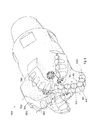
- cutting elements 200 are incorporated onto a drill bit 104 having a body 700 intermediate a shank 701 and a working face 702 .
- the shank 701 may be adapted for connection to a downhole drill string.
- the drill bit 104 of the present invention may be intended for deep oil and gas drilling, although any type of drilling application is anticipated such as horizontal drilling, geothermal drilling, exploration, on and off-shore drilling, directional drilling, water well drilling and any combination thereof.
- the working face 702 may have a plurality of blades 703 converging at a center 704 of the working face 702 and diverging towards a gauge portion 705 of the working face 702 .
- the drill bit 104 may have between three and seven blades 703 .
- At least one blade 703 may have at least one cutting element 200 with a carbide substrate bonded to a diamond working end with a pointed geometry.
- Cutting elements 200 may be arrayed along any portion of the blades 703 , including a cone portion 706 , a nose portion 707 , a flank portion 708 , and the gauge portion 705 .
- a plurality of nozzles 709 may be disposed into recesses 710 formed in the working face 702 . Each nozzle 709 may be oriented such that a jet of drilling mud ejected from the nozzles 709 engages the formation before or after the cutting elements 200 .
- the jets of drilling mud may also be used to clean cuttings away from the drill bit 104 .
- FIGS. 2 through 5 are cross-sectional diagrams of a cutting element 200 A, 200 B, and 200 C in contact with a formation 105 A, 105 B, 105 C, and 105 D, respectively.
- Each cutting element 200 A, 200 B, and 200 C has a carbide substrate 201 A, 201 B, and 200 C, respectively, bonded to a diamond working end 202 A, 202 B, and 202 C, respectively, that includes a pointed geometry.
- the diamond working end 202 A 202 B, and 202 C has a central axis 203 A, 203 B, 203 C which intersects an apex 204 A, 204 B, and 204 C, respectively, of the diamond working end 202 A, 202 B, and 202 C.
- a rake angle 205 A, 205 B, 205 C is formed between the central axis 203 A, 203 B, 203 C of the diamond working end 202 A, 202 B, and 202 C and a vertical axis 206 A, 206 B, and 206 C.
- the central axis 203 A, 203 B, 203 C is oriented between a 25 and 85 degree positive rake angle as discussed below.
- the central axis 203 A, 203 B, 203 C is oriented between a 35 and 50 degree positive rake angle as discussed below.
- FIG. 2 illustrates the a cutting element 200 A at a 60 degree positive rake angle 205 A.
- the cutting element 200 A may be adapted for attachment to a drill bit, the drill bit operating at a low rotation per minute (RPM) and having a high weight-on-bit (WOB).
- RPM rotation per minute
- WOB weight-on-bit
- a vector force 207 A produced by the WOB may be substantially large and downward.
- a slow rotational speed, or low RPM may produce a vector force 208 A substantially pointing in the direction of the central axis 203 A of the cutting element 200 A.
- the sum 209 A of the vector forces 207 A, 208 A may result in the cutting element 200 A cutting a chip 210 A from a formation 105 A in a substantially wedge geometry as shown in FIG. 2 .
- the formation 105 A being drilled may comprise limestone, sandstone, granite, or combinations thereof. It is believed that angling the cutting element 200 A at the given positive rake angle 205 A may produce cuttings having a unit volume of 0.5 to 10 cubic centimeters. Further, 40 to 60 percent of the cuttings produced may have said range of volumes.
- a vertical turret lathe (VTL) test was performed on a cutting element similar to the cutting element shown in FIG. 2 .
- the VTL test was performed at Novatek International, Inc. located in Provo, Utah.
- a cutting element was oriented at a 60 degree positive rake angle adjacent a flat surface of a Sierra White Granite wheel having a six-foot diameter. Such formations may comprise a Mohs hardness of 5.5 to 7.
- the granite wheel rotated at 25 RPM while the cutting element was held constant at a 0.250 inch depth of cut into the granite formation during the test.
- the apex of the diamond working end had a radius of 0.094 inch.
- the diamond was produced by a high pressure and high temperature (HPHT) method using HPHT containers or can assemblies.
- HPHT high pressure and high temperature
- No. 11/469,229 which is incorporated by reference for all that it contains, discloses an improved assembly for HPHT processing that was used to produce the diamond working end used in this VTL test.
- a can with an opening contains a mixture comprising diamond powder, a substrate being positioned adjacent and above the mixture.
- a stop-off is positioned atop the substrate as well as first and second lid.
- a meltable sealant is positioned intermediate the second lid and a cap covering the opening.
- the assembly is heated to a cleansing temperature for a period of time.
- the assembly is then heated to a sealing temperature for another period of time.
- a cutting element 200 A may be positioned at a 60 degree positive rake angle 205 A adjacent the formation 105 B.
- the cutting element 200 A may be adapted for connection to a drill string operating at a high RPM and a low WOB.
- a downward force vector 207 B produced by the WOB may have a relatively small magnitude while a force vector 208 B produced by the RPM may be substantially horizontal.
- the cutting element 200 A shown in FIG. 3 may produce a longer and narrower chip 210 B than the chip 210 A shown in FIG. 2 because of the different operating parameters, namely the WOB and RPM applied to the cutting element 200 A in FIG. 3 .
- the chip 210 B may comprise a substantially wedge geometry tapering at a 5 to 30 degree incline angle 300 A.
- the cutting element 200 A may comprise a length 350 of 0.250 to 1.50 inches. It may be beneficial to have a cutting element comprising a small length, or moment arm, such that the torque experienced during a drilling operation may be minimal and thereby extending the life of the cutting element.
- the cutting element 200 A may also produce a 0.100 to 0.350 inch depth of cut 301 during a drilling operation.
- the depth of cut 301 A may be dependent on the WOB and RPM specific to the drilling operation.
- the positive rake angle 205 A may also vary the depth of cut 301 . For example, a cutting element 200 A operating at a low WOB and a high RPM, such as illustrated in FIG.
- a cutting element having a larger positive rake angle may produce a smaller depth of cut than a cutting element having a smaller positive rake angle.
- a smaller rake angle 205 B is shown for a cutting elements 200 B operated under different conditions in FIGS. 4 and 5 .
- the cutting element 200 B is positioned adjacent a formation 105 C and 105 D at a 45 degree positive rake angle 205 B.
- the cutting element 200 B may be operated at a high WOB and low RPM, whereas in FIG. 5 the cutting element 200 B is operated with a low WOB and high RPM.
- the chip 210 C produced by the cutting element 200 B in FIG. 4 may have a wedge geometry and may have a greater incline angle 300 B than the incline angle 300 C of the chip 210 D shown in FIG. 5 .
- the cutting element 200 may be incorporated into a high impact resistant tool 600 , which is adapted for connection to some types of shear bits, such as the water well drill bit and horizontal drill bit shown in FIGS. 19 and 20 .
- the cutting element 200 may have a diamond working end 202 attached to a carbide substrate 201 , the diamond working end 202 having a pointed geometry 601 .
- the pointed geometry 601 may comprise an apex 204 having a 0.050 to 0.200 inch radius 603 .
- the diamond working end 202 may have a 0.090 to 0.500 inch thickness 604 from the apex 204 to a non-planar interface 605 between the diamond working end 202 and the carbide substrate 201 .
- the diamond working end 202 may comprise diamond, polycrystalline diamond, natural diamond, synthetic diamond, vapor deposited diamond, silicon bonded diamond, cobalt bonded diamond, thermally stable diamond, infiltrated diamond, layered diamond, cubic boron nitride, diamond impregnated matrix, diamond impregnated carbide, metal catalyzed diamond, or combinations thereof. It is believed that a sharp thick geometry of the diamond working end 202 as shown in this embodiment may be able to withstand forces experienced during a drilling operation better than a diamond working end having a blunt geometry or a thin geometry.
- a drill bit 104 A may have a working face 702 A having a plurality of blades 703 A converging at a center of the working face 702 A and diverging towards a gauge portion 705 A of the working face 702 A.
- At least one of the blades 703 A may have at least one cutting element 200 C with a carbide substrate bonded to a diamond working end with a pointed geometry.
- Cutting elements 200 C may be arrayed along any portion of the blades 703 B- F, including a cone portion 706 A, a nose portion 707 A, a flank portion 708 A, and the gauge portion 705 A.
- At least one blade such as blade 703 F may have at least one shear cutting element 711 F positioned along the gauge portion 705 F of the blade 703 F.
- at least one shear cutting element 711 D may be arrayed along any portion of the blade, such as blade 703 D.
- the shear cutting elements and pointed cutting elements may be situated along the blade in any arrangement.
- a jack element 712 coaxial with an axis of rotation 713 may extend out of an opening 714 of the working face 702 A.
- the central axis 203 C of the cutting element 200 D may be positioned at an angle 800 relative to a cutting path formed by the working face 702 B of the drill bit 104 B during a downhole drilling operation. It may be beneficial to angle the cutting elements relative to the cutting path so that the cutting elements may break up the formation more efficiently by cutting the formation into larger chips.
- a cutting element 801 on a blade 802 may be oriented at an angle 804 different from the angle 805 of an adjacent cutting element 803 on the same blade 802 .
- cutting elements 801 on the blade 802 nearest the center 704 B of the working face 702 B of the drill bit 104 B may be angled away from a center of the circular cutting path while cutting elements 803 nearer the gauge portion 705 B of the working face 702 B may be angled toward the center of the cutting path. This may be beneficial in that cuttings may be forced away from the center of the working face and thereby may be more easily carried to the top of the wellbore.
- the central axis 203 D of the cutting element 200 F may be positioned at an angle 800 A relative to a cutting path formed by the working face 702 C of the drill bit 104 C during a downhole drilling operation. As noted above in the discussion of FIG. 8 , it may be beneficial to angle the cutting elements relative to the cutting path so that the cutting elements may break up the formation more efficiently by cutting the formation into larger chips.
- FIG. 9 shows an embodiment of a drill bit 104 D in which an angle 900 of at least one cutting element 901 on a blade 902 A is offset from an angle 903 of at least one cutting element 904 on an adjacent blade 905 .
- This orientation may be beneficial in that one blade having all its cutting elements at a common angle relative to a cutting path may offset cutting elements on another blade having another common angle. This may result in a more efficient drilling operation.
- FIG. 9 a discloses the drill bit 104 C with a plurality of cutting elements like element 901 on blade 902 A of the face 702 C. At least one of the cutting elements is bonded to a tapered carbide backing 950 which is brazed into the blade 902 E. In some embodiments the angle of the tapered carbide backing 950 t may be between 5 and 30 degrees. In some embodiments, the blades 902 A, 902 B, 902 C, 902 D, and 902 E surround at least 3 ⁇ 4 of the circumference of the tapered carbide backing 950 proximate the cutting element.
- the combination of the taper of the tapered carbide backing 950 and the blades 902 A, 902 B, 902 C, 902 D, and 902 E surrounding a majority of the circumference of the tapered carbide backing 950 may mechanically lock the tapered carbide backing 950 and, consequently, the cutting elements 901 in the blades 902 A, 902 B, 902 C, 902 D, and 902 E.
- a proximal end 951 of the tapered carbide backing 950 may be situated in a pocket such that when a force is applied to the cutting element 901 the force may be transferred through the tapered carbide backing 950 and generate a hoop tension in the blades 902 A, 902 B, 902 C, 902 D, and 902 E.
- a jack element 712 C may protrude out of the working face 702 C such that an unsupported distal end of the jack element 712 C may protrude between 0.5 to 1.5 inches.
- a portion of the jack element 712 C supported by the bit body may be greater than an unsupported portion.
- the bit body may comprise steel, matrix, carbide, or combinations thereof.
- the jack element 712 C may be brazed directly into a pocket formed in the bit body or it may be press fit into the bit body.
- the central axis 203 E of a cutting element 1000 may run tangent to a cutting path 1001 formed by the working face of the drill bit during a downhole drilling operation.
- the central axis 203 F, 203 G, and 203 H of other cutting elements 1007 , 1002 , 1003 , respectively, may be angled away from a center 1004 of the cutting path 1001 .
- the central axis 203 G of the cutting element 1002 may form a smaller angle 1005 with the cutting path 1001 than an angle 1006 formed by the central axis 203 H and the cutting path 1001 of the cutting element 1003 .
- the central axis 203 F of a cutting element 1007 may form an angle 1008 with the cutting path 1001 such that the cutting element 1007 angles towards the center 1004 .
- FIGS. 11 through 18 show various embodiments of a cutting element 200 H-O with a diamond working end 202 H-O bonded to a carbide substrate 201 H-O; the diamond working ends 202 H-O each have a tapered surface and a pointed geometry.
- FIG. 11 illustrates a pointed geometry 601 H having a concave side 1150 and a continuous convex geometry 1151 at an interface 605 H between the substrate 201 H and the diamond working end 202 H.
- FIG. 12 comprises an embodiment of a diamond working end 202 I having a thickness 604 from the apex 602 to a non-planar interface 605 I, while still maintaining a radius 603 of 0.050 to 0.200 inch.
- the diamond working end 202 I may comprise a thickness 604 of 0.050 to 0.500 inch.
- the carbide substrate 201 I may comprise a thickness 1200 of 0.200 to 1 inch from a base 1201 of the carbide substrate 201 I to the non-planar interface 605 I.
- FIG. 13 illustrates grooves 1300 formed in the carbide substrate 201 J. It is believed that the grooves 1300 may help to increase the strength of the cutting element 200 J at an interface 605 J between the diamond working end 202 J and the carbide substrate 201 J.
- FIG. 14 illustrates a slightly concave geometry 1400 at a non-planar interface 605 K and a concave side 1150 to the diamond working end 202 K.
- FIG. 15 discloses a slightly convex side 1500 of the pointed geometry 601 L of the diamond working end 202 L while still maintaining a 0.050 to 0.200 inch radius.
- FIG. 16 discloses the diamond working end 202 M has a flat sided pointed geometry 1600 .
- FIG. 17 discloses a concave portion 1700 and a convex portion 1701 of the carbide substrate 201 N with a generally flatted central portion 1702 .
- the diamond working end 202 O may have a convex surface comprising different general angles at a lower portion 1800 , a middle portion 1801 , and an upper portion 1802 with respect to the central axis 1804 of the cutting element 200 O.
- the lower portion 1800 of the side surface may be angled at substantially 25 to 33 degrees from the central axis 1804 ; the middle portion 1801 , which may make up a majority of the convex surface, may be angled at substantially 33 to 40 degrees from the central axis 1804 ; and the upper portion 1802 of the convex surface may be angled at substantially 40 to 50 degrees from the central axis 1804 .
- FIGS. 19 and 20 disclose various wear applications that may be incorporated with the present invention.
- FIG. 19 is a drill bit 1900 typically used in water well drilling.
- FIG. 20 is a drill bit 2000 typically used in subterranean, horizontal drilling. These bits 1900 , 2000 , and other bits, may be consistent with the present invention.
- FIG. 21 is a method 2100 of an embodiment for forming a wellbore.
- the method 2100 may include providing 2101 a drill bit with a body intermediate a shank and a working face, the working face comprising a plurality of blades extending outwardly from the bit body, at least one blade comprising a cutting element with a carbide substrate bonded to a diamond working end with a pointed geometry.
- the method 2100 also includes deploying 2102 the drill bit on a drill string within a wellbore and positioning the diamond working end adjacent a downhole formation between a 25 and 85 degree positive rake angle with respect to a central axis of the drill bit.
- the method 2100 further includes degrading 2103 the downhole formation with the diamond working end. 40 to 60 percent of the cuttings produced by the cutting element may have a volume of 0.5 to 10 cubic centimeters.
Abstract
Description
Claims (14)
Priority Applications (7)
| Application Number | Priority Date | Filing Date | Title |
|---|---|---|---|
| US11/829,577 US8622155B2 (en) | 2006-08-11 | 2007-07-27 | Pointed diamond working ends on a shear bit |
| US11/861,641 US8590644B2 (en) | 2006-08-11 | 2007-09-26 | Downhole drill bit |
| US14/089,385 US9051795B2 (en) | 2006-08-11 | 2013-11-25 | Downhole drill bit |
| US14/101,972 US9145742B2 (en) | 2006-08-11 | 2013-12-10 | Pointed working ends on a drill bit |
| US14/717,567 US9708856B2 (en) | 2006-08-11 | 2015-05-20 | Downhole drill bit |
| US14/829,037 US9915102B2 (en) | 2006-08-11 | 2015-08-18 | Pointed working ends on a bit |
| US15/651,308 US10378288B2 (en) | 2006-08-11 | 2017-07-17 | Downhole drill bit incorporating cutting elements of different geometries |
Applications Claiming Priority (16)
| Application Number | Priority Date | Filing Date | Title |
|---|---|---|---|
| US11/463,953 US7464993B2 (en) | 2006-08-11 | 2006-08-11 | Attack tool |
| US11/463,990 US7320505B1 (en) | 2006-08-11 | 2006-08-11 | Attack tool |
| US11/463,975 US7445294B2 (en) | 2006-08-11 | 2006-08-11 | Attack tool |
| US11/463,962 US7413256B2 (en) | 2006-08-11 | 2006-08-11 | Washer for a degradation assembly |
| US11/464,008 US7338135B1 (en) | 2006-08-11 | 2006-08-11 | Holder for a degradation assembly |
| US11/463,998 US7384105B2 (en) | 2006-08-11 | 2006-08-11 | Attack tool |
| US11/686,831 US7568770B2 (en) | 2006-06-16 | 2007-03-15 | Superhard composite material bonded to a steel body |
| US11/695,672 US7396086B1 (en) | 2007-03-15 | 2007-04-03 | Press-fit pick |
| US11/742,261 US7469971B2 (en) | 2006-08-11 | 2007-04-30 | Lubricated pick |
| US11/742,304 US7475948B2 (en) | 2006-08-11 | 2007-04-30 | Pick with a bearing |
| US76686507A | 2007-06-22 | 2007-06-22 | |
| US11/766,975 US8122980B2 (en) | 2007-06-22 | 2007-06-22 | Rotary drag bit with pointed cutting elements |
| US11/766,903 US20130341999A1 (en) | 2006-08-11 | 2007-06-22 | Attack Tool with an Interruption |
| US11/773,271 US7997661B2 (en) | 2006-08-11 | 2007-07-03 | Tapered bore in a pick |
| US11/774,227 US7669938B2 (en) | 2006-08-11 | 2007-07-06 | Carbide stem press fit into a steel body of a pick |
| US11/829,577 US8622155B2 (en) | 2006-08-11 | 2007-07-27 | Pointed diamond working ends on a shear bit |
Related Parent Applications (3)
| Application Number | Title | Priority Date | Filing Date |
|---|---|---|---|
| US11/695,672 Continuation-In-Part US7396086B1 (en) | 2006-08-11 | 2007-04-03 | Press-fit pick |
| US11/766,975 Continuation-In-Part US8122980B2 (en) | 2006-08-11 | 2007-06-22 | Rotary drag bit with pointed cutting elements |
| US11/774,227 Continuation-In-Part US7669938B2 (en) | 2006-08-11 | 2007-07-06 | Carbide stem press fit into a steel body of a pick |
Related Child Applications (3)
| Application Number | Title | Priority Date | Filing Date |
|---|---|---|---|
| US11/463,975 Continuation-In-Part US7445294B2 (en) | 2006-08-11 | 2006-08-11 | Attack tool |
| US11/861,641 Continuation-In-Part US8590644B2 (en) | 2006-08-11 | 2007-09-26 | Downhole drill bit |
| US14/101,972 Continuation US9145742B2 (en) | 2006-08-11 | 2013-12-10 | Pointed working ends on a drill bit |
Publications (2)
| Publication Number | Publication Date |
|---|---|
| US20080035380A1 US20080035380A1 (en) | 2008-02-14 |
| US8622155B2 true US8622155B2 (en) | 2014-01-07 |
Family
ID=39049508
Family Applications (1)
| Application Number | Title | Priority Date | Filing Date |
|---|---|---|---|
| US11/829,577 Active 2027-05-10 US8622155B2 (en) | 2006-08-11 | 2007-07-27 | Pointed diamond working ends on a shear bit |
Country Status (1)
| Country | Link |
|---|---|
| US (1) | US8622155B2 (en) |
Cited By (5)
| Publication number | Priority date | Publication date | Assignee | Title |
|---|---|---|---|---|
| US20130087391A1 (en) * | 2009-10-14 | 2013-04-11 | David R. Hall | Fixed bladed drill bit cutter profile |
| US20140097028A1 (en) * | 2006-08-11 | 2014-04-10 | Schlumberger Technology Corporation | Pointed diamond working ends on a shear bit |
| US9404310B1 (en) * | 2012-03-01 | 2016-08-02 | Us Synthetic Corporation | Polycrystalline diamond compacts including a domed polycrystalline diamond table, and applications therefor |
| US9708856B2 (en) | 2006-08-11 | 2017-07-18 | Smith International, Inc. | Downhole drill bit |
| US10590710B2 (en) | 2016-12-09 | 2020-03-17 | Baker Hughes, A Ge Company, Llc | Cutting elements, earth-boring tools including the cutting elements, and methods of forming the cutting elements |
Families Citing this family (26)
| Publication number | Priority date | Publication date | Assignee | Title |
|---|---|---|---|---|
| US8839888B2 (en) * | 2010-04-23 | 2014-09-23 | Schlumberger Technology Corporation | Tracking shearing cutters on a fixed bladed drill bit with pointed cutting elements |
| JP5336597B2 (en) * | 2008-08-18 | 2013-11-06 | サンドビック インテレクチュアル プロパティー アクティエボラーグ | Sleeve retainer for tool step shank |
| US8459357B2 (en) * | 2009-05-04 | 2013-06-11 | Smith International, Inc. | Milling system and method of milling |
| US8505634B2 (en) * | 2009-12-28 | 2013-08-13 | Baker Hughes Incorporated | Earth-boring tools having differing cutting elements on a blade and related methods |
| WO2011097575A2 (en) * | 2010-02-05 | 2011-08-11 | Baker Hughes Incorporated | Shaped cutting elements on drill bits and other earth-boring tools, and methods of forming same |
| CN102933785B (en) | 2010-04-23 | 2016-01-13 | 贝克休斯公司 | The cutting element of earth-boring tools, comprise the earth-boring tools of this cutting element with and related methods |
| US8418784B2 (en) | 2010-05-11 | 2013-04-16 | David R. Hall | Central cutting region of a drilling head assembly |
| US8851207B2 (en) | 2011-05-05 | 2014-10-07 | Baker Hughes Incorporated | Earth-boring tools and methods of forming such earth-boring tools |
| SA111320671B1 (en) | 2010-08-06 | 2015-01-22 | بيكر هوغيس انكور | Shaped cutting elements for earth boring tools, earth boring tools including such cutting elements, and related methods |
| US8550188B2 (en) | 2010-09-29 | 2013-10-08 | Smith International, Inc. | Downhole reamer asymmetric cutting structures |
| GB2503145B (en) * | 2011-02-10 | 2019-05-15 | Smith International | Kerfing hybrid drill bit and other downhole cutting tools |
| US9243452B2 (en) * | 2011-04-22 | 2016-01-26 | Baker Hughes Incorporated | Cutting elements for earth-boring tools, earth-boring tools including such cutting elements, and related methods |
| US9650837B2 (en) | 2011-04-22 | 2017-05-16 | Baker Hughes Incorporated | Multi-chamfer cutting elements having a shaped cutting face and earth-boring tools including such cutting elements |
| US9428966B2 (en) | 2012-05-01 | 2016-08-30 | Baker Hughes Incorporated | Cutting elements for earth-boring tools, earth-boring tools including such cutting elements, and related methods |
| US8991525B2 (en) | 2012-05-01 | 2015-03-31 | Baker Hughes Incorporated | Earth-boring tools having cutting elements with cutting faces exhibiting multiple coefficients of friction, and related methods |
| US9482057B2 (en) | 2011-09-16 | 2016-11-01 | Baker Hughes Incorporated | Cutting elements for earth-boring tools, earth-boring tools including such cutting elements and related methods |
| US9347275B2 (en) | 2011-06-22 | 2016-05-24 | Smith International, Inc. | Fixed cutter drill bit with core fragmentation feature |
| US9212523B2 (en) | 2011-12-01 | 2015-12-15 | Smith International, Inc. | Drill bit having geometrically sharp inserts |
| BR112014019574A8 (en) | 2012-02-08 | 2017-07-11 | Baker Hughes Inc | MOLDED CUTTING ELEMENTS FOR EARTH DRILLING TOOLS AND EARTH DRILLING TOOLS INCLUDING SUCH CUTTING ELEMENTS |
| US9464490B2 (en) | 2012-05-03 | 2016-10-11 | Smith International, Inc. | Gage cutter protection for drilling bits |
| US10030452B2 (en) | 2013-03-14 | 2018-07-24 | Smith International, Inc. | Cutting structures for fixed cutter drill bit and other downhole cutting tools |
| US10309156B2 (en) | 2013-03-14 | 2019-06-04 | Smith International, Inc. | Cutting structures for fixed cutter drill bit and other downhole cutting tools |
| US10287825B2 (en) | 2014-03-11 | 2019-05-14 | Smith International, Inc. | Cutting elements having non-planar surfaces and downhole cutting tools using such cutting elements |
| US10145180B2 (en) | 2014-08-26 | 2018-12-04 | Smith International, Inc. | Hybrid cutting structures with blade undulations |
| US10753156B2 (en) | 2014-09-02 | 2020-08-25 | Smith International, Inc. | Cutting element backing support |
| US10125548B2 (en) | 2014-12-22 | 2018-11-13 | Smith International, Inc. | Drill bits with core feature for directional drilling applications and methods of use thereof |
Citations (375)
| Publication number | Priority date | Publication date | Assignee | Title |
|---|---|---|---|---|
| US465103A (en) | 1891-12-15 | Combined drill | ||
| US616118A (en) | 1898-12-20 | Ernest kuhne | ||
| US946060A (en) | 1908-10-10 | 1910-01-11 | David W Looker | Post-hole auger. |
| US1116154A (en) | 1913-03-26 | 1914-11-03 | William G Stowers | Post-hole digger. |
| US1183630A (en) | 1915-06-29 | 1916-05-16 | Charles R Bryson | Underreamer. |
| US1189560A (en) | 1914-10-21 | 1916-07-04 | Georg Gondos | Rotary drill. |
| US1360908A (en) | 1920-07-16 | 1920-11-30 | Everson August | Reamer |
| US1387733A (en) | 1921-02-15 | 1921-08-16 | Penelton G Midgett | Well-drilling bit |
| US1460671A (en) | 1920-06-17 | 1923-07-03 | Hebsacker Wilhelm | Excavating machine |
| US1544757A (en) | 1923-02-05 | 1925-07-07 | Hufford | Oil-well reamer |
| US1821474A (en) | 1927-12-05 | 1931-09-01 | Sullivan Machinery Co | Boring tool |
| US1879177A (en) | 1930-05-16 | 1932-09-27 | W J Newman Company | Drilling apparatus for large wells |
| US2004315A (en) | 1932-08-29 | 1935-06-11 | Thomas R Mcdonald | Packing liner |
| US2054255A (en) | 1934-11-13 | 1936-09-15 | John H Howard | Well drilling tool |
| US2064255A (en) | 1936-06-19 | 1936-12-15 | Hughes Tool Co | Removable core breaker |
| US2121202A (en) | 1935-03-19 | 1938-06-21 | Robert J Killgore | Rotary bit |
| US2124438A (en) | 1935-04-05 | 1938-07-19 | Gen Electric | Soldered article or machine part |
| US2169223A (en) | 1937-04-10 | 1939-08-15 | Carl C Christian | Drilling apparatus |
| US2218130A (en) | 1938-06-14 | 1940-10-15 | Shell Dev | Hydraulic disruption of solids |
| US2320136A (en) | 1940-09-30 | 1943-05-25 | Archer W Kammerer | Well drilling bit |
| US2466991A (en) | 1945-06-06 | 1949-04-12 | Archer W Kammerer | Rotary drill bit |
| US2540464A (en) | 1947-05-31 | 1951-02-06 | Reed Roller Bit Co | Pilot bit |
| US2544036A (en) | 1946-09-10 | 1951-03-06 | Edward M Mccann | Cotton chopper |
| US2755071A (en) | 1954-08-25 | 1956-07-17 | Rotary Oil Tool Company | Apparatus for enlarging well bores |
| US2776819A (en) | 1953-10-09 | 1957-01-08 | Philip B Brown | Rock drill bit |
| US2819043A (en) | 1955-06-13 | 1958-01-07 | Homer I Henderson | Combination drilling bit |
| US2838284A (en) | 1956-04-19 | 1958-06-10 | Christensen Diamond Prod Co | Rotary drill bit |
| US2894722A (en) | 1953-03-17 | 1959-07-14 | Ralph Q Buttolph | Method and apparatus for providing a well bore with a deflected extension |
| US2901223A (en) | 1955-11-30 | 1959-08-25 | Hughes Tool Co | Earth boring drill |
| US2963102A (en) | 1956-08-13 | 1960-12-06 | James E Smith | Hydraulic drill bit |
| US3135341A (en) | 1960-10-04 | 1964-06-02 | Christensen Diamond Prod Co | Diamond drill bits |
| US3254392A (en) | 1963-11-13 | 1966-06-07 | Warner Swasey Co | Insert bit for cutoff and like tools |
| US3294186A (en) | 1964-06-22 | 1966-12-27 | Tartan Ind Inc | Rock bits and methods of making the same |
| US3301339A (en) | 1964-06-19 | 1967-01-31 | Exxon Production Research Co | Drill bit with wear resistant material on blade |
| US3379264A (en) | 1964-11-05 | 1968-04-23 | Dravo Corp | Earth boring machine |
| US3397012A (en) | 1966-12-19 | 1968-08-13 | Cincinnati Mine Machinery Co | Cutter bits and means for mounting them |
| US3429390A (en) | 1967-05-19 | 1969-02-25 | Supercussion Drills Inc | Earth-drilling bits |
| US3493165A (en) | 1966-11-18 | 1970-02-03 | Georg Schonfeld | Continuous tunnel borer |
| US3583504A (en) | 1969-02-24 | 1971-06-08 | Mission Mfg Co | Gauge cutting bit |
| US3626775A (en) | 1970-10-07 | 1971-12-14 | Gates Rubber Co | Method of determining notch configuration in a belt |
| US3745396A (en) | 1972-05-25 | 1973-07-10 | Energy Sciences Inc | Elongated electron-emission cathode assembly and method |
| US3745623A (en) | 1971-12-27 | 1973-07-17 | Gen Electric | Diamond tools for machining |
| US3746396A (en) | 1970-12-31 | 1973-07-17 | Continental Oil Co | Cutter bit and method of causing rotation thereof |
| US3764493A (en) | 1972-08-31 | 1973-10-09 | Us Interior | Recovery of nickel and cobalt |
| US3800891A (en) | 1968-04-18 | 1974-04-02 | Hughes Tool Co | Hardfacing compositions and gage hardfacing on rolling cutter rock bits |
| US3807804A (en) | 1972-09-12 | 1974-04-30 | Kennametal Inc | Impacting tool with tungsten carbide insert tip |
| US3821993A (en) * | 1971-09-07 | 1974-07-02 | Kennametal Inc | Auger arrangement |
| US3830321A (en) | 1973-02-20 | 1974-08-20 | Kennametal Inc | Excavating tool and a bit for use therewith |
| US3932952A (en) | 1973-12-17 | 1976-01-20 | Caterpillar Tractor Co. | Multi-material ripper tip |
| US3945681A (en) | 1973-12-07 | 1976-03-23 | Western Rock Bit Company Limited | Cutter assembly |
| US3955635A (en) | 1975-02-03 | 1976-05-11 | Skidmore Sam C | Percussion drill bit |
| US3960223A (en) | 1974-03-26 | 1976-06-01 | Gebrueder Heller | Drill for rock |
| US4005914A (en) | 1974-08-20 | 1977-02-01 | Rolls-Royce (1971) Limited | Surface coating for machine elements having rubbing surfaces |
| US4006936A (en) | 1975-11-06 | 1977-02-08 | Dresser Industries, Inc. | Rotary cutter for a road planer |
| US4081042A (en) | 1976-07-08 | 1978-03-28 | Tri-State Oil Tool Industries, Inc. | Stabilizer and rotary expansible drill bit apparatus |
| US4096917A (en) | 1975-09-29 | 1978-06-27 | Harris Jesse W | Earth drilling knobby bit |
| US4098362A (en) | 1976-11-30 | 1978-07-04 | General Electric Company | Rotary drill bit and method for making same |
| US4106577A (en) | 1977-06-20 | 1978-08-15 | The Curators Of The University Of Missouri | Hydromechanical drilling device |
| US4109737A (en) | 1976-06-24 | 1978-08-29 | General Electric Company | Rotary drill bit |
| US4140004A (en) | 1977-11-09 | 1979-02-20 | Stauffer Chemical Company | Apparatus for determining the explosion limits of a flammable gas |
| US4156329A (en) | 1977-05-13 | 1979-05-29 | General Electric Company | Method for fabricating a rotary drill bit and composite compact cutters therefor |
| US4176723A (en) | 1977-11-11 | 1979-12-04 | DTL, Incorporated | Diamond drill bit |
| US4199035A (en) | 1978-04-24 | 1980-04-22 | General Electric Company | Cutting and drilling apparatus with threadably attached compacts |
| US4201421A (en) | 1978-09-20 | 1980-05-06 | Besten Leroy E Den | Mining machine bit and mounting thereof |
| US4211508A (en) | 1974-07-03 | 1980-07-08 | Hughes Tool Company | Earth boring tool with improved inserts |
| US4224380A (en) | 1978-03-28 | 1980-09-23 | General Electric Company | Temperature resistant abrasive compact and method for making same |
| US4253533A (en) | 1979-11-05 | 1981-03-03 | Smith International, Inc. | Variable wear pad for crossflow drag bit |
| US4268089A (en) | 1978-05-31 | 1981-05-19 | Winster Mining Limited | Mounting means for pick on mining drum vane |
| US4277106A (en) | 1979-10-22 | 1981-07-07 | Syndrill Carbide Diamond Company | Self renewing working tip mining pick |
| US4280573A (en) | 1979-06-13 | 1981-07-28 | Sudnishnikov Boris V | Rock-breaking tool for percussive-action machines |
| US4304312A (en) | 1980-01-11 | 1981-12-08 | Sandvik Aktiebolag | Percussion drill bit having centrally projecting insert |
| US4307786A (en) | 1978-07-27 | 1981-12-29 | Evans Robert F | Borehole angle control by gage corner removal effects from hydraulic fluid jet |
| USD264217S (en) | 1979-07-17 | 1982-05-04 | Prause Benjiman G | Drill bit protector |
| US4333986A (en) | 1979-06-11 | 1982-06-08 | Sumitomo Electric Industries, Ltd. | Diamond sintered compact wherein crystal particles are uniformly orientated in a particular direction and a method for producing the same |
| US4333902A (en) | 1977-01-24 | 1982-06-08 | Sumitomo Electric Industries, Ltd. | Process of producing a sintered compact |
| US4337980A (en) | 1979-05-21 | 1982-07-06 | The Cincinnati Mine Machinery Company | Wedge arrangements and related means for mounting means, base members, and bits, and combinations thereof, for mining, road working, or earth moving machinery |
| US4390992A (en) | 1981-07-17 | 1983-06-28 | The United States Of America As Represented By The United States Department Of Energy | Plasma channel optical pumping device and method |
| US4397361A (en) | 1981-06-01 | 1983-08-09 | Dresser Industries, Inc. | Abradable cutter protection |
| US4416339A (en) | 1982-01-21 | 1983-11-22 | Baker Royce E | Bit guidance device and method |
| US4439250A (en) | 1983-06-09 | 1984-03-27 | International Business Machines Corporation | Solder/braze-stop composition |
| US4445580A (en) | 1979-06-19 | 1984-05-01 | Syndrill Carbide Diamond Company | Deep hole rock drill bit |
| US4448269A (en) | 1981-10-27 | 1984-05-15 | Hitachi Construction Machinery Co., Ltd. | Cutter head for pit-boring machine |
| US4465221A (en) | 1982-09-28 | 1984-08-14 | Schmidt Glenn H | Method of sustaining metallic golf club head sole plate profile by confined brazing or welding |
| US4481016A (en) | 1978-08-18 | 1984-11-06 | Campbell Nicoll A D | Method of making tool inserts and drill bits |
| US4484783A (en) | 1982-07-22 | 1984-11-27 | Fansteel Inc. | Retainer and wear sleeve for rotating mining bits |
| US4484644A (en) | 1980-09-02 | 1984-11-27 | Ingersoll-Rand Company | Sintered and forged article, and method of forming same |
| US4489986A (en) | 1982-11-01 | 1984-12-25 | Dziak William A | Wear collar device for rotatable cutter bit |
| US4499795A (en) | 1983-09-23 | 1985-02-19 | Strata Bit Corporation | Method of drill bit manufacture |
| US4525178A (en) | 1984-04-16 | 1985-06-25 | Megadiamond Industries, Inc. | Composite polycrystalline diamond |
| US4531592A (en) | 1983-02-07 | 1985-07-30 | Asadollah Hayatdavoudi | Jet nozzle |
| US4535853A (en) | 1982-12-23 | 1985-08-20 | Charbonnages De France | Drill bit for jet assisted rotary drilling |
| US4538691A (en) | 1984-01-30 | 1985-09-03 | Strata Bit Corporation | Rotary drill bit |
| US4566545A (en) | 1983-09-29 | 1986-01-28 | Norton Christensen, Inc. | Coring device with an improved core sleeve and anti-gripping collar with a collective core catcher |
| US4574895A (en) | 1982-02-22 | 1986-03-11 | Hughes Tool Company - Usa | Solid head bit with tungsten carbide central core |
| US4599731A (en) | 1984-04-27 | 1986-07-08 | The United States Of America As Represented By The United States Department Of Energy | Exploding conducting film laser pumping apparatus |
| US4627503A (en) | 1983-08-12 | 1986-12-09 | Megadiamond Industries, Inc. | Multiple layer polycrystalline diamond compact |
| US4636353A (en) | 1983-07-05 | 1987-01-13 | Rhone-Poulenc Specialites Chimiques | Novel neodymium/iron alloys |
| US4636253A (en) | 1984-09-08 | 1987-01-13 | Sumitomo Electric Industries, Ltd. | Diamond sintered body for tools and method of manufacturing same |
| US4640374A (en) | 1984-01-30 | 1987-02-03 | Strata Bit Corporation | Rotary drill bit |
| US4647546A (en) | 1984-10-30 | 1987-03-03 | Megadiamond Industries, Inc. | Polycrystalline cubic boron nitride compact |
| US4647111A (en) | 1984-06-09 | 1987-03-03 | Belzer-Dowidat Gmbh Werkzeug-Union | Sleeve insert mounting for mining pick |
| US4650776A (en) | 1984-10-30 | 1987-03-17 | Smith International, Inc. | Cubic boron nitride compact and method of making |
| US4662348A (en) | 1985-06-20 | 1987-05-05 | Megadiamond, Inc. | Burnishing diamond |
| US4664705A (en) | 1985-07-30 | 1987-05-12 | Sii Megadiamond, Inc. | Infiltrated thermally stable polycrystalline diamond |
| US4678237A (en) | 1982-08-06 | 1987-07-07 | Huddy Diamond Crown Setting Company (Proprietary) Limited | Cutter inserts for picks |
| US4682987A (en) | 1981-04-16 | 1987-07-28 | Brady William J | Method and composition for producing hard surface carbide insert tools |
| US4684176A (en) | 1984-05-16 | 1987-08-04 | Den Besten Leroy E | Cutter bit device |
| US4688856A (en) | 1984-10-27 | 1987-08-25 | Gerd Elfgen | Round cutting tool |
| US4690691A (en) | 1986-02-18 | 1987-09-01 | General Electric Company | Polycrystalline diamond and CBN cutting tools |
| US4694918A (en) | 1985-04-29 | 1987-09-22 | Smith International, Inc. | Rock bit with diamond tip inserts |
| US4725098A (en) | 1986-12-19 | 1988-02-16 | Kennametal Inc. | Erosion resistant cutting bit with hardfacing |
| US4726718A (en) | 1984-03-26 | 1988-02-23 | Eastman Christensen Co. | Multi-component cutting element using triangular, rectangular and higher order polyhedral-shaped polycrystalline diamond disks |
| US4729441A (en) | 1984-07-21 | 1988-03-08 | Hawera Probst Gmbh & Co. | Rock drill |
| US4729603A (en) | 1984-11-22 | 1988-03-08 | Gerd Elfgen | Round cutting tool for cutters |
| US4765686A (en) | 1987-10-01 | 1988-08-23 | Gte Valenite Corporation | Rotatable cutting bit for a mining machine |
| US4765419A (en) | 1985-12-16 | 1988-08-23 | Hilti Aktiengesellschaft | Rock drill with cutting inserts |
| US4765687A (en) | 1986-02-19 | 1988-08-23 | Innovation Limited | Tip and mineral cutter pick |
| US4776862A (en) | 1987-12-08 | 1988-10-11 | Wiand Ronald C | Brazing of diamond |
| US4815342A (en) | 1987-12-15 | 1989-03-28 | Amoco Corporation | Method for modeling and building drill bits |
| US4852672A (en) | 1988-08-15 | 1989-08-01 | Behrens Robert N | Drill apparatus having a primary drill and a pilot drill |
| US4880154A (en) | 1986-04-03 | 1989-11-14 | Klaus Tank | Brazing |
| US4889017A (en) | 1984-07-19 | 1989-12-26 | Reed Tool Co., Ltd. | Rotary drill bit for use in drilling holes in subsurface earth formations |
| USD305871S (en) | 1986-05-16 | 1990-02-06 | A.M.S. | Bottle cap |
| US4921310A (en) | 1987-06-12 | 1990-05-01 | Hedlund Jan Gunnar | Tool for breaking, cutting or working of solid materials |
| US4932723A (en) | 1989-06-29 | 1990-06-12 | Mills Ronald D | Cutting-bit holding support block shield |
| US4940099A (en) | 1989-04-05 | 1990-07-10 | Reed Tool Company | Cutting elements for roller cutter drill bits |
| US4940288A (en) | 1988-07-20 | 1990-07-10 | Kennametal Inc. | Earth engaging cutter bit |
| US4944559A (en) | 1988-06-02 | 1990-07-31 | Societe Industrielle De Combustible Nucleaire | Tool for a mine working machine comprising a diamond-charged abrasive component |
| US4944772A (en) | 1988-11-30 | 1990-07-31 | General Electric Company | Fabrication of supported polycrystalline abrasive compacts |
| US4951762A (en) | 1988-07-28 | 1990-08-28 | Sandvik Ab | Drill bit with cemented carbide inserts |
| US4956238A (en) | 1987-06-12 | 1990-09-11 | Reed Tool Company Limited | Manufacture of cutting structures for rotary drill bits |
| US4962822A (en) | 1989-12-15 | 1990-10-16 | Numa Tool Company | Downhole drill bit and bit coupling |
| US4981184A (en) | 1988-11-21 | 1991-01-01 | Smith International, Inc. | Diamond drag bit for soft formations |
| US5007685A (en) | 1989-01-17 | 1991-04-16 | Kennametal Inc. | Trenching tool assembly with dual indexing capability |
| US5009273A (en) | 1988-01-08 | 1991-04-23 | Foothills Diamond Coring (1980) Ltd. | Deflection apparatus |
| US5011515A (en) | 1989-08-07 | 1991-04-30 | Frushour Robert H | Composite polycrystalline diamond compact with improved impact resistance |
| US5027914A (en) | 1990-06-04 | 1991-07-02 | Wilson Steve B | Pilot casing mill |
| US5038873A (en) | 1989-04-13 | 1991-08-13 | Baker Hughes Incorporated | Drilling tool with retractable pilot drilling unit |
| US5088797A (en) | 1990-09-07 | 1992-02-18 | Joy Technologies Inc. | Method and apparatus for holding a cutting bit |
| USD324056S (en) | 1989-04-03 | 1992-02-18 | General Electric Company | Interlocking mounted abrasive compacts |
| USD324226S (en) | 1989-04-03 | 1992-02-25 | General Electric Company | Interlocking mounted abrasive compacts |
| US5112165A (en) | 1989-04-24 | 1992-05-12 | Sandvik Ab | Tool for cutting solid material |
| US5119714A (en) | 1991-03-01 | 1992-06-09 | Hughes Tool Company | Rotary rock bit with improved diamond filled compacts |
| US5119892A (en) | 1989-11-25 | 1992-06-09 | Reed Tool Company Limited | Notary drill bits |
| US5141289A (en) | 1988-07-20 | 1992-08-25 | Kennametal Inc. | Cemented carbide tip |
| US5141063A (en) | 1990-08-08 | 1992-08-25 | Quesenbury Jimmy B | Restriction enhancement drill |
| USD329809S (en) | 1990-04-04 | 1992-09-29 | Plastic Consulting and Design Limited | Tamperproof cap |
| US5154245A (en) | 1990-04-19 | 1992-10-13 | Sandvik Ab | Diamond rock tools for percussive and rotary crushing rock drilling |
| US5186268A (en) | 1991-10-31 | 1993-02-16 | Camco Drilling Group Ltd. | Rotary drill bits |
| US5186892A (en) | 1991-01-17 | 1993-02-16 | U.S. Synthetic Corporation | Method of healing cracks and flaws in a previously sintered cemented carbide tools |
| US5222566A (en) | 1991-02-01 | 1993-06-29 | Camco Drilling Group Ltd. | Rotary drill bits and methods of designing such drill bits |
| US5248006A (en) | 1991-03-01 | 1993-09-28 | Baker Hughes Incorporated | Rotary rock bit with improved diamond-filled compacts |
| US5251964A (en) | 1992-08-03 | 1993-10-12 | Gte Valenite Corporation | Cutting bit mount having carbide inserts and method for mounting the same |
| US5255749A (en) | 1992-03-16 | 1993-10-26 | Steer-Rite, Ltd. | Steerable burrowing mole |
| US5261499A (en) | 1992-07-15 | 1993-11-16 | Kennametal Inc. | Two-piece rotatable cutting bit |
| US5265682A (en) | 1991-06-25 | 1993-11-30 | Camco Drilling Group Limited | Steerable rotary drilling systems |
| USD342268S (en) | 1991-03-25 | 1993-12-14 | Iggesund Tools Ab | Milling head for woodworking |
| US5303984A (en) | 1992-11-16 | 1994-04-19 | Valenite Inc. | Cutting bit holder sleeve with retaining flange |
| US5304342A (en) | 1992-06-11 | 1994-04-19 | Hall Jr H Tracy | Carbide/metal composite material and a process therefor |
| US5332348A (en) | 1987-03-31 | 1994-07-26 | Lemelson Jerome H | Fastening devices |
| US5332051A (en) * | 1991-10-09 | 1994-07-26 | Smith International, Inc. | Optimized PDC cutting shape |
| US5351770A (en) | 1993-06-15 | 1994-10-04 | Smith International, Inc. | Ultra hard insert cutters for heel row rotary cone rock bit applications |
| US5361859A (en) | 1993-02-12 | 1994-11-08 | Baker Hughes Incorporated | Expandable gage bit for drilling and method of drilling |
| US5374319A (en) | 1990-09-28 | 1994-12-20 | Chromalloy Gas Turbine Corporation | Welding high-strength nickel base superalloys |
| USD357485S (en) | 1993-02-24 | 1995-04-18 | Sandvik Ab | Insert for rock drilling bits |
| US5410303A (en) | 1991-05-15 | 1995-04-25 | Baroid Technology, Inc. | System for drilling deivated boreholes |
| US5417292A (en) | 1993-11-22 | 1995-05-23 | Polakoff; Paul | Large diameter rock drill |
| US5417475A (en) | 1992-08-19 | 1995-05-23 | Sandvik Ab | Tool comprised of a holder body and a hard insert and method of using same |
| US5423389A (en) | 1994-03-25 | 1995-06-13 | Amoco Corporation | Curved drilling apparatus |
| US5447208A (en) | 1993-11-22 | 1995-09-05 | Baker Hughes Incorporated | Superhard cutting element having reduced surface roughness and method of modifying |
| US5494477A (en) | 1993-08-11 | 1996-02-27 | General Electric Company | Abrasive tool insert |
| US5507357A (en) | 1994-02-04 | 1996-04-16 | Foremost Industries, Inc. | Pilot bit for use in auger bit assembly |
| USD371374S (en) | 1995-04-12 | 1996-07-02 | Sandvik Ab | Asymmetrical button insert for rock drilling |
| US5533582A (en) | 1994-12-19 | 1996-07-09 | Baker Hughes, Inc. | Drill bit cutting element |
| US5535839A (en) | 1995-06-07 | 1996-07-16 | Brady; William J. | Roof drill bit with radial domed PCD inserts |
| US5542993A (en) | 1989-10-10 | 1996-08-06 | Alliedsignal Inc. | Low melting nickel-palladium-silicon brazing alloy |
| US5544713A (en) | 1993-08-17 | 1996-08-13 | Dennis Tool Company | Cutting element for drill bits |
| US5560440A (en) | 1993-02-12 | 1996-10-01 | Baker Hughes Incorporated | Bit for subterranean drilling fabricated from separately-formed major components |
| US5568838A (en) | 1994-09-23 | 1996-10-29 | Baker Hughes Incorporated | Bit-stabilized combination coring and drilling system |
| US5655614A (en) | 1994-12-20 | 1997-08-12 | Smith International, Inc. | Self-centering polycrystalline diamond cutting rock bit |
| US5662720A (en) | 1996-01-26 | 1997-09-02 | General Electric Company | Composite polycrystalline diamond compact |
| US5678644A (en) | 1995-08-15 | 1997-10-21 | Diamond Products International, Inc. | Bi-center and bit method for enhancing stability |
| US5709279A (en) | 1995-05-18 | 1998-01-20 | Dennis; Mahlon Denton | Drill bit insert with sinusoidal interface |
| US5720528A (en) | 1996-12-17 | 1998-02-24 | Kennametal Inc. | Rotatable cutting tool-holder assembly |
| US5732784A (en) * | 1996-07-25 | 1998-03-31 | Nelson; Jack R. | Cutting means for drag drill bits |
| US5738698A (en) | 1994-07-29 | 1998-04-14 | Saint Gobain/Norton Company Industrial Ceramics Corp. | Brazing of diamond film to tungsten carbide |
| US5794728A (en) | 1995-06-20 | 1998-08-18 | Sandvik Ab | Percussion rock drill bit |
| US5811944A (en) | 1996-06-25 | 1998-09-22 | The United States Of America As Represented By The Department Of Energy | Enhanced dielectric-wall linear accelerator |
| US5823632A (en) | 1996-06-13 | 1998-10-20 | Burkett; Kenneth H. | Self-sharpening nosepiece with skirt for attack tools |
| US5837071A (en) | 1993-11-03 | 1998-11-17 | Sandvik Ab | Diamond coated cutting tool insert and method of making same |
| US5845547A (en) | 1996-09-09 | 1998-12-08 | The Sollami Company | Tool having a tungsten carbide insert |
| US5848657A (en) | 1996-12-27 | 1998-12-15 | General Electric Company | Polycrystalline diamond cutting element |
| US5871060A (en) | 1997-02-20 | 1999-02-16 | Jensen; Kenneth M. | Attachment geometry for non-planar drill inserts |
| US5875862A (en) | 1995-07-14 | 1999-03-02 | U.S. Synthetic Corporation | Polycrystalline diamond cutter with integral carbide/diamond transition layer |
| US5884979A (en) | 1997-04-17 | 1999-03-23 | Keystone Engineering & Manufacturing Corporation | Cutting bit holder and support surface |
| US5890552A (en) | 1992-01-31 | 1999-04-06 | Baker Hughes Incorporated | Superabrasive-tipped inserts for earth-boring drill bits |
| US5896938A (en) | 1995-12-01 | 1999-04-27 | Tetra Corporation | Portable electrohydraulic mining drill |
| US5914055A (en) | 1996-11-18 | 1999-06-22 | Tennessee Valley Authority | Rotor repair system and technique |
| US5934542A (en) | 1994-03-31 | 1999-08-10 | Sumitomo Electric Industries, Inc. | High strength bonding tool and a process for production of the same |
| US5935718A (en) | 1994-11-07 | 1999-08-10 | General Electric Company | Braze blocking insert for liquid phase brazing operation |
| US5944129A (en) | 1997-11-28 | 1999-08-31 | U.S. Synthetic Corporation | Surface finish for non-planar inserts |
| US5947215A (en) | 1997-11-06 | 1999-09-07 | Sandvik Ab | Diamond enhanced rock drill bit for percussive drilling |
| US5950743A (en) | 1997-02-05 | 1999-09-14 | Cox; David M. | Method for horizontal directional drilling of rock formations |
| US5957223A (en) | 1997-03-05 | 1999-09-28 | Baker Hughes Incorporated | Bi-center drill bit with enhanced stabilizing features |
| US5957225A (en) | 1997-07-31 | 1999-09-28 | Bp Amoco Corporation | Drilling assembly and method of drilling for unstable and depleted formations |
| US5967247A (en) | 1997-09-08 | 1999-10-19 | Baker Hughes Incorporated | Steerable rotary drag bit with longitudinally variable gage aggressiveness |
| US5979571A (en) | 1996-09-27 | 1999-11-09 | Baker Hughes Incorporated | Combination milling tool and drill bit |
| US5992547A (en) | 1995-10-10 | 1999-11-30 | Camco International (Uk) Limited | Rotary drill bits |
| US5992405A (en) | 1998-01-02 | 1999-11-30 | The Sollami Company | Tool mounting for a cutting tool |
| US5992548A (en) | 1995-08-15 | 1999-11-30 | Diamond Products International, Inc. | Bi-center bit with oppositely disposed cutting surfaces |
| US6000483A (en) | 1996-02-15 | 1999-12-14 | Baker Hughes Incorporated | Superabrasive cutting element with enhanced durability and increased wear life, and apparatus so equipped |
| US6003623A (en) | 1998-04-24 | 1999-12-21 | Dresser Industries, Inc. | Cutters and bits for terrestrial boring |
| US6006846A (en) | 1997-09-19 | 1999-12-28 | Baker Hughes Incorporated | Cutting element, drill bit, system and method for drilling soft plastic formations |
| US6018729A (en) | 1997-09-17 | 2000-01-25 | Lockheed Martin Energy Research Corporation | Neural network control of spot welding |
| US6019434A (en) | 1997-10-07 | 2000-02-01 | Fansteel Inc. | Point attack bit |
| US6021859A (en) | 1993-12-09 | 2000-02-08 | Baker Hughes Incorporated | Stress related placement of engineered superabrasive cutting elements on rotary drag bits |
| US6039131A (en) | 1997-08-25 | 2000-03-21 | Smith International, Inc. | Directional drift and drill PDC drill bit |
| US6041875A (en) | 1996-12-06 | 2000-03-28 | Smith International, Inc. | Non-planar interfaces for cutting elements |
| US6044920A (en) | 1997-07-15 | 2000-04-04 | Kennametal Inc. | Rotatable cutting bit assembly with cutting inserts |
| US6056911A (en) | 1998-05-27 | 2000-05-02 | Camco International (Uk) Limited | Methods of treating preform elements including polycrystalline diamond bonded to a substrate |
| US6065552A (en) | 1998-07-20 | 2000-05-23 | Baker Hughes Incorporated | Cutting elements with binderless carbide layer |
| US6068913A (en) | 1997-09-18 | 2000-05-30 | Sid Co., Ltd. | Supported PCD/PCBN tool with arched intermediate layer |
| US6095262A (en) | 1998-08-31 | 2000-08-01 | Halliburton Energy Services, Inc. | Roller-cone bits, systems, drilling methods, and design methods with optimization of tooth orientation |
| US6098730A (en) | 1996-04-17 | 2000-08-08 | Baker Hughes Incorporated | Earth-boring bit with super-hard cutting elements |
| US6113195A (en) | 1998-10-08 | 2000-09-05 | Sandvik Ab | Rotatable cutting bit and bit washer therefor |
| US6131675A (en) | 1998-09-08 | 2000-10-17 | Baker Hughes Incorporated | Combination mill and drill bit |
| US6150822A (en) | 1994-01-21 | 2000-11-21 | Atlantic Richfield Company | Sensor in bit for measuring formation properties while drilling |
| US6170917B1 (en) | 1997-08-27 | 2001-01-09 | Kennametal Inc. | Pick-style tool with a cermet insert having a Co-Ni-Fe-binder |
| US6186251B1 (en) | 1998-07-27 | 2001-02-13 | Baker Hughes Incorporated | Method of altering a balance characteristic and moment configuration of a drill bit and drill bit |
| US6193770B1 (en) | 1997-04-04 | 2001-02-27 | Chien-Min Sung | Brazed diamond tools by infiltration |
| US6196636B1 (en) | 1999-03-22 | 2001-03-06 | Larry J. McSweeney | Cutting bit insert configured in a polygonal pyramid shape and having a ring mounted in surrounding relationship with the insert |
| US6196340B1 (en) | 1997-11-28 | 2001-03-06 | U.S. Synthetic Corporation | Surface geometry for non-planar drill inserts |
| US6196910B1 (en) | 1998-08-10 | 2001-03-06 | General Electric Company | Polycrystalline diamond compact cutter with improved cutting by preventing chip build up |
| US6199645B1 (en) * | 1998-02-13 | 2001-03-13 | Smith International, Inc. | Engineered enhanced inserts for rock drilling bits |
| US6199956B1 (en) | 1998-01-28 | 2001-03-13 | Betek Bergbau- Und Hartmetalltechnik Karl-Heinz-Simon Gmbh & Co. Kg | Round-shank bit for a coal cutting machine |
| US6202761B1 (en) | 1998-04-30 | 2001-03-20 | Goldrus Producing Company | Directional drilling method and apparatus |
| US6213226B1 (en) | 1997-12-04 | 2001-04-10 | Halliburton Energy Services, Inc. | Directional drilling assembly and method |
| US6216805B1 (en) | 1999-07-12 | 2001-04-17 | Baker Hughes Incorporated | Dual grade carbide substrate for earth-boring drill bit cutting elements, drill bits so equipped, and methods |
| US6220376B1 (en) | 1998-11-20 | 2001-04-24 | Sandvik Ab | Drill bit and button |
| US6220375B1 (en) | 1999-01-13 | 2001-04-24 | Baker Hughes Incorporated | Polycrystalline diamond cutters having modified residual stresses |
| US6223824B1 (en) | 1996-06-17 | 2001-05-01 | Weatherford/Lamb, Inc. | Downhole apparatus |
| US6223974B1 (en) | 1999-10-13 | 2001-05-01 | Madhavji A. Unde | Trailing edge stress relief process (TESR) for welds |
| US20010004946A1 (en) | 1997-11-28 | 2001-06-28 | Kenneth M. Jensen | Enhanced non-planar drill insert |
| US6257673B1 (en) | 1998-03-26 | 2001-07-10 | Ramco Construction Tools, Inc. | Percussion tool for boom mounted hammers |
| US6258139B1 (en) | 1999-12-20 | 2001-07-10 | U S Synthetic Corporation | Polycrystalline diamond cutter with an integral alternative material core |
| US6260639B1 (en) | 1999-04-16 | 2001-07-17 | Smith International, Inc. | Drill bit inserts with zone of compressive residual stress |
| US6270165B1 (en) | 1999-10-22 | 2001-08-07 | Sandvik Rock Tools, Inc. | Cutting tool for breaking hard material, and a cutting cap therefor |
| US6269893B1 (en) | 1999-06-30 | 2001-08-07 | Smith International, Inc. | Bi-centered drill bit having improved drilling stability mud hydraulics and resistance to cutter damage |
| US6272748B1 (en) | 2000-01-03 | 2001-08-14 | Larry C. Smyth | Method of manufacturing a wheel rim for a two-piece vehicle wheel assembly |
| US6290007B2 (en) | 1997-09-08 | 2001-09-18 | Baker Hughes Incorporated | Rotary drill bits for directional drilling employing tandem gage pad arrangement with cutting elements and up-drill capability |
| US6290008B1 (en) | 1998-12-07 | 2001-09-18 | Smith International, Inc. | Inserts for earth-boring bits |
| US6296069B1 (en) | 1996-12-16 | 2001-10-02 | Dresser Industries, Inc. | Bladed drill bit with centrally distributed diamond cutters |
| US6302224B1 (en) | 1999-05-13 | 2001-10-16 | Halliburton Energy Services, Inc. | Drag-bit drilling with multi-axial tooth inserts |
| US6302225B1 (en) | 1998-04-28 | 2001-10-16 | Sumitomo Electric Industries, Ltd. | Polycrystal diamond tool |
| US6315065B1 (en) | 1999-04-16 | 2001-11-13 | Smith International, Inc. | Drill bit inserts with interruption in gradient of properties |
| US20010040053A1 (en) * | 1997-09-08 | 2001-11-15 | Beuershausen Christopher C. | Multi-aggressiveness cutting face on PDC cutters and method of drilling subterranean formations |
| US6332503B1 (en) * | 1992-01-31 | 2001-12-25 | Baker Hughes Incorporated | Fixed cutter bit with chisel or vertical cutting elements |
| US6340064B2 (en) | 1999-02-03 | 2002-01-22 | Diamond Products International, Inc. | Bi-center bit adapted to drill casing shoe |
| US6341823B1 (en) | 2000-05-22 | 2002-01-29 | The Sollami Company | Rotatable cutting tool with notched radial fins |
| US6354771B1 (en) | 1998-12-12 | 2002-03-12 | Boart Longyear Gmbh & Co. Kg | Cutting or breaking tool as well as cutting insert for the latter |
| US6364034B1 (en) | 2000-02-08 | 2002-04-02 | William N Schoeffler | Directional drilling apparatus |
| US6364420B1 (en) | 1999-03-22 | 2002-04-02 | The Sollami Company | Bit and bit holder/block having a predetermined area of failure |
| US6371567B1 (en) | 1999-03-22 | 2002-04-16 | The Sollami Company | Bit holders and bit blocks for road milling, mining and trenching equipment |
| US6375272B1 (en) | 2000-03-24 | 2002-04-23 | Kennametal Inc. | Rotatable cutting tool insert |
| US6375706B2 (en) | 1999-08-12 | 2002-04-23 | Smith International, Inc. | Composition for binder material particularly for drill bit bodies |
| US6394200B1 (en) | 1999-10-28 | 2002-05-28 | Camco International (U.K.) Limited | Drillout bi-center bit |
| US6408052B1 (en) | 2000-04-06 | 2002-06-18 | Mcgeoch Malcolm W. | Z-pinch plasma X-ray source using surface discharge preionization |
| US20020074851A1 (en) | 2000-12-20 | 2002-06-20 | Montgomery Robert H. | Protective wear sleeve having tapered lock and retainer |
| US6408959B2 (en) | 1998-09-18 | 2002-06-25 | Kenneth E. Bertagnolli | Polycrystalline diamond compact cutter having a stress mitigating hoop at the periphery |
| US6412560B1 (en) | 1998-06-22 | 2002-07-02 | Henry A. Bernat | Tubular injector with snubbing jack and oscillator |
| US6419278B1 (en) | 2000-05-31 | 2002-07-16 | Dana Corporation | Automotive hose coupling |
| US6424919B1 (en) | 2000-06-26 | 2002-07-23 | Smith International, Inc. | Method for determining preferred drill bit design parameters and drilling parameters using a trained artificial neural network, and methods for training the artificial neural network |
| US6429398B1 (en) | 1999-06-23 | 2002-08-06 | Vau Clecim | Flash welding installation |
| US6435287B2 (en) | 1999-04-01 | 2002-08-20 | Rock Bit International, Inc. | Sharp gage for mill tooth rock bits |
| US6439326B1 (en) | 2000-04-10 | 2002-08-27 | Smith International, Inc. | Centered-leg roller cone drill bit |
| US6468368B1 (en) | 2000-03-20 | 2002-10-22 | Honeywell International, Inc. | High strength powder metallurgy nickel base alloy |
| US20020153175A1 (en) | 2001-04-19 | 2002-10-24 | Ojanen Randall W. | Rotatable cutting tool with isolated retainer stop |
| US6474425B1 (en) | 2000-07-19 | 2002-11-05 | Smith International, Inc. | Asymmetric diamond impregnated drill bit |
| US6478383B1 (en) | 1999-10-18 | 2002-11-12 | Kennametal Pc Inc. | Rotatable cutting tool-tool holder assembly |
| US6481803B2 (en) | 2001-01-16 | 2002-11-19 | Kennametal Inc. | Universal bit holder block connection surface |
| US6484825B2 (en) | 2001-01-27 | 2002-11-26 | Camco International (Uk) Limited | Cutting structure for earth boring drill bits |
| US20020175555A1 (en) | 2001-05-23 | 2002-11-28 | Mercier Greg D. | Rotatable cutting bit and retainer sleeve therefor |
| US6499547B2 (en) | 1999-01-13 | 2002-12-31 | Baker Hughes Incorporated | Multiple grade carbide for diamond capped insert |
| US6508318B1 (en) | 1999-11-25 | 2003-01-21 | Sandvik Ab | Percussive rock drill bit and buttons therefor and method for manufacturing drill bit |
| US6510906B1 (en) | 1999-11-29 | 2003-01-28 | Baker Hughes Incorporated | Impregnated bit with PDC cutters in cone area |
| US6513606B1 (en) | 1998-11-10 | 2003-02-04 | Baker Hughes Incorporated | Self-controlled directional drilling systems and methods |
| US6516293B1 (en) | 2000-03-13 | 2003-02-04 | Smith International, Inc. | Method for simulating drilling of roller cone bits and its application to roller cone bit design and performance |
| US6517902B2 (en) | 1998-05-27 | 2003-02-11 | Camco International (Uk) Limited | Methods of treating preform elements |
| US20030044800A1 (en) | 2000-09-05 | 2003-03-06 | Connelly Patrick R. | Drug discovery employing calorimetric target triage |
| US6533050B2 (en) | 1996-02-27 | 2003-03-18 | Anthony Molloy | Excavation bit for a drilling apparatus |
| US20030079565A1 (en) | 2001-10-29 | 2003-05-01 | Dah-Ben Liang | Hardfacing composition for rock bits |
| US6562462B2 (en) | 2000-09-20 | 2003-05-13 | Camco International (Uk) Limited | High volume density polycrystalline diamond with working surfaces depleted of catalyzing material |
| US6561293B2 (en) | 1997-09-04 | 2003-05-13 | Smith International, Inc. | Cutter element with non-linear, expanded crest |
| USD477225S1 (en) | 2002-01-25 | 2003-07-15 | Lumson S.P.A. | Closure element |
| US6596225B1 (en) | 2000-01-31 | 2003-07-22 | Diamicron, Inc. | Methods for manufacturing a diamond prosthetic joint component |
| US6594881B2 (en) | 1997-03-21 | 2003-07-22 | Baker Hughes Incorporated | Bit torque limiting device |
| US20030141350A1 (en) | 2002-01-25 | 2003-07-31 | Shinya Noro | Method of applying brazing material |
| US6601454B1 (en) | 2001-10-02 | 2003-08-05 | Ted R. Botnan | Apparatus for testing jack legs and air drills |
| US6601662B2 (en) | 2000-09-20 | 2003-08-05 | Grant Prideco, L.P. | Polycrystalline diamond cutters with working surfaces having varied wear resistance while maintaining impact strength |
| US6622803B2 (en) | 2000-03-22 | 2003-09-23 | Rotary Drilling Technology, Llc | Stabilizer for use in a drill string |
| US20030209366A1 (en) | 2002-05-07 | 2003-11-13 | Mcalvain Bruce William | Rotatable point-attack bit with protective body |
| US20030213621A1 (en) | 2002-03-25 | 2003-11-20 | Werner Britten | Guide assembly for a core bit |
| US20030217869A1 (en) | 2002-05-21 | 2003-11-27 | Snyder Shelly Rosemarie | Polycrystalline diamond cutters with enhanced impact resistance |
| US20030234280A1 (en) | 2002-03-28 | 2003-12-25 | Cadden Charles H. | Braze system and method for reducing strain in a braze joint |
| US6668949B1 (en) | 1999-10-21 | 2003-12-30 | Allen Kent Rives | Underreamer and method of use |
| US6685273B1 (en) | 2000-02-15 | 2004-02-03 | The Sollami Company | Streamlining bit assemblies for road milling, mining and trenching equipment |
| US20040026983A1 (en) * | 2002-08-07 | 2004-02-12 | Mcalvain Bruce William | Monolithic point-attack bit |
| US20040026132A1 (en) | 2002-08-10 | 2004-02-12 | Hall David R. | Pick for disintegrating natural and man-made materials |
| US6692083B2 (en) | 2002-06-14 | 2004-02-17 | Keystone Engineering & Manufacturing Corporation | Replaceable wear surface for bit support |
| US6709065B2 (en) | 2002-01-30 | 2004-03-23 | Sandvik Ab | Rotary cutting bit with material-deflecting ledge |
| US6711060B2 (en) | 1999-02-19 | 2004-03-23 | Renesas Technology Corp. | Non-volatile semiconductor memory and methods of driving, operating, and manufacturing this memory |
| US20040065484A1 (en) | 2002-10-08 | 2004-04-08 | Mcalvain Bruce William | Diamond tip point-attack bit |
| US6719074B2 (en) | 2001-03-23 | 2004-04-13 | Japan National Oil Corporation | Insert chip of oil-drilling tricone bit, manufacturing method thereof and oil-drilling tricone bit |
| US6729420B2 (en) | 2002-03-25 | 2004-05-04 | Smith International, Inc. | Multi profile performance enhancing centric bit and method of bit design |
| US6732817B2 (en) | 2002-02-19 | 2004-05-11 | Smith International, Inc. | Expandable underreamer/stabilizer |
| US6739327B2 (en) | 2001-12-31 | 2004-05-25 | The Sollami Company | Cutting tool with hardened tip having a tapered base |
| US6758530B2 (en) | 2001-09-18 | 2004-07-06 | The Sollami Company | Hardened tip for cutting tools |
| USD494031S1 (en) | 2003-01-30 | 2004-08-10 | Albert Edward Moore, Jr. | Socket for cutting material placed over a fastener |
| USD494064S1 (en) | 2002-11-01 | 2004-08-10 | Peter Gerard Hook | Spray dispenser cap |
| US20040155096A1 (en) | 2003-02-07 | 2004-08-12 | General Electric Company | Diamond tool inserts pre-fixed with braze alloys and methods to manufacture thereof |
| US6802676B2 (en) | 2001-03-02 | 2004-10-12 | Valenite Llc | Milling insert |
| US6822579B2 (en) | 2001-05-09 | 2004-11-23 | Schlumberger Technology Corporation | Steerable transceiver unit for downhole data acquistion in a formation |
| US6824225B2 (en) | 2001-09-10 | 2004-11-30 | Kennametal Inc. | Embossed washer |
| US20040238221A1 (en) | 2001-07-16 | 2004-12-02 | Runia Douwe Johannes | Steerable rotary drill bit assembly with pilot bit |
| US20040256155A1 (en) | 2001-09-20 | 2004-12-23 | Kriesels Petrus Cornelis | Percussion drilling head |
| US20040256442A1 (en) | 2003-06-17 | 2004-12-23 | Kennametal Inc. | Coated cutting tool with brazed-in superhard blank |
| US6846045B2 (en) | 2002-04-12 | 2005-01-25 | The Sollami Company | Reverse taper cutting tip with a collar |
| US6851758B2 (en) | 2002-12-20 | 2005-02-08 | Kennametal Inc. | Rotatable bit having a resilient retainer sleeve with clearance |
| US6854810B2 (en) | 2000-12-20 | 2005-02-15 | Kennametal Inc. | T-shaped cutter tool assembly with wear sleeve |
| US20050044800A1 (en) | 2003-09-03 | 2005-03-03 | Hall David R. | Container assembly for HPHT processing |
| US6879947B1 (en) | 1999-11-03 | 2005-04-12 | Halliburton Energy Services, Inc. | Method for optimizing the bit design for a well bore |
| US20050080595A1 (en) | 2003-07-09 | 2005-04-14 | Sujian Huang | Methods for designing fixed cutter bits and bits made using such methods |
| US6889890B2 (en) | 2001-10-09 | 2005-05-10 | Hohoemi Brains, Inc. | Brazing-filler material and method for brazing diamond |
| US20050103530A1 (en) | 2003-11-19 | 2005-05-19 | Wheeler James L. | Bits for use in drilling with casing and method of making the same |
| US20050159840A1 (en) | 2004-01-16 | 2005-07-21 | Wen-Jong Lin | System for surface finishing a workpiece |
| US20050173966A1 (en) | 2004-02-06 | 2005-08-11 | Mouthaan Daniel J. | Non-rotatable protective member, cutting tool using the protective member, and cutting tool assembly using the protective member |
| US6929076B2 (en) | 2002-10-04 | 2005-08-16 | Security Dbs Nv/Sa | Bore hole underreamer having extendible cutting arms |
| US6933049B2 (en) | 2002-07-10 | 2005-08-23 | Diamond Innovations, Inc. | Abrasive tool inserts with diminished residual tensile stresses and their production |
| US6953096B2 (en) | 2002-12-31 | 2005-10-11 | Weatherford/Lamb, Inc. | Expandable bit with secondary release device |
| US6959765B2 (en) | 2001-09-10 | 2005-11-01 | Titan Specialties, Ltd. | Explosive pipe severing tool |
| US6966611B1 (en) | 2002-01-24 | 2005-11-22 | The Sollami Company | Rotatable tool assembly |
| US20050263327A1 (en) | 2004-05-27 | 2005-12-01 | Meiners Matthew J | Compact for earth boring bit with asymmetrical flanks and shoulders |
| US20060032677A1 (en) | 2003-02-12 | 2006-02-16 | Smith International, Inc. | Novel bits and cutting structures |
| US20060060391A1 (en) | 2004-09-21 | 2006-03-23 | Smith International, Inc. | Thermally stable diamond polycrystalline diamond constructions |
| US20060086537A1 (en) * | 2002-12-19 | 2006-04-27 | Halliburton Energy Services, Inc. | Drilling with mixed tooth types |
| US20060086540A1 (en) | 2004-10-23 | 2006-04-27 | Griffin Nigel D | Dual-Edge Working Surfaces for Polycrystalline Diamond Cutting Elements |
| US7048081B2 (en) | 2003-05-28 | 2006-05-23 | Baker Hughes Incorporated | Superabrasive cutting element having an asperital cutting face and drill bit so equipped |
| US20060162969A1 (en) | 2005-01-25 | 2006-07-27 | Smith International, Inc. | Cutting elements formed from ultra hard materials having an enhanced construction |
| US20060180354A1 (en) | 2005-02-15 | 2006-08-17 | Smith International, Inc. | Stress-relieved diamond inserts |
| US20060180356A1 (en) | 2005-01-24 | 2006-08-17 | Smith International, Inc. | PDC drill bit using optimized side rake angle |
| US20060186724A1 (en) | 2005-02-18 | 2006-08-24 | Sandvik Ab | Tool holder block and sleeve retained therein by interference fit |
| US20060237236A1 (en) | 2005-04-26 | 2006-10-26 | Harold Sreshta | Composite structure having a non-planar interface and method of making same |
| US7204560B2 (en) | 2003-08-15 | 2007-04-17 | Sandvik Intellectual Property Ab | Rotary cutting bit with material-deflecting ledge |
| US20070106487A1 (en) | 2005-11-08 | 2007-05-10 | David Gavia | Methods for optimizing efficiency and durability of rotary drag bits and rotary drag bits designed for optimal efficiency and durability |
| USD547652S1 (en) | 2006-06-23 | 2007-07-31 | Cebal Sas | Cap |
| US20070193782A1 (en) | 2000-03-09 | 2007-08-23 | Smith International, Inc. | Polycrystalline diamond carbide composites |
| US20070221408A1 (en) | 2005-11-21 | 2007-09-27 | Hall David R | Drilling at a Resonant Frequency |
| US20070278017A1 (en) | 2006-05-30 | 2007-12-06 | Smith International, Inc. | Rolling cutter |
| US20080006448A1 (en) | 2004-04-30 | 2008-01-10 | Smith International, Inc. | Modified Cutters |
| US20080011522A1 (en) | 2005-11-21 | 2008-01-17 | Hall David R | Retaining Element for a Jack Element |
| USD560699S1 (en) | 2006-10-31 | 2008-01-29 | Omi Kogyo Co., Ltd. | Hole cutter |
| US20080053710A1 (en) | 2006-09-05 | 2008-03-06 | Smith International, Inc. | Drill bit with cutter element having multifaceted, slanted top cutting surface |
| US20080073126A1 (en) | 2006-09-21 | 2008-03-27 | Smith International, Inc. | Polycrystalline diamond composites |
| US20080073127A1 (en) | 2006-09-21 | 2008-03-27 | Smith International, Inc. | Atomic layer deposition nanocoatings on cutting tool powder materials |
| US7377341B2 (en) | 2005-05-26 | 2008-05-27 | Smith International, Inc. | Thermally stable ultra-hard material compact construction |
| US20080142276A1 (en) | 2006-05-09 | 2008-06-19 | Smith International, Inc. | Thermally stable ultra-hard material compact constructions |
| US20080156544A1 (en) | 2007-01-03 | 2008-07-03 | Smith International, Inc. | Drill bit with cutter element having crossing chisel crests |
| US7396086B1 (en) | 2007-03-15 | 2008-07-08 | Hall David R | Press-fit pick |
| US20080206576A1 (en) | 2006-12-21 | 2008-08-28 | Us Synthetic Corporation | Superabrasive compact including diamond-silicon carbide composite, methods of fabrication thereof, and applications therefor |
| US20090166091A1 (en) | 1998-08-31 | 2009-07-02 | Halliburton Energy Services, Inc. | Drill bit and design method for optimizing distribution of individual cutter forces, torque, work, or power |
| US7575425B2 (en) | 2006-08-31 | 2009-08-18 | Hall David R | Assembly for HPHT processing |
| US20090223721A1 (en) | 2008-03-06 | 2009-09-10 | Varel International Ind., L.P. | Sectorial force balancing of drill bits |
| US7665552B2 (en) | 2006-10-26 | 2010-02-23 | Hall David R | Superhard insert with an interface |
| US7693695B2 (en) | 2000-03-13 | 2010-04-06 | Smith International, Inc. | Methods for modeling, displaying, designing, and optimizing fixed cutter bits |
| US7730977B2 (en) | 2004-05-12 | 2010-06-08 | Baker Hughes Incorporated | Cutting tool insert and drill bit so equipped |
Family Cites Families (5)
| Publication number | Priority date | Publication date | Assignee | Title |
|---|---|---|---|---|
| US670655A (en) * | 1900-07-31 | 1901-03-26 | Ralph Applebom | Fastener. |
| DE4213878A1 (en) * | 1992-04-28 | 1993-11-04 | Wolff Walsrode Ag | GIANT, QUICK-SOLVING PAINT GRANULES |
| US6193910B1 (en) * | 1997-11-11 | 2001-02-27 | Ngk Spark Plug Co., Ltd. | Paste for through-hole filling and printed wiring board using the same |
| US6851756B2 (en) * | 2003-03-21 | 2005-02-08 | Tricam International | Dumping utility cart |
| US7628231B2 (en) * | 2006-09-21 | 2009-12-08 | Baker Hughes Incorporated | Protector for rock bit seals |
-
2007
- 2007-07-27 US US11/829,577 patent/US8622155B2/en active Active
Patent Citations (409)
| Publication number | Priority date | Publication date | Assignee | Title |
|---|---|---|---|---|
| US465103A (en) | 1891-12-15 | Combined drill | ||
| US616118A (en) | 1898-12-20 | Ernest kuhne | ||
| US946060A (en) | 1908-10-10 | 1910-01-11 | David W Looker | Post-hole auger. |
| US1116154A (en) | 1913-03-26 | 1914-11-03 | William G Stowers | Post-hole digger. |
| US1189560A (en) | 1914-10-21 | 1916-07-04 | Georg Gondos | Rotary drill. |
| US1183630A (en) | 1915-06-29 | 1916-05-16 | Charles R Bryson | Underreamer. |
| US1460671A (en) | 1920-06-17 | 1923-07-03 | Hebsacker Wilhelm | Excavating machine |
| US1360908A (en) | 1920-07-16 | 1920-11-30 | Everson August | Reamer |
| US1387733A (en) | 1921-02-15 | 1921-08-16 | Penelton G Midgett | Well-drilling bit |
| US1544757A (en) | 1923-02-05 | 1925-07-07 | Hufford | Oil-well reamer |
| US1821474A (en) | 1927-12-05 | 1931-09-01 | Sullivan Machinery Co | Boring tool |
| US1879177A (en) | 1930-05-16 | 1932-09-27 | W J Newman Company | Drilling apparatus for large wells |
| US2004315A (en) | 1932-08-29 | 1935-06-11 | Thomas R Mcdonald | Packing liner |
| US2054255A (en) | 1934-11-13 | 1936-09-15 | John H Howard | Well drilling tool |
| US2121202A (en) | 1935-03-19 | 1938-06-21 | Robert J Killgore | Rotary bit |
| US2124438A (en) | 1935-04-05 | 1938-07-19 | Gen Electric | Soldered article or machine part |
| US2064255A (en) | 1936-06-19 | 1936-12-15 | Hughes Tool Co | Removable core breaker |
| US2169223A (en) | 1937-04-10 | 1939-08-15 | Carl C Christian | Drilling apparatus |
| US2218130A (en) | 1938-06-14 | 1940-10-15 | Shell Dev | Hydraulic disruption of solids |
| US2320136A (en) | 1940-09-30 | 1943-05-25 | Archer W Kammerer | Well drilling bit |
| US2466991A (en) | 1945-06-06 | 1949-04-12 | Archer W Kammerer | Rotary drill bit |
| US2544036A (en) | 1946-09-10 | 1951-03-06 | Edward M Mccann | Cotton chopper |
| US2540464A (en) | 1947-05-31 | 1951-02-06 | Reed Roller Bit Co | Pilot bit |
| US2894722A (en) | 1953-03-17 | 1959-07-14 | Ralph Q Buttolph | Method and apparatus for providing a well bore with a deflected extension |
| US2776819A (en) | 1953-10-09 | 1957-01-08 | Philip B Brown | Rock drill bit |
| US2755071A (en) | 1954-08-25 | 1956-07-17 | Rotary Oil Tool Company | Apparatus for enlarging well bores |
| US2819043A (en) | 1955-06-13 | 1958-01-07 | Homer I Henderson | Combination drilling bit |
| US2901223A (en) | 1955-11-30 | 1959-08-25 | Hughes Tool Co | Earth boring drill |
| US2838284A (en) | 1956-04-19 | 1958-06-10 | Christensen Diamond Prod Co | Rotary drill bit |
| US2963102A (en) | 1956-08-13 | 1960-12-06 | James E Smith | Hydraulic drill bit |
| US3135341A (en) | 1960-10-04 | 1964-06-02 | Christensen Diamond Prod Co | Diamond drill bits |
| US3254392A (en) | 1963-11-13 | 1966-06-07 | Warner Swasey Co | Insert bit for cutoff and like tools |
| US3301339A (en) | 1964-06-19 | 1967-01-31 | Exxon Production Research Co | Drill bit with wear resistant material on blade |
| US3294186A (en) | 1964-06-22 | 1966-12-27 | Tartan Ind Inc | Rock bits and methods of making the same |
| US3379264A (en) | 1964-11-05 | 1968-04-23 | Dravo Corp | Earth boring machine |
| US3493165A (en) | 1966-11-18 | 1970-02-03 | Georg Schonfeld | Continuous tunnel borer |
| US3397012A (en) | 1966-12-19 | 1968-08-13 | Cincinnati Mine Machinery Co | Cutter bits and means for mounting them |
| US3429390A (en) | 1967-05-19 | 1969-02-25 | Supercussion Drills Inc | Earth-drilling bits |
| US3800891A (en) | 1968-04-18 | 1974-04-02 | Hughes Tool Co | Hardfacing compositions and gage hardfacing on rolling cutter rock bits |
| US3583504A (en) | 1969-02-24 | 1971-06-08 | Mission Mfg Co | Gauge cutting bit |
| US3626775A (en) | 1970-10-07 | 1971-12-14 | Gates Rubber Co | Method of determining notch configuration in a belt |
| US3746396A (en) | 1970-12-31 | 1973-07-17 | Continental Oil Co | Cutter bit and method of causing rotation thereof |
| US3821993A (en) * | 1971-09-07 | 1974-07-02 | Kennametal Inc | Auger arrangement |
| US3745623A (en) | 1971-12-27 | 1973-07-17 | Gen Electric | Diamond tools for machining |
| US3745396A (en) | 1972-05-25 | 1973-07-10 | Energy Sciences Inc | Elongated electron-emission cathode assembly and method |
| US3764493A (en) | 1972-08-31 | 1973-10-09 | Us Interior | Recovery of nickel and cobalt |
| US3807804A (en) | 1972-09-12 | 1974-04-30 | Kennametal Inc | Impacting tool with tungsten carbide insert tip |
| US3830321A (en) | 1973-02-20 | 1974-08-20 | Kennametal Inc | Excavating tool and a bit for use therewith |
| US3945681A (en) | 1973-12-07 | 1976-03-23 | Western Rock Bit Company Limited | Cutter assembly |
| US3932952A (en) | 1973-12-17 | 1976-01-20 | Caterpillar Tractor Co. | Multi-material ripper tip |
| US3960223A (en) | 1974-03-26 | 1976-06-01 | Gebrueder Heller | Drill for rock |
| US4211508A (en) | 1974-07-03 | 1980-07-08 | Hughes Tool Company | Earth boring tool with improved inserts |
| US4005914A (en) | 1974-08-20 | 1977-02-01 | Rolls-Royce (1971) Limited | Surface coating for machine elements having rubbing surfaces |
| US3955635A (en) | 1975-02-03 | 1976-05-11 | Skidmore Sam C | Percussion drill bit |
| US4096917A (en) | 1975-09-29 | 1978-06-27 | Harris Jesse W | Earth drilling knobby bit |
| US4006936A (en) | 1975-11-06 | 1977-02-08 | Dresser Industries, Inc. | Rotary cutter for a road planer |
| US4109737A (en) | 1976-06-24 | 1978-08-29 | General Electric Company | Rotary drill bit |
| US4081042A (en) | 1976-07-08 | 1978-03-28 | Tri-State Oil Tool Industries, Inc. | Stabilizer and rotary expansible drill bit apparatus |
| US4098362A (en) | 1976-11-30 | 1978-07-04 | General Electric Company | Rotary drill bit and method for making same |
| US4333902A (en) | 1977-01-24 | 1982-06-08 | Sumitomo Electric Industries, Ltd. | Process of producing a sintered compact |
| US4156329A (en) | 1977-05-13 | 1979-05-29 | General Electric Company | Method for fabricating a rotary drill bit and composite compact cutters therefor |
| US4106577A (en) | 1977-06-20 | 1978-08-15 | The Curators Of The University Of Missouri | Hydromechanical drilling device |
| US4140004A (en) | 1977-11-09 | 1979-02-20 | Stauffer Chemical Company | Apparatus for determining the explosion limits of a flammable gas |
| US4176723A (en) | 1977-11-11 | 1979-12-04 | DTL, Incorporated | Diamond drill bit |
| US4224380A (en) | 1978-03-28 | 1980-09-23 | General Electric Company | Temperature resistant abrasive compact and method for making same |
| US4199035A (en) | 1978-04-24 | 1980-04-22 | General Electric Company | Cutting and drilling apparatus with threadably attached compacts |
| US4268089A (en) | 1978-05-31 | 1981-05-19 | Winster Mining Limited | Mounting means for pick on mining drum vane |
| US4307786A (en) | 1978-07-27 | 1981-12-29 | Evans Robert F | Borehole angle control by gage corner removal effects from hydraulic fluid jet |
| US4481016A (en) | 1978-08-18 | 1984-11-06 | Campbell Nicoll A D | Method of making tool inserts and drill bits |
| US4201421A (en) | 1978-09-20 | 1980-05-06 | Besten Leroy E Den | Mining machine bit and mounting thereof |
| US4337980A (en) | 1979-05-21 | 1982-07-06 | The Cincinnati Mine Machinery Company | Wedge arrangements and related means for mounting means, base members, and bits, and combinations thereof, for mining, road working, or earth moving machinery |
| US4412980A (en) | 1979-06-11 | 1983-11-01 | Sumitomo Electric Industries, Ltd. | Method for producing a diamond sintered compact |
| US4333986A (en) | 1979-06-11 | 1982-06-08 | Sumitomo Electric Industries, Ltd. | Diamond sintered compact wherein crystal particles are uniformly orientated in a particular direction and a method for producing the same |
| US4425315A (en) | 1979-06-11 | 1984-01-10 | Sumitomo Electric Industries, Ltd. | Diamond sintered compact wherein crystal particles are uniformly orientated in the particular direction and the method for producing the same |
| US4280573A (en) | 1979-06-13 | 1981-07-28 | Sudnishnikov Boris V | Rock-breaking tool for percussive-action machines |
| US4445580A (en) | 1979-06-19 | 1984-05-01 | Syndrill Carbide Diamond Company | Deep hole rock drill bit |
| USD264217S (en) | 1979-07-17 | 1982-05-04 | Prause Benjiman G | Drill bit protector |
| US4277106A (en) | 1979-10-22 | 1981-07-07 | Syndrill Carbide Diamond Company | Self renewing working tip mining pick |
| US4253533A (en) | 1979-11-05 | 1981-03-03 | Smith International, Inc. | Variable wear pad for crossflow drag bit |
| US4304312A (en) | 1980-01-11 | 1981-12-08 | Sandvik Aktiebolag | Percussion drill bit having centrally projecting insert |
| US4484644A (en) | 1980-09-02 | 1984-11-27 | Ingersoll-Rand Company | Sintered and forged article, and method of forming same |
| US4682987A (en) | 1981-04-16 | 1987-07-28 | Brady William J | Method and composition for producing hard surface carbide insert tools |
| US4397361A (en) | 1981-06-01 | 1983-08-09 | Dresser Industries, Inc. | Abradable cutter protection |
| US4390992A (en) | 1981-07-17 | 1983-06-28 | The United States Of America As Represented By The United States Department Of Energy | Plasma channel optical pumping device and method |
| US4448269A (en) | 1981-10-27 | 1984-05-15 | Hitachi Construction Machinery Co., Ltd. | Cutter head for pit-boring machine |
| US4416339A (en) | 1982-01-21 | 1983-11-22 | Baker Royce E | Bit guidance device and method |
| US4574895A (en) | 1982-02-22 | 1986-03-11 | Hughes Tool Company - Usa | Solid head bit with tungsten carbide central core |
| US4484783A (en) | 1982-07-22 | 1984-11-27 | Fansteel Inc. | Retainer and wear sleeve for rotating mining bits |
| US4678237A (en) | 1982-08-06 | 1987-07-07 | Huddy Diamond Crown Setting Company (Proprietary) Limited | Cutter inserts for picks |
| US4465221A (en) | 1982-09-28 | 1984-08-14 | Schmidt Glenn H | Method of sustaining metallic golf club head sole plate profile by confined brazing or welding |
| US4489986A (en) | 1982-11-01 | 1984-12-25 | Dziak William A | Wear collar device for rotatable cutter bit |
| US4535853A (en) | 1982-12-23 | 1985-08-20 | Charbonnages De France | Drill bit for jet assisted rotary drilling |
| US4531592A (en) | 1983-02-07 | 1985-07-30 | Asadollah Hayatdavoudi | Jet nozzle |
| US4439250A (en) | 1983-06-09 | 1984-03-27 | International Business Machines Corporation | Solder/braze-stop composition |
| US4636353A (en) | 1983-07-05 | 1987-01-13 | Rhone-Poulenc Specialites Chimiques | Novel neodymium/iron alloys |
| US4627503A (en) | 1983-08-12 | 1986-12-09 | Megadiamond Industries, Inc. | Multiple layer polycrystalline diamond compact |
| US4499795A (en) | 1983-09-23 | 1985-02-19 | Strata Bit Corporation | Method of drill bit manufacture |
| US4566545A (en) | 1983-09-29 | 1986-01-28 | Norton Christensen, Inc. | Coring device with an improved core sleeve and anti-gripping collar with a collective core catcher |
| US4640374A (en) | 1984-01-30 | 1987-02-03 | Strata Bit Corporation | Rotary drill bit |
| US4538691A (en) | 1984-01-30 | 1985-09-03 | Strata Bit Corporation | Rotary drill bit |
| US4726718A (en) | 1984-03-26 | 1988-02-23 | Eastman Christensen Co. | Multi-component cutting element using triangular, rectangular and higher order polyhedral-shaped polycrystalline diamond disks |
| US4604106A (en) | 1984-04-16 | 1986-08-05 | Smith International Inc. | Composite polycrystalline diamond compact |
| US4525178B1 (en) | 1984-04-16 | 1990-03-27 | Megadiamond Ind Inc | |
| US4729440A (en) | 1984-04-16 | 1988-03-08 | Smith International, Inc. | Transistion layer polycrystalline diamond bearing |
| US4525178A (en) | 1984-04-16 | 1985-06-25 | Megadiamond Industries, Inc. | Composite polycrystalline diamond |
| US4599731A (en) | 1984-04-27 | 1986-07-08 | The United States Of America As Represented By The United States Department Of Energy | Exploding conducting film laser pumping apparatus |
| US4684176A (en) | 1984-05-16 | 1987-08-04 | Den Besten Leroy E | Cutter bit device |
| US4647111A (en) | 1984-06-09 | 1987-03-03 | Belzer-Dowidat Gmbh Werkzeug-Union | Sleeve insert mounting for mining pick |
| US4889017A (en) | 1984-07-19 | 1989-12-26 | Reed Tool Co., Ltd. | Rotary drill bit for use in drilling holes in subsurface earth formations |
| US4729441A (en) | 1984-07-21 | 1988-03-08 | Hawera Probst Gmbh & Co. | Rock drill |
| US4636253A (en) | 1984-09-08 | 1987-01-13 | Sumitomo Electric Industries, Ltd. | Diamond sintered body for tools and method of manufacturing same |
| US4688856A (en) | 1984-10-27 | 1987-08-25 | Gerd Elfgen | Round cutting tool |
| US4647546A (en) | 1984-10-30 | 1987-03-03 | Megadiamond Industries, Inc. | Polycrystalline cubic boron nitride compact |
| US4650776A (en) | 1984-10-30 | 1987-03-17 | Smith International, Inc. | Cubic boron nitride compact and method of making |
| US4729603A (en) | 1984-11-22 | 1988-03-08 | Gerd Elfgen | Round cutting tool for cutters |
| US4694918A (en) | 1985-04-29 | 1987-09-22 | Smith International, Inc. | Rock bit with diamond tip inserts |
| US4662348A (en) | 1985-06-20 | 1987-05-05 | Megadiamond, Inc. | Burnishing diamond |
| US4664705A (en) | 1985-07-30 | 1987-05-12 | Sii Megadiamond, Inc. | Infiltrated thermally stable polycrystalline diamond |
| US4765419A (en) | 1985-12-16 | 1988-08-23 | Hilti Aktiengesellschaft | Rock drill with cutting inserts |
| US4690691A (en) | 1986-02-18 | 1987-09-01 | General Electric Company | Polycrystalline diamond and CBN cutting tools |
| US4765687A (en) | 1986-02-19 | 1988-08-23 | Innovation Limited | Tip and mineral cutter pick |
| US4880154A (en) | 1986-04-03 | 1989-11-14 | Klaus Tank | Brazing |
| USD305871S (en) | 1986-05-16 | 1990-02-06 | A.M.S. | Bottle cap |
| US4725098A (en) | 1986-12-19 | 1988-02-16 | Kennametal Inc. | Erosion resistant cutting bit with hardfacing |
| US5332348A (en) | 1987-03-31 | 1994-07-26 | Lemelson Jerome H | Fastening devices |
| US4956238A (en) | 1987-06-12 | 1990-09-11 | Reed Tool Company Limited | Manufacture of cutting structures for rotary drill bits |
| US4921310A (en) | 1987-06-12 | 1990-05-01 | Hedlund Jan Gunnar | Tool for breaking, cutting or working of solid materials |
| US4765686A (en) | 1987-10-01 | 1988-08-23 | Gte Valenite Corporation | Rotatable cutting bit for a mining machine |
| US4776862A (en) | 1987-12-08 | 1988-10-11 | Wiand Ronald C | Brazing of diamond |
| US4815342A (en) | 1987-12-15 | 1989-03-28 | Amoco Corporation | Method for modeling and building drill bits |
| US5009273A (en) | 1988-01-08 | 1991-04-23 | Foothills Diamond Coring (1980) Ltd. | Deflection apparatus |
| US4944559A (en) | 1988-06-02 | 1990-07-31 | Societe Industrielle De Combustible Nucleaire | Tool for a mine working machine comprising a diamond-charged abrasive component |
| US4940288A (en) | 1988-07-20 | 1990-07-10 | Kennametal Inc. | Earth engaging cutter bit |
| US5141289A (en) | 1988-07-20 | 1992-08-25 | Kennametal Inc. | Cemented carbide tip |
| US4951762A (en) | 1988-07-28 | 1990-08-28 | Sandvik Ab | Drill bit with cemented carbide inserts |
| US4852672A (en) | 1988-08-15 | 1989-08-01 | Behrens Robert N | Drill apparatus having a primary drill and a pilot drill |
| US4981184A (en) | 1988-11-21 | 1991-01-01 | Smith International, Inc. | Diamond drag bit for soft formations |
| US4944772A (en) | 1988-11-30 | 1990-07-31 | General Electric Company | Fabrication of supported polycrystalline abrasive compacts |
| US5007685A (en) | 1989-01-17 | 1991-04-16 | Kennametal Inc. | Trenching tool assembly with dual indexing capability |
| USD324226S (en) | 1989-04-03 | 1992-02-25 | General Electric Company | Interlocking mounted abrasive compacts |
| USD324056S (en) | 1989-04-03 | 1992-02-18 | General Electric Company | Interlocking mounted abrasive compacts |
| US4940099A (en) | 1989-04-05 | 1990-07-10 | Reed Tool Company | Cutting elements for roller cutter drill bits |
| US5038873A (en) | 1989-04-13 | 1991-08-13 | Baker Hughes Incorporated | Drilling tool with retractable pilot drilling unit |
| US5112165A (en) | 1989-04-24 | 1992-05-12 | Sandvik Ab | Tool for cutting solid material |
| US4932723A (en) | 1989-06-29 | 1990-06-12 | Mills Ronald D | Cutting-bit holding support block shield |
| US5011515B1 (en) | 1989-08-07 | 1999-07-06 | Robert H Frushour | Composite polycrystalline diamond compact with improved impact resistance |
| US5011515A (en) | 1989-08-07 | 1991-04-30 | Frushour Robert H | Composite polycrystalline diamond compact with improved impact resistance |
| US5542993A (en) | 1989-10-10 | 1996-08-06 | Alliedsignal Inc. | Low melting nickel-palladium-silicon brazing alloy |
| US5119892A (en) | 1989-11-25 | 1992-06-09 | Reed Tool Company Limited | Notary drill bits |
| US4962822A (en) | 1989-12-15 | 1990-10-16 | Numa Tool Company | Downhole drill bit and bit coupling |
| USD329809S (en) | 1990-04-04 | 1992-09-29 | Plastic Consulting and Design Limited | Tamperproof cap |
| US5154245A (en) | 1990-04-19 | 1992-10-13 | Sandvik Ab | Diamond rock tools for percussive and rotary crushing rock drilling |
| US5027914A (en) | 1990-06-04 | 1991-07-02 | Wilson Steve B | Pilot casing mill |
| US5141063A (en) | 1990-08-08 | 1992-08-25 | Quesenbury Jimmy B | Restriction enhancement drill |
| US5088797A (en) | 1990-09-07 | 1992-02-18 | Joy Technologies Inc. | Method and apparatus for holding a cutting bit |
| US5374319A (en) | 1990-09-28 | 1994-12-20 | Chromalloy Gas Turbine Corporation | Welding high-strength nickel base superalloys |
| US5186892A (en) | 1991-01-17 | 1993-02-16 | U.S. Synthetic Corporation | Method of healing cracks and flaws in a previously sintered cemented carbide tools |
| US5222566A (en) | 1991-02-01 | 1993-06-29 | Camco Drilling Group Ltd. | Rotary drill bits and methods of designing such drill bits |
| US5248006A (en) | 1991-03-01 | 1993-09-28 | Baker Hughes Incorporated | Rotary rock bit with improved diamond-filled compacts |
| US5119714A (en) | 1991-03-01 | 1992-06-09 | Hughes Tool Company | Rotary rock bit with improved diamond filled compacts |
| USD342268S (en) | 1991-03-25 | 1993-12-14 | Iggesund Tools Ab | Milling head for woodworking |
| US5410303A (en) | 1991-05-15 | 1995-04-25 | Baroid Technology, Inc. | System for drilling deivated boreholes |
| US5265682A (en) | 1991-06-25 | 1993-11-30 | Camco Drilling Group Limited | Steerable rotary drilling systems |
| US5332051A (en) * | 1991-10-09 | 1994-07-26 | Smith International, Inc. | Optimized PDC cutting shape |
| US5186268A (en) | 1991-10-31 | 1993-02-16 | Camco Drilling Group Ltd. | Rotary drill bits |
| US5890552A (en) | 1992-01-31 | 1999-04-06 | Baker Hughes Incorporated | Superabrasive-tipped inserts for earth-boring drill bits |
| US6332503B1 (en) * | 1992-01-31 | 2001-12-25 | Baker Hughes Incorporated | Fixed cutter bit with chisel or vertical cutting elements |
| US5255749A (en) | 1992-03-16 | 1993-10-26 | Steer-Rite, Ltd. | Steerable burrowing mole |
| US5304342A (en) | 1992-06-11 | 1994-04-19 | Hall Jr H Tracy | Carbide/metal composite material and a process therefor |
| US5261499A (en) | 1992-07-15 | 1993-11-16 | Kennametal Inc. | Two-piece rotatable cutting bit |
| US5251964A (en) | 1992-08-03 | 1993-10-12 | Gte Valenite Corporation | Cutting bit mount having carbide inserts and method for mounting the same |
| US5417475A (en) | 1992-08-19 | 1995-05-23 | Sandvik Ab | Tool comprised of a holder body and a hard insert and method of using same |
| US5303984A (en) | 1992-11-16 | 1994-04-19 | Valenite Inc. | Cutting bit holder sleeve with retaining flange |
| US5361859A (en) | 1993-02-12 | 1994-11-08 | Baker Hughes Incorporated | Expandable gage bit for drilling and method of drilling |
| US5560440A (en) | 1993-02-12 | 1996-10-01 | Baker Hughes Incorporated | Bit for subterranean drilling fabricated from separately-formed major components |
| USD357485S (en) | 1993-02-24 | 1995-04-18 | Sandvik Ab | Insert for rock drilling bits |
| US5351770A (en) | 1993-06-15 | 1994-10-04 | Smith International, Inc. | Ultra hard insert cutters for heel row rotary cone rock bit applications |
| US5494477A (en) | 1993-08-11 | 1996-02-27 | General Electric Company | Abrasive tool insert |
| US5544713A (en) | 1993-08-17 | 1996-08-13 | Dennis Tool Company | Cutting element for drill bits |
| US5837071A (en) | 1993-11-03 | 1998-11-17 | Sandvik Ab | Diamond coated cutting tool insert and method of making same |
| US6051079A (en) | 1993-11-03 | 2000-04-18 | Sandvik Ab | Diamond coated cutting tool insert |
| US5417292A (en) | 1993-11-22 | 1995-05-23 | Polakoff; Paul | Large diameter rock drill |
| US5653300A (en) | 1993-11-22 | 1997-08-05 | Baker Hughes Incorporated | Modified superhard cutting elements having reduced surface roughness method of modifying, drill bits equipped with such cutting elements, and methods of drilling therewith |
| US5967250A (en) | 1993-11-22 | 1999-10-19 | Baker Hughes Incorporated | Modified superhard cutting element having reduced surface roughness and method of modifying |
| US5447208A (en) | 1993-11-22 | 1995-09-05 | Baker Hughes Incorporated | Superhard cutting element having reduced surface roughness and method of modifying |
| US6021859A (en) | 1993-12-09 | 2000-02-08 | Baker Hughes Incorporated | Stress related placement of engineered superabrasive cutting elements on rotary drag bits |
| US6150822A (en) | 1994-01-21 | 2000-11-21 | Atlantic Richfield Company | Sensor in bit for measuring formation properties while drilling |
| US5507357A (en) | 1994-02-04 | 1996-04-16 | Foremost Industries, Inc. | Pilot bit for use in auger bit assembly |
| US5423389A (en) | 1994-03-25 | 1995-06-13 | Amoco Corporation | Curved drilling apparatus |
| US5934542A (en) | 1994-03-31 | 1999-08-10 | Sumitomo Electric Industries, Inc. | High strength bonding tool and a process for production of the same |
| US5738698A (en) | 1994-07-29 | 1998-04-14 | Saint Gobain/Norton Company Industrial Ceramics Corp. | Brazing of diamond film to tungsten carbide |
| US5568838A (en) | 1994-09-23 | 1996-10-29 | Baker Hughes Incorporated | Bit-stabilized combination coring and drilling system |
| US5935718A (en) | 1994-11-07 | 1999-08-10 | General Electric Company | Braze blocking insert for liquid phase brazing operation |
| US5533582A (en) | 1994-12-19 | 1996-07-09 | Baker Hughes, Inc. | Drill bit cutting element |
| US5655614A (en) | 1994-12-20 | 1997-08-12 | Smith International, Inc. | Self-centering polycrystalline diamond cutting rock bit |
| USD371374S (en) | 1995-04-12 | 1996-07-02 | Sandvik Ab | Asymmetrical button insert for rock drilling |
| US5709279A (en) | 1995-05-18 | 1998-01-20 | Dennis; Mahlon Denton | Drill bit insert with sinusoidal interface |
| US5535839A (en) | 1995-06-07 | 1996-07-16 | Brady; William J. | Roof drill bit with radial domed PCD inserts |
| US5794728A (en) | 1995-06-20 | 1998-08-18 | Sandvik Ab | Percussion rock drill bit |
| US5875862A (en) | 1995-07-14 | 1999-03-02 | U.S. Synthetic Corporation | Polycrystalline diamond cutter with integral carbide/diamond transition layer |
| US5678644A (en) | 1995-08-15 | 1997-10-21 | Diamond Products International, Inc. | Bi-center and bit method for enhancing stability |
| US5992548A (en) | 1995-08-15 | 1999-11-30 | Diamond Products International, Inc. | Bi-center bit with oppositely disposed cutting surfaces |
| US5992547A (en) | 1995-10-10 | 1999-11-30 | Camco International (Uk) Limited | Rotary drill bits |
| US5896938A (en) | 1995-12-01 | 1999-04-27 | Tetra Corporation | Portable electrohydraulic mining drill |
| US5662720A (en) | 1996-01-26 | 1997-09-02 | General Electric Company | Composite polycrystalline diamond compact |
| US6000483A (en) | 1996-02-15 | 1999-12-14 | Baker Hughes Incorporated | Superabrasive cutting element with enhanced durability and increased wear life, and apparatus so equipped |
| US6533050B2 (en) | 1996-02-27 | 2003-03-18 | Anthony Molloy | Excavation bit for a drilling apparatus |
| US6098730A (en) | 1996-04-17 | 2000-08-08 | Baker Hughes Incorporated | Earth-boring bit with super-hard cutting elements |
| US5823632A (en) | 1996-06-13 | 1998-10-20 | Burkett; Kenneth H. | Self-sharpening nosepiece with skirt for attack tools |
| US6223824B1 (en) | 1996-06-17 | 2001-05-01 | Weatherford/Lamb, Inc. | Downhole apparatus |
| US5811944A (en) | 1996-06-25 | 1998-09-22 | The United States Of America As Represented By The Department Of Energy | Enhanced dielectric-wall linear accelerator |
| US5732784A (en) * | 1996-07-25 | 1998-03-31 | Nelson; Jack R. | Cutting means for drag drill bits |
| US5845547A (en) | 1996-09-09 | 1998-12-08 | The Sollami Company | Tool having a tungsten carbide insert |
| US5979571A (en) | 1996-09-27 | 1999-11-09 | Baker Hughes Incorporated | Combination milling tool and drill bit |
| US5914055A (en) | 1996-11-18 | 1999-06-22 | Tennessee Valley Authority | Rotor repair system and technique |
| US6041875A (en) | 1996-12-06 | 2000-03-28 | Smith International, Inc. | Non-planar interfaces for cutting elements |
| US6296069B1 (en) | 1996-12-16 | 2001-10-02 | Dresser Industries, Inc. | Bladed drill bit with centrally distributed diamond cutters |
| US5720528A (en) | 1996-12-17 | 1998-02-24 | Kennametal Inc. | Rotatable cutting tool-holder assembly |
| US5848657A (en) | 1996-12-27 | 1998-12-15 | General Electric Company | Polycrystalline diamond cutting element |
| US5950743A (en) | 1997-02-05 | 1999-09-14 | Cox; David M. | Method for horizontal directional drilling of rock formations |
| US5871060A (en) | 1997-02-20 | 1999-02-16 | Jensen; Kenneth M. | Attachment geometry for non-planar drill inserts |
| US5957223A (en) | 1997-03-05 | 1999-09-28 | Baker Hughes Incorporated | Bi-center drill bit with enhanced stabilizing features |
| US6594881B2 (en) | 1997-03-21 | 2003-07-22 | Baker Hughes Incorporated | Bit torque limiting device |
| US6193770B1 (en) | 1997-04-04 | 2001-02-27 | Chien-Min Sung | Brazed diamond tools by infiltration |
| US5884979A (en) | 1997-04-17 | 1999-03-23 | Keystone Engineering & Manufacturing Corporation | Cutting bit holder and support surface |
| US6044920A (en) | 1997-07-15 | 2000-04-04 | Kennametal Inc. | Rotatable cutting bit assembly with cutting inserts |
| US5957225A (en) | 1997-07-31 | 1999-09-28 | Bp Amoco Corporation | Drilling assembly and method of drilling for unstable and depleted formations |
| US6039131A (en) | 1997-08-25 | 2000-03-21 | Smith International, Inc. | Directional drift and drill PDC drill bit |
| US6170917B1 (en) | 1997-08-27 | 2001-01-09 | Kennametal Inc. | Pick-style tool with a cermet insert having a Co-Ni-Fe-binder |
| US6561293B2 (en) | 1997-09-04 | 2003-05-13 | Smith International, Inc. | Cutter element with non-linear, expanded crest |
| US20010040053A1 (en) * | 1997-09-08 | 2001-11-15 | Beuershausen Christopher C. | Multi-aggressiveness cutting face on PDC cutters and method of drilling subterranean formations |
| US6290007B2 (en) | 1997-09-08 | 2001-09-18 | Baker Hughes Incorporated | Rotary drill bits for directional drilling employing tandem gage pad arrangement with cutting elements and up-drill capability |
| US5967247A (en) | 1997-09-08 | 1999-10-19 | Baker Hughes Incorporated | Steerable rotary drag bit with longitudinally variable gage aggressiveness |
| US6672406B2 (en) | 1997-09-08 | 2004-01-06 | Baker Hughes Incorporated | Multi-aggressiveness cuttting face on PDC cutters and method of drilling subterranean formations |
| US6018729A (en) | 1997-09-17 | 2000-01-25 | Lockheed Martin Energy Research Corporation | Neural network control of spot welding |
| US6068913A (en) | 1997-09-18 | 2000-05-30 | Sid Co., Ltd. | Supported PCD/PCBN tool with arched intermediate layer |
| US6006846A (en) | 1997-09-19 | 1999-12-28 | Baker Hughes Incorporated | Cutting element, drill bit, system and method for drilling soft plastic formations |
| US6019434A (en) | 1997-10-07 | 2000-02-01 | Fansteel Inc. | Point attack bit |
| US5947215A (en) | 1997-11-06 | 1999-09-07 | Sandvik Ab | Diamond enhanced rock drill bit for percussive drilling |
| US6196340B1 (en) | 1997-11-28 | 2001-03-06 | U.S. Synthetic Corporation | Surface geometry for non-planar drill inserts |
| US20010004946A1 (en) | 1997-11-28 | 2001-06-28 | Kenneth M. Jensen | Enhanced non-planar drill insert |
| US5944129A (en) | 1997-11-28 | 1999-08-31 | U.S. Synthetic Corporation | Surface finish for non-planar inserts |
| US6213226B1 (en) | 1997-12-04 | 2001-04-10 | Halliburton Energy Services, Inc. | Directional drilling assembly and method |
| US5992405A (en) | 1998-01-02 | 1999-11-30 | The Sollami Company | Tool mounting for a cutting tool |
| US6199956B1 (en) | 1998-01-28 | 2001-03-13 | Betek Bergbau- Und Hartmetalltechnik Karl-Heinz-Simon Gmbh & Co. Kg | Round-shank bit for a coal cutting machine |
| US6199645B1 (en) * | 1998-02-13 | 2001-03-13 | Smith International, Inc. | Engineered enhanced inserts for rock drilling bits |
| US6460637B1 (en) | 1998-02-13 | 2002-10-08 | Smith International, Inc. | Engineered enhanced inserts for rock drilling bits |
| US6484826B1 (en) | 1998-02-13 | 2002-11-26 | Smith International, Inc. | Engineered enhanced inserts for rock drilling bits |
| US6257673B1 (en) | 1998-03-26 | 2001-07-10 | Ramco Construction Tools, Inc. | Percussion tool for boom mounted hammers |
| US6003623A (en) | 1998-04-24 | 1999-12-21 | Dresser Industries, Inc. | Cutters and bits for terrestrial boring |
| US6302225B1 (en) | 1998-04-28 | 2001-10-16 | Sumitomo Electric Industries, Ltd. | Polycrystal diamond tool |
| US6202761B1 (en) | 1998-04-30 | 2001-03-20 | Goldrus Producing Company | Directional drilling method and apparatus |
| US6056911A (en) | 1998-05-27 | 2000-05-02 | Camco International (Uk) Limited | Methods of treating preform elements including polycrystalline diamond bonded to a substrate |
| US6517902B2 (en) | 1998-05-27 | 2003-02-11 | Camco International (Uk) Limited | Methods of treating preform elements |
| US6412560B1 (en) | 1998-06-22 | 2002-07-02 | Henry A. Bernat | Tubular injector with snubbing jack and oscillator |
| US6065552A (en) | 1998-07-20 | 2000-05-23 | Baker Hughes Incorporated | Cutting elements with binderless carbide layer |
| US6186251B1 (en) | 1998-07-27 | 2001-02-13 | Baker Hughes Incorporated | Method of altering a balance characteristic and moment configuration of a drill bit and drill bit |
| US6196910B1 (en) | 1998-08-10 | 2001-03-06 | General Electric Company | Polycrystalline diamond compact cutter with improved cutting by preventing chip build up |
| US20090166091A1 (en) | 1998-08-31 | 2009-07-02 | Halliburton Energy Services, Inc. | Drill bit and design method for optimizing distribution of individual cutter forces, torque, work, or power |
| US6095262A (en) | 1998-08-31 | 2000-08-01 | Halliburton Energy Services, Inc. | Roller-cone bits, systems, drilling methods, and design methods with optimization of tooth orientation |
| US6131675A (en) | 1998-09-08 | 2000-10-17 | Baker Hughes Incorporated | Combination mill and drill bit |
| US6408959B2 (en) | 1998-09-18 | 2002-06-25 | Kenneth E. Bertagnolli | Polycrystalline diamond compact cutter having a stress mitigating hoop at the periphery |
| US6113195A (en) | 1998-10-08 | 2000-09-05 | Sandvik Ab | Rotatable cutting bit and bit washer therefor |
| US6513606B1 (en) | 1998-11-10 | 2003-02-04 | Baker Hughes Incorporated | Self-controlled directional drilling systems and methods |
| US6220376B1 (en) | 1998-11-20 | 2001-04-24 | Sandvik Ab | Drill bit and button |
| US6290008B1 (en) | 1998-12-07 | 2001-09-18 | Smith International, Inc. | Inserts for earth-boring bits |
| US6354771B1 (en) | 1998-12-12 | 2002-03-12 | Boart Longyear Gmbh & Co. Kg | Cutting or breaking tool as well as cutting insert for the latter |
| US6220375B1 (en) | 1999-01-13 | 2001-04-24 | Baker Hughes Incorporated | Polycrystalline diamond cutters having modified residual stresses |
| US6499547B2 (en) | 1999-01-13 | 2002-12-31 | Baker Hughes Incorporated | Multiple grade carbide for diamond capped insert |
| US6340064B2 (en) | 1999-02-03 | 2002-01-22 | Diamond Products International, Inc. | Bi-center bit adapted to drill casing shoe |
| US6711060B2 (en) | 1999-02-19 | 2004-03-23 | Renesas Technology Corp. | Non-volatile semiconductor memory and methods of driving, operating, and manufacturing this memory |
| US6371567B1 (en) | 1999-03-22 | 2002-04-16 | The Sollami Company | Bit holders and bit blocks for road milling, mining and trenching equipment |
| US6585326B2 (en) | 1999-03-22 | 2003-07-01 | The Sollami Company | Bit holders and bit blocks for road milling, mining and trenching equipment |
| US6196636B1 (en) | 1999-03-22 | 2001-03-06 | Larry J. McSweeney | Cutting bit insert configured in a polygonal pyramid shape and having a ring mounted in surrounding relationship with the insert |
| US6364420B1 (en) | 1999-03-22 | 2002-04-02 | The Sollami Company | Bit and bit holder/block having a predetermined area of failure |
| US6435287B2 (en) | 1999-04-01 | 2002-08-20 | Rock Bit International, Inc. | Sharp gage for mill tooth rock bits |
| US6315065B1 (en) | 1999-04-16 | 2001-11-13 | Smith International, Inc. | Drill bit inserts with interruption in gradient of properties |
| US6260639B1 (en) | 1999-04-16 | 2001-07-17 | Smith International, Inc. | Drill bit inserts with zone of compressive residual stress |
| US6302224B1 (en) | 1999-05-13 | 2001-10-16 | Halliburton Energy Services, Inc. | Drag-bit drilling with multi-axial tooth inserts |
| US6429398B1 (en) | 1999-06-23 | 2002-08-06 | Vau Clecim | Flash welding installation |
| US6269893B1 (en) | 1999-06-30 | 2001-08-07 | Smith International, Inc. | Bi-centered drill bit having improved drilling stability mud hydraulics and resistance to cutter damage |
| US6216805B1 (en) | 1999-07-12 | 2001-04-17 | Baker Hughes Incorporated | Dual grade carbide substrate for earth-boring drill bit cutting elements, drill bits so equipped, and methods |
| US6375706B2 (en) | 1999-08-12 | 2002-04-23 | Smith International, Inc. | Composition for binder material particularly for drill bit bodies |
| US6223974B1 (en) | 1999-10-13 | 2001-05-01 | Madhavji A. Unde | Trailing edge stress relief process (TESR) for welds |
| US6478383B1 (en) | 1999-10-18 | 2002-11-12 | Kennametal Pc Inc. | Rotatable cutting tool-tool holder assembly |
| US6668949B1 (en) | 1999-10-21 | 2003-12-30 | Allen Kent Rives | Underreamer and method of use |
| US6270165B1 (en) | 1999-10-22 | 2001-08-07 | Sandvik Rock Tools, Inc. | Cutting tool for breaking hard material, and a cutting cap therefor |
| US6394200B1 (en) | 1999-10-28 | 2002-05-28 | Camco International (U.K.) Limited | Drillout bi-center bit |
| US6879947B1 (en) | 1999-11-03 | 2005-04-12 | Halliburton Energy Services, Inc. | Method for optimizing the bit design for a well bore |
| US6508318B1 (en) | 1999-11-25 | 2003-01-21 | Sandvik Ab | Percussive rock drill bit and buttons therefor and method for manufacturing drill bit |
| US6510906B1 (en) | 1999-11-29 | 2003-01-28 | Baker Hughes Incorporated | Impregnated bit with PDC cutters in cone area |
| US6258139B1 (en) | 1999-12-20 | 2001-07-10 | U S Synthetic Corporation | Polycrystalline diamond cutter with an integral alternative material core |
| US6272748B1 (en) | 2000-01-03 | 2001-08-14 | Larry C. Smyth | Method of manufacturing a wheel rim for a two-piece vehicle wheel assembly |
| US6596225B1 (en) | 2000-01-31 | 2003-07-22 | Diamicron, Inc. | Methods for manufacturing a diamond prosthetic joint component |
| US6364034B1 (en) | 2000-02-08 | 2002-04-02 | William N Schoeffler | Directional drilling apparatus |
| US6685273B1 (en) | 2000-02-15 | 2004-02-03 | The Sollami Company | Streamlining bit assemblies for road milling, mining and trenching equipment |
| US20070193782A1 (en) | 2000-03-09 | 2007-08-23 | Smith International, Inc. | Polycrystalline diamond carbide composites |
| US6516293B1 (en) | 2000-03-13 | 2003-02-04 | Smith International, Inc. | Method for simulating drilling of roller cone bits and its application to roller cone bit design and performance |
| US7693695B2 (en) | 2000-03-13 | 2010-04-06 | Smith International, Inc. | Methods for modeling, displaying, designing, and optimizing fixed cutter bits |
| US6468368B1 (en) | 2000-03-20 | 2002-10-22 | Honeywell International, Inc. | High strength powder metallurgy nickel base alloy |
| US6622803B2 (en) | 2000-03-22 | 2003-09-23 | Rotary Drilling Technology, Llc | Stabilizer for use in a drill string |
| US6375272B1 (en) | 2000-03-24 | 2002-04-23 | Kennametal Inc. | Rotatable cutting tool insert |
| US6408052B1 (en) | 2000-04-06 | 2002-06-18 | Mcgeoch Malcolm W. | Z-pinch plasma X-ray source using surface discharge preionization |
| US6439326B1 (en) | 2000-04-10 | 2002-08-27 | Smith International, Inc. | Centered-leg roller cone drill bit |
| US6341823B1 (en) | 2000-05-22 | 2002-01-29 | The Sollami Company | Rotatable cutting tool with notched radial fins |
| US6419278B1 (en) | 2000-05-31 | 2002-07-16 | Dana Corporation | Automotive hose coupling |
| US6424919B1 (en) | 2000-06-26 | 2002-07-23 | Smith International, Inc. | Method for determining preferred drill bit design parameters and drilling parameters using a trained artificial neural network, and methods for training the artificial neural network |
| US6474425B1 (en) | 2000-07-19 | 2002-11-05 | Smith International, Inc. | Asymmetric diamond impregnated drill bit |
| US20030044800A1 (en) | 2000-09-05 | 2003-03-06 | Connelly Patrick R. | Drug discovery employing calorimetric target triage |
| US6601662B2 (en) | 2000-09-20 | 2003-08-05 | Grant Prideco, L.P. | Polycrystalline diamond cutters with working surfaces having varied wear resistance while maintaining impact strength |
| US6592985B2 (en) | 2000-09-20 | 2003-07-15 | Camco International (Uk) Limited | Polycrystalline diamond partially depleted of catalyzing material |
| US6878447B2 (en) | 2000-09-20 | 2005-04-12 | Reedhycalog Uk Ltd | Polycrystalline diamond partially depleted of catalyzing material |
| US6749033B2 (en) | 2000-09-20 | 2004-06-15 | Reedhyoalog (Uk) Limited | Polycrystalline diamond partially depleted of catalyzing material |
| US6861137B2 (en) | 2000-09-20 | 2005-03-01 | Reedhycalog Uk Ltd | High volume density polycrystalline diamond with working surfaces depleted of catalyzing material |
| US6562462B2 (en) | 2000-09-20 | 2003-05-13 | Camco International (Uk) Limited | High volume density polycrystalline diamond with working surfaces depleted of catalyzing material |
| US6854810B2 (en) | 2000-12-20 | 2005-02-15 | Kennametal Inc. | T-shaped cutter tool assembly with wear sleeve |
| US6786557B2 (en) | 2000-12-20 | 2004-09-07 | Kennametal Inc. | Protective wear sleeve having tapered lock and retainer |
| US20020074851A1 (en) | 2000-12-20 | 2002-06-20 | Montgomery Robert H. | Protective wear sleeve having tapered lock and retainer |
| US6481803B2 (en) | 2001-01-16 | 2002-11-19 | Kennametal Inc. | Universal bit holder block connection surface |
| US6484825B2 (en) | 2001-01-27 | 2002-11-26 | Camco International (Uk) Limited | Cutting structure for earth boring drill bits |
| US6802676B2 (en) | 2001-03-02 | 2004-10-12 | Valenite Llc | Milling insert |
| US6719074B2 (en) | 2001-03-23 | 2004-04-13 | Japan National Oil Corporation | Insert chip of oil-drilling tricone bit, manufacturing method thereof and oil-drilling tricone bit |
| US7380888B2 (en) | 2001-04-19 | 2008-06-03 | Kennametal Inc. | Rotatable cutting tool having retainer with dimples |
| US20020153175A1 (en) | 2001-04-19 | 2002-10-24 | Ojanen Randall W. | Rotatable cutting tool with isolated retainer stop |
| US6822579B2 (en) | 2001-05-09 | 2004-11-23 | Schlumberger Technology Corporation | Steerable transceiver unit for downhole data acquistion in a formation |
| US6702393B2 (en) | 2001-05-23 | 2004-03-09 | Sandvik Rock Tools, Inc. | Rotatable cutting bit and retainer sleeve therefor |
| US20020175555A1 (en) | 2001-05-23 | 2002-11-28 | Mercier Greg D. | Rotatable cutting bit and retainer sleeve therefor |
| US7207398B2 (en) | 2001-07-16 | 2007-04-24 | Shell Oil Company | Steerable rotary drill bit assembly with pilot bit |
| US20040238221A1 (en) | 2001-07-16 | 2004-12-02 | Runia Douwe Johannes | Steerable rotary drill bit assembly with pilot bit |
| US6824225B2 (en) | 2001-09-10 | 2004-11-30 | Kennametal Inc. | Embossed washer |
| US6959765B2 (en) | 2001-09-10 | 2005-11-01 | Titan Specialties, Ltd. | Explosive pipe severing tool |
| US6758530B2 (en) | 2001-09-18 | 2004-07-06 | The Sollami Company | Hardened tip for cutting tools |
| US20040256155A1 (en) | 2001-09-20 | 2004-12-23 | Kriesels Petrus Cornelis | Percussion drilling head |
| US7104344B2 (en) | 2001-09-20 | 2006-09-12 | Shell Oil Company | Percussion drilling head |
| US6601454B1 (en) | 2001-10-02 | 2003-08-05 | Ted R. Botnan | Apparatus for testing jack legs and air drills |
| US6889890B2 (en) | 2001-10-09 | 2005-05-10 | Hohoemi Brains, Inc. | Brazing-filler material and method for brazing diamond |
| US20030079565A1 (en) | 2001-10-29 | 2003-05-01 | Dah-Ben Liang | Hardfacing composition for rock bits |
| US6739327B2 (en) | 2001-12-31 | 2004-05-25 | The Sollami Company | Cutting tool with hardened tip having a tapered base |
| US6994404B1 (en) | 2002-01-24 | 2006-02-07 | The Sollami Company | Rotatable tool assembly |
| US6966611B1 (en) | 2002-01-24 | 2005-11-22 | The Sollami Company | Rotatable tool assembly |
| US20030141350A1 (en) | 2002-01-25 | 2003-07-31 | Shinya Noro | Method of applying brazing material |
| USD477225S1 (en) | 2002-01-25 | 2003-07-15 | Lumson S.P.A. | Closure element |
| US6880744B2 (en) | 2002-01-25 | 2005-04-19 | Denso Corporation | Method of applying brazing material |
| US6709065B2 (en) | 2002-01-30 | 2004-03-23 | Sandvik Ab | Rotary cutting bit with material-deflecting ledge |
| US6732817B2 (en) | 2002-02-19 | 2004-05-11 | Smith International, Inc. | Expandable underreamer/stabilizer |
| US20030213621A1 (en) | 2002-03-25 | 2003-11-20 | Werner Britten | Guide assembly for a core bit |
| US6729420B2 (en) | 2002-03-25 | 2004-05-04 | Smith International, Inc. | Multi profile performance enhancing centric bit and method of bit design |
| US6732914B2 (en) | 2002-03-28 | 2004-05-11 | Sandia National Laboratories | Braze system and method for reducing strain in a braze joint |
| US20030234280A1 (en) | 2002-03-28 | 2003-12-25 | Cadden Charles H. | Braze system and method for reducing strain in a braze joint |
| US6846045B2 (en) | 2002-04-12 | 2005-01-25 | The Sollami Company | Reverse taper cutting tip with a collar |
| US20030209366A1 (en) | 2002-05-07 | 2003-11-13 | Mcalvain Bruce William | Rotatable point-attack bit with protective body |
| US20030217869A1 (en) | 2002-05-21 | 2003-11-27 | Snyder Shelly Rosemarie | Polycrystalline diamond cutters with enhanced impact resistance |
| US6692083B2 (en) | 2002-06-14 | 2004-02-17 | Keystone Engineering & Manufacturing Corporation | Replaceable wear surface for bit support |
| US6933049B2 (en) | 2002-07-10 | 2005-08-23 | Diamond Innovations, Inc. | Abrasive tool inserts with diminished residual tensile stresses and their production |
| US20040026983A1 (en) * | 2002-08-07 | 2004-02-12 | Mcalvain Bruce William | Monolithic point-attack bit |
| US20040026132A1 (en) | 2002-08-10 | 2004-02-12 | Hall David R. | Pick for disintegrating natural and man-made materials |
| US6733087B2 (en) | 2002-08-10 | 2004-05-11 | David R. Hall | Pick for disintegrating natural and man-made materials |
| US6929076B2 (en) | 2002-10-04 | 2005-08-16 | Security Dbs Nv/Sa | Bore hole underreamer having extendible cutting arms |
| US20040065484A1 (en) | 2002-10-08 | 2004-04-08 | Mcalvain Bruce William | Diamond tip point-attack bit |
| USD494064S1 (en) | 2002-11-01 | 2004-08-10 | Peter Gerard Hook | Spray dispenser cap |
| US20060086537A1 (en) * | 2002-12-19 | 2006-04-27 | Halliburton Energy Services, Inc. | Drilling with mixed tooth types |
| US6851758B2 (en) | 2002-12-20 | 2005-02-08 | Kennametal Inc. | Rotatable bit having a resilient retainer sleeve with clearance |
| US6953096B2 (en) | 2002-12-31 | 2005-10-11 | Weatherford/Lamb, Inc. | Expandable bit with secondary release device |
| USD494031S1 (en) | 2003-01-30 | 2004-08-10 | Albert Edward Moore, Jr. | Socket for cutting material placed over a fastener |
| US20040155096A1 (en) | 2003-02-07 | 2004-08-12 | General Electric Company | Diamond tool inserts pre-fixed with braze alloys and methods to manufacture thereof |
| US20060032677A1 (en) | 2003-02-12 | 2006-02-16 | Smith International, Inc. | Novel bits and cutting structures |
| US7048081B2 (en) | 2003-05-28 | 2006-05-23 | Baker Hughes Incorporated | Superabrasive cutting element having an asperital cutting face and drill bit so equipped |
| US7592077B2 (en) | 2003-06-17 | 2009-09-22 | Kennametal Inc. | Coated cutting tool with brazed-in superhard blank |
| US20040256442A1 (en) | 2003-06-17 | 2004-12-23 | Kennametal Inc. | Coated cutting tool with brazed-in superhard blank |
| US20050080595A1 (en) | 2003-07-09 | 2005-04-14 | Sujian Huang | Methods for designing fixed cutter bits and bits made using such methods |
| US7204560B2 (en) | 2003-08-15 | 2007-04-17 | Sandvik Intellectual Property Ab | Rotary cutting bit with material-deflecting ledge |
| US20050044800A1 (en) | 2003-09-03 | 2005-03-03 | Hall David R. | Container assembly for HPHT processing |
| US20050103530A1 (en) | 2003-11-19 | 2005-05-19 | Wheeler James L. | Bits for use in drilling with casing and method of making the same |
| US20050159840A1 (en) | 2004-01-16 | 2005-07-21 | Wen-Jong Lin | System for surface finishing a workpiece |
| US6962395B2 (en) | 2004-02-06 | 2005-11-08 | Kennametal Inc. | Non-rotatable protective member, cutting tool using the protective member, and cutting tool assembly using the protective member |
| US20050173966A1 (en) | 2004-02-06 | 2005-08-11 | Mouthaan Daniel J. | Non-rotatable protective member, cutting tool using the protective member, and cutting tool assembly using the protective member |
| US20080006448A1 (en) | 2004-04-30 | 2008-01-10 | Smith International, Inc. | Modified Cutters |
| US7757785B2 (en) | 2004-04-30 | 2010-07-20 | Smith International, Inc. | Modified cutters and a method of drilling with modified cutters |
| US7730977B2 (en) | 2004-05-12 | 2010-06-08 | Baker Hughes Incorporated | Cutting tool insert and drill bit so equipped |
| US7152703B2 (en) | 2004-05-27 | 2006-12-26 | Baker Hughes Incorporated | Compact for earth boring bit with asymmetrical flanks and shoulders |
| US20050263327A1 (en) | 2004-05-27 | 2005-12-01 | Meiners Matthew J | Compact for earth boring bit with asymmetrical flanks and shoulders |
| US20060060391A1 (en) | 2004-09-21 | 2006-03-23 | Smith International, Inc. | Thermally stable diamond polycrystalline diamond constructions |
| US20060086540A1 (en) | 2004-10-23 | 2006-04-27 | Griffin Nigel D | Dual-Edge Working Surfaces for Polycrystalline Diamond Cutting Elements |
| US20060180356A1 (en) | 2005-01-24 | 2006-08-17 | Smith International, Inc. | PDC drill bit using optimized side rake angle |
| US7350601B2 (en) | 2005-01-25 | 2008-04-01 | Smith International, Inc. | Cutting elements formed from ultra hard materials having an enhanced construction |
| US20060162969A1 (en) | 2005-01-25 | 2006-07-27 | Smith International, Inc. | Cutting elements formed from ultra hard materials having an enhanced construction |
| US20060180354A1 (en) | 2005-02-15 | 2006-08-17 | Smith International, Inc. | Stress-relieved diamond inserts |
| US7543662B2 (en) | 2005-02-15 | 2009-06-09 | Smith International, Inc. | Stress-relieved diamond inserts |
| US20060186724A1 (en) | 2005-02-18 | 2006-08-24 | Sandvik Ab | Tool holder block and sleeve retained therein by interference fit |
| US20060237236A1 (en) | 2005-04-26 | 2006-10-26 | Harold Sreshta | Composite structure having a non-planar interface and method of making same |
| US7377341B2 (en) | 2005-05-26 | 2008-05-27 | Smith International, Inc. | Thermally stable ultra-hard material compact construction |
| US20070106487A1 (en) | 2005-11-08 | 2007-05-10 | David Gavia | Methods for optimizing efficiency and durability of rotary drag bits and rotary drag bits designed for optimal efficiency and durability |
| US20080011522A1 (en) | 2005-11-21 | 2008-01-17 | Hall David R | Retaining Element for a Jack Element |
| US20070221408A1 (en) | 2005-11-21 | 2007-09-27 | Hall David R | Drilling at a Resonant Frequency |
| US20080142276A1 (en) | 2006-05-09 | 2008-06-19 | Smith International, Inc. | Thermally stable ultra-hard material compact constructions |
| US7703559B2 (en) | 2006-05-30 | 2010-04-27 | Smith International, Inc. | Rolling cutter |
| US20070278017A1 (en) | 2006-05-30 | 2007-12-06 | Smith International, Inc. | Rolling cutter |
| USD547652S1 (en) | 2006-06-23 | 2007-07-31 | Cebal Sas | Cap |
| US7575425B2 (en) | 2006-08-31 | 2009-08-18 | Hall David R | Assembly for HPHT processing |
| US20080053710A1 (en) | 2006-09-05 | 2008-03-06 | Smith International, Inc. | Drill bit with cutter element having multifaceted, slanted top cutting surface |
| US20080073126A1 (en) | 2006-09-21 | 2008-03-27 | Smith International, Inc. | Polycrystalline diamond composites |
| US20080073127A1 (en) | 2006-09-21 | 2008-03-27 | Smith International, Inc. | Atomic layer deposition nanocoatings on cutting tool powder materials |
| US7665552B2 (en) | 2006-10-26 | 2010-02-23 | Hall David R | Superhard insert with an interface |
| USD560699S1 (en) | 2006-10-31 | 2008-01-29 | Omi Kogyo Co., Ltd. | Hole cutter |
| US20080206576A1 (en) | 2006-12-21 | 2008-08-28 | Us Synthetic Corporation | Superabrasive compact including diamond-silicon carbide composite, methods of fabrication thereof, and applications therefor |
| US20080156544A1 (en) | 2007-01-03 | 2008-07-03 | Smith International, Inc. | Drill bit with cutter element having crossing chisel crests |
| US7798258B2 (en) | 2007-01-03 | 2010-09-21 | Smith International, Inc. | Drill bit with cutter element having crossing chisel crests |
| US7396086B1 (en) | 2007-03-15 | 2008-07-08 | Hall David R | Press-fit pick |
| US20090223721A1 (en) | 2008-03-06 | 2009-09-10 | Varel International Ind., L.P. | Sectorial force balancing of drill bits |
Non-Patent Citations (7)
| Title |
|---|
| Christopher J. Durrand, Super-hard, Thick Shaped PDC Cutters for Hard Rock Drilling: Development and Test Results, Feb. 3, 2010, Geothermal Reservoir Engineering, Stanford, California. |
| Dan Jennejohn, Research and Development in Geothermal Exploration and Drilling, pp. 5, 18-19, Dec. 2009, Geothermal Energy Association, Washington, D.C. |
| David A. Glowka, et al., Progress in the Advanced Synthetic-Diamond Drill Bit Program, 1995. |
| G. Jeffery Hoch, Is There Room for Geothermal Energy, Innovation: America's Journal of Technology Communication, Dec. 2006/Jan. 2007, http://www.innovation-america.org/. |
| Hartman, et al. SME Mining Engineerign Handbook, pp. 891, 892. 1993. * |
| Mark A. Taylor, The State of Geothermal Technology Part 1: Subsurface Technology, pp. 29-30, Geothermal Energy Association, Nov. 2007, Washington, D.C. |
| US Department of Energy, Geothermal Drilling Faster and Cheaper is Better, Geothermal Today, May 2000, p. 28, National Renewable Energy Laboratory Golden, Colorado. |
Cited By (10)
| Publication number | Priority date | Publication date | Assignee | Title |
|---|---|---|---|---|
| US20140097028A1 (en) * | 2006-08-11 | 2014-04-10 | Schlumberger Technology Corporation | Pointed diamond working ends on a shear bit |
| US9145742B2 (en) * | 2006-08-11 | 2015-09-29 | Schlumberger Technology Corporation | Pointed working ends on a drill bit |
| US20150354285A1 (en) * | 2006-08-11 | 2015-12-10 | Schlumberger Technology Corporation | Pointed working ends on a bit |
| US9708856B2 (en) | 2006-08-11 | 2017-07-18 | Smith International, Inc. | Downhole drill bit |
| US9915102B2 (en) * | 2006-08-11 | 2018-03-13 | Schlumberger Technology Corporation | Pointed working ends on a bit |
| US10378288B2 (en) | 2006-08-11 | 2019-08-13 | Schlumberger Technology Corporation | Downhole drill bit incorporating cutting elements of different geometries |
| US20130087391A1 (en) * | 2009-10-14 | 2013-04-11 | David R. Hall | Fixed bladed drill bit cutter profile |
| US9074433B2 (en) * | 2009-10-14 | 2015-07-07 | Schlumberger Technology Corporation | Fixed bladed drill bit cutter profile |
| US9404310B1 (en) * | 2012-03-01 | 2016-08-02 | Us Synthetic Corporation | Polycrystalline diamond compacts including a domed polycrystalline diamond table, and applications therefor |
| US10590710B2 (en) | 2016-12-09 | 2020-03-17 | Baker Hughes, A Ge Company, Llc | Cutting elements, earth-boring tools including the cutting elements, and methods of forming the cutting elements |
Also Published As
| Publication number | Publication date |
|---|---|
| US20080035380A1 (en) | 2008-02-14 |
Similar Documents
| Publication | Publication Date | Title |
|---|---|---|
| US9915102B2 (en) | Pointed working ends on a bit | |
| US8622155B2 (en) | Pointed diamond working ends on a shear bit | |
| US8590644B2 (en) | Downhole drill bit | |
| US9366089B2 (en) | Cutting element attached to downhole fixed bladed bit at a positive rake angle | |
| US10378288B2 (en) | Downhole drill bit incorporating cutting elements of different geometries | |
| US8567532B2 (en) | Cutting element attached to downhole fixed bladed bit at a positive rake angle | |
| US8714285B2 (en) | Method for drilling with a fixed bladed bit | |
| US8122980B2 (en) | Rotary drag bit with pointed cutting elements | |
| US8434573B2 (en) | Degradation assembly | |
| US8616305B2 (en) | Fixed bladed bit that shifts weight between an indenter and cutting elements | |
| US7963617B2 (en) | Degradation assembly | |
| US7753144B2 (en) | Drill bit with a retained jack element | |
| US5535839A (en) | Roof drill bit with radial domed PCD inserts | |
| CN112437827B (en) | Cutting elements configured to reduce impact damage and related tools and methods-alternative configurations | |
| US6196340B1 (en) | Surface geometry for non-planar drill inserts | |
| US7588102B2 (en) | High impact resistant tool | |
| US20100059289A1 (en) | Cutting Element with Low Metal Concentration | |
| US7270199B2 (en) | Cutting element with a non-shear stress relieving substrate interface | |
| CA3165503A1 (en) | Cutting element with improved mechanical efficiency | |
| US20230064436A1 (en) | Cutter geometry utilizing spherical cutouts |
Legal Events
| Date | Code | Title | Description |
|---|---|---|---|
| AS | Assignment |
Owner name: HALL, DAVID R., MR., UTAH Free format text: ASSIGNMENT OF ASSIGNORS INTEREST;ASSIGNORS:CROCKETT, RONALD B., MR.;BAILEY, JOHN, MR.;REEL/FRAME:019619/0166 Effective date: 20070726 |
|
| AS | Assignment |
Owner name: SCHLUMBERGER TECHNOLOGY CORPORATION,TEXAS Free format text: ASSIGNMENT OF ASSIGNORS INTEREST;ASSIGNOR:HALL, DAVID R., MR.;REEL/FRAME:023973/0849 Effective date: 20100122 Owner name: SCHLUMBERGER TECHNOLOGY CORPORATION, TEXAS Free format text: ASSIGNMENT OF ASSIGNORS INTEREST;ASSIGNOR:HALL, DAVID R., MR.;REEL/FRAME:023973/0849 Effective date: 20100122 |
|
| STCF | Information on status: patent grant |
Free format text: PATENTED CASE |
|
| FPAY | Fee payment |
Year of fee payment: 4 |
|
| MAFP | Maintenance fee payment |
Free format text: PAYMENT OF MAINTENANCE FEE, 8TH YEAR, LARGE ENTITY (ORIGINAL EVENT CODE: M1552); ENTITY STATUS OF PATENT OWNER: LARGE ENTITY Year of fee payment: 8 |