US8608735B2 - Catheter with arcuate end section - Google Patents
Catheter with arcuate end section Download PDFInfo
- Publication number
- US8608735B2 US8608735B2 US12/649,417 US64941709A US8608735B2 US 8608735 B2 US8608735 B2 US 8608735B2 US 64941709 A US64941709 A US 64941709A US 8608735 B2 US8608735 B2 US 8608735B2
- Authority
- US
- United States
- Prior art keywords
- end section
- tissue
- arc
- electrodes
- insertion shaft
- Prior art date
- Legal status (The legal status is an assumption and is not a legal conclusion. Google has not performed a legal analysis and makes no representation as to the accuracy of the status listed.)
- Active, expires
Links
Images


Classifications
-
- A—HUMAN NECESSITIES
- A61—MEDICAL OR VETERINARY SCIENCE; HYGIENE
- A61B—DIAGNOSIS; SURGERY; IDENTIFICATION
- A61B18/00—Surgical instruments, devices or methods for transferring non-mechanical forms of energy to or from the body
- A61B18/04—Surgical instruments, devices or methods for transferring non-mechanical forms of energy to or from the body by heating
- A61B18/12—Surgical instruments, devices or methods for transferring non-mechanical forms of energy to or from the body by heating by passing a current through the tissue to be heated, e.g. high-frequency current
- A61B18/14—Probes or electrodes therefor
- A61B18/1492—Probes or electrodes therefor having a flexible, catheter-like structure, e.g. for heart ablation
-
- A—HUMAN NECESSITIES
- A61—MEDICAL OR VETERINARY SCIENCE; HYGIENE
- A61B—DIAGNOSIS; SURGERY; IDENTIFICATION
- A61B17/00—Surgical instruments, devices or methods, e.g. tourniquets
- A61B2017/00831—Material properties
- A61B2017/00867—Material properties shape memory effect
-
- A—HUMAN NECESSITIES
- A61—MEDICAL OR VETERINARY SCIENCE; HYGIENE
- A61B—DIAGNOSIS; SURGERY; IDENTIFICATION
- A61B18/00—Surgical instruments, devices or methods for transferring non-mechanical forms of energy to or from the body
- A61B2018/00005—Cooling or heating of the probe or tissue immediately surrounding the probe
- A61B2018/00011—Cooling or heating of the probe or tissue immediately surrounding the probe with fluids
- A61B2018/00029—Cooling or heating of the probe or tissue immediately surrounding the probe with fluids open
-
- A—HUMAN NECESSITIES
- A61—MEDICAL OR VETERINARY SCIENCE; HYGIENE
- A61B—DIAGNOSIS; SURGERY; IDENTIFICATION
- A61B18/00—Surgical instruments, devices or methods for transferring non-mechanical forms of energy to or from the body
- A61B2018/00315—Surgical instruments, devices or methods for transferring non-mechanical forms of energy to or from the body for treatment of particular body parts
- A61B2018/00345—Vascular system
- A61B2018/00351—Heart
- A61B2018/00375—Ostium, e.g. ostium of pulmonary vein or artery
-
- A—HUMAN NECESSITIES
- A61—MEDICAL OR VETERINARY SCIENCE; HYGIENE
- A61B—DIAGNOSIS; SURGERY; IDENTIFICATION
- A61B18/00—Surgical instruments, devices or methods for transferring non-mechanical forms of energy to or from the body
- A61B2018/00571—Surgical instruments, devices or methods for transferring non-mechanical forms of energy to or from the body for achieving a particular surgical effect
- A61B2018/00577—Ablation
-
- A—HUMAN NECESSITIES
- A61—MEDICAL OR VETERINARY SCIENCE; HYGIENE
- A61B—DIAGNOSIS; SURGERY; IDENTIFICATION
- A61B18/00—Surgical instruments, devices or methods for transferring non-mechanical forms of energy to or from the body
- A61B18/04—Surgical instruments, devices or methods for transferring non-mechanical forms of energy to or from the body by heating
- A61B18/12—Surgical instruments, devices or methods for transferring non-mechanical forms of energy to or from the body by heating by passing a current through the tissue to be heated, e.g. high-frequency current
- A61B18/14—Probes or electrodes therefor
- A61B2018/1405—Electrodes having a specific shape
- A61B2018/1407—Loop
-
- A—HUMAN NECESSITIES
- A61—MEDICAL OR VETERINARY SCIENCE; HYGIENE
- A61B—DIAGNOSIS; SURGERY; IDENTIFICATION
- A61B18/00—Surgical instruments, devices or methods for transferring non-mechanical forms of energy to or from the body
- A61B18/04—Surgical instruments, devices or methods for transferring non-mechanical forms of energy to or from the body by heating
- A61B18/12—Surgical instruments, devices or methods for transferring non-mechanical forms of energy to or from the body by heating by passing a current through the tissue to be heated, e.g. high-frequency current
- A61B18/14—Probes or electrodes therefor
- A61B2018/1467—Probes or electrodes therefor using more than two electrodes on a single probe
-
- A—HUMAN NECESSITIES
- A61—MEDICAL OR VETERINARY SCIENCE; HYGIENE
- A61B—DIAGNOSIS; SURGERY; IDENTIFICATION
- A61B34/00—Computer-aided surgery; Manipulators or robots specially adapted for use in surgery
- A61B34/20—Surgical navigation systems; Devices for tracking or guiding surgical instruments, e.g. for frameless stereotaxis
- A61B2034/2046—Tracking techniques
- A61B2034/2051—Electromagnetic tracking systems
-
- A—HUMAN NECESSITIES
- A61—MEDICAL OR VETERINARY SCIENCE; HYGIENE
- A61B—DIAGNOSIS; SURGERY; IDENTIFICATION
- A61B2218/00—Details of surgical instruments, devices or methods for transferring non-mechanical forms of energy to or from the body
- A61B2218/001—Details of surgical instruments, devices or methods for transferring non-mechanical forms of energy to or from the body having means for irrigation and/or aspiration of substances to and/or from the surgical site
- A61B2218/002—Irrigation
-
- A—HUMAN NECESSITIES
- A61—MEDICAL OR VETERINARY SCIENCE; HYGIENE
- A61B—DIAGNOSIS; SURGERY; IDENTIFICATION
- A61B5/00—Measuring for diagnostic purposes; Identification of persons
- A61B5/06—Devices, other than using radiation, for detecting or locating foreign bodies ; determining position of probes within or on the body of the patient
-
- A—HUMAN NECESSITIES
- A61—MEDICAL OR VETERINARY SCIENCE; HYGIENE
- A61N—ELECTROTHERAPY; MAGNETOTHERAPY; RADIATION THERAPY; ULTRASOUND THERAPY
- A61N1/00—Electrotherapy; Circuits therefor
- A61N1/02—Details
- A61N1/04—Electrodes
- A61N1/05—Electrodes for implantation or insertion into the body, e.g. heart electrode
- A61N1/056—Transvascular endocardial electrode systems
-
- C—CHEMISTRY; METALLURGY
- C08—ORGANIC MACROMOLECULAR COMPOUNDS; THEIR PREPARATION OR CHEMICAL WORKING-UP; COMPOSITIONS BASED THEREON
- C08L—COMPOSITIONS OF MACROMOLECULAR COMPOUNDS
- C08L2201/00—Properties
- C08L2201/12—Shape memory
Definitions
- the present invention relates generally to methods and devices for invasive medical treatment, and specifically to catheters.
- RF ablation for example, a catheter is inserted into the heart and brought into contact with tissue at a target location. RF energy is then applied through an electrode on the catheter in order to create a lesion for the purpose of breaking arrhythmogenic current paths in the tissue.
- RF radio-frequency
- U.S. Pat. No. 6,064,902 whose disclosure is incorporated herein by reference, describes a catheter for ablating tissue on the inner wall of a blood vessel, such as a pulmonary vein.
- the tip portion of the catheter is deflectable from a first, generally straight, configuration, in which the proximal and distal sections are substantially co-linear, to a second, J-shaped, configuration in which the proximal and distal sections are generally parallel with a separation therebetween substantially corresponding to the inside diameter of the blood vessel.
- the distal end portion of the catheter is rotated about the longitudinal axis of the catheter to cause a circumferential displacement of proximal and distal ablation electrodes on the catheter along the inner wall of the pulmonary vein.
- the electrode catheter may be used to ablate a number of circumferentially-spaced sites on the inner wall of the pulmonary vein by ablating one or two sites at each circumferential position.
- a catheter for circumferentially mapping a pulmonary vein includes a curved section shaped to generally conform to the shape of the interior surface of the PV.
- the curved section comprises one or more sensing electrodes, and its proximal end is joined at a fixed or generally known angle to a base section of the catheter.
- Position sensors are fixed to the curved section of the catheter and to the distal end of the base section.
- the catheter is inserted into the heart, and the curved section is positioned in contact with the wall of the PV, while the base section remains within the left atrium, typically positioned such that the joint with the curved section is at the ostium of the vein.
- the information generated by the three position sensors is used to calculate the locations and orientations of the sensing electrodes, which enables mapping of the surface of the PV.
- the sensing electrodes may additionally perform ablation of selected sites, or the catheter may further comprise ablation elements.
- U.S. Pat. No. 7,008,401 whose disclosure is incorporated herein by reference, describes compound steering assemblies, usable in both diagnostic and therapeutic applications, for steering the distal section of a catheter in multiple planes or complex curves. These assemblies are said to enable a physician to swiftly and accurately position and maintain ablation and/or mapping electrodes in intimate contact with an interior body surface.
- U.S. Pat. No. 5,820,591 whose disclosure is incorporated herein by reference, similarly describes compound steering assemblies of this sort.
- Embodiments of the present invention that are described hereinbelow provide invasive devices and methods for contacting tissue within the body with enhanced ease and reliability.
- a medical device including an insertion shaft, having a longitudinal axis and having a distal end adapted for insertion into a body of a patient.
- a resilient end section is fixed to the distal end of the insertion shaft and is formed so as to define, when unconstrained, an arc oriented obliquely relative to the axis and having a center of curvature on the axis.
- One or more electrodes are disposed at respective locations along the end section.
- the arc subtends more than 300°. In other embodiments, the arc subtends less than 270°, and possibly 180°.
- the end section includes a base, which is connected to the distal end of the insertion shaft, and a tip, and has a helical form such that the tip protrudes axially in a distal direction relative to the base.
- the one or more electrodes include a tip electrode extending over the tip and a plurality of proximal electrodes distributed along the end section.
- the end section is configured so that when the unconstrained end section is advanced axially against a tissue surface in the body, the end section engages the tissue surface along the arc so that the tip electrode and at least some of the proximal electrodes contact the tissue surface simultaneously.
- the end section includes one or more joints, which can be straightened and steered so as to bring the tip electrode alone into contact with the tissue surface.
- the device includes at least one position transducer, and possibly a plurality of position transducers distributed within the end section.
- a medical device including an insertion shaft, having a longitudinal axis and having a distal end adapted for insertion through a body passage into a cavity within a body of a patient.
- a resilient end section includes a base, which is connected to the distal end of the insertion shaft, and a tip, and is formed so as to define, when unconstrained, an arc that is oriented obliquely relative to the axis and has a helical form such that the tip protrudes axially in a distal direction relative to the base.
- One or more electrodes are disposed at respective locations along the end section.
- medical apparatus including a probe for insertion into a body of a patient.
- the probe includes an insertion shaft, having a longitudinal axis and having a distal end adapted for insertion into the body.
- a resilient end section is fixed to the distal end of the insertion shaft and is formed so as to define, when unconstrained, an arc oriented obliquely relative to the axis and having a center of curvature on the axis.
- One or more electrodes are disposed at respective locations along the end section and configured to contact tissue in the body.
- a radio frequency (RF) generator is coupled to supply RF energy through the probe to at least one of the electrodes so as to ablate the tissue.
- RF radio frequency
- the probe includes a position transducer in the end section
- the apparatus includes a position sensing system, which is configured to communicate with the position transducer so as to determine a position of the end section within the body.
- the apparatus includes a sheath, which is configured to be inserted through a body passage into a cavity within the body, and the probe is configured to be inserted through the sheath into the cavity.
- the sheath is configured to be inserted through a blood vessel into a chamber of a heart, and wherein the end section is configured to engage, along the arc, a tissue in the chamber.
- the insertion shaft is configured to be rotated about the axis within the sheath, so as to cause the arc to describe an annular path on the tissue.
- a method for medical treatment including inserting into a body of a patient a probe including an insertion shaft, having a longitudinal axis and a distal end, and a resilient end section, which is fixed to the distal end of the insertion shaft and is formed so as to define, when unconstrained, an arc oriented obliquely relative to the axis and having a center of curvature on the axis, with electrodes disposed at respective locations along the end section.
- the probe is advanced axially so that the end section engages a tissue in the body along the arc, causing at least some of the electrodes to contact the tissue simultaneously.
- the insertion shaft is rotated about the axis, so as to cause the arc to describe an annular path on the tissue while the at least some of the electrodes contact the tissue.
- the method includes applying energy through the electrodes so as to ablate the tissue along the annular path.
- inserting the probe includes passing the probe through a blood vessel into a chamber of a heart and tracing the annular path around an ostium of a pulmonary vein in a left atrium of the heart.
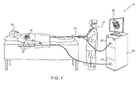
- FIG. 1 is a schematic pictorial illustration of a system for ablation of tissue in the heart, in accordance with an embodiment of the present invention
- FIG. 2 is a schematic sectional view of a heart showing insertion of a catheter into the left atrium, in accordance with an embodiment of the present invention
- FIGS. 3A and 3B are schematic side and sectional views, respectively, of a catheter, in accordance with an embodiment of the present invention.
- FIGS. 4A and 4B are schematic side and sectional views, respectively, of a catheter, in accordance with another embodiment of the present invention.
- Lasso catheters may be used for ablating tissue along an arc surrounding an anatomical structure, such as the ostium of a pulmonary vein.
- the lasso is generally made thin and flexible, for purposes of maneuverability, with large ring electrodes to minimize electrical resistance.
- Embodiments of the present invention that are described hereinbelow provide probes, such as catheters, with improved lasso-type structures to facilitate maneuvering and positioning of the structure in the heart.
- catheters can be used to produce curved ablation paths, as well as sensing electrical activity at points along a curve.
- a catheter comprises an insertion shaft having a longitudinal axis.
- a resilient end section, with electrodes disposed along its length, is fixed to the distal end of the insertion shaft.
- This end section is formed so as to define, when unconstrained, an arc oriented obliquely relative to the longitudinal axis of the insertion shaft and having a center of curvature on the axis.
- oblique in the context of the present patent application and in the claims, means that the plane in space that best fits the arc is angled relative to the shaft axis. The angle between the plane and the axis is typically at least 45°, and in the embodiments shown below is approximately 90°.
- An operator inserts the catheter into a body cavity, such as a heart chamber, and advances the distal end of the catheter axially toward a tissue in the body, such as the inner heart wall.
- a body cavity such as a heart chamber
- axial refers to the direction parallel to the longitudinal axis of the insertion shaft.
- the arc may have a helical form, whereby the distal tip of the end section protrudes axially in the distal direction relative to the base of the end section, which connects to the insertion shaft (i.e., when the end section is unconstrained, the tip is slightly ahead of the base).
- the helical form is compressed axially and thus flattened as the end section is advanced against the tissue, so that there is positive pressure between each of the electrodes and the tissue.
- the operator rotates the insertion shaft about its axis, thus causing the arc to describe an annular path on the tissue while the electrodes contact the tissue. Because the arc is centered on the axis, simple rotation of the shaft is sufficient to engender this annular motion, typically without the need for additional manipulation or steering of the catheter.
- the operator can cause the end section to trace an annular path around an anatomical feature, such as the ostium of a pulmonary vein in the left atrium.
- the operator may apply energy, such as radio frequency (RF) electrical current, through the electrodes so as to ablate the tissue along this annular path.
- RF radio frequency
- FIG. 1 is a schematic pictorial illustration of a system 20 for ablation of tissue in a heart 26 of a patient 28 , in accordance with an embodiment of the present invention.
- An operator 22 such as a cardiologist, inserts a catheter 24 through the vascular system of patient 28 so that the distal end of the catheter enters a chamber of the patient's heart.
- Operator 22 advances the catheter so that the end section of the catheter engages endocardial tissue at a desired location or locations, as shown in the figures that follow.
- Catheter 24 is connected by a suitable connector at its proximal end to a console 30 .
- the console comprises a RF generator 36 for applying RF energy through electrodes on the end section of the catheter in order to ablate the tissue contacted by the distal section.
- catheter 24 may be used for other diagnostic and/or therapeutic functions, such as intracardiac electrical mapping or other types of ablation therapy.
- system 20 uses magnetic position sensing to determine position coordinates of the end section of the catheter inside heart 26 .
- a driver circuit 34 in console 30 drives field generators 32 to generate magnetic fields within the body of patient 28 .
- field generators 32 comprise coils, which are placed below the patient's torso at known positions external to the body. These coils generate magnetic fields in a predefined working volume that contains heart 26 .
- One or more magnetic field sensors within the end section of catheter 24 (as shown in FIG. 3 ) generate electrical signals in response to these magnetic fields.
- the console processes these signals in order to determine the position (location and/or orientation) coordinates of the end section of catheter 24 , and possibly also the deformation of the end section, as explained below.
- Console 30 may use the coordinates in driving a display 38 to show the location and status of the catheter. This method of position sensing and processing is described in detail, for example, in PCT International Publication WO 96/05768, whose disclosure is incorporated herein by reference, and is implemented in the CARTOTM system produced by Biosense Webster Inc. (Diamond Bar, Calif.).
- system 20 may comprise an automated mechanism (not shown) for maneuvering and operating catheter 24 within the body of patient 28 .
- Such mechanisms are typically capable of controlling both the longitudinal motion (advance/retract) and the rotation of catheter 24 .
- console 30 generates a control input for controlling the motion of the catheter based on the signals provided by the position sensing system.
- FIG. 1 shows a particular system configuration
- the methods described hereinbelow may be applied using position transducers of other types, such as impedance-based or ultrasonic position sensors.
- position transducer refers to an element mounted on or in catheter 24 that causes console 30 to receive signals indicative of the coordinates of the element.
- the position transducer may thus comprise a receiver in the catheter, which generates a position signal to the control unit based on energy received by the transducer; or it may comprise a transmitter, emitting energy that is sensed by a receiver external to the probe.
- the methods described hereinbelow may similarly be applied in mapping and measurement applications using not only catheters, but also probes of other types, both in the heart and in other body organs and regions.
- FIG. 2 is a schematic sectional view of heart 26 , showing insertion of catheter 24 into the heart, in accordance with an embodiment of the present invention.
- the operator first passes a sheath 40 percutaneously through the vascular system and into right atrium 44 of the heart through ascending vena cava 42 .
- the sheath penetrates through interatrial septum 48 , typically via the fossa ovalis, into left atrium 46 .
- Catheter 24 is then inserted through the sheath until an end section 52 of the catheter passes out of the distal opening at the end of the sheath into the left atrium, as shown in the figure.
- the end section is formed so as to define an arc when unconstrained, as is shown and described in greater detail hereinbelow.
- Operator 22 aligns the longitudinal axis of sheath 40 (and of catheter 24 ) inside left atrium 46 with the axis of one of pulmonary veins 50 .
- the operator may carry out this alignment using the position sensing methods described above, along with a pre-acquired map or image of heart 26 .
- the alignment may be performed under fluoroscopic or other means of visualization.
- the operator advances end section 52 of the catheter toward the target pulmonary vein so that the arc contacts the ostium, so that the end section either partly or fully surrounds the vein (depending on the angle subtended by the arc).
- the operator then rotates the catheter about its axis within the sheath so that the end section traces an annular path around the circumference of the vein. Meanwhile, the operator actuates RF generator 36 to ablate the tissue along the path.
- the operator may shift the sheath and catheter and repeat the procedure around one or more of the other pulmonary veins.
- the above procedures may be carried out without the use of any steering mechanism in catheter 24 : Due to the curved shape of the catheter, only advancement/retraction and rotation of the catheter are required. The absence of an internal steering mechanism reduces the size and cost of the catheter relative to devices that are known in the art. As noted earlier, the above procedures may be carried out by an automated mechanism, rather than manually by the operator as illustrated in FIG. 1 .
- catheter 24 may contain a steering mechanism (not shown), which enables operator 22 to straighten the joints of end section 52 .
- the operator may manipulate catheter 24 in order to trace (and possibly ablate) other sorts of paths or to sense or ablate tissue at specific, discrete points in the heart wall, either in left atrium 46 or elsewhere.
- FIG. 3A is a side view
- FIG. 3B is a cross-sectional view taken along a line IIIB-IIIB in FIG. 3A
- the catheter comprises an insertion shaft 54 , which connects at its distal end to the base of end section 52 .
- the Z-axis in these figures is taken to be the longitudinal axis of the insertion shaft, as illustrated by a dashed line in FIG. 3A .
- End section 52 is oriented roughly in the X-Y plane but has a helical form so that the distal tip of section 52 protrudes axially (along the Z-axis) in the distal direction (to the right in FIG. 3A ).
- Shaft 54 and end section 52 typically comprise an outer shell made from a suitable flexible biocompatible material, such as polyurethane, having a diameter around 2-3 mm, with internal wires and tubing as required.
- a suitable flexible biocompatible material such as polyurethane
- the size of the shaft is 7 Fr (about 2.3 mm diameter), while the end section is of the same or slightly larger size (such as 7.5 Fr).
- the shaft is 7 Fr, while the end section has a diameter between 1 and 2.5 mm.
- End section 52 is formed as a partial lasso, i.e., as a preformed arcuate structure, which is centered on the axis of shaft 54 and loops through considerably less than 360°, and typically less than 270°. In the pictured embodiment, for example, the catheter ends in a “half-lasso” arc of about 180°. This sort of shape makes the end section easier to maneuver and position accurately.
- the radius of curvature of end section 52 when unconstrained, is typically between 7.5 mm and 15 mm.
- the arc structure is resilient and, possibly, slightly helical, when end section 52 is positioned in the heart (half surrounding the ostium of a pulmonary vein, for example), and insertion shaft 54 is advanced distally, the end section will press against the heart tissue over the entire length of the arc, thus facilitating good tissue contact.
- the arcuate, helical shape of end section 52 may be maintained, for example, by incorporating a thin strut made from a shape memory material, such as Nitinol, in the desired shape (not shown in the figures) within the end section.
- the strut is typically made sufficiently flexible to permit the end section to straighten during insertion through sheath 40 , and then to resume its arcuate form when it is unconstrained inside the heart chamber.
- the strut is designed so that an axial force of 5 grams or greater is required to flatten the helical shape so that the entire length of the arcuate end section presses against the tissue.
- End section 52 comprises an array of electrodes along its length, including, in this example, a tip electrode 56 extending over the distal tip of the end section and proximal electrodes 58 distributed along the end section.
- the electrodes have a width between 1 mm and 4 mm, and are spaced between 1 mm and 10 mm apart.
- the electrodes are connected to the connector at the proximal end of catheter 24 by wires (not shown) running through the catheter.
- the end section may include only ring electrodes, without a tip electrode.
- the end section may include smaller “bump” electrodes, as described in the above-mentioned U.S. patent application Ser. No. 12/345,720. In any of these configurations, the electrodes may be used for sensing and/or ablation. In order to ablate an entire annulus around a pulmonary vein, for example, catheter 24 may be rotated (“clocked”) about its axis, as noted above.
- electrodes 56 and 58 may have perforations for irrigation.
- Perforations of this type are described and shown in U.S. patent application Ser. No. 12/345,720.
- the perforations are coupled to a lumen (not shown) in end section 52 , which carries irrigation fluid from shaft 54 to the electrodes and to the tissue surrounding them.
- the pressure of irrigation fluid tends to be lower at the distal end of the end section than at the proximal.
- the irrigation holes in the distal electrodes may be relatively larger and/or more numerous than in the proximal electrodes.
- end section 52 comprises an internal steering mechanism (not shown), which can be operated to straighten the joints of the end section and to bring tip electrode 56 alone into contact with the tissue surface.
- the steering mechanism may comprise one or more pull-wires, which run through a lumen in the catheter, as is known in the art.
- the catheter may contain multiple lumens, for pull-wires and the strut mentioned above, for irrigation fluid, and for electrical wires connected to the electrodes and position transducers.
- the tip electrode can be brought into contact with the point and actuated by itself.
- catheter 24 can be used for both individual points and for curved ablation and/or sensing paths, providing enhanced utility and versatility in carrying out different sorts of procedures.
- Catheter 24 may also include one of more position transducers, such as positions sensors 60 and 62 shown in FIGS. 3A and 3B .
- sensors 60 and 62 comprise coils, which output position signals in response to the magnetic fields of field generators 32 ( FIG. 1 ).
- sensor 60 may comprise three coils, which give full location and orientation information with regard to the base of end section 52
- sensors 62 comprise each comprise a single coil, giving location and partial orientation information.
- This sort of arrangement is described further in the above-mentioned U.S. Patent Application Publication 2005/0033135. It enables console 30 to track both the base location and the deformation of the end section, so that the operator can verify that the end section is properly located and in good contact with the tissue.
- other types of position transducers and sensing configurations may be used in catheter 24 and system 20 .
- FIGS. 4A and 4B schematically illustrate the distal portion of a catheter 70 , in accordance with another embodiment of the present invention.
- FIG. 4A is a side view
- FIG. 4B is a cross-sectional view taken along a line IVB-IVB in FIG. 4A .
- Certain elements of catheter 70 such as insertion shaft 54 and electrodes 56 and 58 , are similar to the corresponding elements of catheter 24 , as described above, and are therefore marked with the same numbers.
- Catheter 70 may have other features similar to those of catheter 24 , such as internal struts, steering elements, position transducers, and various electrode types and irrigation, but these features have been omitted from the figures and from the present description for the sake of simplicity and brevity.
- Catheter 70 differs from catheter 24 in that an arcuate end section 72 of catheter 70 is formed as a full (or nearly full) loop, subtending more than 300°, and possibly the full 360°. Therefore, end section 72 is capable of covering an entire annular ablation or sensing path with little or no rotation of shaft 54 .
- End section 72 like end section 52 of catheter 24 , is centered on the axis of shaft 54 and helical in shape. These features make the end section easier to position in the desired anatomical location and facilitate good contact between electrodes 58 and the target tissue over the entire length of the end section.
Abstract
Description
Claims (21)
Priority Applications (11)
| Application Number | Priority Date | Filing Date | Title |
|---|---|---|---|
| US12/649,417 US8608735B2 (en) | 2009-12-30 | 2009-12-30 | Catheter with arcuate end section |
| IL227721A IL227721A (en) | 2009-12-30 | 2010-12-20 | Catheter with arcuate end section |
| IL210131A IL210131A (en) | 2009-12-30 | 2010-12-20 | Catheter with arcuate end section |
| CA2726334A CA2726334C (en) | 2009-12-30 | 2010-12-22 | Catheter with arcuate end section |
| AU2010257390A AU2010257390B2 (en) | 2009-12-30 | 2010-12-22 | Catheter with arcuate end section |
| JP2010292039A JP5836590B2 (en) | 2009-12-30 | 2010-12-28 | Catheter having an arcuate end portion |
| EP10252246.3A EP2340765B1 (en) | 2009-12-30 | 2010-12-29 | Catheter with arcuate end section |
| EP16175313.2A EP3111839B1 (en) | 2009-12-30 | 2010-12-29 | Catheter with arcuate end section |
| EP12185274A EP2537465A1 (en) | 2009-12-30 | 2010-12-29 | Catheter with arcuate end section and position transducer |
| CN201010624677.4A CN102113907B (en) | 2009-12-30 | 2010-12-30 | There is the conduit of arcuate end section |
| IL245262A IL245262A (en) | 2009-12-30 | 2016-04-20 | Catheter with arcuate end section |
Applications Claiming Priority (1)
| Application Number | Priority Date | Filing Date | Title |
|---|---|---|---|
| US12/649,417 US8608735B2 (en) | 2009-12-30 | 2009-12-30 | Catheter with arcuate end section |
Publications (2)
| Publication Number | Publication Date |
|---|---|
| US20110160719A1 US20110160719A1 (en) | 2011-06-30 |
| US8608735B2 true US8608735B2 (en) | 2013-12-17 |
Family
ID=43857788
Family Applications (1)
| Application Number | Title | Priority Date | Filing Date |
|---|---|---|---|
| US12/649,417 Active 2032-03-15 US8608735B2 (en) | 2009-12-30 | 2009-12-30 | Catheter with arcuate end section |
Country Status (7)
| Country | Link |
|---|---|
| US (1) | US8608735B2 (en) |
| EP (3) | EP2340765B1 (en) |
| JP (1) | JP5836590B2 (en) |
| CN (1) | CN102113907B (en) |
| AU (1) | AU2010257390B2 (en) |
| CA (1) | CA2726334C (en) |
| IL (3) | IL210131A (en) |
Cited By (35)
| Publication number | Priority date | Publication date | Assignee | Title |
|---|---|---|---|---|
| US20120165667A1 (en) * | 2010-12-22 | 2012-06-28 | Andres Claudio Altmann | Lasso catheter with ultrasound transducer |
| US20130158539A1 (en) * | 2009-12-11 | 2013-06-20 | Biosense Webster (Israel), Ltd. | Pre-formed curved ablation catheter |
| US20150088121A1 (en) * | 2010-08-31 | 2015-03-26 | Cook Medical Technologies Llc | Ablation Overtube |
| USD753302S1 (en) * | 2015-02-11 | 2016-04-05 | Baylis Medical Company Inc. | Electrosurgical device with a curve |
| EP3023069A1 (en) | 2014-11-20 | 2016-05-25 | Biosense Webster (Israel) Ltd. | Catheter with soft distal tip for mapping and ablating tubular region |
| WO2017024107A1 (en) * | 2015-08-06 | 2017-02-09 | Greenville Health System | Devices and methods for mapping cardiac arrhythmia |
| US9724170B2 (en) | 2012-08-09 | 2017-08-08 | University Of Iowa Research Foundation | Catheters, catheter systems, and methods for puncturing through a tissue structure and ablating a tissue region |
| US9987081B1 (en) | 2017-04-27 | 2018-06-05 | Iowa Approach, Inc. | Systems, devices, and methods for signal generation |
| US9999465B2 (en) | 2014-10-14 | 2018-06-19 | Iowa Approach, Inc. | Method and apparatus for rapid and safe pulmonary vein cardiac ablation |
| EP3342364A2 (en) | 2016-12-28 | 2018-07-04 | Biosense Webster (Israel) Ltd. | Catheter with tapered support member for variable arcuate distal assembly |
| US10130423B1 (en) | 2017-07-06 | 2018-11-20 | Farapulse, Inc. | Systems, devices, and methods for focal ablation |
| US10172673B2 (en) | 2016-01-05 | 2019-01-08 | Farapulse, Inc. | Systems devices, and methods for delivery of pulsed electric field ablative energy to endocardial tissue |
| US10322286B2 (en) | 2016-01-05 | 2019-06-18 | Farapulse, Inc. | Systems, apparatuses and methods for delivery of ablative energy to tissue |
| US10433906B2 (en) | 2014-06-12 | 2019-10-08 | Farapulse, Inc. | Method and apparatus for rapid and selective transurethral tissue ablation |
| US10507302B2 (en) | 2016-06-16 | 2019-12-17 | Farapulse, Inc. | Systems, apparatuses, and methods for guide wire delivery |
| US10512505B2 (en) | 2018-05-07 | 2019-12-24 | Farapulse, Inc. | Systems, apparatuses and methods for delivery of ablative energy to tissue |
| US10517672B2 (en) | 2014-01-06 | 2019-12-31 | Farapulse, Inc. | Apparatus and methods for renal denervation ablation |
| US10617867B2 (en) | 2017-04-28 | 2020-04-14 | Farapulse, Inc. | Systems, devices, and methods for delivery of pulsed electric field ablative energy to esophageal tissue |
| US10624693B2 (en) | 2014-06-12 | 2020-04-21 | Farapulse, Inc. | Method and apparatus for rapid and selective tissue ablation with cooling |
| US10625080B1 (en) | 2019-09-17 | 2020-04-21 | Farapulse, Inc. | Systems, apparatuses, and methods for detecting ectopic electrocardiogram signals during pulsed electric field ablation |
| US10660702B2 (en) | 2016-01-05 | 2020-05-26 | Farapulse, Inc. | Systems, devices, and methods for focal ablation |
| US10687892B2 (en) | 2018-09-20 | 2020-06-23 | Farapulse, Inc. | Systems, apparatuses, and methods for delivery of pulsed electric field ablative energy to endocardial tissue |
| US10842572B1 (en) | 2019-11-25 | 2020-11-24 | Farapulse, Inc. | Methods, systems, and apparatuses for tracking ablation devices and generating lesion lines |
| US10893905B2 (en) | 2017-09-12 | 2021-01-19 | Farapulse, Inc. | Systems, apparatuses, and methods for ventricular focal ablation |
| US10918832B2 (en) | 2017-03-27 | 2021-02-16 | Biosense Webster (Israel) Ltd | Catheter with improved loop contraction and greater contraction displacement |
| EP3808266A1 (en) | 2019-10-18 | 2021-04-21 | Biosense Webster (Israel) Ltd | Verifying proper withdrawal of catheter into sheath |
| US11020180B2 (en) | 2018-05-07 | 2021-06-01 | Farapulse, Inc. | Epicardial ablation catheter |
| US11033236B2 (en) | 2018-05-07 | 2021-06-15 | Farapulse, Inc. | Systems, apparatuses, and methods for filtering high voltage noise induced by pulsed electric field ablation |
| EP3842003A1 (en) | 2019-12-27 | 2021-06-30 | Biosense Webster (Israel) Ltd | Device and method of determining location of sheath using electromagnetic sensors on sheath |
| US11065047B2 (en) | 2019-11-20 | 2021-07-20 | Farapulse, Inc. | Systems, apparatuses, and methods for protecting electronic components from high power noise induced by high voltage pulses |
| US11259869B2 (en) | 2014-05-07 | 2022-03-01 | Farapulse, Inc. | Methods and apparatus for selective tissue ablation |
| USD963855S1 (en) * | 2019-09-04 | 2022-09-13 | Boston Scientific Medical Device Limited | Electrosurgical device with a curve |
| US11497541B2 (en) | 2019-11-20 | 2022-11-15 | Boston Scientific Scimed, Inc. | Systems, apparatuses, and methods for protecting electronic components from high power noise induced by high voltage pulses |
| EP4115832A1 (en) | 2021-07-09 | 2023-01-11 | Biosense Webster (Israel) Ltd. | Pulsed field ablation catheter |
| EP4338695A1 (en) | 2022-09-11 | 2024-03-20 | Biosense Webster (Israel) Ltd. | System for combined ablation modalities |
Families Citing this family (33)
| Publication number | Priority date | Publication date | Assignee | Title |
|---|---|---|---|---|
| US6702811B2 (en) | 1999-04-05 | 2004-03-09 | Medtronic, Inc. | Ablation catheter assembly with radially decreasing helix and method of use |
| US20140018880A1 (en) | 2002-04-08 | 2014-01-16 | Medtronic Ardian Luxembourg S.A.R.L. | Methods for monopolar renal neuromodulation |
| US8774913B2 (en) | 2002-04-08 | 2014-07-08 | Medtronic Ardian Luxembourg S.A.R.L. | Methods and apparatus for intravasculary-induced neuromodulation |
| US7653438B2 (en) | 2002-04-08 | 2010-01-26 | Ardian, Inc. | Methods and apparatus for renal neuromodulation |
| US8600472B2 (en) * | 2008-12-30 | 2013-12-03 | Biosense Webster (Israel), Ltd. | Dual-purpose lasso catheter with irrigation using circumferentially arranged ring bump electrodes |
| US8475450B2 (en) | 2008-12-30 | 2013-07-02 | Biosense Webster, Inc. | Dual-purpose lasso catheter with irrigation |
| WO2010148380A1 (en) * | 2009-06-19 | 2010-12-23 | Medtronic, Inc. | Arcuate introducer |
| US8920415B2 (en) * | 2009-12-16 | 2014-12-30 | Biosense Webster (Israel) Ltd. | Catheter with helical electrode |
| TWI556849B (en) | 2010-10-21 | 2016-11-11 | 美敦力阿福盧森堡公司 | Catheter apparatus for renal neuromodulation |
| MX2013004235A (en) | 2010-10-25 | 2013-05-30 | Medtronic Ardian Luxembourg | Catheter apparatuses having multi-electrode arrays for renal neuromodulation and associated systems and methods. |
| US9211094B2 (en) * | 2010-12-10 | 2015-12-15 | Biosense Webster (Israel), Ltd. | System and method for detection of metal disturbance based on contact force measurement |
| CN103339917B (en) | 2011-01-31 | 2016-11-09 | 立志凯株式会社 | Illuminator |
| US9220433B2 (en) * | 2011-06-30 | 2015-12-29 | Biosense Webster (Israel), Ltd. | Catheter with variable arcuate distal section |
| US9662169B2 (en) | 2011-07-30 | 2017-05-30 | Biosense Webster (Israel) Ltd. | Catheter with flow balancing valve |
| US8876726B2 (en) * | 2011-12-08 | 2014-11-04 | Biosense Webster (Israel) Ltd. | Prevention of incorrect catheter rotation |
| CN102579031B (en) * | 2012-01-19 | 2014-10-01 | 洪浪 | Right ventricular outflow tract mapping and angiographic catheter and preparation method of angiographic catheter |
| US9314299B2 (en) * | 2012-03-21 | 2016-04-19 | Biosense Webster (Israel) Ltd. | Flower catheter for mapping and ablating veinous and other tubular locations |
| US9439722B2 (en) * | 2012-05-09 | 2016-09-13 | Biosense Webster (Israel) Ltd. | Ablation targeting nerves in or near the inferior vena cava and/or abdominal aorta for treatment of hypertension |
| US9717555B2 (en) * | 2012-05-14 | 2017-08-01 | Biosense Webster (Israel), Ltd. | Catheter with helical end section for vessel ablation |
| ES2614272T3 (en) | 2012-05-11 | 2017-05-30 | Medtronic Ardian Luxembourg S.à.r.l. | Multiple electrode catheter assemblies for renal neuromodulation and associated systems and methods |
| US9044575B2 (en) | 2012-10-22 | 2015-06-02 | Medtronic Adrian Luxembourg S.a.r.l. | Catheters with enhanced flexibility and associated devices, systems, and methods |
| US9095321B2 (en) | 2012-11-21 | 2015-08-04 | Medtronic Ardian Luxembourg S.A.R.L. | Cryotherapeutic devices having integral multi-helical balloons and methods of making the same |
| CN103830000B (en) * | 2012-11-23 | 2016-03-02 | 四川锦江电子科技有限公司 | Controllable bending open irrigated ablation catheters |
| US9023036B2 (en) * | 2012-12-07 | 2015-05-05 | Biosense Webster (Israel) Ltd. | Lasso catheter with tip electrode |
| US9474850B2 (en) | 2012-12-11 | 2016-10-25 | Biosense Webster (Israel) Ltd. | Lasso catheter with guide wire |
| US9179974B2 (en) | 2013-03-15 | 2015-11-10 | Medtronic Ardian Luxembourg S.A.R.L. | Helical push wire electrode |
| WO2014189794A1 (en) | 2013-05-18 | 2014-11-27 | Medtronic Ardian Luxembourg S.A.R.L. | Neuromodulation catheters with shafts for enhanced flexibility and control and associated devices, systems, and methods |
| US20150073515A1 (en) | 2013-09-09 | 2015-03-12 | Medtronic Ardian Luxembourg S.a.r.I. | Neuromodulation Catheter Devices and Systems Having Energy Delivering Thermocouple Assemblies and Associated Methods |
| EP4059563B1 (en) | 2014-01-27 | 2023-09-27 | Medtronic Ireland Manufacturing Unlimited Company | Neuromodulation catheters having jacketed neuromodulation elements and related devices |
| CN106232043B (en) | 2014-04-24 | 2019-07-23 | 美敦力阿迪安卢森堡有限公司 | Nerve modulation conduit and relevant system and method with braiding axle |
| KR101672879B1 (en) * | 2014-04-29 | 2016-11-07 | 재단법인 아산사회복지재단 | Catheter assembly |
| CN107405099B (en) * | 2015-05-11 | 2021-02-09 | 圣犹达医疗用品心脏病学部门有限公司 | High density mapping and ablation catheter |
| US20220095947A1 (en) * | 2020-09-29 | 2022-03-31 | Biosense Webster (Israel) Ltd. | Circular navigation catheter with surface mounted inductive navigation sensors |
Citations (211)
| Publication number | Priority date | Publication date | Assignee | Title |
|---|---|---|---|---|
| US3971364A (en) | 1975-05-16 | 1976-07-27 | Nasa | Catheter tip force transducer for cardiovascular research |
| US4488561A (en) | 1983-06-27 | 1984-12-18 | Medtronic, Inc. | Pacing lead with insertable memory coil |
| US4764114A (en) | 1986-01-13 | 1988-08-16 | Foster-Miller, Inc. | Analysis system |
| US4856993A (en) | 1985-03-29 | 1989-08-15 | Tekscan, Inc. | Pressure and contact sensor system for measuring dental occlusion |
| US4917102A (en) | 1988-09-14 | 1990-04-17 | Advanced Cardiovascular Systems, Inc. | Guidewire assembly with steerable adjustable tip |
| US4917104A (en) | 1988-06-10 | 1990-04-17 | Telectronics Pacing Systems, Inc. | Electrically insulated "J" stiffener wire |
| US5263493A (en) | 1992-02-24 | 1993-11-23 | Boaz Avitall | Deflectable loop electrode array mapping and ablation catheter for cardiac chambers |
| US5368564A (en) | 1992-12-23 | 1994-11-29 | Angeion Corporation | Steerable catheter |
| US5391199A (en) | 1993-07-20 | 1995-02-21 | Biosense, Inc. | Apparatus and method for treating cardiac arrhythmias |
| US5487757A (en) | 1993-07-20 | 1996-01-30 | Medtronic Cardiorhythm | Multicurve deflectable catheter |
| US5499542A (en) | 1994-04-22 | 1996-03-19 | Westinghouse Electric Corporation | Diametral force sensor |
| US5558091A (en) | 1993-10-06 | 1996-09-24 | Biosense, Inc. | Magnetic determination of position and orientation |
| US5563354A (en) | 1995-04-03 | 1996-10-08 | Force Imaging Technologies, Inc. | Large area sensing cell |
| US5643197A (en) | 1993-12-21 | 1997-07-01 | Angeion Corporation | Fluid cooled and perfused tip for a catheter |
| US5662124A (en) | 1996-06-19 | 1997-09-02 | Wilk Patent Development Corp. | Coronary artery by-pass method |
| US5673695A (en) | 1995-08-02 | 1997-10-07 | Ep Technologies, Inc. | Methods for locating and ablating accessory pathways in the heart |
| US5680860A (en) | 1994-07-07 | 1997-10-28 | Cardiac Pathways Corporation | Mapping and/or ablation catheter with coilable distal extremity and method for using same |
| US5685878A (en) | 1995-11-13 | 1997-11-11 | C.R. Bard, Inc. | Snap fit distal assembly for an ablation catheter |
| US5730127A (en) | 1993-12-03 | 1998-03-24 | Avitall; Boaz | Mapping and ablation catheter system |
| US5769843A (en) | 1996-02-20 | 1998-06-23 | Cormedica | Percutaneous endomyocardial revascularization |
| US5820591A (en) | 1990-02-02 | 1998-10-13 | E. P. Technologies, Inc. | Assemblies for creating compound curves in distal catheter regions |
| US5826576A (en) | 1996-08-08 | 1998-10-27 | Medtronic, Inc. | Electrophysiology catheter with multifunction wire and method for making |
| US5836894A (en) | 1992-12-21 | 1998-11-17 | Artann Laboratories | Apparatus for measuring mechanical parameters of the prostate and for imaging the prostate using such parameters |
| US5860974A (en) | 1993-07-01 | 1999-01-19 | Boston Scientific Corporation | Heart ablation catheter with expandable electrode and method of coupling energy to an electrode on a catheter shaft |
| US5865815A (en) | 1997-04-25 | 1999-02-02 | Contimed, Inc. | Prostatic obstruction relief catheter |
| US5871523A (en) | 1993-10-15 | 1999-02-16 | Ep Technologies, Inc. | Helically wound radio-frequency emitting electrodes for creating lesions in body tissue |
| US5902248A (en) | 1996-11-06 | 1999-05-11 | Millar Instruments, Inc. | Reduced size catheter tip measurement device |
| US5916147A (en) | 1997-09-22 | 1999-06-29 | Boury; Harb N. | Selectively manipulable catheter |
| US5938694A (en) | 1993-11-10 | 1999-08-17 | Medtronic Cardiorhythm | Electrode array catheter |
| US5944022A (en) | 1997-04-28 | 1999-08-31 | American Cardiac Ablation Co. Inc. | Catheter positioning system |
| US5964757A (en) | 1997-09-05 | 1999-10-12 | Cordis Webster, Inc. | Steerable direct myocardial revascularization catheter |
| US5974320A (en) | 1997-05-21 | 1999-10-26 | Telefonaktiebolaget Lm Ericsson (Publ) | Providing a neighborhood zone within a mobile telecommunications network |
| US5983126A (en) | 1995-11-22 | 1999-11-09 | Medtronic, Inc. | Catheter location system and method |
| US6002955A (en) | 1996-11-08 | 1999-12-14 | Medtronic, Inc. | Stabilized electrophysiology catheter and method for use |
| DE19750441C2 (en) | 1997-11-14 | 2000-01-27 | Markus Becker | Device for detecting and controlling postures for therapeutic use in a sitting position |
| US6048329A (en) | 1996-12-19 | 2000-04-11 | Ep Technologies, Inc. | Catheter distal assembly with pull wires |
| US6063022A (en) | 1997-01-03 | 2000-05-16 | Biosense, Inc. | Conformal catheter |
| US6064902A (en) | 1998-04-16 | 2000-05-16 | C.R. Bard, Inc. | Pulmonary vein ablation catheter |
| US6123699A (en) | 1997-09-05 | 2000-09-26 | Cordis Webster, Inc. | Omni-directional steerable catheter |
| US6171277B1 (en) | 1997-12-01 | 2001-01-09 | Cordis Webster, Inc. | Bi-directional control handle for steerable catheter |
| US6177792B1 (en) | 1996-03-26 | 2001-01-23 | Bisense, Inc. | Mutual induction correction for radiator coils of an objects tracking system |
| US6183463B1 (en) | 1997-12-01 | 2001-02-06 | Cordis Webster, Inc. | Bidirectional steerable cathether with bidirectional control handle |
| US6198974B1 (en) | 1998-08-14 | 2001-03-06 | Cordis Webster, Inc. | Bi-directional steerable catheter |
| US6201387B1 (en) | 1997-10-07 | 2001-03-13 | Biosense, Inc. | Miniaturized position sensor having photolithographic coils for tracking a medical probe |
| US6203493B1 (en) | 1996-02-15 | 2001-03-20 | Biosense, Inc. | Attachment with one or more sensors for precise position determination of endoscopes |
| US6216027B1 (en) | 1997-08-01 | 2001-04-10 | Cardiac Pathways Corporation | System for electrode localization using ultrasound |
| US6226542B1 (en) | 1998-07-24 | 2001-05-01 | Biosense, Inc. | Three-dimensional reconstruction of intrabody organs |
| US6239724B1 (en) | 1997-12-30 | 2001-05-29 | Remon Medical Technologies, Ltd. | System and method for telemetrically providing intrabody spatial position |
| US6241724B1 (en) | 1993-10-19 | 2001-06-05 | Ep Technologies, Inc. | Systems and methods for creating lesions in body tissue using segmented electrode assemblies |
| US6267781B1 (en) | 1998-08-31 | 2001-07-31 | Quantum Therapeutics Corp. | Medical device and methods for treating valvular annulus |
| US6272371B1 (en) | 1997-01-03 | 2001-08-07 | Biosense Inc. | Bend-responsive catheter |
| US6272672B1 (en) | 1995-09-06 | 2001-08-07 | Melvin E. Conway | Dataflow processing with events |
| US6301496B1 (en) | 1998-07-24 | 2001-10-09 | Biosense, Inc. | Vector mapping of three-dimensionally reconstructed intrabody organs and method of display |
| US20010047133A1 (en) | 1998-08-02 | 2001-11-29 | Super Dimension Ltd. | Imaging device with magnetically permeable compensator |
| US20010047129A1 (en) | 1999-05-13 | 2001-11-29 | Hall Andrew F. | Medical devices adapted for magnetic navigation with magnetic fields and gradients |
| US6332089B1 (en) | 1996-02-15 | 2001-12-18 | Biosense, Inc. | Medical procedures and apparatus using intrabody probes |
| US6335617B1 (en) | 1996-05-06 | 2002-01-01 | Biosense, Inc. | Method and apparatus for calibrating a magnetic field generator |
| US20020022839A1 (en) * | 1999-04-05 | 2002-02-21 | Medtronic, Inc. | Ablation catheter and method for isolating a pulmonary vein |
| EP1181896A1 (en) | 2000-08-21 | 2002-02-27 | Biosense Webster, Inc. | Ablation catheter with cooled linear electrode |
| US6371955B1 (en) | 1999-08-10 | 2002-04-16 | Biosense Webster, Inc. | Atrial branding iron catheter and a method for treating atrial fibrillation |
| US20020065455A1 (en) | 1995-01-24 | 2002-05-30 | Shlomo Ben-Haim | Medical diagnosis, treatment and imaging systems |
| US20020068866A1 (en) | 2000-08-14 | 2002-06-06 | Zikorus Arthur W. | Method and apparatus for positioning a catheter relative to an anatomical junction |
| US6436059B1 (en) | 2000-09-12 | 2002-08-20 | Claudio I. Zanelli | Detection of imd contact and alignment based on changes in frequency response characteristics |
| US6456864B1 (en) | 1994-10-11 | 2002-09-24 | Ep Technologies, Inc. | Systems and methods for guiding movable electrode elements within multiple-electrode structures |
| US6468260B1 (en) | 1999-05-07 | 2002-10-22 | Biosense Webster, Inc. | Single gear drive bidirectional control handle for steerable catheter |
| US20020165461A1 (en) | 2001-05-02 | 2002-11-07 | Hayzelden Robert C. | Steerable catheter with shaft support system for resisting axial compressive loads |
| US6484118B1 (en) | 2000-07-20 | 2002-11-19 | Biosense, Inc. | Electromagnetic position single axis system |
| US20020193781A1 (en) | 2001-06-14 | 2002-12-19 | Loeb Marvin P. | Devices for interstitial delivery of thermal energy into tissue and methods of use thereof |
| US6522933B2 (en) | 2001-03-30 | 2003-02-18 | Biosense, Webster, Inc. | Steerable catheter with a control handle having a pulley mechanism |
| US6551302B1 (en) | 1997-09-24 | 2003-04-22 | Michael J. Rosinko | Steerable catheter with tip alignment and surface contact detector |
| US6574492B1 (en) | 1996-01-08 | 2003-06-03 | Biosense, Inc. | Catheter having multiple arms with electrode and position sensor |
| US20030105453A1 (en) | 2001-05-03 | 2003-06-05 | Stewart Mark T. | Porous medical catheter and methods of manufacture |
| US20030120195A1 (en) | 1998-01-13 | 2003-06-26 | Lumend, Inc. | Re-entry catheter |
| US6584856B1 (en) | 2000-08-30 | 2003-07-01 | William J. Biter | Method of sensing strain in a material by driving an embedded magnetoelastic film-coated wire to saturation |
| US20030130615A1 (en) | 2000-03-23 | 2003-07-10 | Scimed Life Systems, Inc. | Pressure sensor for therapeutic delivery device and method |
| US6592581B2 (en) | 1998-05-05 | 2003-07-15 | Cardiac Pacemakers, Inc. | Preformed steerable catheter with movable outer sleeve and method for use |
| US6602242B1 (en) | 1997-12-01 | 2003-08-05 | Biosense Webster, Inc. | Irrigated tip catheter |
| US20030158494A1 (en) | 2002-02-19 | 2003-08-21 | Roger Dahl | Apparatus and method for sensing spatial displacement in a heart |
| US6612992B1 (en) | 2000-03-02 | 2003-09-02 | Acuson Corp | Medical diagnostic ultrasound catheter and method for position determination |
| US6618612B1 (en) | 1996-02-15 | 2003-09-09 | Biosense, Inc. | Independently positionable transducers for location system |
| US20030216722A1 (en) | 2002-05-20 | 2003-11-20 | Scimed Life Systems, Inc. | Systems and methods for RF ablation using jet injection of a conductive fluid |
| US20040049255A1 (en) | 2002-09-06 | 2004-03-11 | Cardiac Pacemakers, Inc. | Cardiac lead incorporating strain gauge for assessing cardiac contractility |
| US6711429B1 (en) | 1998-09-24 | 2004-03-23 | Super Dimension Ltd. | System and method for determining the location of a catheter during an intra-body medical procedure |
| US6712815B2 (en) | 2001-01-16 | 2004-03-30 | Novacept, Inc. | Apparatus and method for treating venous reflux |
| US20040064024A1 (en) | 2002-09-30 | 2004-04-01 | Sommer John L. | Cardiac vein lead and guide catheter |
| US20040068178A1 (en) | 2002-09-17 | 2004-04-08 | Assaf Govari | High-gradient recursive locating system |
| US6723094B1 (en) | 1998-12-18 | 2004-04-20 | Kai Desinger | Electrode assembly for a surgical instrument provided for carrying out an electrothermal coagulation of tissue |
| US6727371B2 (en) | 2000-03-28 | 2004-04-27 | Basf Aktiengesellschaft | Method for converting an organic compound with a hydroperoxide |
| US20040082948A1 (en) | 1999-04-05 | 2004-04-29 | Medtronic, Inc. | Ablation catheter assembly and method for isolating a pulmonary vein |
| US20040097806A1 (en) | 2002-11-19 | 2004-05-20 | Mark Hunter | Navigation system for cardiac therapies |
| US20040102769A1 (en) | 2002-11-26 | 2004-05-27 | Yitzhack Schwartz | Ultrasound pulmonary vein isolation |
| US20040143175A1 (en) | 2000-01-27 | 2004-07-22 | Biosense Webster, Inc. | Bidirectional catheter having mapping assembly |
| US20040147920A1 (en) | 2002-10-21 | 2004-07-29 | Yaron Keidar | Prediction and assessment of ablation of cardiac tissue |
| US20040152974A1 (en) | 2001-04-06 | 2004-08-05 | Stephen Solomon | Cardiology mapping and navigation system |
| US6814733B2 (en) | 2002-01-31 | 2004-11-09 | Biosense, Inc. | Radio frequency pulmonary vein isolation |
| US20040244464A1 (en) | 2001-11-01 | 2004-12-09 | Peter Hajdukiewicz | Calibration of a probe |
| US20040254458A1 (en) | 2003-05-29 | 2004-12-16 | Assaf Govari | Ultrasound catheter calibration system |
| US6835173B2 (en) | 2001-10-05 | 2004-12-28 | Scimed Life Systems, Inc. | Robotic endoscope |
| US20050004565A1 (en) | 2003-07-02 | 2005-01-06 | Guy Vanney | Ablation fluid manifold for ablation catheter |
| US20050010095A1 (en) | 1999-04-05 | 2005-01-13 | Medtronic, Inc. | Multi-purpose catheter apparatus and method of use |
| EP1502555A1 (en) | 2003-07-29 | 2005-02-02 | Biosense Webster, Inc. | Apparatus for pulmonary vein mapping and ablation |
| US20050070894A1 (en) | 2001-12-12 | 2005-03-31 | Tissuelink Medical, Inc | Fluid-assisted medical devices, systems and methods |
| US20050080429A1 (en) | 2003-10-08 | 2005-04-14 | Toby Freyman | Medical device guidance from an anatomical reference |
| US6892091B1 (en) | 2000-02-18 | 2005-05-10 | Biosense, Inc. | Catheter, method and apparatus for generating an electrical map of a chamber of the heart |
| US6908464B2 (en) | 1999-11-22 | 2005-06-21 | Boston Scientific Scimed, Inc. | Loop structures for supporting diagnostic and therapeutic elements in contact with body tissue and expandable push devices for use with same |
| US6911019B2 (en) | 1998-07-07 | 2005-06-28 | Medtronic, Inc. | Helical needle apparatus for creating a virtual electrode used for the ablation of tissue |
| US6915149B2 (en) | 1996-01-08 | 2005-07-05 | Biosense, Inc. | Method of pacing a heart using implantable device |
| US20050187544A1 (en) | 2004-02-19 | 2005-08-25 | Scimed Life Systems, Inc. | Cooled probes and apparatus for maintaining contact between cooled probes and tissue |
| US6945956B2 (en) | 2002-12-23 | 2005-09-20 | Medtronic, Inc. | Steerable catheter |
| US6964205B2 (en) | 2003-12-30 | 2005-11-15 | Tekscan Incorporated | Sensor with plurality of sensor elements arranged with respect to a substrate |
| JP2005345215A (en) | 2004-06-02 | 2005-12-15 | National Institute Of Advanced Industrial & Technology | Apparatus and method for dynamically calibrating pressure sensor |
| US20050277875A1 (en) | 2004-06-15 | 2005-12-15 | Selkee Thomas V | Steering mechanism for bi-directional catheter |
| WO2006003216A1 (en) | 2004-07-07 | 2006-01-12 | Celon Ag Medical Instruments | Bipolar coagulation electrode |
| US20060009735A1 (en) | 2004-06-29 | 2006-01-12 | Viswanathan Raju R | Navigation of remotely actuable medical device using control variable and length |
| US20060009690A1 (en) | 2001-12-14 | 2006-01-12 | Biosense Webster, Inc. | Basket catheter with improved expansion mechanism |
| US20060015096A1 (en) | 2004-05-28 | 2006-01-19 | Hauck John A | Radio frequency ablation servo catheter and method |
| US20060020264A1 (en) | 1998-10-05 | 2006-01-26 | Boston Scientific Scimed, Inc. | Large area thermal ablation |
| US6997924B2 (en) | 2002-09-17 | 2006-02-14 | Biosense Inc. | Laser pulmonary vein isolation |
| US7008401B2 (en) | 1990-02-02 | 2006-03-07 | Boston Scientific Scimed, Inc. | Assemblies for creating compound curves in distal catheter regions |
| US7008418B2 (en) | 2002-05-09 | 2006-03-07 | Stereotaxis, Inc. | Magnetically assisted pulmonary vein isolation |
| JP2006064465A (en) | 2004-08-25 | 2006-03-09 | National Institute Of Advanced Industrial & Technology | 3-d drag sensor |
| WO2006029563A1 (en) | 2004-09-16 | 2006-03-23 | Huawei Technologies Co., Ltd. | Method for multicasting short message |
| US20060106295A1 (en) | 2004-11-15 | 2006-05-18 | Pierre Jais | Soft linear mapping catheter with stabilizing tip |
| US7077823B2 (en) | 2003-11-19 | 2006-07-18 | Biosense Webster, Inc. | Bidirectional steerable catheter with slidable mated puller wires |
| US20060173480A1 (en) | 2005-01-31 | 2006-08-03 | Yi Zhang | Safety penetrating method and apparatus into body cavities, organs, or potential spaces |
| US20060200049A1 (en) | 2005-03-04 | 2006-09-07 | Giovanni Leo | Medical apparatus system having optical fiber load sensing capability |
| WO2006092563A1 (en) | 2005-03-04 | 2006-09-08 | Gyrus Ent, L.L.C. | Surgical instrument and method |
| US20060235381A1 (en) | 2002-06-14 | 2006-10-19 | Ncontact Surgical, Inc. | Vacuum coagulation probes |
| US20060247618A1 (en) | 2004-11-05 | 2006-11-02 | Asthmatx, Inc. | Medical device with procedure improvement features |
| US20060253116A1 (en) * | 2005-05-05 | 2006-11-09 | Boaz Avitall | Preshaped localization catheter, system, and method for graphically reconstructing pulmonary vein ostia |
| US20070021742A1 (en) | 2005-07-18 | 2007-01-25 | Viswanathan Raju R | Estimation of contact force by a medical device |
| US20070060832A1 (en) | 2005-08-26 | 2007-03-15 | Michael Levin | Detection of skin impedance |
| US20070060847A1 (en) | 2005-03-04 | 2007-03-15 | Giovanni Leo | Medical apparatus system having optical fiber load sensing capability |
| US20070100332A1 (en) | 2005-10-27 | 2007-05-03 | St. Jude Medical, Atrial Fibrillation Division, Inc. | Systems and methods for electrode contact assessment |
| US20070106114A1 (en) | 2005-11-09 | 2007-05-10 | Pentax Corporation | Endoscope-shape monitoring system |
| US20070142749A1 (en) | 2004-03-04 | 2007-06-21 | Oussama Khatib | Apparatus for medical and/or simulation procedures |
| US20070151391A1 (en) | 2005-12-30 | 2007-07-05 | Intultive Surgical Inc. | Modular force sensor |
| US20070156114A1 (en) | 2005-12-29 | 2007-07-05 | Worley Seth J | Deflectable catheter with a flexibly attached tip section |
| US20070161882A1 (en) | 2006-01-06 | 2007-07-12 | Carlo Pappone | Electrophysiology catheter and system for gentle and firm wall contact |
| WO2007082216A1 (en) | 2006-01-09 | 2007-07-19 | Windcrest Llc | Vascular guidewire control apparatus |
| WO2007025230A3 (en) | 2005-08-25 | 2007-08-02 | Fluid Medical Inc | Tubular compliant mechanisms for ultrasonic imaging systems and intravascular interventional devices |
| US20070185397A1 (en) | 2006-02-09 | 2007-08-09 | Assaf Govari | Two-stage calibration of medical probes |
| US20070191829A1 (en) | 2006-02-15 | 2007-08-16 | Boston Scientific Scimed, Inc. | Contact sensitive probes with indicators |
| EP1820464A1 (en) | 2006-02-17 | 2007-08-22 | Biosense Webster, Inc. | Lesion assessment by pacing |
| US20070197939A1 (en) | 2006-02-22 | 2007-08-23 | Hansen Medical, Inc. | Method of sensing forces on a working instrument |
| WO2007111182A1 (en) | 2006-03-27 | 2007-10-04 | National University Corporation Nagoya Institute Of Technology | Apparatus and method for measuring compression force of flexible linear body |
| US20070282211A1 (en) | 2006-06-05 | 2007-12-06 | Physical Logic Ag | Catheter with Pressure Sensor and Guidance System |
| WO2007067938A3 (en) | 2005-12-06 | 2007-12-06 | St Jude Atrial Fibrillation Di | Method for displaying catheter electrode-tissue contact in electro-anatomic mapping and navigation system |
| US7311704B2 (en) | 2004-05-27 | 2007-12-25 | St. Jude Medical, Atrial Fibrillation Division, Inc. | Spring-tip, flexible electrode catheter for tissue ablation |
| WO2006086152B1 (en) | 2005-02-08 | 2008-01-10 | Novelis Inc | Apparatus and methods for low-cost intravascular ultrasound imaging and for crossing severe vascular occlusions |
| US20080009750A1 (en) | 2006-06-09 | 2008-01-10 | Endosense Sa | Catheter having tri-axial force sensor |
| US20080015568A1 (en) | 2005-10-13 | 2008-01-17 | Saurav Paul | Dynamic contact assessment for electrode catheters |
| US20080051704A1 (en) | 2006-08-28 | 2008-02-28 | Patel Rajnikant V | Catheter and system for using same |
| EP1897581A2 (en) | 2003-09-02 | 2008-03-12 | St. Jude Medical, Cardiology Division, Inc. | Devices and methods for crossing a chronic total occlusion |
| US20080065111A1 (en) | 2005-12-30 | 2008-03-13 | Blumenkranz Stephen J | Force sensing for surgical instruments |
| US20080071267A1 (en) | 2005-05-16 | 2008-03-20 | Huisun Wang | Irrigated ablation electrode assembly and method for control of temperature |
| US20080077049A1 (en) | 2006-08-24 | 2008-03-27 | Boston Scientific Scimed, Inc. | Elongate medical device including deformable distal end |
| US20080097394A1 (en) | 2006-08-22 | 2008-04-24 | Lampropoulos Fred P | Drainage catheter with pig-tail straightener |
| US20080161795A1 (en) | 2006-12-28 | 2008-07-03 | Huisun Wang | Irrigated ablation catheter system with pulsatile flow to prevent thrombus |
| US20080161774A1 (en) | 2006-12-28 | 2008-07-03 | Hastings John M | Catheter with embedded components and method of its manufacture |
| US7397364B2 (en) | 2003-11-11 | 2008-07-08 | Biosense Webster, Inc. | Digital wireless position sensor |
| US20080183075A1 (en) | 2007-01-31 | 2008-07-31 | Assaf Govari | Ultrasound catheter calibration with enhanced accuracy |
| US7419489B2 (en) | 2003-01-17 | 2008-09-02 | St. Jude Medical, Atrial Fibrillation Division, Inc. | Ablation catheter assembly having a virtual electrode comprising portholes |
| US20080249522A1 (en) | 2007-04-04 | 2008-10-09 | Carlo Pappone | Irrigated Catheter with Improved fluid flow |
| US20080275428A1 (en) | 2007-05-01 | 2008-11-06 | St. Jude Medical, Atrial Fibrillation Division | Optic-based contact sensing assembly and system |
| US20080287777A1 (en) | 2007-05-16 | 2008-11-20 | General Electric Company | System and method to register a tracking system with an intracardiac echocardiography (ice) imaging system |
| US20080294158A1 (en) | 2007-05-23 | 2008-11-27 | Carlo Pappone | Ablation catheter with flexible tip and methods of making the same |
| US20080294144A1 (en) | 2007-05-24 | 2008-11-27 | Giovanni Leo | Touch Sensing Catheter |
| US20090010021A1 (en) | 2007-07-06 | 2009-01-08 | Smith Jeffrey T | Recreational apparatus and method of making the same |
| US7481774B2 (en) | 1999-03-05 | 2009-01-27 | Transoma Medical, Inc. | Catheter with physiological sensor |
| EP1586281B1 (en) | 2000-07-07 | 2009-04-01 | Biosense Webster, Inc. | System for detecting electrode-tissue contact |
| EP1690564B1 (en) | 2005-02-14 | 2009-04-01 | Biosense Webster, Inc. | Steerable catheter with in-plane deflection |
| US20090093806A1 (en) | 2007-10-08 | 2009-04-09 | Assaf Govari | Catheter with pressure sensing |
| US7517349B2 (en) | 2001-10-22 | 2009-04-14 | Vnus Medical Technologies, Inc. | Electrosurgical instrument and method |
| US7536218B2 (en) | 2005-07-15 | 2009-05-19 | Biosense Webster, Inc. | Hybrid magnetic-based and impedance-based position sensing |
| US20090138007A1 (en) | 2007-10-08 | 2009-05-28 | Assaf Govari | High-sensitivity pressure-sensing probe |
| US20090158511A1 (en) | 2007-12-20 | 2009-06-25 | Maze Jack E | Male urinal |
| WO2009078280A1 (en) | 2007-12-14 | 2009-06-25 | Ntn Corporation | Load detector and method of detecting load |
| WO2009085470A1 (en) | 2007-12-28 | 2009-07-09 | St. Jude Medical, Atrial Fibrillation Division, Inc. | Deflectable catheter with distal deflectable segment |
| US20090254083A1 (en) | 2008-03-10 | 2009-10-08 | Hansen Medical, Inc. | Robotic ablation catheter |
| US7604605B2 (en) | 2003-01-16 | 2009-10-20 | Galil Medical Ltd. | Device, system, and method for detecting and localizing obstruction within a blood vessel |
| US20090287118A1 (en) | 2008-05-15 | 2009-11-19 | Malek Michel H | Functional discography catheter |
| EP2127604A1 (en) | 2008-05-30 | 2009-12-02 | Nederlandse Organisatie voor toegepast- natuurwetenschappelijk onderzoek TNO | An instrument for minimally invasive surgery |
| US20090306650A1 (en) | 2008-06-06 | 2009-12-10 | Assaf Govari | Catheter with bendable tip |
| WO2009147399A1 (en) | 2008-06-05 | 2009-12-10 | King's College London | Air cushion sensor for tactile sensing during minimally invasive surgery |
| WO2010008975A2 (en) | 2008-07-15 | 2010-01-21 | Catheffects, Inc. | Catheter and method for improved ablation |
| US20100030209A1 (en) | 2008-07-15 | 2010-02-04 | Assaf Govari | Catheter with perforated tip |
| US20100063478A1 (en) | 2008-09-09 | 2010-03-11 | Thomas Vaino Selkee | Force-sensing catheter with bonded center strut |
| US7681432B2 (en) | 2006-12-12 | 2010-03-23 | Agilent Technologies, Inc. | Calibrating force and displacement sensors of mechanical probes |
| US7686767B2 (en) | 2002-01-29 | 2010-03-30 | Siemens Aktiengesellschaft | Catheter with variable magnetic field generator for catheter guidance in a subject |
| EP2171240A2 (en) | 2007-08-01 | 2010-04-07 | Man Turbo Ag | Method for determining emission values of a gas turbine, and apparatus for carrying out said method |
| US20100137845A1 (en) | 2008-12-03 | 2010-06-03 | Immersion Corporation | Tool Having Multiple Feedback Devices |
| US20100152574A1 (en) | 2007-05-01 | 2010-06-17 | Erdman Arthur G | Coupler assembly for catheters |
| US20100168918A1 (en) | 2008-12-31 | 2010-07-01 | Intuitive Surgical, Inc. | Obtaining force information in a minimally invasive surgical procedure |
| US20100168620A1 (en) | 2008-12-31 | 2010-07-01 | Klimovitch Gleb V | System and method for measuring force and torque applied to a catheter electrode tip |
| US20100168548A1 (en) | 2008-12-30 | 2010-07-01 | Assaf Govari | Dual-Purpose Lasso Catheter with Irrigation |
| US20100222859A1 (en) | 2008-12-30 | 2010-09-02 | Assaf Govari | Dual-purpose lasso catheter with irrigation using circumferentially arranged ring bump electrodes |
| EP2289408A1 (en) | 2009-08-28 | 2011-03-02 | Biosense Webster, Inc. | Catheter with multi-functional control handle having rotational mechanism |
| EP2289403A1 (en) | 2009-09-01 | 2011-03-02 | Adidas AG | Method and system for monitoring physiological and athletic performance characteristics of a subject |
| US20110054446A1 (en) | 2009-08-28 | 2011-03-03 | Jeffrey William Schultz | Catheter with multi-functional control handle having linear mechanism |
| US20110130648A1 (en) | 2009-11-30 | 2011-06-02 | Christopher Thomas Beeckler | Catheter with pressure measuring tip |
| US20110144639A1 (en) | 2009-12-16 | 2011-06-16 | Assaf Govari | Catheter with helical electrode |
| US20110184406A1 (en) | 2010-01-22 | 2011-07-28 | Selkee Thomas V | Catheter having a force sensing distal tip |
| US8066702B2 (en) | 2005-01-11 | 2011-11-29 | Rittman Iii William J | Combination electrical stimulating and infusion medical device and method |
| US8083691B2 (en) | 2008-11-12 | 2011-12-27 | Hansen Medical, Inc. | Apparatus and method for sensing force |
| US20120053403A1 (en) | 2010-08-31 | 2012-03-01 | Cook Medical Technologies Llc | Ablation Overtube |
| US20120143088A1 (en) | 2010-12-03 | 2012-06-07 | Schultz Jeffrey W | Control handle with rotational cam mechanism for contraction/deflection of medical device |
| US20120172703A1 (en) | 2010-12-30 | 2012-07-05 | Maribeth Esguerra | Catheter with single axial sensors |
| US20130006238A1 (en) | 2011-06-30 | 2013-01-03 | Tom Allen Ditter | Catheter with variable arcuate distal section |
| EP2338411B1 (en) | 2009-12-23 | 2013-11-27 | Biosense Webster (Israel), Ltd. | Calibration system for a pressure-sensitive catheter |
| EP2338412B1 (en) | 2009-12-23 | 2013-12-11 | Biosense Webster (Israel), Ltd. | Actuator-based calibration system for a pressure-sensitive catheter |
Family Cites Families (12)
| Publication number | Priority date | Publication date | Assignee | Title |
|---|---|---|---|---|
| EP0754075B1 (en) * | 1993-10-14 | 2006-03-15 | Boston Scientific Limited | Electrode elements for forming lesion patterns |
| CA2197986C (en) | 1994-08-19 | 2008-03-18 | Shlomo Ben-Haim | Medical diagnosis, treatment and imaging systems |
| US20020169444A1 (en) * | 2001-05-08 | 2002-11-14 | Mest Robert A. | Catheter having continuous braided electrode |
| US6582429B2 (en) * | 2001-07-10 | 2003-06-24 | Cardiac Pacemakers, Inc. | Ablation catheter with covered electrodes allowing electrical conduction therethrough |
| US6671533B2 (en) * | 2001-10-11 | 2003-12-30 | Irvine Biomedical Inc. | System and method for mapping and ablating body tissue of the interior region of the heart |
| US6733499B2 (en) * | 2002-02-28 | 2004-05-11 | Biosense Webster, Inc. | Catheter having circular ablation assembly |
| WO2004039273A2 (en) * | 2002-10-31 | 2004-05-13 | C.R. Bard, Inc. | Electrophysiology catheter with biased tip |
| US7013169B2 (en) * | 2003-01-27 | 2006-03-14 | Cardiac Pacemakers, Inc. | Dual steer preshaped catheter |
| US20050059862A1 (en) * | 2003-09-12 | 2005-03-17 | Scimed Life Systems, Inc. | Cannula with integrated imaging and optical capability |
| US20070005053A1 (en) * | 2005-06-30 | 2007-01-04 | Dando Jeremy D | Ablation catheter with contoured openings in insulated electrodes |
| US7623899B2 (en) * | 2005-09-16 | 2009-11-24 | Biosense Webster, Inc. | Catheter with flexible pre-shaped tip section |
| JP4236206B1 (en) * | 2007-10-09 | 2009-03-11 | 日本ライフライン株式会社 | Electrode catheter |
-
2009
- 2009-12-30 US US12/649,417 patent/US8608735B2/en active Active
-
2010
- 2010-12-20 IL IL210131A patent/IL210131A/en active IP Right Grant
- 2010-12-20 IL IL227721A patent/IL227721A/en active IP Right Grant
- 2010-12-22 AU AU2010257390A patent/AU2010257390B2/en not_active Ceased
- 2010-12-22 CA CA2726334A patent/CA2726334C/en not_active Expired - Fee Related
- 2010-12-28 JP JP2010292039A patent/JP5836590B2/en active Active
- 2010-12-29 EP EP10252246.3A patent/EP2340765B1/en active Active
- 2010-12-29 EP EP12185274A patent/EP2537465A1/en not_active Withdrawn
- 2010-12-29 EP EP16175313.2A patent/EP3111839B1/en active Active
- 2010-12-30 CN CN201010624677.4A patent/CN102113907B/en active Active
-
2016
- 2016-04-20 IL IL245262A patent/IL245262A/en active IP Right Grant
Patent Citations (238)
| Publication number | Priority date | Publication date | Assignee | Title |
|---|---|---|---|---|
| US3971364A (en) | 1975-05-16 | 1976-07-27 | Nasa | Catheter tip force transducer for cardiovascular research |
| US4488561A (en) | 1983-06-27 | 1984-12-18 | Medtronic, Inc. | Pacing lead with insertable memory coil |
| US4856993A (en) | 1985-03-29 | 1989-08-15 | Tekscan, Inc. | Pressure and contact sensor system for measuring dental occlusion |
| US4764114A (en) | 1986-01-13 | 1988-08-16 | Foster-Miller, Inc. | Analysis system |
| US4917104A (en) | 1988-06-10 | 1990-04-17 | Telectronics Pacing Systems, Inc. | Electrically insulated "J" stiffener wire |
| US4917102A (en) | 1988-09-14 | 1990-04-17 | Advanced Cardiovascular Systems, Inc. | Guidewire assembly with steerable adjustable tip |
| US5820591A (en) | 1990-02-02 | 1998-10-13 | E. P. Technologies, Inc. | Assemblies for creating compound curves in distal catheter regions |
| US7008401B2 (en) | 1990-02-02 | 2006-03-07 | Boston Scientific Scimed, Inc. | Assemblies for creating compound curves in distal catheter regions |
| US5263493A (en) | 1992-02-24 | 1993-11-23 | Boaz Avitall | Deflectable loop electrode array mapping and ablation catheter for cardiac chambers |
| US5836894A (en) | 1992-12-21 | 1998-11-17 | Artann Laboratories | Apparatus for measuring mechanical parameters of the prostate and for imaging the prostate using such parameters |
| US5368564A (en) | 1992-12-23 | 1994-11-29 | Angeion Corporation | Steerable catheter |
| US5860974A (en) | 1993-07-01 | 1999-01-19 | Boston Scientific Corporation | Heart ablation catheter with expandable electrode and method of coupling energy to an electrode on a catheter shaft |
| US5391199A (en) | 1993-07-20 | 1995-02-21 | Biosense, Inc. | Apparatus and method for treating cardiac arrhythmias |
| US5487757A (en) | 1993-07-20 | 1996-01-30 | Medtronic Cardiorhythm | Multicurve deflectable catheter |
| US5558091A (en) | 1993-10-06 | 1996-09-24 | Biosense, Inc. | Magnetic determination of position and orientation |
| US5860920A (en) | 1993-10-14 | 1999-01-19 | Ep Technologies, Inc. | Systems for locating and ablating accessory pathways in the heart |
| US5871523A (en) | 1993-10-15 | 1999-02-16 | Ep Technologies, Inc. | Helically wound radio-frequency emitting electrodes for creating lesions in body tissue |
| US6241724B1 (en) | 1993-10-19 | 2001-06-05 | Ep Technologies, Inc. | Systems and methods for creating lesions in body tissue using segmented electrode assemblies |
| US5938694A (en) | 1993-11-10 | 1999-08-17 | Medtronic Cardiorhythm | Electrode array catheter |
| US5730127A (en) | 1993-12-03 | 1998-03-24 | Avitall; Boaz | Mapping and ablation catheter system |
| US20020002329A1 (en) | 1993-12-03 | 2002-01-03 | Boaz Avitall | Mapping and ablation catheter system |
| US5643197A (en) | 1993-12-21 | 1997-07-01 | Angeion Corporation | Fluid cooled and perfused tip for a catheter |
| US5499542A (en) | 1994-04-22 | 1996-03-19 | Westinghouse Electric Corporation | Diametral force sensor |
| US5680860A (en) | 1994-07-07 | 1997-10-28 | Cardiac Pathways Corporation | Mapping and/or ablation catheter with coilable distal extremity and method for using same |
| US6456864B1 (en) | 1994-10-11 | 2002-09-24 | Ep Technologies, Inc. | Systems and methods for guiding movable electrode elements within multiple-electrode structures |
| US20020065455A1 (en) | 1995-01-24 | 2002-05-30 | Shlomo Ben-Haim | Medical diagnosis, treatment and imaging systems |
| US6690963B2 (en) | 1995-01-24 | 2004-02-10 | Biosense, Inc. | System for determining the location and orientation of an invasive medical instrument |
| US5563354A (en) | 1995-04-03 | 1996-10-08 | Force Imaging Technologies, Inc. | Large area sensing cell |
| US5673695A (en) | 1995-08-02 | 1997-10-07 | Ep Technologies, Inc. | Methods for locating and ablating accessory pathways in the heart |
| US6272672B1 (en) | 1995-09-06 | 2001-08-07 | Melvin E. Conway | Dataflow processing with events |
| US5685878A (en) | 1995-11-13 | 1997-11-11 | C.R. Bard, Inc. | Snap fit distal assembly for an ablation catheter |
| US5983126A (en) | 1995-11-22 | 1999-11-09 | Medtronic, Inc. | Catheter location system and method |
| US6915149B2 (en) | 1996-01-08 | 2005-07-05 | Biosense, Inc. | Method of pacing a heart using implantable device |
| US6574492B1 (en) | 1996-01-08 | 2003-06-03 | Biosense, Inc. | Catheter having multiple arms with electrode and position sensor |
| US6332089B1 (en) | 1996-02-15 | 2001-12-18 | Biosense, Inc. | Medical procedures and apparatus using intrabody probes |
| US6203493B1 (en) | 1996-02-15 | 2001-03-20 | Biosense, Inc. | Attachment with one or more sensors for precise position determination of endoscopes |
| US6618612B1 (en) | 1996-02-15 | 2003-09-09 | Biosense, Inc. | Independently positionable transducers for location system |
| US5769843A (en) | 1996-02-20 | 1998-06-23 | Cormedica | Percutaneous endomyocardial revascularization |
| US6177792B1 (en) | 1996-03-26 | 2001-01-23 | Bisense, Inc. | Mutual induction correction for radiator coils of an objects tracking system |
| US6335617B1 (en) | 1996-05-06 | 2002-01-01 | Biosense, Inc. | Method and apparatus for calibrating a magnetic field generator |
| US5662124A (en) | 1996-06-19 | 1997-09-02 | Wilk Patent Development Corp. | Coronary artery by-pass method |
| US5826576A (en) | 1996-08-08 | 1998-10-27 | Medtronic, Inc. | Electrophysiology catheter with multifunction wire and method for making |
| US5902248A (en) | 1996-11-06 | 1999-05-11 | Millar Instruments, Inc. | Reduced size catheter tip measurement device |
| US6002955A (en) | 1996-11-08 | 1999-12-14 | Medtronic, Inc. | Stabilized electrophysiology catheter and method for use |
| US6048329A (en) | 1996-12-19 | 2000-04-11 | Ep Technologies, Inc. | Catheter distal assembly with pull wires |
| US6272371B1 (en) | 1997-01-03 | 2001-08-07 | Biosense Inc. | Bend-responsive catheter |
| US6063022A (en) | 1997-01-03 | 2000-05-16 | Biosense, Inc. | Conformal catheter |
| US5865815A (en) | 1997-04-25 | 1999-02-02 | Contimed, Inc. | Prostatic obstruction relief catheter |
| US5944022A (en) | 1997-04-28 | 1999-08-31 | American Cardiac Ablation Co. Inc. | Catheter positioning system |
| US5974320A (en) | 1997-05-21 | 1999-10-26 | Telefonaktiebolaget Lm Ericsson (Publ) | Providing a neighborhood zone within a mobile telecommunications network |
| US6216027B1 (en) | 1997-08-01 | 2001-04-10 | Cardiac Pathways Corporation | System for electrode localization using ultrasound |
| US6123699A (en) | 1997-09-05 | 2000-09-26 | Cordis Webster, Inc. | Omni-directional steerable catheter |
| US5964757A (en) | 1997-09-05 | 1999-10-12 | Cordis Webster, Inc. | Steerable direct myocardial revascularization catheter |
| US6500167B1 (en) | 1997-09-05 | 2002-12-31 | Biosense Webster, Inc. | Omni-directional steerable catheter |
| US5916147A (en) | 1997-09-22 | 1999-06-29 | Boury; Harb N. | Selectively manipulable catheter |
| US6551302B1 (en) | 1997-09-24 | 2003-04-22 | Michael J. Rosinko | Steerable catheter with tip alignment and surface contact detector |
| US6201387B1 (en) | 1997-10-07 | 2001-03-13 | Biosense, Inc. | Miniaturized position sensor having photolithographic coils for tracking a medical probe |
| DE19750441C2 (en) | 1997-11-14 | 2000-01-27 | Markus Becker | Device for detecting and controlling postures for therapeutic use in a sitting position |
| US6183463B1 (en) | 1997-12-01 | 2001-02-06 | Cordis Webster, Inc. | Bidirectional steerable cathether with bidirectional control handle |
| US6602242B1 (en) | 1997-12-01 | 2003-08-05 | Biosense Webster, Inc. | Irrigated tip catheter |
| US6171277B1 (en) | 1997-12-01 | 2001-01-09 | Cordis Webster, Inc. | Bi-directional control handle for steerable catheter |
| US6239724B1 (en) | 1997-12-30 | 2001-05-29 | Remon Medical Technologies, Ltd. | System and method for telemetrically providing intrabody spatial position |
| US20030120195A1 (en) | 1998-01-13 | 2003-06-26 | Lumend, Inc. | Re-entry catheter |
| US6064902A (en) | 1998-04-16 | 2000-05-16 | C.R. Bard, Inc. | Pulmonary vein ablation catheter |
| US6592581B2 (en) | 1998-05-05 | 2003-07-15 | Cardiac Pacemakers, Inc. | Preformed steerable catheter with movable outer sleeve and method for use |
| US6911019B2 (en) | 1998-07-07 | 2005-06-28 | Medtronic, Inc. | Helical needle apparatus for creating a virtual electrode used for the ablation of tissue |
| US6226542B1 (en) | 1998-07-24 | 2001-05-01 | Biosense, Inc. | Three-dimensional reconstruction of intrabody organs |
| US6301496B1 (en) | 1998-07-24 | 2001-10-09 | Biosense, Inc. | Vector mapping of three-dimensionally reconstructed intrabody organs and method of display |
| US20010047133A1 (en) | 1998-08-02 | 2001-11-29 | Super Dimension Ltd. | Imaging device with magnetically permeable compensator |
| US6198974B1 (en) | 1998-08-14 | 2001-03-06 | Cordis Webster, Inc. | Bi-directional steerable catheter |
| US6267781B1 (en) | 1998-08-31 | 2001-07-31 | Quantum Therapeutics Corp. | Medical device and methods for treating valvular annulus |
| US6711429B1 (en) | 1998-09-24 | 2004-03-23 | Super Dimension Ltd. | System and method for determining the location of a catheter during an intra-body medical procedure |
| US20060020264A1 (en) | 1998-10-05 | 2006-01-26 | Boston Scientific Scimed, Inc. | Large area thermal ablation |
| US6723094B1 (en) | 1998-12-18 | 2004-04-20 | Kai Desinger | Electrode assembly for a surgical instrument provided for carrying out an electrothermal coagulation of tissue |
| US7481774B2 (en) | 1999-03-05 | 2009-01-27 | Transoma Medical, Inc. | Catheter with physiological sensor |
| US20020022839A1 (en) * | 1999-04-05 | 2002-02-21 | Medtronic, Inc. | Ablation catheter and method for isolating a pulmonary vein |
| US20040082948A1 (en) | 1999-04-05 | 2004-04-29 | Medtronic, Inc. | Ablation catheter assembly and method for isolating a pulmonary vein |
| US20050010095A1 (en) | 1999-04-05 | 2005-01-13 | Medtronic, Inc. | Multi-purpose catheter apparatus and method of use |
| EP1042990B1 (en) | 1999-04-05 | 2006-10-18 | Medtronic, Inc. | Ablation catheter for isolating a pulmonary vein |
| US7285119B2 (en) | 1999-04-05 | 2007-10-23 | Medtronic, Inc. | Ablation catheter assembly and method for isolating a pulmonary vein |
| US6468260B1 (en) | 1999-05-07 | 2002-10-22 | Biosense Webster, Inc. | Single gear drive bidirectional control handle for steerable catheter |
| US20010047129A1 (en) | 1999-05-13 | 2001-11-29 | Hall Andrew F. | Medical devices adapted for magnetic navigation with magnetic fields and gradients |
| US6371955B1 (en) | 1999-08-10 | 2002-04-16 | Biosense Webster, Inc. | Atrial branding iron catheter and a method for treating atrial fibrillation |
| US6908464B2 (en) | 1999-11-22 | 2005-06-21 | Boston Scientific Scimed, Inc. | Loop structures for supporting diagnostic and therapeutic elements in contact with body tissue and expandable push devices for use with same |
| US20040143175A1 (en) | 2000-01-27 | 2004-07-22 | Biosense Webster, Inc. | Bidirectional catheter having mapping assembly |
| US6892091B1 (en) | 2000-02-18 | 2005-05-10 | Biosense, Inc. | Catheter, method and apparatus for generating an electrical map of a chamber of the heart |
| US6612992B1 (en) | 2000-03-02 | 2003-09-02 | Acuson Corp | Medical diagnostic ultrasound catheter and method for position determination |
| US20030130615A1 (en) | 2000-03-23 | 2003-07-10 | Scimed Life Systems, Inc. | Pressure sensor for therapeutic delivery device and method |
| US6695808B2 (en) | 2000-03-23 | 2004-02-24 | Scimed Life Systems, Inc. | Pressure sensor for therapeutic delivery device and method |
| US6727371B2 (en) | 2000-03-28 | 2004-04-27 | Basf Aktiengesellschaft | Method for converting an organic compound with a hydroperoxide |
| EP1586281B1 (en) | 2000-07-07 | 2009-04-01 | Biosense Webster, Inc. | System for detecting electrode-tissue contact |
| US6484118B1 (en) | 2000-07-20 | 2002-11-19 | Biosense, Inc. | Electromagnetic position single axis system |
| US20020068866A1 (en) | 2000-08-14 | 2002-06-06 | Zikorus Arthur W. | Method and apparatus for positioning a catheter relative to an anatomical junction |
| US6669692B1 (en) | 2000-08-21 | 2003-12-30 | Biosense Webster, Inc. | Ablation catheter with cooled linear electrode |
| EP1181896A1 (en) | 2000-08-21 | 2002-02-27 | Biosense Webster, Inc. | Ablation catheter with cooled linear electrode |
| US6584856B1 (en) | 2000-08-30 | 2003-07-01 | William J. Biter | Method of sensing strain in a material by driving an embedded magnetoelastic film-coated wire to saturation |
| US6436059B1 (en) | 2000-09-12 | 2002-08-20 | Claudio I. Zanelli | Detection of imd contact and alignment based on changes in frequency response characteristics |
| US6712815B2 (en) | 2001-01-16 | 2004-03-30 | Novacept, Inc. | Apparatus and method for treating venous reflux |
| US6522933B2 (en) | 2001-03-30 | 2003-02-18 | Biosense, Webster, Inc. | Steerable catheter with a control handle having a pulley mechanism |
| US20040152974A1 (en) | 2001-04-06 | 2004-08-05 | Stephen Solomon | Cardiology mapping and navigation system |
| US20020165461A1 (en) | 2001-05-02 | 2002-11-07 | Hayzelden Robert C. | Steerable catheter with shaft support system for resisting axial compressive loads |
| US20030105453A1 (en) | 2001-05-03 | 2003-06-05 | Stewart Mark T. | Porous medical catheter and methods of manufacture |
| US20020193781A1 (en) | 2001-06-14 | 2002-12-19 | Loeb Marvin P. | Devices for interstitial delivery of thermal energy into tissue and methods of use thereof |
| US6835173B2 (en) | 2001-10-05 | 2004-12-28 | Scimed Life Systems, Inc. | Robotic endoscope |
| US7517349B2 (en) | 2001-10-22 | 2009-04-14 | Vnus Medical Technologies, Inc. | Electrosurgical instrument and method |
| US20040244464A1 (en) | 2001-11-01 | 2004-12-09 | Peter Hajdukiewicz | Calibration of a probe |
| US20050070894A1 (en) | 2001-12-12 | 2005-03-31 | Tissuelink Medical, Inc | Fluid-assisted medical devices, systems and methods |
| US20060009690A1 (en) | 2001-12-14 | 2006-01-12 | Biosense Webster, Inc. | Basket catheter with improved expansion mechanism |
| US7686767B2 (en) | 2002-01-29 | 2010-03-30 | Siemens Aktiengesellschaft | Catheter with variable magnetic field generator for catheter guidance in a subject |
| US6814733B2 (en) | 2002-01-31 | 2004-11-09 | Biosense, Inc. | Radio frequency pulmonary vein isolation |
| US20030158494A1 (en) | 2002-02-19 | 2003-08-21 | Roger Dahl | Apparatus and method for sensing spatial displacement in a heart |
| US7008418B2 (en) | 2002-05-09 | 2006-03-07 | Stereotaxis, Inc. | Magnetically assisted pulmonary vein isolation |
| US20030216722A1 (en) | 2002-05-20 | 2003-11-20 | Scimed Life Systems, Inc. | Systems and methods for RF ablation using jet injection of a conductive fluid |
| US20060235381A1 (en) | 2002-06-14 | 2006-10-19 | Ncontact Surgical, Inc. | Vacuum coagulation probes |
| US20040049255A1 (en) | 2002-09-06 | 2004-03-11 | Cardiac Pacemakers, Inc. | Cardiac lead incorporating strain gauge for assessing cardiac contractility |
| US6997924B2 (en) | 2002-09-17 | 2006-02-14 | Biosense Inc. | Laser pulmonary vein isolation |
| US20040068178A1 (en) | 2002-09-17 | 2004-04-08 | Assaf Govari | High-gradient recursive locating system |
| US20040064024A1 (en) | 2002-09-30 | 2004-04-01 | Sommer John L. | Cardiac vein lead and guide catheter |
| US20040147920A1 (en) | 2002-10-21 | 2004-07-29 | Yaron Keidar | Prediction and assessment of ablation of cardiac tissue |
| US7306593B2 (en) | 2002-10-21 | 2007-12-11 | Biosense, Inc. | Prediction and assessment of ablation of cardiac tissue |
| US20040097806A1 (en) | 2002-11-19 | 2004-05-20 | Mark Hunter | Navigation system for cardiac therapies |
| US20040102769A1 (en) | 2002-11-26 | 2004-05-27 | Yitzhack Schwartz | Ultrasound pulmonary vein isolation |
| US7156816B2 (en) | 2002-11-26 | 2007-01-02 | Biosense, Inc. | Ultrasound pulmonary vein isolation |
| US6945956B2 (en) | 2002-12-23 | 2005-09-20 | Medtronic, Inc. | Steerable catheter |
| US7604605B2 (en) | 2003-01-16 | 2009-10-20 | Galil Medical Ltd. | Device, system, and method for detecting and localizing obstruction within a blood vessel |
| US7419489B2 (en) | 2003-01-17 | 2008-09-02 | St. Jude Medical, Atrial Fibrillation Division, Inc. | Ablation catheter assembly having a virtual electrode comprising portholes |
| US20040254458A1 (en) | 2003-05-29 | 2004-12-16 | Assaf Govari | Ultrasound catheter calibration system |
| US7235070B2 (en) | 2003-07-02 | 2007-06-26 | St. Jude Medical, Atrial Fibrillation Division, Inc. | Ablation fluid manifold for ablation catheter |
| US20050004565A1 (en) | 2003-07-02 | 2005-01-06 | Guy Vanney | Ablation fluid manifold for ablation catheter |
| US6973339B2 (en) | 2003-07-29 | 2005-12-06 | Biosense, Inc | Lasso for pulmonary vein mapping and ablation |
| US20050033135A1 (en) | 2003-07-29 | 2005-02-10 | Assaf Govari | Lasso for pulmonary vein mapping and ablation |
| EP1502555A1 (en) | 2003-07-29 | 2005-02-02 | Biosense Webster, Inc. | Apparatus for pulmonary vein mapping and ablation |
| EP1897581A2 (en) | 2003-09-02 | 2008-03-12 | St. Jude Medical, Cardiology Division, Inc. | Devices and methods for crossing a chronic total occlusion |
| US20050080429A1 (en) | 2003-10-08 | 2005-04-14 | Toby Freyman | Medical device guidance from an anatomical reference |
| US7397364B2 (en) | 2003-11-11 | 2008-07-08 | Biosense Webster, Inc. | Digital wireless position sensor |
| US7077823B2 (en) | 2003-11-19 | 2006-07-18 | Biosense Webster, Inc. | Bidirectional steerable catheter with slidable mated puller wires |
| US6964205B2 (en) | 2003-12-30 | 2005-11-15 | Tekscan Incorporated | Sensor with plurality of sensor elements arranged with respect to a substrate |
| US20050187544A1 (en) | 2004-02-19 | 2005-08-25 | Scimed Life Systems, Inc. | Cooled probes and apparatus for maintaining contact between cooled probes and tissue |
| US20070142749A1 (en) | 2004-03-04 | 2007-06-21 | Oussama Khatib | Apparatus for medical and/or simulation procedures |
| US7311704B2 (en) | 2004-05-27 | 2007-12-25 | St. Jude Medical, Atrial Fibrillation Division, Inc. | Spring-tip, flexible electrode catheter for tissue ablation |
| US20060015096A1 (en) | 2004-05-28 | 2006-01-19 | Hauck John A | Radio frequency ablation servo catheter and method |
| JP2005345215A (en) | 2004-06-02 | 2005-12-15 | National Institute Of Advanced Industrial & Technology | Apparatus and method for dynamically calibrating pressure sensor |
| US20080255540A1 (en) | 2004-06-15 | 2008-10-16 | Biosense Webster, Inc. | Steering mechanism for bi-directional catheter |
| US20050277875A1 (en) | 2004-06-15 | 2005-12-15 | Selkee Thomas V | Steering mechanism for bi-directional catheter |
| US20060009735A1 (en) | 2004-06-29 | 2006-01-12 | Viswanathan Raju R | Navigation of remotely actuable medical device using control variable and length |
| WO2006003216A1 (en) | 2004-07-07 | 2006-01-12 | Celon Ag Medical Instruments | Bipolar coagulation electrode |
| JP2006064465A (en) | 2004-08-25 | 2006-03-09 | National Institute Of Advanced Industrial & Technology | 3-d drag sensor |
| WO2006029563A1 (en) | 2004-09-16 | 2006-03-23 | Huawei Technologies Co., Ltd. | Method for multicasting short message |
| US20060247618A1 (en) | 2004-11-05 | 2006-11-02 | Asthmatx, Inc. | Medical device with procedure improvement features |
| US20060106295A1 (en) | 2004-11-15 | 2006-05-18 | Pierre Jais | Soft linear mapping catheter with stabilizing tip |
| US8066702B2 (en) | 2005-01-11 | 2011-11-29 | Rittman Iii William J | Combination electrical stimulating and infusion medical device and method |
| US20060173480A1 (en) | 2005-01-31 | 2006-08-03 | Yi Zhang | Safety penetrating method and apparatus into body cavities, organs, or potential spaces |
| WO2006086152B1 (en) | 2005-02-08 | 2008-01-10 | Novelis Inc | Apparatus and methods for low-cost intravascular ultrasound imaging and for crossing severe vascular occlusions |
| EP1690564B1 (en) | 2005-02-14 | 2009-04-01 | Biosense Webster, Inc. | Steerable catheter with in-plane deflection |
| US20060200049A1 (en) | 2005-03-04 | 2006-09-07 | Giovanni Leo | Medical apparatus system having optical fiber load sensing capability |
| US20070060847A1 (en) | 2005-03-04 | 2007-03-15 | Giovanni Leo | Medical apparatus system having optical fiber load sensing capability |
| WO2006092563A1 (en) | 2005-03-04 | 2006-09-08 | Gyrus Ent, L.L.C. | Surgical instrument and method |
| US20060253116A1 (en) * | 2005-05-05 | 2006-11-09 | Boaz Avitall | Preshaped localization catheter, system, and method for graphically reconstructing pulmonary vein ostia |
| US20080071267A1 (en) | 2005-05-16 | 2008-03-20 | Huisun Wang | Irrigated ablation electrode assembly and method for control of temperature |
| US7536218B2 (en) | 2005-07-15 | 2009-05-19 | Biosense Webster, Inc. | Hybrid magnetic-based and impedance-based position sensing |
| EP1743575B1 (en) | 2005-07-15 | 2010-01-06 | Biosense Webster, Inc. | Hybrid magnetic-based and impedance-based position sensing |
| US20070021742A1 (en) | 2005-07-18 | 2007-01-25 | Viswanathan Raju R | Estimation of contact force by a medical device |
| WO2007025230A3 (en) | 2005-08-25 | 2007-08-02 | Fluid Medical Inc | Tubular compliant mechanisms for ultrasonic imaging systems and intravascular interventional devices |
| US20070060832A1 (en) | 2005-08-26 | 2007-03-15 | Michael Levin | Detection of skin impedance |
| US20080015568A1 (en) | 2005-10-13 | 2008-01-17 | Saurav Paul | Dynamic contact assessment for electrode catheters |
| US20080275442A1 (en) | 2005-10-27 | 2008-11-06 | Saurav Paul | Systems and Methods for Electrode Contact Assessment |
| WO2007050960A3 (en) | 2005-10-27 | 2007-12-06 | St Jude Medical Atrial Fibrill | Systems and methods for electrode contact assessment |
| US20070100332A1 (en) | 2005-10-27 | 2007-05-03 | St. Jude Medical, Atrial Fibrillation Division, Inc. | Systems and methods for electrode contact assessment |
| US20070106114A1 (en) | 2005-11-09 | 2007-05-10 | Pentax Corporation | Endoscope-shape monitoring system |
| US20080288038A1 (en) | 2005-12-06 | 2008-11-20 | Saurav Paul | Method for Displaying Catheter Electrode-Tissue Contact in Electro-Anatomic Mapping and Navigation System |
| US20080281319A1 (en) | 2005-12-06 | 2008-11-13 | Saurav Paul | Assessment of Electrode Coupling For Tissue Ablation |
| WO2007067938A3 (en) | 2005-12-06 | 2007-12-06 | St Jude Atrial Fibrillation Di | Method for displaying catheter electrode-tissue contact in electro-anatomic mapping and navigation system |
| US20080275465A1 (en) | 2005-12-06 | 2008-11-06 | Saurav Paul | Design of Handle Set for Ablation Catheter with Indicators of Catheter and Tissue Parameters |
| US20070156114A1 (en) | 2005-12-29 | 2007-07-05 | Worley Seth J | Deflectable catheter with a flexibly attached tip section |
| US20080065111A1 (en) | 2005-12-30 | 2008-03-13 | Blumenkranz Stephen J | Force sensing for surgical instruments |
| US20070151391A1 (en) | 2005-12-30 | 2007-07-05 | Intultive Surgical Inc. | Modular force sensor |
| US20070179492A1 (en) | 2006-01-06 | 2007-08-02 | Carlo Pappone | Electrophysiology catheter and system for gentle and firm wall contact |
| US20070161882A1 (en) | 2006-01-06 | 2007-07-12 | Carlo Pappone | Electrophysiology catheter and system for gentle and firm wall contact |
| WO2007082216A1 (en) | 2006-01-09 | 2007-07-19 | Windcrest Llc | Vascular guidewire control apparatus |
| US20070185397A1 (en) | 2006-02-09 | 2007-08-09 | Assaf Govari | Two-stage calibration of medical probes |
| US20070191829A1 (en) | 2006-02-15 | 2007-08-16 | Boston Scientific Scimed, Inc. | Contact sensitive probes with indicators |
| EP1820464A1 (en) | 2006-02-17 | 2007-08-22 | Biosense Webster, Inc. | Lesion assessment by pacing |
| US20070197939A1 (en) | 2006-02-22 | 2007-08-23 | Hansen Medical, Inc. | Method of sensing forces on a working instrument |
| WO2007098494A1 (en) | 2006-02-22 | 2007-08-30 | Hansen Medical, Inc. | System and apparatus for measuring distal forces on a working instrument |
| WO2007111182A1 (en) | 2006-03-27 | 2007-10-04 | National University Corporation Nagoya Institute Of Technology | Apparatus and method for measuring compression force of flexible linear body |
| EP2000789A2 (en) | 2006-03-27 | 2008-12-10 | National University Corporation Nagoya Institute of Technology | Apparatus and method for measuring compression force of flexible linear body |
| US20070282211A1 (en) | 2006-06-05 | 2007-12-06 | Physical Logic Ag | Catheter with Pressure Sensor and Guidance System |
| US20080009750A1 (en) | 2006-06-09 | 2008-01-10 | Endosense Sa | Catheter having tri-axial force sensor |
| US20080097394A1 (en) | 2006-08-22 | 2008-04-24 | Lampropoulos Fred P | Drainage catheter with pig-tail straightener |
| US20080077049A1 (en) | 2006-08-24 | 2008-03-27 | Boston Scientific Scimed, Inc. | Elongate medical device including deformable distal end |
| US20080051704A1 (en) | 2006-08-28 | 2008-02-28 | Patel Rajnikant V | Catheter and system for using same |
| US7681432B2 (en) | 2006-12-12 | 2010-03-23 | Agilent Technologies, Inc. | Calibrating force and displacement sensors of mechanical probes |
| US20080161774A1 (en) | 2006-12-28 | 2008-07-03 | Hastings John M | Catheter with embedded components and method of its manufacture |
| US20080161795A1 (en) | 2006-12-28 | 2008-07-03 | Huisun Wang | Irrigated ablation catheter system with pulsatile flow to prevent thrombus |
| US20080183075A1 (en) | 2007-01-31 | 2008-07-31 | Assaf Govari | Ultrasound catheter calibration with enhanced accuracy |
| US20080249522A1 (en) | 2007-04-04 | 2008-10-09 | Carlo Pappone | Irrigated Catheter with Improved fluid flow |
| US20100152574A1 (en) | 2007-05-01 | 2010-06-17 | Erdman Arthur G | Coupler assembly for catheters |
| US20080275428A1 (en) | 2007-05-01 | 2008-11-06 | St. Jude Medical, Atrial Fibrillation Division | Optic-based contact sensing assembly and system |
| US20080287777A1 (en) | 2007-05-16 | 2008-11-20 | General Electric Company | System and method to register a tracking system with an intracardiac echocardiography (ice) imaging system |
| US20080294158A1 (en) | 2007-05-23 | 2008-11-27 | Carlo Pappone | Ablation catheter with flexible tip and methods of making the same |
| US20080294144A1 (en) | 2007-05-24 | 2008-11-27 | Giovanni Leo | Touch Sensing Catheter |
| US20090010021A1 (en) | 2007-07-06 | 2009-01-08 | Smith Jeffrey T | Recreational apparatus and method of making the same |
| EP2171240A2 (en) | 2007-08-01 | 2010-04-07 | Man Turbo Ag | Method for determining emission values of a gas turbine, and apparatus for carrying out said method |
| US20090138007A1 (en) | 2007-10-08 | 2009-05-28 | Assaf Govari | High-sensitivity pressure-sensing probe |
| EP2047797A2 (en) | 2007-10-08 | 2009-04-15 | Biosense Webster, Inc. | Catheter with pressure sensing |
| US20090093806A1 (en) | 2007-10-08 | 2009-04-09 | Assaf Govari | Catheter with pressure sensing |
| WO2009078280A1 (en) | 2007-12-14 | 2009-06-25 | Ntn Corporation | Load detector and method of detecting load |
| US20090158511A1 (en) | 2007-12-20 | 2009-06-25 | Maze Jack E | Male urinal |
| WO2009085470A1 (en) | 2007-12-28 | 2009-07-09 | St. Jude Medical, Atrial Fibrillation Division, Inc. | Deflectable catheter with distal deflectable segment |
| US20090254083A1 (en) | 2008-03-10 | 2009-10-08 | Hansen Medical, Inc. | Robotic ablation catheter |
| US20090287118A1 (en) | 2008-05-15 | 2009-11-19 | Malek Michel H | Functional discography catheter |
| EP2127604A1 (en) | 2008-05-30 | 2009-12-02 | Nederlandse Organisatie voor toegepast- natuurwetenschappelijk onderzoek TNO | An instrument for minimally invasive surgery |
| WO2009147399A1 (en) | 2008-06-05 | 2009-12-10 | King's College London | Air cushion sensor for tactile sensing during minimally invasive surgery |
| US20090306650A1 (en) | 2008-06-06 | 2009-12-10 | Assaf Govari | Catheter with bendable tip |
| EP2130508B1 (en) | 2008-06-06 | 2011-12-28 | Biosense Webster, Inc. | Catheter with bendable tip |
| US20100030209A1 (en) | 2008-07-15 | 2010-02-04 | Assaf Govari | Catheter with perforated tip |
| WO2010008975A2 (en) | 2008-07-15 | 2010-01-21 | Catheffects, Inc. | Catheter and method for improved ablation |
| US20100063478A1 (en) | 2008-09-09 | 2010-03-11 | Thomas Vaino Selkee | Force-sensing catheter with bonded center strut |
| US8083691B2 (en) | 2008-11-12 | 2011-12-27 | Hansen Medical, Inc. | Apparatus and method for sensing force |
| US20100137845A1 (en) | 2008-12-03 | 2010-06-03 | Immersion Corporation | Tool Having Multiple Feedback Devices |
| US20100168548A1 (en) | 2008-12-30 | 2010-07-01 | Assaf Govari | Dual-Purpose Lasso Catheter with Irrigation |
| US20100222859A1 (en) | 2008-12-30 | 2010-09-02 | Assaf Govari | Dual-purpose lasso catheter with irrigation using circumferentially arranged ring bump electrodes |
| EP2229904A1 (en) | 2008-12-30 | 2010-09-22 | Biosense Webster, Inc. | Dual-purpose lasso catheter with irrigation |
| US20100168918A1 (en) | 2008-12-31 | 2010-07-01 | Intuitive Surgical, Inc. | Obtaining force information in a minimally invasive surgical procedure |
| US20100168620A1 (en) | 2008-12-31 | 2010-07-01 | Klimovitch Gleb V | System and method for measuring force and torque applied to a catheter electrode tip |
| EP2289408A1 (en) | 2009-08-28 | 2011-03-02 | Biosense Webster, Inc. | Catheter with multi-functional control handle having rotational mechanism |
| US20110054446A1 (en) | 2009-08-28 | 2011-03-03 | Jeffrey William Schultz | Catheter with multi-functional control handle having linear mechanism |
| US20110054287A1 (en) | 2009-08-28 | 2011-03-03 | Jefferey William Schultz | Catheter with multi-functional control handle having rotational mechanism |
| EP2289403A1 (en) | 2009-09-01 | 2011-03-02 | Adidas AG | Method and system for monitoring physiological and athletic performance characteristics of a subject |
| US20110130648A1 (en) | 2009-11-30 | 2011-06-02 | Christopher Thomas Beeckler | Catheter with pressure measuring tip |
| US20110144639A1 (en) | 2009-12-16 | 2011-06-16 | Assaf Govari | Catheter with helical electrode |
| EP2338411B1 (en) | 2009-12-23 | 2013-11-27 | Biosense Webster (Israel), Ltd. | Calibration system for a pressure-sensitive catheter |
| EP2338412B1 (en) | 2009-12-23 | 2013-12-11 | Biosense Webster (Israel), Ltd. | Actuator-based calibration system for a pressure-sensitive catheter |
| US20110184406A1 (en) | 2010-01-22 | 2011-07-28 | Selkee Thomas V | Catheter having a force sensing distal tip |
| US20120053403A1 (en) | 2010-08-31 | 2012-03-01 | Cook Medical Technologies Llc | Ablation Overtube |
| US20120143088A1 (en) | 2010-12-03 | 2012-06-07 | Schultz Jeffrey W | Control handle with rotational cam mechanism for contraction/deflection of medical device |
| US20120172703A1 (en) | 2010-12-30 | 2012-07-05 | Maribeth Esguerra | Catheter with single axial sensors |
| US20130006238A1 (en) | 2011-06-30 | 2013-01-03 | Tom Allen Ditter | Catheter with variable arcuate distal section |
Non-Patent Citations (8)
| Title |
|---|
| Biter, W.J. et al. "Magnetic Wire for Monitoring Strain in Composites," Sensors, Jun. 2001, www.sensormag.com, pp. 110-114. |
| Biter, W.J. et al., "Magnetic Wire Strain Sensor," 33rd International Sample Technical Conference, Nov. 2001, vol. 33, pp. 12-23, Seattle, WA. |
| English abstract of DE 19750441 A, Jun. 10, 1999. |
| European Patent Convention Communication dated Aug. 29, 2013, from corresponding European Application No. 10 252 246.3. |
| European Patent Convention Communication dated Aug. 29, 2013, from corresponding European Application No. 12 185 274.3. |
| Extended European Search Report dated Nov. 15, 2012 from related European Application No. 12185274.3. |
| Office Action dated Nov. 14, 2012 received from the European Patent Office from related European Application No. 10 252 246.3. |
| Okumura, Y. et al. "A Systematic Analysis of in Vivo Contact Forces on Virtual Catheter Tip-Tissue Surface Contact During Cardiac Mapping and Intervention," J. of Cardiovasc Electrophysiol, vol. 19, pp. 632-640, Jun. 2008. |
Cited By (70)
| Publication number | Priority date | Publication date | Assignee | Title |
|---|---|---|---|---|
| US9861438B2 (en) | 2009-12-11 | 2018-01-09 | Biosense Webster (Israel), Ltd. | Pre-formed curved ablation catheter |
| US20130158539A1 (en) * | 2009-12-11 | 2013-06-20 | Biosense Webster (Israel), Ltd. | Pre-formed curved ablation catheter |
| US8926589B2 (en) * | 2009-12-11 | 2015-01-06 | Biosense Webster (Israel) Ltd. | Pre-formed curved ablation catheter |
| US9439727B2 (en) | 2009-12-11 | 2016-09-13 | Biosense Webster (Israel) Ltd. | Pre-formed curved ablation catheter |
| US20150088121A1 (en) * | 2010-08-31 | 2015-03-26 | Cook Medical Technologies Llc | Ablation Overtube |
| US9308041B2 (en) * | 2010-12-22 | 2016-04-12 | Biosense Webster (Israel) Ltd. | Lasso catheter with rotating ultrasound transducer |
| US20120165667A1 (en) * | 2010-12-22 | 2012-06-28 | Andres Claudio Altmann | Lasso catheter with ultrasound transducer |
| US9724170B2 (en) | 2012-08-09 | 2017-08-08 | University Of Iowa Research Foundation | Catheters, catheter systems, and methods for puncturing through a tissue structure and ablating a tissue region |
| US11426573B2 (en) | 2012-08-09 | 2022-08-30 | University Of Iowa Research Foundation | Catheters, catheter systems, and methods for puncturing through a tissue structure and ablating a tissue region |
| US9861802B2 (en) | 2012-08-09 | 2018-01-09 | University Of Iowa Research Foundation | Catheters, catheter systems, and methods for puncturing through a tissue structure |
| US10517672B2 (en) | 2014-01-06 | 2019-12-31 | Farapulse, Inc. | Apparatus and methods for renal denervation ablation |
| US11589919B2 (en) | 2014-01-06 | 2023-02-28 | Boston Scientific Scimed, Inc. | Apparatus and methods for renal denervation ablation |
| US11259869B2 (en) | 2014-05-07 | 2022-03-01 | Farapulse, Inc. | Methods and apparatus for selective tissue ablation |
| US10624693B2 (en) | 2014-06-12 | 2020-04-21 | Farapulse, Inc. | Method and apparatus for rapid and selective tissue ablation with cooling |
| US10433906B2 (en) | 2014-06-12 | 2019-10-08 | Farapulse, Inc. | Method and apparatus for rapid and selective transurethral tissue ablation |
| US11241282B2 (en) | 2014-06-12 | 2022-02-08 | Boston Scientific Scimed, Inc. | Method and apparatus for rapid and selective transurethral tissue ablation |
| US11622803B2 (en) | 2014-06-12 | 2023-04-11 | Boston Scientific Scimed, Inc. | Method and apparatus for rapid and selective tissue ablation with cooling |
| US9999465B2 (en) | 2014-10-14 | 2018-06-19 | Iowa Approach, Inc. | Method and apparatus for rapid and safe pulmonary vein cardiac ablation |
| US10835314B2 (en) | 2014-10-14 | 2020-11-17 | Farapulse, Inc. | Method and apparatus for rapid and safe pulmonary vein cardiac ablation |
| US9788893B2 (en) | 2014-11-20 | 2017-10-17 | Biosense Webster (Israel) Ltd. | Catheter with soft distal tip for mapping and ablating tubular region |
| US10130422B2 (en) | 2014-11-20 | 2018-11-20 | Biosense Webster (Israel) Ltd. | Catheter with soft distal tip for mapping and ablating tubular region |
| EP3023069A1 (en) | 2014-11-20 | 2016-05-25 | Biosense Webster (Israel) Ltd. | Catheter with soft distal tip for mapping and ablating tubular region |
| EP3572025A1 (en) | 2014-11-20 | 2019-11-27 | Biosense Webster (Israel) Ltd. | Catheter with soft distal tip for mapping and ablating tubular region |
| US10856757B2 (en) | 2014-11-20 | 2020-12-08 | Biosense Webster (Israel) Ltd. | Catheter with soft distal tip for mapping and ablating tubular region |
| USD753302S1 (en) * | 2015-02-11 | 2016-04-05 | Baylis Medical Company Inc. | Electrosurgical device with a curve |
| WO2017024107A1 (en) * | 2015-08-06 | 2017-02-09 | Greenville Health System | Devices and methods for mapping cardiac arrhythmia |
| US10660702B2 (en) | 2016-01-05 | 2020-05-26 | Farapulse, Inc. | Systems, devices, and methods for focal ablation |
| US10512779B2 (en) | 2016-01-05 | 2019-12-24 | Farapulse, Inc. | Systems, apparatuses and methods for delivery of ablative energy to tissue |
| US10842561B2 (en) | 2016-01-05 | 2020-11-24 | Farapulse, Inc. | Systems, devices, and methods for delivery of pulsed electric field ablative energy to endocardial tissue |
| US11589921B2 (en) | 2016-01-05 | 2023-02-28 | Boston Scientific Scimed, Inc. | Systems, apparatuses and methods for delivery of ablative energy to tissue |
| US10322286B2 (en) | 2016-01-05 | 2019-06-18 | Farapulse, Inc. | Systems, apparatuses and methods for delivery of ablative energy to tissue |
| US11020179B2 (en) | 2016-01-05 | 2021-06-01 | Farapulse, Inc. | Systems, devices, and methods for focal ablation |
| US10709891B2 (en) | 2016-01-05 | 2020-07-14 | Farapulse, Inc. | Systems, apparatuses and methods for delivery of ablative energy to tissue |
| US10172673B2 (en) | 2016-01-05 | 2019-01-08 | Farapulse, Inc. | Systems devices, and methods for delivery of pulsed electric field ablative energy to endocardial tissue |
| US10433908B2 (en) | 2016-01-05 | 2019-10-08 | Farapulse, Inc. | Systems, devices, and methods for delivery of pulsed electric field ablative energy to endocardial tissue |
| US10507302B2 (en) | 2016-06-16 | 2019-12-17 | Farapulse, Inc. | Systems, apparatuses, and methods for guide wire delivery |
| US11925410B2 (en) | 2016-12-28 | 2024-03-12 | Biosense Webster (Israel) Ltd. | Catheter with tapered support member for variable arcuate distal assembly |
| EP3656330A1 (en) | 2016-12-28 | 2020-05-27 | Biosense Webster (Israel) Ltd. | Catheter with tapered support member for variable arcuate distal assembly |
| US10828091B2 (en) | 2016-12-28 | 2020-11-10 | Biosense Webster (Israel) Ltd. | Catheter with tapered support member for variable arcuate distal assembly |
| EP3342364A2 (en) | 2016-12-28 | 2018-07-04 | Biosense Webster (Israel) Ltd. | Catheter with tapered support member for variable arcuate distal assembly |
| US10918832B2 (en) | 2017-03-27 | 2021-02-16 | Biosense Webster (Israel) Ltd | Catheter with improved loop contraction and greater contraction displacement |
| US11872358B2 (en) | 2017-03-27 | 2024-01-16 | Biosense Webster (Israel) Ltd. | Catheter with improved loop contraction and greater contraction displacement |
| US10016232B1 (en) | 2017-04-27 | 2018-07-10 | Iowa Approach, Inc. | Systems, devices, and methods for signal generation |
| US9987081B1 (en) | 2017-04-27 | 2018-06-05 | Iowa Approach, Inc. | Systems, devices, and methods for signal generation |
| US11357978B2 (en) | 2017-04-27 | 2022-06-14 | Boston Scientific Scimed, Inc. | Systems, devices, and methods for signal generation |
| US11833350B2 (en) | 2017-04-28 | 2023-12-05 | Boston Scientific Scimed, Inc. | Systems, devices, and methods for delivery of pulsed electric field ablative energy to esophageal tissue |
| US10617867B2 (en) | 2017-04-28 | 2020-04-14 | Farapulse, Inc. | Systems, devices, and methods for delivery of pulsed electric field ablative energy to esophageal tissue |
| US10130423B1 (en) | 2017-07-06 | 2018-11-20 | Farapulse, Inc. | Systems, devices, and methods for focal ablation |
| US10617467B2 (en) | 2017-07-06 | 2020-04-14 | Farapulse, Inc. | Systems, devices, and methods for focal ablation |
| US10893905B2 (en) | 2017-09-12 | 2021-01-19 | Farapulse, Inc. | Systems, apparatuses, and methods for ventricular focal ablation |
| US11020180B2 (en) | 2018-05-07 | 2021-06-01 | Farapulse, Inc. | Epicardial ablation catheter |
| US10709502B2 (en) | 2018-05-07 | 2020-07-14 | Farapulse, Inc. | Systems, apparatuses and methods for delivery of ablative energy to tissue |
| US11033236B2 (en) | 2018-05-07 | 2021-06-15 | Farapulse, Inc. | Systems, apparatuses, and methods for filtering high voltage noise induced by pulsed electric field ablation |
| US10512505B2 (en) | 2018-05-07 | 2019-12-24 | Farapulse, Inc. | Systems, apparatuses and methods for delivery of ablative energy to tissue |
| US10687892B2 (en) | 2018-09-20 | 2020-06-23 | Farapulse, Inc. | Systems, apparatuses, and methods for delivery of pulsed electric field ablative energy to endocardial tissue |
| USD963855S1 (en) * | 2019-09-04 | 2022-09-13 | Boston Scientific Medical Device Limited | Electrosurgical device with a curve |
| US10625080B1 (en) | 2019-09-17 | 2020-04-21 | Farapulse, Inc. | Systems, apparatuses, and methods for detecting ectopic electrocardiogram signals during pulsed electric field ablation |
| US10688305B1 (en) | 2019-09-17 | 2020-06-23 | Farapulse, Inc. | Systems, apparatuses, and methods for detecting ectopic electrocardiogram signals during pulsed electric field ablation |
| US11738200B2 (en) | 2019-09-17 | 2023-08-29 | Boston Scientific Scimed, Inc. | Systems, apparatuses, and methods for detecting ectopic electrocardiogram signals during pulsed electric field ablation |
| EP3808266A1 (en) | 2019-10-18 | 2021-04-21 | Biosense Webster (Israel) Ltd | Verifying proper withdrawal of catheter into sheath |
| US11541212B2 (en) | 2019-10-18 | 2023-01-03 | Biosense Wester (Israel) Ltd. | Verifying proper withdrawal of catheter into sheath |
| US11497541B2 (en) | 2019-11-20 | 2022-11-15 | Boston Scientific Scimed, Inc. | Systems, apparatuses, and methods for protecting electronic components from high power noise induced by high voltage pulses |
| US11931090B2 (en) | 2019-11-20 | 2024-03-19 | Boston Scientific Scimed, Inc. | Systems, apparatuses, and methods for protecting electronic components from high power noise induced by high voltage pulses |
| US11065047B2 (en) | 2019-11-20 | 2021-07-20 | Farapulse, Inc. | Systems, apparatuses, and methods for protecting electronic components from high power noise induced by high voltage pulses |
| US11684408B2 (en) | 2019-11-20 | 2023-06-27 | Boston Scientific Scimed, Inc. | Systems, apparatuses, and methods for protecting electronic components from high power noise induced by high voltage pulses |
| US10842572B1 (en) | 2019-11-25 | 2020-11-24 | Farapulse, Inc. | Methods, systems, and apparatuses for tracking ablation devices and generating lesion lines |
| EP3842003A1 (en) | 2019-12-27 | 2021-06-30 | Biosense Webster (Israel) Ltd | Device and method of determining location of sheath using electromagnetic sensors on sheath |
| US11484367B2 (en) | 2019-12-27 | 2022-11-01 | Biosense Webster (Israel) Ltd. | Device and method of determining location of sheath using electromagnetic sensors on sheath |
| EP4115832A1 (en) | 2021-07-09 | 2023-01-11 | Biosense Webster (Israel) Ltd. | Pulsed field ablation catheter |
| EP4338695A1 (en) | 2022-09-11 | 2024-03-20 | Biosense Webster (Israel) Ltd. | System for combined ablation modalities |
Also Published As
| Publication number | Publication date |
|---|---|
| JP2011136172A (en) | 2011-07-14 |
| CA2726334A1 (en) | 2011-06-30 |
| CN102113907A (en) | 2011-07-06 |
| AU2010257390A1 (en) | 2011-07-14 |
| AU2010257390B2 (en) | 2015-05-14 |
| EP3111839A1 (en) | 2017-01-04 |
| EP2340765B1 (en) | 2017-07-12 |
| IL227721A (en) | 2017-01-31 |
| JP5836590B2 (en) | 2015-12-24 |
| EP3111839B1 (en) | 2021-03-31 |
| US20110160719A1 (en) | 2011-06-30 |
| CN102113907B (en) | 2016-06-08 |
| IL245262A0 (en) | 2016-06-30 |
| EP2537465A1 (en) | 2012-12-26 |
| IL227721A0 (en) | 2013-09-30 |
| IL245262A (en) | 2017-10-31 |
| EP2340765A1 (en) | 2011-07-06 |
| IL210131A (en) | 2013-08-29 |
| CA2726334C (en) | 2016-10-25 |
| IL210131A0 (en) | 2011-02-28 |
Similar Documents
| Publication | Publication Date | Title |
|---|---|---|
| US8608735B2 (en) | Catheter with arcuate end section | |
| AU2018204229B2 (en) | Lasso catheter with tip electrode | |
| US8926589B2 (en) | Pre-formed curved ablation catheter |
Legal Events
| Date | Code | Title | Description |
|---|---|---|---|
| AS | Assignment |
Owner name: BIOSENSE WEBSTER (ISRAEL), LTD., ISRAEL Free format text: ASSIGNMENT OF ASSIGNORS INTEREST;ASSIGNORS:GOVARI, ASSAF;MOADDEB, SHAHRAM;ZIRKLE, MICHAEL OLEN;AND OTHERS;SIGNING DATES FROM 20100511 TO 20100520;REEL/FRAME:025160/0495 |
|
| FEPP | Fee payment procedure |
Free format text: PAYOR NUMBER ASSIGNED (ORIGINAL EVENT CODE: ASPN); ENTITY STATUS OF PATENT OWNER: LARGE ENTITY |
|
| STCF | Information on status: patent grant |
Free format text: PATENTED CASE |
|
| FPAY | Fee payment |
Year of fee payment: 4 |
|
| MAFP | Maintenance fee payment |
Free format text: PAYMENT OF MAINTENANCE FEE, 8TH YEAR, LARGE ENTITY (ORIGINAL EVENT CODE: M1552); ENTITY STATUS OF PATENT OWNER: LARGE ENTITY Year of fee payment: 8 |