US8323280B2 - Medical ablation system and method of use - Google Patents

Medical ablation system and method of use Download PDF

Info

Publication number
US8323280B2
US8323280B2 US13/287,315 US201113287315A US8323280B2 US 8323280 B2 US8323280 B2 US 8323280B2 US 201113287315 A US201113287315 A US 201113287315A US 8323280 B2 US8323280 B2 US 8323280B2
Authority
US
United States
Prior art keywords
plasma
gap
working end
conductive media
channel
Prior art date
Legal status (The legal status is an assumption and is not a legal conclusion. Google has not performed a legal analysis and makes no representation as to the accuracy of the status listed.)
Active
Application number
US13/287,315
Other versions
US20120245580A1 (en
Inventor
Aaron GERMAIN
Balazs Lesko
Benedek Orczy-Timko
Current Assignee (The listed assignees may be inaccurate. Google has not performed a legal analysis and makes no representation or warranty as to the accuracy of the list.)
Relign Corp
Original Assignee
ARQOS Surgical Inc
Priority date (The priority date is an assumption and is not a legal conclusion. Google has not performed a legal analysis and makes no representation as to the accuracy of the date listed.)
Filing date
Publication date
Priority to US13/287,315 priority Critical patent/US8323280B2/en
Application filed by ARQOS Surgical Inc filed Critical ARQOS Surgical Inc
Assigned to ARQOS SURGICAL, INC. reassignment ARQOS SURGICAL, INC. ASSIGNMENT OF ASSIGNORS INTEREST (SEE DOCUMENT FOR DETAILS). Assignors: GERMAIN, AARON, LESKO, Balazs, ORCZY-TIMKO, Benedek
Publication of US20120245580A1 publication Critical patent/US20120245580A1/en
Priority to US13/664,232 priority patent/US9277954B2/en
Publication of US8323280B2 publication Critical patent/US8323280B2/en
Application granted granted Critical
Priority to US14/982,593 priority patent/US9827037B2/en
Priority to US15/045,055 priority patent/US10292751B2/en
Assigned to RELIGN Corporation reassignment RELIGN Corporation ASSIGNMENT OF ASSIGNORS INTEREST (SEE DOCUMENT FOR DETAILS). Assignors: ARQOS SURGICAL, INC.
Priority to US16/385,256 priority patent/US20200107871A1/en
Priority to US17/158,612 priority patent/US11712282B2/en
Active legal-status Critical Current
Anticipated expiration legal-status Critical

Links

Images

Classifications

    • AHUMAN NECESSITIES
    • A61MEDICAL OR VETERINARY SCIENCE; HYGIENE
    • A61BDIAGNOSIS; SURGERY; IDENTIFICATION
    • A61B18/00Surgical instruments, devices or methods for transferring non-mechanical forms of energy to or from the body
    • A61B18/04Surgical instruments, devices or methods for transferring non-mechanical forms of energy to or from the body by heating
    • A61B18/042Surgical instruments, devices or methods for transferring non-mechanical forms of energy to or from the body by heating using additional gas becoming plasma
    • AHUMAN NECESSITIES
    • A61MEDICAL OR VETERINARY SCIENCE; HYGIENE
    • A61BDIAGNOSIS; SURGERY; IDENTIFICATION
    • A61B18/00Surgical instruments, devices or methods for transferring non-mechanical forms of energy to or from the body
    • A61B2018/00315Surgical instruments, devices or methods for transferring non-mechanical forms of energy to or from the body for treatment of particular body parts
    • A61B2018/00565Bone
    • AHUMAN NECESSITIES
    • A61MEDICAL OR VETERINARY SCIENCE; HYGIENE
    • A61BDIAGNOSIS; SURGERY; IDENTIFICATION
    • A61B18/00Surgical instruments, devices or methods for transferring non-mechanical forms of energy to or from the body
    • A61B2018/00571Surgical instruments, devices or methods for transferring non-mechanical forms of energy to or from the body for achieving a particular surgical effect
    • A61B2018/00577Ablation

Definitions

  • This invention relates to medical instruments and systems for applying energy to tissue, and more particularly relates to a system for ablating and treating damaged cartilage tissue.
  • a probe for ablating tissue comprises an electrosurgical working end comprising first and second dielectric bodies and defining an interior chamber, wherein an interface between the first and second bodies is sufficiently fluid-tight to prevent liquid flow therethrough but permit plasma propagation therethrough, first and second opposing polarity electrodes configured for creating a current path within the interface.
  • a probe for cutting and extracting tissue comprises an elongated introducer with a first channel for tissue-extraction having a termination in a working end surface, a second channel for plasma generation having a termination in the working surface, first and second polarity electrodes configured for igniting a plasma in a region of the second channel, and a negative pressure source in communication with the first and second channels.
  • a method of ablating tissue comprises providing an electrosurgical working end with an interior chamber communicating with a working surface through a space that is sufficiently fluid-tight to prevent liquid flow therethrough but permit plasma propagation therethrough, igniting a plasma in or adjacent to the gap utilizing first and second opposing polarity electrodes positioned on either side of the gap, and controlling propagation of the plasma through the gap to interface with tissue.
  • Methods for treating a target tissue utilize a probe having an interior space and a working end with a working surface.
  • a plasma is ignited within the interior space and propagates outwardly from the working surface.
  • the target tissue is exposed to the plasma for treatment, typically ablation, cutting, coagulation, resurfacing, tissue smoothing or the like.
  • the plasma is released from the interior space through a gap in the working end of the probe.
  • a flow of saline or other conductive media is provided adjacent to or through the gap and ignited either before entering the gap or as it passes through the gap to generate the plasma.
  • the gap typically has an interior periphery and an exterior periphery with a spacing therebetween which is sufficiently fluid tight (resistive to fluid flow) to inhibit fluid flow but permit plasma propagation there through.
  • the plasma is typically ignited by applying electrical energy to the conductive medium from opposite polarity electrodes positioned on either side of the gap within one electrode within the interior space.
  • a first polarity electrode maybe disposed in proximity to the inner-periphery of the gap or may be disposed in a fluid channel in communication with said inner-periphery.
  • the second polarity electrode may be in or on the working end in potential fluid communication with the exterior periphery of the gap.
  • the gap typically has a mean dimension (spacing) between said interior and exterior peripheries in the range from 0.005 inches to 0.25 inches.
  • the total area of the gap surfaces may be in the range from 0.01 mm 2 to 10 mm 2 .
  • the gap may have any one of a variety of configurations, including annular, linear, oval, elongated, star shaped, and the like.
  • Methods of the present invention may further comprise controlling a rate of propagation of the plasma through the gap.
  • the plasma propagation rate may be controlled by controlling a dimension of the gap, typically a width of the gap.
  • the propagation rate may be controlled by controlling a dimension of the gap between a plasma initiation region within the interior space and the working surface.
  • the propagation rate may be controlled by varying a pressure of the conductive media in the interior space, either by controlling the inlet pressure and/or an outlet pressure of the conductive media as it flows though the interior space.
  • igniting the plasma may comprise establishing a continuous “loop” flow of the conductive media throughout the interior space.
  • a portion of the conductive media is then ignited within the interior space and a remainder of the conductive medium exits the interior space.
  • the conductive media enters the interior space through an inlet flow channel in the probe while the remainder of the conductive media exits through an outlet flow channel in the probe.
  • the plasma which is generated within the interior space then exits or emerges through one or more gaps in the working end of the probe.
  • a propagation rate may be controlled by varying the inlet pressure, the outlet negative pressure, or a combination of both.
  • the flows may also be controlled by varying a dimension of the gap.
  • Plasmas are typically generated by passing current thorough opposite polarity electrodes in or near the interior space, and the interior space may comprise a channel transition zone between the inlet and outlet channels.
  • the channel transition zone comprises a flow restriction, and the plasma is ignited at the flow restriction.
  • the plasma typically propagates from the working surface by a distance of less than 2 mm, usually less than 1 mm, and often less than 0.5 mm.
  • the temperature of the plasma will usually be less than 80° C., often less than 70° C., and frequently less than 60° C.
  • the target tissue may be submerged in a conductive medium when it is being treated by the methods disclosed herein.
  • FIG. 1 is perspective view of the ablation device corresponding to the invention that includes an elongated shaft extending along an axis with an articulating working end.
  • FIG. 2 is a sectional view of a handle portion of the device of FIG. 1 .
  • FIG. 3 is a perspective view of the distal ablation body portion of the device of FIG. 1 .
  • FIG. 4 is a plan view of the distal ablation body portion of the device of FIG. 1 .
  • FIG. 5A is a sectional longitudinal view of the working end of the device of FIG. 1 showing the slotted sleeves configured for articulation.
  • FIG. 5B is a cut-away view of the working end similar to FIG. 5A showing an electrode arrangement.
  • FIG. 6 is a cut-away view of the distal ablation body portion of the device of FIG. 1 further showing fluid flow pathways.
  • FIG. 7 is a schematic illustration of the device of FIG. 1 introduced into a knee joint to treat abnormal cartilage.
  • FIG. 8A is a longitudinal sectional view of the ablation body portion of the device of FIG. 1 showing fluid flows, plasma formation and the use of a low pressure chamber to provide a selected dimension of plasma propagating from a working surface.
  • FIG. 8B is another longitudinal sectional view of the ablation body portion as in FIG. 8A with the fluid flow parameters altered to provide an alternative dimension of plasma propagating from the working surface.
  • FIG. 9A is an illustration of a method of the invention in ablating fibrillation in cartilage tissue.
  • FIG. 9B is another illustration of the method of FIG. 8A which results in a smooth cartilage surface without thermal damage to the cartilage tissue.
  • FIG. 10A is an illustration of an alternative embodiment of a working end that is articulatable with an independently rotatable ablation body portion.
  • FIG. 10B is a schematic view of the working end embodiment of FIG. 10A being positioned in a hip joint to treat abnormal cartilage.
  • FIG. 11 is a schematic view of a RF generator, controller housing and peristaltic pumps corresponding to certain embodiments of the invention.
  • FIG. 12A is a sectional view of an alternative working end similar to that of FIGS. 3-6 , but configured with first and second polarity electrodes disposed in the interior of the working end, wherein FIG. 12A illustrates fluid flows within the device.
  • FIG. 12B is a schematic cut-away view of the working end of FIG. 12A showing the RF current paths which can be substantially confined to the interior of the working end.
  • FIG. 13 is a schematic sectional view of another alternative working end with a different passageway configuration that carries an interior electrode.
  • FIG. 14A is a sectional view of a ceramic core component of an alternative working end with a different passageway including a valve.
  • FIG. 14B is a sectional view of another ceramic core component of a working end with a different passageway including exposure to a passive conductive or capacitive material.
  • FIG. 15A is a sectional view of a working end variation configured with first and second polarity electrodes disposed in the interior of the working end, wherein one electrode is within an aspiration channel, with FIG. 15A illustrating fluid flows within the device.
  • FIG. 15B is a schematic cut-away view of the working end of FIG. 15A showing the RF current paths which can be substantially confined to the interior of the working end.
  • FIG. 16A is a perspective view of an alternative working end configured with first and second polarity electrodes disposed in interior channels and a tissue extraction lumen.
  • FIG. 16B is a perspective view of the working end of FIG. 16A de-mated from it shaft showing the flow channels in the working end.
  • FIG. 17A is a sectional view of the working end of FIGS. 16A-16B showing a looped inflow-outflow channels and a first polarity electrode disposed in an interior channel, and illustrating fluid flows within the working end.
  • FIG. 17B is another sectional view of the working end of FIGS. 16A-16B showing a tissue extraction channel and a second polarity electrode disposed in this channel, and further illustrating a fluid flow path through the working end.
  • FIG. 18A is another sectional view of the working end of FIGS. 16A-16B showing fluid flows within and through the working end and first and second polarity electrodes disposed in the interior of the working end.
  • FIG. 18B is a sectional view as in FIG. 18A showing the RF current paths between the first and second polarity electrodes which are substantially confined to the interior of the working end.
  • FIG. 19 is a cut-away view of an alternative working end similar to that of FIGS. 16A-18B configured with an additional inflow channel for delivering a saline distension fluid to a working space and an alternative electrode arrangement.
  • FIG. 20 is a sectional view of another working end variation similar to that of FIGS. 16A-18B with a different annular interface between dielectric bodies configured for plasma formation therein and plasma propagation therethrough together with an alternative electrode arrangement.
  • FIGS. 1 and 2 illustrate one embodiment of chondroplasty plasma ablation device 100 that includes handle portion 104 and elongated shaft 105 that extends along longitudinal axis 108 .
  • the working end 110 comprises an articulating shaft portion 112 that allows the distal ablation body portion 115 to be articulated to 90° or more to thus allow the physician to orient the distal ablation body portion 115 as needed in a joint to ablate and smooth damaged regions of an articular surface, such as in a knee, hip, shoulder, ankle or other joint.
  • the shaft 105 comprises an assembly of concentric thin-wall inner and outer stainless steel sleeves 120 a and 120 b with an outermost assembly diameter of approximately 3.0 mm ( FIGS.
  • the articulating shaft portion 112 comprises inner and outer slotted sleeve portions, 122 a and 122 b , that are coupled at distal weld 124 to thus allow axial forces to be applied to one sleeve relative to the other sleeve to thus articulate the working end 110 as is known in the art.
  • the inner and outer slotted sleeve portions, 122 a and 122 b can have any configuration of slot depth, orientation and shape to provide a desired range of articulated shapes, torque resistance and the like.
  • handle grip portion 128 a can be moved toward handle portion 128 b (from an ‘open’ position indicated at A toward a ‘closed’ position indicated at B) to articulate the working end 110 . More in particular, the movement of handle portion 128 a about pivot 130 causes the upper handle end block 132 to engage and move flanges 133 a , 133 b of the inner sleeve 120 b distally to thus articulate the working end 110 between a linear shape and an articulated shape.
  • FIGS. 1 and 2 illustrate that the shaft 105 is rotatable relative to handle 104 by manipulation of rotation collar 135 that is rotatably coupled to projecting portion 136 of the handle.
  • the moveable handle portion 128 a is further configured with a ratchet-detent member 137 a that engages detents 137 b in handle portion 128 b which is adapted to releasably maintain the handle portions and working end 110 in a selected articulated shape.
  • a ratchet-detent member 137 a that engages detents 137 b in handle portion 128 b which is adapted to releasably maintain the handle portions and working end 110 in a selected articulated shape.
  • Actuator buttons 138 a and 138 b are provided in the grip portion 128 a for changing the RF power level, but also can be configured for ON-OFF actuation of they system and RF power.
  • FIGS. 3-4 depict one example of distal plasma ablation body portion 115 in a perspective view and in a plan view.
  • the distal body portion 115 has an expanded width relative to shaft 105 and in one embodiment can extend to a width W ranging from about 4.0 mm to 8.0 mm.
  • FIG. 3 illustrates that the thickness T of the distal body portion is similar to the diameter of shaft 105 , for example about 3.0 mm.
  • the entirety of the distal body portion 115 consists of electrically non-conductive materials which can comprise ceramics or a combination of ceramic and polymeric materials.
  • the body portion 115 comprises a PEEK housing 140 , annular or donut-shaped ceramic element 142 that surrounds a core ceramic member indicated at 144 .
  • the ceramic annular element 142 and the ceramic core 144 are press-fit and bonded to bores in housing 140 to provide a very slight annular gap 145 having dimension G between the ceramic element 142 and ceramic core 144 .
  • the fluid flow restriction caused by the gap 145 is designed to focus electrical energy density to generate plasma in gap 145 .
  • the dimension G of gap 145 is 0.02 mm, and can range from about 0.005 mm to 0.06 mm.
  • the annular gap 145 transitions to slightly larger annular channel 146 having width dimension G′ of about 0.08 mm to 0.10 mm which opens to the substantially planar surface 148 of body portion 115 .
  • the plasma ablation region 150 is adjacent and radially inward of the annular channel 146 in the planar surface 148 .
  • the finely controlled plasma can be generated to have different geometries dependent upon the operating parameters of power, fluid inflows and fluid outflows.
  • the working end 110 in FIGS. 5A-6 has its opposing polarity conductive electrodes 155 A and 155 B positioned remote from a plasma ablation region 150 that extends outward from gap 145 and annular channel 146 of distal body portion 115 .
  • the plasma ablation region 150 is indicated as a ‘hatched’ circular region in the center of the substantially planar surface 148 of the distal body portion 115 .
  • the first polarity electrode 155 A comprises the distal portion of an interior tubular sleeve 160 of the shaft assembly.
  • the second polarity electrode indicated at 155 B comprises an exposed portion of outer slotted sleeve 120 a wherein a portion of the flexible outer sleeve 118 is removed.
  • the exposed portion of sleeve 120 a that comprises the electrode can have an area ranging from about 1 mm 2 to 20 mm 2 and can have any shape, such as an axial, circumferential, helical or another shape.
  • the first polarity electrode 155 A is spaced proximally a distance D from the center or centerline 156 of the plasma ablation region 150 by at least 20 mm, 30 mm, 40 mm or 50 mm.
  • the distal edge 158 of second polarity electrode 155 B can be spaced proximally a distance D′ from the centerline 156 of plasma ablation region 152 by at least 10 mm, 20 mm, 30 mm, 40 mm or 50 mm ( FIG. 5A ).
  • a pressurized fluid source 170 is in fluid communication with lumen 172 in conductive central tubular sleeve 160 which transitions into a non-conductive sleeve 175 , which can be a polymeric material or a ceramic.
  • the non-conductive sleeve 175 is a flexible, non-kinkable PEEK that can flex and bend as the working end is articulated.
  • the distal end 158 of conductive sleeve 160 is coupled to the proximal end 176 of non-conductive sleeve 175 by any suitable means such as adhesives ( FIG. 6 ). It be seen in FIGS. 5A-5B and FIG. 6 that lumen 172 ′ in sleeve 175 has an open termination 176 in chamber 177 in the housing 140 .
  • FIGS. 5A and 6 illustrate another electrically insulative component of the working end 110 that comprises flexible sleeve 180 that in one embodiment comprises a thin-wall FEP.
  • the insulative FEP sleeve is adapted to provide an insulative fluid-tight layer between the first polarity electrode 150 A and the slotted tubes 120 a and 120 b that are in the current carrying path to the exposed second polarity electrode 155 B.
  • FIG. 6 it can be seen that the distal end 182 of the insulative sleeve 180 is bonded to sealably bonded the interior bore 184 in the housing 140 .
  • a circulating flow path is provided through the interior of the device (see arrows in FIG. 6 ) wherein positive pressure fluid source 170 supplies a saline solution that flows though lumens 172 and 172 ′ to flow into chamber 177 of the housing 140 . Thereafter, the fluid inflow reversed course and flows in the proximal direction in annular passageway 185 within the distal body portion 115 is coupled to negative pressure source 190 and a collection reservoir 192 .
  • a controller 195 is provided to control the positive and negative pressures applied within the system to provide a selected rate of liquid flow from the fluid source 170 through the device.
  • the system further includes RF source 200 coupled by electrical leads to the first and second polarity electrodes 155 A and 155 B.
  • FIG. 7 is a schematic illustration of a method of use of the plasma ablation device of FIGS. 1-6 in treating cartilage, which is shown in a knee joint 202 . Its should be appreciated that the device can be used to treat cartilage in any joint, such as knees, hips, shoulders, ankles and elbows.
  • FIGS. 8A-8B are cut-away schematic views of the ablation body portion 115 of working end 110 and further illustrate the dimensions of ‘projection’ of the plasma ablation region 150 relative to planar surface 148 of distal body portion 115 when operated under different parameters.
  • an inflow of fluid through lumen 172 ′ from source 170 is provided at a flow rate 10 ml/minute.
  • the outflow of fluid through annular lumen 185 provided by negative pressure source 195 is provided at a flow rate greater than the inflow rate, and in this example is greater than 13 ml/minute.
  • the device will suction fluid from the arthroscopic working space into the interior chamber 177 of the device through annular gap 146 —and then outwardly through lumen 185 into the collection reservoir 192 .
  • the inflows and outflows will not be in equilibrium when the RF is not actuated, resulting in suctioning of fluid from the working space.
  • one aspect of the invention is to provide a system controller 195 that operates the inflow and outflow subsystems to thereby create a substantially low pressure in chamber 177 before the actuation of RF wherein the low pressure allows for generation of a plasma ablation region 150 with unique characteristics.
  • FIG. 8A depicts the ablation body portion 115 operating under first operating parameters which results in plasma ablation region 150 extending a distance P from the planar surface 148 .
  • the operating parameters include creating very low pressures in chamber 177 , for example with outflow pressure exceeding inflow pressure by greater than 10%.
  • an equilibrium is created between the inflowing media through lumen 172 , the outflowing media through lumen 185 , and the plasma projection through annular gap 146 .
  • Such an equilibrium is created after the plasma is generated, which initially greatly increases pressure in chamber 177 .
  • the objective of the negative pressure source 195 is demonstrated in FIG.
  • FIG. 8A illustrates the plasma region 150 being projected from surface 148 a certain dimension P′ which is provided by reducing the net negative pressure applied to interior chamber 177 by inflow and outflow subsystems.
  • the operating parameters include creating a low pressure in chamber 177 wherein outflow pressure exceeds inflow pressure up to 50%.
  • the method of the invention includes generating an equilibrium plasma in flow media within an interior of a medical device and controlling plasma projection outward of a working end surface a selected dimension ranging from 0.1 mm to 10 mm, or 0.5 mm to 5 mm.
  • an RF-generated plasma can be controllably contained in an interior chamber 177 by providing less than ambient pressures in the interior chamber wherein the treatment plasma can be controllable emitted from at least one aperture that is in communication with the interior chamber.
  • a plasma can be generated by RF energy in an interior chamber which interfaces with a negative pressure source that has the effect of cooling the plasma.
  • the temperature (i.e., average mass temperature) of the plasma is less than 80° C., less than 70° C., less than 60° C., or less than 50° C.
  • Another aspect of the invention is based on an appreciation of the fact that the above-described device can ablate, smooth and volumetrically remove tissue from cartilage surface without causing any thermal damage to non-targeted tissue.
  • the energetic plasma can be generated by RF energy in an interior chamber and then projected from the device surface to ablate tissue, and the lack of collateral damage results in part from the fact that the plasma is cooled by the low pressure chamber, with the plasma temperature being selected to be less than 80° C., less than 70° C., less than 60° C. or less than 50° C.
  • FIGS. 9A-9B illustrate a method of the invention in treating damaged region 205 of articular cartilage, such as in a patient's knee as shown in FIG. 7 .
  • a sectional view of a small a portion of a patients joint shows the cortical or subcondral bone 212 , and cartilage layer which consists of radial zone 214 , transitional zone 216 , and tangential zone 220 .
  • the zones 214 , 216 and 220 each are characterized by differing collagen fiber orientations with the surface zone having collagen fibers and fibril oriented mostly parallel to the cartilage surface.
  • a common form of chondromalacia or damaged cartilage is shown in FIG.
  • cartilage 9A which consists of a fibrillated cartilage surface, wherein collagen fibril bundles 222 of the tangential zone 220 are disrupted and fibril ends 224 float outward from the cartilage surface.
  • articular cartilage damage is typically only identified after an MRI scan or when the physician view the joint with an arthroscope.
  • the grading of cartilage damage uses the following nomenclature: Grade 0, the cartilage is normal and intact; Grade 1 cartilage has some softening and blistering; Grade 2 has partial thickness (less than 50%) defects or minor tears in the cartilage surface; Grade 3 has deeper defects (more than 50%) and Grade 4 has full thickness cartilage loss with exposure of the subchondral bone 212 .
  • FIG. 9A schematically illustrates the ablation body portion 115 introduced into saline 126 that fills the joint space.
  • FIG. 9A further depicts the plasma ablation region 150 , which can have a temperature of less than 50° C., extending outward from the device to ablate and remove the fibril ends 224 that are floating into the joint space.
  • FIG. 9B illustrates that cartilage surface after ablation and removal of the fibril ends 224 resulting in a smooth cartilage surface. Tests have been performed with the device of FIGS.
  • FIG. 10A illustrates another embodiment of working end 110 ′ wherein the ablation body portion 115 is rotatable relative to shaft 105 no matter how the shaft is articulated. This is accomplished by providing an additional rotatable, torque-able sleeve 230 that carries the ablation body portion 115 and is rotatable within outer articulating sleeve assembly 232 .
  • FIG. 11 is a schematic illustration of the working end of FIG. 10A being used in a hip joint 240 , wherein the device is introduced through an access cannula 245 . After being deployed in the joint space with the introducer shaft 105 being articulated, the ablation end 115 can be rotated (see arrow) to orient the plasma to treat targeted cartilage tissue.
  • FIG. 11 illustrates a controller box or housing 300 that combines an RF generator source 310 , computer controller 315 and positive and negative pressure subsystems configured for operating the ablation devices described above and below.
  • the RF source 310 can be a conventional generator as is known in the art operates at within the range of 100 kHz to 550 kHz, and in one embodiment operates at 150 kHz.
  • the front panel of controller housing 300 carries the exposed roller pump portions of first and second peristaltic pumps 316 and 318 as are known in the art that can be configured as the positive and negative pressure subsystems.
  • the controller and ablation system can be operated from the touch screen display 320 .
  • the system further includes single-channel or multi-channel tubes 322 and 324 that are detachably coupled to each peristaltic pump 316 and 318 to deliver positive pressure and negative pressure to the ablation device (see FIG. 1 ).
  • the system further includes a fluid or saline source 330 connected to a positive pressure source to provide fluid inflows to the ablation device and a collection reservoir 335 associated with at least one negative pressure source to collect aspirated fluid and ablation by products.
  • a footswitch 340 is provided for ON-OFF operation of the system and the RF source, although operating controls also can be provided in the handle of the device.
  • FIGS. 12A-12B illustrate another variation of a plasma ablation working end 400 that configured for chondroplasty procedures.
  • the working end 400 of FIG. 12A is carried at the distal end of shaft 405 and is based on the same operational principles described above in the embodiment of FIGS. 3-6 .
  • the shaft 405 extends about axis 406 and can comprise a thin-wall stainless steel tube 407 with insulative inner and outer coatings or layers 408 and 408 ′.
  • the variation of FIGS. 12A-12B differs in that both first and second polarity electrodes, 410 A and 410 B, are disposed in interior passageways or regions of the device remote from articular tissue targeted for treatment.
  • This configuration of the opposing polarity electrodes 410 A and 410 B provides for increased control over RF current paths in the immersed working space which consists of saline 412 . More particularly, the electrode configuration can confine RF current paths substantially to the interior channels of the working end 400 and thus limit RF energy density in articular tissue to prevent active Joule heating of such tissue.
  • the working end variation of FIGS. 12A-12B insures that targeted tissue can be treated with a low temperature plasma alone, which can best be described as “plasma etching” of such articular tissue. Such plasma etching can smooth the cartilage surface without causing thermal damage to cartilage below the articular surface.
  • FIGS. 12A-12B has a distal body portion or housing 415 that consists of electrically non-conductive materials such as a ceramic or polymer.
  • the housing portion 415 is a ceramic mated with an annular, donut-shaped ceramic element 418 that partly surrounds a core ceramic member 420 .
  • the annular element 418 and ceramic core 420 extend transversely through interior chamber 422 and are bonded in bores 424 a and 424 b in housing 415 to provide the small annular gap 425 as described previously in which plasma formation is initiated.
  • the annular gap 425 has a dimension as described above to function as a flow restriction wherein plasma 430 ( FIG.
  • FIG. 12B can be controllably ignited as described in the previous embodiment.
  • FIG. 12A it can be seen that the annular gap 425 transitions into annular channel 432 which has an open termination indicated at 435 from which plasma is projected outwardly.
  • the open termination 435 is within a recess or concavity 436 in the surface or perimeter 438 of body portion 415 . More in particular, the open termination 435 is spaced inwardly from surface 438 a recessed dimension RD that can range from 0.5 mm to 5.0 mm.
  • the system parameters can be modulated to cause the plasma to be projected outwardly a selected dimension from the open termination 435 of annular channel 432 into the concavity 436 .
  • the circulating saline flow paths are provided through the interior of the device (see dotted lines and arrows in FIG. 12A ) wherein positive pressure fluid source 440 supplies a saline solution that flows though lumen or first channel 442 in insulative sleeve 444 into chamber 422 of the housing 415 . Thereafter, the fluid inflow reverses course in the interior chamber 422 which may also be described as a flow transition zone herein. The fluid then can flow in the proximal direction in the concentric passageway or second channel 445 that extends through the distal body portion 415 and shaft 405 and is coupled to negative pressure source 450 and collection reservoir 335 (see FIG. 11 ). As can be seen in FIG.
  • the interior chamber 432 or transition zone also communicates with annular gap 425 and annular channel 432 which also is called a third channel herein.
  • a controller 455 is provided to control the positive and negative pressures applied within the system to provide a selected rate of liquid flow from the fluid source 440 through the device.
  • the system further includes RF source 460 that is operatively connected to the first and second polarity electrodes, 410 A and 410 B. As can be seen in FIGS. 12A and 12B , the second polarity electrode 410 B is positioned in the interior of a passageway 462 that extends transverse to the axis of the shaft 405 with open ends on both sides of the working end.
  • the passageway 462 has a dimension and configuration that permits saline 412 to flow into the passageway 462 as soon as the working end is immersed and thus electrode 410 B will be in contact with the conductive saline 412 in the working space while the electrodes is maintained spaced apart from targeted tissue.
  • RF current paths CP can extend from first polarity electrode 410 A through interior chamber 422 and annular channel 432 to the second polarity electrode 410 B in passageway 462 without extending substantially outward from the exterior surface 438 of the working end.
  • This aspect of the invention allows for control of plasma as it projects outward from exits annular channel 432 and can confine plasma with the recess 436 in the surface which in turn can control any potential RF energy density is tissue.
  • the plasma's geometry further can be controlled by modulating the operating parameters of applied RF power, fluid inflows and fluid outflows which control operating pressure in interior chamber 422 .
  • the looped inflow and outflow subsystems provide operating parameters as described previously wherein very low pressures can be created in interior chamber 422 during plasma generation, for example with outflow pressures exceeding inflow pressures by greater than 10%.
  • the negative pressure source 450 functions to modify the plasma (initiated in gap 425 and then extended outwardly through channel 432 ) from a volatile plasma to a non-volatile plasma.
  • volatile plasma as used herein, is meant to describe the gaseous plasma media in its dynamic phase-transitioning stage, as saline is phase-transitioned instantly form liquid to water vapor and then to an ionized gas.
  • the negative pressures applied to interior chamber 422 additionally function (i) to control the dimension or geometry of the plasma projected outward from open termination 435 of the annular channel 432 and (ii) to cool the plasma projected from channel 432 .
  • the operating parameters include creating a low pressure in chamber 422 wherein outflow pressure from negative pressure source 450 exceeds inflow pressure of saline by at least 10%, 20%, 30%, 40% and 50%.
  • a method corresponding to invention comprises creating a non-volatile plasma in an immersed conductive fluid workspace and interfacing the non-volatile plasma with targeted tissue.
  • the method comprises ablating a targeted body structure with a non-volatile, non-bubbling plasma in a fluid environment which permits endoscopic viewing in the non-bubbling environment.
  • the method includes positioning a probe working end in proximity to a targeted structure of a patient's body, wherein the working end includes an interior space, and creating a volatile plasma in the interior space and extending a non-volatile plasma outwardly from the interior space to interface with the targeted structure.
  • the method includes modifying a plasma from volatile to non-volatile.
  • the method further includes modifying the plasma by applying negative pressure to the volatile plasma to remove bubbles and liquid from the volatile plasma.
  • the method includes igniting the plasma in flow media flowing in a looped flow through the interior space 422 in a device working end ( FIGS. 12A-12B ).
  • FIG. 13 is a cut-away view of another embodiment of working end 400 ′ that is similar to the embodiment depicted in FIGS. 12A-12B , in which like reference numbers indicate like features.
  • the variation in FIG. 13 differs only in the configuration of the transverse passageway in ceramic core 420 that extends transverse to the axis 406 of shaft 405 and that carries electrode 410 B.
  • the transverse passageway has a non-uniform cross-section with larger diameter portion 472 transitioning to smaller diameter portion 474 .
  • This variation is adapted to substantially prevent saline flows through the transverse passageway during a treatment interval which might be induced by saline or plasma flows in annular channel 432 .
  • the variation of FIG. 13 also shows the open termination 435 of the annular channel 432 is within a smooth contour concavity 475 in the working end.
  • FIGS. 14A-14B illustrate alternative ceramic cores 420 ′ and 420 ′′ that can be used in the working end embodiments of FIG. 12A or FIG. 13 .
  • the variations of FIGS. 14A-14B are again adapted to control saline flow in the transverse passageway in the ceramic core while still insuring that a conductive path is provided interior electrode 410 B which is exposed to the passageway.
  • the transverse passageway 482 has a flap-valve 485 or any type of one-way valve in transverse passageway portion 486 to limit, but permit, saline flows into and/or through the passageway.
  • FIG. 14B depicts a closed-end passageway 492 that carries electrode 410 B.
  • the closed end 494 of the passageway interfaces with a conductive or capacitive material 496 that is not coupled to electrode 410 B but can potentially carry current to saline in the passageway 492 .
  • the open end of the passageways 482 and 492 in FIGS. 14-14B can be oriented in either direction relative to opening 435 of annular channel 432 .
  • FIGS. 15A-15B are cut-away views of another embodiment of working end 500 that is similar to the embodiment depicted in FIGS. 12A-12B and again in which like reference numbers indicate like features.
  • the embodiment of variation in FIGS. 15A-15B includes opposing polarity electrodes 510 A and 510 B disposed within active fluid flow passageways in the interior of the working end 500 .
  • a second negative pressure source 515 is provided which is configured to suction flow media and fibrillated cartilage into an interface with plasma projecting outward from the opening 435 of annular channel 432 . Further, the second negative pressure source 515 can extract ablation debris and bubbles from saline 412 during operation.
  • the second negative pressure source 515 is coupled to aspiration lumen or fourth channel 520 in insulative sleeve 522 that extends to opening 524 in transverse passageway 532 within the ceramic cores 420 .
  • the saline inflow from source 440 is similar to previous embodiments wherein circulating saline inflows and outflows are provided through inflow channel 536 in insulative sleeve 538 and thereafter through interior chamber 422 and outflow channel 540 .
  • the first polarity electrode 510 A is carried in inflow channel 536 and the second polarity electrode 510 B is carried in aspiration channel 520 .
  • FIG. 15A shows the various flow channels as being concentric for convenience, and it should be appreciated that any configuration of the multiple channels can be used.
  • FIG. 15A indicates the various fluid flows by dotted lines and arrows.
  • FIG. 15B the RF current paths CP are shown during operation in the same manner as shown in FIG. 12B to illustrate the formation of plasma 445 in the flow restriction.
  • the RF current path extends from first electrode 510 A exposed to saline in flow channel 536 through the flow restriction 425 (see FIG. 15A ) and then through transverse passageway 532 and lumen 520 to second electrode 510 B.
  • the RF current paths are substantially confined to the interior of the working end which lowers or eliminates RF current density in tissue. In all other respects, the working end 500 functions as described previously.
  • FIGS. 16A-18B illustrate another electrosurgical system 600 and working end 605 that is adapted for chondroplasty procedures.
  • a round or oval probe shaft 610 carries a dielectric working end 605 that can comprises ceramic bodies as generally described above.
  • the shaft 610 can comprise a stainless steel tube covered with a thin wall dielectric material 611 .
  • the distal working end 605 comprises an assembly of first and second ceramic bodies 612 A and 612 B (e.g., zirconium) that define an interface 615 therebetween. Both ceramic bodies 612 A and 612 B are carried in ceramic housing 614 .
  • the interface 615 between the ceramic bodies 612 A and 612 B see FIG.
  • the first and second polarity electrodes, 620 A and 620 B are disposed entirely within the interior of ceramic bodies 612 A and 612 B with no exposure in the working surface 618 or shaft 610 .
  • FIG. 16B the ceramic working end 605 is shown de-mated from the shaft 610 .
  • a positive pressure source 625 delivers saline solution through first channel 622 A and around the interior channel portion 630 (see FIG. 17A ) adjacent the interface 615 between ceramic bodies 612 A and 612 B (see FIG. 18A ).
  • a negative pressure source 635 is configured to draw or suction the saline through channel 622 B to a remote collection reservoir.
  • the negative pressure source 635 communicates with a tissue extraction lumen 640 in the probe shaft and working end 605 which has an open termination 644 in working surface 622 .
  • a single negative pressure source 635 is used to communicate with both (i) the saline outflow through second channel 622 B and (ii) saline outflow through the tissue extraction channel 640 .
  • one embodiment provides pressure and/or a flow control mechanism positioned intermediate the negative pressure source 635 and the tissue extraction channel 640 .
  • the pressure control mechanism comprises a check valve 648 shown schematically in FIG. 16B .
  • Such a check valve or pressure relief valve 648 can be disposed in the working end 605 or in the shaft 610 or in a handle of the device (not shown).
  • the check valve can function to maintain negative pressure parameters in the second channel 622 B and channel portion 630 (see FIGS. 17A and 18A ) to maintain predetermined plasma ignition parameters in the event the tissue debris clogs the tissue extraction lumen 640 .
  • FIG. 17A a sectional view is provided through a portion of the working end 605 of FIG. 16B and more particularly through the inflow and outflow channels 622 A and 622 B. It can be seen how the positive pressure source 625 introduces saline through first channel 622 A and then around the looped channel portion 630 adjacent the interface 615 between the ceramic bodies 612 A and 612 B to finally flow into the outflow channel 622 b assisted by the negative pressure source 635 . The plasma can be controlled to project through the interface 615 to the working surface 618 .
  • FIG. 17A a further shows a first polarity electrode 650 A disposed in the inflow channel 622 A from which RF current can flow through the interface 615 as will be described below.
  • the electrode 650 A is operatively coupled to RF source 655 and controller 660 .
  • FIG. 17B is another section through working end 605 and more particularly through the tissue extraction channel 640 in the working end of FIG. 16B . It can be seen that the single negative pressure source 635 is in fluid communication with the proximal end of the tissue extraction lumen 640 as well as the second channel 622 B described above. Further, a second polarity electrode 650 B is disposed within the tissue extraction channel 640 so that both polarity electrodes are entirely internal to the working end 605 .
  • FIGS. 18A-18 b are cut-away views of working end 605 that show fluid flows and RF current paths within the working end in using the probe to treat damaged cartilage or similar tissue.
  • the working end 605 is shown disposed in a distending fluid, such as a saline solution, in a working space 662 .
  • the dotted lines in FIG. 18A indicate potential and actual fluid flows within the working end and through the working end 604 from the working space.
  • FIG. 18A shows that the negative pressure source 635 is coupled to both the tissue extraction lumen 640 and the outflow lumen 622 B.
  • the purpose of the pressure control mechanism or pressure relief valve 648 can be better understood from FIG. 18A .
  • the probe and working end 605 are designed to smooth cartilage in a working space 662 and in some instances the plasma may ablate and extract fibrillations that will clog the tissue extraction lumen 640 . In such an instance, there will be an imbalance in the negative pressure source 635 applying suction pressures to both channels 622 B and 640 .
  • one embodiment uses as pressure relief valve 648 which can prevent excessive negative pressure from being directed to the second channel 622 B when the extraction channel 640 is clogged in which case the excessive negative pressure would alter or diminish plasma formation.
  • at least one optional pressure sensor 670 FIG.
  • the probe can have first and second independently controlled negative pressure sources 635 and 635 ′ coupled to respective outflow channel 622 B and tissue extraction channel 640 .
  • the tissue extraction channel can carry a pressure sensor 670 as described previously (see FIG.
  • the senor can sense tissue clogging the channel in which case the controller 660 would modulate pressure in the channel between greater negatives pressures, pulsed negative pressures, positive inflow pressures, pulsed inflow pressures, or a combination of such pressure modulations designed to remove the tissue debris clogging the channel 640 .
  • FIG. 18B illustrates the current paths CP within and about the working end 605 during operation in which plasma is generated and translated across a tissue surface.
  • both the sleeve like electrodes 650 A and 650 B are disposed in channels 622 A and 640 , respectively, in the working end 605 and the RF current paths CP communicates though channel 622 A, interface 615 and extraction channel 640 to provide for plasma-tissue contact while both electrodes 650 A and 650 B are disposed in the interior of the working end 605 .
  • the working end 605 and system creates RF current paths CP that are confined within the working end and extend only slightly into or around a portion of the working surface 618 of the probe.
  • both electrodes 650 A and 650 B are completely internal within the working end means the no high energy densities are created about an electrode adjacent to or in contact with tissue. This in turn means that tissue cannot be heated to high temperatures or carbonized which is undesirable and can lead to elevated immune responses and delay healing of treated tissue.
  • FIG. 19 illustrates another system and working end embodiment 680 which is similar to that of FIGS. 16A-16B except that this embodiment includes a further inflow channel 682 for delivering a saline distention fluid through probe and outwardly from the working end.
  • this embodiment includes a further inflow channel 682 for delivering a saline distention fluid through probe and outwardly from the working end.
  • another internal saline flow is provided in the paths as previously described circulating through inflow channel 622 A, loop channel portion 630 and outflow channel 622 B.
  • the tissue extraction channel 640 is again as described previously.
  • the variation in FIG. 19 has first and second negative pressure sources 635 and 635 ′ independently coupled to channel 622 B and 640 .
  • the distension fluid channels 682 in FIG. 19 is operatively coupled to a second positive pressure source 625 ′ which provides the saline distention fluid.
  • the opposing polarity electrodes 650 A and 685 are disposed entirely within the interior of the device.
  • the first polarity electrode 650 A again is carried in inflow channel 622 A and the second polarity electrode 685 is carried in the distension fluid inflow channel 682 .
  • current paths CP (not shown) will extend from first polarity internal electrode 650 A through interface 615 and inflow channel 682 to the second polarity internal electrode 685 .
  • FIG. 20 illustrates another working end 700 embodiment that is similar to that of FIGS. 16A-18B except that the opposing polarity first and second electrodes 705 A and 705 B have a different configuration—still positioned within the interior channels of the working end 700 .
  • the inflow and outflow channels 622 A and 622 B are similar to previous embodiments.
  • the working end 700 further has a fluid extraction channel 640 as described previously.
  • the working end 700 has a looped wire first polarity electrode 705 A extending through the working end through first inflow channel 622 B, around looped channel portion 630 adjacent interface 615 and extending partly through second outflow channel 622 B.
  • FIG. 20 illustrates another working end 700 embodiment that is similar to that of FIGS. 16A-18B except that the opposing polarity first and second electrodes 705 A and 705 B have a different configuration—still positioned within the interior channels of the working end 700 .
  • the inflow and outflow channels 622 A and 622 B are similar to previous embodiments.
  • both the first and second electrodes 705 A and 705 B are round wires with large surface areas which enhances RF current flow in the fluid environment.
  • This electrode configuration provides an increased surface area to the electrode and extends such an electrode surface around the region of plasma ignition which together with the absence of sharp edges can enhance the uniformity of the plasma generation in the interface 615 .
  • the electrode 705 A can have any suitable diameter ranging from about 0.005′′ to 0.10′′.
  • the second polarity electrode 705 B is configured to have a substantial exposed surface with a length, for example, ranging from 2 mm to 20 mm (and diameter of about 0.005′′ to 0.10′′) in the tissue-extraction channel 640 .
  • the distal end 708 of the electrode 705 A is embedded and sealed into ceramic housing 614 to prevent any sharp electrode edges exposed to the channel 640 .
  • the RF current paths CP between the first and second polarity electrodes 705 A and 705 B extends through the interface 615 between the ceramic bodies 612 A and 612 Bt as described previously.
  • the interface 615 has a greatly increased surface area compared to previous embodiments. It can be seen in FIG. 20 that a tapered annual interface 615 is provided between the dielectric bodies 612 A and 612 B which after assembly comprises an extremely small gap.
  • the interface is dimensioned to be sufficiently fluid-tight to prevent liquid flow therethrough and will only permit current flows and plasma propagation therethrough.
  • the tapered interface or taper lock between the first and second dielectric bodies 612 A and 612 B is provided by a predetermined surface roughness that is fabricated on either or both dielectric bodies 612 A and 612 B at either side of the interface 615 .
  • the first and second dielectric bodies 612 A and 612 B are wedged together tightly with a micron or sub-micron dimensioned gap between the surface finishes of the mating dielectric bodies.
  • the interface 615 is annular as shown in FIG. 20 and extends between a first interior periphery 710 of the interface 615 and a second exterior periphery 715 of the interface wherein the mean dimension between the inner and outer peripheries ranges from 0.005′′ to 0.25′′.
  • FIG. 20 illustrates an annular interface 615
  • the scope of the invention includes any interface configuration such as a linear configuration, an oval configuration, any elongated configuration, or a polygonal or star-shaped configuration.
  • the total area of such an interface 615 can be from 0.01 mm 2 to 10 mm 2 .
  • a method of ablating tissue comprises providing an electrosurgical working end with an interior chamber communicating with a working surface through a space that is sufficiently fluid-tight to prevent liquid flow therethrough but permit plasma propagation therethrough, igniting a plasma in the gap utilizing first and second opposing polarity electrodes positioned on either side of the gap, and controlling propagation of the plasma through the gap to interface with tissue.
  • the plasma propagation is controlled by controlling pressure interior of the gap.
  • the plasma propagation is controlled by controlling the dimensions of said gap which can comprised the width or cross section of the gap and/or the dimension between the inner and outer peripheries of the gap.

Abstract

Cartilage and other tissues are treated by generating a plasma in an interior space of a probe and exposing the tissue to the plasma. The plasma is released through a gap in a working end of the probe.

Description

CROSS-REFERENCE TO RELATED APPLICATIONS
This application claims the benefit of U.S. Provisional Application Nos. 61/454,901, filed on Mar. 21, 2011; 61/491,541, filed on May 31, 2011; and 61/537,483, filed on Sep. 21, 2011, the full disclosures of which are incorporated herein by reference.
FIELD OF THE INVENTION
This invention relates to medical instruments and systems for applying energy to tissue, and more particularly relates to a system for ablating and treating damaged cartilage tissue.
BACKGROUND OF THE INVENTION
Various types of medical instruments utilizing radiofrequency (RF) energy, laser energy and the like have been developed for delivering thermal energy to tissue, for example to ablate tissue. While such prior art forms of energy delivery work well for some applications, prior art RF and laser devices are not capable of ablating surfaces of cartilage to provide smooth surfaces. Further, such prior art devices cause unacceptable thermal damage to cartilage tissue.
What is needed are systems and methods that can controllably apply energy to fibrillated or damaged cartilage to smooth the cartilage without any thermal damage to the cartilage surface layers.
SUMMARY OF THE INVENTION
A probe for ablating tissue comprises an electrosurgical working end comprising first and second dielectric bodies and defining an interior chamber, wherein an interface between the first and second bodies is sufficiently fluid-tight to prevent liquid flow therethrough but permit plasma propagation therethrough, first and second opposing polarity electrodes configured for creating a current path within the interface. A probe for cutting and extracting tissue, comprises an elongated introducer with a first channel for tissue-extraction having a termination in a working end surface, a second channel for plasma generation having a termination in the working surface, first and second polarity electrodes configured for igniting a plasma in a region of the second channel, and a negative pressure source in communication with the first and second channels. A method of ablating tissue, comprises providing an electrosurgical working end with an interior chamber communicating with a working surface through a space that is sufficiently fluid-tight to prevent liquid flow therethrough but permit plasma propagation therethrough, igniting a plasma in or adjacent to the gap utilizing first and second opposing polarity electrodes positioned on either side of the gap, and controlling propagation of the plasma through the gap to interface with tissue.
Methods for treating a target tissue utilize a probe having an interior space and a working end with a working surface. A plasma is ignited within the interior space and propagates outwardly from the working surface. The target tissue is exposed to the plasma for treatment, typically ablation, cutting, coagulation, resurfacing, tissue smoothing or the like.
In a first aspect of the present invention, the plasma is released from the interior space through a gap in the working end of the probe. Typically, a flow of saline or other conductive media is provided adjacent to or through the gap and ignited either before entering the gap or as it passes through the gap to generate the plasma. The gap typically has an interior periphery and an exterior periphery with a spacing therebetween which is sufficiently fluid tight (resistive to fluid flow) to inhibit fluid flow but permit plasma propagation there through. The plasma is typically ignited by applying electrical energy to the conductive medium from opposite polarity electrodes positioned on either side of the gap within one electrode within the interior space. For example, a first polarity electrode maybe disposed in proximity to the inner-periphery of the gap or may be disposed in a fluid channel in communication with said inner-periphery. The second polarity electrode may be in or on the working end in potential fluid communication with the exterior periphery of the gap. The gap typically has a mean dimension (spacing) between said interior and exterior peripheries in the range from 0.005 inches to 0.25 inches. The total area of the gap surfaces may be in the range from 0.01 mm2 to 10 mm2. The gap may have any one of a variety of configurations, including annular, linear, oval, elongated, star shaped, and the like.
Methods of the present invention may further comprise controlling a rate of propagation of the plasma through the gap. The plasma propagation rate may be controlled by controlling a dimension of the gap, typically a width of the gap. Alternatively or additionally, the propagation rate may be controlled by controlling a dimension of the gap between a plasma initiation region within the interior space and the working surface. Still further alternatively or additionally, the propagation rate may be controlled by varying a pressure of the conductive media in the interior space, either by controlling the inlet pressure and/or an outlet pressure of the conductive media as it flows though the interior space.
In still other embodiments, igniting the plasma may comprise establishing a continuous “loop” flow of the conductive media throughout the interior space. In such embodiments, a portion of the conductive media is then ignited within the interior space and a remainder of the conductive medium exits the interior space. Typically, the conductive media enters the interior space through an inlet flow channel in the probe while the remainder of the conductive media exits through an outlet flow channel in the probe. The plasma which is generated within the interior space then exits or emerges through one or more gaps in the working end of the probe. In such embodiments, a propagation rate may be controlled by varying the inlet pressure, the outlet negative pressure, or a combination of both. The flows may also be controlled by varying a dimension of the gap. Plasmas are typically generated by passing current thorough opposite polarity electrodes in or near the interior space, and the interior space may comprise a channel transition zone between the inlet and outlet channels. Typically, the channel transition zone comprises a flow restriction, and the plasma is ignited at the flow restriction.
In all embodiments, the plasma typically propagates from the working surface by a distance of less than 2 mm, usually less than 1 mm, and often less than 0.5 mm. The temperature of the plasma will usually be less than 80° C., often less than 70° C., and frequently less than 60° C. Typically, the target tissue may be submerged in a conductive medium when it is being treated by the methods disclosed herein.
BRIEF DESCRIPTION OF THE DRAWINGS
FIG. 1 is perspective view of the ablation device corresponding to the invention that includes an elongated shaft extending along an axis with an articulating working end.
FIG. 2 is a sectional view of a handle portion of the device of FIG. 1.
FIG. 3 is a perspective view of the distal ablation body portion of the device of FIG. 1.
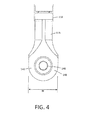
FIG. 4 is a plan view of the distal ablation body portion of the device of FIG. 1.
FIG. 5A is a sectional longitudinal view of the working end of the device of FIG. 1 showing the slotted sleeves configured for articulation.
FIG. 5B is a cut-away view of the working end similar to FIG. 5A showing an electrode arrangement.
FIG. 6 is a cut-away view of the distal ablation body portion of the device of FIG. 1 further showing fluid flow pathways.
FIG. 7 is a schematic illustration of the device of FIG. 1 introduced into a knee joint to treat abnormal cartilage.
FIG. 8A is a longitudinal sectional view of the ablation body portion of the device of FIG. 1 showing fluid flows, plasma formation and the use of a low pressure chamber to provide a selected dimension of plasma propagating from a working surface.
FIG. 8B is another longitudinal sectional view of the ablation body portion as in FIG. 8A with the fluid flow parameters altered to provide an alternative dimension of plasma propagating from the working surface.
FIG. 9A is an illustration of a method of the invention in ablating fibrillation in cartilage tissue.
FIG. 9B is another illustration of the method of FIG. 8A which results in a smooth cartilage surface without thermal damage to the cartilage tissue.
FIG. 10A is an illustration of an alternative embodiment of a working end that is articulatable with an independently rotatable ablation body portion.
FIG. 10B is a schematic view of the working end embodiment of FIG. 10A being positioned in a hip joint to treat abnormal cartilage.
FIG. 11 is a schematic view of a RF generator, controller housing and peristaltic pumps corresponding to certain embodiments of the invention.
FIG. 12A is a sectional view of an alternative working end similar to that of FIGS. 3-6, but configured with first and second polarity electrodes disposed in the interior of the working end, wherein FIG. 12A illustrates fluid flows within the device.
FIG. 12B is a schematic cut-away view of the working end of FIG. 12A showing the RF current paths which can be substantially confined to the interior of the working end.
FIG. 13 is a schematic sectional view of another alternative working end with a different passageway configuration that carries an interior electrode.
FIG. 14A is a sectional view of a ceramic core component of an alternative working end with a different passageway including a valve.
FIG. 14B is a sectional view of another ceramic core component of a working end with a different passageway including exposure to a passive conductive or capacitive material.
FIG. 15A is a sectional view of a working end variation configured with first and second polarity electrodes disposed in the interior of the working end, wherein one electrode is within an aspiration channel, with FIG. 15A illustrating fluid flows within the device.
FIG. 15B is a schematic cut-away view of the working end of FIG. 15A showing the RF current paths which can be substantially confined to the interior of the working end.
FIG. 16A is a perspective view of an alternative working end configured with first and second polarity electrodes disposed in interior channels and a tissue extraction lumen.
FIG. 16B is a perspective view of the working end of FIG. 16A de-mated from it shaft showing the flow channels in the working end.
FIG. 17A is a sectional view of the working end of FIGS. 16A-16B showing a looped inflow-outflow channels and a first polarity electrode disposed in an interior channel, and illustrating fluid flows within the working end.
FIG. 17B is another sectional view of the working end of FIGS. 16A-16B showing a tissue extraction channel and a second polarity electrode disposed in this channel, and further illustrating a fluid flow path through the working end.
FIG. 18A is another sectional view of the working end of FIGS. 16A-16B showing fluid flows within and through the working end and first and second polarity electrodes disposed in the interior of the working end.
FIG. 18B is a sectional view as in FIG. 18A showing the RF current paths between the first and second polarity electrodes which are substantially confined to the interior of the working end.
FIG. 19 is a cut-away view of an alternative working end similar to that of FIGS. 16A-18B configured with an additional inflow channel for delivering a saline distension fluid to a working space and an alternative electrode arrangement.
FIG. 20 is a sectional view of another working end variation similar to that of FIGS. 16A-18B with a different annular interface between dielectric bodies configured for plasma formation therein and plasma propagation therethrough together with an alternative electrode arrangement.
DETAILED DESCRIPTION OF THE INVENTION
Referring now to the drawings and the reference numbers marked thereon, FIGS. 1 and 2 illustrate one embodiment of chondroplasty plasma ablation device 100 that includes handle portion 104 and elongated shaft 105 that extends along longitudinal axis 108. The working end 110 comprises an articulating shaft portion 112 that allows the distal ablation body portion 115 to be articulated to 90° or more to thus allow the physician to orient the distal ablation body portion 115 as needed in a joint to ablate and smooth damaged regions of an articular surface, such as in a knee, hip, shoulder, ankle or other joint. In one embodiment, the shaft 105 comprises an assembly of concentric thin-wall inner and outer stainless steel sleeves 120 a and 120 b with an outermost assembly diameter of approximately 3.0 mm (FIGS. 2-3). An insulative polymer outer layer 118 is provided around the shaft 105, which can comprise a flexible temperature resistant material such as PEEK. It should be appreciated that the shaft 105 can be fabricated of a metal, polymer or combination thereof with a diameter ranging from about 1.0 mm to 6.0 mm. Referring to FIGS. 1, 3, 4 and 5A-5B, the articulating shaft portion 112 comprises inner and outer slotted sleeve portions, 122 a and 122 b, that are coupled at distal weld 124 to thus allow axial forces to be applied to one sleeve relative to the other sleeve to thus articulate the working end 110 as is known in the art. In the embodiment of FIGS. 1 and 2, the inner and outer slotted sleeve portions, 122 a and 122 b, can have any configuration of slot depth, orientation and shape to provide a desired range of articulated shapes, torque resistance and the like.
In FIG. 2, it can be seen that handle grip portion 128 a can be moved toward handle portion 128 b (from an ‘open’ position indicated at A toward a ‘closed’ position indicated at B) to articulate the working end 110. More in particular, the movement of handle portion 128 a about pivot 130 causes the upper handle end block 132 to engage and move flanges 133 a, 133 b of the inner sleeve 120 b distally to thus articulate the working end 110 between a linear shape and an articulated shape. FIGS. 1 and 2 illustrate that the shaft 105 is rotatable relative to handle 104 by manipulation of rotation collar 135 that is rotatably coupled to projecting portion 136 of the handle. The moveable handle portion 128 a is further configured with a ratchet-detent member 137 a that engages detents 137 b in handle portion 128 b which is adapted to releasably maintain the handle portions and working end 110 in a selected articulated shape. By moving the moveable handle portion 128 a toward an ‘open’ position A, the working end 110 will return to a linear configuration as shown in FIG. 1. Actuator buttons 138 a and 138 b are provided in the grip portion 128 a for changing the RF power level, but also can be configured for ON-OFF actuation of they system and RF power.
Now turning to FIGS. 3-6, the plasma generating system within the working end 110 is shown. FIGS. 3-4 depict one example of distal plasma ablation body portion 115 in a perspective view and in a plan view. In FIGS. 3 and 4, it can be seen that the distal body portion 115 has an expanded width relative to shaft 105 and in one embodiment can extend to a width W ranging from about 4.0 mm to 8.0 mm. FIG. 3 illustrates that the thickness T of the distal body portion is similar to the diameter of shaft 105, for example about 3.0 mm.
Of particular interest, referring to FIGS. 3-6, the entirety of the distal body portion 115 consists of electrically non-conductive materials which can comprise ceramics or a combination of ceramic and polymeric materials. In one embodiment shown in FIGS. 5A, 5B and 6, the body portion 115 comprises a PEEK housing 140, annular or donut-shaped ceramic element 142 that surrounds a core ceramic member indicated at 144. The ceramic annular element 142 and the ceramic core 144 are press-fit and bonded to bores in housing 140 to provide a very slight annular gap 145 having dimension G between the ceramic element 142 and ceramic core 144. Of particular interest, the fluid flow restriction caused by the gap 145, as will be described below, is designed to focus electrical energy density to generate plasma in gap 145. In one embodiment, the dimension G of gap 145 is 0.02 mm, and can range from about 0.005 mm to 0.06 mm. In FIG. 6, it can be seen the annular gap 145 transitions to slightly larger annular channel 146 having width dimension G′ of about 0.08 mm to 0.10 mm which opens to the substantially planar surface 148 of body portion 115.
As will be described in detail below, the plasma ablation region 150 is adjacent and radially inward of the annular channel 146 in the planar surface 148. The finely controlled plasma can be generated to have different geometries dependent upon the operating parameters of power, fluid inflows and fluid outflows.
As described above, since the entire distal body portion 115 comprises electrically non-conductive materials, the working end 110 in FIGS. 5A-6 has its opposing polarity conductive electrodes 155A and 155B positioned remote from a plasma ablation region 150 that extends outward from gap 145 and annular channel 146 of distal body portion 115. As depicted in FIGS. 3 and 5A, the plasma ablation region 150 is indicated as a ‘hatched’ circular region in the center of the substantially planar surface 148 of the distal body portion 115.
Referring now to FIGS. 5A-5B, the first polarity electrode 155A comprises the distal portion of an interior tubular sleeve 160 of the shaft assembly. The second polarity electrode indicated at 155B comprises an exposed portion of outer slotted sleeve 120 a wherein a portion of the flexible outer sleeve 118 is removed. The exposed portion of sleeve 120 a that comprises the electrode can have an area ranging from about 1 mm2 to 20 mm2 and can have any shape, such as an axial, circumferential, helical or another shape.
In one embodiment depicted schematically in FIGS. 5A-5B, the first polarity electrode 155A is spaced proximally a distance D from the center or centerline 156 of the plasma ablation region 150 by at least 20 mm, 30 mm, 40 mm or 50 mm. Similarly, the distal edge 158 of second polarity electrode 155B can be spaced proximally a distance D′ from the centerline 156 of plasma ablation region 152 by at least 10 mm, 20 mm, 30 mm, 40 mm or 50 mm (FIG. 5A).
Referring to FIGS. 5A-5B and 6, the electrical components and the means of operation of system can be understood. In FIG. 5A, it can be seen that a pressurized fluid source 170 is in fluid communication with lumen 172 in conductive central tubular sleeve 160 which transitions into a non-conductive sleeve 175, which can be a polymeric material or a ceramic. In one embodiment, the non-conductive sleeve 175 is a flexible, non-kinkable PEEK that can flex and bend as the working end is articulated. The distal end 158 of conductive sleeve 160 is coupled to the proximal end 176 of non-conductive sleeve 175 by any suitable means such as adhesives (FIG. 6). It be seen in FIGS. 5A-5B and FIG. 6 that lumen 172′ in sleeve 175 has an open termination 176 in chamber 177 in the housing 140.
FIGS. 5A and 6 illustrate another electrically insulative component of the working end 110 that comprises flexible sleeve 180 that in one embodiment comprises a thin-wall FEP. As can be understood, FIGS. 5A and 6, the insulative FEP sleeve is adapted to provide an insulative fluid-tight layer between the first polarity electrode 150A and the slotted tubes 120 a and 120 b that are in the current carrying path to the exposed second polarity electrode 155B. In FIG. 6, it can be seen that the distal end 182 of the insulative sleeve 180 is bonded to sealably bonded the interior bore 184 in the housing 140.
In another aspect of the invention, still referring to FIGS. 5A-6, a circulating flow path is provided through the interior of the device (see arrows in FIG. 6) wherein positive pressure fluid source 170 supplies a saline solution that flows though lumens 172 and 172′ to flow into chamber 177 of the housing 140. Thereafter, the fluid inflow reversed course and flows in the proximal direction in annular passageway 185 within the distal body portion 115 is coupled to negative pressure source 190 and a collection reservoir 192. A controller 195 is provided to control the positive and negative pressures applied within the system to provide a selected rate of liquid flow from the fluid source 170 through the device. The system further includes RF source 200 coupled by electrical leads to the first and second polarity electrodes 155A and 155B.
FIG. 7 is a schematic illustration of a method of use of the plasma ablation device of FIGS. 1-6 in treating cartilage, which is shown in a knee joint 202. Its should be appreciated that the device can be used to treat cartilage in any joint, such as knees, hips, shoulders, ankles and elbows.
FIGS. 8A-8B are cut-away schematic views of the ablation body portion 115 of working end 110 and further illustrate the dimensions of ‘projection’ of the plasma ablation region 150 relative to planar surface 148 of distal body portion 115 when operated under different parameters. In one embodiment shown in FIG. 8A, an inflow of fluid through lumen 172′ from source 170 is provided at a flow rate 10 ml/minute. The outflow of fluid through annular lumen 185 provided by negative pressure source 195 is provided at a flow rate greater than the inflow rate, and in this example is greater than 13 ml/minute. Thus, if the working end is immersed in fluid, such as in an arthroscopic procedure, and the pressurized fluid source 170 and the negative pressure source 195 are actuated without activating the RF source 200, the device will suction fluid from the arthroscopic working space into the interior chamber 177 of the device through annular gap 146—and then outwardly through lumen 185 into the collection reservoir 192. In other words, the inflows and outflows will not be in equilibrium when the RF is not actuated, resulting in suctioning of fluid from the working space. Thus, one aspect of the invention is to provide a system controller 195 that operates the inflow and outflow subsystems to thereby create a substantially low pressure in chamber 177 before the actuation of RF wherein the low pressure allows for generation of a plasma ablation region 150 with unique characteristics.
FIG. 8A depicts the ablation body portion 115 operating under first operating parameters which results in plasma ablation region 150 extending a distance P from the planar surface 148. In FIG. 8A, the operating parameters include creating very low pressures in chamber 177, for example with outflow pressure exceeding inflow pressure by greater than 10%. In operation, when the plasma is generated or ignited by actuation of RF source 200, an equilibrium is created between the inflowing media through lumen 172, the outflowing media through lumen 185, and the plasma projection through annular gap 146. Such an equilibrium is created after the plasma is generated, which initially greatly increases pressure in chamber 177. Thus, the objective of the negative pressure source 195 is demonstrated in FIG. 8A, as the applied suction from negative pressure source 195 causes the plasma to form in a low (below ambient) pressure chamber with suction forces applied to ionized gas (plasma) and flow media that is in a liquid or vapor state. Thus, it can be understood that such negative pressures applied to chamber 177 functions (i) to control the dimension P of the plasma projected from surface 148 and (ii) to cool the plasma projected from surface 148. FIG. 8B illustrates the plasma region 150 being projected from surface 148 a certain dimension P′ which is provided by reducing the net negative pressure applied to interior chamber 177 by inflow and outflow subsystems. In FIG. 8B, the operating parameters include creating a low pressure in chamber 177 wherein outflow pressure exceeds inflow pressure up to 50%.
In general, the method of the invention includes generating an equilibrium plasma in flow media within an interior of a medical device and controlling plasma projection outward of a working end surface a selected dimension ranging from 0.1 mm to 10 mm, or 0.5 mm to 5 mm.
In general, the invention is based on an appreciation of the fact that an RF-generated plasma can be controllably contained in an interior chamber 177 by providing less than ambient pressures in the interior chamber wherein the treatment plasma can be controllable emitted from at least one aperture that is in communication with the interior chamber.
Another aspect of the invention relating to tissue treatment is based on the observation that a plasma can be generated by RF energy in an interior chamber which interfaces with a negative pressure source that has the effect of cooling the plasma. In one embodiment, the temperature (i.e., average mass temperature) of the plasma is less than 80° C., less than 70° C., less than 60° C., or less than 50° C.
Another aspect of the invention is based on an appreciation of the fact that the above-described device can ablate, smooth and volumetrically remove tissue from cartilage surface without causing any thermal damage to non-targeted tissue. The energetic plasma can be generated by RF energy in an interior chamber and then projected from the device surface to ablate tissue, and the lack of collateral damage results in part from the fact that the plasma is cooled by the low pressure chamber, with the plasma temperature being selected to be less than 80° C., less than 70° C., less than 60° C. or less than 50° C.
FIGS. 9A-9B illustrate a method of the invention in treating damaged region 205 of articular cartilage, such as in a patient's knee as shown in FIG. 7. In FIG. 9A, a sectional view of a small a portion of a patients joint shows the cortical or subcondral bone 212, and cartilage layer which consists of radial zone 214, transitional zone 216, and tangential zone 220. The zones 214, 216 and 220 each are characterized by differing collagen fiber orientations with the surface zone having collagen fibers and fibril oriented mostly parallel to the cartilage surface. A common form of chondromalacia or damaged cartilage is shown in FIG. 9A which consists of a fibrillated cartilage surface, wherein collagen fibril bundles 222 of the tangential zone 220 are disrupted and fibril ends 224 float outward from the cartilage surface. Such articular cartilage damage is typically only identified after an MRI scan or when the physician view the joint with an arthroscope. The grading of cartilage damage uses the following nomenclature: Grade 0, the cartilage is normal and intact; Grade 1 cartilage has some softening and blistering; Grade 2 has partial thickness (less than 50%) defects or minor tears in the cartilage surface; Grade 3 has deeper defects (more than 50%) and Grade 4 has full thickness cartilage loss with exposure of the subchondral bone 212.
The device of the present invention is adapted for smoothing a fibrillated cartilage surface as depicted in FIGS. 9A and 9B. FIG. 9A schematically illustrates the ablation body portion 115 introduced into saline 126 that fills the joint space. FIG. 9A further depicts the plasma ablation region 150, which can have a temperature of less than 50° C., extending outward from the device to ablate and remove the fibril ends 224 that are floating into the joint space. FIG. 9B illustrates that cartilage surface after ablation and removal of the fibril ends 224 resulting in a smooth cartilage surface. Tests have been performed with the device of FIGS. 5A-9B on human cartilage tissue immediately after such tissue was removed from a patient in a ‘total knee’ replacement operation. It was found that the treated cartilage surface was very smooth when compared to prior art bi-polar electrode devices with exposed electrodes. In another important aspect of the invention, tests have shown that the plasma region 150 as depicted in FIGS. 9A-9B produce no thermal effects or cell death in the cartilage surface. Tests were performed using confocal laser microscopy as described in Edwards, R, “Thermal Chondroplasty of Chondromalacic Human Cartilage An Ex Vivo Comparison of Bipolar and Monopolar Radiofrequency Devices,” The American Journal of Sports Medicine (2002) Vol. 30, No. 1, p 90. In tests of the present invention, no significant chondrocyte death was found as determined by cell viability staining in conjunction with confocal laser microscopy methods. In contrast, in the Edwards article above, all prior art RF devices that were tested caused substantial cell death in cartilage tissue.
FIG. 10A illustrates another embodiment of working end 110′ wherein the ablation body portion 115 is rotatable relative to shaft 105 no matter how the shaft is articulated. This is accomplished by providing an additional rotatable, torque-able sleeve 230 that carries the ablation body portion 115 and is rotatable within outer articulating sleeve assembly 232. FIG. 11 is a schematic illustration of the working end of FIG. 10A being used in a hip joint 240, wherein the device is introduced through an access cannula 245. After being deployed in the joint space with the introducer shaft 105 being articulated, the ablation end 115 can be rotated (see arrow) to orient the plasma to treat targeted cartilage tissue.
FIG. 11 illustrates a controller box or housing 300 that combines an RF generator source 310, computer controller 315 and positive and negative pressure subsystems configured for operating the ablation devices described above and below. The RF source 310 can be a conventional generator as is known in the art operates at within the range of 100 kHz to 550 kHz, and in one embodiment operates at 150 kHz. The front panel of controller housing 300 carries the exposed roller pump portions of first and second peristaltic pumps 316 and 318 as are known in the art that can be configured as the positive and negative pressure subsystems. The controller and ablation system can be operated from the touch screen display 320. FIG. 11 further shows single-channel or multi-channel tubes 322 and 324 that are detachably coupled to each peristaltic pump 316 and 318 to deliver positive pressure and negative pressure to the ablation device (see FIG. 1). The system further includes a fluid or saline source 330 connected to a positive pressure source to provide fluid inflows to the ablation device and a collection reservoir 335 associated with at least one negative pressure source to collect aspirated fluid and ablation by products. A footswitch 340 is provided for ON-OFF operation of the system and the RF source, although operating controls also can be provided in the handle of the device.
FIGS. 12A-12B illustrate another variation of a plasma ablation working end 400 that configured for chondroplasty procedures. The working end 400 of FIG. 12A is carried at the distal end of shaft 405 and is based on the same operational principles described above in the embodiment of FIGS. 3-6. The shaft 405 extends about axis 406 and can comprise a thin-wall stainless steel tube 407 with insulative inner and outer coatings or layers 408 and 408′. The variation of FIGS. 12A-12B differs in that both first and second polarity electrodes, 410A and 410B, are disposed in interior passageways or regions of the device remote from articular tissue targeted for treatment. This configuration of the opposing polarity electrodes 410A and 410B provides for increased control over RF current paths in the immersed working space which consists of saline 412. More particularly, the electrode configuration can confine RF current paths substantially to the interior channels of the working end 400 and thus limit RF energy density in articular tissue to prevent active Joule heating of such tissue. In other words, the working end variation of FIGS. 12A-12B insures that targeted tissue can be treated with a low temperature plasma alone, which can best be described as “plasma etching” of such articular tissue. Such plasma etching can smooth the cartilage surface without causing thermal damage to cartilage below the articular surface.
The embodiment of FIGS. 12A-12B has a distal body portion or housing 415 that consists of electrically non-conductive materials such as a ceramic or polymer. In the embodiment shown in FIG. 12A, the housing portion 415 is a ceramic mated with an annular, donut-shaped ceramic element 418 that partly surrounds a core ceramic member 420. The annular element 418 and ceramic core 420 extend transversely through interior chamber 422 and are bonded in bores 424 a and 424 b in housing 415 to provide the small annular gap 425 as described previously in which plasma formation is initiated. The annular gap 425 has a dimension as described above to function as a flow restriction wherein plasma 430 (FIG. 12B) can be controllably ignited as described in the previous embodiment. In FIG. 12A, it can be seen that the annular gap 425 transitions into annular channel 432 which has an open termination indicated at 435 from which plasma is projected outwardly. In this embodiment, the open termination 435 is within a recess or concavity 436 in the surface or perimeter 438 of body portion 415. More in particular, the open termination 435 is spaced inwardly from surface 438 a recessed dimension RD that can range from 0.5 mm to 5.0 mm. In operation, the system parameters can be modulated to cause the plasma to be projected outwardly a selected dimension from the open termination 435 of annular channel 432 into the concavity 436.
Still referring to FIG. 12A, the circulating saline flow paths are provided through the interior of the device (see dotted lines and arrows in FIG. 12A) wherein positive pressure fluid source 440 supplies a saline solution that flows though lumen or first channel 442 in insulative sleeve 444 into chamber 422 of the housing 415. Thereafter, the fluid inflow reverses course in the interior chamber 422 which may also be described as a flow transition zone herein. The fluid then can flow in the proximal direction in the concentric passageway or second channel 445 that extends through the distal body portion 415 and shaft 405 and is coupled to negative pressure source 450 and collection reservoir 335 (see FIG. 11). As can be seen in FIG. 12A, the interior chamber 432 or transition zone also communicates with annular gap 425 and annular channel 432 which also is called a third channel herein. A controller 455 is provided to control the positive and negative pressures applied within the system to provide a selected rate of liquid flow from the fluid source 440 through the device. The system further includes RF source 460 that is operatively connected to the first and second polarity electrodes, 410A and 410B. As can be seen in FIGS. 12A and 12B, the second polarity electrode 410B is positioned in the interior of a passageway 462 that extends transverse to the axis of the shaft 405 with open ends on both sides of the working end. Thus, the passageway 462 has a dimension and configuration that permits saline 412 to flow into the passageway 462 as soon as the working end is immersed and thus electrode 410B will be in contact with the conductive saline 412 in the working space while the electrodes is maintained spaced apart from targeted tissue.
In another aspect of the invention, referring to FIG. 12B, it can be seen that RF current paths CP can extend from first polarity electrode 410A through interior chamber 422 and annular channel 432 to the second polarity electrode 410B in passageway 462 without extending substantially outward from the exterior surface 438 of the working end. This aspect of the invention allows for control of plasma as it projects outward from exits annular channel 432 and can confine plasma with the recess 436 in the surface which in turn can control any potential RF energy density is tissue. The plasma's geometry further can be controlled by modulating the operating parameters of applied RF power, fluid inflows and fluid outflows which control operating pressure in interior chamber 422.
Referring to FIGS. 12A-12B, the looped inflow and outflow subsystems provide operating parameters as described previously wherein very low pressures can be created in interior chamber 422 during plasma generation, for example with outflow pressures exceeding inflow pressures by greater than 10%. In one aspect of the invention, the negative pressure source 450 functions to modify the plasma (initiated in gap 425 and then extended outwardly through channel 432) from a volatile plasma to a non-volatile plasma. The term ‘volatile’ plasma, as used herein, is meant to describe the gaseous plasma media in its dynamic phase-transitioning stage, as saline is phase-transitioned instantly form liquid to water vapor and then to an ionized gas. In such a phase-transitioning or ‘volatile’ plasma, there is substantial popping, bubble formation and bubble collapse. Such a volatile plasma with bubble formation and collapse is undesirable in the volume of saline 412 that fills and comprises the working space (FIGS. 12A-12B). Thus, it can be understood the negative pressures applied to chamber 422 can function to suction the bubbles and liquid media from the volatile plasma in the interior chamber 422 to thereby create a non-volatile, non-bubbling plasma that can be extended through annular channel 232 to interface with targeted tissue. As described above, the negative pressures applied to interior chamber 422 additionally function (i) to control the dimension or geometry of the plasma projected outward from open termination 435 of the annular channel 432 and (ii) to cool the plasma projected from channel 432. In FIGS. 12-12B, the operating parameters include creating a low pressure in chamber 422 wherein outflow pressure from negative pressure source 450 exceeds inflow pressure of saline by at least 10%, 20%, 30%, 40% and 50%.
In general, a method corresponding to invention comprises creating a non-volatile plasma in an immersed conductive fluid workspace and interfacing the non-volatile plasma with targeted tissue. The method comprises ablating a targeted body structure with a non-volatile, non-bubbling plasma in a fluid environment which permits endoscopic viewing in the non-bubbling environment. More in particular, the method includes positioning a probe working end in proximity to a targeted structure of a patient's body, wherein the working end includes an interior space, and creating a volatile plasma in the interior space and extending a non-volatile plasma outwardly from the interior space to interface with the targeted structure. The method includes modifying a plasma from volatile to non-volatile. The method further includes modifying the plasma by applying negative pressure to the volatile plasma to remove bubbles and liquid from the volatile plasma. The method includes igniting the plasma in flow media flowing in a looped flow through the interior space 422 in a device working end (FIGS. 12A-12B).
FIG. 13 is a cut-away view of another embodiment of working end 400′ that is similar to the embodiment depicted in FIGS. 12A-12B, in which like reference numbers indicate like features. The variation in FIG. 13 differs only in the configuration of the transverse passageway in ceramic core 420 that extends transverse to the axis 406 of shaft 405 and that carries electrode 410B. In FIG. 13, it can be seen that the transverse passageway has a non-uniform cross-section with larger diameter portion 472 transitioning to smaller diameter portion 474. This variation is adapted to substantially prevent saline flows through the transverse passageway during a treatment interval which might be induced by saline or plasma flows in annular channel 432. The variation of FIG. 13 also shows the open termination 435 of the annular channel 432 is within a smooth contour concavity 475 in the working end.
FIGS. 14A-14B illustrate alternative ceramic cores 420′ and 420″ that can be used in the working end embodiments of FIG. 12A or FIG. 13. The variations of FIGS. 14A-14B are again adapted to control saline flow in the transverse passageway in the ceramic core while still insuring that a conductive path is provided interior electrode 410B which is exposed to the passageway. In FIG. 14A, it can be seen that the transverse passageway 482 has a flap-valve 485 or any type of one-way valve in transverse passageway portion 486 to limit, but permit, saline flows into and/or through the passageway. FIG. 14B depicts a closed-end passageway 492 that carries electrode 410B. In FIG. 14B, the closed end 494 of the passageway interfaces with a conductive or capacitive material 496 that is not coupled to electrode 410B but can potentially carry current to saline in the passageway 492. It should be appreciated that the open end of the passageways 482 and 492 in FIGS. 14-14B can be oriented in either direction relative to opening 435 of annular channel 432.
FIGS. 15A-15B are cut-away views of another embodiment of working end 500 that is similar to the embodiment depicted in FIGS. 12A-12B and again in which like reference numbers indicate like features. The embodiment of variation in FIGS. 15A-15B includes opposing polarity electrodes 510A and 510B disposed within active fluid flow passageways in the interior of the working end 500. In this embodiment, a second negative pressure source 515 is provided which is configured to suction flow media and fibrillated cartilage into an interface with plasma projecting outward from the opening 435 of annular channel 432. Further, the second negative pressure source 515 can extract ablation debris and bubbles from saline 412 during operation. More in particular, the second negative pressure source 515 is coupled to aspiration lumen or fourth channel 520 in insulative sleeve 522 that extends to opening 524 in transverse passageway 532 within the ceramic cores 420. As can be seen in FIG. 15A, the saline inflow from source 440 is similar to previous embodiments wherein circulating saline inflows and outflows are provided through inflow channel 536 in insulative sleeve 538 and thereafter through interior chamber 422 and outflow channel 540. In this embodiment, the first polarity electrode 510A is carried in inflow channel 536 and the second polarity electrode 510B is carried in aspiration channel 520. FIG. 15A shows the various flow channels as being concentric for convenience, and it should be appreciated that any configuration of the multiple channels can be used.
In operation, FIG. 15A indicates the various fluid flows by dotted lines and arrows. In FIG. 15B, the RF current paths CP are shown during operation in the same manner as shown in FIG. 12B to illustrate the formation of plasma 445 in the flow restriction. As can be seen in FIG. 15B, the RF current path extends from first electrode 510A exposed to saline in flow channel 536 through the flow restriction 425 (see FIG. 15A) and then through transverse passageway 532 and lumen 520 to second electrode 510B. As in the embodiment of FIGS. 12A-12B, the RF current paths are substantially confined to the interior of the working end which lowers or eliminates RF current density in tissue. In all other respects, the working end 500 functions as described previously.
FIGS. 16A-18B illustrate another electrosurgical system 600 and working end 605 that is adapted for chondroplasty procedures. In FIG. 16, it can be seen that a round or oval probe shaft 610 carries a dielectric working end 605 that can comprises ceramic bodies as generally described above. The shaft 610 can comprise a stainless steel tube covered with a thin wall dielectric material 611. In one embodiment, the distal working end 605 comprises an assembly of first and second ceramic bodies 612A and 612B (e.g., zirconium) that define an interface 615 therebetween. Both ceramic bodies 612A and 612B are carried in ceramic housing 614. The interface 615 between the ceramic bodies 612A and 612B (see FIG. 18A), terminating in gap G in the surface 618, can be extremely tight and in one embodiment the interface is sufficiently fluid-tight to prevent liquid flow therethrough but still permit electrons and plasma to propagate through the interface 615. In working end 605 of FIGS. 16A-18B, the first and second polarity electrodes, 620A and 620B are disposed entirely within the interior of ceramic bodies 612A and 612B with no exposure in the working surface 618 or shaft 610.
Now turning to FIG. 16B, the ceramic working end 605 is shown de-mated from the shaft 610. In FIG. 16B, it can be seen that there is a looped or circulating first inflow channel 622A and second outflow channel 622B wherein a positive pressure source 625 delivers saline solution through first channel 622A and around the interior channel portion 630 (see FIG. 17A) adjacent the interface 615 between ceramic bodies 612A and 612B (see FIG. 18A). A negative pressure source 635 is configured to draw or suction the saline through channel 622B to a remote collection reservoir. In addition, the negative pressure source 635 communicates with a tissue extraction lumen 640 in the probe shaft and working end 605 which has an open termination 644 in working surface 622. In one embodiment, a single negative pressure source 635 is used to communicate with both (i) the saline outflow through second channel 622B and (ii) saline outflow through the tissue extraction channel 640. As will be described below, one embodiment provides pressure and/or a flow control mechanism positioned intermediate the negative pressure source 635 and the tissue extraction channel 640. In one such embodiment, the pressure control mechanism comprises a check valve 648 shown schematically in FIG. 16B. Such a check valve or pressure relief valve 648 can be disposed in the working end 605 or in the shaft 610 or in a handle of the device (not shown). The check valve can function to maintain negative pressure parameters in the second channel 622B and channel portion 630 (see FIGS. 17A and 18A) to maintain predetermined plasma ignition parameters in the event the tissue debris clogs the tissue extraction lumen 640.
Now turning to FIG. 17A, a sectional view is provided through a portion of the working end 605 of FIG. 16B and more particularly through the inflow and outflow channels 622A and 622B. It can be seen how the positive pressure source 625 introduces saline through first channel 622A and then around the looped channel portion 630 adjacent the interface 615 between the ceramic bodies 612A and 612B to finally flow into the outflow channel 622 b assisted by the negative pressure source 635. The plasma can be controlled to project through the interface 615 to the working surface 618. FIG. 17A a further shows a first polarity electrode 650A disposed in the inflow channel 622A from which RF current can flow through the interface 615 as will be described below. The electrode 650A is operatively coupled to RF source 655 and controller 660.
FIG. 17B is another section through working end 605 and more particularly through the tissue extraction channel 640 in the working end of FIG. 16B. It can be seen that the single negative pressure source 635 is in fluid communication with the proximal end of the tissue extraction lumen 640 as well as the second channel 622B described above. Further, a second polarity electrode 650B is disposed within the tissue extraction channel 640 so that both polarity electrodes are entirely internal to the working end 605.
FIGS. 18A-18 b are cut-away views of working end 605 that show fluid flows and RF current paths within the working end in using the probe to treat damaged cartilage or similar tissue. Referring to FIG. 18A, the working end 605 is shown disposed in a distending fluid, such as a saline solution, in a working space 662. The dotted lines in FIG. 18A indicate potential and actual fluid flows within the working end and through the working end 604 from the working space. FIG. 18A shows that the negative pressure source 635 is coupled to both the tissue extraction lumen 640 and the outflow lumen 622B. The purpose of the pressure control mechanism or pressure relief valve 648 can be better understood from FIG. 18A. The probe and working end 605 are designed to smooth cartilage in a working space 662 and in some instances the plasma may ablate and extract fibrillations that will clog the tissue extraction lumen 640. In such an instance, there will be an imbalance in the negative pressure source 635 applying suction pressures to both channels 622B and 640. Thus, one embodiment uses as pressure relief valve 648 which can prevent excessive negative pressure from being directed to the second channel 622B when the extraction channel 640 is clogged in which case the excessive negative pressure would alter or diminish plasma formation. In another embodiment, at least one optional pressure sensor 670 (FIG. 18B) can be provided to sense pressure in either or both channels 622B and 640 wherein the sensor can be configured to signal the controller to modulate a valve (not shown) to maintain a predetermined pressure in the second channel 622B to thereby maintain plasma formation in the interface 615. In another embodiment, referring to FIG. 19, the probe can have first and second independently controlled negative pressure sources 635 and 635′ coupled to respective outflow channel 622B and tissue extraction channel 640. In another embodiment, the tissue extraction channel can carry a pressure sensor 670 as described previously (see FIG. 18B) wherein the sensor can sense tissue clogging the channel in which case the controller 660 would modulate pressure in the channel between greater negatives pressures, pulsed negative pressures, positive inflow pressures, pulsed inflow pressures, or a combination of such pressure modulations designed to remove the tissue debris clogging the channel 640.
FIG. 18B illustrates the current paths CP within and about the working end 605 during operation in which plasma is generated and translated across a tissue surface. As can be seen in FIG. 18B, both the sleeve like electrodes 650A and 650B are disposed in channels 622A and 640, respectively, in the working end 605 and the RF current paths CP communicates though channel 622A, interface 615 and extraction channel 640 to provide for plasma-tissue contact while both electrodes 650A and 650B are disposed in the interior of the working end 605. Thus, the working end 605 and system creates RF current paths CP that are confined within the working end and extend only slightly into or around a portion of the working surface 618 of the probe. In one aspect of the invention, the fact that both electrodes 650A and 650B are completely internal within the working end means the no high energy densities are created about an electrode adjacent to or in contact with tissue. This in turn means that tissue cannot be heated to high temperatures or carbonized which is undesirable and can lead to elevated immune responses and delay healing of treated tissue.
FIG. 19 illustrates another system and working end embodiment 680 which is similar to that of FIGS. 16A-16B except that this embodiment includes a further inflow channel 682 for delivering a saline distention fluid through probe and outwardly from the working end. In this embodiment, another internal saline flow is provided in the paths as previously described circulating through inflow channel 622A, loop channel portion 630 and outflow channel 622B. The tissue extraction channel 640 is again as described previously. The variation in FIG. 19 has first and second negative pressure sources 635 and 635′ independently coupled to channel 622B and 640. The distension fluid channels 682 in FIG. 19 is operatively coupled to a second positive pressure source 625′ which provides the saline distention fluid. In the working end 680 of FIG. 19, the opposing polarity electrodes 650A and 685 are disposed entirely within the interior of the device. In one embodiment, the first polarity electrode 650A again is carried in inflow channel 622A and the second polarity electrode 685 is carried in the distension fluid inflow channel 682. In operation, it can be understood that current paths CP (not shown) will extend from first polarity internal electrode 650A through interface 615 and inflow channel 682 to the second polarity internal electrode 685.
FIG. 20 illustrates another working end 700 embodiment that is similar to that of FIGS. 16A-18B except that the opposing polarity first and second electrodes 705A and 705B have a different configuration—still positioned within the interior channels of the working end 700. As can be seen in FIG. 20, the inflow and outflow channels 622A and 622B are similar to previous embodiments. The working end 700 further has a fluid extraction channel 640 as described previously. In one variation, the working end 700 has a looped wire first polarity electrode 705A extending through the working end through first inflow channel 622B, around looped channel portion 630 adjacent interface 615 and extending partly through second outflow channel 622B. In the working end 700 of FIG. 20, both the first and second electrodes 705A and 705B are round wires with large surface areas which enhances RF current flow in the fluid environment. This electrode configuration provides an increased surface area to the electrode and extends such an electrode surface around the region of plasma ignition which together with the absence of sharp edges can enhance the uniformity of the plasma generation in the interface 615. The electrode 705A can have any suitable diameter ranging from about 0.005″ to 0.10″. Similarly, the second polarity electrode 705B is configured to have a substantial exposed surface with a length, for example, ranging from 2 mm to 20 mm (and diameter of about 0.005″ to 0.10″) in the tissue-extraction channel 640. The distal end 708 of the electrode 705A is embedded and sealed into ceramic housing 614 to prevent any sharp electrode edges exposed to the channel 640.
As can be understood from FIG. 20, the RF current paths CP between the first and second polarity electrodes 705A and 705B extends through the interface 615 between the ceramic bodies 612A and 612Bt as described previously. In another aspect of the invention, still referring to FIG. 20, the interface 615 has a greatly increased surface area compared to previous embodiments. It can be seen in FIG. 20 that a tapered annual interface 615 is provided between the dielectric bodies 612A and 612B which after assembly comprises an extremely small gap. In one embodiment, the interface is dimensioned to be sufficiently fluid-tight to prevent liquid flow therethrough and will only permit current flows and plasma propagation therethrough. In this embodiment, the tapered interface or taper lock between the first and second dielectric bodies 612A and 612B is provided by a predetermined surface roughness that is fabricated on either or both dielectric bodies 612A and 612B at either side of the interface 615. In other words, the first and second dielectric bodies 612A and 612B are wedged together tightly with a micron or sub-micron dimensioned gap between the surface finishes of the mating dielectric bodies.
In one embodiment, the interface 615 is annular as shown in FIG. 20 and extends between a first interior periphery 710 of the interface 615 and a second exterior periphery 715 of the interface wherein the mean dimension between the inner and outer peripheries ranges from 0.005″ to 0.25″. Although the variation of FIG. 20 illustrates an annular interface 615, the scope of the invention includes any interface configuration such as a linear configuration, an oval configuration, any elongated configuration, or a polygonal or star-shaped configuration. The total area of such an interface 615 can be from 0.01 mm2 to 10 mm2.
In general, a method of ablating tissue corresponding to the invention comprises providing an electrosurgical working end with an interior chamber communicating with a working surface through a space that is sufficiently fluid-tight to prevent liquid flow therethrough but permit plasma propagation therethrough, igniting a plasma in the gap utilizing first and second opposing polarity electrodes positioned on either side of the gap, and controlling propagation of the plasma through the gap to interface with tissue. In one aspect of the invention, the plasma propagation is controlled by controlling pressure interior of the gap. In another aspect of the invention, the plasma propagation is controlled by controlling the dimensions of said gap which can comprised the width or cross section of the gap and/or the dimension between the inner and outer peripheries of the gap.
Although particular embodiments of the present invention have been described above in detail, it will be understood that this description is merely for purposes of illustration and the above description of the invention is not exhaustive. Specific features of the invention are shown in some drawings and not in others, and this is for convenience only and any feature may be combined with another in accordance with the invention. A number of variations and alternatives will be apparent to one having ordinary skills in the art. Such alternatives and variations are intended to be included within the scope of the claims. Particular features that are presented in dependent claims can be combined and fall within the scope of the invention. The invention also encompasses embodiments as if dependent claims were alternatively written in a multiple dependent claim format with reference to other independent claims.

Claims (21)

1. A method for treating a target tissue, said method comprising:
providing a probe having an interior space comprising a gap in a working end with a working surface, wherein the gap has an interior periphery and an exterior periphery with a spacing therebetween;
igniting a conductive media in the gap to produce a plasma within the gap, wherein the plasma propagates outwardly from the working surface; and
exposing the target tissue to the plasma, wherein the gap is sufficiently fluid tight to inhibit liquid flow but permit plasma propagation therethrough.
2. A method as in claim 1, wherein the plasma is ignited by applying electrical energy to the conductive media from opposite polarity electrodes.
3. A method as in claim 2, wherein a first polarity electrode is disposed in proximity to the inner periphery.
4. A method as in claim 3, wherein the first polarity electrode is in a fluid channel in communication with said inner periphery.
5. A method as in claim 4, further comprising a second polarity electrode in the working end in potential fluid communication with said exterior periphery.
6. A method as in claim 1, wherein a mean dimension between said interior and exterior peripheries of the gap is from 0.005 inch to 0.25 inch.
7. A method as in claim 1, wherein the total area of the gap is from 0.01 mm2 to 10 mm2.
8. A method as in claim 1, wherein the gap has an annular configuration, a linear configuration, an oval configuration, an elongated configuration, or a star-shaped configuration.
9. A method as in claim 1, wherein a propagation rate of the plasma is controlled by varying a pressure of the conductive media in the interior space.
10. A method as in claim 9, wherein the conductive media is introduced into the interior space under a controlled pressure.
11. A method as in claim 9, wherein the conductive media is removed from the interior space under a controlled negative pressure.
12. A method as in claim 1, wherein igniting the conductive media comprises establishing a continuous loop flow of a conductive media through the interior space wherein a portion of the conductive media is ignited within the interior space and a remainder exits the interior space.
13. A method as in claim 1, wherein a propagation rate of the plasma is controlled by varying an inlet pressure of conductive media in an inlet channel and an outlet pressure of conductive media in the gap.
14. A method as in claim 1, wherein the plasma propagates from the working surface by a distance less than 2 mm.
15. A method as in claim 1, wherein the plasma has a temperature less than 80° C.
16. A method as in claim 1, wherein the tissue comprises cartilage.
17. A method as in claim 1, wherein the conductive media comprises saline.
18. A method as in claim 1, wherein the target tissue is submerged in the conductive media.
19. A method for treating a target tissue, said method comprising:
providing a probe having space comprising a gap in a working end with a working surface;
igniting a conductive media in the gap to produce a plasma within the gap, wherein the plasma propagates outwardly from the working surface;
exposing the target tissue to the plasma; and
controlling a rate of propagation through the gap, wherein the plasma propagation rate is controlled by controlling a dimension of said gap.
20. A method as in claim 19, wherein the plasma propagation rate is controlled by controlling a width of said gap.
21. A method as in claim 20, wherein the plasma propagation rate is controlled by controlling the dimension of said gap between a plasma ignition region and the working surface.
US13/287,315 2011-03-21 2011-11-02 Medical ablation system and method of use Active US8323280B2 (en)

Priority Applications (6)

Application Number Priority Date Filing Date Title
US13/287,315 US8323280B2 (en) 2011-03-21 2011-11-02 Medical ablation system and method of use
US13/664,232 US9277954B2 (en) 2011-03-21 2012-10-30 Medical ablation system and method of use
US14/982,593 US9827037B2 (en) 2011-04-11 2015-12-29 Tissue extraction devices and methods
US15/045,055 US10292751B2 (en) 2011-03-21 2016-02-16 Medical ablation system and method of use
US16/385,256 US20200107871A1 (en) 2011-03-21 2019-04-16 Medical ablation system and method of use
US17/158,612 US11712282B2 (en) 2011-03-21 2021-01-26 Medical ablation system and method of use

Applications Claiming Priority (4)

Application Number Priority Date Filing Date Title
US201161454901P 2011-03-21 2011-03-21
US201161491541P 2011-05-31 2011-05-31
US201161537483P 2011-09-21 2011-09-21
US13/287,315 US8323280B2 (en) 2011-03-21 2011-11-02 Medical ablation system and method of use

Related Child Applications (1)

Application Number Title Priority Date Filing Date
US13/664,232 Continuation US9277954B2 (en) 2011-03-21 2012-10-30 Medical ablation system and method of use

Publications (2)

Publication Number Publication Date
US20120245580A1 US20120245580A1 (en) 2012-09-27
US8323280B2 true US8323280B2 (en) 2012-12-04

Family

ID=46877959

Family Applications (5)

Application Number Title Priority Date Filing Date
US13/287,315 Active US8323280B2 (en) 2011-03-21 2011-11-02 Medical ablation system and method of use
US13/664,232 Active 2033-02-17 US9277954B2 (en) 2011-03-21 2012-10-30 Medical ablation system and method of use
US15/045,055 Active 2032-12-19 US10292751B2 (en) 2011-03-21 2016-02-16 Medical ablation system and method of use
US16/385,256 Abandoned US20200107871A1 (en) 2011-03-21 2019-04-16 Medical ablation system and method of use
US17/158,612 Active 2032-09-02 US11712282B2 (en) 2011-03-21 2021-01-26 Medical ablation system and method of use

Family Applications After (4)

Application Number Title Priority Date Filing Date
US13/664,232 Active 2033-02-17 US9277954B2 (en) 2011-03-21 2012-10-30 Medical ablation system and method of use
US15/045,055 Active 2032-12-19 US10292751B2 (en) 2011-03-21 2016-02-16 Medical ablation system and method of use
US16/385,256 Abandoned US20200107871A1 (en) 2011-03-21 2019-04-16 Medical ablation system and method of use
US17/158,612 Active 2032-09-02 US11712282B2 (en) 2011-03-21 2021-01-26 Medical ablation system and method of use

Country Status (1)

Country Link
US (5) US8323280B2 (en)

Cited By (29)

* Cited by examiner, † Cited by third party
Publication number Priority date Publication date Assignee Title
US20110306970A1 (en) * 2010-06-14 2011-12-15 Mehdi Razavi Sheath And Method Of Use
US20120232545A1 (en) * 2011-03-11 2012-09-13 Minerva Surgical, Inc. System and method for endometrial ablation
US9204918B2 (en) 2011-09-28 2015-12-08 RELIGN Corporation Medical ablation system and method of use
US9247983B2 (en) 2011-11-14 2016-02-02 Arqos Surgical, Inc. Medical instrument and method of use
US9277954B2 (en) 2011-03-21 2016-03-08 Arqos Surgical, Inc. Medical ablation system and method of use
US9585675B1 (en) 2015-10-23 2017-03-07 RELIGN Corporation Arthroscopic devices and methods
US9603656B1 (en) 2015-10-23 2017-03-28 RELIGN Corporation Arthroscopic devices and methods
US9681913B2 (en) 2015-04-21 2017-06-20 RELIGN Corporation Arthroscopic devices and methods
US10004556B2 (en) 2013-05-10 2018-06-26 Corinth MedTech, Inc. Tissue resecting devices and methods
US10022140B2 (en) 2016-02-04 2018-07-17 RELIGN Corporation Arthroscopic devices and methods
US10213246B2 (en) 2009-11-13 2019-02-26 Hermes Innovations Llc Tissue ablation systems and method
WO2019213090A1 (en) 2018-04-30 2019-11-07 Aaron Germain Arthroscopic devices and methods
US10595889B2 (en) 2016-04-11 2020-03-24 RELIGN Corporation Arthroscopic devices and methods
US10675087B2 (en) 2015-04-29 2020-06-09 Cirrus Technologies Ltd Medical ablation device and method of use
US11058480B2 (en) 2018-04-27 2021-07-13 RELIGN Corporation Arthroscopic devices and methods
US11065023B2 (en) 2017-03-17 2021-07-20 RELIGN Corporation Arthroscopic devices and methods
US11172953B2 (en) 2016-04-11 2021-11-16 RELIGN Corporation Arthroscopic devices and methods
US11207119B2 (en) 2016-03-11 2021-12-28 RELIGN Corporation Arthroscopic devices and methods
US11253311B2 (en) 2016-04-22 2022-02-22 RELIGN Corporation Arthroscopic devices and methods
US11259787B2 (en) 2013-10-15 2022-03-01 Hermes Innovations Llc Laparoscopic device
US11426231B2 (en) 2017-01-11 2022-08-30 RELIGN Corporation Arthroscopic devices and methods
US11554214B2 (en) 2019-06-26 2023-01-17 Meditrina, Inc. Fluid management system
US11576718B2 (en) 2016-01-20 2023-02-14 RELIGN Corporation Arthroscopic devices and methods
US11672593B2 (en) 2018-04-23 2023-06-13 RELIGN Corporation Arthroscopic devices and methods
US11723681B2 (en) 2017-12-27 2023-08-15 RELIGN Corporation Arthroscopic devices and methods
US11766291B2 (en) 2016-07-01 2023-09-26 RELIGN Corporation Arthroscopic devices and methods
US11883053B2 (en) 2018-04-23 2024-01-30 RELIGN Corporation Arthroscopic devices and methods
US11896282B2 (en) 2009-11-13 2024-02-13 Hermes Innovations Llc Tissue ablation systems and method
US11911086B2 (en) 2008-10-21 2024-02-27 Hermes Innovations Llc Endometrial ablation devices and systems

Families Citing this family (7)

* Cited by examiner, † Cited by third party
Publication number Priority date Publication date Assignee Title
WO2014042665A1 (en) * 2012-09-11 2014-03-20 American Eagle Instruments, Inc. Electrical discharge irrigator apparatus and method
US10898705B2 (en) 2012-09-11 2021-01-26 G&H Technologies, Llc Electrical discharge irrigator apparatus and method
EP3222121B1 (en) 2014-11-19 2021-08-18 Technion Research & Development Foundation Ltd. Cold plasma generating system
GB2559585A (en) * 2017-02-09 2018-08-15 Helica Instrument Ltd Probe for a plasma flame generating apparatus
US11207092B2 (en) 2017-03-27 2021-12-28 RELIGN Corporation Arthroscopic devices and methods
US20220071684A1 (en) * 2018-12-19 2022-03-10 Apyx Medical Corporation Devices, systems and methods for subdermal coagulation
US11490948B2 (en) * 2019-11-06 2022-11-08 Insightful Instruments, Inc. Systems for incising tissue

Citations (60)

* Cited by examiner, † Cited by third party
Publication number Priority date Publication date Assignee Title
US2513564A (en) 1945-06-16 1950-07-04 Mechanical Products Inc Bimetallic overload circuit breaker
US2514545A (en) 1946-07-11 1950-07-11 Mechanical Products Inc Circuit breaker
US2625625A (en) 1950-06-02 1953-01-13 Mechanical Products Inc Free trip circuit breaker
US2689895A (en) 1953-01-19 1954-09-21 Mechanical Products Inc Electric circuit breaker with spark sealed casing
US3611023A (en) 1970-02-19 1971-10-05 Varian Associates Circuitry for triggering a spark gap
US3838242A (en) * 1972-05-25 1974-09-24 Hogle Kearns Int Surgical instrument employing electrically neutral, d.c. induced cold plasma
US3848211A (en) 1973-12-14 1974-11-12 Robertshaw Controls Co Electrical switch construction and an electrical control system utilizing the same or the like
US3868614A (en) 1971-07-06 1975-02-25 Aiken Ind Inc Improved circuit breaker trip mechanism
US3903891A (en) 1968-01-12 1975-09-09 Hogle Kearns Int Method and apparatus for generating plasma
US4060088A (en) 1976-01-16 1977-11-29 Valleylab, Inc. Electrosurgical method and apparatus for establishing an electrical discharge in an inert gas flow
US4272687A (en) 1979-03-05 1981-06-09 Borkan William N Power manageable circuit breaker
US4781175A (en) * 1986-04-08 1988-11-01 C. R. Bard, Inc. Electrosurgical conductive gas stream technique of achieving improved eschar for coagulation
US4977346A (en) 1988-06-29 1990-12-11 North American Philips Corp. High pressure sodium discharge lamp having gas filled outer envelope
US5012495A (en) 1990-03-19 1991-04-30 Eagle Electric Mfg. Co. Inc. Switch and circuit breaker combination device
US5122138A (en) * 1990-11-28 1992-06-16 Manwaring Kim H Tissue vaporizing accessory and method for an endoscope
US5207675A (en) 1991-07-15 1993-05-04 Jerome Canady Surgical coagulation device
US5256138A (en) 1990-10-04 1993-10-26 The Birtcher Corporation Electrosurgical handpiece incorporating blade and conductive gas functionality
US5669907A (en) 1995-02-10 1997-09-23 Valleylab Inc. Plasma enhanced bipolar electrosurgical system
US5720745A (en) * 1992-11-24 1998-02-24 Erbe Electromedizin Gmbh Electrosurgical unit and method for achieving coagulation of biological tissue
US5776092A (en) 1994-03-23 1998-07-07 Erbe Elektromedizin Gmbh Multifunctional surgical instrument
US5849010A (en) 1994-10-31 1998-12-15 Helmut Wurzer Electrosurgical apparatus and method for its operation
US5964752A (en) * 1998-02-02 1999-10-12 Stone; Kevin R. Articular cartilage surface shaping apparatus and method
US6013076A (en) 1996-01-09 2000-01-11 Gyrus Medical Limited Electrosurgical instrument
US6013075A (en) 1994-12-30 2000-01-11 Technova Incorporated Medical coagulation apparatus
US6039736A (en) 1998-09-29 2000-03-21 Sherwood Services Ag Side-Fire coagulator
US6056747A (en) 1997-08-04 2000-05-02 Gynecare, Inc. Apparatus and method for treatment of body tissues
US6099523A (en) * 1995-06-27 2000-08-08 Jump Technologies Limited Cold plasma coagulator
EP1034747A1 (en) 1999-03-05 2000-09-13 Gyrus Medical Limited Electrosurgery system and instrument
WO2000053112A2 (en) 1999-03-05 2000-09-14 Gyrus Medical Limited Dual frequency electrosurgery system
WO2000062685A1 (en) 1999-04-16 2000-10-26 Arthrocare Corporation Systems and methods for electrosurgical removal of the stratum corneum
US6142992A (en) 1993-05-10 2000-11-07 Arthrocare Corporation Power supply for limiting power in electrosurgery
US6159208A (en) 1995-06-07 2000-12-12 Arthocare Corporation System and methods for electrosurgical treatment of obstructive sleep disorders
US6225883B1 (en) 2000-02-15 2001-05-01 Eaton Corporation Circuit breaker with latch and toggle mechanism operating in perpendicular planes
US6235020B1 (en) 1993-05-10 2001-05-22 Arthrocare Corporation Power supply and methods for fluid delivery in electrosurgery
US6238391B1 (en) * 1995-06-07 2001-05-29 Arthrocare Corporation Systems for tissue resection, ablation and aspiration
US6348051B1 (en) * 1997-07-14 2002-02-19 Erbe Elektromedizin Gmbh Preparation instruments
US6413256B1 (en) 2000-08-01 2002-07-02 Csaba Truckai Voltage threshold ablation method and apparatus
US6419674B1 (en) 1996-11-27 2002-07-16 Cook Vascular Incorporated Radio frequency dilator sheath
US6443948B1 (en) * 1998-06-24 2002-09-03 Nikval International Ab Plasma knife
US6475215B1 (en) * 2000-10-12 2002-11-05 Naim Erturk Tanrisever Quantum energy surgical device and method
US20030014051A1 (en) 2001-06-18 2003-01-16 Arthrocare Corporation Electrosurgical apparatus having compound return electrode
US6538549B1 (en) 2001-08-30 2003-03-25 Blue Sea Systems Advanced electrical circuit breaker system and method
US6579289B2 (en) * 2000-06-19 2003-06-17 Erbe Elektromedizin Gmbh Probe electrode
US6632220B1 (en) 1992-01-07 2003-10-14 Arthrocare Corp. Systems for electrosurgical tissue treatment in conductive fluid
US6669694B2 (en) * 2000-09-05 2003-12-30 John H. Shadduck Medical instruments and techniques for highly-localized thermally-mediated therapies
US6720856B1 (en) 2002-12-18 2004-04-13 Texas Instruments Incorporated Calibration structure for circuit breakers having bimetallic trip member
US6780178B2 (en) 2002-05-03 2004-08-24 The Board Of Trustees Of The Leland Stanford Junior University Method and apparatus for plasma-mediated thermo-electrical ablation
US20050075630A1 (en) 2000-08-01 2005-04-07 Dfine, Inc. Voltage threshold ablation apparatus
US6890332B2 (en) * 1999-05-24 2005-05-10 Csaba Truckai Electrical discharge devices and techniques for medical procedures
US20050228372A1 (en) 2000-08-01 2005-10-13 Sciogen, Inc. Voltage threshold ablation apparatus
US20060224154A1 (en) 2001-12-07 2006-10-05 Shadduck John H Medical instrument and method of use
US20080097425A1 (en) 2005-03-24 2008-04-24 Csaba Truckai Electrosurgical ablation apparatus and method
US20090076498A1 (en) 2007-08-31 2009-03-19 Voyage Medical, Inc. Visualization and ablation system variations
US7549989B2 (en) 2001-08-15 2009-06-23 Nuortho Surgical, Inc. Electrosurgery devices
US20100100091A1 (en) 2008-10-21 2010-04-22 Hermes Innovations Llc Tissue ablation systems
US7713269B2 (en) 2000-08-18 2010-05-11 Nuortho Surgical, Inc. Devices for electrosurgery
US7771422B2 (en) 2002-06-06 2010-08-10 Nuortho Surgical, Inc. Methods and devices for electrosurgery
US7819861B2 (en) 2001-05-26 2010-10-26 Nuortho Surgical, Inc. Methods for electrosurgical electrolysis
US8016823B2 (en) * 2003-01-18 2011-09-13 Tsunami Medtech, Llc Medical instrument and method of use
US8192424B2 (en) 2007-01-05 2012-06-05 Arthrocare Corporation Electrosurgical system with suction control apparatus, system and method

Family Cites Families (27)

* Cited by examiner, † Cited by third party
Publication number Priority date Publication date Assignee Title
US5697909A (en) 1992-01-07 1997-12-16 Arthrocare Corporation Methods and apparatus for surgical cutting
US5449356A (en) 1991-10-18 1995-09-12 Birtcher Medical Systems, Inc. Multifunctional probe for minimally invasive surgery
US5683366A (en) 1992-01-07 1997-11-04 Arthrocare Corporation System and method for electrosurgical tissue canalization
US6024733A (en) 1995-06-07 2000-02-15 Arthrocare Corporation System and method for epidermal tissue ablation
US5281217A (en) 1992-04-13 1994-01-25 Ep Technologies, Inc. Steerable antenna systems for cardiac ablation that minimize tissue damage and blood coagulation due to conductive heating patterns
US5277201A (en) 1992-05-01 1994-01-11 Vesta Medical, Inc. Endometrial ablation apparatus and method
US5766153A (en) 1993-05-10 1998-06-16 Arthrocare Corporation Methods and apparatus for surgical cutting
US6149620A (en) 1995-11-22 2000-11-21 Arthrocare Corporation System and methods for electrosurgical tissue treatment in the presence of electrically conductive fluid
ES2154824T5 (en) 1995-06-23 2005-04-01 Gyrus Medical Limited ELECTROCHIRURGICAL INSTRUMENT.
US5817092A (en) 1995-11-09 1998-10-06 Radio Therapeutics Corporation Apparatus, system and method for delivering radio frequency energy to a treatment site
US6917834B2 (en) 1997-12-03 2005-07-12 Boston Scientific Scimed, Inc. Devices and methods for creating lesions in endocardial and surrounding tissue to isolate focal arrhythmia substrates
US7892229B2 (en) 2003-01-18 2011-02-22 Tsunami Medtech, Llc Medical instruments and techniques for treating pulmonary disorders
US5989248A (en) 1998-04-07 1999-11-23 Tu; Hosheng Medical device and methods for treating tissues
US6080152A (en) 1998-06-05 2000-06-27 Medical Scientific, Inc. Electrosurgical instrument
US6394956B1 (en) 2000-02-29 2002-05-28 Scimed Life Systems, Inc. RF ablation and ultrasound catheter for crossing chronic total occlusions
US7517349B2 (en) 2001-10-22 2009-04-14 Vnus Medical Technologies, Inc. Electrosurgical instrument and method
US20040044341A1 (en) 2002-08-27 2004-03-04 Csaba Truckai Electrosurgical device and method of use
US7087054B2 (en) 2002-10-01 2006-08-08 Surgrx, Inc. Electrosurgical instrument and method of use
US7309849B2 (en) 2003-11-19 2007-12-18 Surgrx, Inc. Polymer compositions exhibiting a PTC property and methods of fabrication
US7955331B2 (en) 2004-03-12 2011-06-07 Ethicon Endo-Surgery, Inc. Electrosurgical instrument and method of use
US7220951B2 (en) 2004-04-19 2007-05-22 Surgrx, Inc. Surgical sealing surfaces and methods of use
US8114071B2 (en) 2006-05-30 2012-02-14 Arthrocare Corporation Hard tissue ablation system
US20090270849A1 (en) 2008-03-17 2009-10-29 Arqos Surgical Inc. Electrosurgical Device and Method
DE102009002278A1 (en) 2009-04-08 2010-10-14 Robert Bosch Gmbh Device for producing e.g. non-thermal plasma, for treatment of e.g. chronic wounds, has plasma and ultrasonic effective areas arranged next to each other, and three electrodes for generating plasma and ultrasonic pulses
EP2670331B1 (en) 2011-02-04 2023-10-04 Arqos Surgical, Inc. Medical ablation system
US8323280B2 (en) 2011-03-21 2012-12-04 Arqos Surgical, Inc. Medical ablation system and method of use
US8512326B2 (en) 2011-06-24 2013-08-20 Arqos Surgical, Inc. Tissue extraction devices and methods

Patent Citations (67)

* Cited by examiner, † Cited by third party
Publication number Priority date Publication date Assignee Title
US2513564A (en) 1945-06-16 1950-07-04 Mechanical Products Inc Bimetallic overload circuit breaker
US2514545A (en) 1946-07-11 1950-07-11 Mechanical Products Inc Circuit breaker
US2625625A (en) 1950-06-02 1953-01-13 Mechanical Products Inc Free trip circuit breaker
US2689895A (en) 1953-01-19 1954-09-21 Mechanical Products Inc Electric circuit breaker with spark sealed casing
US3903891A (en) 1968-01-12 1975-09-09 Hogle Kearns Int Method and apparatus for generating plasma
US3611023A (en) 1970-02-19 1971-10-05 Varian Associates Circuitry for triggering a spark gap
US3868614A (en) 1971-07-06 1975-02-25 Aiken Ind Inc Improved circuit breaker trip mechanism
US3838242A (en) * 1972-05-25 1974-09-24 Hogle Kearns Int Surgical instrument employing electrically neutral, d.c. induced cold plasma
US3848211A (en) 1973-12-14 1974-11-12 Robertshaw Controls Co Electrical switch construction and an electrical control system utilizing the same or the like
US4060088A (en) 1976-01-16 1977-11-29 Valleylab, Inc. Electrosurgical method and apparatus for establishing an electrical discharge in an inert gas flow
US4272687A (en) 1979-03-05 1981-06-09 Borkan William N Power manageable circuit breaker
US4781175A (en) * 1986-04-08 1988-11-01 C. R. Bard, Inc. Electrosurgical conductive gas stream technique of achieving improved eschar for coagulation
US4977346A (en) 1988-06-29 1990-12-11 North American Philips Corp. High pressure sodium discharge lamp having gas filled outer envelope
US5012495A (en) 1990-03-19 1991-04-30 Eagle Electric Mfg. Co. Inc. Switch and circuit breaker combination device
US5256138A (en) 1990-10-04 1993-10-26 The Birtcher Corporation Electrosurgical handpiece incorporating blade and conductive gas functionality
US5122138A (en) * 1990-11-28 1992-06-16 Manwaring Kim H Tissue vaporizing accessory and method for an endoscope
US5207675A (en) 1991-07-15 1993-05-04 Jerome Canady Surgical coagulation device
US6632220B1 (en) 1992-01-07 2003-10-14 Arthrocare Corp. Systems for electrosurgical tissue treatment in conductive fluid
US5720745A (en) * 1992-11-24 1998-02-24 Erbe Electromedizin Gmbh Electrosurgical unit and method for achieving coagulation of biological tissue
US6142992A (en) 1993-05-10 2000-11-07 Arthrocare Corporation Power supply for limiting power in electrosurgery
US6235020B1 (en) 1993-05-10 2001-05-22 Arthrocare Corporation Power supply and methods for fluid delivery in electrosurgery
US5776092A (en) 1994-03-23 1998-07-07 Erbe Elektromedizin Gmbh Multifunctional surgical instrument
US6296636B1 (en) 1994-05-10 2001-10-02 Arthrocare Corporation Power supply and methods for limiting power in electrosurgery
US5849010A (en) 1994-10-31 1998-12-15 Helmut Wurzer Electrosurgical apparatus and method for its operation
US6013075A (en) 1994-12-30 2000-01-11 Technova Incorporated Medical coagulation apparatus
US5669907A (en) 1995-02-10 1997-09-23 Valleylab Inc. Plasma enhanced bipolar electrosurgical system
US6159208A (en) 1995-06-07 2000-12-12 Arthocare Corporation System and methods for electrosurgical treatment of obstructive sleep disorders
US6238391B1 (en) * 1995-06-07 2001-05-29 Arthrocare Corporation Systems for tissue resection, ablation and aspiration
US6099523A (en) * 1995-06-27 2000-08-08 Jump Technologies Limited Cold plasma coagulator
US6013076A (en) 1996-01-09 2000-01-11 Gyrus Medical Limited Electrosurgical instrument
US6419674B1 (en) 1996-11-27 2002-07-16 Cook Vascular Incorporated Radio frequency dilator sheath
US6348051B1 (en) * 1997-07-14 2002-02-19 Erbe Elektromedizin Gmbh Preparation instruments
US6056747A (en) 1997-08-04 2000-05-02 Gynecare, Inc. Apparatus and method for treatment of body tissues
US5964752A (en) * 1998-02-02 1999-10-12 Stone; Kevin R. Articular cartilage surface shaping apparatus and method
US6443948B1 (en) * 1998-06-24 2002-09-03 Nikval International Ab Plasma knife
US6039736A (en) 1998-09-29 2000-03-21 Sherwood Services Ag Side-Fire coagulator
WO2000053112A2 (en) 1999-03-05 2000-09-14 Gyrus Medical Limited Dual frequency electrosurgery system
EP1034747A1 (en) 1999-03-05 2000-09-13 Gyrus Medical Limited Electrosurgery system and instrument
WO2000062685A1 (en) 1999-04-16 2000-10-26 Arthrocare Corporation Systems and methods for electrosurgical removal of the stratum corneum
US6890332B2 (en) * 1999-05-24 2005-05-10 Csaba Truckai Electrical discharge devices and techniques for medical procedures
US6225883B1 (en) 2000-02-15 2001-05-01 Eaton Corporation Circuit breaker with latch and toggle mechanism operating in perpendicular planes
US6579289B2 (en) * 2000-06-19 2003-06-17 Erbe Elektromedizin Gmbh Probe electrode
US7744595B2 (en) 2000-08-01 2010-06-29 Arqos Surgical, Inc. Voltage threshold ablation apparatus
US20100305565A1 (en) 2000-08-01 2010-12-02 Arqos Surgical, Inc. Voltage threshold ablation apparatus
US20040010249A1 (en) 2000-08-01 2004-01-15 Csaba Truckai Voltage threshold ablation apparatus
US6821275B2 (en) 2000-08-01 2004-11-23 Csaba Truckai Voltage threshold ablation apparatus
US20050075630A1 (en) 2000-08-01 2005-04-07 Dfine, Inc. Voltage threshold ablation apparatus
US6413256B1 (en) 2000-08-01 2002-07-02 Csaba Truckai Voltage threshold ablation method and apparatus
US20050228372A1 (en) 2000-08-01 2005-10-13 Sciogen, Inc. Voltage threshold ablation apparatus
US7713269B2 (en) 2000-08-18 2010-05-11 Nuortho Surgical, Inc. Devices for electrosurgery
US6669694B2 (en) * 2000-09-05 2003-12-30 John H. Shadduck Medical instruments and techniques for highly-localized thermally-mediated therapies
US6475215B1 (en) * 2000-10-12 2002-11-05 Naim Erturk Tanrisever Quantum energy surgical device and method
US7819861B2 (en) 2001-05-26 2010-10-26 Nuortho Surgical, Inc. Methods for electrosurgical electrolysis
US20030014051A1 (en) 2001-06-18 2003-01-16 Arthrocare Corporation Electrosurgical apparatus having compound return electrode
US6837884B2 (en) 2001-06-18 2005-01-04 Arthrocare Corporation Electrosurgical apparatus having compound return electrode
US7549989B2 (en) 2001-08-15 2009-06-23 Nuortho Surgical, Inc. Electrosurgery devices
US7819864B2 (en) 2001-08-15 2010-10-26 Nuortho Surgical, Inc. Electrosurgery devices
US6538549B1 (en) 2001-08-30 2003-03-25 Blue Sea Systems Advanced electrical circuit breaker system and method
US20060224154A1 (en) 2001-12-07 2006-10-05 Shadduck John H Medical instrument and method of use
US6780178B2 (en) 2002-05-03 2004-08-24 The Board Of Trustees Of The Leland Stanford Junior University Method and apparatus for plasma-mediated thermo-electrical ablation
US7771422B2 (en) 2002-06-06 2010-08-10 Nuortho Surgical, Inc. Methods and devices for electrosurgery
US6720856B1 (en) 2002-12-18 2004-04-13 Texas Instruments Incorporated Calibration structure for circuit breakers having bimetallic trip member
US8016823B2 (en) * 2003-01-18 2011-09-13 Tsunami Medtech, Llc Medical instrument and method of use
US20080097425A1 (en) 2005-03-24 2008-04-24 Csaba Truckai Electrosurgical ablation apparatus and method
US8192424B2 (en) 2007-01-05 2012-06-05 Arthrocare Corporation Electrosurgical system with suction control apparatus, system and method
US20090076498A1 (en) 2007-08-31 2009-03-19 Voyage Medical, Inc. Visualization and ablation system variations
US20100100091A1 (en) 2008-10-21 2010-04-22 Hermes Innovations Llc Tissue ablation systems

Non-Patent Citations (4)

* Cited by examiner, † Cited by third party
Title
European search report dated Nov. 2, 2009 for EP Application No. 01967968.7.
International search report and written opinion dated May 23, 2002 for PCT/US2012/023390.
International search report dated Jan. 14, 2002 for PCT/US2001/025409.
U.S. Appl. No. 13/369,983, filed Feb. 9, 2012, Truckai et al.

Cited By (48)

* Cited by examiner, † Cited by third party
Publication number Priority date Publication date Assignee Title
US11911086B2 (en) 2008-10-21 2024-02-27 Hermes Innovations Llc Endometrial ablation devices and systems
US10213246B2 (en) 2009-11-13 2019-02-26 Hermes Innovations Llc Tissue ablation systems and method
US11896282B2 (en) 2009-11-13 2024-02-13 Hermes Innovations Llc Tissue ablation systems and method
US20110306970A1 (en) * 2010-06-14 2011-12-15 Mehdi Razavi Sheath And Method Of Use
US9474881B2 (en) * 2010-06-14 2016-10-25 Mehdi Razavi Sheath and method of use
US20120232545A1 (en) * 2011-03-11 2012-09-13 Minerva Surgical, Inc. System and method for endometrial ablation
US8939971B2 (en) * 2011-03-11 2015-01-27 Minerva Surgical, Inc. System and method for endometrial ablation
US11712282B2 (en) 2011-03-21 2023-08-01 RELIGN Corporation Medical ablation system and method of use
US9277954B2 (en) 2011-03-21 2016-03-08 Arqos Surgical, Inc. Medical ablation system and method of use
US10292751B2 (en) 2011-03-21 2019-05-21 RELIGN Corporation Medical ablation system and method of use
US9592085B2 (en) 2011-09-28 2017-03-14 RELIGN Corporation Medical ablation system and method of use
US9204918B2 (en) 2011-09-28 2015-12-08 RELIGN Corporation Medical ablation system and method of use
US11229477B2 (en) 2011-09-28 2022-01-25 RELIGN Corporation Medical ablation system and method of use
US11672586B2 (en) 2011-09-28 2023-06-13 RELIGN Corporation Medical ablation system and method of use
US9795434B2 (en) 2011-09-28 2017-10-24 RELIGN Corporation Medical ablation system and method of use
US10342603B2 (en) 2011-11-14 2019-07-09 RELIGN Corporation Medical instrument and method of use
US9247983B2 (en) 2011-11-14 2016-02-02 Arqos Surgical, Inc. Medical instrument and method of use
US10004556B2 (en) 2013-05-10 2018-06-26 Corinth MedTech, Inc. Tissue resecting devices and methods
US11259787B2 (en) 2013-10-15 2022-03-01 Hermes Innovations Llc Laparoscopic device
US9681913B2 (en) 2015-04-21 2017-06-20 RELIGN Corporation Arthroscopic devices and methods
US10582966B2 (en) 2015-04-21 2020-03-10 RELIGN Corporation Arthroscopic devices and methods
US10675087B2 (en) 2015-04-29 2020-06-09 Cirrus Technologies Ltd Medical ablation device and method of use
US9585675B1 (en) 2015-10-23 2017-03-07 RELIGN Corporation Arthroscopic devices and methods
US10568685B2 (en) 2015-10-23 2020-02-25 RELIGN Corporation Arthroscopic devices and methods
US10327842B2 (en) 2015-10-23 2019-06-25 RELIGN Corporation Arthroscopic devices and methods
US11234759B2 (en) 2015-10-23 2022-02-01 RELIGN Corporation Arthroscopic devices and methods
US9603656B1 (en) 2015-10-23 2017-03-28 RELIGN Corporation Arthroscopic devices and methods
US11419670B2 (en) 2015-10-23 2022-08-23 RELIGN Corporation Arthroscopic devices and methods
US11576718B2 (en) 2016-01-20 2023-02-14 RELIGN Corporation Arthroscopic devices and methods
US11771456B2 (en) 2016-02-04 2023-10-03 RELIGN Corporation Arthroscopic devices and methods
US10022140B2 (en) 2016-02-04 2018-07-17 RELIGN Corporation Arthroscopic devices and methods
US11207119B2 (en) 2016-03-11 2021-12-28 RELIGN Corporation Arthroscopic devices and methods
US11622784B2 (en) 2016-04-11 2023-04-11 RELIGN Corporation Arthroscopic devices and methods
US11172953B2 (en) 2016-04-11 2021-11-16 RELIGN Corporation Arthroscopic devices and methods
US10595889B2 (en) 2016-04-11 2020-03-24 RELIGN Corporation Arthroscopic devices and methods
US11793563B2 (en) 2016-04-22 2023-10-24 RELIGN Corporation Arthroscopic devices and methods
US11253311B2 (en) 2016-04-22 2022-02-22 RELIGN Corporation Arthroscopic devices and methods
US11766291B2 (en) 2016-07-01 2023-09-26 RELIGN Corporation Arthroscopic devices and methods
US11426231B2 (en) 2017-01-11 2022-08-30 RELIGN Corporation Arthroscopic devices and methods
US11065023B2 (en) 2017-03-17 2021-07-20 RELIGN Corporation Arthroscopic devices and methods
US11723681B2 (en) 2017-12-27 2023-08-15 RELIGN Corporation Arthroscopic devices and methods
US11672593B2 (en) 2018-04-23 2023-06-13 RELIGN Corporation Arthroscopic devices and methods
US11883053B2 (en) 2018-04-23 2024-01-30 RELIGN Corporation Arthroscopic devices and methods
US11712291B2 (en) 2018-04-27 2023-08-01 RELIGN Corporation Arthroscopic devices and methods
US11058480B2 (en) 2018-04-27 2021-07-13 RELIGN Corporation Arthroscopic devices and methods
US11617596B2 (en) 2018-04-30 2023-04-04 RELIGN Corporation Arthroscopic devices and methods
WO2019213090A1 (en) 2018-04-30 2019-11-07 Aaron Germain Arthroscopic devices and methods
US11554214B2 (en) 2019-06-26 2023-01-17 Meditrina, Inc. Fluid management system

Also Published As

Publication number Publication date
US10292751B2 (en) 2019-05-21
US9277954B2 (en) 2016-03-08
US20130296849A1 (en) 2013-11-07
US20200107871A1 (en) 2020-04-09
US20210145502A1 (en) 2021-05-20
US11712282B2 (en) 2023-08-01
US20120245580A1 (en) 2012-09-27
US20160157916A1 (en) 2016-06-09

Similar Documents

Publication Publication Date Title
US11712282B2 (en) Medical ablation system and method of use
US11672586B2 (en) Medical ablation system and method of use
US11457969B2 (en) Medical system and method of use
JP4261070B2 (en) System for electrosurgical treatment of submucosa
US9204889B2 (en) Medical instrument and method of use
US8486064B2 (en) Electrosurgical device having floating-potential electrode and curvilinear profile
US20130116683A1 (en) Medical system and method of use
US20110077628A1 (en) Medical system and method of use
US20090216220A1 (en) Medical system and method of use
KR19990028365A (en) Electrosurgical surgical instruments
MXPA01011647A (en) Systems and methods for electrosurgical treatment of intervertebral discs.
EP2670331B1 (en) Medical ablation system

Legal Events

Date Code Title Description
AS Assignment

Owner name: ARQOS SURGICAL, INC., CALIFORNIA

Free format text: ASSIGNMENT OF ASSIGNORS INTEREST;ASSIGNORS:GERMAIN, AARON;LESKO, BALAZS;ORCZY-TIMKO, BENEDEK;REEL/FRAME:027210/0490

Effective date: 20111102

STCF Information on status: patent grant

Free format text: PATENTED CASE

FPAY Fee payment

Year of fee payment: 4

AS Assignment

Owner name: RELIGN CORPORATION, CALIFORNIA

Free format text: ASSIGNMENT OF ASSIGNORS INTEREST;ASSIGNOR:ARQOS SURGICAL, INC.;REEL/FRAME:048054/0220

Effective date: 20181025

MAFP Maintenance fee payment

Free format text: PAYMENT OF MAINTENANCE FEE, 8TH YR, SMALL ENTITY (ORIGINAL EVENT CODE: M2552); ENTITY STATUS OF PATENT OWNER: SMALL ENTITY

Year of fee payment: 8