US8091171B2 - Device and method for coupling a cleaning implement to a floor cleaning machine - Google Patents
Device and method for coupling a cleaning implement to a floor cleaning machine Download PDFInfo
- Publication number
- US8091171B2 US8091171B2 US12/162,407 US16240707A US8091171B2 US 8091171 B2 US8091171 B2 US 8091171B2 US 16240707 A US16240707 A US 16240707A US 8091171 B2 US8091171 B2 US 8091171B2
- Authority
- US
- United States
- Prior art keywords
- cleaning implement
- channel
- edge
- dimensioned
- cleaning
- Prior art date
- Legal status (The legal status is an assumption and is not a legal conclusion. Google has not performed a legal analysis and makes no representation as to the accuracy of the status listed.)
- Expired - Fee Related, expires
Links
Images


Classifications
-
- A—HUMAN NECESSITIES
- A47—FURNITURE; DOMESTIC ARTICLES OR APPLIANCES; COFFEE MILLS; SPICE MILLS; SUCTION CLEANERS IN GENERAL
- A47L—DOMESTIC WASHING OR CLEANING; SUCTION CLEANERS IN GENERAL
- A47L11/00—Machines for cleaning floors, carpets, furniture, walls, or wall coverings
- A47L11/40—Parts or details of machines not provided for in groups A47L11/02 - A47L11/38, or not restricted to one of these groups, e.g. handles, arrangements of switches, skirts, buffers, levers
- A47L11/4036—Parts or details of the surface treating tools
-
- A—HUMAN NECESSITIES
- A47—FURNITURE; DOMESTIC ARTICLES OR APPLIANCES; COFFEE MILLS; SPICE MILLS; SUCTION CLEANERS IN GENERAL
- A47L—DOMESTIC WASHING OR CLEANING; SUCTION CLEANERS IN GENERAL
- A47L11/00—Machines for cleaning floors, carpets, furniture, walls, or wall coverings
- A47L11/02—Floor surfacing or polishing machines
- A47L11/10—Floor surfacing or polishing machines motor-driven
- A47L11/12—Floor surfacing or polishing machines motor-driven with reciprocating or oscillating tools
-
- A—HUMAN NECESSITIES
- A47—FURNITURE; DOMESTIC ARTICLES OR APPLIANCES; COFFEE MILLS; SPICE MILLS; SUCTION CLEANERS IN GENERAL
- A47L—DOMESTIC WASHING OR CLEANING; SUCTION CLEANERS IN GENERAL
- A47L11/00—Machines for cleaning floors, carpets, furniture, walls, or wall coverings
- A47L11/02—Floor surfacing or polishing machines
- A47L11/10—Floor surfacing or polishing machines motor-driven
- A47L11/14—Floor surfacing or polishing machines motor-driven with rotating tools
- A47L11/18—Floor surfacing or polishing machines motor-driven with rotating tools the tools being roll brushes
- A47L11/19—Parts or details of the brushing tools
-
- Y—GENERAL TAGGING OF NEW TECHNOLOGICAL DEVELOPMENTS; GENERAL TAGGING OF CROSS-SECTIONAL TECHNOLOGIES SPANNING OVER SEVERAL SECTIONS OF THE IPC; TECHNICAL SUBJECTS COVERED BY FORMER USPC CROSS-REFERENCE ART COLLECTIONS [XRACs] AND DIGESTS
- Y10—TECHNICAL SUBJECTS COVERED BY FORMER USPC
- Y10T—TECHNICAL SUBJECTS COVERED BY FORMER US CLASSIFICATION
- Y10T29/00—Metal working
- Y10T29/49—Method of mechanical manufacture
- Y10T29/49826—Assembling or joining
-
- Y—GENERAL TAGGING OF NEW TECHNOLOGICAL DEVELOPMENTS; GENERAL TAGGING OF CROSS-SECTIONAL TECHNOLOGIES SPANNING OVER SEVERAL SECTIONS OF THE IPC; TECHNICAL SUBJECTS COVERED BY FORMER USPC CROSS-REFERENCE ART COLLECTIONS [XRACs] AND DIGESTS
- Y10—TECHNICAL SUBJECTS COVERED BY FORMER USPC
- Y10T—TECHNICAL SUBJECTS COVERED BY FORMER US CLASSIFICATION
- Y10T29/00—Metal working
- Y10T29/53—Means to assemble or disassemble
Definitions
- the present invention relates to a device and method for coupling a floor cleaning implement to a floor cleaning machine.
- the floor cleaning machine can be one of many types of floor cleaning and treating machines, such as scrubbers, sweepers, and the like. These types of machines can be used for the cleaning of hard surfaces of large floor areas in hotels, factories, office buildings, shopping centers and the like.
- such machines comprise a movable body supported by a pair of drive wheels and one or more caster wheels.
- the body With a scrubber, the body carries a scrubbing device, reservoirs for storing fresh and spent cleaning liquid, a device for dosing fresh cleaning liquid onto the floor, and a squeegee/vacuum pickup system for recovering spent cleaning liquid from the floor.
- the scrubbing device normally comprises one or more cleaning implements, such as brushes or scrubbing pads and a motor for driving the implements.
- the present invention relates to a device and method for coupling a floor cleaning implement to a floor cleaning machine.
- the device and method selectively couple a floor cleaning implement, such as a pad or brush, in manner that can be easily released and connected.
- One embodiment of the present invention provides a device for coupling a cleaning implement to a floor cleaning machine.
- the coupling device comprises a plate having a first edge, a second edge, and a main body portion extending between the first edge and the second edge.
- a first channel is coupled to the first edge of the plate.
- the first channel is dimensioned and configured to receive a first edge of the cleaning implement.
- a second channel is coupled to the second edge of the plate.
- the second channel is dimensioned and configured to receive a second edge of the cleaning implement.
- the second channel has a first end for initially receiving the edge of the cleaning implement during insertion and a second end positioned adjacent a projecting member that prevents the cleaning implement from leaving the second channel via the second end.
- the first end of the second channel has a selectively moveable projecting member that selectively prevents the cleaning implement from leaving the second channel via the first end.
- the main body portion has a plurality of concave recesses dimensioned and configured to selectively receive convex projections extending from the cleaning implement.
- the projections of the cleaning implement only fully engage the recesses of the coupling device when the actuator presses the cleaning implement against a floor.
- the main body portion has a plurality of substantially convex projections extending toward the cleaning implement.
- the projections are dimensioned and configured to be selectively received within substantially concave recesses on the cleaning implement.
- the recesses of the cleaning implement only fully engage the projections of the coupling device when the actuator presses the cleaning implement against a floor.
- Another embodiment is directed toward a device for driving a cleaning implement coupled to a floor cleaning machine.
- the cleaning implement includes a plurality of projections or recesses extending toward the device.
- the device includes a plate having a plurality of substantially complimentary recesses or projections dimensioned and configured to selectively receive the projections or recesses extending from the cleaning implement. These recesses and projections only fully engage each other when an actuator presses the cleaning implement against a floor.
- the floor cleaning machine includes a frame, an actuator coupled to the frame, a coupling device coupled to the actuator, and a cleaning implement coupled to the coupling device.
- the cleaning implement comprises a first surface adapted to contact and clean a floor surface and a second surface positioned substantially opposite the first surface and adapted to contact the coupling device.
- the second surface has a plurality of projecting members that extend from the second surface.
- the cleaning implement also has substantially opposite first and second edges extending from the second surface toward the first surface.
- the coupling device includes a plate having a first edge, a second edge, and a main body portion extending between the first edge and the second edge.
- the main body portion has a plurality of concave recesses dimensioned and configured to selectively receive the projections extending from the cleaning implement.
- a first channel is coupled to the first edge of the plate. The first channel is dimensioned and configured to receive a first edge of the cleaning implement.
- a second channel is coupled to the second edge of the plate. The second channel is dimensioned and configured to receive a second edge of the cleaning implement.
- the second channel has a first end for initially receiving the edge of the cleaning implement during insertion and a second end positioned adjacent a projecting member that prevents the cleaning implement from leaving the second channel via the second end.
- the first end of the second channel has a selectively moveable projecting member that selectively prevents the cleaning implement from leaving the second channel via the first end.
- the projections of the cleaning implement only engage the recesses of the coupling device when the actuator presses the cleaning implement against a floor.
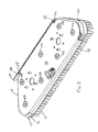
- FIG. 1 is bottom view of an exemplary floor cleaning machine having a coupling device embodying aspects of the present invention.
- FIG. 2 is a perspective view of a coupling device embodying aspects of the present invention, wherein the coupling device is coupled to a floor cleaning implement.
- FIG. 3 is a top view of the coupling device shown in FIG. 2 .
- FIG. 4 is a side view of the coupling device shown in FIG. 2 .
- FIG. 4A shows a first position of the cleaning implement coupled to the coupling device.
- FIG. 4B shows a second position of the cleaning implement coupled to the coupling device.
- FIG. 5 is a side cross-sectional view of the coupling device shown in FIG. 3 with the cross-section taken along line A-A.
- FIG. 5A corresponds to the position shown in FIG. 4A .
- FIG. 5B corresponds to the position shown in FIG. 4B .
- FIG. 6 is a front cross-sectional view of the coupling device shown in FIG. 3 with the cross-section taken along line B-B.
- FIG. 6A shows the cleaning implement coupled to the coupling device corresponding to the position shown in FIG. 4A .
- FIG. 6B shows the cleaning implement coupled to the coupling device corresponding to the position shown in FIG. 4B .
- FIG. 7 is a perspective top view of a brush type cleaning implement embodying aspects of the present invention.
- FIG. 8 is a perspective top view of a pad type cleaning implement embodying aspects of the present invention.
- a floor cleaning machine 10 comprising a device 12 used to couple cleaning implements 14 , such as scrubbing pads and brushes, to the cleaning machine 10 .
- cleaning implements 14 such as scrubbing pads and brushes
- FIG. 1 a floor cleaning machine 10 is shown, comprising a device 12 used to couple cleaning implements 14 , such as scrubbing pads and brushes, to the cleaning machine 10 .
- cleaning implements 14 such as scrubbing pads and brushes
- this illustrated coupling device 12 is adapted to move the cleaning implement 14 in an orbital or reciprocating motion.
- this illustrated coupling device 12 is adapted to move the cleaning implement 14 in an orbital or reciprocating motion.
- the principles shown herein can be adapted for rotary motion as well.
- the cleaning implement 14 and coupling device 12 are generally elongated due to the orbital motion of this cleaning device.
- the cleaning implement 14 can have a variety of other configurations, such as square, rectangular, circular, other polygonal shapes, and the like.
- FIGS. 7 and 8 Two particular embodiments of the cleaning implement 14 are shown in FIGS. 7 and 8 .
- FIG. 7 illustrates a brush type cleaning implement 14
- FIG. 8 illustrates a cleaning pad type cleaning implement 14
- both cleaning implements 14 have substantially similar fixation portions 16 that are used to couple the brush or pad to the coupling device 12 .
- the fixation portion 16 and the cleaning portion 18 of the illustrated embodiments are generally trapezoidal shaped, but other configurations are possible.
- the fixation portions 16 have a main body 20 having a first longitudinal edge 22 and a second longitudinal edge 24 positioned opposite the first longitudinal edge 22 .
- the first and second longitudinal edges 22 , 24 are slightly cantilevered over the cleaning element 18 .
- a plurality of locating members 26 are coupled to the top side of the fixation portion 16 .
- These locating members 26 can be made from a variety of materials and can be configured many different ways.
- the locating members 26 are rubber projections that have a generally convex shape. Specifically, the rubber projections have a dome-like or truncated cone configuration. As will be discussed below, this type of shape can help to locate or direct the locating members into receiving recesses 28 on the coupling device 12 .
- the projections 26 of this embodiment are formed of rubber to help dampen noise between the cleaning implement 14 and the coupling device 12 . Other materials, however, can be used for this same purpose.
- the illustrated embodiment places the projecting locating members 26 on the fixation portion 16 of the cleaning implement 14 and the receiving recesses 28 on the coupling device 12
- other embodiments can modify this configuration.
- the projections 26 can be placed on the coupling device 12
- the recesses 28 can be placed on the fixation portion 16 of the cleaning implement 14 .
- some embodiments can utilize a combination of projections 26 and recesses 28 on both the fixation portion 16 of the cleaning implement and the coupling device 12 .
- the cleaning implement 14 or more specifically, the fixation portion 16 of the cleaning implement 14 is received within the coupling device 12 to connect the cleaning implement 14 to the floor cleaning machine 10 .
- the coupling device 12 includes a main body 30 having a pair of slots or channels 32 for receiving the edges 22 , 24 of the fixation portion 16 of the cleaning implement 14 .
- the channels 32 are dimensioned and configured to receive the edges 22 , 24 of the fixation portion 16 . More specifically, as shown in FIGS. 4 and 5 , the channels 32 are dimensioned to allow the fixation portion 16 to easily slide into the coupling device 12 , without significant interference or engagement between the locating members 26 and the body 30 of the coupling device 12 .
- one of the channels 32 has a retainer 34 to selectively prevent the cleaning implement 14 from disengaging the coupling device 12 .
- the retainer 34 includes a projection 36 positioned adjacent one end of the channel 32 and intersecting the path defined by the channel 32 .
- the retainer 34 also includes another projection 38 positioned adjacent the other end of the channel 32 and intersecting the path defined by the channel 32 .
- At least one of the projections 36 , 38 is selectively moveable to a non-intersecting position to allow the cleaning implement 14 to be removed from the coupling device 12 .
- only one projection 38 is selectively moveable.
- This projection 38 is provided with a lever 40 to provide leverage for an operator to elastically deform the retainer 34 or otherwise move the projection 38 .
- the projection 38 located at this end is angled to allow a cleaning implement 14 to be inserted without manually moving the projection 38 with the lever 40 . Rather, due to the angled configuration of the projection 38 , the projection 38 will naturally be forced outward when engaged by the edge 22 of the fixation portion 16 of the cleaning implement 14 during insertion.
- the retainer 34 is formed separate from the channel 32 and is attached to the channel 32 in a secondary operation, such as welding.
- the retainer 34 can be integrally formed into the channel 32 or the main body portion 30 .
- the main body portion 30 of the coupling device 12 is provided with a plurality of recesses 28 .
- These recesses 28 are dimensioned and configured to selectively house or receive portions of the projections 26 extending from the top of the cleaning implement 14 .
- the recesses 28 have a generally concave configuration to receive the projections 26 .
- the generally concave recesses 28 have a dome-like configuration or some what conical configuration, much like the configuration of the projections 26 on the cleaning implement 14 .
- the recesses 28 are generally positioned and spaced apart in substantially the same configuration as the projections 26 on the cleaning implement 14 .
- a cleaning implement 14 such as the brush shown in FIG. 7 can be coupled to the floor cleaning machine 10 via the coupling device 12 shown in FIGS. 2-6 as follows.
- the cleaning implement 14 is aligned with the coupling device 12 .
- the cantilevered edges 22 , 24 of the fixation portion 16 of the cleaning implement 14 are aligned with the channels 32 of the coupling device 12 .
- the cleaning implement 14 can be inserted, pushed, driven, or otherwise forced into the channels 32 of the coupling device 12 .
- the bottom surface of the cantilevered edges 22 , 24 i.e., the surface facing the floor during operation
- the brush 14 should be easily inserted without the projections 26 on the brush interfering or substantially engaging the main body portion 30 of the coupling device 12 .
- the angled projection 38 can elastically return to its original position. In this position, the brush 14 is prevented from disengaging the coupling device 12 , and more specifically, the cantilevered edge is prevented from backing out of the channel 32 .
- the brush 14 Once the brush 14 is fully inserted in the coupling device 12 , it will rest within the coupling device 12 as shown in FIGS. 4A , 5 A, and 6 A. Specifically, the lower surface of the cantilevered edges 22 , 24 will rest on the lower portion of the channel 32 . Further, as shown in these figures, the projections 26 on top of the cleaning implement 14 will not be engaged with the recesses 28 of the coupling device 12 . However, the projections 26 may be substantially aligned with the recesses 28 in this position.
- the brush 14 and coupling device 12 When an operator chooses to utilize the brushes 14 , the brush 14 and coupling device 12 will be lowered into contact with a floor.
- An actuator such as a motor or motor and transmission assembly, can be used to lower the brush 14 and coupling device 12 to the floor.
- the actuator can be used to force the brush 14 against the floor with a desired pressure or force. This will cause the brush 14 to engage the coupling device 12 as shown in FIGS. 4A , 5 A, and 6 A.
- the projections 26 extending from the top of the brush 14 engage the recesses 28 on the main body portion 30 of the coupling device 12 . This engagement prevents the brush 14 from moving relative to the coupling device 12 when the brushes 14 are caused to actuate relative to the floor.
- the shape of the projections 26 and recesses 28 should encourage proper alignment and engagement.
- the generally convex shape of the projections 26 combined with the concave shape of the recesses 28 can funnel or otherwise move the brush into proper alignment with the coupling device 12 .
- the actuator can be actuated to lift the brush 14 and coupling device 12 off of the floor. Once the brush 14 is lifted off of the floor, the brush will rest within the coupling device 12 as shown in FIG. 4A .
- a force can be applied to the lever 40 adjacent the angled projection 38 to move the projection 38 to a position in which it does not substantially intersect the path defined by the channel 32 .
- the brush 14 can be removed from the coupling device 12 by pulling it in the opposite direction that it was inserted.
Abstract
Description
Claims (20)
Priority Applications (1)
| Application Number | Priority Date | Filing Date | Title |
|---|---|---|---|
| US12/162,407 US8091171B2 (en) | 2006-02-01 | 2007-02-01 | Device and method for coupling a cleaning implement to a floor cleaning machine |
Applications Claiming Priority (3)
| Application Number | Priority Date | Filing Date | Title |
|---|---|---|---|
| US76431606P | 2006-02-01 | 2006-02-01 | |
| US12/162,407 US8091171B2 (en) | 2006-02-01 | 2007-02-01 | Device and method for coupling a cleaning implement to a floor cleaning machine |
| PCT/US2007/061439 WO2007090183A2 (en) | 2006-02-01 | 2007-02-01 | Device and method for coupling a cleaning implement to a floor cleaning machine |
Related Parent Applications (2)
| Application Number | Title | Priority Date | Filing Date |
|---|---|---|---|
| US76431606P Substitution | 2006-02-01 | 2006-02-01 | |
| PCT/US2007/061439 A-371-Of-International WO2007090183A2 (en) | 2006-02-01 | 2007-02-01 | Device and method for coupling a cleaning implement to a floor cleaning machine |
Related Child Applications (1)
| Application Number | Title | Priority Date | Filing Date |
|---|---|---|---|
| US13/346,365 Continuation US8387199B2 (en) | 2006-02-01 | 2012-01-09 | Device and method for coupling a cleaning implement to a floor cleaning machine |
Publications (2)
| Publication Number | Publication Date |
|---|---|
| US20100000034A1 US20100000034A1 (en) | 2010-01-07 |
| US8091171B2 true US8091171B2 (en) | 2012-01-10 |
Family
ID=38328159
Family Applications (3)
| Application Number | Title | Priority Date | Filing Date |
|---|---|---|---|
| US12/162,407 Expired - Fee Related US8091171B2 (en) | 2006-02-01 | 2007-02-01 | Device and method for coupling a cleaning implement to a floor cleaning machine |
| US13/346,365 Expired - Fee Related US8387199B2 (en) | 2006-02-01 | 2012-01-09 | Device and method for coupling a cleaning implement to a floor cleaning machine |
| US13/785,278 Abandoned US20130192009A1 (en) | 2006-02-01 | 2013-03-05 | Device and method for coupling a cleaning implement to a floor cleaning machine |
Family Applications After (2)
| Application Number | Title | Priority Date | Filing Date |
|---|---|---|---|
| US13/346,365 Expired - Fee Related US8387199B2 (en) | 2006-02-01 | 2012-01-09 | Device and method for coupling a cleaning implement to a floor cleaning machine |
| US13/785,278 Abandoned US20130192009A1 (en) | 2006-02-01 | 2013-03-05 | Device and method for coupling a cleaning implement to a floor cleaning machine |
Country Status (6)
| Country | Link |
|---|---|
| US (3) | US8091171B2 (en) |
| EP (1) | EP1988808B1 (en) |
| JP (1) | JP4987883B2 (en) |
| CA (1) | CA2640740C (en) |
| DK (1) | DK1988808T3 (en) |
| WO (1) | WO2007090183A2 (en) |
Cited By (1)
| Publication number | Priority date | Publication date | Assignee | Title |
|---|---|---|---|---|
| US5677339A (en) * | 1986-12-23 | 1997-10-14 | Tristrata Technology, Inc. | Method of using mandelic acid for treating wrinkles |
Families Citing this family (4)
| Publication number | Priority date | Publication date | Assignee | Title |
|---|---|---|---|---|
| US10065093B2 (en) * | 2010-04-15 | 2018-09-04 | Clarence K. Cohens | Cat's claw golf tool with tread cleaning |
| CN108526835B (en) * | 2018-03-31 | 2019-11-26 | 浙江胜华眼镜有限公司 | A kind of besom assembling equipment |
| CN108655729B (en) * | 2018-05-23 | 2020-06-09 | 周影雪 | Side brush assembling equipment of floor sweeping robot |
| CN112741560B (en) * | 2020-12-30 | 2022-04-29 | 永康市宏奥工贸有限公司 | Ground cleaning device for cleaning robot |
Citations (12)
| Publication number | Priority date | Publication date | Assignee | Title |
|---|---|---|---|---|
| US3115660A (en) | 1962-07-09 | 1963-12-31 | Donald L Hunt | Adapter for portable motor driven floor maintaining machines |
| US3216035A (en) * | 1963-07-11 | 1965-11-09 | Electrolux Ab | Surface treating apparatus |
| US3996639A (en) | 1975-08-28 | 1976-12-14 | Griffin Dana K | Dust mop with peel-off mop head |
| US5398366A (en) * | 1991-03-29 | 1995-03-21 | Bradley; Terry | Rocker toothbrush |
| US5419007A (en) | 1993-12-16 | 1995-05-30 | Emerson Electric Co. | Snap together wet nozzle |
| US5806132A (en) | 1995-05-23 | 1998-09-15 | The Malish Corporation | Locking coupler for floor maintenance pad |
| DE19728927A1 (en) | 1997-05-02 | 1998-11-05 | Vorwerk Co Interholding | Floor care equipment |
| US6032313A (en) | 1995-05-26 | 2000-03-07 | Tsang; Koon Keung | Household appliance having plural coaxially rotatable or parallel linearly movable heads or tools |
| US20040187238A1 (en) * | 2003-03-31 | 2004-09-30 | Ty Holdings Llc | Baseboard corner and edge cleaning machine |
| USD546007S1 (en) * | 2005-12-13 | 2007-07-03 | Johnsondiversey, Inc. | Floor scrubbing pad adapted for use on a floor scrubbing machine |
| USD556403S1 (en) * | 2005-12-20 | 2007-11-27 | Johnsondiversey, Inc. | Floor scrubbing brush adapted for use on a floor scrubbing machine |
| USD602660S1 (en) * | 2007-09-17 | 2009-10-20 | Johnsondiversey, Inc. | Mount for floor scrubbing implement |
Family Cites Families (10)
| Publication number | Priority date | Publication date | Assignee | Title |
|---|---|---|---|---|
| NL40446B (en) * | 1926-11-27 | |||
| US3423781A (en) * | 1967-10-25 | 1969-01-28 | Harry H Henson | Securement for mop or broom heads |
| US3600735A (en) * | 1970-01-26 | 1971-08-24 | Dustbane Enterprises Ltd | Floor polisher drive connection |
| US4419007A (en) | 1982-06-14 | 1983-12-06 | Xerox Corporation | Multi-mode document handling system |
| JPH03103066A (en) | 1989-09-18 | 1991-04-30 | Fujitsu Ltd | Power source interruption detector |
| JPH0740359Y2 (en) * | 1990-02-08 | 1995-09-20 | 花王株式会社 | Cleaning tool |
| JPH08131387A (en) * | 1994-11-10 | 1996-05-28 | Lion Corp | Cleaning device |
| DE19606107C1 (en) | 1996-02-19 | 1997-02-13 | Martin Umwelt & Energietech | Firing grate, in particular for waste incineration plants |
| US6647578B2 (en) * | 2001-09-18 | 2003-11-18 | The Hoover Company | Brush assembly removal device |
| DE602004002849T2 (en) * | 2004-05-07 | 2007-01-25 | JohnsonDiversey, Inc., Sturtevant | Soil treatment and cleaning system |
-
2007
- 2007-02-01 CA CA2640740A patent/CA2640740C/en not_active Expired - Fee Related
- 2007-02-01 US US12/162,407 patent/US8091171B2/en not_active Expired - Fee Related
- 2007-02-01 DK DK07717507.3T patent/DK1988808T3/en active
- 2007-02-01 JP JP2008553498A patent/JP4987883B2/en not_active Expired - Fee Related
- 2007-02-01 EP EP07717507.3A patent/EP1988808B1/en not_active Not-in-force
- 2007-02-01 WO PCT/US2007/061439 patent/WO2007090183A2/en active Application Filing
-
2012
- 2012-01-09 US US13/346,365 patent/US8387199B2/en not_active Expired - Fee Related
-
2013
- 2013-03-05 US US13/785,278 patent/US20130192009A1/en not_active Abandoned
Patent Citations (12)
| Publication number | Priority date | Publication date | Assignee | Title |
|---|---|---|---|---|
| US3115660A (en) | 1962-07-09 | 1963-12-31 | Donald L Hunt | Adapter for portable motor driven floor maintaining machines |
| US3216035A (en) * | 1963-07-11 | 1965-11-09 | Electrolux Ab | Surface treating apparatus |
| US3996639A (en) | 1975-08-28 | 1976-12-14 | Griffin Dana K | Dust mop with peel-off mop head |
| US5398366A (en) * | 1991-03-29 | 1995-03-21 | Bradley; Terry | Rocker toothbrush |
| US5419007A (en) | 1993-12-16 | 1995-05-30 | Emerson Electric Co. | Snap together wet nozzle |
| US5806132A (en) | 1995-05-23 | 1998-09-15 | The Malish Corporation | Locking coupler for floor maintenance pad |
| US6032313A (en) | 1995-05-26 | 2000-03-07 | Tsang; Koon Keung | Household appliance having plural coaxially rotatable or parallel linearly movable heads or tools |
| DE19728927A1 (en) | 1997-05-02 | 1998-11-05 | Vorwerk Co Interholding | Floor care equipment |
| US20040187238A1 (en) * | 2003-03-31 | 2004-09-30 | Ty Holdings Llc | Baseboard corner and edge cleaning machine |
| USD546007S1 (en) * | 2005-12-13 | 2007-07-03 | Johnsondiversey, Inc. | Floor scrubbing pad adapted for use on a floor scrubbing machine |
| USD556403S1 (en) * | 2005-12-20 | 2007-11-27 | Johnsondiversey, Inc. | Floor scrubbing brush adapted for use on a floor scrubbing machine |
| USD602660S1 (en) * | 2007-09-17 | 2009-10-20 | Johnsondiversey, Inc. | Mount for floor scrubbing implement |
Non-Patent Citations (1)
| Title |
|---|
| The International Search Report from the European Patent Office, Oct. 9, 2007. |
Cited By (1)
| Publication number | Priority date | Publication date | Assignee | Title |
|---|---|---|---|---|
| US5677339A (en) * | 1986-12-23 | 1997-10-14 | Tristrata Technology, Inc. | Method of using mandelic acid for treating wrinkles |
Also Published As
| Publication number | Publication date |
|---|---|
| CA2640740C (en) | 2010-09-21 |
| CA2640740A1 (en) | 2007-08-09 |
| WO2007090183A3 (en) | 2007-12-13 |
| EP1988808A2 (en) | 2008-11-12 |
| US20100000034A1 (en) | 2010-01-07 |
| WO2007090183A2 (en) | 2007-08-09 |
| JP2009525159A (en) | 2009-07-09 |
| DK1988808T3 (en) | 2014-08-11 |
| JP4987883B2 (en) | 2012-07-25 |
| US20130192009A1 (en) | 2013-08-01 |
| US8387199B2 (en) | 2013-03-05 |
| EP1988808B1 (en) | 2014-05-07 |
| US20120174329A1 (en) | 2012-07-12 |
Similar Documents
| Publication | Publication Date | Title |
|---|---|---|
| US8387199B2 (en) | Device and method for coupling a cleaning implement to a floor cleaning machine | |
| US8166597B2 (en) | Flat mop with abrasive pad | |
| US5915437A (en) | Mop bonnet clip | |
| US7779501B2 (en) | Mop having scrubbing area | |
| US7204745B2 (en) | Device in a circular, disk-shaped element intended for cleaning purposes | |
| US5392491A (en) | Cleaner head for a vacuum cleaner | |
| JP2007054337A (en) | Head for cleaning and cleaning tool | |
| CN109414144A (en) | Surface maintenance machine with quick pop-up maintenance tool component | |
| EP2814370B1 (en) | Surface maintenance vehicle with quick release squeegee assembly | |
| US5361442A (en) | Pool tile scrubber | |
| EP2000071A2 (en) | Vacuum cleaner apparatus of versatile type for cleaning surfaces of various kind and hardness | |
| JPH10248779A (en) | Suction tool for vacuum cleaner provided with wiping function | |
| KR20060115109A (en) | Small sized robot vacuum cleaner | |
| JP2001238840A (en) | Cleaning tool | |
| JP3191904B2 (en) | Vacuum cleaner suction tool | |
| WO1994020010A1 (en) | Suction head for a floor cleaning machine | |
| JP2000318965A (en) | Cleaning method and device for escalator | |
| CN219270827U (en) | Cleaning unit and cleaning device | |
| JPH04317619A (en) | Cleaning machine | |
| US20240058924A1 (en) | Towel Quick Connector Cleaning Wand | |
| JPH0938011A (en) | Cleaner nozzle with mop | |
| US20130117964A1 (en) | Aspiration nozzle of vacuum cleaner and vacuum cleaner having same | |
| CN115040036A (en) | Floor mopping mechanism, cleaning device and cleaning device control method | |
| JP2009234735A (en) | Passenger conveyor device and oil pan cleaning device | |
| JP2000318966A (en) | Cleaning method and cleaning device of escalator |
Legal Events
| Date | Code | Title | Description |
|---|---|---|---|
| AS | Assignment |
Owner name: CITIBANK, N.A., AS ADMINISTRATIVE AGENT,NEW YORK Free format text: SECURITY AGREEMENT;ASSIGNOR:JOHNSONDIVERSEY, INC.;REEL/FRAME:023814/0701 Effective date: 20091124 Owner name: CITIBANK, N.A., AS ADMINISTRATIVE AGENT, NEW YORK Free format text: SECURITY AGREEMENT;ASSIGNOR:JOHNSONDIVERSEY, INC.;REEL/FRAME:023814/0701 Effective date: 20091124 |
|
| AS | Assignment |
Owner name: DIVERSEY, INC.,WISCONSIN Free format text: CHANGE OF NAME;ASSIGNOR:JOHNSONDIVERSEY, INC.;REEL/FRAME:024079/0021 Effective date: 20100301 Owner name: DIVERSEY, INC., WISCONSIN Free format text: CHANGE OF NAME;ASSIGNOR:JOHNSONDIVERSEY, INC.;REEL/FRAME:024079/0021 Effective date: 20100301 |
|
| AS | Assignment |
Owner name: DIVERSEY, INC. (FORMERLY KNOWN AS JOHNSONDIVERSEY, Free format text: RELEASE BY SECURED PARTY;ASSIGNOR:CITIBANK, N.A., AS ADMINISTRATIVE AGENT;REEL/FRAME:027618/0044 Effective date: 20111003 |
|
| AS | Assignment |
Owner name: JOHNSONDIVERSEY, INC., WISCONSIN Free format text: ASSIGNMENT OF ASSIGNORS INTEREST;ASSIGNORS:MAYER, HEINRICH-TITO;OBERHAENSLI, FRANZ;SIGNING DATES FROM 20070113 TO 20070130;REEL/FRAME:029587/0023 |
|
| REMI | Maintenance fee reminder mailed | ||
| LAPS | Lapse for failure to pay maintenance fees | ||
| STCH | Information on status: patent discontinuation |
Free format text: PATENT EXPIRED DUE TO NONPAYMENT OF MAINTENANCE FEES UNDER 37 CFR 1.362 |
|
| FP | Lapsed due to failure to pay maintenance fee |
Effective date: 20160110 |