US8080833B2 - Thick pseudomorphic nitride epitaxial layers - Google Patents
Thick pseudomorphic nitride epitaxial layers Download PDFInfo
- Publication number
- US8080833B2 US8080833B2 US12/764,584 US76458410A US8080833B2 US 8080833 B2 US8080833 B2 US 8080833B2 US 76458410 A US76458410 A US 76458410A US 8080833 B2 US8080833 B2 US 8080833B2
- Authority
- US
- United States
- Prior art keywords
- layer
- substrate
- approximately
- relaxed
- semiconductor layer
- Prior art date
- Legal status (The legal status is an assumption and is not a legal conclusion. Google has not performed a legal analysis and makes no representation as to the accuracy of the status listed.)
- Active
Links
Images


Classifications
-
- H—ELECTRICITY
- H01—ELECTRIC ELEMENTS
- H01L—SEMICONDUCTOR DEVICES NOT COVERED BY CLASS H10
- H01L21/00—Processes or apparatus adapted for the manufacture or treatment of semiconductor or solid state devices or of parts thereof
- H01L21/02—Manufacture or treatment of semiconductor devices or of parts thereof
- H01L21/02104—Forming layers
- H01L21/02365—Forming inorganic semiconducting materials on a substrate
- H01L21/02518—Deposited layers
- H01L21/02521—Materials
- H01L21/02538—Group 13/15 materials
- H01L21/0254—Nitrides
-
- H—ELECTRICITY
- H01—ELECTRIC ELEMENTS
- H01L—SEMICONDUCTOR DEVICES NOT COVERED BY CLASS H10
- H01L21/00—Processes or apparatus adapted for the manufacture or treatment of semiconductor or solid state devices or of parts thereof
- H01L21/02—Manufacture or treatment of semiconductor devices or of parts thereof
- H01L21/02104—Forming layers
- H01L21/02365—Forming inorganic semiconducting materials on a substrate
- H01L21/02367—Substrates
- H01L21/0237—Materials
- H01L21/02387—Group 13/15 materials
- H01L21/02389—Nitrides
-
- H—ELECTRICITY
- H01—ELECTRIC ELEMENTS
- H01L—SEMICONDUCTOR DEVICES NOT COVERED BY CLASS H10
- H01L21/00—Processes or apparatus adapted for the manufacture or treatment of semiconductor or solid state devices or of parts thereof
- H01L21/02—Manufacture or treatment of semiconductor devices or of parts thereof
- H01L21/02104—Forming layers
- H01L21/02365—Forming inorganic semiconducting materials on a substrate
- H01L21/02367—Substrates
- H01L21/02433—Crystal orientation
-
- H—ELECTRICITY
- H01—ELECTRIC ELEMENTS
- H01L—SEMICONDUCTOR DEVICES NOT COVERED BY CLASS H10
- H01L21/00—Processes or apparatus adapted for the manufacture or treatment of semiconductor or solid state devices or of parts thereof
- H01L21/02—Manufacture or treatment of semiconductor devices or of parts thereof
- H01L21/02104—Forming layers
- H01L21/02365—Forming inorganic semiconducting materials on a substrate
- H01L21/02436—Intermediate layers between substrates and deposited layers
- H01L21/02439—Materials
- H01L21/02455—Group 13/15 materials
- H01L21/02458—Nitrides
-
- H—ELECTRICITY
- H01—ELECTRIC ELEMENTS
- H01L—SEMICONDUCTOR DEVICES NOT COVERED BY CLASS H10
- H01L21/00—Processes or apparatus adapted for the manufacture or treatment of semiconductor or solid state devices or of parts thereof
- H01L21/02—Manufacture or treatment of semiconductor devices or of parts thereof
- H01L21/02104—Forming layers
- H01L21/02365—Forming inorganic semiconducting materials on a substrate
- H01L21/02612—Formation types
- H01L21/02617—Deposition types
- H01L21/0262—Reduction or decomposition of gaseous compounds, e.g. CVD
-
- H—ELECTRICITY
- H01—ELECTRIC ELEMENTS
- H01L—SEMICONDUCTOR DEVICES NOT COVERED BY CLASS H10
- H01L33/00—Semiconductor devices with at least one potential-jump barrier or surface barrier specially adapted for light emission; Processes or apparatus specially adapted for the manufacture or treatment thereof or of parts thereof; Details thereof
- H01L33/02—Semiconductor devices with at least one potential-jump barrier or surface barrier specially adapted for light emission; Processes or apparatus specially adapted for the manufacture or treatment thereof or of parts thereof; Details thereof characterised by the semiconductor bodies
- H01L33/12—Semiconductor devices with at least one potential-jump barrier or surface barrier specially adapted for light emission; Processes or apparatus specially adapted for the manufacture or treatment thereof or of parts thereof; Details thereof characterised by the semiconductor bodies with a stress relaxation structure, e.g. buffer layer
-
- H—ELECTRICITY
- H01—ELECTRIC ELEMENTS
- H01L—SEMICONDUCTOR DEVICES NOT COVERED BY CLASS H10
- H01L33/00—Semiconductor devices with at least one potential-jump barrier or surface barrier specially adapted for light emission; Processes or apparatus specially adapted for the manufacture or treatment thereof or of parts thereof; Details thereof
- H01L33/02—Semiconductor devices with at least one potential-jump barrier or surface barrier specially adapted for light emission; Processes or apparatus specially adapted for the manufacture or treatment thereof or of parts thereof; Details thereof characterised by the semiconductor bodies
- H01L33/025—Physical imperfections, e.g. particular concentration or distribution of impurities
-
- H—ELECTRICITY
- H01—ELECTRIC ELEMENTS
- H01L—SEMICONDUCTOR DEVICES NOT COVERED BY CLASS H10
- H01L33/00—Semiconductor devices with at least one potential-jump barrier or surface barrier specially adapted for light emission; Processes or apparatus specially adapted for the manufacture or treatment thereof or of parts thereof; Details thereof
- H01L33/02—Semiconductor devices with at least one potential-jump barrier or surface barrier specially adapted for light emission; Processes or apparatus specially adapted for the manufacture or treatment thereof or of parts thereof; Details thereof characterised by the semiconductor bodies
- H01L33/08—Semiconductor devices with at least one potential-jump barrier or surface barrier specially adapted for light emission; Processes or apparatus specially adapted for the manufacture or treatment thereof or of parts thereof; Details thereof characterised by the semiconductor bodies with a plurality of light emitting regions, e.g. laterally discontinuous light emitting layer or photoluminescent region integrated within the semiconductor body
-
- H—ELECTRICITY
- H01—ELECTRIC ELEMENTS
- H01L—SEMICONDUCTOR DEVICES NOT COVERED BY CLASS H10
- H01L33/00—Semiconductor devices with at least one potential-jump barrier or surface barrier specially adapted for light emission; Processes or apparatus specially adapted for the manufacture or treatment thereof or of parts thereof; Details thereof
- H01L33/02—Semiconductor devices with at least one potential-jump barrier or surface barrier specially adapted for light emission; Processes or apparatus specially adapted for the manufacture or treatment thereof or of parts thereof; Details thereof characterised by the semiconductor bodies
- H01L33/20—Semiconductor devices with at least one potential-jump barrier or surface barrier specially adapted for light emission; Processes or apparatus specially adapted for the manufacture or treatment thereof or of parts thereof; Details thereof characterised by the semiconductor bodies with a particular shape, e.g. curved or truncated substrate
- H01L33/22—Roughened surfaces, e.g. at the interface between epitaxial layers
-
- H—ELECTRICITY
- H01—ELECTRIC ELEMENTS
- H01L—SEMICONDUCTOR DEVICES NOT COVERED BY CLASS H10
- H01L33/00—Semiconductor devices with at least one potential-jump barrier or surface barrier specially adapted for light emission; Processes or apparatus specially adapted for the manufacture or treatment thereof or of parts thereof; Details thereof
- H01L33/02—Semiconductor devices with at least one potential-jump barrier or surface barrier specially adapted for light emission; Processes or apparatus specially adapted for the manufacture or treatment thereof or of parts thereof; Details thereof characterised by the semiconductor bodies
- H01L33/26—Materials of the light emitting region
- H01L33/30—Materials of the light emitting region containing only elements of group III and group V of the periodic system
- H01L33/32—Materials of the light emitting region containing only elements of group III and group V of the periodic system containing nitrogen
Definitions
- the technology disclosed herein relates generally to lattice-mismatched semiconductor heterostructures, in particular pseudomorphic layers having a thickness greater than the critical thickness predicted therefor.
- Achieving low defect densities throughout a semiconductor active device layer is important for the fabrication of a commercially practical nitride-based semiconductor device.
- the '660 application the entire disclosure of which is hereby incorporated by reference, it is possible to form large-diameter, low-defect-density AlN substrates.
- many desirable device applications preferably incorporate device layers based on alloys of AlN, GaN, and InN to be grown on the AlN substrate. As the concentration of GaN and InN is increased, the lattice mismatch with respect to the AlN substrate also increases.
- the lattice parameter in the c-plane of GaN is approximately 2.4% larger than that of AlN.
- the initial layer typically grows pseudomorphically—that is, the epitaxial layer will be compressed (experience compressive strain) in the plane of the substrate surface if the intrinsic lattice parameter of the substrate is smaller than that of the epitaxial layer.
- the epitaxial layer will be stretched or put under tensile strain when the intrinsic lattice parameter of the epitaxial layer is smaller than that of the substrate.
- the strain energy in the epitaxial layer will grow and, typically, the layer will find some way to reduce the strain energy. This may occur by plastic flow through the motion of dislocations, through the creation of surface morphological features which allow strain relaxation, or, particularly when the strain is tensile, through cracking of the film.
- the pseudomorphic epitaxial layer may also be grown with very low dislocation densities, often with the same dislocation density as the substrate.
- the second advantage accrues from the ability to tailor the band structure through the large resulting biaxial strains. For example, the strain can be used to break the degeneracy between heavy and light carrier bands and, as a result, obtain higher carrier mobilities.
- pseudomorphic layers may be insufficient for the fabrication of high-output-power light-emitting devices such as light-emitting diodes (LEDs) and lasers.
- LEDs light-emitting diodes
- Such devices are generally sensitive to strain-relieving defects, placing constraints on not only the light-emitting active layer(s) (which are generally one or more strained quantum wells), but also adjoining layers, as defects in adjoining layers may propagate through the active layer(s) even if the active layer(s) remain pseudomorphically strained.
- adjoining layers generally require particular thicknesses and/or compositions to enable, e.g., adequate electrical contact to the device, if these layers are maintained in a pseudomorphic state, the allowable thickness for the active layer(s) (in order to maintain the entire “stack” of layers in a pseudomorphic state) may be diminished, thus decreasing the potential output power of the finished device.
- such layers may require high doping levels to enable low-resistance contacts to the device, and compositions closely lattice-matched with device active layers and/or the underlying substrate may be difficult to dope at high levels.
- a technique is provided for growing very thick pseudomorphic films of alloys of AlN, GaN, and InN on high-quality AlN substrates.
- a pseudomorphic film is one where the strain parallel to the interface is approximately that needed to distort the lattice in the film to match that of the substrate.
- the parallel strain in a pseudomorphic film will be nearly or approximately equal to the difference in lattice parameters between an unstrained substrate parallel to the interface and an unstrained epitaxial layer parallel to the interface.
- very thick refers to a thickness of the epitaxial layer that substantially exceeds (by a factor of at least 5 for substantially In-free layers or by a factor of at least 10 for layers including In) the expected critical thickness for the epitaxial film based on standard calculations of the thickness where strain relaxation should start to occur through the nucleation and/or motion of threading dislocations (or energy equilibrium calculations).
- the expected critical thickness may be calculated as described in, e.g., Matthews and Blakeslee, J. Crystal Growth 27, 118 (1974), and/or U.S. Pat. No. 4,088,515, the entire disclosure of each being hereby incorporated by reference.
- the pseudomorphic layers are utilized as active layers of light-emitting devices such as LEDs and lasers, thus enabling fabrication of such devices having high output power.
- the electrical properties of the devices are optimized, via maximization of the thickness of the pseudomorphic active layers, by intentional relaxation of other layers in the device.
- the intentional relaxation performed by, e.g., deposition of at least a portion of the layer in a substantially islanded growth mode, is performed only in layers contributing to majority carrier transport (i.e., not minority carrier transport, which is vastly more sensitive to defects) and in regions where resulting strain-relieving defects do not intersect the active layer(s).
- the thickness of the pseudomorphic active layers and other layers may be maximized, increasing output power and efficiency while decreasing contact resistance.
- embodiments of the invention feature a semiconductor device including or consisting essentially of an aluminum nitride single-crystal substrate, at least one pseudomorphic strained layer disposed thereover, and, disposed over the strained layer(s), a semiconductor layer that is lattice-mismatched to the substrate and substantially relaxed.
- the at least one strained layer may include or consist essentially of AlN, GaN, InN, and/or an alloy thereof.
- An array of misfit dislocations may be disposed at the interface between the strained layer and the semiconductor layer.
- Embodiments of the invention may include one or more of the following in any of a variety of combinations.
- the relaxed semiconductor layer may include a plurality of defects that do not propagate into the at least one strained layer.
- a metal contact layer may be disposed over the relaxed semiconductor layer.
- the relaxed semiconductor layer may include or consist essentially of gallium nitride, e.g., p-type-doped gallium nitride.
- the relaxed semiconductor layer may be p-type doped to a hole concentration at room temperature ranging between approximately 1 ⁇ 10 17 /cm 3 and approximately 1 ⁇ 10 20 /cm 3 .
- the at least one strained layer may have a thickness exceeding the predicted critical thickness associated therewith by at least a factor of 5, the predicted critical thickness being calculated with the Matthews-Blakeslee theory.
- the thickness of the at least one strained layer may exceed the predicted critical thickness by at least a factor of 10.
- a pattern including or consisting essentially of a plurality of cones may be disposed on the bottom surface of the substrate. Each of the plurality of cones may have an apex angle of approximately 26°.
- the defect density of the relaxed semiconductor layer may be at least two orders of magnitude, or even at least five orders of magnitude, larger than the defect density of the substrate.
- embodiments of the invention feature a method of forming a semiconductor device.
- At least one pseudomorphic strained layer is formed over a single-crystal substrate, the strained layer(s) including or consisting essentially of AlN, GaN, InN, and/or an alloy thereof.
- a semiconductor layer that is lattice-mismatched to the substrate and substantially relaxed is formed over the at least one strained layer without (i) relaxing the at least one strained layer, and (ii) propagation of defects from the semiconductor layer into the at least one strained layer.
- An array of misfit dislocations may be formed at the interface between the relaxed semiconductor layer and the at least one strained layer.
- Embodiments of the invention may include one or more of the following in any of a variety of combinations.
- the at least one strained layer may have a thickness exceeding the predicted critical thickness associated therewith by at least a factor of 5, the predicted critical thickness being calculated with the Matthews-Blakeslee theory.
- the thickness of the at least one strained layer may exceed the predicted critical thickness by at least a factor of 10.
- a metal contact layer may be formed over the relaxed semiconductor layer.
- the substrate may include or consist essentially of aluminum nitride, and the relaxed semiconductor layer may include or consist essentially of gallium nitride. Forming the semiconductor layer may include or consist essentially of forming at least a portion of the relaxed semiconductor layer as a series of islands.
- the thickness of the semiconductor layer may be increased such that the series of islands coalesces into a unified layer.
- the at least one strained layer and the relaxed semiconductor layer may both be formed by epitaxial deposition.
- a pattern of cones may be formed, e.g., by etching, on the back surface of the substrate. At least a portion of the substrate may be removed, e.g., by grinding or polishing.
- FIG. 1 is a graph of predicted critical thickness and pseudomorphic strain for Al x Ga 1-x N layers of various Al contents x formed on AlN substrates;
- FIG. 2 is a schematic depicting a pseudomorphic strained layer formed on a substrate
- FIGS. 3A , 3 B, and 3 C are schematics of pseudomorphic strained layer-based device structures.
- FIGS. 4A , 4 B and 4 C are schematics of processed devices utilizing the layer structure of FIG. 3A or 3 C.
- the term “high quality” refers to epitaxial layers having a threading dislocation density of approximately 10 6 cm ⁇ 2 or less. In certain embodiments, 10 4 cm ⁇ 2 or less, or even approximately 10 2 cm ⁇ 2 or less.
- the term “pseudomorphic” is utilized herein to refer to epitaxial layers strained to at least approximately 80% of a lattice parameter of an underlying substrate (i.e., less than approximately 20% relaxed to its innate lattice parameter).
- a pseudomorphic layer may be approximately fully strained to the lattice parameter of the underlying substrate.
- the term “mirror smooth” refers to layer root-mean-squared (“RMS”) surface roughnesses less than approximately 5 nm in a 5 ⁇ m ⁇ 5 ⁇ m area (as measured by an atomic-force microscope). In preferred embodiments the RMS surface roughness is less than approximately 1 nm in a 5 ⁇ m ⁇ 5 ⁇ m area.
- a thick pseudomorphic semiconductor layer fabricated in accordance herewith is shown in FIG. 2 .
- a semiconductor substrate 200 is provided.
- semiconductor substrate 200 includes or consists essentially of AlN.
- the top surface 210 of semiconductor substrate 200 may be prepared for epitaxial growth by at least one of planarization (e.g., by chemical-mechanical polishing) or cleaning prior to deposition of one or more epitaxial layers thereon.
- a strained epitaxial layer 220 is then deposited on semiconductor substrate 200 , e.g., by organometallic vapor-phase epitaxy, to a thickness exceeding its predicted critical thickness. As can be seen in FIG.
- the predicted critical thickness of an exemplary epitaxial layer 220 consisting of Al x Ga 1-x N grown on a semiconductor substrate 200 consisting of AlN depends on the Al content x.
- the thickness of epitaxial layer 220 exceeds its predicted critical thickness by at least a factor of 5, or even by at least a factor of 10, and epitaxial layer 220 remains pseudomorphic.
- the thickness of epitaxial layer 220 may even exceed its predicted critical thickness by a factor of 20 or more.
- epitaxial layer 220 may actually consist of a plurality of discrete layers, each one pseudomorphically strained to the lattice parameter of semiconductor substrate 200 .
- the plurality of layers may include layers with graded composition, e.g., layers including AlN, InN, and/or GaN in which the concentration of one or more of the group III atoms changes with thickness. Such layers may be graded in discrete steps or linearly in composition.
- Strained epitaxial layer 220 may also be deposited on an optional relaxed semiconductor layer (not shown) formed over semiconductor substrate 200 .
- the strain in epitaxial layer 220 and the predicted critical thickness therefor will be a function of the lattice parameter of the relaxed semiconductor layer rather than that of semiconductor substrate 200 .
- Epitaxial layer 220 remains pseudomorphic, and the thickness of epitaxial layer 220 exceeds this predicted critical thickness by at least a factor of 5. In certain embodiments, the thickness of epitaxial layer 220 exceeds this predicted critical thickness by at least a factor of 10 or even at least a factor of 20.
- either semiconductor substrate 200 or the optional relaxed semiconductor layer can act as a relaxed “platform” to which epitaxial layer 220 is strained.
- TDD threading dislocation density
- Defects at the surface of the semiconductor substrate 200 may also cause roughening of epitaxial layer 220 .
- roughening occurs, strain relaxation occurs at the sidewalls of terraces and islands on the epitaxial surface. When these terraces and islands coalesce, they may deleteriously form high densities of threading dislocations at the coalescence boundaries.
- step-flow growth during the epitaxial deposition aids the prevention of relaxation, and the proper conditions for step-flow growth depend on the substrate orientation of the semiconductor substrate 200 .
- substrates are very closely oriented to on-axis (i.e., the surface normal of the substrate is very closely aligned to a major crystallographic axis)
- the density of steps across the surface of the substrate is low.
- incoming Al, Ga, or In atoms must diffusive relatively large distances to incorporate into the growing epitaxial layer at a step edge, i.e., maintain step-flow growth.
- step-flow growth may be maintained by (i) enhancing the long-distance diffusion of incoming atoms of the growth species and/or (ii) reducing the diffusion distance required to reach a step edge (i.e., increase the step density on the surface).
- Such long-distance diffusion may be enhanced by performing the epitaxial growth at higher temperatures (i.e., up to approximately 1100° C. or, in the case of In-free, high Al content (e.g., greater than approximately 50% Al content), by increasing the growth temperature to a range of greater than approximately 1100° C. to approximately 1300° C.
- long-distance diffusion may also be enhanced by decreasing the ratio of the nitrogen species (i.e., the group V species) in the epitaxial reactor in comparison to the group III species.
- a V-III ratio beneficial for enhancing long-distance diffusion of the growth species is less than approximately 1,000, and may even be less than approximately 10.
- the density of step edges on semiconductor substrate 200 may also be increased (thus reducing the required diffusion distances required to reach a step) by increasing the misorientation between the major crystallographic axis and the surface normal of the substrate.
- the misorientation of semiconductor substrate 200 ranges between approximately 0.5° and approximately 2°, e.g., approximately 1°.
- Kinetic barriers to strain relaxation may also be beneficially utilized to produce thick pseudomorphic epitaxial layers. Since any alloy of AlN, GaN, and InN (with nonzero content of either GaN or InN) will have a larger relaxed lattice parameter than an underlying AlN substrate, these epitaxial films will typically not relax by cracking. Relaxation may occur by the formation of misfit dislocations which run parallel to the interface between the AlN substrate and epitaxial alloy layer. These misfit dislocations may either result from the motion of existing threading dislocations which propagate into epitaxial layer 220 from semiconductor substrate 200 , or from new dislocation loops forming either from the surface or from some macroscopic defect on the surface of substrate 200 .
- semiconductor substrate 200 has a threading dislocation density less than approximately 10 6 cm ⁇ 2 . In other embodiments, semiconductor substrate 200 has a threading dislocation density less than approximately 10 4 cm ⁇ 2 or even less than approximately 10 2 cm ⁇ 2 . Semiconductor substrate 200 may also have a density of particulate surface defects less than approximately 100 cm ⁇ 2 . Utilization of such optimized semiconductor substrates minimizes or eliminates glide of existing dislocations and dislocation nucleation at surface defects as relaxation mechanisms.
- the remaining relaxation mechanism surface nucleation of dislocation loops—occurs only at strain energies sufficiently high to facilitate fabrication of thick pseudomorphic epitaxial layers. Therefore, the fabrication of thick strained epitaxial layer 220 having a thickness greater than its predicted critical thickness by at least approximately a factor of 5 is facilitated. Moreover, since In may have the additional effect of hindering dislocation motion and concomitant relaxation, a strained epitaxial layer 220 containing In may achieve a pseudomorphic thickness greater than its predicted critical thickness by at least approximately a factor of 10.
- certain crystallographic orientations of semiconductor substrate 200 may be particularly favorable in the fabrication of thick epitaxial layers of highly strained alloys.
- Liu et al. point out, the main slip system of the wurzite crystal structure of GaN and its alloys is ⁇ 11.2> ⁇ 00.2 ⁇ . (See R. Liu, J. Mei, S. Srinivasan, H. Omiya, F. A. Ponce, D. Chems, Y. Narukawa and T. Mukai, “Misfit Dislocation Generation in InGaN Epilayers on Free-Standing GaN,” Jap. J. Appl.
- This slip system will not be active in a well-oriented c-face substrate (i.e., a substrate in which the surface normal is aligned with the c-axis of the crystal) since the lattice-mismatch strain will not result in any resolved stress to move dislocations along this plane.
- This phenomenon may limit the allowable miscut for c-face substrates to enable very large strains and/or thick pseudomorphic epitaxial layers thereon.
- step-flow growth is facilitated by a finite surface misorientation.
- the misorientation of semiconductor substrate 200 is greater than 0° but is less than approximately 4°.
- a large c-face AlN substrate with low dislocation density (roughly 5 ⁇ 10 3 cm ⁇ 2 ) was prepared as described in the '660 application.
- the miscut of this substrate was approximately 1°.
- the Al-polarity surface of the c-face AlN substrate—the (0001) face— was prepared as described in U.S. Pat. No. 7,037,838 (“the '838 patent”), the entire disclosure of which is hereby incorporated by reference.
- OMVPE organometallic vapor-phase epitaxy
- Trimethylaluminum (“TMA”) was then introduced and a 0.3- ⁇ m-thick AlN buffer layer was grown on the substrate at an approximate growth rate of 0.6 ⁇ m/hr.
- a graded layer Al x Ga 1-x N was then grown by switching in trimethylgallium (“TMG”) with ramping up TMG and ramping down the TMA gas flow to reach the target Al % over a 15 minute interval to grow approximately 0.1 ⁇ m of linearly graded alloy.
- TMA and TMG flows were kept constant and a final layer of ⁇ 63% Al concentration and approximately 0.6 ⁇ m thickness was grown with an approximate growth rate of 1.0 ⁇ m/hr.
- the chamber pressure was maintained at ⁇ 25 to 100 mbar.
- the V-III ratio was maintained between 500 and 2,000 during the growth sequence.
- the parallel strain i.e., strain in the plane of the substrate
- the double-crystal ⁇ rocking curve widths about the (00.2) and the (10.2) reflections (measured with a Philip X'Pert system) for the Al x Ga 1-x N layer were 50 arcsec and 60 arcsec, respectively.
- the strain parallel to the interface was measured to be nearly 1% and the epitaxial layer was pseudomorphic to the underlying AlN substrate.
- Etch pit densities were measured using a molten KOH etch to determine the density of threading dislocations in the Al x Ga 1-x N epitaxial layer. The measured densities were in the range of 0.8 ⁇ 3 ⁇ 10 5 cm ⁇ 2 .
- a large c-face AlN substrate with a dislocation density of approximately 5 ⁇ 10 3 cm ⁇ 2 was prepared as described in the '660 application.
- the Al-polarity surface of the c-face AlN substrate (misaligned by approximately 1.5°) was prepared as described in the '838 patent.
- TMA was then introduced and a 0.4 ⁇ m-thick AlN buffer layer was grown on the substrate at an approximate growth rate of 0.4 ⁇ m/hr.
- a graded layer Al x Ga 1-x N was then grown by switching in TMG with ramping up TMG while maintaining TMA gas flow to reach the target Al % over a 6-minute interval to grow approximately 0.05 ⁇ m of linearly graded alloy.
- the TMA and TMG flows are kept constant and a final layer of ⁇ 58% Al concentration and approximately 0.5 ⁇ m thickness was grown with an approximate growth rate of 0.8 ⁇ m/hr.
- the chamber pressure was maintained at approximately 20 Torr.
- the V-III ratio was maintained between 900 and 3,200 during growth sequence.
- the parallel strain was measured to be slightly greater than 1.0% and represented pseudomorphic growth even though the layer exceeded the predicted critical thickness by more than an order of magnitude.
- the threading dislocation density therein may be approximately equal to the threading dislocation density of semiconductor substrate 200 .
- substrates from AlN boules grown by the techniques described in the '660 application may have very low dislocation densities—under 10,000 cm ⁇ 2 , typically about 1,000 cm ⁇ 2 , and, in certain embodiments, under 500 cm ⁇ 2 and even under 100 cm ⁇ 2 —that are “inherited” by pseudomorphic epitaxial layers grown thereon.
- the threading dislocation density of epitaxial layer 200 may be greater than that of semiconductor substrate 200 by no more than approximately a factor of 10.
- UV LEDs ultraviolet light-emitting diodes
- LDs laser diodes
- electronic devices such as transistors for high-frequency (e.g., >2 GHz), high-power operation.
- strained epitaxial layer 220 is substantially free of local elastic strain relaxation caused by the formation of, e.g., macroscopic defects such as islands and pinholes (further described below). Moreover, the strain in epitaxial layer 220 may be approximately completely a result of lattice mismatch to substrate 200 . For example, epitaxial layer 220 will be approximately free of strain due to thermal expansion mismatch with substrate 200 .
- polarization effects in epitaxial layer 220 may affect device performance.
- top surface 210 which is non-polar (e.g., the a- or m-plane of a substrate 200 consisting of AlN)
- polarization effects in the layer are minimized.
- pseudomorphic structures grown on the c-plane along the [0001] direction may have strong polarization effects which influence the charge distribution within the device.
- the polarization charge at the channel/barrier interface is carefully increased to counteract backside depletion effects associated with the AlN/GaN hetero-interface transitioning from the AlN buffer structure.
- the electrical efficiency ⁇ V (defined as photon energy divided by the product of the applied voltage and electron charge, i.e., h ⁇ /eV), represents the amount of electrical energy converted to photon energy.
- the applied forward voltage is determined by the diode characteristics, and should be as low as possible in order to get the maximum current (and hence maximize the number of electrons eligible to convert to photons) for a given input power.
- the IQE is the ratio of the photons created in the active region of the semiconductor chip to the number of electrons injected into the LED.
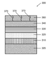
- a pseudomorphic UV light emitting diode (“PUVLED”) structure 300 is formed.
- a semiconductor substrate 305 which includes or consists essentially of one or more semiconductor materials, is provided.
- semiconductor substrate 305 includes or consists essentially of a III-nitride semiconductor material, e.g., AlN.
- Semiconductor substrate 305 may be miscut such that the angle between its c-axis and its surface normal is between approximately 0.3° and approximately 4°. In a preferred embodiment, the misorientation of the surface of semiconductor substrate 305 is approximately 1°.
- the surface of semiconductor substrate 305 may have a group-III (e.g., Al-) polarity or N-polarity, and may be planarized, e.g., by chemical-mechanical polishing.
- the surface of semiconductor substrate 305 is prepared as disclosed in the '838 patent.
- the RMS surface roughness of semiconductor substrate is preferably less than approximately 0.5 nm for a 10 ⁇ m ⁇ 10 ⁇ m area.
- atomic-level steps are detectable on the surface when probed with an atomic-force microscope.
- the threading dislocation density of semiconductor substrate 305 may be measured using, e.g., etch pit density measurements after a 5 minute KOH—NaOH eutectic etch at 450° C.
- the threading dislocation density is less than approximately 2 ⁇ 10 3 cm ⁇ 2 .
- substrate 305 has an even lower threading dislocation density, as described above in reference to semiconductor substrate 200 .
- Semiconductor substrate 305 may be topped with a homoepitaxial layer (not shown) that includes or consists essentially of the same semiconductor material present in semiconductor substrate 300 , e.g., AlN.
- an optional graded buffer layer 310 is formed on semiconductor substrate 305 .
- Graded buffer layer 310 may include or consist essentially of one or more semiconductor materials, e.g., Al x Ga 1-x N.
- graded buffer layer 310 has a composition approximately equal to that of semiconductor substrate 305 at an interface therewith in order to promote two-dimensional growth and avoid deleterious islanding (such islanding may result in undesired elastic strain relief in graded buffer layer 310 and subsequently grown layers).
- graded buffer layer 310 at an interface with subsequently grown layers is generally chosen to be close to (e.g., approximately equal to) that of the desired active region of the device (e.g., the Al x Ga 1-x N concentration that will result in the desired wavelength emission from the PUVLED).
- graded buffer layer 310 includes Al x Ga 1-x N graded from an Al concentration x of approximately 100% to an Al concentration x of approximately 60%.
- a bottom contact layer 320 is subsequently formed above substrate 305 and optional graded layer 310 , and may include or consist essentially of Al x Ga 1-x N doped with at least one impurity, e.g., Si.
- the Al concentration x in bottom contact layer 320 is approximately equal to the final Al concentration x in graded layer 310 (i.e., approximately equal to that of the desired active region (described below) of the device).
- Bottom contact layer 320 may have a thickness sufficient to prevent current crowding after device fabrication (as described below) and/or to stop on during etching to fabricate contacts.
- the thickness of bottom contact layer 320 may be less than approximately 200 nm.
- bottom contact layer 320 When utilizing a bottom contact layer 320 of such thickness, the final PUVLED may be fabricated with back-side contacts, as described below in reference to FIG. 4B .
- bottom contact layer 320 will have high electrical conductivity even with a small thickness due to the low defect density maintained when the layer is pseudomorphic.
- a multiple-quantum well (“MQW”) layer 330 is fabricated above bottom contact layer 320 .
- MQW layer 330 corresponds to the “active region” of PUVLED structure 300 and includes a plurality of quantum wells, each of which may include or consist essentially of AlGaN.
- each period of MQW layer 330 includes an Al x Ga 1-x N quantum well and an Al y Ga 1-y N quantum well, where x is different from y.
- the difference between x and y is large enough to obtain good confinement of the electrons and holes in the active region, thus enabling high ratio of radiative recombination to non-radiative recombination.
- the difference between x and y is approximately 0.05, e.g., x is approximately 0.35 and y is approximately 0.4. However, if the difference between x and y is too large, e.g., greater than approximately 0.3, deleterious islanding may occur during formation of MQW layer 330 .
- MQW layer 330 may include a plurality of such periods, and may have a total thickness less than approximately 50 nm.
- MQW layer 330 may be formed an optional thin electron-blocking (or hole-blocking if the n-type contact is put on top of the device) layer 340 , which includes or consists essentially of, e.g., Al x Ga 1-x N, which may be doped with one or more impurities such as Mg.
- Electron-blocking layer 340 has a thickness that may range between, e.g., approximately 10 nm and approximately 50 nm.
- a top contact layer 350 is formed above electron blocking layer 340 , and includes or consists essentially of one or more semiconductor materials, e.g., Al x Ga 1-x N, doped with at least one impurity such as Mg.
- Top contact layer 350 is doped either n-type or p-type, but with conductivity opposite that of bottom contact layer 310 .
- the thickness of top contact layer 350 is, e.g., between approximately 50 nm and approximately 100 nm.
- Top contact layer 350 is capped with a cap layer 360 , which includes or consists essentially of one or more semiconductor materials doped with the same conductivity as top contact layer 350 .
- cap layer 360 includes GaN doped with Mg, and has a thickness between approximately 10 nm and approximately 200 nm, preferably approximately 50 nm.
- high-quality ohmic contacts may be made directly to top contact layer 350 and cap layer 360 is omitted.
- top contact layer 350 and/or electron-blocking layer 340 are omitted and the top contact is formed directly on cap layer 360 (in such embodiments, cap layer 360 may be considered to be a “top contact layer”). While it is preferred that layers 310 - 340 are all pseudomorphic, top contact layer 350 and/or cap layer 360 may relax without introducing deleterious defects into the active layers below which would adversely affect the performance of PUVLED structure 300 (as described below with reference to FIGS. 3B and 3C ). As described below with reference to FIGS. 4A and 4B , etching and final contact formation completes the formation of PUVLED structure 300 .
- Each of layers 310 - 350 is pseudomorphic, and each layer individually may have a thickness greater than its predicted critical thickness, as described above. Moreover, the collective layer structure including layers 310 - 350 may have a total thickness greater than the predicted critical thickness for the layers considered collectively (i.e., for a multiple-layer structure, the entire structure has a predicted critical thickness even when each individual layer would be less than a predicted critical thickness thereof considered in isolation).
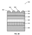
- layers 310 - 340 of PUVLED structure 300 are pseudomorphic, and cap layer 360 is intentionally relaxed. As shown in FIGS. 3B and 3C , layers 310 - 340 are formed as described above with reference to FIG. 3A . Cap layer 360 is subsequently formed in a substantially strain-relaxed state via judicious selection of its composition and/or the deposition conditions. For example, the lattice mismatch between cap layer 360 and substrate 305 and/or MQW layer 330 may be greater than approximately 1%, greater than approximately 2%, or even greater than approximately 3%.
- cap layer 360 includes or consists essentially of undoped or doped GaN
- substrate 305 includes or consists essentially of AlN
- MQW layer 330 includes or consists essentially of multiple Al 0.55 Ga 0.45 N quantum wells interleaved with Al 0.7 Ga 0.3 N barrier layers
- cap layer 360 is lattice mismatched by approximately 2.4%.
- Cap layer 360 may be substantially relaxed, i.e., may have a lattice parameter approximately equal to its theoretical unstrained lattice constant.
- a graded layer may be formed between layers 310 - 340 and cap layer 360 , and its composition at its interfaces with layers 340 , 360 may substantially match the compositions of those layers.
- the thickness of this graded layer may range between approximately 10 nm and approximately 50 nm, e.g., approximately 30 nm.
- epitaxial growth may be temporarily stopped between growth of the graded layer and cap layer 360 .
- an electron-blocking layer 340 including or consisting essentially of Al 0.8 Ga 0.2 N is formed over MQW layer 330 .
- a graded layer is formed over electron-blocking layer 340 .
- the graded layer is graded in composition from Al 0.8 Ga 0.2 N to GaN over a thickness of approximately 30 nm.
- the graded layer may be formed by, e.g., MOCVD, and in this embodiment is formed by ramping the flow of TMA and TMG (by ramping the flow of hydrogen through their respective bubblers) from the conditions utilized to form electron-blocking layer 340 to 0 standard cubic centimeters per minute (sccm) and 6.4 sccm, respectively, over a period of approximately 24 minutes, thus resulting in a monotonic grade from Al 0.8 Ga 0.2 N to GaN (all of the other growth conditions are substantially fixed).
- the thickness of the graded layer in this exemplary embodiment is approximately 30 nm.
- the TMG flow is cut off and epitaxial growth is stopped.
- the growth interruption may allow the surface of the epitaxial graded Al x Ga 1-x N layer to equilibrate, thus enhancing island formation in cap layer 360 once growth is reinitiated.
- the growth interruption may last between approximately 15 seconds and approximately 5 minutes, e.g., approximately 1 minute.
- the ammonia flow is increased from approximately 2 l/min to approximately 81/min, the temperature is decreased by approximately 40° C. (e.g., from a growth temperature of approximately 1100° C. for electron-blocking layer 340 to approximately 1060° C.), and the chamber pressure is increased from approximately 20 Ton to approximately 100 Ton.
- the doping concentration may also be adjusted during the growth interruption.
- supply of Mg dopant is increased by increasing hydrogen flow through the Mg-source bubbler from approximately 350 sccm to approximately 500 sccm.
- cap layer 360 is grown to a thickness of approximately 200 nm at a rate of approximately 1.5 ⁇ m/hr.
- the TMG flow i.e., the hydrogen flow through the TMG source
- the V/III ratio is approximately 1200.
- Cap layer 360 typically forms as a series of islands that coalesce upon further growth, as described below.
- cap layer 360 may be initially formed as a group of islands (e.g., via a Stranski-Krastanov or Volmer-Weber growth mode) that are substantially relaxed.
- an islanded cap layer 360 e.g., a cap layer including or consisting essentially of uncoalesced islands
- further growth of cap layer 360 results in coalescence of islands into a unified cap layer 360 containing a plurality of defects 370 .
- the defects 370 may include misfit dislocations formed at the bottom interface of cap layer 360 that serve to relax cap layer 360 and also may serve to block propagation of other defects into underlying strained layer(s).
- the array of misfit dislocations may not be an array of screw dislocations characteristic of a twist boundary between wafer-bonded layers.
- Defects 370 may also include threading dislocations that propagate from the misfit dislocation network through the thickness of cap layer 360 . It should be emphasized the defects 370 are only formed in cap layer 360 (and possibly any layers formed thereover), but do not reach underlying layers such as MQW layer 330 . Since in most embodiments cap layer 360 merely serves as an electrical contact layer in a subsequently formed device (as detailed below), predominantly only majority carriers are supplied therefrom, a process substantially unaffected by the presence of defects 370 .
- the defect density (e.g., the threading dislocation density) in cap layer 360 is greater than that in MQW layer 330 and/or substrate 305 by at least two orders of magnitude, at least three orders of magnitude, or even at least five orders of magnitude.
- increased V/III ratio, decreased growth temperature, and/or increased chamber pressure (e.g., compared to growth conditions for underlying layers) facilitate the growth of cap layer 360 as a series of islands.
- cap layer 360 may enable the utilization of top contact layers more easily doped (and to higher levels) than layers more closely lattice matched to MQW 330 and/or substrate 305 .
- p-type doping of AlN layers and Al x Ga 1-x N layers with large Al concentration x, e.g., x greater than approximately 50%
- GaN layers and Al x Ga 1-x N layers with low Al concentration x
- a cap layer 360 including or consisting essentially of GaN may be p-type doped such that it has a hole concentration at room temperature ranging between approximately 1 ⁇ 10 17 /cm 3 and approximately 1 ⁇ 10 20 /cm 3
- a cap layer 360 including or consisting essentially of AlN may be p-type doped such that it has a hole concentration at room temperature of less than approximately 1 ⁇ 10 12 /cm 3
- the hole concentrations of such doped layers may be less than the physical concentration of dopants, as dopants may not be electrically active in some layers.
- cap layer 360 is intentionally relaxed, the strain energy is shared by fewer layers, relaxing thickness constraints for each of layers 310 - 340 .
- PUVLED structure 300 (and/or strained epitaxial layer 220 described above) are formed substantially free (i.e., having less than approximately 1 mm ⁇ 2 , or even approximately 0 mm ⁇ 2 ) of macroscopic defects such as pinholes, mounds, or “V pits.” Such defects are often observed in the growth of, e.g., strained InGaN layers on GaN substrates with high dislocation densities. (See T. L. Song, J. Appl. Phys. 98, 084906 (2005), the entire content of which is hereby incorporated by reference).
- Macroscopic defects may cause local relaxation of the strain in the pseudomorphic layer(s), deleteriously affect devices fabricated from the epitaxial layers due to disruptions of the quantum well structures and/or shorting of the p- and n-type contacts, or increase the surface roughness of the layers.
- Macroscopic defect-free PUVLED structure 300 may advantageously be utilized in the fabrication of PUVLEDs sized greater than approximately 0.1 mm ⁇ approximately 0.1 mm.
- PUVLED structure 300 has an emission wavelength in the range of approximately 210 nm to approximately 320 nm, e.g., approximately 280 nm.
- the threading dislocation density in the layers is less than approximately 10 5 cm ⁇ 2 , and may be approximately equal to the threading dislocation density in substrate 305 .
- the threading dislocation of most layers may be approximately equal to that of the substrate and significantly higher in intentionally relaxed cap layers.
- PUVLED structure 300 has a wall-plug efficiency (i.e., total optical power out divided by total electrical power in) greater than approximately 10% (or even greater than approximately 20% in some embodiments) and/or a lifetime greater than approximately 10,000 hours.
- Laser diode (LD) structures may also benefit from a pseudomorphic structure.
- a preferred LD structure will be similar to that of PUVLED structure 300 , with the addition of layers which properly confine photons to create a resonant cavity.
- the resonant cavity will be directed perpendicular to the growth direction and mirrors will be created by cleaving or etching the semiconductor layer structure.
- layer 320 below the MQW layer 330 and layers 340 and 350 above the MQW will need to be modified to act as effective cladding layers to ensure that the emitted photons effectively propagate perpendicular to layer growth direction without significant absorption.
- a vertical cavity surface-emitting laser VCSEL
- layers 320 , 340 , and 350 may be replaced with multilayer structures that will act as mirrors (e.g., Bragg reflectors) to create a photon cavity that will direct photons along the growth direction of the semiconductor layers.
- a semiconductor LD fabricated with nitride semiconductors may have an emission wavelength shorter than approximately 300 nm, and, in some embodiments, shorter than approximately 280 nm.
- PUVLED 400 is formed by etching, e.g., plasma etching, through the layer sequence in PUVLED structure 300 and stopping on or in bottom contact layer 310 .
- Contacts 410 , 420 are formed on bottom contact layer 310 and on cap layer 360 , respectively.
- Contacts 410 , 420 are formed of a conductive material, e.g., a metal such as Ni/Au alloy (typically used for p-type contacts) or a Ti/Al/Ti/Au stack (typically used for n-type contacts), and may be formed by, e.g., sputtering or evaporation.
- Contacts 410 , 420 may include or consist essentially of the same or different conductive materials (such that optimal contact is made to the oppositely doped bottom contact layer 310 and cap layer 360 ).
- Contact 420 may also include an ultraviolet (“UV”) reflector.
- the UV reflector is designed to improve the extraction efficiency of photons created in the active region of the device by redirecting photons which are emitted toward contact 420 (where they cannot escape from the semiconductor layer structure) and redirecting them toward a desired emission surface, e.g., the bottom surface of PUVLEDs 400 , 450 .
- contact 420 is also formed above cap layer 360 .
- contact 410 (which may be a plurality of separate contacts), is formed on the backside of the PUVLED active layer structure.
- substrate 305 is optionally thinned to approximately 150 ⁇ m by, e.g., mechanical grinding or polishing. In other embodiments, the substrate 305 is thinned to approximately 20 ⁇ m or even completely removed.
- a mask layer (not shown), formed of, e.g., Ni, is formed on the backside of substrate 305 and patterned by standard photolithography. The exposed regions of substrate 305 are etched by, e.g., plasma or wet etching, and the etch is stopped on or in bottom contact layer 310 .
- Etch stopping on bottom contact layer 310 is facilitated by detection of Ga in the plasma etcher as substrate 305 will be pure AlN in many embodiments.
- Contact 410 is then formed on the exposed portions of bottom contact layer 310 .
- Contact 410 may be interdigitated to maximize the light output from PUVLED 450 .
- the tapered structures created on the backside of substrate 305 will help gather photons from a much larger emission angle from the MQW structure in layer 340 and direct them out the emission surface near the tips of the taped features shown on the etched backside of the substrate 305 shown in FIG. 4B .
- the photon extraction of PUVLED 400 depicted in FIG. 4A may also be enhanced by patterning the backside of substrate 305 , as shown in FIG. 4C .
- the backside of substrate 305 may be patterned by exposure to a wet chemical etchant.
- substrate 305 is thinned before being patterned. The thinning steps may be omitted in some cases, depending on the absorption coefficient of the substrate 305 and its initial thickness. Photon extraction from PUVLED 400 may be inhibited because photons that reach the outer wall of the substrate 305 have a finite probability of being reflected back inside and then being absorbed.
- preferred embodiments of the invention feature patterning the back surface of substrate 305 so that most photons that reach it do so at an angle that is within the corresponding escape cone.
- the escape cone angle is approximately 25°.
- photons that reach the wall with a trajectory angle smaller than approximately 25°, depending on their wavelengths, will most likely exit the device without being reflected back at the surface.
- a pattern of substantially conical features (“cones”) with an apex angle of approximately 26° are formed on the back surface of substrate 305 , thus improving photon extraction.
- the back surface may be ground, for example, with a 600 to 1800 grit wheel.
- the removal rate of this step may be purposefully maintained at a low level (approximately 0.3-0.4 ⁇ m/s) in order to avoid damaging the substrate 305 or the device structure 400 .
- the back surface may be polished with a polishing slurry, e.g., a solution of equal parts of distilled water and a commercial colloidal suspension of silica in a buffered solution of KOH and water.
- the removal rate of this step may vary between approximately 10 ⁇ m/min and approximately 15 ⁇ m/min.
- Substrate 305 may be thinned down to a thickness of approximately 200 ⁇ m to approximately 250 ⁇ m, although the scope of the invention is not limited by this range.
- the thinning step is preferably followed by wafer cleaning in, e.g., one or more organic solvents.
- the cleaning step includes immersion of substrate 305 in boiling acetone for approximately 10 minutes, followed by immersion in boiling methanol for approximately 10 minutes.
- the backside thereof is patterned by etching in a suitable solution (e.g., a basic solution such as KOH in deionized (DI) water).
- a suitable solution e.g., a basic solution such as KOH in deionized (DI) water.
- the etching agent is a solution of NaOH in DI water.
- the molarity of the basic solution may vary between approximately 1M and approximately 20M, and the etching time may vary between approximately 1 minute and approximately 60 minutes.
- the temperature of the etching solution may vary between approximately room temperature up to approximately 100° C. Similar results may be obtained when using a higher molarity solution for shorter periods of time and vice versa.
- substrate 305 is etched in a 4M solution of KOH and DI water for 8 minutes while maintaining the solution at approximately 20° C.
- the patterned “cones” begin developing on the back surface of substrate 305 that was not polished with a polishing slurry when etched in a molten 20M K
- Table 1 shows the percentage increase in the output power delivered by PUVLED 400 after the back surface of substrate 305 was etched at room temperature with solutions of different concentrations of KOH.
- the output power of PUVLED 400 fabricated on an AlN substrate 305 increased by up to 78% after the N-surface of the substrate was etched in a 4M solution of KOH and DI water for approximately 8 minutes while maintaining the solution at approximately 20° C.
- the etched surface of substrate 305 may also improve the directionality of the light that is emitted by PUVLED 400 .
- the photons in the escape cone emitted through a smooth semiconductor will be refracted and distributed relatively uniformly throughout the half sphere corresponding to the area above the surface of the semiconductor.
- the number of photons emitted at large angles (from the surface normal) is slightly lower due to the higher probability of reflection at the interface, and drops to approximately 50% of the peak intensity at an angle of approximately 84° from the surface normal in many embodiments featuring unpatterned substrates 305 .
- the light is much more focused towards the surface normal, with the intensity falling to approximately 50% of the peak intensity at an angle of only approximately 30° from the surface normal in many embodiments, thus enabling much higher power densities.
- a device structure including an Al 0.7 Ga 0.3 N:Si layer, a five-period MQW layer consisting of n—Al 0.7 Ga 0.3 N barriers and Al 0.55 Ga 0.45 N wells, a Al 0.8 Ga 0.2 N electron blocking layer (EBL), and a p—GaN contact layer was grown on a c-plane AlN substrate using conventional MOCVD.
- UVLEDs were fabricated using standard LED processing techniques.
- a circular mesa with a 360 ⁇ m diameter was defined by inductively coupled plasma (ICP) etching.
- ICP inductively coupled plasma
- the substrate was thinned to a thickness of approximately 200 ⁇ m, and the backside was roughened for improved light extraction (as detailed above).
- Light output was measured on-wafer through the partially absorbing AlN substrate using a calibrated spectrometer and fiber optic probe.
- Pulsed operation of a PUVLED emitting at 248 nm gave a peak external quantum efficiency (EQE) of 1.44% with an output power of 1.44 mW and a peak power of 16.3 mW with an EQE of 1.09%.
- EQE peak external quantum efficiency
- a 243 nm device reached a peak EQE of 0.73% and an output power of 1 mW at 25 mA, even with some self-heating.
- the same device was able to achieve 14.6 mW and an EQE of 0.72% at 400 mA when operated at low duty cycles in pulsed mode.
Abstract
Description
| Time (min) | 0.1 M | 1 M | 4 M | ||
| 1 | 12% | 20% | 22% | ||
| 2 | 31% | 24% | |||
| 4 | 29% | 18% | |||
| 10 | 20% | ||||
| 30 | 23% | 35% | 31% | ||
Claims (20)
Priority Applications (3)
| Application Number | Priority Date | Filing Date | Title |
|---|---|---|---|
| US12/764,584 US8080833B2 (en) | 2007-01-26 | 2010-04-21 | Thick pseudomorphic nitride epitaxial layers |
| US13/298,570 US10446391B2 (en) | 2007-01-26 | 2011-11-17 | Thick pseudomorphic nitride epitaxial layers |
| US16/558,638 US20200058491A1 (en) | 2007-01-26 | 2019-09-03 | Thick pseudomorphic nitride epitaxial layers |
Applications Claiming Priority (4)
| Application Number | Priority Date | Filing Date | Title |
|---|---|---|---|
| US89757207P | 2007-01-26 | 2007-01-26 | |
| US12/020,006 US9437430B2 (en) | 2007-01-26 | 2008-01-25 | Thick pseudomorphic nitride epitaxial layers |
| US25240809P | 2009-10-16 | 2009-10-16 | |
| US12/764,584 US8080833B2 (en) | 2007-01-26 | 2010-04-21 | Thick pseudomorphic nitride epitaxial layers |
Related Parent Applications (1)
| Application Number | Title | Priority Date | Filing Date |
|---|---|---|---|
| US12/020,006 Continuation-In-Part US9437430B2 (en) | 2007-01-26 | 2008-01-25 | Thick pseudomorphic nitride epitaxial layers |
Related Child Applications (1)
| Application Number | Title | Priority Date | Filing Date |
|---|---|---|---|
| US13/298,570 Continuation US10446391B2 (en) | 2007-01-26 | 2011-11-17 | Thick pseudomorphic nitride epitaxial layers |
Publications (2)
| Publication Number | Publication Date |
|---|---|
| US20100264460A1 US20100264460A1 (en) | 2010-10-21 |
| US8080833B2 true US8080833B2 (en) | 2011-12-20 |
Family
ID=42980351
Family Applications (3)
| Application Number | Title | Priority Date | Filing Date |
|---|---|---|---|
| US12/764,584 Active US8080833B2 (en) | 2007-01-26 | 2010-04-21 | Thick pseudomorphic nitride epitaxial layers |
| US13/298,570 Active 2029-08-24 US10446391B2 (en) | 2007-01-26 | 2011-11-17 | Thick pseudomorphic nitride epitaxial layers |
| US16/558,638 Abandoned US20200058491A1 (en) | 2007-01-26 | 2019-09-03 | Thick pseudomorphic nitride epitaxial layers |
Family Applications After (2)
| Application Number | Title | Priority Date | Filing Date |
|---|---|---|---|
| US13/298,570 Active 2029-08-24 US10446391B2 (en) | 2007-01-26 | 2011-11-17 | Thick pseudomorphic nitride epitaxial layers |
| US16/558,638 Abandoned US20200058491A1 (en) | 2007-01-26 | 2019-09-03 | Thick pseudomorphic nitride epitaxial layers |
Country Status (1)
| Country | Link |
|---|---|
| US (3) | US8080833B2 (en) |
Cited By (28)
| Publication number | Priority date | Publication date | Assignee | Title |
|---|---|---|---|---|
| US20090250626A1 (en) * | 2008-04-04 | 2009-10-08 | Hexatech, Inc. | Liquid sanitization device |
| US20120015513A1 (en) * | 2010-07-14 | 2012-01-19 | Sumitomo Electric Device Innovations, Inc. | Method for fabricating semiconductor device |
| US8222650B2 (en) | 2001-12-24 | 2012-07-17 | Crystal Is, Inc. | Nitride semiconductor heterostructures and related methods |
| US8323406B2 (en) | 2007-01-17 | 2012-12-04 | Crystal Is, Inc. | Defect reduction in seeded aluminum nitride crystal growth |
| US20120313077A1 (en) * | 2011-06-10 | 2012-12-13 | The Regents Of The University Of California | High emission power and low efficiency droop semipolar blue light emitting diodes |
| US20140113424A1 (en) * | 2010-12-03 | 2014-04-24 | Taiwan Semiconductor Manufacturing Company, Ltd. | Source/Drain Stressor Having Enhanced Carrier Mobility and Method for Manufacturing Same |
| US8747552B2 (en) | 2005-12-02 | 2014-06-10 | Crystal Is, Inc. | Doped aluminum nitride crystals and methods of making them |
| WO2014120637A1 (en) | 2013-01-29 | 2014-08-07 | Hexatech, Inc. | Optoelectronic devices incorporating single crystalline aluminum nitride substrate |
| US20140264263A1 (en) * | 2013-03-15 | 2014-09-18 | James R. Grandusky | Pseudomorphic electronic and optoelectronic devices having planar contacts |
| US20150108494A1 (en) * | 2013-10-22 | 2015-04-23 | Epistar Corporation | Light-emitting device and manufacturing method thereof |
| US9028612B2 (en) | 2010-06-30 | 2015-05-12 | Crystal Is, Inc. | Growth of large aluminum nitride single crystals with thermal-gradient control |
| US9034103B2 (en) | 2006-03-30 | 2015-05-19 | Crystal Is, Inc. | Aluminum nitride bulk crystals having high transparency to ultraviolet light and methods of forming them |
| WO2015157178A1 (en) | 2014-04-07 | 2015-10-15 | Crystal Is, Inc. | Ultraviolet light-emitting devices and methods |
| US20160005919A1 (en) * | 2013-02-05 | 2016-01-07 | Tokuyama Corporation | Nitride semiconductor light emitting device |
| US9312428B2 (en) | 2013-01-09 | 2016-04-12 | Sensor Electronic Technology, Inc. | Light emitting heterostructure with partially relaxed semiconductor layer |
| US9447521B2 (en) | 2001-12-24 | 2016-09-20 | Crystal Is, Inc. | Method and apparatus for producing large, single-crystals of aluminum nitride |
| US9680057B2 (en) | 2015-09-17 | 2017-06-13 | Crystal Is, Inc. | Ultraviolet light-emitting devices incorporating two-dimensional hole gases |
| US9748409B2 (en) | 2013-03-14 | 2017-08-29 | Hexatech, Inc. | Power semiconductor devices incorporating single crystalline aluminum nitride substrate |
| US9771666B2 (en) | 2007-01-17 | 2017-09-26 | Crystal Is, Inc. | Defect reduction in seeded aluminum nitride crystal growth |
| US9840790B2 (en) | 2012-08-23 | 2017-12-12 | Hexatech, Inc. | Highly transparent aluminum nitride single crystalline layers and devices made therefrom |
| US9960315B2 (en) | 2013-01-09 | 2018-05-01 | Sensor Electronic Technology, Inc. | Light emitting heterostructure with partially relaxed semiconductor layer |
| US9960262B2 (en) | 2016-02-25 | 2018-05-01 | Raytheon Company | Group III—nitride double-heterojunction field effect transistor |
| US10074784B2 (en) | 2011-07-19 | 2018-09-11 | Crystal Is, Inc. | Photon extraction from nitride ultraviolet light-emitting devices |
| US10224458B2 (en) | 2015-03-06 | 2019-03-05 | Stanley Electric Co., Ltd. | Group III nitride laminate, luminescence element comprising said laminate, and method of producing group III nitride laminate |
| US10446391B2 (en) | 2007-01-26 | 2019-10-15 | Crystal Is, Inc. | Thick pseudomorphic nitride epitaxial layers |
| DE112018005414T5 (en) | 2017-11-10 | 2020-07-09 | Crystal Is, Inc. | Large, UV-transparent aluminum nitride single crystals and process for their production |
| TWI730494B (en) * | 2019-11-06 | 2021-06-11 | 錼創顯示科技股份有限公司 | Semiconductor structure |
| DE112020003863T5 (en) | 2019-08-15 | 2022-05-19 | Crystal Is, Inc. | DIAMETER EXPANSION OF ALUMINUM NITRIDE CRYSTALS |
Families Citing this family (24)
| Publication number | Priority date | Publication date | Assignee | Title |
|---|---|---|---|---|
| US20060005763A1 (en) | 2001-12-24 | 2006-01-12 | Crystal Is, Inc. | Method and apparatus for producing large, single-crystals of aluminum nitride |
| JP5283502B2 (en) * | 2005-05-11 | 2013-09-04 | ノース・キャロライナ・ステイト・ユニヴァーシティ | Polarity controlled group III nitride thin film and method for producing the same |
| US8012257B2 (en) | 2006-03-30 | 2011-09-06 | Crystal Is, Inc. | Methods for controllable doping of aluminum nitride bulk crystals |
| CN101652832B (en) | 2007-01-26 | 2011-06-22 | 晶体公司 | Thick pseudomorphic nitride epitaxial layers |
| US8088220B2 (en) | 2007-05-24 | 2012-01-03 | Crystal Is, Inc. | Deep-eutectic melt growth of nitride crystals |
| US7915178B2 (en) | 2008-07-30 | 2011-03-29 | North Carolina State University | Passivation of aluminum nitride substrates |
| US8481991B2 (en) | 2009-08-21 | 2013-07-09 | The Regents Of The University Of California | Anisotropic strain control in semipolar nitride quantum wells by partially or fully relaxed aluminum indium gallium nitride layers with misfit dislocations |
| EP2467872A4 (en) * | 2009-08-21 | 2013-10-09 | Univ California | Semipolar nitride-based devices on partially or fully relaxed alloys with misfit dislocations at the heterointerface |
| EP2633592A1 (en) * | 2010-10-26 | 2013-09-04 | The Regents of the University of California | Limiting strain relaxation in iii-nitride heterostructures by substrate and epitaxial layer patterning |
| EP2634294B1 (en) * | 2010-10-29 | 2020-04-29 | Tokuyama Corporation | Method for manufacturing optical element and optical element multilayer body |
| JP2013128103A (en) * | 2011-11-17 | 2013-06-27 | Sanken Electric Co Ltd | Nitride semiconductor device and nitride semiconductor device manufacturing method |
| US10490697B2 (en) | 2011-12-03 | 2019-11-26 | Sensor Electronic Technology, Inc. | Epitaxy technique for growing semiconductor compounds |
| US10158044B2 (en) | 2011-12-03 | 2018-12-18 | Sensor Electronic Technology, Inc. | Epitaxy technique for growing semiconductor compounds |
| KR101943356B1 (en) * | 2011-12-14 | 2019-01-29 | 엘지전자 주식회사 | Nitride semiconductor using selective growth and method thereof |
| WO2013116622A1 (en) * | 2012-02-01 | 2013-08-08 | Sensor Electronic Technology, Inc. | Epitaxy technique for reducing threading dislocations in stressed semiconductor compounds |
| WO2013175697A1 (en) * | 2012-05-22 | 2013-11-28 | パナソニック株式会社 | Nitride semiconductor light emitting device |
| US20140154826A1 (en) * | 2012-11-30 | 2014-06-05 | Palo Alto Research Center Incorporated | Etch stop layers in nitride semiconductors created by polarity inversion |
| CN104134729B (en) * | 2013-05-03 | 2017-04-26 | 展晶科技(深圳)有限公司 | luminous chip and manufacturing method thereof |
| WO2015157589A1 (en) * | 2014-04-10 | 2015-10-15 | Sensor Electronic Technology, Inc. | Structured substrate |
| US10170549B2 (en) | 2014-10-21 | 2019-01-01 | Samsung Electronics Co., Ltd. | Strained stacked nanosheet FETs and/or quantum well stacked nanosheet |
| US20180076354A1 (en) * | 2015-03-27 | 2018-03-15 | Ohio State Innovation Foundation | Ultraviolet light emitting diodes with tunnel junction |
| TWI562403B (en) * | 2015-11-12 | 2016-12-11 | Playnitride Inc | Semiconductor light-emitting device |
| US11211525B2 (en) | 2017-05-01 | 2021-12-28 | Ohio State Innovation Foundation | Tunnel junction ultraviolet light emitting diodes with enhanced light extraction efficiency |
| US20190267526A1 (en) | 2018-02-26 | 2019-08-29 | Semicon Light Co., Ltd. | Semiconductor Light Emitting Devices And Method Of Manufacturing The Same |
Citations (175)
| Publication number | Priority date | Publication date | Assignee | Title |
|---|---|---|---|---|
| US3531245A (en) | 1968-04-01 | 1970-09-29 | Du Pont | Magnesium-aluminum nitrides |
| US3600701A (en) | 1968-03-14 | 1971-08-17 | Gen Electric | Signal generator for producing a set of signals at baseband frequency and with adjustable phase slope |
| US3603414A (en) | 1970-01-30 | 1971-09-07 | Frank E Stebley | Insert for drilling unit |
| US3607014A (en) | 1968-12-09 | 1971-09-21 | Dow Chemical Co | Method for preparing aluminum nitride and metal fluoride single crystals |
| US3634149A (en) | 1966-10-25 | 1972-01-11 | Philips Corp | Method of manufacturing aluminium nitride crystals for semiconductor devices |
| US3768983A (en) | 1971-11-03 | 1973-10-30 | North American Rockwell | Single crystal beryllium oxide growth from calcium oxide-beryllium oxide melts |
| US3903357A (en) | 1971-12-06 | 1975-09-02 | Westinghouse Electric Corp | Adaptive gate video gray level measurement and tracker |
| US3933573A (en) | 1973-11-27 | 1976-01-20 | The United States Of America As Represented By The Secretary Of The Air Force | Aluminum nitride single crystal growth from a molten mixture with calcium nitride |
| US4008851A (en) | 1976-01-16 | 1977-02-22 | Curt G. Joa, Inc. | Adhesive tape bag closure |
| US4088515A (en) | 1973-04-16 | 1978-05-09 | International Business Machines Corporation | Method of making semiconductor superlattices free of misfit dislocations |
| US4234554A (en) | 1977-11-11 | 1980-11-18 | Max-Planck-Gesellschaft Zur Forderung Der Wissenschaften E.V. | Stable crystalline lithium nitride and process for its preparation |
| US4547471A (en) | 1983-11-18 | 1985-10-15 | General Electric Company | High thermal conductivity aluminum nitride ceramic body |
| US5070393A (en) | 1988-12-23 | 1991-12-03 | Kabushiki Kaisha Toshiba | Aluminum nitride substrate for formation of thin-film conductor layer and semiconductor device using the substrate |
| US5087949A (en) | 1989-06-27 | 1992-02-11 | Hewlett-Packard Company | Light-emitting diode with diagonal faces |
| US5292487A (en) | 1991-04-16 | 1994-03-08 | Sumitomo Electric Industries, Ltd. | Czochralski method using a member for intercepting radiation from raw material molten solution and apparatus therefor |
| US5312698A (en) | 1988-09-13 | 1994-05-17 | Kabushiki Kaisha Toshiba | Aluminum nitride substrate and method for producing same |
| US5494861A (en) | 1993-01-28 | 1996-02-27 | New Japan Radio Co., Ltd. | Method for heat-treating a compound semiconductor |
| US5520785A (en) | 1994-01-04 | 1996-05-28 | Motorola, Inc. | Method for enhancing aluminum nitride |
| US5525320A (en) | 1994-07-11 | 1996-06-11 | University Of Cincinnati | Process for aluminum nitride powder production |
| US5571603A (en) | 1994-02-25 | 1996-11-05 | Sumitomo Electric Industries, Ltd. | Aluminum nitride film substrate and process for producing same |
| US5670798A (en) * | 1995-03-29 | 1997-09-23 | North Carolina State University | Integrated heterostructures of Group III-V nitride semiconductor materials including epitaxial ohmic contact non-nitride buffer layer and methods of fabricating same |
| US5703397A (en) | 1991-11-28 | 1997-12-30 | Tokyo Shibaura Electric Co | Semiconductor package having an aluminum nitride substrate |
| US5728635A (en) | 1995-08-03 | 1998-03-17 | Ngk Insulators, Ltd. | Aluminum nitride sintered bodies |
| US5858086A (en) | 1996-10-17 | 1999-01-12 | Hunter; Charles Eric | Growth of bulk single crystals of aluminum nitride |
| US5858085A (en) | 1994-08-22 | 1999-01-12 | Mitsubishi Materials Corporation | Method for growing a semiconductor single-crystal |
| US5868837A (en) | 1997-01-17 | 1999-02-09 | Cornell Research Foundation, Inc. | Low temperature method of preparing GaN single crystals |
| US5909036A (en) | 1996-06-25 | 1999-06-01 | Sumitomo Electric Industries, Ltd. | Group III-V nitride semiconductor device |
| US5924874A (en) | 1997-01-30 | 1999-07-20 | Ando Electric Co., Ltd. | IC socket |
| US5954874A (en) | 1996-10-17 | 1999-09-21 | Hunter; Charles Eric | Growth of bulk single crystals of aluminum nitride from a melt |
| US5981980A (en) | 1996-04-22 | 1999-11-09 | Sony Corporation | Semiconductor laminating structure |
| US6000174A (en) | 1997-06-12 | 1999-12-14 | Kotobuki Corporation | Retractable stairs-like stand |
| US6001748A (en) | 1996-06-04 | 1999-12-14 | Sumitomo Electric Industries, Ltd. | Single crystal of nitride and process for preparing the same |
| US6006620A (en) | 1997-12-01 | 1999-12-28 | Chrysler Corporation | Automated manual transmission controller |
| EP0979883A1 (en) | 1997-12-25 | 2000-02-16 | Japan Energy Corporation | Process for the preparation of single crystals of compound semiconductors, equipment therefor, and single crystals of compound semiconductors |
| US6045612A (en) | 1998-07-07 | 2000-04-04 | Cree, Inc. | Growth of bulk single crystals of aluminum nitride |
| US6048813A (en) | 1998-10-09 | 2000-04-11 | Cree, Inc. | Simulated diamond gemstones formed of aluminum nitride and aluminum nitride: silicon carbide alloys |
| US6063185A (en) | 1998-10-09 | 2000-05-16 | Cree, Inc. | Production of bulk single crystals of aluminum nitride, silicon carbide and aluminum nitride: silicon carbide alloy |
| US6086672A (en) | 1998-10-09 | 2000-07-11 | Cree, Inc. | Growth of bulk single crystals of aluminum nitride: silicon carbide alloys |
| US6091085A (en) | 1998-02-19 | 2000-07-18 | Agilent Technologies, Inc. | GaN LEDs with improved output coupling efficiency |
| US6187089B1 (en) | 1999-02-05 | 2001-02-13 | Memc Electronic Materials, Inc. | Tungsten doped crucible and method for preparing same |
| US6211089B1 (en) | 1998-09-23 | 2001-04-03 | Lg Electronics Inc. | Method for fabricating GaN substrate |
| US20010000209A1 (en) | 1997-06-03 | 2001-04-12 | Krames Michael R. | Led having angled sides for increased side light extraction |
| US6270569B1 (en) | 1997-06-11 | 2001-08-07 | Hitachi Cable Ltd. | Method of fabricating nitride crystal, mixture, liquid phase growth method, nitride crystal, nitride crystal powders, and vapor phase growth method |
| US20010024871A1 (en) | 1998-04-24 | 2001-09-27 | Fuji Xerox Co. | Semiconductor device and method and apparatus for manufacturing semiconductor device |
| US20010051433A1 (en) | 1999-11-04 | 2001-12-13 | Francis Alicia F. | Use of csoh in a dielectric cmp slurry |
| EP0609799B1 (en) | 1993-02-02 | 2002-05-08 | Texas Instruments Incorporated | Improvements in heteroepitaxy by large surface steps |
| US6398867B1 (en) | 1999-10-06 | 2002-06-04 | General Electric Company | Crystalline gallium nitride and method for forming crystalline gallium nitride |
| US6404125B1 (en) | 1998-10-21 | 2002-06-11 | Sarnoff Corporation | Method and apparatus for performing wavelength-conversion using phosphors with light emitting diodes |
| US6447604B1 (en) | 2000-03-13 | 2002-09-10 | Advanced Technology Materials, Inc. | Method for achieving improved epitaxy quality (surface texture and defect density) on free-standing (aluminum, indium, gallium) nitride ((al,in,ga)n) substrates for opto-electronic and electronic devices |
| US6468347B1 (en) | 1999-09-28 | 2002-10-22 | Sumitomo Electric Industries Ltd. | Method of growing single crystal GaN, method of making single crystal GaN substrate and single crystal GaN substrate |
| US20020170490A1 (en) | 1999-08-04 | 2002-11-21 | The Fox Group, Inc. | Method and apparatus for growing aluminum nitride monocrystals |
| US6515308B1 (en) | 2001-12-21 | 2003-02-04 | Xerox Corporation | Nitride-based VCSEL or light emitting diode with p-n tunnel junction current injection |
| US20030047816A1 (en) | 2001-09-05 | 2003-03-13 | Rensselaer Polytechnic Institute | Passivated nanoparticles, method of fabrication thereof, and devices incorporating nanoparticles |
| US6548405B2 (en) | 1998-11-13 | 2003-04-15 | Micron Technology, Inc. | Batch processing for semiconductor wafers to form aluminum nitride and titanium aluminum nitride |
| US6592663B1 (en) | 1999-06-09 | 2003-07-15 | Ricoh Company Ltd. | Production of a GaN bulk crystal substrate and a semiconductor device formed on a GaN bulk crystal substrate |
| US6596079B1 (en) | 2000-03-13 | 2003-07-22 | Advanced Technology Materials, Inc. | III-V nitride substrate boule and method of making and using the same |
| US20030160254A1 (en) | 2000-01-19 | 2003-08-28 | Henrichs Joseph Reid | FCSEL that frequency doubles its output emissions using sum-frequency generation |
| US20030168003A1 (en) | 2001-12-24 | 2003-09-11 | Schowalter Leo J. | Method and apparatus for producing large, single-crystals of aluminum nitride |
| US20030216011A1 (en) | 1992-11-20 | 2003-11-20 | Nichia Chemical Industries Ltd. | Light-emitting gallium nitride-based compound semiconductor device |
| US6719843B2 (en) | 2001-09-21 | 2004-04-13 | Crystal Is, Inc. | Powder metallurgy tungsten crucible for aluminum nitride crystal growth |
| US20040130002A1 (en) | 2001-02-23 | 2004-07-08 | Nitronex Corporation | Gallium nitride material devices and methods of forming the same |
| US6777717B1 (en) | 2000-09-21 | 2004-08-17 | Gelcore, Llc | LED reflector for improved light extraction |
| US6791119B2 (en) | 2001-02-01 | 2004-09-14 | Cree, Inc. | Light emitting diodes including modifications for light extraction |
| US20040187766A1 (en) | 2003-03-31 | 2004-09-30 | Fabrice Letertre | Method of fabricating monocrystalline crystals |
| US20040206978A1 (en) | 2002-07-19 | 2004-10-21 | Saxler Adam William | Strain compensated semiconductor structures |
| US20040213309A9 (en) | 1999-07-16 | 2004-10-28 | Hiroshi Amano | Nitride semiconductor layer structure and a nitride semiconductor laser incorporating a portion of same |
| US20040224484A1 (en) | 2003-05-07 | 2004-11-11 | Ohalid Fareed | Methods of growing nitride-based film using varying pulses |
| US20040226917A1 (en) | 2003-04-25 | 2004-11-18 | Saint-Gobain Ceramics & Plastics, Inc. | Methods for machining ceramics |
| US20040245535A1 (en) | 2000-10-23 | 2004-12-09 | General Electric Company | Homoepitaxial gallium-nitride-based light emitting device and method for producing |
| US6831302B2 (en) | 2003-04-15 | 2004-12-14 | Luminus Devices, Inc. | Light emitting devices with improved extraction efficiency |
| US6840431B1 (en) | 2000-03-10 | 2005-01-11 | Honeywell International Inc. | Methods of bonding two aluminum-comprising masses to one another |
| WO2005012602A1 (en) | 2003-07-31 | 2005-02-10 | Sicrystal Aktiengesellschaft | Method and device for aln single crystal production with gas-permeable crucible walls |
| US6861729B2 (en) | 2000-06-19 | 2005-03-01 | Nichia Corporation | Nitride semiconductor substrate and method for manufacturing the same, and nitride semiconductor device using nitride semiconductor substrate |
| US20050062392A1 (en) | 2003-07-28 | 2005-03-24 | Tadashi Sakai | Discharge electrode, a discharge lamp and a method for manufacturing the discharge electrode |
| US20050072986A1 (en) | 2001-09-03 | 2005-04-07 | Nec Corporation | Group-III nitride semiconductor device |
| US20050103257A1 (en) | 2003-11-13 | 2005-05-19 | Xueping Xu | Large area, uniformly low dislocation density GaN substrate and process for making the same |
| US20050142391A1 (en) | 2001-07-06 | 2005-06-30 | Technologies And Devices International, Inc. | Method and apparatus for fabricating crack-free Group III nitride semiconductor materials |
| US20050161697A1 (en) | 2001-09-19 | 2005-07-28 | Sumitomo Electric Industries, Ltd. | AlxInyGa1-x-yN mixture crystal substrate, method of growing same and method of producing same |
| US6936357B2 (en) | 2001-07-06 | 2005-08-30 | Technologies And Devices International, Inc. | Bulk GaN and ALGaN single crystals |
| US20050214992A1 (en) | 2002-12-16 | 2005-09-29 | The Regents Of The University Of California | Fabrication of nonpolar indium gallium nitride thin films, heterostructures and devices by metalorganic chemical vapor deposition |
| US20050269577A1 (en) | 2004-06-08 | 2005-12-08 | Matsushita Electric Industrial Co., Ltd. | Surface treatment method and surface treatment device |
| US20050277214A1 (en) | 2004-06-10 | 2005-12-15 | Sumitomo Electric Industries, Ltd. | Nitride single crystal and producing method thereof |
| US20050285141A1 (en) | 2004-06-28 | 2005-12-29 | Piner Edwin L | Gallium nitride materials and methods associated with the same |
| US20060005763A1 (en) | 2001-12-24 | 2006-01-12 | Crystal Is, Inc. | Method and apparatus for producing large, single-crystals of aluminum nitride |
| US6995402B2 (en) | 2003-10-03 | 2006-02-07 | Lumileds Lighting, U.S., Llc | Integrated reflector cup for a light emitting device mount |
| US20060029832A1 (en) | 2001-06-08 | 2006-02-09 | Xueping Xu | High surface quality GaN wafer and method of fabricating same |
| US20060054075A1 (en) | 2002-12-11 | 2006-03-16 | Robert Dwilinski | Substrate for epitaxy and method of preparing the same |
| US7037738B2 (en) * | 2002-01-18 | 2006-05-02 | Kabushiki Kaisha Toshiba | Method of manufacturing a semiconductor light-emitting element |
| US7037838B2 (en) | 2001-11-20 | 2006-05-02 | Rensselaer Polytechnic Institute | Method for polishing a substrate surface |
| US7056383B2 (en) | 2004-02-13 | 2006-06-06 | The Fox Group, Inc. | Tantalum based crucible |
| US7063741B2 (en) | 2002-03-27 | 2006-06-20 | General Electric Company | High pressure high temperature growth of crystalline group III metal nitrides |
| US7087112B1 (en) | 2003-12-02 | 2006-08-08 | Crystal Is, Inc. | Nitride ceramics to mount aluminum nitride seed for sublimation growth |
| WO2006110512A1 (en) | 2005-04-07 | 2006-10-19 | North Carolina State University | Seeded growth process for preparing aluminum nitride single crystals |
| US7125734B2 (en) | 2005-03-09 | 2006-10-24 | Gelcore, Llc | Increased light extraction from a nitride LED |
| US20060244011A1 (en) | 2005-04-29 | 2006-11-02 | Saxler Adam W | Binary group III-nitride based high electron mobility transistors and methods of fabricating same |
| US20060255341A1 (en) | 2005-04-21 | 2006-11-16 | Aonex Technologies, Inc. | Bonded intermediate substrate and method of making same |
| EP1732145A2 (en) | 2005-06-10 | 2006-12-13 | Samsung Electro-Mechanics Co., Ltd. | Method for manufacturing nitride-based semiconductor device |
| US20060288929A1 (en) | 2005-06-10 | 2006-12-28 | Crystal Is, Inc. | Polar surface preparation of nitride substrates |
| US20070018184A1 (en) | 2005-07-20 | 2007-01-25 | Goldeneye, Inc. | Light emitting diodes with high light extraction and high reflectivity |
| US7186580B2 (en) | 2005-01-11 | 2007-03-06 | Semileds Corporation | Light emitting diodes (LEDs) with improved light extraction by roughening |
| US7211831B2 (en) | 2003-04-15 | 2007-05-01 | Luminus Devices, Inc. | Light emitting device with patterned surfaces |
| US7211146B2 (en) | 2001-09-21 | 2007-05-01 | Crystal Is, Inc. | Powder metallurgy crucible for aluminum nitride crystal growth |
| US20070102721A1 (en) | 2005-11-04 | 2007-05-10 | Denbaars Steven P | High light extraction efficiency light emitting diode (LED) |
| US20070101932A1 (en) | 2001-12-24 | 2007-05-10 | Crystal Is, Inc. | Method and apparatus for producing large, single-crystals of aluminum nitride |
| US20070134827A1 (en) | 2005-11-28 | 2007-06-14 | Bondokov Robert T | Large aluminum nitride crystals with reduced defects and methods of making them |
| US20070131160A1 (en) | 2005-12-02 | 2007-06-14 | Slack Glen A | Doped aluminum nitride crystals and methods of making them |
| EP1211715A3 (en) | 2000-11-21 | 2007-07-04 | Ngk Insulators, Ltd. | A method for fabricating a IIIV nitride film |
| US7244520B2 (en) | 2003-08-12 | 2007-07-17 | Nippon Telegraph And Telephone Corporation | Substrate for nitride semiconductor growth |
| US7250637B2 (en) | 2001-08-09 | 2007-07-31 | Matsushita Electric Industrial Co., Ltd. | Card type LED illumination source |
| US7274043B2 (en) | 2003-04-15 | 2007-09-25 | Luminus Devices, Inc. | Light emitting diode systems |
| US7276779B2 (en) | 2003-11-04 | 2007-10-02 | Hitachi Cable, Ltd. | III-V group nitride system semiconductor substrate |
| US20070243653A1 (en) | 2006-03-30 | 2007-10-18 | Crystal Is, Inc. | Methods for controllable doping of aluminum nitride bulk crystals |
| US7288152B2 (en) | 2003-08-29 | 2007-10-30 | Matsushita Electric Industrial Co., Ltd. | Method of manufacturing GaN crystals and GaN crystal substrate, GaN crystals and GaN crystal substrate obtained by the method, and semiconductor device including the same |
| US20080012034A1 (en) | 2006-07-17 | 2008-01-17 | 3M Innovative Properties Company | Led package with converging extractor |
| US20080036038A1 (en) | 2006-03-10 | 2008-02-14 | Hersee Stephen D | PULSED GROWTH OF CATALYST-FREE GROWITH OF GaN NANOWIRES AND APPLICATION IN GROUP III NITRIDE SEMICONDUCTOR BULK MATERIAL |
| US20080054280A1 (en) | 2006-09-06 | 2008-03-06 | Gelcore Llc | Light emitting packages and methods of making same |
| US20080121910A1 (en) | 2006-11-28 | 2008-05-29 | Michael John Bergmann | Semiconductor Devices Having Low Threading Dislocations and Improved Light Extraction and Methods of Making the Same |
| US20080135861A1 (en) | 2006-12-08 | 2008-06-12 | Luminus Devices, Inc. | Spatial localization of light-generating portions in LEDs |
| US20080144688A1 (en) | 2006-09-06 | 2008-06-19 | Palo Alto Research Center Incorporated | Light emitting devices with an electrically active top reflector contact |
| US20080142817A1 (en) | 2005-06-30 | 2008-06-19 | Cree, Inc. | Chip-scale methods for packaging light emitting devices and chip-scale packaged light emitting devices |
| US20080149945A1 (en) | 2003-08-28 | 2008-06-26 | Hideo Nagai | Semiconductor light emitting device, light emitting module, lighting apparatus, display element and manufacturing method of semiconductor light emitting device |
| US20080149960A1 (en) | 2006-12-26 | 2008-06-26 | Nichia Corporation | Light-emitting apparatus and method of producing the same |
| US20080157111A1 (en) | 2003-04-15 | 2008-07-03 | Luminus Devices, Inc. | Light-emitting devices |
| US20080173887A1 (en) | 2005-03-28 | 2008-07-24 | Stanley Electric Co., Ltd. | Self-luminous device |
| US20080182092A1 (en) | 2007-01-17 | 2008-07-31 | Crystal Is, Inc. | Defect reduction in seeded aluminum nitride crystal growth |
| US20080187016A1 (en) | 2007-01-26 | 2008-08-07 | Schowalter Leo J | Thick Pseudomorphic Nitride Epitaxial Layers |
| US20080191225A1 (en) | 2007-02-12 | 2008-08-14 | Medendorp Nicholas W | Methods of forming packaged semiconductor light emitting devices having front contacts by compression molding |
| US7420218B2 (en) | 2004-03-18 | 2008-09-02 | Matsushita Electric Industrial Co., Ltd. | Nitride based LED with a p-type injection region |
| US20080251808A1 (en) | 2002-08-01 | 2008-10-16 | Takeshi Kususe | Semiconductor light-emitting device, method for manufacturing the same, and light-emitting apparatus including the same |
| US7439552B2 (en) | 2005-07-27 | 2008-10-21 | Matsushita Electric Industrial Co., Ltd. | Semiconductor light-emitting device and method for fabricating the same |
| US20080258165A1 (en) | 2007-04-23 | 2008-10-23 | Goldeneye, Inc. | Light emitting diode chip |
| US20090008654A1 (en) | 2004-12-22 | 2009-01-08 | Hideo Nagai | Semiconductor Light Emitting Device, Illumination Module, Illumination Apparatus, Method For Manufacturing Semiconductor Light Emitting Device, and Method For Manufacturing Semiconductor Light Emitting Element |
| US7476910B2 (en) * | 2004-09-10 | 2009-01-13 | Kabushiki Kaisha Toshiba | Semiconductor light emitting device and method for manufacturing the same |
| US20090014742A1 (en) | 2003-04-15 | 2009-01-15 | Luminus Devices, Inc. | Patterned light emitting devices |
| US20090039373A1 (en) | 2007-07-24 | 2009-02-12 | Toyoda Gosei Co., Ltd. | Group III nitride-based compound semiconductor light emitting device |
| US20090050050A1 (en) | 2007-05-24 | 2009-02-26 | Crystal Is, Inc. | Deep-eutectic melt growth of nitride crystals |
| US20090065791A1 (en) | 2007-09-06 | 2009-03-12 | Jui-Kang Yen | White light led with multiple encapsulation layers |
| US20090078957A1 (en) | 2006-02-06 | 2009-03-26 | Showa Denko K.K. | Light emitting device |
| US7518158B2 (en) | 2003-12-09 | 2009-04-14 | Cree, Inc. | Semiconductor light emitting devices and submounts |
| US7524376B2 (en) | 2006-05-04 | 2009-04-28 | Fairfield Crystal Technology, Llc | Method and apparatus for aluminum nitride monocrystal boule growth |
| US20090121250A1 (en) | 2006-11-15 | 2009-05-14 | Denbaars Steven P | High light extraction efficiency light emitting diode (led) using glass packaging |
| US20090121246A1 (en) | 2005-01-24 | 2009-05-14 | Cree, Inc. | LED with current confinement structure and surface roughening |
| US20090141502A1 (en) | 2007-11-30 | 2009-06-04 | The Regents Of The University Of California | Light output enhanced gallium nitride based thin light emitting diode |
| US20090140279A1 (en) | 2007-12-03 | 2009-06-04 | Goldeneye, Inc. | Substrate-free light emitting diode chip |
| US20090155989A1 (en) | 2005-06-06 | 2009-06-18 | Sumitomo Electric Industries, Ltd. | Nitride semiconductor substrate and method of producing same |
| US20090159910A1 (en) | 2007-12-21 | 2009-06-25 | Hung-Cheng Lin | Light emitting diode structure and method for fabricating the same |
| US7554128B2 (en) | 2002-12-27 | 2009-06-30 | Semiconductor Energy Laboratory Co., Ltd. | Light-emitting apparatus |
| US20090166657A1 (en) | 2007-12-28 | 2009-07-02 | Nichia Corporation | Light emitting device |
| US20090173958A1 (en) | 2008-01-04 | 2009-07-09 | Cree, Inc. | Light emitting devices with high efficiency phospor structures |
| EP2099068A1 (en) | 2006-12-28 | 2009-09-09 | Tokuyama Corporation | Process for producing metallized aluminum nitride substrate |
| US20090233394A1 (en) | 2004-07-02 | 2009-09-17 | Cree, Inc. | Led with substrate modifications for enhanced light extraction and method of making same |
| US20090239357A1 (en) | 2005-03-28 | 2009-09-24 | Showa Denko K.K. | AlGaN SUBSTRATE AND PRODUCTION METHOD THEREOF |
| US20090256163A1 (en) | 2008-04-10 | 2009-10-15 | Cree, Inc. | LEDs using single crystalline phosphor and methods of fabricating same |
| US20090261372A1 (en) | 2004-02-19 | 2009-10-22 | Panasonic Corporation | Semiconductor light emitting device and method for fabricating the same |
| US20090267098A1 (en) | 2008-04-24 | 2009-10-29 | Sung Min Choi | Semiconductor light emitting device |
| JP4355920B2 (en) | 2003-12-08 | 2009-11-04 | ソニー株式会社 | Communication card |
| US20090278148A1 (en) | 2005-12-22 | 2009-11-12 | Showa Denko K.K. | Light-emitting diode and method for fabrication thereof |
| US7631986B2 (en) | 2006-10-31 | 2009-12-15 | Koninklijke Philips Electronics, N.V. | Lighting device package |
| US20090315054A1 (en) | 2008-06-24 | 2009-12-24 | Yu-Sik Kim | Light emitting elements, light emitting devices including light emitting elements and methods of manufacturing such light emitting elements and/or devices |
| US7638346B2 (en) | 2001-12-24 | 2009-12-29 | Crystal Is, Inc. | Nitride semiconductor heterostructures and related methods |
| US20090321771A1 (en) | 2008-06-30 | 2009-12-31 | Yasushi Hattori | Semiconductor light-emitting device |
| US20090321758A1 (en) | 2008-06-25 | 2009-12-31 | Wen-Huang Liu | Led with improved external light extraction efficiency |
| US20100006870A1 (en) | 2005-06-22 | 2010-01-14 | Seoul Opto Device Co., Ltd | Light emitting device |
| US20100012956A1 (en) | 2001-07-17 | 2010-01-21 | Yoo Myung Cheol | Diode having high brightness and method thereof |
| US20100025719A1 (en) | 2008-08-01 | 2010-02-04 | Cree, Inc. | Bond pad design for enhancing light extraction from led chips |
| US20100025717A1 (en) | 2003-12-09 | 2010-02-04 | The Regents Of The University Of California | Highly efficient gallium nitride based light emitting diodes via surface roughening |
| US7674699B2 (en) | 2003-10-17 | 2010-03-09 | Hitachi Cable, Ltd. | III group nitride semiconductor substrate, substrate for group III nitride semiconductor device, and fabrication methods thereof |
| US7713844B2 (en) | 2005-09-07 | 2010-05-11 | Sumitomo Electric Industries, Ltd. | Nitride semiconductor substrate, and method for working nitride semiconductor substrate |
| US7755103B2 (en) | 2006-08-03 | 2010-07-13 | Sumitomo Electric Industries, Ltd. | Nitride gallium semiconductor substrate and nitride semiconductor epitaxial substrate |
| US7803733B2 (en) | 2007-03-27 | 2010-09-28 | Ngk Insulators, Ltd. | Aluminum nitride sintered body and semiconductor manufacturing apparatus member |
| US20100264460A1 (en) | 2007-01-26 | 2010-10-21 | Grandusky James R | Thick pseudomorphic nitride epitaxial layers |
| US20100314551A1 (en) | 2009-06-11 | 2010-12-16 | Bettles Timothy J | In-line Fluid Treatment by UV Radiation |
| US20110008621A1 (en) | 2006-03-30 | 2011-01-13 | Schujman Sandra B | Aluminum nitride bulk crystals having high transparency to ultraviolet light and methods of forming them |
| EP1754810B1 (en) | 2004-05-19 | 2011-05-18 | Sumitomo Electric Industries, Ltd. | Method for producing group iii nitride semiconductor crystal |
| DE10248964B4 (en) | 2002-10-14 | 2011-12-01 | Crystal-N Gmbh | Process for sublimation growth of aluminum nitride single crystals |
Family Cites Families (103)
| Publication number | Priority date | Publication date | Assignee | Title |
|---|---|---|---|---|
| US14036A (en) * | 1856-01-01 | Improvement in grain-binders for harvesters | ||
| US51116A (en) * | 1865-11-21 | Improvement in straw-cutters | ||
| JPS61236686A (en) | 1985-04-13 | 1986-10-21 | Tohoku Metal Ind Ltd | Process for growing single crystal |
| JPS63154090A (en) | 1986-12-16 | 1988-06-27 | Victor Co Of Japan Ltd | Controller for brushless motor |
| JPH01192647A (en) | 1988-01-26 | 1989-08-02 | Mutoh Ind Ltd | Device for detecting double feeding of paper of paper feeding device |
| JP2745408B2 (en) | 1988-07-07 | 1998-04-28 | 東芝セラミックス株式会社 | Semiconductor single crystal pulling equipment |
| US5057287A (en) | 1988-11-01 | 1991-10-15 | Sfa, Inc. | Liquid encapsulated zone melting crystal growth method and apparatus |
| JPH03285075A (en) | 1990-03-30 | 1991-12-16 | Nisshin Steel Co Ltd | Production of tungsten crucible |
| JP2989975B2 (en) | 1992-11-30 | 1999-12-13 | 京セラ株式会社 | Method for manufacturing aluminum nitride substrate |
| JPH06335608A (en) | 1993-05-28 | 1994-12-06 | Kawasaki Steel Corp | Separation of solid matter from solid-liquid mixture and its device |
| US5661074A (en) * | 1995-02-03 | 1997-08-26 | Advanced Technology Materials, Inc. | High brightness electroluminescent device emitting in the green to ultraviolet spectrum and method of making the same |
| US5679965A (en) | 1995-03-29 | 1997-10-21 | North Carolina State University | Integrated heterostructures of Group III-V nitride semiconductor materials including epitaxial ohmic contact, non-nitride buffer layer and methods of fabricating same |
| JP3604205B2 (en) | 1995-09-18 | 2004-12-22 | 日亜化学工業株式会社 | Method for growing nitride semiconductor |
| US5889295A (en) * | 1996-02-26 | 1999-03-30 | Kabushiki Kaisha Toshiba | Semiconductor device |
| US6533874B1 (en) | 1996-12-03 | 2003-03-18 | Advanced Technology Materials, Inc. | GaN-based devices using thick (Ga, Al, In)N base layers |
| US6583444B2 (en) | 1997-02-18 | 2003-06-24 | Tessera, Inc. | Semiconductor packages having light-sensitive chips |
| US6218207B1 (en) | 1998-05-29 | 2001-04-17 | Mitsushita Electronics Corporation | Method for growing nitride semiconductor crystals, nitride semiconductor device, and method for fabricating the same |
| JP3439994B2 (en) | 1998-07-07 | 2003-08-25 | 科学技術振興事業団 | Method for synthesizing low-resistance n-type and low-resistance p-type single-crystal AlN thin films |
| US6319742B1 (en) * | 1998-07-29 | 2001-11-20 | Sanyo Electric Co., Ltd. | Method of forming nitride based semiconductor layer |
| JP3850218B2 (en) * | 1998-09-10 | 2006-11-29 | ローム株式会社 | Semiconductor light emitting device and manufacturing method thereof |
| US6423984B1 (en) * | 1998-09-10 | 2002-07-23 | Toyoda Gosei Co., Ltd. | Light-emitting semiconductor device using gallium nitride compound semiconductor |
| JP4712169B2 (en) * | 1999-09-10 | 2011-06-29 | シャープ株式会社 | Nitride-based semiconductor laser device and optical information reproducing apparatus |
| US7064355B2 (en) | 2000-09-12 | 2006-06-20 | Lumileds Lighting U.S., Llc | Light emitting diodes with improved light extraction efficiency |
| JP2002141556A (en) | 2000-09-12 | 2002-05-17 | Lumileds Lighting Us Llc | Light emitting diode with improved light extraction efficiency |
| US6548333B2 (en) | 2000-12-01 | 2003-04-15 | Cree, Inc. | Aluminum gallium nitride/gallium nitride high electron mobility transistors having a gate contact on a gallium nitride based cap segment |
| JP2005167275A (en) | 2000-12-07 | 2005-06-23 | Ngk Insulators Ltd | Semiconductor device |
| JP2002274996A (en) | 2001-01-15 | 2002-09-25 | Ngk Insulators Ltd | Epitaxial ground substrate and epitaxial substrate |
| US6800876B2 (en) * | 2001-01-16 | 2004-10-05 | Cree, Inc. | Group III nitride LED with undoped cladding layer (5000.137) |
| US6940075B2 (en) | 2001-03-15 | 2005-09-06 | Christopher R. Schulz | Ultraviolet-light-based disinfection reactor |
| JP3876649B2 (en) * | 2001-06-05 | 2007-02-07 | ソニー株式会社 | Nitride semiconductor laser and manufacturing method thereof |
| CN2492947Y (en) | 2001-07-18 | 2002-05-22 | 赵汝杰 | Amorphous Al-In-Ga nitride LED unit |
| US7057211B2 (en) | 2001-10-26 | 2006-06-06 | Ammono Sp. Zo.O | Nitride semiconductor laser device and manufacturing method thereof |
| JP4331906B2 (en) | 2001-12-26 | 2009-09-16 | 日本碍子株式会社 | Method for producing group III nitride film |
| TWI278995B (en) * | 2002-01-28 | 2007-04-11 | Nichia Corp | Nitride semiconductor element with a supporting substrate and a method for producing a nitride semiconductor element |
| JP2003282439A (en) * | 2002-03-27 | 2003-10-03 | Seiko Epson Corp | Substrate for device and manufacturing method thereof |
| US7775685B2 (en) | 2003-05-27 | 2010-08-17 | Cree, Inc. | Power surface mount light emitting die package |
| DE10255849B4 (en) | 2002-11-29 | 2006-06-14 | Advanced Micro Devices, Inc., Sunnyvale | Improved drain / source extension structure of a field effect transistor with high permittivity doped sidewall spacers and method of making the same |
| US20070082019A1 (en) | 2003-02-21 | 2007-04-12 | Ciphergen Biosystems Inc. | Photocrosslinked hydrogel surface coatings |
| US6921929B2 (en) | 2003-06-27 | 2005-07-26 | Lockheed Martin Corporation | Light-emitting diode (LED) with amorphous fluoropolymer encapsulant and lens |
| JP2007529105A (en) * | 2003-07-16 | 2007-10-18 | 松下電器産業株式会社 | Semiconductor light emitting device, method of manufacturing the same, lighting device and display device |
| US7009213B2 (en) * | 2003-07-31 | 2006-03-07 | Lumileds Lighting U.S., Llc | Light emitting devices with improved light extraction efficiency |
| JP3841092B2 (en) * | 2003-08-26 | 2006-11-01 | 住友電気工業株式会社 | Light emitting device |
| EP1673815B1 (en) * | 2003-10-14 | 2019-06-05 | Toyoda Gosei Co., Ltd. | Group iii nitride semiconductor element and semiconductor devices incorporating the same |
| US20050194584A1 (en) * | 2003-11-12 | 2005-09-08 | Slater David B.Jr. | LED fabrication via ion implant isolation |
| JP2005191530A (en) * | 2003-12-03 | 2005-07-14 | Sumitomo Electric Ind Ltd | Light emitting device |
| US7087465B2 (en) | 2003-12-15 | 2006-08-08 | Philips Lumileds Lighting Company, Llc | Method of packaging a semiconductor light emitting device |
| US7341628B2 (en) | 2003-12-19 | 2008-03-11 | Melas Andreas A | Method to reduce crystal defects particularly in group III-nitride layers and substrates |
| JP2005210084A (en) | 2003-12-22 | 2005-08-04 | Ngk Insulators Ltd | Epitaxial substrate, semiconductor laminate structure, dislocation reduction method, and substrate for epitaxial formation |
| DE602005011881C5 (en) * | 2004-04-02 | 2016-07-28 | Nichia Corp. | Nitride semiconductor laser device |
| JP4154731B2 (en) * | 2004-04-27 | 2008-09-24 | 信越半導体株式会社 | Light emitting device manufacturing method and light emitting device |
| JP5194334B2 (en) * | 2004-05-18 | 2013-05-08 | 住友電気工業株式会社 | Method for manufacturing group III nitride semiconductor device |
| JP3920315B2 (en) * | 2004-06-14 | 2007-05-30 | 三菱電線工業株式会社 | Nitride semiconductor light emitting device |
| US7161188B2 (en) * | 2004-06-28 | 2007-01-09 | Matsushita Electric Industrial Co., Ltd. | Semiconductor light emitting element, semiconductor light emitting device, and method for fabricating semiconductor light emitting element |
| US7417220B2 (en) * | 2004-09-09 | 2008-08-26 | Toyoda Gosei Co., Ltd. | Solid state device and light-emitting element |
| US7724321B2 (en) * | 2004-09-24 | 2010-05-25 | Epistar Corporation | Liquid crystal display |
| US7462502B2 (en) | 2004-11-12 | 2008-12-09 | Philips Lumileds Lighting Company, Llc | Color control by alteration of wavelength converting element |
| US7326963B2 (en) * | 2004-12-06 | 2008-02-05 | Sensor Electronic Technology, Inc. | Nitride-based light emitting heterostructure |
| JP2006179511A (en) * | 2004-12-20 | 2006-07-06 | Sumitomo Electric Ind Ltd | Light emitting device |
| US7910937B2 (en) * | 2005-02-02 | 2011-03-22 | Agency For Science, Technology And Research | Method and structure for fabricating III-V nitride layers on silicon substrates |
| US20060181695A1 (en) | 2005-02-11 | 2006-08-17 | Sage Burton H Jr | Compensating liquid delivery system and method |
| JP4792802B2 (en) * | 2005-04-26 | 2011-10-12 | 住友電気工業株式会社 | Surface treatment method of group III nitride crystal |
| JP5236148B2 (en) | 2005-05-12 | 2013-07-17 | 日本碍子株式会社 | EPITAXIAL SUBSTRATE, SEMICONDUCTOR DEVICE, METHOD FOR MANUFACTURING EPITAXIAL SUBSTRATE, METHOD FOR MANUFACTURING SEMICONDUCTOR DEVICE, AND METHOD FOR ALIGNING DISLOCATION IN GROUP III NITRIDE CRYSTAL |
| JP5082278B2 (en) * | 2005-05-16 | 2012-11-28 | ソニー株式会社 | Light emitting diode manufacturing method, integrated light emitting diode manufacturing method, and nitride III-V compound semiconductor growth method |
| JP4277826B2 (en) * | 2005-06-23 | 2009-06-10 | 住友電気工業株式会社 | Nitride crystal, nitride crystal substrate, nitride crystal substrate with epi layer, and semiconductor device and method for manufacturing the same |
| US7800124B2 (en) * | 2005-06-30 | 2010-09-21 | Panasonic Electric Works Co., Ltd. | Light-emitting device |
| JP4963807B2 (en) * | 2005-08-04 | 2012-06-27 | 昭和電工株式会社 | Gallium nitride compound semiconductor light emitting device |
| JP4877712B2 (en) * | 2005-08-04 | 2012-02-15 | 国立大学法人東北大学 | Aluminum nitride single crystal multilayer substrate and method of manufacturing aluminum nitride single crystal film |
| WO2007034575A1 (en) | 2005-09-20 | 2007-03-29 | Matsushita Electric Works, Ltd. | Light emitting device |
| US7777217B2 (en) * | 2005-12-12 | 2010-08-17 | Kyma Technologies, Inc. | Inclusion-free uniform semi-insulating group III nitride substrate and methods for making same |
| US20070151905A1 (en) | 2005-12-29 | 2007-07-05 | Metertek Technology Inc. | Water purifier |
| JP2007184411A (en) * | 2006-01-06 | 2007-07-19 | Sony Corp | Light emitting diode and its manufacturing method, integrated light emitting diode and its manufacturing method, light emitting diode backlight, light emitting diode lighting apparatus, light emitting diode display, electronic equipment, and electronic device and its manufacturing method |
| JP5004597B2 (en) * | 2006-03-06 | 2012-08-22 | シャープ株式会社 | Nitride semiconductor light emitting device and method for manufacturing nitride semiconductor light emitting device |
| GB0606604D0 (en) | 2006-04-01 | 2006-05-10 | P W Circuts Ltd | Treatment apparatus |
| EP2023411A1 (en) * | 2006-05-01 | 2009-02-11 | Mitsubishi Chemical Corporation | Integrated semiconductor light-emitting device and its manufacturing method |
| JP2008010835A (en) * | 2006-05-31 | 2008-01-17 | Sumitomo Electric Ind Ltd | Surface treating method of nitride crystal, nitride crystal substrate, nitride crystal substrate with epitaxial layer, semiconductor device, and manufacturing method of nitride crystal substrate with epitaxial layer and semiconductor device |
| US7943952B2 (en) | 2006-07-31 | 2011-05-17 | Cree, Inc. | Method of uniform phosphor chip coating and LED package fabricated using method |
| JP2008056553A (en) * | 2006-08-01 | 2008-03-13 | Ngk Insulators Ltd | Aluminum nitride single crystal |
| US7915626B1 (en) * | 2006-08-15 | 2011-03-29 | Sandia Corporation | Aluminum nitride transitional layer for reducing dislocation density and cracking of AIGan epitaxial films |
| EP2065931A4 (en) * | 2006-08-22 | 2013-02-27 | Mitsubishi Chem Corp | Semiconductor device member, liquid for forming semiconductor device member, method for manufacturing semiconductor device member, and liquid for forming semiconductor device member using the method, phosphor composition, semiconductor light emitting device, illuminating apparatus and image display apparatus |
| US7872272B2 (en) | 2006-09-06 | 2011-01-18 | Palo Alto Research Center Incorporated | Nitride semiconductor ultraviolet LEDs with tunnel junctions and reflective contact |
| US20080054248A1 (en) * | 2006-09-06 | 2008-03-06 | Chua Christopher L | Variable period variable composition supperlattice and devices including same |
| KR101090900B1 (en) * | 2006-10-18 | 2011-12-08 | 니텍 인코포레이티드 | Vertical deep ultraviolet light emitting diodes |
| KR100845856B1 (en) * | 2006-12-21 | 2008-07-14 | 엘지전자 주식회사 | LED package and method of manufacturing the same |
| JP5383974B2 (en) * | 2006-12-27 | 2014-01-08 | 住友電工デバイス・イノベーション株式会社 | Semiconductor substrate and semiconductor device |
| TWI331816B (en) | 2007-04-03 | 2010-10-11 | Advanced Optoelectronic Tech | Semiconductor light-emitting device |
| US20080280426A1 (en) * | 2007-05-09 | 2008-11-13 | Sharp Laboratories Of America, Inc. | Gallium nitride-on-silicon interface |
| US20080296616A1 (en) * | 2007-06-04 | 2008-12-04 | Sharp Laboratories Of America, Inc. | Gallium nitride-on-silicon nanoscale patterned interface |
| US20090065792A1 (en) | 2007-09-07 | 2009-03-12 | 3M Innovative Properties Company | Method of making an led device having a dome lens |
| US7767579B2 (en) | 2007-12-12 | 2010-08-03 | International Business Machines Corporation | Protection of SiGe during etch and clean operations |
| US8878219B2 (en) * | 2008-01-11 | 2014-11-04 | Cree, Inc. | Flip-chip phosphor coating method and devices fabricated utilizing method |
| US7781780B2 (en) | 2008-03-31 | 2010-08-24 | Bridgelux, Inc. | Light emitting diodes with smooth surface for reflective electrode |
| JP5271601B2 (en) | 2008-05-16 | 2013-08-21 | 株式会社ブリヂストン | Single crystal manufacturing apparatus and manufacturing method |
| CN201274297Y (en) | 2008-09-23 | 2009-07-15 | 王海军 | Large power LED encapsulation structure capable of enhancing brightness |
| DE102009034359A1 (en) | 2009-07-17 | 2011-02-17 | Forschungsverbund Berlin E.V. | P-contact and LED for the ultraviolet spectral range |
| JP5317898B2 (en) | 2009-09-10 | 2013-10-16 | 株式会社アルバック | Method for manufacturing light-emitting diode element |
| TWI649895B (en) | 2010-04-30 | 2019-02-01 | 美國波士頓大學信託會 | High-efficiency ultraviolet light-emitting diode with variable structure position |
| CN105951177B (en) | 2010-06-30 | 2018-11-02 | 晶体公司 | Use the growth for the bulk aluminum nitride single crystal that thermal gradient controls |
| EP2595940B1 (en) | 2010-07-20 | 2019-11-13 | Hexatech Inc. | Polycrystalline aluminum nitride boule and method of production of a polycrystalline aluminum nitride material |
| US8748919B2 (en) | 2011-04-28 | 2014-06-10 | Palo Alto Research Center Incorporated | Ultraviolet light emitting device incorporating optically absorbing layers |
| US8860059B2 (en) | 2011-06-20 | 2014-10-14 | Xiamen Sanan Optoelectronics Technology Co., Ltd. | Light emitting devices, systems, and methods of manufacturing |
| US8962359B2 (en) | 2011-07-19 | 2015-02-24 | Crystal Is, Inc. | Photon extraction from nitride ultraviolet light-emitting devices |
| US9252329B2 (en) | 2011-10-04 | 2016-02-02 | Palo Alto Research Center Incorporated | Ultraviolet light emitting devices having compressively strained light emitting layer for enhanced light extraction |
| WO2014151264A1 (en) | 2013-03-15 | 2014-09-25 | Crystal Is, Inc. | Planar contacts to pseudomorphic electronic and optoelectronic devices |
-
2010
- 2010-04-21 US US12/764,584 patent/US8080833B2/en active Active
-
2011
- 2011-11-17 US US13/298,570 patent/US10446391B2/en active Active
-
2019
- 2019-09-03 US US16/558,638 patent/US20200058491A1/en not_active Abandoned
Patent Citations (191)
| Publication number | Priority date | Publication date | Assignee | Title |
|---|---|---|---|---|
| US3634149A (en) | 1966-10-25 | 1972-01-11 | Philips Corp | Method of manufacturing aluminium nitride crystals for semiconductor devices |
| US3600701A (en) | 1968-03-14 | 1971-08-17 | Gen Electric | Signal generator for producing a set of signals at baseband frequency and with adjustable phase slope |
| US3531245A (en) | 1968-04-01 | 1970-09-29 | Du Pont | Magnesium-aluminum nitrides |
| US3607014A (en) | 1968-12-09 | 1971-09-21 | Dow Chemical Co | Method for preparing aluminum nitride and metal fluoride single crystals |
| US3603414A (en) | 1970-01-30 | 1971-09-07 | Frank E Stebley | Insert for drilling unit |
| US3768983A (en) | 1971-11-03 | 1973-10-30 | North American Rockwell | Single crystal beryllium oxide growth from calcium oxide-beryllium oxide melts |
| US3903357A (en) | 1971-12-06 | 1975-09-02 | Westinghouse Electric Corp | Adaptive gate video gray level measurement and tracker |
| US4088515A (en) | 1973-04-16 | 1978-05-09 | International Business Machines Corporation | Method of making semiconductor superlattices free of misfit dislocations |
| US3933573A (en) | 1973-11-27 | 1976-01-20 | The United States Of America As Represented By The Secretary Of The Air Force | Aluminum nitride single crystal growth from a molten mixture with calcium nitride |
| US4008851A (en) | 1976-01-16 | 1977-02-22 | Curt G. Joa, Inc. | Adhesive tape bag closure |
| US4234554A (en) | 1977-11-11 | 1980-11-18 | Max-Planck-Gesellschaft Zur Forderung Der Wissenschaften E.V. | Stable crystalline lithium nitride and process for its preparation |
| US4547471A (en) | 1983-11-18 | 1985-10-15 | General Electric Company | High thermal conductivity aluminum nitride ceramic body |
| US5312698A (en) | 1988-09-13 | 1994-05-17 | Kabushiki Kaisha Toshiba | Aluminum nitride substrate and method for producing same |
| US5070393A (en) | 1988-12-23 | 1991-12-03 | Kabushiki Kaisha Toshiba | Aluminum nitride substrate for formation of thin-film conductor layer and semiconductor device using the substrate |
| US5087949A (en) | 1989-06-27 | 1992-02-11 | Hewlett-Packard Company | Light-emitting diode with diagonal faces |
| US5292487A (en) | 1991-04-16 | 1994-03-08 | Sumitomo Electric Industries, Ltd. | Czochralski method using a member for intercepting radiation from raw material molten solution and apparatus therefor |
| US5703397A (en) | 1991-11-28 | 1997-12-30 | Tokyo Shibaura Electric Co | Semiconductor package having an aluminum nitride substrate |
| US20030216011A1 (en) | 1992-11-20 | 2003-11-20 | Nichia Chemical Industries Ltd. | Light-emitting gallium nitride-based compound semiconductor device |
| US5494861A (en) | 1993-01-28 | 1996-02-27 | New Japan Radio Co., Ltd. | Method for heat-treating a compound semiconductor |
| EP0609799B1 (en) | 1993-02-02 | 2002-05-08 | Texas Instruments Incorporated | Improvements in heteroepitaxy by large surface steps |
| US5520785A (en) | 1994-01-04 | 1996-05-28 | Motorola, Inc. | Method for enhancing aluminum nitride |
| US5571603A (en) | 1994-02-25 | 1996-11-05 | Sumitomo Electric Industries, Ltd. | Aluminum nitride film substrate and process for producing same |
| US5525320A (en) | 1994-07-11 | 1996-06-11 | University Of Cincinnati | Process for aluminum nitride powder production |
| US5858085A (en) | 1994-08-22 | 1999-01-12 | Mitsubishi Materials Corporation | Method for growing a semiconductor single-crystal |
| US5670798A (en) * | 1995-03-29 | 1997-09-23 | North Carolina State University | Integrated heterostructures of Group III-V nitride semiconductor materials including epitaxial ohmic contact non-nitride buffer layer and methods of fabricating same |
| US5728635A (en) | 1995-08-03 | 1998-03-17 | Ngk Insulators, Ltd. | Aluminum nitride sintered bodies |
| US5981980A (en) | 1996-04-22 | 1999-11-09 | Sony Corporation | Semiconductor laminating structure |
| EP0811708B1 (en) | 1996-06-04 | 2006-06-21 | Sumitomo Electric Industries, Ltd. | Single crystal of nitride and process for preparing it |
| US6001748A (en) | 1996-06-04 | 1999-12-14 | Sumitomo Electric Industries, Ltd. | Single crystal of nitride and process for preparing the same |
| US5909036A (en) | 1996-06-25 | 1999-06-01 | Sumitomo Electric Industries, Ltd. | Group III-V nitride semiconductor device |
| US5972109A (en) | 1996-10-17 | 1999-10-26 | Hunter; Charles Eric | Growth of bulk single crystals of aluminum nitride |
| US5954874A (en) | 1996-10-17 | 1999-09-21 | Hunter; Charles Eric | Growth of bulk single crystals of aluminum nitride from a melt |
| US5858086A (en) | 1996-10-17 | 1999-01-12 | Hunter; Charles Eric | Growth of bulk single crystals of aluminum nitride |
| US6066205A (en) | 1996-10-17 | 2000-05-23 | Cree, Inc. | Growth of bulk single crystals of aluminum nitride from a melt |
| US6296956B1 (en) | 1996-10-17 | 2001-10-02 | Cree, Inc. | Bulk single crystals of aluminum nitride |
| US5868837A (en) | 1997-01-17 | 1999-02-09 | Cornell Research Foundation, Inc. | Low temperature method of preparing GaN single crystals |
| US5924874A (en) | 1997-01-30 | 1999-07-20 | Ando Electric Co., Ltd. | IC socket |
| US20010000209A1 (en) | 1997-06-03 | 2001-04-12 | Krames Michael R. | Led having angled sides for increased side light extraction |
| US6270569B1 (en) | 1997-06-11 | 2001-08-07 | Hitachi Cable Ltd. | Method of fabricating nitride crystal, mixture, liquid phase growth method, nitride crystal, nitride crystal powders, and vapor phase growth method |
| US6000174A (en) | 1997-06-12 | 1999-12-14 | Kotobuki Corporation | Retractable stairs-like stand |
| US6006620A (en) | 1997-12-01 | 1999-12-28 | Chrysler Corporation | Automated manual transmission controller |
| EP0979883A1 (en) | 1997-12-25 | 2000-02-16 | Japan Energy Corporation | Process for the preparation of single crystals of compound semiconductors, equipment therefor, and single crystals of compound semiconductors |
| US6091085A (en) | 1998-02-19 | 2000-07-18 | Agilent Technologies, Inc. | GaN LEDs with improved output coupling efficiency |
| US20010024871A1 (en) | 1998-04-24 | 2001-09-27 | Fuji Xerox Co. | Semiconductor device and method and apparatus for manufacturing semiconductor device |
| US6045612A (en) | 1998-07-07 | 2000-04-04 | Cree, Inc. | Growth of bulk single crystals of aluminum nitride |
| US6211089B1 (en) | 1998-09-23 | 2001-04-03 | Lg Electronics Inc. | Method for fabricating GaN substrate |
| US6086672A (en) | 1998-10-09 | 2000-07-11 | Cree, Inc. | Growth of bulk single crystals of aluminum nitride: silicon carbide alloys |
| US6048813A (en) | 1998-10-09 | 2000-04-11 | Cree, Inc. | Simulated diamond gemstones formed of aluminum nitride and aluminum nitride: silicon carbide alloys |
| US6063185A (en) | 1998-10-09 | 2000-05-16 | Cree, Inc. | Production of bulk single crystals of aluminum nitride, silicon carbide and aluminum nitride: silicon carbide alloy |
| US6404125B1 (en) | 1998-10-21 | 2002-06-11 | Sarnoff Corporation | Method and apparatus for performing wavelength-conversion using phosphors with light emitting diodes |
| US6548405B2 (en) | 1998-11-13 | 2003-04-15 | Micron Technology, Inc. | Batch processing for semiconductor wafers to form aluminum nitride and titanium aluminum nitride |
| US6187089B1 (en) | 1999-02-05 | 2001-02-13 | Memc Electronic Materials, Inc. | Tungsten doped crucible and method for preparing same |
| US6592663B1 (en) | 1999-06-09 | 2003-07-15 | Ricoh Company Ltd. | Production of a GaN bulk crystal substrate and a semiconductor device formed on a GaN bulk crystal substrate |
| US20040213309A9 (en) | 1999-07-16 | 2004-10-28 | Hiroshi Amano | Nitride semiconductor layer structure and a nitride semiconductor laser incorporating a portion of same |
| US20020170490A1 (en) | 1999-08-04 | 2002-11-21 | The Fox Group, Inc. | Method and apparatus for growing aluminum nitride monocrystals |
| US6468347B1 (en) | 1999-09-28 | 2002-10-22 | Sumitomo Electric Industries Ltd. | Method of growing single crystal GaN, method of making single crystal GaN substrate and single crystal GaN substrate |
| US6398867B1 (en) | 1999-10-06 | 2002-06-04 | General Electric Company | Crystalline gallium nitride and method for forming crystalline gallium nitride |
| US20010051433A1 (en) | 1999-11-04 | 2001-12-13 | Francis Alicia F. | Use of csoh in a dielectric cmp slurry |
| US20030160254A1 (en) | 2000-01-19 | 2003-08-28 | Henrichs Joseph Reid | FCSEL that frequency doubles its output emissions using sum-frequency generation |
| US6840431B1 (en) | 2000-03-10 | 2005-01-11 | Honeywell International Inc. | Methods of bonding two aluminum-comprising masses to one another |
| US6596079B1 (en) | 2000-03-13 | 2003-07-22 | Advanced Technology Materials, Inc. | III-V nitride substrate boule and method of making and using the same |
| US20030213964A1 (en) | 2000-03-13 | 2003-11-20 | Flynn Jeffrey S. | III-V Nitride homoepitaxial material of improved MOVPE epitaxial quality (surface texture and defect density) formed on free-standing (Al,In,Ga)N substrates, and opto-electronic and electronic devices comprising same |
| US6447604B1 (en) | 2000-03-13 | 2002-09-10 | Advanced Technology Materials, Inc. | Method for achieving improved epitaxy quality (surface texture and defect density) on free-standing (aluminum, indium, gallium) nitride ((al,in,ga)n) substrates for opto-electronic and electronic devices |
| US6861729B2 (en) | 2000-06-19 | 2005-03-01 | Nichia Corporation | Nitride semiconductor substrate and method for manufacturing the same, and nitride semiconductor device using nitride semiconductor substrate |
| US6777717B1 (en) | 2000-09-21 | 2004-08-17 | Gelcore, Llc | LED reflector for improved light extraction |
| US20040245535A1 (en) | 2000-10-23 | 2004-12-09 | General Electric Company | Homoepitaxial gallium-nitride-based light emitting device and method for producing |
| EP1211715A3 (en) | 2000-11-21 | 2007-07-04 | Ngk Insulators, Ltd. | A method for fabricating a IIIV nitride film |
| US7026659B2 (en) | 2001-02-01 | 2006-04-11 | Cree, Inc. | Light emitting diodes including pedestals |
| US7420222B2 (en) | 2001-02-01 | 2008-09-02 | Cree, Inc. | Light emitting diodes including transparent oxide layers |
| US6791119B2 (en) | 2001-02-01 | 2004-09-14 | Cree, Inc. | Light emitting diodes including modifications for light extraction |
| US20040130002A1 (en) | 2001-02-23 | 2004-07-08 | Nitronex Corporation | Gallium nitride material devices and methods of forming the same |
| US20060029832A1 (en) | 2001-06-08 | 2006-02-09 | Xueping Xu | High surface quality GaN wafer and method of fabricating same |
| US6936357B2 (en) | 2001-07-06 | 2005-08-30 | Technologies And Devices International, Inc. | Bulk GaN and ALGaN single crystals |
| US20050142391A1 (en) | 2001-07-06 | 2005-06-30 | Technologies And Devices International, Inc. | Method and apparatus for fabricating crack-free Group III nitride semiconductor materials |
| US20100012956A1 (en) | 2001-07-17 | 2010-01-21 | Yoo Myung Cheol | Diode having high brightness and method thereof |
| US7250637B2 (en) | 2001-08-09 | 2007-07-31 | Matsushita Electric Industrial Co., Ltd. | Card type LED illumination source |
| US20050072986A1 (en) | 2001-09-03 | 2005-04-07 | Nec Corporation | Group-III nitride semiconductor device |
| US20030047816A1 (en) | 2001-09-05 | 2003-03-13 | Rensselaer Polytechnic Institute | Passivated nanoparticles, method of fabrication thereof, and devices incorporating nanoparticles |
| US20050161697A1 (en) | 2001-09-19 | 2005-07-28 | Sumitomo Electric Industries, Ltd. | AlxInyGa1-x-yN mixture crystal substrate, method of growing same and method of producing same |
| US7211146B2 (en) | 2001-09-21 | 2007-05-01 | Crystal Is, Inc. | Powder metallurgy crucible for aluminum nitride crystal growth |
| US6719843B2 (en) | 2001-09-21 | 2004-04-13 | Crystal Is, Inc. | Powder metallurgy tungsten crucible for aluminum nitride crystal growth |
| US7037838B2 (en) | 2001-11-20 | 2006-05-02 | Rensselaer Polytechnic Institute | Method for polishing a substrate surface |
| US6515308B1 (en) | 2001-12-21 | 2003-02-04 | Xerox Corporation | Nitride-based VCSEL or light emitting diode with p-n tunnel junction current injection |
| US20110011332A1 (en) | 2001-12-24 | 2011-01-20 | Crystal Is, Inc. | Method and apparatus for producing large, single-crystals of aluminum nitride |
| US20070101932A1 (en) | 2001-12-24 | 2007-05-10 | Crystal Is, Inc. | Method and apparatus for producing large, single-crystals of aluminum nitride |
| US7638346B2 (en) | 2001-12-24 | 2009-12-29 | Crystal Is, Inc. | Nitride semiconductor heterostructures and related methods |
| US20100135349A1 (en) | 2001-12-24 | 2010-06-03 | Crystal Is, Inc. | Nitride semiconductor heterostructures and related methods |
| US20030168003A1 (en) | 2001-12-24 | 2003-09-11 | Schowalter Leo J. | Method and apparatus for producing large, single-crystals of aluminum nitride |
| US20060005763A1 (en) | 2001-12-24 | 2006-01-12 | Crystal Is, Inc. | Method and apparatus for producing large, single-crystals of aluminum nitride |
| US6770135B2 (en) | 2001-12-24 | 2004-08-03 | Crystal Is, Inc. | Method and apparatus for producing large, single-crystals of aluminum nitride |
| US7776153B2 (en) | 2001-12-24 | 2010-08-17 | Crystal Is, Inc. | Method and apparatus for producing large, single-crystals of aluminum nitride |
| US7037738B2 (en) * | 2002-01-18 | 2006-05-02 | Kabushiki Kaisha Toshiba | Method of manufacturing a semiconductor light-emitting element |
| US7063741B2 (en) | 2002-03-27 | 2006-06-20 | General Electric Company | High pressure high temperature growth of crystalline group III metal nitrides |
| US20040206978A1 (en) | 2002-07-19 | 2004-10-21 | Saxler Adam William | Strain compensated semiconductor structures |
| US20080251808A1 (en) | 2002-08-01 | 2008-10-16 | Takeshi Kususe | Semiconductor light-emitting device, method for manufacturing the same, and light-emitting apparatus including the same |
| DE10248964B4 (en) | 2002-10-14 | 2011-12-01 | Crystal-N Gmbh | Process for sublimation growth of aluminum nitride single crystals |
| US20060054075A1 (en) | 2002-12-11 | 2006-03-16 | Robert Dwilinski | Substrate for epitaxy and method of preparing the same |
| US20050214992A1 (en) | 2002-12-16 | 2005-09-29 | The Regents Of The University Of California | Fabrication of nonpolar indium gallium nitride thin films, heterostructures and devices by metalorganic chemical vapor deposition |
| US7554128B2 (en) | 2002-12-27 | 2009-06-30 | Semiconductor Energy Laboratory Co., Ltd. | Light-emitting apparatus |
| US20040187766A1 (en) | 2003-03-31 | 2004-09-30 | Fabrice Letertre | Method of fabricating monocrystalline crystals |
| US20090014742A1 (en) | 2003-04-15 | 2009-01-15 | Luminus Devices, Inc. | Patterned light emitting devices |
| US20080157111A1 (en) | 2003-04-15 | 2008-07-03 | Luminus Devices, Inc. | Light-emitting devices |
| US7274043B2 (en) | 2003-04-15 | 2007-09-25 | Luminus Devices, Inc. | Light emitting diode systems |
| US6831302B2 (en) | 2003-04-15 | 2004-12-14 | Luminus Devices, Inc. | Light emitting devices with improved extraction efficiency |
| US7211831B2 (en) | 2003-04-15 | 2007-05-01 | Luminus Devices, Inc. | Light emitting device with patterned surfaces |
| US20040226917A1 (en) | 2003-04-25 | 2004-11-18 | Saint-Gobain Ceramics & Plastics, Inc. | Methods for machining ceramics |
| US20040224484A1 (en) | 2003-05-07 | 2004-11-11 | Ohalid Fareed | Methods of growing nitride-based film using varying pulses |
| US20050062392A1 (en) | 2003-07-28 | 2005-03-24 | Tadashi Sakai | Discharge electrode, a discharge lamp and a method for manufacturing the discharge electrode |
| WO2005012602A1 (en) | 2003-07-31 | 2005-02-10 | Sicrystal Aktiengesellschaft | Method and device for aln single crystal production with gas-permeable crucible walls |
| US7244520B2 (en) | 2003-08-12 | 2007-07-17 | Nippon Telegraph And Telephone Corporation | Substrate for nitride semiconductor growth |
| US20080149945A1 (en) | 2003-08-28 | 2008-06-26 | Hideo Nagai | Semiconductor light emitting device, light emitting module, lighting apparatus, display element and manufacturing method of semiconductor light emitting device |
| US7288152B2 (en) | 2003-08-29 | 2007-10-30 | Matsushita Electric Industrial Co., Ltd. | Method of manufacturing GaN crystals and GaN crystal substrate, GaN crystals and GaN crystal substrate obtained by the method, and semiconductor device including the same |
| US6995402B2 (en) | 2003-10-03 | 2006-02-07 | Lumileds Lighting, U.S., Llc | Integrated reflector cup for a light emitting device mount |
| US7674699B2 (en) | 2003-10-17 | 2010-03-09 | Hitachi Cable, Ltd. | III group nitride semiconductor substrate, substrate for group III nitride semiconductor device, and fabrication methods thereof |
| US7276779B2 (en) | 2003-11-04 | 2007-10-02 | Hitachi Cable, Ltd. | III-V group nitride system semiconductor substrate |
| US20050103257A1 (en) | 2003-11-13 | 2005-05-19 | Xueping Xu | Large area, uniformly low dislocation density GaN substrate and process for making the same |
| US7087112B1 (en) | 2003-12-02 | 2006-08-08 | Crystal Is, Inc. | Nitride ceramics to mount aluminum nitride seed for sublimation growth |
| JP4355920B2 (en) | 2003-12-08 | 2009-11-04 | ソニー株式会社 | Communication card |
| US7518158B2 (en) | 2003-12-09 | 2009-04-14 | Cree, Inc. | Semiconductor light emitting devices and submounts |
| US20100025717A1 (en) | 2003-12-09 | 2010-02-04 | The Regents Of The University Of California | Highly efficient gallium nitride based light emitting diodes via surface roughening |
| US7056383B2 (en) | 2004-02-13 | 2006-06-06 | The Fox Group, Inc. | Tantalum based crucible |
| US20090261372A1 (en) | 2004-02-19 | 2009-10-22 | Panasonic Corporation | Semiconductor light emitting device and method for fabricating the same |
| US7420218B2 (en) | 2004-03-18 | 2008-09-02 | Matsushita Electric Industrial Co., Ltd. | Nitride based LED with a p-type injection region |
| EP1754810B1 (en) | 2004-05-19 | 2011-05-18 | Sumitomo Electric Industries, Ltd. | Method for producing group iii nitride semiconductor crystal |
| US20050269577A1 (en) | 2004-06-08 | 2005-12-08 | Matsushita Electric Industrial Co., Ltd. | Surface treatment method and surface treatment device |
| US20050277214A1 (en) | 2004-06-10 | 2005-12-15 | Sumitomo Electric Industries, Ltd. | Nitride single crystal and producing method thereof |
| US20050285141A1 (en) | 2004-06-28 | 2005-12-29 | Piner Edwin L | Gallium nitride materials and methods associated with the same |
| US20090233394A1 (en) | 2004-07-02 | 2009-09-17 | Cree, Inc. | Led with substrate modifications for enhanced light extraction and method of making same |
| US7476910B2 (en) * | 2004-09-10 | 2009-01-13 | Kabushiki Kaisha Toshiba | Semiconductor light emitting device and method for manufacturing the same |
| US20090008654A1 (en) | 2004-12-22 | 2009-01-08 | Hideo Nagai | Semiconductor Light Emitting Device, Illumination Module, Illumination Apparatus, Method For Manufacturing Semiconductor Light Emitting Device, and Method For Manufacturing Semiconductor Light Emitting Element |
| US7186580B2 (en) | 2005-01-11 | 2007-03-06 | Semileds Corporation | Light emitting diodes (LEDs) with improved light extraction by roughening |
| US20090121246A1 (en) | 2005-01-24 | 2009-05-14 | Cree, Inc. | LED with current confinement structure and surface roughening |
| US7125734B2 (en) | 2005-03-09 | 2006-10-24 | Gelcore, Llc | Increased light extraction from a nitride LED |
| US20080173887A1 (en) | 2005-03-28 | 2008-07-24 | Stanley Electric Co., Ltd. | Self-luminous device |
| US20090239357A1 (en) | 2005-03-28 | 2009-09-24 | Showa Denko K.K. | AlGaN SUBSTRATE AND PRODUCTION METHOD THEREOF |
| US7678195B2 (en) | 2005-04-07 | 2010-03-16 | North Carolina State University | Seeded growth process for preparing aluminum nitride single crystals |
| US20070257333A1 (en) | 2005-04-07 | 2007-11-08 | North Carolina State University | Seeded growth process for preparing aluminum nitride single crystals |
| WO2006110512A1 (en) | 2005-04-07 | 2006-10-19 | North Carolina State University | Seeded growth process for preparing aluminum nitride single crystals |
| US20060255341A1 (en) | 2005-04-21 | 2006-11-16 | Aonex Technologies, Inc. | Bonded intermediate substrate and method of making same |
| US20060244011A1 (en) | 2005-04-29 | 2006-11-02 | Saxler Adam W | Binary group III-nitride based high electron mobility transistors and methods of fabricating same |
| US20090155989A1 (en) | 2005-06-06 | 2009-06-18 | Sumitomo Electric Industries, Ltd. | Nitride semiconductor substrate and method of producing same |
| EP1732145A2 (en) | 2005-06-10 | 2006-12-13 | Samsung Electro-Mechanics Co., Ltd. | Method for manufacturing nitride-based semiconductor device |
| US20060281205A1 (en) | 2005-06-10 | 2006-12-14 | Samsung Electro-Mechanics Co., Ltd. | Method for manufacturing nitride-based semiconductor device |
| US20060288929A1 (en) | 2005-06-10 | 2006-12-28 | Crystal Is, Inc. | Polar surface preparation of nitride substrates |
| US20100006870A1 (en) | 2005-06-22 | 2010-01-14 | Seoul Opto Device Co., Ltd | Light emitting device |
| US20080142817A1 (en) | 2005-06-30 | 2008-06-19 | Cree, Inc. | Chip-scale methods for packaging light emitting devices and chip-scale packaged light emitting devices |
| US20070018184A1 (en) | 2005-07-20 | 2007-01-25 | Goldeneye, Inc. | Light emitting diodes with high light extraction and high reflectivity |
| US7439552B2 (en) | 2005-07-27 | 2008-10-21 | Matsushita Electric Industrial Co., Ltd. | Semiconductor light-emitting device and method for fabricating the same |
| US7713844B2 (en) | 2005-09-07 | 2010-05-11 | Sumitomo Electric Industries, Ltd. | Nitride semiconductor substrate, and method for working nitride semiconductor substrate |
| US20070102721A1 (en) | 2005-11-04 | 2007-05-10 | Denbaars Steven P | High light extraction efficiency light emitting diode (LED) |
| US20070134827A1 (en) | 2005-11-28 | 2007-06-14 | Bondokov Robert T | Large aluminum nitride crystals with reduced defects and methods of making them |
| US20100187541A1 (en) | 2005-12-02 | 2010-07-29 | Crystal Is, Inc. | Doped Aluminum Nitride Crystals and Methods of Making Them |
| US20070131160A1 (en) | 2005-12-02 | 2007-06-14 | Slack Glen A | Doped aluminum nitride crystals and methods of making them |
| US7641735B2 (en) | 2005-12-02 | 2010-01-05 | Crystal Is, Inc. | Doped aluminum nitride crystals and methods of making them |
| US20090278148A1 (en) | 2005-12-22 | 2009-11-12 | Showa Denko K.K. | Light-emitting diode and method for fabrication thereof |
| US20090078957A1 (en) | 2006-02-06 | 2009-03-26 | Showa Denko K.K. | Light emitting device |
| US20080036038A1 (en) | 2006-03-10 | 2008-02-14 | Hersee Stephen D | PULSED GROWTH OF CATALYST-FREE GROWITH OF GaN NANOWIRES AND APPLICATION IN GROUP III NITRIDE SEMICONDUCTOR BULK MATERIAL |
| US20110008621A1 (en) | 2006-03-30 | 2011-01-13 | Schujman Sandra B | Aluminum nitride bulk crystals having high transparency to ultraviolet light and methods of forming them |
| US20070243653A1 (en) | 2006-03-30 | 2007-10-18 | Crystal Is, Inc. | Methods for controllable doping of aluminum nitride bulk crystals |
| US7524376B2 (en) | 2006-05-04 | 2009-04-28 | Fairfield Crystal Technology, Llc | Method and apparatus for aluminum nitride monocrystal boule growth |
| US20080012034A1 (en) | 2006-07-17 | 2008-01-17 | 3M Innovative Properties Company | Led package with converging extractor |
| US7755103B2 (en) | 2006-08-03 | 2010-07-13 | Sumitomo Electric Industries, Ltd. | Nitride gallium semiconductor substrate and nitride semiconductor epitaxial substrate |
| US20080054280A1 (en) | 2006-09-06 | 2008-03-06 | Gelcore Llc | Light emitting packages and methods of making same |
| US20080144688A1 (en) | 2006-09-06 | 2008-06-19 | Palo Alto Research Center Incorporated | Light emitting devices with an electrically active top reflector contact |
| US7631986B2 (en) | 2006-10-31 | 2009-12-15 | Koninklijke Philips Electronics, N.V. | Lighting device package |
| US20090121250A1 (en) | 2006-11-15 | 2009-05-14 | Denbaars Steven P | High light extraction efficiency light emitting diode (led) using glass packaging |
| US20080121910A1 (en) | 2006-11-28 | 2008-05-29 | Michael John Bergmann | Semiconductor Devices Having Low Threading Dislocations and Improved Light Extraction and Methods of Making the Same |
| US20080135861A1 (en) | 2006-12-08 | 2008-06-12 | Luminus Devices, Inc. | Spatial localization of light-generating portions in LEDs |
| US20080149960A1 (en) | 2006-12-26 | 2008-06-26 | Nichia Corporation | Light-emitting apparatus and method of producing the same |
| EP2099068A1 (en) | 2006-12-28 | 2009-09-09 | Tokuyama Corporation | Process for producing metallized aluminum nitride substrate |
| US20080182092A1 (en) | 2007-01-17 | 2008-07-31 | Crystal Is, Inc. | Defect reduction in seeded aluminum nitride crystal growth |
| US20080187016A1 (en) | 2007-01-26 | 2008-08-07 | Schowalter Leo J | Thick Pseudomorphic Nitride Epitaxial Layers |
| US20100264460A1 (en) | 2007-01-26 | 2010-10-21 | Grandusky James R | Thick pseudomorphic nitride epitaxial layers |
| US20080191225A1 (en) | 2007-02-12 | 2008-08-14 | Medendorp Nicholas W | Methods of forming packaged semiconductor light emitting devices having front contacts by compression molding |
| US7803733B2 (en) | 2007-03-27 | 2010-09-28 | Ngk Insulators, Ltd. | Aluminum nitride sintered body and semiconductor manufacturing apparatus member |
| US20080258165A1 (en) | 2007-04-23 | 2008-10-23 | Goldeneye, Inc. | Light emitting diode chip |
| US20090050050A1 (en) | 2007-05-24 | 2009-02-26 | Crystal Is, Inc. | Deep-eutectic melt growth of nitride crystals |
| US20090039373A1 (en) | 2007-07-24 | 2009-02-12 | Toyoda Gosei Co., Ltd. | Group III nitride-based compound semiconductor light emitting device |
| US20090065791A1 (en) | 2007-09-06 | 2009-03-12 | Jui-Kang Yen | White light led with multiple encapsulation layers |
| US20090141502A1 (en) | 2007-11-30 | 2009-06-04 | The Regents Of The University Of California | Light output enhanced gallium nitride based thin light emitting diode |
| US20090140279A1 (en) | 2007-12-03 | 2009-06-04 | Goldeneye, Inc. | Substrate-free light emitting diode chip |
| US20090159910A1 (en) | 2007-12-21 | 2009-06-25 | Hung-Cheng Lin | Light emitting diode structure and method for fabricating the same |
| US20090166657A1 (en) | 2007-12-28 | 2009-07-02 | Nichia Corporation | Light emitting device |
| US20090173958A1 (en) | 2008-01-04 | 2009-07-09 | Cree, Inc. | Light emitting devices with high efficiency phospor structures |
| US20090256163A1 (en) | 2008-04-10 | 2009-10-15 | Cree, Inc. | LEDs using single crystalline phosphor and methods of fabricating same |
| US20090267098A1 (en) | 2008-04-24 | 2009-10-29 | Sung Min Choi | Semiconductor light emitting device |
| US20090315054A1 (en) | 2008-06-24 | 2009-12-24 | Yu-Sik Kim | Light emitting elements, light emitting devices including light emitting elements and methods of manufacturing such light emitting elements and/or devices |
| US20090321758A1 (en) | 2008-06-25 | 2009-12-31 | Wen-Huang Liu | Led with improved external light extraction efficiency |
| US20090321771A1 (en) | 2008-06-30 | 2009-12-31 | Yasushi Hattori | Semiconductor light-emitting device |
| US20100025719A1 (en) | 2008-08-01 | 2010-02-04 | Cree, Inc. | Bond pad design for enhancing light extraction from led chips |
| US20100314551A1 (en) | 2009-06-11 | 2010-12-16 | Bettles Timothy J | In-line Fluid Treatment by UV Radiation |
Non-Patent Citations (161)
| Title |
|---|
| Arulkumaran et al., "Improved dc characteristics of AlGaN/GaN high-electron-mobility transistors on Aln/sapphire templates," (2002) Applied Physics Letters, vol. 81, No. 6, pp. 1131-1133. |
| Atobe-JJAP, 29, 150, 1990-F-Type Centers in Neutron-Irradiated AlN. |
| Balkas et al., "Sublimation Growth and Characterizations of Bulk Aluminum Nitride Single Crystals," J. Crystal Growth, (1997) 179, p. 363. |
| Barin, Thermochemical Data of Pure Substances, 2nd Ed., (1993) pp. 42, 1334-1335, 1337, 1381-1382, 1636-1639. |
| Berzina-RadEFF 157, 1089, 2002-Luminescence mechanisms of O-related defects in AlN. |
| Bickerman pssc 0, 1993-1996, 2003-PVT growth of bulk AlN. |
| Bickerman-APL,103,073522, 2008-Polarization dependent below BG optical absorption of AlN bulk crystals. |
| Bickermann et al., "Characterization of bulk AlN with low oxygen content," Jrl. of Crys. Growth, vol. 269, Nos. 2-4, pp. 432-442. |
| Bickermann et al., "Point Defect Content and Optical Transitions in Bulk Aluminum Nitride Crystals," Phys. Stat. Sol. B 246, No. 6, pp. 1181-1183 (2009). |
| Bockowski et al., "Combustion Synthesis of Aluminum Nitride Under High Pressure of Nitrogen and Nitrogen-Argon Mixtures," 5 J. Mat. Synthesis & Processing 6, (1997) pp. 449-458. |
| Bolgar et al., "Vaporization of the Nitirides of B, Al, and Ga," in Khim Fiz. Nitrodov, pp. 151-156 (1968) [Chem Abstr. 71, 34003j (1969)]. |
| Bradley-JVacSciTechB 21, 2558, 2003-Deep level defects and doping in high Al mole fraction AlGaN. |
| Brunner-JAppPhys 82, 5090, 1997-Optical constants of epitaxial AlGaN films and their temperature dependence. |
| Chase et al., J. Phys. Chem. Ref. Data 14, Supplement No. 1 (1985). |
| Chase, J. Phys. Chem., Ref. Data, Monograph No. 9, NIST-JANAF Thermochemical Tables, 4th Ed. (1998). |
| Chitnis et al., "Milliwatt Power AlGaN Quantum Well Deep Ultraviolet Light Emitting Diodes," Phys. Sat. Sol. (a), (2003) vol. 200, No. 1, pp. 99-101. |
| Collins-PRB 158, 833, 1967-Lattice vibration spectra of AlN. |
| Constantin et al., "Mixing rocksalt and wurtzite structure binary nitrides to form novel ternary alloys: ScGaN and MnGaN," Mat. Res. Soc. Symp. Proc., 799 (2004) Z9.5.1. |
| Cox et al., "On the Preparation, Optical Properties and Electrical Behaviour of Aluminum Nitride," J. Phys. Chem. Solids, (1967) vol. 28, pp. 543-548. |
| Dalmau et al., Mat. Res. Soc. Proc., (2004) vol. 798, p. Y2.9.1. |
| DeVries et al., "Phase equilibria pertinent to the growth of cubic boron nitride," J. Cryst. Growth, 13/14 (1972) 88. |
| Dryburgh, "The Estimation of Maximum Growth Rate for Aluminum Nitride Crystals by Direct Sublimation," J. Crystal Growth, (1992) 125, pp. 65-68. |
| Dugger, "The single crystal synthesis and some properties of Aluminum Nitride", Air Force Cambridge Research Laboratories, Physical Science Research Papers, No. 656 (Aug. 1, 1975). |
| Dugger, The synthesis of Aluminum Nitride single crystals:, Mat. Res. Bulletin, 9 (1974) 331. |
| Edgar—JCrGrwth 310, 4002, 2008-Native oxide and hydroxides and their implications for bulk AlN crystal growth. |
| Epelbaum et al., "Sublimation growth of bulk AlN crystals: materials compatibility and crystal quality," Mat. Sci. Forum, (2002) 389-393, 1445. |
| Evans—APL 88, 06112, 2006—EPR of a donor in AlN crystals. |
| Freitas—APL 83, 2584,2003—Properties of bulk AlN grown by thermodecomposition of AlCl3-NH3. |
| Freitas—JCrGrwth 281, 168, 2005—Optical studies of bulk and homoepitaxial films of III-V nitride semiconductors. |
| Freitas—pssb 240, 330, 2003—Shallow donors in GaN. |
| Gaska et al, Applied Physics Letters vol. 81, No. 24 Dec. 9, 2002 "Deep-ultraviolet . . . AlN" pp. 4658-4660. * |
| Gorbatov et al., "Electrical Conductivity of Materials from Mixed Aluminum and Silicon Nitrides," Sov. Powd. Met. Met. Ceram., (1970) vol. 9, pp. 917-920. |
| Gutierrez—Phil.Mag.Let. 79, 147, 1999—The formation of nanopipes caused by donor impurities in GaN; a theoretical study for the case of oxygen. |
| Hacke et al., "Photoluminescence Intensity and Spectral Distribution of GaN Films on SiC," (1999) Phys. Stat. Sol. (b), 216, 639. |
| Hermann et al., "Highly Si-doped AlN Grown by Plasma-Assisted Molecular-Beam Epitaxy," Applied Phys. Letters, (2005) vol. 86, pp. 192108-1-192108-3. |
| Honda—JJAP 29, L652, 1990—Electron paramagnetic center in neutron-irradiated AlN. |
| Honig, "Vapor Pressure Data for the Solid and Liquid Elements", RCA Review, vol. 23 (1962). |
| Hossain—SPIE 2877, 42, 1996—Study of CL spectroscopy of AlN. |
| International Preliminary Report on Patentability and Written Opinion for PCT/US2006/045540, mailed Jun. 12, 2008. |
| International Preliminary Report on Patentability and Written Opinion for PCT/US2006/046300, mailed Jun. 12, 2006. |
| International Search Report and Written Opinion for PCT/US2006/022329, mailed Dec. 12, 2006. |
| International Search Report and Written Opinion for PCT/US2007/011075, mailed Jul. 11, 2008. |
| International Search Report and Written Opinion for PCT/US2007/07980, mailed Oct. 12, 2007. |
| International Search Report and Written Opinion for PCT/US2008/000597, mailed May 20, 2008. |
| International Search Report and Written Opinion for PCT/US2008/001003, mailed Aug. 5, 2008. |
| International Search Report for PCT/US2006/045540, mailed Jul. 6, 2007. |
| International Search Report for PCT/US2006/046300, mailed May 30, 2007. |
| Jahnen et al., "Pinholes, Dislocations and Strain Relaxation in InGaN," MRS Internet J. Nitride Semicond. Res., (1998) 3:39. |
| Jones—JMR 14, 4344, 1999—Optical properties of Aln from VUS and ellipsometry. |
| Kanechika et al., "n-type AlN Layer by Si Ion Implantation," Applied Phys. Letters, (2006) vol. 88, p. 202106. |
| Karel et al., "The luminescence properties of AlN with Manganese and rare earth activators under ultraviolet and cathode-ray excitation", Czech. J. Phys., B20 (1970) 46. |
| Karpinski et al., "Equilibrium pressure of N2 over GaN and high pressure solution growth of GaN", J. Cryst. Growth, 66 (1984) 1. |
| Karpov et al., "Sublimation Growth of AlN in Vacuum and in a Gas Atmosphere," Phys. Stat. Sol. (a), (1999) 176, p. 435. |
| Kasu et al., "Formation of Solid Solution of Al1-xSixN (0<x?12%) Ternary Alloy," Jap. J. Appl. Phys., (2001) vol. 40, Part 2, No. 10A, pp. L1048-L1050. |
| Katayama-Yoshida et al., "Codoping method for the Fabrication of Low-Resistivity Wide Band-Gap Semiconductors in p-type GaN, p-type AlN and n-type Diamond: Prediction versus Experiment," 13 J. of Physics: Condensed Matter, pp. 8901-8914 (2001). |
| Kawabe et al., "Electrical and Optical Properties of AlN-a Thermostable Semiconductor," Elec. Engin. In Japan, (1967) vol. 87, pp. 62-70. |
| Kazan—Diamond15, 1525, 2006—Phonon dynamics in AlN lattice contaminated by O. |
| Kazan—JAP, 98, 103529,2005—Oxygen behavior in AlN. |
| Klemens—PhysB, 316-317,413, 2002—Effect of point defects on the decay of the longitudinal optical mode. |
| Kordis, "The BeO-MgO system", J. Nuc. Mater., 14 (1964) 322. |
| Kovalenkov—JCrGrwth 28187, 2005—Thick AlN layers grown by HVPE. |
| Lawson et al., "Preparation of Single Crystals", Academic Press, New York (1958) pp. 18-20. |
| Liu et al., "A Global Growth Rate Model for Aluminum Nitride Sublimation," J. Electrochemical Soc., (2002) 149, p. G12. |
| Liu et al., "Characterization of AlN Crystals Grown by Sublimation," Phys. Stat. Sol. (a), (2001) 18, p. 769. |
| Liu et al., "Misfit Dislocation Generation in InGaN Epilayers on Free-Standing GaN," Jap. J. Appl. Physics, (2006) 46:22, pp. L549-L551. |
| Ludwig et al., "Dimers [Al2N4]", Zeitsch. f. Naturforsch., B54 (1999) pp. 461-465. |
| Mason—PRB 59, 1937, 1999—Optically detected EPR of AlN single crystals. |
| Matthews et al., "Defects in Epitaxial Multilayers," J. Crystal Growth, (1974) 27, p. 118. |
| McCluskey—PRL 80 4008 1998—Metastability of oxygen donors in AlGaN. |
| Meyer—Mat.Scie.EngB71,69,2000—Defects and defect identication in group III-nitrides. |
| Mokhov et al., "Sublimation growth of AlN bulk crystals in Ta crucibles," Jrl. of Crys. Growth, (Jul. 15, 2005) vol. 281, No. 1, pp. 93-100. |
| Morita—JJAP 21, 1102, 1982—Optical absorption and CL of epitaxial AlN films. |
| Naidu et al., Eds. "Phase Diagrams of Binary Tungsten Alloys," Indian Institute of Metals, Calcutta, pp. 7-13 (1991). |
| Nakahata—JAmCerSoc 80, 1612, 1997—Electron spin resonance analysis of lattice defects in poly AlN. |
| Nakanishi et al., "Effects of Al Composition on luminescence properties of europim implanted AlxGa1−xN (0∠×∠1)", Phys. Stat. Sol. (c), 0 (2003) 2623. |
| Nakanishi et al., "Effects of Al Composition on luminescence properties of europim implanted AlxGa1-xN (0∠×∠1)", Phys. Stat. Sol. (c), 0 (2003) 2623. |
| Nakarmi—APL 94, 091903, 2009—PL studies of impurity transitions Mg-doped AlGaN alloys. |
| Nam—APL 86, 222108, 2005—Deep Impurity transitions involving cation vacancies and complexes in AlGaN alloys. |
| Nassau et al., "The Physics and Chemistry of Color," Wiley-Interscience Publication (New York 1983). |
| Nepal—APL 84, 1091, 2004—Optical properties of the nitrogen vacancyin AlN epilayers. |
| Nepal—APL 89, 092107, 2006—Photoluminescene studies of impurity transitions in AlGaN alloys. |
| Niewa et al., "Li3[ScN2]: The first nitridoscandate (III)-Tetrahedral Sc Coordination and unusual MX2 framework", Chem. Eur. J. 9 (2003) 4255. |
| Niewa et al., "Recent developments in nitride chemistry", Chem. Mater., 10 (1998) 2733. |
| Noveski et al., "Growth of AlN Crystals on AlN/SiC Seeds by AlN Powder Sublimation in Nitrogen Atmosphere," MRS Internet J. Nitride Semicond. Res., (2004) 9, 2. |
| Noveski et al., "Mass Transfer in AlN Crystal Growth at High Temperatures," J. Crystal Growth, (2004) 264, pp. 369-378. |
| Office Action in Australian Patent Application No. 2003303485, Oct. 9, 2008, 2 pages. |
| Office Action in Canadian Patent Application No. 2,467,806, Aug. 13, 2009, 4 pages. |
| Office Action in Canadian Patent Application No. 2,467,806, Feb. 23, 2010, 2 pages. |
| Office Action in European Patent Application No. 02803675.4, May 2, 2007, 4 pages. |
| Office Action in European Patent Application No. 02806723.9, Aug. 8, 2008, 3 pages. |
| Office Action in European Patent Application No. 02806723.9, dated Feb. 16, 2010 (2 pages). |
| Office Action in European Patent Application No. 02806723.9, Feb. 7, 2007, 4 pages. |
| Office Action in European Patent Application No. 02806723.9, Jan. 17, 2008, 4 pages. |
| Office Action in European Patent Application No. 03808366.3, dated Sep. 28, 2006, 4 pages. |
| Office Action in European Patent Application No. 06844804.2, Mar. 4, 2009, 3 pages. |
| Office Action in Japanese Patent Application No. 2003-545445, mailed Nov. 10, 2009, 3 pages (translation). |
| Office Action in Japanese Patent Application No. 2003-545445, mailed Sep. 30, 2008, 3 pages (translation). |
| Office Action in Japanese Patent Application No. 2003-579324, May 27, 2008 (English Translation). |
| Office Action in Japanese Patent Application No. 2003-579324, Sep. 8, 2009, 1 page (translation). |
| Office Action in Japanese Patent Application No. 2004-564648, Feb. 3, 2010, 2 pages (translation). |
| Office Action in Japanese Patent Application No. 2004-564648, Jun. 24, 2009, 2 pages (translation). |
| Office Action in Taiwan Patent Application No. 91137050, Apr. 6, 2004, 1 page (translation). |
| Pantha—APL 91, 121117, 2007—Correlation between biaxial stress and free exciton transition in AlN. |
| Parker et al., "Determination of the critical layer thickness in the InGaN/GaN heterostructures," Applied Phys. Letters., (1999) vol. 75, No. 18, pp. 2776-2778. |
| Partial International Search Report for International Application No. PCT/US07/11075, dated May 7, 2008 (2 pages). |
| Perry and Rutz—APL 33, p319, 1978—The optical absorption edge of single-crystal AlN prepared by a closed-spaced vapor process. |
| Proc. of NATO Advanced Study Inst. on Nitrogen Ceramics, University of Kent, Canterbury, U.K. (1976). |
| Raghothamachar et al., "Synchrotron White Beam Topography Characterization of Physical Vapor Transport Grown AlN and Ammonothermal GaN," J. Crystal Growth, (2002) 246, pp. 271-280. |
| Raghothamachar et al., "X-ray Characterization of Bulk AlN Single Crystals Grown by the Sublimation Technique," J. Crystal Growth 250(1-2), pp. 244-250 (2003). |
| Rojo et al., "Growth and Characterization of Epitaxial Layers on Aluminum Nitride Substrates Prepared from Bulk, Single Crystals," J. Crystal Growth, (2002) 240, p. 508. |
| Rojo et al., "Progress in the Preparation of Aluminum Nitride Substrates from Bulk Cystals," Mat.Res. Soc. Symp. Pro., (2002) vol. 722, pp. 5-13. |
| Rojo et al., "Report on the Growth of Bulk Aluminum Nitride and Subsequent Substrate Preparation," J. Crystal Growth, (2001) 231, p. 317. |
| Salzman—pssc 0, 2541, 2003—Reduction of oxygen contamination in AlN. |
| Sarua—MRS 798, Y17.1, 2004—Effect of impurities on Raman and PL spectra of AlN bulk crystals. |
| Schlesser et al., "Growth of AlN Bulk Crystals from the Vapor Phase," Mat. Res. Soc. Symp. Proc., (2002) 693, p. I9.4.1. |
| Schlesser et al., "Seeded Growth of AlN Bulk Single Srystals by Sublimation," J. Crystal Growth, 241, pp. 416-420. |
| Schlesser—JCrGrwth 281, 75, 2005—Crucible materials for growth of aluminum nitride crystals. |
| Schowalter et al., "Fabrication of Native, Single-Crystal AlN Substrates," Phys. Stat. Sol. (c), (2003) 1-4. |
| Schweizer—ppsb 219, 171, 2000—Investigation of oxygen-related luminescence centres in AlN ceramic. |
| Sedhain—APL 93, 014905, 2008—Photoluminescence properties of AlN homeopilayers with different orientations. |
| Segal et al., "On Mechanisms of Sublimination Growth of AlN bulk Crystals," J. Crystal Gowth, (2000) 211, pp. 68-72. |
| Shi—APL89, 163127, 2006—Luminescence properties of AlN nanotips. |
| Shih et al, "High-quality and crack-free A1xGa1-xN (x-0.2) grown on sapphire by a two-step growth method," Jrl. of Crys. Growth, (Apr. 15, 2005) vol. 277, No. 1-4, pp. 44-50. |
| Silveira et al., "Excitonic Structure of Bulk AlN from Optical Reflectivity and Cathodoluminescense Measurements," Phys. Review B71, 041201® (2006). |
| Singh et al., "Physical Vapor Transport Growth of Large AlN Crystals," J. Cryst. Growth, (2003) 250, p. 107. |
| Slack et al., "AlN Single Crystals," J. Crystal Growth, (1977) 42, pp. 560-563. |
| Slack et al., "Growth of High Purity AlN Crystals," Journal of Crystal Growth, (1976) vol. 34, pp. 263-279. |
| Slack et al., "Properties of Crucible Materials for Bulk Growth of AlN," Mat. Res. Soc. Proc., (2004) vol. 798, pp. Y10.74.1-Y10.74.4. |
| Slack et al., "Some Effects of Oxygen Impurities on AlN and GaN," J. Crystal Growth, (2002) 246, pp. 287-298. |
| Smart et al., "AlGaN/GaN Heterostructures on Insulating AlGaN Nucleation Layers," Appl. Phys. Letters, (1999) 75, p. 388. |
| Solid State Lighting Report (Dept. of Energy, 2007). |
| Song, "Strain relaxation due to V-pit formation in InxGa1-xN/GaN epilayers grown on sapphire," J. Applied Phys., (2005) 98: 084906. |
| Stampfl—PRB 65, 155212, 2002—Theoretical investigation of native defects, impurities and complexes in aluminum nitride. |
| Strassburg—JAP 96, 5870,2004—Growth and optical properties of large high quality AlN single crystals. |
| Summons to Attend Oral Proceedings in European Patent Application No. 03808366.3, Dec. 17, 2007, 5 pages. |
| Sun et al., "Phase relationships in the system Y-Al-O-N", Mater. Letters, 3-4 (1991) 76. |
| Takeuchi et al., "Optical Properties of Strained AlGaN and GaInN on GaN," Jap. J. Appl. Phys., (1997) vol. 36, pp. L177-L179. |
| Takeya et al., "Degradation in AlGaInN Lasers," Phys. Stat. Sol. (c), (2003) 0, No. 7, pp. 2292-2295. |
| Taniyasu et al., "An aluminum nitride light-emitting diode with a wavelength of 210 nanometres", Nature, 441 (2006) 325. |
| Taniyasu et al., "Intentional control of n-type conduction for Si-doped AlN and AlxGa1-xN (0.42∠×∠1)", Applied Physics Letters, 81 (2002) 1255. |
| Tavernier et al., "Chemical Mechanical Polishing of Gallium Nitride," Electrochemical and Solid State Latters, v. 5(8), pp. G61-G64 (2002). |
| Thomas—J.Eur.Cer.Soc. 1991—Determination of the concentration of oxygen dissolved in the AlN lattice. |
| Tomiya et al., "Dislocations in GaN-Based Laser Diodes on Epitaxial Lateral Overgrown GaN Layers," Phys. Stat. Sol. (a), (2001) vol. 188, No. 1, pp. 69-72. |
| Trinkler—JphysCondMatt 13, 8931, 2001—Radiation induced recombination processes in AlN ceramics. |
| Trinkler—RadiationMeasurements 33, 731, 2001—Stimulated luminescence of AlN ceramics induced by UV radiation. |
| Trinkler—SPIE 2967, 85, 1997—Spectral properties of AlN ceramics. |
| Tuomisto—JCrGrwth 2008—Characterization of bulk AlN crystals with position annihilation spectroscopy. |
| Vail—JPhysCondMat18,21225, 2006—The nitrogen vacancy in AlN. |
| Van de Walle et al., "Doping of AlGaN Alloys," MRS Internet J. Nitride Semicond. Res., (1999) 4S1, G10.4, pp. 1-12. |
| Van de Walle et al., "DX-center Formation in Wurtzite and Zinc-blende AlxGa1-xN," Phys. Rev., (1998) B57, R2033. |
| Van de Walle—AppPhysRev 95,3852 2004—First principles calculations for defects and impurities—Application s to iii-nitrides. |
| Vendl et al., "The melting points of some rare-earth metal nitrides as function of the nitrogen pressure", High Temperatures-High Pressures, 9 (1977) 313. |
| Venugopal et al., "Comparison of Various Buffer Schemes to Grow GaN on Large-Area Si(111) Substrates Using Metal-Organic Chemical-Vapor Deposition," 32 J. Electronic Mat., vol. 32, No. 5 (2003) pp. 371-374. |
| Vinogradov et al., "Determination of the Melting Parameters of Aluminum Nitride," High Temperatures-High Pressures, (1991) 23:685. |
| Watanabe—JMR13,2956,1998—Changes in optical transmittance and surface morphology of AlN thin films exposed to atmosphere. |
| Wentorf Jr., "Synthesis of the cubic form of boron nitride", J. Chem. Phys., 34 (1961) 809. |
| Wongchotigul et al., "Low Resistivity Aluminum Nitride:Carbon (AlN:C) Films Grown by Metal Organic Chemical Vapor Deposition," 26 Materials Letters, pp. 223-226 (Mar. 1996). |
| Yamane et al., "Preparation of GaN single crystals using a Na flux", Chem. Mater., 9 (1997) 413. |
| Yano et al., "Growth of nitride crystals, BN. AlN and GaN by using a Na flux", Diamond and Related Materials, 9 (2000) 512. |
| Zeisel et al., "DX-behavior of Si in AlN," Phys. Rev., (2000) B61, R16283. |
| Zhuang et al., "Seeded growth of AlN single crystals by physical vapor transport," Jrl. of Crys. Growth, (Jan. 25, 2006), vol. 287, No. 2, pp. 372-375. |
Cited By (58)
| Publication number | Priority date | Publication date | Assignee | Title |
|---|---|---|---|---|
| US9447521B2 (en) | 2001-12-24 | 2016-09-20 | Crystal Is, Inc. | Method and apparatus for producing large, single-crystals of aluminum nitride |
| US8222650B2 (en) | 2001-12-24 | 2012-07-17 | Crystal Is, Inc. | Nitride semiconductor heterostructures and related methods |
| US8747552B2 (en) | 2005-12-02 | 2014-06-10 | Crystal Is, Inc. | Doped aluminum nitride crystals and methods of making them |
| US9525032B2 (en) | 2005-12-02 | 2016-12-20 | Crystal Is, Inc. | Doped aluminum nitride crystals and methods of making them |
| US9034103B2 (en) | 2006-03-30 | 2015-05-19 | Crystal Is, Inc. | Aluminum nitride bulk crystals having high transparency to ultraviolet light and methods of forming them |
| US9447519B2 (en) | 2006-03-30 | 2016-09-20 | Crystal Is, Inc. | Aluminum nitride bulk crystals having high transparency to untraviolet light and methods of forming them |
| US8834630B2 (en) | 2007-01-17 | 2014-09-16 | Crystal Is, Inc. | Defect reduction in seeded aluminum nitride crystal growth |
| US9771666B2 (en) | 2007-01-17 | 2017-09-26 | Crystal Is, Inc. | Defect reduction in seeded aluminum nitride crystal growth |
| US11124892B2 (en) | 2007-01-17 | 2021-09-21 | Crystal Is, Inc. | Defect reduction in seeded aluminum nitride crystal growth |
| US11015263B2 (en) * | 2007-01-17 | 2021-05-25 | Crystal Is, Inc. | Defect reduction in seeded aluminum nitride crystal growth |
| US8323406B2 (en) | 2007-01-17 | 2012-12-04 | Crystal Is, Inc. | Defect reduction in seeded aluminum nitride crystal growth |
| US20200002841A1 (en) * | 2007-01-17 | 2020-01-02 | Crystal Is, Inc. | Defect reduction in seeded aluminum nitride crystal growth |
| US9670591B2 (en) | 2007-01-17 | 2017-06-06 | Crystal Is, Inc. | Defect reduction in seeded aluminum nitride crystal growth |
| US9624601B2 (en) | 2007-01-17 | 2017-04-18 | Crystal Is, Inc. | Defect reduction in seeded aluminum nitride crystal growth |
| US10446391B2 (en) | 2007-01-26 | 2019-10-15 | Crystal Is, Inc. | Thick pseudomorphic nitride epitaxial layers |
| US20090250626A1 (en) * | 2008-04-04 | 2009-10-08 | Hexatech, Inc. | Liquid sanitization device |
| US9580833B2 (en) | 2010-06-30 | 2017-02-28 | Crystal Is, Inc. | Growth of large aluminum nitride single crystals with thermal-gradient control |
| US9028612B2 (en) | 2010-06-30 | 2015-05-12 | Crystal Is, Inc. | Growth of large aluminum nitride single crystals with thermal-gradient control |
| US8896025B2 (en) * | 2010-07-14 | 2014-11-25 | Sumitomo Electric Device Innovations, Inc. | Method for fabricating semiconductor device |
| US20120015513A1 (en) * | 2010-07-14 | 2012-01-19 | Sumitomo Electric Device Innovations, Inc. | Method for fabricating semiconductor device |
| US20140113424A1 (en) * | 2010-12-03 | 2014-04-24 | Taiwan Semiconductor Manufacturing Company, Ltd. | Source/Drain Stressor Having Enhanced Carrier Mobility and Method for Manufacturing Same |
| US9425286B2 (en) * | 2010-12-03 | 2016-08-23 | Taiwan Semiconductor Manufacturing Company, Ltd. | Source/drain stressor having enhanced carrier mobility and method for manufacturing same |
| US20120313077A1 (en) * | 2011-06-10 | 2012-12-13 | The Regents Of The University Of California | High emission power and low efficiency droop semipolar blue light emitting diodes |
| US10074784B2 (en) | 2011-07-19 | 2018-09-11 | Crystal Is, Inc. | Photon extraction from nitride ultraviolet light-emitting devices |
| US9840790B2 (en) | 2012-08-23 | 2017-12-12 | Hexatech, Inc. | Highly transparent aluminum nitride single crystalline layers and devices made therefrom |
| US9312428B2 (en) | 2013-01-09 | 2016-04-12 | Sensor Electronic Technology, Inc. | Light emitting heterostructure with partially relaxed semiconductor layer |
| US10497824B2 (en) | 2013-01-09 | 2019-12-03 | Sensor Electronic Technology, Inc. | Light emitting heterostructure with partially relaxed semiconductor layer |
| US9966496B2 (en) | 2013-01-09 | 2018-05-08 | Sensor Electronic Technology, Inc. | Light emitting heterostructure with partially relaxed semiconductor layer |
| US9960315B2 (en) | 2013-01-09 | 2018-05-01 | Sensor Electronic Technology, Inc. | Light emitting heterostructure with partially relaxed semiconductor layer |
| US9299883B2 (en) | 2013-01-29 | 2016-03-29 | Hexatech, Inc. | Optoelectronic devices incorporating single crystalline aluminum nitride substrate |
| US9680062B2 (en) | 2013-01-29 | 2017-06-13 | Hexatech, Inc. | Optoelectronic devices incorporating single crystalline aluminum nitride substrate |
| WO2014120637A1 (en) | 2013-01-29 | 2014-08-07 | Hexatech, Inc. | Optoelectronic devices incorporating single crystalline aluminum nitride substrate |
| US20160005919A1 (en) * | 2013-02-05 | 2016-01-07 | Tokuyama Corporation | Nitride semiconductor light emitting device |
| US9748409B2 (en) | 2013-03-14 | 2017-08-29 | Hexatech, Inc. | Power semiconductor devices incorporating single crystalline aluminum nitride substrate |
| US9299880B2 (en) * | 2013-03-15 | 2016-03-29 | Crystal Is, Inc. | Pseudomorphic electronic and optoelectronic devices having planar contacts |
| US11251330B2 (en) | 2013-03-15 | 2022-02-15 | Crystal Is, Inc. | Pseudomorphic electronic and optoelectronic devices having planar contacts |
| US20140264263A1 (en) * | 2013-03-15 | 2014-09-18 | James R. Grandusky | Pseudomorphic electronic and optoelectronic devices having planar contacts |
| US11005007B2 (en) * | 2013-10-22 | 2021-05-11 | Epistar Corporation | Light-emitting device and manufacturing method thereof |
| US10453995B2 (en) * | 2013-10-22 | 2019-10-22 | Epistar Corporation | Light-emitting device and manufacturing method thereof |
| US9847450B2 (en) * | 2013-10-22 | 2017-12-19 | Epistar Corporation | Light-emitting device and manufacturing method thereof |
| US20150108494A1 (en) * | 2013-10-22 | 2015-04-23 | Epistar Corporation | Light-emitting device and manufacturing method thereof |
| US20200006595A1 (en) * | 2013-10-22 | 2020-01-02 | Epistar Corporation | Light-emitting device and manufacturing method thereof |
| WO2015157178A1 (en) | 2014-04-07 | 2015-10-15 | Crystal Is, Inc. | Ultraviolet light-emitting devices and methods |
| US20160172553A1 (en) * | 2014-04-07 | 2016-06-16 | Masato Toita | Ultravoilet light-emitting devices and methods |
| US10383963B2 (en) | 2014-04-07 | 2019-08-20 | Crystal Is, Inc. | Ultraviolet light-emitting devices and methods |
| US9548431B2 (en) * | 2014-04-07 | 2017-01-17 | Crystal Is, Inc. | Ultraviolet light-emitting devices and methods |
| US10224458B2 (en) | 2015-03-06 | 2019-03-05 | Stanley Electric Co., Ltd. | Group III nitride laminate, luminescence element comprising said laminate, and method of producing group III nitride laminate |
| US10700237B2 (en) | 2015-09-17 | 2020-06-30 | Crystal Is, Inc. | Ultraviolet light-emitting devices incorporating graded layers and compositional offsets |
| US9680057B2 (en) | 2015-09-17 | 2017-06-13 | Crystal Is, Inc. | Ultraviolet light-emitting devices incorporating two-dimensional hole gases |
| US9806227B2 (en) | 2015-09-17 | 2017-10-31 | Crystal Is, Inc. | Ultraviolet light-emitting devices incorporating graded layers and compositional offsets |
| US10211368B2 (en) | 2015-09-17 | 2019-02-19 | Crystal Is, Inc. | Ultraviolet light-emitting devices incorporating graded layers and compositional offsets |
| US10211369B2 (en) | 2015-09-17 | 2019-02-19 | Crystal Is, Inc. | Ultraviolet light-emitting devices incorporating two-dimensional hole gases |
| US10276705B2 (en) | 2016-02-25 | 2019-04-30 | Raytheon Company | Group III—nitride double-heterojunction field effect transistor |
| US9960262B2 (en) | 2016-02-25 | 2018-05-01 | Raytheon Company | Group III—nitride double-heterojunction field effect transistor |
| DE112018005414T5 (en) | 2017-11-10 | 2020-07-09 | Crystal Is, Inc. | Large, UV-transparent aluminum nitride single crystals and process for their production |
| DE112020003863T5 (en) | 2019-08-15 | 2022-05-19 | Crystal Is, Inc. | DIAMETER EXPANSION OF ALUMINUM NITRIDE CRYSTALS |
| TWI730494B (en) * | 2019-11-06 | 2021-06-11 | 錼創顯示科技股份有限公司 | Semiconductor structure |
| US11329192B2 (en) | 2019-11-06 | 2022-05-10 | PlayNitride Display Co., Ltd. | Semiconductor structure |
Also Published As
| Publication number | Publication date |
|---|---|
| US10446391B2 (en) | 2019-10-15 |
| US20120104355A1 (en) | 2012-05-03 |
| US20200058491A1 (en) | 2020-02-20 |
| US20100264460A1 (en) | 2010-10-21 |
Similar Documents
| Publication | Publication Date | Title |
|---|---|---|
| US20200058491A1 (en) | Thick pseudomorphic nitride epitaxial layers | |
| US9437430B2 (en) | Thick pseudomorphic nitride epitaxial layers | |
| US11251330B2 (en) | Pseudomorphic electronic and optoelectronic devices having planar contacts | |
| US6441403B1 (en) | Semiconductor device with roughened surface increasing external quantum efficiency | |
| US8728841B2 (en) | Method of manufacturing ESD resistant nitride semiconductor light emitting device with enhanced light extraction efficiency | |
| US6495894B2 (en) | Photonic device, a substrate for fabricating a photonic device, a method for fabricating the photonic device and a method for manufacturing the photonic device-fabricating substrate | |
| KR101351396B1 (en) | Technique for the growth and fabrication of semipolar (Ga,Al,In,B)N thin films, heterostructures, and devices | |
| KR101268139B1 (en) | Method for manufacturing iii nitride semiconductor light emitting element, iii nitride semiconductor light emitting element and lamp | |
| CN101636849B (en) | Iii-nitride light emitting devices grown on templates to reduce strain | |
| JP2001160627A (en) | Group iii nitride compound semiconductor light emitting element | |
| JP2008182069A (en) | Semiconductor light-emitting element | |
| JP2007184353A (en) | Nitride-based compound semiconductor element and manufacturing method thereof | |
| US8148732B2 (en) | Carbon-containing semiconductor substrate | |
| US20190157069A1 (en) | Semipolar amd nonpolar light-emitting devices | |
| Sheu et al. | Improved output power of GaN-based blue LEDs by forming air voids on Ar-implanted sapphire substrate | |
| CN114373838B (en) | LED epitaxial wafer with quantum barrier layer silicon doping structure, growth method and manufacturing method thereof | |
| KR20130022088A (en) | Semiconductor substrate, light emitting device employing the same and method for manufacturing the light emitting device | |
| WO2023034608A1 (en) | Iii-nitride-based devices grown on or above a strain compliant template | |
| JP2015115343A (en) | Method of manufacturing nitride semiconductor element | |
| WO2023176674A1 (en) | Method for manufacturing nitride semiconductor light-emitting element, and nitride semiconductor light-emitting element | |
| Matsuoka et al. | Growth of Nitrides on Nearly Lattice-Matched Substrate ScAlMgO 4 and its Application | |
| Chiu et al. | Enhanced Extraction and efficiency of blue GaN based LEDs with embedded micro air voids and SiO2 nanomask |
Legal Events
| Date | Code | Title | Description |
|---|---|---|---|
| AS | Assignment |
Owner name: CRYSTAL IS, INC., NEW YORK Free format text: ASSIGNMENT OF ASSIGNORS INTEREST;ASSIGNORS:GRANDUSKY, JAMES R.;SCHOWALTER, LEO J.;GIBB, SHAWN R.;AND OTHERS;SIGNING DATES FROM 20100507 TO 20100609;REEL/FRAME:024615/0609 |
|
| STCF | Information on status: patent grant |
Free format text: PATENTED CASE |
|
| FEPP | Fee payment procedure |
Free format text: PAYOR NUMBER ASSIGNED (ORIGINAL EVENT CODE: ASPN); ENTITY STATUS OF PATENT OWNER: LARGE ENTITY Free format text: PAYER NUMBER DE-ASSIGNED (ORIGINAL EVENT CODE: RMPN); ENTITY STATUS OF PATENT OWNER: LARGE ENTITY |
|
| FEPP | Fee payment procedure |
Free format text: PAT HOLDER NO LONGER CLAIMS SMALL ENTITY STATUS, ENTITY STATUS SET TO UNDISCOUNTED (ORIGINAL EVENT CODE: STOL); ENTITY STATUS OF PATENT OWNER: LARGE ENTITY |
|
| FPAY | Fee payment |
Year of fee payment: 4 |
|
| MAFP | Maintenance fee payment |
Free format text: PAYMENT OF MAINTENANCE FEE, 8TH YEAR, LARGE ENTITY (ORIGINAL EVENT CODE: M1552); ENTITY STATUS OF PATENT OWNER: LARGE ENTITY Year of fee payment: 8 |
|
| MAFP | Maintenance fee payment |
Free format text: PAYMENT OF MAINTENANCE FEE, 12TH YEAR, LARGE ENTITY (ORIGINAL EVENT CODE: M1553); ENTITY STATUS OF PATENT OWNER: LARGE ENTITY Year of fee payment: 12 |