US8079743B2 - Display backlight with improved light coupling and mixing - Google Patents
Display backlight with improved light coupling and mixing Download PDFInfo
- Publication number
- US8079743B2 US8079743B2 US11/474,187 US47418706A US8079743B2 US 8079743 B2 US8079743 B2 US 8079743B2 US 47418706 A US47418706 A US 47418706A US 8079743 B2 US8079743 B2 US 8079743B2
- Authority
- US
- United States
- Prior art keywords
- backlight assembly
- light guide
- display backlight
- optical
- index
- Prior art date
- Legal status (The legal status is an assumption and is not a legal conclusion. Google has not performed a legal analysis and makes no representation as to the accuracy of the status listed.)
- Active, expires
Links
Images


Classifications
-
- G—PHYSICS
- G02—OPTICS
- G02B—OPTICAL ELEMENTS, SYSTEMS OR APPARATUS
- G02B6/00—Light guides; Structural details of arrangements comprising light guides and other optical elements, e.g. couplings
- G02B6/0001—Light guides; Structural details of arrangements comprising light guides and other optical elements, e.g. couplings specially adapted for lighting devices or systems
- G02B6/0011—Light guides; Structural details of arrangements comprising light guides and other optical elements, e.g. couplings specially adapted for lighting devices or systems the light guides being planar or of plate-like form
- G02B6/0013—Means for improving the coupling-in of light from the light source into the light guide
- G02B6/0023—Means for improving the coupling-in of light from the light source into the light guide provided by one optical element, or plurality thereof, placed between the light guide and the light source, or around the light source
- G02B6/0028—Light guide, e.g. taper
-
- G—PHYSICS
- G02—OPTICS
- G02B—OPTICAL ELEMENTS, SYSTEMS OR APPARATUS
- G02B6/00—Light guides; Structural details of arrangements comprising light guides and other optical elements, e.g. couplings
- G02B6/0001—Light guides; Structural details of arrangements comprising light guides and other optical elements, e.g. couplings specially adapted for lighting devices or systems
- G02B6/0011—Light guides; Structural details of arrangements comprising light guides and other optical elements, e.g. couplings specially adapted for lighting devices or systems the light guides being planar or of plate-like form
- G02B6/0013—Means for improving the coupling-in of light from the light source into the light guide
- G02B6/0015—Means for improving the coupling-in of light from the light source into the light guide provided on the surface of the light guide or in the bulk of it
- G02B6/002—Means for improving the coupling-in of light from the light source into the light guide provided on the surface of the light guide or in the bulk of it by shaping at least a portion of the light guide, e.g. with collimating, focussing or diverging surfaces
- G02B6/0021—Means for improving the coupling-in of light from the light source into the light guide provided on the surface of the light guide or in the bulk of it by shaping at least a portion of the light guide, e.g. with collimating, focussing or diverging surfaces for housing at least a part of the light source, e.g. by forming holes or recesses
-
- G—PHYSICS
- G02—OPTICS
- G02B—OPTICAL ELEMENTS, SYSTEMS OR APPARATUS
- G02B6/00—Light guides; Structural details of arrangements comprising light guides and other optical elements, e.g. couplings
- G02B6/0001—Light guides; Structural details of arrangements comprising light guides and other optical elements, e.g. couplings specially adapted for lighting devices or systems
- G02B6/0011—Light guides; Structural details of arrangements comprising light guides and other optical elements, e.g. couplings specially adapted for lighting devices or systems the light guides being planar or of plate-like form
- G02B6/0066—Light guides; Structural details of arrangements comprising light guides and other optical elements, e.g. couplings specially adapted for lighting devices or systems the light guides being planar or of plate-like form characterised by the light source being coupled to the light guide
- G02B6/0068—Arrangements of plural sources, e.g. multi-colour light sources
Definitions
- the present invention relates to a display backlight assembly providing improved coupling and color mixing. More specifically, the present invention relates to a device providing improved coupling and mixing of multi-colored and mono-chromatic light produced by one or more solid state light sources, such as, for example, light emitting diodes (LEDs), such as a resonant cavity light emitting diodes (RCLEDs), super luminescent light emitting diodes (SLEDs), or organic LEDs.
- LEDs light emitting diodes
- RCLEDs resonant cavity light emitting diodes
- SLEDs super luminescent light emitting diodes
- organic LEDs organic LEDs
- Display technology used in many television and computer applications typically uses a backlight panel or plate for illumination of a display, particularly a liquid crystal display (LCD).
- LCD displays are commonly used in such exemplary applications as notebook computer displays, computer monitors, wireless cell phones, and flat-panel televisions.
- the display backlight generally includes a planar light guide configured to spread light from a light source located at an edge or edges of the light guide across the surface of the display.
- FIG. 1 depicts a conventional display backlight arrangement including a cold-cathode compact fluorescent light (CCFL) source.
- CCFL cold-cathode compact fluorescent light
- conventional CCFL display backlight assemblies such as the one shown in FIG. 1
- these assemblies are typically fragile and contain environmentally hazardous material, such as mercury.
- conventional CCFL display backlight assemblies fail to produce a full spectrum of light.
- the assemblies cannot be rapidly switched to reduce frame jitter.
- many typical display backlight assemblies include a physical gap between the CCFL and the light guide.
- the physical gap is maintained between the two elements because the fluorescent tubes are very thin and fragile (e.g., a 19-inch LCD display includes tubes that are approximately 1 ⁇ 8 of an inch in diameter), and highly susceptible to damage if placed in physical contact with the light guide. Due to the physical gap, however, the emitted light is not efficiently coupled from the CCFL into the light guide.
- many conventional display backlight assemblies are edge lit, meaning that the fluorescent tubes are arranged at the edge of the light guide, as opposed to behind the light guide. By positioning the tubes along the edges of the light guide, a thinner display may be produced.
- displays that are edge lit by fluorescent tubes do not project a large range of quality light, thereby limiting the overall size of the display that may be produced using an edge-lit arrangement.
- TFT Thin-film transistor
- LCDs have been developed to address the poor color rendition provided by compact fluorescent tubes. These LCDs typically include one or more TFT filters designed to take the white light produced by the CCFL and filter it into red, green, and blue pixels. Next, the TFT corresponding to each of those pixels turns on, off, or partially on to create a single pixel consisting of a combination of the three colors. However, as much as 75% or more of the white light emitted by the CCFL may be lost in the TFT filters.
- the present invention relates to an edge-lit display backlight assembly that improves the coupling and mixing of multi-colored and/or mono-chromatic light produced by a solid state light source.
- the display backlight assembly includes a display optical light guide (DOLG) and a solid state light source (SSLS) coupled together by an optical coupler.
- DOE display optical light guide
- SSLS solid state light source
- the term “display optical light guide” or “DOLG” is intended to include an optical light guide for use as a backlight to illuminate a visual display, particularly those in computer, television, and cell phone applications.
- coupling the SSLS to the DOLG eliminates the air gap typically existing between the two elements and provides improved management of the light emitted by the SSLS.
- the optical coupler may include, but is not limited to, an optical index matching gel, an optical index matching gasket, a tapered pre-collimation light guide, a shaped pre-collimation light guide, or an inverse-tapered light guide pre-mixer.
- the optical coupler may comprise a DOLG panel with one or more of its edges shaped to mate with at least a portion of the SSLS.
- the optical coupler may be made of cured acrylic resin, cured silicone, or other suitable material for matching indices of refraction.
- the edge-lit display backlight assembly according to the present invention provides improved resolution, color rendition, light extraction, and illumination efficiency as compared to conventional TFT-LCD displays, without the need for filters, thus reducing the cost and thickness of the display, and eliminating the light loss associated with the filters.
- the SSLS may include one or more multi-colored LEDs.
- the SSLS includes a plurality of red, green, and blue LEDs arranged in an array, herein referred to as a RGB array.
- the SSLS may include a reflector to direct and manage the light emitted by the RGB array.
- an improved color gamut may be provided by using a multi-color LED array including, but not limited to, red, blue, green, amber, and cyan LEDs.
- the multi-color LED array may be arranged in a slotted cavity composed of a reflective material.
- the SSLS may include any suitable variety of LED, including, but not limited to a resonant cavity light emitting diode (RCLED), a super luminescent light emitting diodes (SLED), or an organic LED emitting diode.
- RCLED resonant cavity light emitting diode
- SLED super luminescent light emitting diodes
- organic LED emitting diode any suitable variety of LED, including, but not limited to a resonant cavity light emitting diode (RCLED), a super luminescent light emitting diodes (SLED), or an organic LED emitting diode.
- the optical coupler may provide for improved color mixing.
- the optical coupler may include a light dispersing/mixing element, such as, for example a plurality of micro-prisms, capable of efficiently mixing the light emitted by the multi-colored LED array of the SSLS.
- a light dispersing/mixing element such as, for example a plurality of micro-prisms, capable of efficiently mixing the light emitted by the multi-colored LED array of the SSLS.
- micro-prism dispersers may be composed of glass, acrylic, cured silicone, or other transparent material with suitable index of refraction.
- Other color uniformity enhancement features can also be incorporated into a reflective coupler by faceting the active surfaces and tuning each of these facets by a multi-order polynomial, aspheric deformation, or Bezier curve.
- a Bezier curve has control points and weighting factors which can be varied to deform the facet and guide the light accordingly.
- FIG. 1A and FIG. 1B collectively referred to herein as FIG. 1 , show a front and top view of a conventional display backlight with a cold-cathode compact fluorescent light source;
- FIG. 2A and FIG. 2B collectively referred to herein as FIG. 2 , illustrate a front and top view of a display backlight assembly including a multi-color solid state light source, according to an embodiment of the present invention
- FIG. 3 shows a top and side view of a multi-color LED-based solid state light source (SSLS), according to an embodiment of the present invention
- FIG. 4 shows a top and side view of a multi-color LED-based solid state light source with a reflector, according to an embodiment of the present invention
- FIG. 5 shows a top and side view of a multi-color LED-based solid state light source with improved color gamut, according to an embodiment of the present invention
- FIG. 6 shows a top and side view of a multi-color LED-based solid state light source with a slotted reflector cavity, according to an embodiment of the present invention
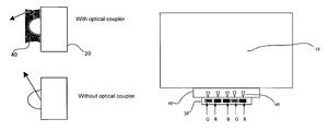
- FIG. 7 depicts a SSLS with and without an optical coupler, according to an embodiment of the present invention.
- FIGS. 7 a - 7 g show examples of SSLS to DOLG coupling, according to embodiments of the present invention.
- FIG. 7 h shows an optical light guide, according to an embodiment of the present invention.
- FIG. 8 depicts a DOLG illuminated from two sides using a SSLS with total internal reflection (TIR) index matching and reflective surfaces, according to an embodiment of the present invention.
- TIR total internal reflection
- FIG. 2 shows an exemplary display backlight assembly using a solid state light source (SSLS) 20 , according to an embodiment of the present invention.
- the SSLS 20 may include any suitable solid state light source, such as, for example, light emitting diodes (LEDs), solid state lasers, or other suitable semi-conductor-based light source.
- the SSLS 20 may include one or more resonant cavity light emitting diodes (RCLED), one or more super luminescent light emitting diodes (SLEDs), or one or more organic LEDs.
- RCLED resonant cavity light emitting diodes
- SLEDs super luminescent light emitting diodes
- the SSLS 20 may include multiple devices (i.e., multiple LEDs) and may include devices that emit light at multiple wavelengths (i.e., a multi-colored array of LEDs).
- a LED-based SSLS 20 may include an array of red LEDs (labeled as “R” in FIGS. 3-6 ), green LEDs (labeled as “G” in FIGS. 3-6 ), and blue LEDs (labeled as “B” in FIGS. 3-6 ).
- FIG. 3 shows a detailed construction of a red, green, blue LED-based SSLS 20 which includes a plurality of RGB LEDs, according to an embodiment of the present invention.
- the separate red, green, and blue LED die are tightly packed (i.e., the spacing between the LED die can be between 1-10,000 microns) to form a RGB array exhibiting a substantially uniform distribution of light.
- FIG. 4 depicts a RGB array SSLS 20 according to an embodiment of the present invention, which includes an optical reflector 30 for directing the emitted light toward the DOLG 10 .
- an improved color gamut may be provided by using a multi-color LED array including, but not limited to, red, blue, green, amber, and cyan LEDs.
- a multi-color LED array including, but not limited to, red, blue, green, amber, and cyan LEDs.
- the multi-color LED array includes red, green, and blue LEDs.
- shown in FIG. 5 includes red, green, blue, amber and cyan LEDs.
- FIG. 6 shows an exemplary embodiment of the present invention wherein the multi-color LEDs are arranged in a slotted cavity 35 in the SSLS 20 .
- the slotted cavity may be coated or formed from highly reflective materials such as aluminum, highly reflective TeflonTM or MgO paint.
- the geometry of the slot efficiently focuses or directs the wide angular distribution of the light emitting from the solid state light sources into the DOLG 10 , through a larger area with narrower light divergence, thus improving its overall luminance.
- the light emitted by the SSLS 20 is more effectively directed into the one or more edges of the DOLG 10 (not shown in FIG. 7 ) by coupling the SSLS 20 and the DOLG 10 together using one or more optical couplers 40 .
- the optical coupler 40 guides more light into the DOLG 10 , resulting in a significant increase in the illumination of the DOLG 10 (e.g., approximately a 50-60% increase).
- the optical coupling of the SSLS-to-DOLG interface reduces the amount of light that is lost by frustrated total internal reflection.
- the optical coupler 40 also reduces the total internal reflection (TIR) absorption loss within and around the SSLS 20 .
- TIR total internal reflection
- the DOLG 10 may be composed of any suitable material, such as, for example, acrylic.
- the optical coupler 40 also reduces the light lost due to back-reflections between the SSLS 20 and the DOLG 10 (i.e., the loss due to fresnel reflection loss).
- fresnel reflection loss at normal incidence is approximated by the following expression: (( n t ⁇ n i )/( n t +n i )) 2 where n t is the index of refraction of the transmitting medium, and where n i is the index of refraction of the incident medium or layer.
- the DOLG/air interface and the light source/air interface where the index of air is approximately 1, and the index of the DOLG 10 is approximately 1.5, each produce approximately 4% reflectance loss.
- light that meets the TIR condition at the optical coupler 40 is directed back into the DOLG 10 , rather than escaping into the air.
- the DOLG 10 and SSLS 20 may be optically coupled together using one or more optical couplers 40 , such as, for example: an optical index matching gel, a tapered pre-collimation light guide (with and without stepped reflectors), a shaped pre-collimation light guide, or an inverse tapered light guide pre-mixer.
- optical couplers 40 such as, for example: an optical index matching gel, a tapered pre-collimation light guide (with and without stepped reflectors), a shaped pre-collimation light guide, or an inverse tapered light guide pre-mixer.
- any of these embodiments of optical couplers may further comprise one or more micro-prisms or other light dispersers.
- FIG. 7 a shows an exemplary display backlight assembly according to an embodiment of the present invention, wherein the SSLS 20 is optically coupled to one or more edges of the DOLG 10 using an optical index matching gel 40 A, typically a silicone compound.
- an optical index matching gel 40 A typically a silicone compound.
- any suitable optical index matching gel may be used in accordance with the present invention, including but not limited to, Metrotek 61180, Thorlabs G608N, Nusil LS-3249, and Nye OCF-452.
- the optical index matching gel 40 A may have an adjustable index of refraction.
- the adjustable index gel is composed of a host material, such as, for example, polysiloxane (silcone), and a dopant material.
- the dopant material may be any suitable material used to increase the mean index of refraction of the gel, such as, for example, a diphenyl or other compound.
- polysiloxanes silicones
- Introducing diphenyldimethyl materials into the polysiloxanes produce higher index of refraction copolymers, which may be used to form index bridges and thus reduce fresnel backreflection losses.
- FIG. 7 b depicts an exemplary display backlight assembly according to an embodiment of the present invention, wherein the DOLG 10 includes one or more pre-formed contoured edges 40 B shaped to mate with at least a portion of the SSLS 20 .
- the pre-formed contour may be shaped in a substantially hemispheric manner to securely fit at least a top portion of the LEDs.
- an optical index matching gel 40 A may be provided at the interface of the contoured edge 40 B and the SSLS 20 .
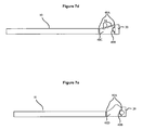
- FIG. 7 c shows an exemplary display backlight assembly according to an embodiment of the present invention, wherein a tapered pre-collimation light guide 40 C is disposed between the DOLG 10 and the SSLS 20 .
- the tapered pre-collimation light guide 40 C may include a contoured edge shaped to mate with at least a portion of the SSLS 20 .
- an optical index matching gel may be used at the interface between the SSLS 20 and the tapered pre-collimation light guide 40 C and/or the interface between the DOLG 10 and the tapered pre-collimation light guide 40 C.
- the tapered pre-collimation light guide 40 C provides for the redirection of light in an angular distribution that may be easily accepted by the DOLG 10 .
- the tapered pre-collimation light guide 40 C improves optical coupling by matching the numerical aperture (NA) of the DOLG 10 , without significantly increasing etendue.
- NA numerical aperture
- the tapered pre-collimation light guide 40 C may be composed of any suitable material, including, but not limited to, cured acrylic resin or cured silicone.
- the efficiency ( ⁇ ) of the light transferred from the SSLS 20 to the DOLG 10 may be approximated by the following transfer efficiency components: ⁇ (geometrical); ⁇ (fresnel); and ⁇ (angular), wherein ⁇ (geometrical) equates to the geometrical loss factor contributing to coupling efficiency; ⁇ (fresnel) equates to the fresnel backreflection loss(es); and ⁇ (angular) equates to the angular distribution and acceptance mismatch losses.
- ⁇ i represents the incident angle of light propagation with respect to the surface normal
- ⁇ t represents the transmitted angle of light propagation
- ⁇ lightguide arcsin(NA)
- m (log(0.5))/(log(cos( ⁇ FWHM )/2)); and where FWHM is the full width at half maximum angle.
- ⁇ FWHM is the angle at which the intensity of the SSLS 20 drops to 50%.
- collimators may be used as efficient angle-to-area converters, including, for example, collimators of several different geometric configurations, such as tapered cones, parabolas, confocal parabolic concentrators, and confocal elliptical concentrators.
- an edge of the tapered pre-collimation light guide 40 C may be contoured to mate with and securely fit at least a portion of the SSLS 20 .
- the tapered pre-collimation light guide 40 C provides for improved brightness uniformity at the edges of the DOLG 10 .
- the tapered pre-collimation light guide 40 C increases the useable uniform area of the DOLG 10 for display purposes.
- the tapered pre-collimation light guide 40 C provides efficient color mixing and decreases banding artifacts caused by non-uniform incidences on the dispersing peening arrangement, prisms, holographic elements, or other dispersing means typically used in conventional liquid crystal display (LCD) light guide panels.
- the angle, length, surface roughness, microstructure, material, index of refraction and/or other characteristics of the tapered pre-collimation light guide 40 C may be optimized for specific applications and improved light guide performance.
- one or more stepped reflectors 50 may be arranged on the top and/or bottom internal sides of the tapered pre-collimation light guide 40 C to improve the color mixing of the SSLS 20 and to provide improved uniformity at the active edge of the DOLG 10 .
- the stepped reflectors 50 may be formed according to a variety of known methods, including, but not limited to, thick layer photo-resist fabrication or precision electroforming using a mold.
- suitable methods may be employed to refine the pitch, trough tolerance, and/or angular precision of the reflectors 50 .
- FIG. 7 e illustrates another exemplary display backlight assembly according to the present invention.
- the assembly includes a shaped (i.e., a non-linear taper) pre-collimation light guide 40 D having a higher order active Bezier or aspheric polynomial.
- the shaped pre-collimation light guide 40 D provides color mixing, uniformity, and flux transfer efficiency for the light passing from the SSLS 20 to the DOLG 10 , and may be composed of any suitable material, such as cured acrylic resin or cured silicone.
- a shaped pre-collimation light guide 40 D may be in the form of a Bezier, or non-uniform Bezier spline, to allow more control over the angular distribution of the source.
- a non-uniform Bezier curve includes control points described through cartesian coordinates in x, y and z, or by an additional weighting parameter w (i.e., the order of the curve), and a knot vector for mapping from parametric space to object space, as represented by the following equation:
- C(u) represents a Bezier curve where u is a parametric parameter, where i represents a Bezier curve of order equal to 0, where n represents the Bezier curve order, where w i represents a control point weighting parameter, where P i represents a control point number, and where N i,p (u) represents a normalized basis function. Accordingly, the curve forms within the bounding control point polygon or complex hull, as follows:
- the shaped pre-collimation light guide 40 D is formed using either a 2D Bezier (i.e., a non-uniform rational Bezier spline or a 3D non-uniform rational Bezier spline surface, the light can be guided in such a manner that collimation and directionality are introduced into the beam, as well as controlled randomization of primary color concentrations.
- a 2D Bezier i.e., a non-uniform rational Bezier spline or a 3D non-uniform rational Bezier spline surface
- the non-uniform Bezier spline surface may be represented by the following expression:
- the DOLG 10 is illuminated by color specific squares spaced accordingly, and the light is propagated from one side of the DOLG 10 to the other without dispersion or redirection to a vertical direction (i.e., a direction from which the corresponding panel is illuminated).
- the control points and weighting knot vectors may be manipulated to provide a high degree of collimation and directionality in the vertical direction with wide dispersion in the horizontal direction to improve color uniformity.
- the Bezier splines are shaped to approximate a confocal parabolic concentrator to efficiently collimate light from the SSLS 20 (e.g., solid state lambertian emitters).
- shaped pre-collimation light guide 40 D arranged as Bezier splines may also include perturbations in the control points to increase randomization of the primary light directional propagation.
- the splines take on general forms which disperse light through negative prescriptions and may include local geometric structures to form enhanced skew rays which cross paths with those of alternate color, such that the net effect at the entrance aperture of the DOLG 10 is a white light or a homogeneously randomized multi primary.
- the shaped pre-collimation light guide 40 D may include contoured edges adapted to mate with the SSLS 20 , as described above and shown in FIG. 7 e .
- an optical index matching gel 40 A may be used to provide additional optical coupling between the interface of the SSLS 20 and the shaped pre-collimation light guide 40 D and/or the interface of the DOLG 10 and the shaped pre-collimation light guide 40 D.
- the shaped pre-collimation light guide 40 D may include one or more stepped reflectors 50 , similar to those described above with respect to FIG. 7 d.
- FIG. 7 f illustrates an embodiment of the present invention wherein the DOLG 10 and the SSLS 20 are coupled by an inverse-tapered light guide pre-mixer 40 E.
- the inverse-tapered light guide pre-mixer 40 E is arranged such that the narrow-end of the taper is coupled to the SSLS 20 and the wide-end of the taper coupled to the DOLG 10 .
- the inverse-tapered light guide pre-mixer 40 E may be composed of any suitable material, such as, for example, cured acrylic resin or cured silicone.
- the inverse-tapered light guide 40 E provides improved coupling efficiency between the SSLS 20 and the DOLG 10 .
- the inverse-tapered light guide 40 E improves the overall brightness of the backlight by further improving conversion of angular distribution into area illumination.
- an inverse-tapered light guide 40 E e.g., cone-shaped light guide
- A semi-angle
- B maximum input angle
- the inverse-tapered light guide pre-mixer 40 E may include micro-prisms.
- the inverse-tapered light guide 40 E may include one or more stepped reflectors 50 on either the upper or lower surface of the inverse-tapered light guide 40 E to redirect light propagation paths to homogenously illuminate the DOLG 10 aperture.
- an optical index matching gel 40 A may be used to provide additional optical coupling between the interface of the SSLS 20 and the inverse-tapered light guide pre-mixer 40 E and/or the interface of the DOLG 10 and the inverse-tapered light guide pre-mixer 40 E.
- FIG. 7 g shows an exemplary display backlight assembly according to the present invention including an optical index matching gasket 40 F which optically couples the DOLG 10 and the SSLS 20 .
- the optical index matching gasket 40 F may be composed of any suitable transparent material, such as, for example, silicone, optically transparent rubber, or other suitable low durometer material.
- the optical index matching gasket 40 F is composed of a molded silicone material, preferably a mean index matched silicone gel cured through a platinum catalyzed addition cure, tin condensation, oxime, or peroxide cure.
- a platinum complex cure may be used to generate to form a reaction between the hydride and vinyl groups of the silicone, thereby forming an ethyl bridge.
- both the optical index matching gasket 40 F and an optical index matching gel 40 A may be used to couple the interface of the DOLG 10 and the SSLS 20 .
- the optical index matching gasket may be shaped to mate with the SSLS 20 and form a light-guiding extension of the DOLG 10 .
- the optical index matching gasket 40 F may be removable.
- FIG. 7 h depicts an exemplary display backlight assembly according to an embodiment of the present invention wherein the optical coupler 40 (e.g., an optical index matching gel 40 A or optical index matching gasket 40 F) includes one or more micro-prism dispersers 60 disposed therein.
- the one or more micro-prism dispersers 60 have a slightly lower or slightly higher index of refraction relative to the optical coupler 40 (or optical index matching gasket 40 F).
- microprism light dispersants of slightly different refractive index than the host material perturb the direction cosines of incoming light rays.
- the optical coupler 40 is composed of an immersion refractive index gel or clear silicone gasket material.
- the micro-prism dispersers 60 re-orient the color-specific light cones emitted from the LED dies to further integrate the combined color contribution of the one or more LED die (labeled R, G, and B in FIG. 7 h ) of the SSLS 20 .
- These three-dimensional pyramidal prisms may shape the light into a fan-like distribution or a two-dimensional intensity spread.
- the micro-prisms dispersers 60 improve lateral mixing between the individual RGB light sources, while still maintaining the light intensity distributions within the acceptance NA of the DOLG 10 .
- the micro-prism dispersers 60 are included in the optical coupler 40 to decrease the integration length required.
- the optical coupler 40 according to this embodiment of the present invention may be an optical index matching gel 40 A, a tapered pre-collimation light guide 40 C, a shaped pre-collimation light guide 40 D, an inverse-tapered light guide pre-mixer 40 E, or an optical index matching gasket 40 F.
- the optical couplers may be composed of acrylic, a transparent optical silicone gasket, or other suitable index matching gel material.
- FIG. 8 shows an exemplary display backlight assembly according to an embodiment of the present invention including a DOLG 10 illuminated with two SSLSs, referred to as SSLS 1 and SSLS 2 .
- SSLS 1 and SSLS 2 are each optically coupled to the DOLG 10 by respective optical couplers 80 A, 80 B.
- the light emitted by SSLS 1 and SSLS 2 passes through optical couplers 80 A, 80 B and illuminates the DOLG 10 .
- some of the light may be lost if it is emitted by SSLS 1 , couples through the DOLG 10 , and is absorbed by SSLS 2 , and/or vice versa.
- the index of refraction of the optical coupler 40 (labeled as IR 1 in FIG. 8 ) is greater than the index of refraction of the DOLG 10 (labeled as IR 2 in FIG. 8 ).
- IR 1 in FIG. 8 the index of refraction of the DOLG 10
- the SSLSs may each include a reflective surface to reflect the light emitted by the opposing SSLS.
- the DOLG 10 may encounter multiple intersections with a dielectric/air interface in a traditional backlight lightguide coupler. With each passage of the light through this interface, attenuation occurs which decreases the luminance of the backlight. Light which passes the lightguide-to-coupler interface must reflect efficiently to allow for re-entry into the light guide.
- a reflective surface such as highly reflective silver, aluminum, or reflective polymers (e.g., the AmodalTM polymers manufactured by Solvay Advanced Polymers) may surround the emitter in the form of a conformly designed primary reflector.
- highly reflective silver, aluminum, or reflective polymers e.g., the AmodalTM polymers manufactured by Solvay Advanced Polymers
Abstract
Description
((n t −n i)/(n t +n i))2
where nt is the index of refraction of the transmitting medium, and
where ni is the index of refraction of the incident medium or layer.
As such, in a conventional arrangement, the DOLG/air interface and the light source/air interface, where the index of air is approximately 1, and the index of the
n gel =[n hostmaterial +n dopantmaterial]5.
For example, polysiloxanes (silicones) have an index of refraction of 1.40 at 25° C. at a wavelength of 589 nm. Introducing diphenyldimethyl materials into the polysiloxanes produce higher index of refraction copolymers, which may be used to form index bridges and thus reduce fresnel backreflection losses.
P(SSLS)transferred=η(geometrical)*η(fresnel)*η(angular)
where η(geometrical)=area of the DOLG (lightguide) aperture/area of the SSLS (lightsource),
where η(fresnel)=1−R; and
where R is the percentage of light backreflected into the optical coupler, as represented by the following expression:
R=((n lightguide −n coupler)2)/((n lightguide +n coupler)2)×100%.
R=((n lightguide−1)2/(n lightguide+1)2×100%
wherein orthogonal incidence by the incoming light is assumed. Light bundles which are off-axis from the normal experience more back reflection loss, and accordingly:
R′=((n lightguide*cos(θi)−n coupler*cos(θt))/(n lightguide*cos(θi)+n coupler*cos(θi)) and
η(angular)=1−(cos(θlightguide))m+1
where θi represents the incident angle of light propagation with respect to the surface normal,
where θt represents the transmitted angle of light propagation,
where θlightguide=arcsin(NA),
where m is dependent on the angular distribution of the source, and defined by the following expression:
m=(log(0.5))/(log(cos(θFWHM)/2)); and
where FWHM is the full width at half maximum angle.
where C(u) represents a Bezier curve where u is a parametric parameter,
where i represents a Bezier curve of order equal to 0,
where n represents the Bezier curve order,
where wi represents a control point weighting parameter,
where Pi represents a control point number, and
where Ni,p(u) represents a normalized basis function.
Accordingly, the curve forms within the bounding control point polygon or complex hull, as follows:

where S(u,v) represents a non-uniform surface with u,v parametric spatial variables,
where Ni,p represents a Bezier spline basis function in a first direction,
where Nj,q represents a Bezier spline basis function in a second direction,
where Pi,j represent the control points,
where Wi,j represents the control point weight parameters,
where m represents the last Bezier order in the first direction, and
where n represents the last Bezier order in the second direction.
2*(A)=(PI/2)−B
where PI represents the ratio of the circumference and the diameter of an angular circle.
s=2*k*sin(θ/2)
where k is the wavevector influenced by index difference and wavelength, and
where θ is the angle of perturbation induced by refraction and the dissimilar dielectric interface boundary shape. The refractive index ratio m=nparticle/nhost=1+mu, where mu is preferably between 0.005 and 0.025 to achieve high light transfer efficiency with improved color uniformity. The deviation angle induced by the micro-site scatter is approximated by delta=2*[sin−1(h/r ′)−sin−1[h/r′*(1+mu)], where (h) is the distance from the normal incident ray passing through the center of the micro-dispersant particle and the actual raypath passing through a chord section of the micro-dispersant. Optionally, the
Claims (58)
Priority Applications (2)
| Application Number | Priority Date | Filing Date | Title |
|---|---|---|---|
| US11/474,187 US8079743B2 (en) | 2005-06-28 | 2006-06-23 | Display backlight with improved light coupling and mixing |
| US11/847,033 US7719021B2 (en) | 2005-06-28 | 2007-08-29 | Light efficient LED assembly including a shaped reflective cavity and method for making same |
Applications Claiming Priority (2)
| Application Number | Priority Date | Filing Date | Title |
|---|---|---|---|
| US69474005P | 2005-06-28 | 2005-06-28 | |
| US11/474,187 US8079743B2 (en) | 2005-06-28 | 2006-06-23 | Display backlight with improved light coupling and mixing |
Related Child Applications (1)
| Application Number | Title | Priority Date | Filing Date |
|---|---|---|---|
| US11/847,033 Continuation-In-Part US7719021B2 (en) | 2005-06-28 | 2007-08-29 | Light efficient LED assembly including a shaped reflective cavity and method for making same |
Publications (2)
| Publication Number | Publication Date |
|---|---|
| US20070081360A1 US20070081360A1 (en) | 2007-04-12 |
| US8079743B2 true US8079743B2 (en) | 2011-12-20 |
Family
ID=37595904
Family Applications (1)
| Application Number | Title | Priority Date | Filing Date |
|---|---|---|---|
| US11/474,187 Active 2026-11-15 US8079743B2 (en) | 2005-06-28 | 2006-06-23 | Display backlight with improved light coupling and mixing |
Country Status (3)
| Country | Link |
|---|---|
| US (1) | US8079743B2 (en) |
| TW (1) | TW200705054A (en) |
| WO (1) | WO2007002476A2 (en) |
Cited By (12)
| Publication number | Priority date | Publication date | Assignee | Title |
|---|---|---|---|---|
| US20090010023A1 (en) * | 2007-07-05 | 2009-01-08 | I2Ic Corporation | Light source having transparent layers |
| US20120275178A1 (en) * | 2011-04-26 | 2012-11-01 | Stephan Lvovich Logunov | Light-coupling optical systems and methods employing light-diffusing optical fibert |
| US20120294036A1 (en) * | 2011-05-19 | 2012-11-22 | Shenzhen China Star Optoelectronics Technology Co. | LED Light-Source Structure and Backlight Module |
| US8348489B2 (en) | 2008-01-30 | 2013-01-08 | Qualcomm Mems Technologies, Inc. | Thin illumination system |
| US8674616B2 (en) | 2008-10-10 | 2014-03-18 | Qualcomm Mems Technologies, Inc. | Distributed illumination system |
| US20140126238A1 (en) * | 2012-11-07 | 2014-05-08 | Wistron Corporation | Light source module and manufacturing method thereof |
| US8721149B2 (en) | 2008-01-30 | 2014-05-13 | Qualcomm Mems Technologies, Inc. | Illumination device having a tapered light guide |
| CN104620041A (en) * | 2012-09-13 | 2015-05-13 | 三菱电机株式会社 | Planar light source device and display device using same |
| US20170141154A1 (en) * | 2015-11-16 | 2017-05-18 | Samsung Electronics Co., Ltd | Light source module and display apparatus having the same |
| US9921356B2 (en) | 2015-09-23 | 2018-03-20 | Apple Inc. | Display Backlight with Light Mixing Structures |
| US10267971B2 (en) | 2015-08-14 | 2019-04-23 | Radiant Opto-Electronics (Suzhou) Co., Ltd. | Light guide film, backlight module and display device having the same |
| DE102019212944A1 (en) * | 2019-08-28 | 2021-03-04 | OSRAM Opto Semiconductors Gesellschaft mit beschränkter Haftung | SEMICONDUCTOR COMPONENT, DEVICE WITH A SEMICONDUCTOR COMPONENT AND A METHOD FOR MANUFACTURING SEMICONDUCTOR COMPONENTS |
Families Citing this family (106)
| Publication number | Priority date | Publication date | Assignee | Title |
|---|---|---|---|---|
| US7750886B2 (en) | 2004-09-27 | 2010-07-06 | Qualcomm Mems Technologies, Inc. | Methods and devices for lighting displays |
| US7607814B2 (en) * | 2006-05-24 | 2009-10-27 | 3M Innovative Properties Company | Backlight with symmetric wedge shaped light guide input portion with specular reflective surfaces |
| US7740387B2 (en) * | 2006-05-24 | 2010-06-22 | 3M Innovative Properties Company | Backlight wedge with side mounted light source |
| US7660509B2 (en) | 2006-05-24 | 2010-02-09 | 3M Innovative Properties Company | Backlight asymmetric light input wedge |
| US7766498B2 (en) | 2006-06-21 | 2010-08-03 | Qualcomm Mems Technologies, Inc. | Linear solid state illuminator |
| US7845841B2 (en) * | 2006-08-28 | 2010-12-07 | Qualcomm Mems Technologies, Inc. | Angle sweeping holographic illuminator |
| KR20080031573A (en) * | 2006-10-04 | 2008-04-10 | 삼성전자주식회사 | Line light source using point light source |
| US7855827B2 (en) | 2006-10-06 | 2010-12-21 | Qualcomm Mems Technologies, Inc. | Internal optical isolation structure for integrated front or back lighting |
| EP1971884A2 (en) * | 2006-10-06 | 2008-09-24 | Qualcomm Mems Technologies, Inc. | Thin light bar and method of manufacturing |
| EP2069838A2 (en) * | 2006-10-06 | 2009-06-17 | Qualcomm Mems Technologies, Inc. | Illumination device with built-in light coupler |
| US8107155B2 (en) | 2006-10-06 | 2012-01-31 | Qualcomm Mems Technologies, Inc. | System and method for reducing visual artifacts in displays |
| US7864395B2 (en) * | 2006-10-27 | 2011-01-04 | Qualcomm Mems Technologies, Inc. | Light guide including optical scattering elements and a method of manufacture |
| TW200827852A (en) * | 2006-12-28 | 2008-07-01 | Ind Tech Res Inst | Coupling device |
| US20080260329A1 (en) * | 2007-04-20 | 2008-10-23 | 3M Innovative Properties Company | Lightguides having curved light injectors |
| US20080260328A1 (en) * | 2007-04-20 | 2008-10-23 | 3M Innovative Properties Company | Led light extraction bar and injection optic for thin lightguide |
| CN101315484B (en) * | 2007-06-01 | 2011-09-28 | 富士迈半导体精密工业(上海)有限公司 | Light source component and back light module unit including the same |
| US8585273B2 (en) * | 2007-07-31 | 2013-11-19 | Rambus Delaware Llc | Illumination assembly including wavelength converting material |
| US20090034230A1 (en) * | 2007-07-31 | 2009-02-05 | Luminus Devices, Inc. | Illumination assembly including wavelength converting material having spatially varying density |
| JP2009058768A (en) * | 2007-08-31 | 2009-03-19 | Showa Denko Kk | Display, and light emitting device |
| KR20100100776A (en) * | 2007-10-09 | 2010-09-15 | 안소니 제이. 니콜 | Light coupling into illuminated films |
| US8434909B2 (en) * | 2007-10-09 | 2013-05-07 | Flex Lighting Ii, Llc | Light emitting display with light mixing within a film |
| CN101418927A (en) * | 2007-10-24 | 2009-04-29 | 富士迈半导体精密工业(上海)有限公司 | Light source assembly |
| US7949213B2 (en) | 2007-12-07 | 2011-05-24 | Qualcomm Mems Technologies, Inc. | Light illumination of displays with front light guide and coupling elements |
| WO2009102731A2 (en) | 2008-02-12 | 2009-08-20 | Qualcomm Mems Technologies, Inc. | Devices and methods for enhancing brightness of displays using angle conversion layers |
| US8654061B2 (en) | 2008-02-12 | 2014-02-18 | Qualcomm Mems Technologies, Inc. | Integrated front light solution |
| US8662727B2 (en) * | 2008-03-19 | 2014-03-04 | I2Ic Corporation | Apparatus for efficiently coupling light from a light source into a thin object |
| WO2009129264A1 (en) | 2008-04-15 | 2009-10-22 | Qualcomm Mems Technologies, Inc. | Light with bi-directional propagation |
| US8118468B2 (en) * | 2008-05-16 | 2012-02-21 | Qualcomm Mems Technologies, Inc. | Illumination apparatus and methods |
| WO2009149118A2 (en) * | 2008-06-04 | 2009-12-10 | Qualcomm Mems Technologies, Inc. | Edge shadow reducing methods for prismatic front light |
| US8002450B2 (en) * | 2008-10-06 | 2011-08-23 | Rambus Inc. | Cavity reflector light injection for flat panel displays |
| US8075165B2 (en) | 2008-10-14 | 2011-12-13 | Ledengin, Inc. | Total internal reflection lens and mechanical retention and locating device |
| US20100157406A1 (en) * | 2008-12-19 | 2010-06-24 | Qualcomm Mems Technologies, Inc. | System and method for matching light source emission to display element reflectivity |
| US8905610B2 (en) | 2009-01-26 | 2014-12-09 | Flex Lighting Ii, Llc | Light emitting device comprising a lightguide film |
| EP2389537A4 (en) | 2009-01-26 | 2015-07-08 | Flex Lighting Ii Llc | Illumination via flexible thin films |
| US8384097B2 (en) | 2009-04-08 | 2013-02-26 | Ledengin, Inc. | Package for multiple light emitting diodes |
| US8598793B2 (en) | 2011-05-12 | 2013-12-03 | Ledengin, Inc. | Tuning of emitter with multiple LEDs to a single color bin |
| US20110032214A1 (en) * | 2009-06-01 | 2011-02-10 | Qualcomm Mems Technologies, Inc. | Front light based optical touch screen |
| US8917962B1 (en) | 2009-06-24 | 2014-12-23 | Flex Lighting Ii, Llc | Method of manufacturing a light input coupler and lightguide |
| CN102483485A (en) * | 2009-08-03 | 2012-05-30 | 高通Mems科技公司 | Microstructures For Light Guide Illumination |
| US20110044056A1 (en) * | 2009-08-21 | 2011-02-24 | Microsoft Corporation | Light collector for an illumination optic |
| US8353615B2 (en) * | 2009-09-02 | 2013-01-15 | Dell Products L.P. | Optically coupled light guide |
| DE102009041537A1 (en) * | 2009-09-15 | 2011-03-24 | Osram Gesellschaft mit beschränkter Haftung | Rod-shaped optical element, in particular in arrangement with light source and waveguide, and method for producing such an element |
| CN102147074A (en) * | 2010-02-10 | 2011-08-10 | 深圳帝光电子有限公司 | Direct type ultrathin LED backlight module |
| KR20110108697A (en) * | 2010-03-29 | 2011-10-06 | 삼성전자주식회사 | Polarizer for organic electro luminescence device and oled including the same |
| US8322884B2 (en) * | 2010-03-31 | 2012-12-04 | Abl Ip Holding Llc | Solid state lighting with selective matching of index of refraction |
| US9080729B2 (en) | 2010-04-08 | 2015-07-14 | Ledengin, Inc. | Multiple-LED emitter for A-19 lamps |
| US8858022B2 (en) | 2011-05-05 | 2014-10-14 | Ledengin, Inc. | Spot TIR lens system for small high-power emitter |
| US9345095B2 (en) | 2010-04-08 | 2016-05-17 | Ledengin, Inc. | Tunable multi-LED emitter module |
| JP2013525955A (en) | 2010-04-16 | 2013-06-20 | フレックス ライティング 2,エルエルシー | Lighting device with film-based light guide |
| US9028123B2 (en) | 2010-04-16 | 2015-05-12 | Flex Lighting Ii, Llc | Display illumination device with a film-based lightguide having stacked incident surfaces |
| JP2011249020A (en) * | 2010-05-24 | 2011-12-08 | Panasonic Corp | Lighting device |
| US9759843B2 (en) * | 2010-06-28 | 2017-09-12 | Axlen, Inc. | Optical beam shaping and polarization selection on LED with wavelength conversion |
| US9103956B2 (en) | 2010-07-28 | 2015-08-11 | Flex Lighting Ii, Llc | Light emitting device with optical redundancy |
| US8702292B2 (en) * | 2010-09-22 | 2014-04-22 | Terralux, Inc. | Linear illumination devices having light guides and LED-based illumination modules |
| US20140049983A1 (en) * | 2010-11-18 | 2014-02-20 | Anthony John Nichol | Light emitting device comprising a lightguide film and aligned coupling lightguides |
| WO2012075384A2 (en) * | 2010-12-04 | 2012-06-07 | 3M Innovative Properties Company | Illumination assembly and method of forming same |
| US8902484B2 (en) | 2010-12-15 | 2014-12-02 | Qualcomm Mems Technologies, Inc. | Holographic brightness enhancement film |
| WO2012106342A2 (en) * | 2011-02-03 | 2012-08-09 | Bayer Healthcare Llc | Component illumination apparatus, systems, and electronic devices and methods of manufacturing and using the same |
| US9645304B2 (en) | 2011-03-09 | 2017-05-09 | Flex Lighting Ii Llc | Directional front illuminating device comprising a film based lightguide with high optical clarity in the light emitting region |
| US9081125B2 (en) | 2011-08-08 | 2015-07-14 | Quarkstar Llc | Illumination devices including multiple light emitting elements |
| US8573823B2 (en) | 2011-08-08 | 2013-11-05 | Quarkstar Llc | Solid-state luminaire |
| CN103858244B (en) | 2011-08-08 | 2018-08-10 | 夸克星有限责任公司 | Lighting device including a plurality of light-emitting elements |
| CN102392963B (en) * | 2011-11-21 | 2014-01-01 | 深圳市华星光电技术有限公司 | Backlight module and liquid crystal display device |
| US8746944B2 (en) | 2011-11-28 | 2014-06-10 | Blackberry Limited | Light guide apparatus having a light source and a reflector |
| TWI477855B (en) * | 2012-01-20 | 2015-03-21 | Au Optronics Corp | Backlight module |
| US10030846B2 (en) | 2012-02-14 | 2018-07-24 | Svv Technology Innovations, Inc. | Face-lit waveguide illumination systems |
| US11032884B2 (en) | 2012-03-02 | 2021-06-08 | Ledengin, Inc. | Method for making tunable multi-led emitter module |
| US9897284B2 (en) | 2012-03-28 | 2018-02-20 | Ledengin, Inc. | LED-based MR16 replacement lamp |
| TW201341727A (en) * | 2012-04-13 | 2013-10-16 | E Lon Optronics Co Ltd | Lateral light source processing module and lighting device using the same thereof |
| TW201341726A (en) * | 2012-04-13 | 2013-10-16 | E Lon Optronics Co Ltd | Diffusing structure and device with light source using the same thereof |
| KR102075922B1 (en) * | 2012-05-10 | 2020-02-11 | 엘지디스플레이 주식회사 | Light Guide Panel and Liquid Display Apparatus using the same |
| TWI505440B (en) * | 2012-06-04 | 2015-10-21 | Lextar Electronics Corp | Light source module |
| JP6091096B2 (en) * | 2012-06-27 | 2017-03-08 | 矢崎総業株式会社 | Vehicle interior lighting device |
| TW201409096A (en) * | 2012-08-17 | 2014-03-01 | 財團法人車輛研究測試中心 | Modular micro-structured light-guiding device |
| WO2014043369A2 (en) | 2012-09-13 | 2014-03-20 | Quarkstar Llc | Devices for workspace illumination |
| WO2014043321A1 (en) | 2012-09-13 | 2014-03-20 | Quarkstar Llc | Illumination systems providing direct and indirect illumination |
| CN103852820A (en) * | 2012-11-28 | 2014-06-11 | 鸿富锦精密工业(深圳)有限公司 | Light guide rod and light emitting diode lighting device |
| DE202012104954U1 (en) * | 2012-12-19 | 2014-03-27 | Zumtobel Lighting Gmbh | illuminated sign |
| CN103018959B (en) * | 2012-12-26 | 2015-12-02 | 深圳市华星光电技术有限公司 | A kind of liquid crystal module |
| EP2951495B1 (en) * | 2013-02-01 | 2017-08-30 | Quarkstar LLC | Illumination devices including multiple light emitting elements |
| EP2864694B1 (en) | 2013-02-08 | 2016-01-20 | Quarkstar LLC | Illumination device providing direct and indirect illumination |
| US9690032B1 (en) | 2013-03-12 | 2017-06-27 | Flex Lighting Ii Llc | Lightguide including a film with one or more bends |
| US9566751B1 (en) | 2013-03-12 | 2017-02-14 | Flex Lighting Ii, Llc | Methods of forming film-based lightguides |
| US11009646B2 (en) | 2013-03-12 | 2021-05-18 | Azumo, Inc. | Film-based lightguide with interior light directing edges in a light mixing region |
| US9234801B2 (en) | 2013-03-15 | 2016-01-12 | Ledengin, Inc. | Manufacturing method for LED emitter with high color consistency |
| WO2014172571A2 (en) | 2013-04-19 | 2014-10-23 | Quarkstar Llc | Illumination devices with adjustable optical elements |
| EP3422059A1 (en) | 2013-07-18 | 2019-01-02 | Quarkstar LLC | Illumination device in which source light injection is non-parallel to device's optical axis |
| FR3009368B1 (en) * | 2013-08-02 | 2015-08-07 | Peugeot Citroen Automobiles Sa | DEVICE FOR LIGHTING AND / OR SIGNALING A VEHICLE, IN PARTICULAR A MOTOR VEHICLE |
| US9354377B2 (en) | 2013-09-17 | 2016-05-31 | Quarkstar Llc | Light guide illumination device with light divergence modifier |
| CA2927191C (en) * | 2013-10-17 | 2022-02-15 | Nanosys, Inc. | Light emitting diode (led) devices |
| US9406654B2 (en) | 2014-01-27 | 2016-08-02 | Ledengin, Inc. | Package for high-power LED devices |
| KR20220054722A (en) * | 2014-05-16 | 2022-05-03 | 코닝 인코포레이티드 | Edge lighted backlight unit for liquid crystal display device |
| EP3224874B1 (en) | 2014-11-26 | 2019-04-24 | LedEngin, Inc. | Compact emitter for warm dimming and color tunable lamp |
| US11035993B2 (en) | 2015-08-14 | 2021-06-15 | S.V.V. Technology Innovations, Inc | Illumination systems employing thin and flexible waveguides with light coupling structures |
| DE202015104882U1 (en) * | 2015-09-15 | 2016-12-16 | Zumtobel Lighting Gmbh | lighting arrangement |
| EP3548799B1 (en) | 2016-12-02 | 2023-04-19 | Ascensia Diabetes Care Holdings AG | Methods and apparatus for illuminating edge portions of a face of an electronic device display lens |
| KR101910010B1 (en) * | 2016-12-12 | 2018-10-19 | 코오롱글로텍주식회사 | Flat lighting apparatus and method for manufacturing the same |
| CN106873071B (en) * | 2017-03-27 | 2019-10-11 | 开发晶照明(厦门)有限公司 | Planar light source device, side entrance back module and display device |
| WO2018182743A1 (en) * | 2017-03-31 | 2018-10-04 | Leia Inc. | Backlight, multiview display and method employing tapered collimator |
| FR3064531B1 (en) * | 2017-03-31 | 2019-04-05 | Saint-Gobain Glass France | GLAZING LIGHTING. |
| KR102615891B1 (en) * | 2017-09-28 | 2023-12-21 | 레이아 인코포레이티드 | Grating-coupled light guide, display system, and method employing optical concentration |
| DE102017223361B4 (en) * | 2017-12-20 | 2022-01-05 | Osram Gmbh | Optical element, light guide, lens body, lens body arrangement and lamp as well as manufacturing process |
| US10575374B2 (en) | 2018-03-09 | 2020-02-25 | Ledengin, Inc. | Package for flip-chip LEDs with close spacing of LED chips |
| WO2020044418A1 (en) * | 2018-08-28 | 2020-03-05 | 三菱電機株式会社 | Light irradiation device |
| WO2020081120A1 (en) | 2018-10-15 | 2020-04-23 | Leia Inc. | Backlight, multiview display and method having a grating spreader |
| US11513274B2 (en) | 2019-08-01 | 2022-11-29 | Azumo, Inc. | Lightguide with a light input edge between lateral edges of a folded strip |
Citations (37)
| Publication number | Priority date | Publication date | Assignee | Title |
|---|---|---|---|---|
| US4903172A (en) * | 1987-09-11 | 1990-02-20 | Schoeniger Karl Heinz | Display construction |
| US5050946A (en) * | 1990-09-27 | 1991-09-24 | Compaq Computer Corporation | Faceted light pipe |
| US5217811A (en) * | 1989-05-18 | 1993-06-08 | At&T Bell Laboratories | Devices featuring silicone elastomers |
| US5581876A (en) | 1995-01-27 | 1996-12-10 | David Sarnoff Research Center, Inc. | Method of adhering green tape to a metal support substrate with a bonding glass |
| US5725808A (en) | 1996-05-23 | 1998-03-10 | David Sarnoff Research Center, Inc. | Multilayer co-fired ceramic compositions and ceramic-on-metal circuit board |
| US5883684A (en) * | 1997-06-19 | 1999-03-16 | Three-Five Systems, Inc. | Diffusively reflecting shield optically, coupled to backlit lightguide, containing LED's completely surrounded by the shield |
| US5953203A (en) | 1997-03-06 | 1999-09-14 | Sarnoff Corporation | Multilayer ceramic circuit boards including embedded capacitors |
| US6270831B2 (en) | 1998-04-30 | 2001-08-07 | Medquest Products, Inc. | Method and apparatus for providing a conductive, amorphous non-stick coating |
| US6274890B1 (en) * | 1997-01-15 | 2001-08-14 | Kabushiki Kaisha Toshiba | Semiconductor light emitting device and its manufacturing method |
| US6455930B1 (en) | 1999-12-13 | 2002-09-24 | Lamina Ceramics, Inc. | Integrated heat sinking packages using low temperature co-fired ceramic metal circuit board technology |
| US6518502B2 (en) | 2001-05-10 | 2003-02-11 | Lamina Ceramics, In | Ceramic multilayer circuit boards mounted on a patterned metal support substrate |
| US20030049007A1 (en) * | 2001-09-13 | 2003-03-13 | Matthew Sommers | Optical wave guide |
| US6536909B1 (en) | 1998-08-26 | 2003-03-25 | Editions Publicite Excelsior | Display backlights |
| US20030219207A1 (en) * | 2002-05-22 | 2003-11-27 | The Boeing Company | Fiber optic LED illuminator |
| US20040043693A1 (en) | 2002-08-30 | 2004-03-04 | Fujitsu Hitachi Plasma Display Limited | Method of manufacturing a plasma display panel |
| US20040066645A1 (en) * | 2002-10-03 | 2004-04-08 | John Graf | Bulk diffuser for flat panel display |
| US20040071437A1 (en) * | 2002-04-10 | 2004-04-15 | Yuuki Tamura | Optical waveguide plate for surface light emitting apparatus and surface light emitting apparatus using the optical waveguide plate |
| US20040109306A1 (en) | 2002-12-05 | 2004-06-10 | Kyoung-Don Lee | Backlight assembly and liquid crystal display apparatus having the same |
| US6805456B2 (en) | 2001-09-12 | 2004-10-19 | Citizen Electronics Co., Ltd. | Planar light source unit |
| US20040246744A1 (en) * | 2003-03-26 | 2004-12-09 | Krupa Robert J. | Compact, high-efficiency, high-power solid state light source using a single solid state light-emitting device |
| US20050007756A1 (en) | 2003-07-09 | 2005-01-13 | Chunghwa Picture Tubes, Ltd. | Reflecting apparatus for backlight module of flat panel display |
| US6854854B2 (en) | 2001-04-10 | 2005-02-15 | Koninklijke Philips Electronics N.V. | Illumination system and display device |
| WO2005015646A1 (en) * | 2003-08-07 | 2005-02-17 | Matsushita Electric Industrial Co., Ltd. | Led illumination light source |
| US20050063187A1 (en) | 2003-09-23 | 2005-03-24 | Weng Lee Kong | Ceramic packaging for high brightness LED devices |
| US20050093146A1 (en) | 2003-10-30 | 2005-05-05 | Kensho Sakano | Support body for semiconductor element, method for manufacturing the same and semiconductor device |
| US20050121686A1 (en) | 2003-12-09 | 2005-06-09 | Bernd Keller | Semiconductor light emitting devices and submounts and methods for forming the same |
| US20060158901A1 (en) * | 2005-01-19 | 2006-07-20 | Chih-Yuan Wang | Backlight module with combinative light source and device of changing color of illumination |
| US7098483B2 (en) | 2003-05-05 | 2006-08-29 | Lamina Ceramics, Inc. | Light emitting diodes packaged for high temperature operation |
| WO2006132174A1 (en) | 2005-06-07 | 2006-12-14 | Pentax Corporation | Sharing traceability management system |
| US20060285356A1 (en) * | 2005-06-21 | 2006-12-21 | K-Bridge Electronics Co., Ltd. | Side-edge backlight module dimming pack |
| US20070007558A1 (en) | 2005-06-27 | 2007-01-11 | Mazzochette Joseph B | Light emitting diode package and method for making same |
| US7163331B2 (en) * | 2002-08-30 | 2007-01-16 | Sharp Kabushiki Kaisha | Lighting unit and display device |
| US7172319B2 (en) * | 2004-03-30 | 2007-02-06 | Illumination Management Solutions, Inc. | Apparatus and method for improved illumination area fill |
| US7217025B2 (en) * | 2002-11-04 | 2007-05-15 | Samsung Electronics Co., Ltd. | Backlight unit |
| US20070158674A1 (en) | 2006-01-06 | 2007-07-12 | Yuichi Taguchi | Light emitting device and manufacturing method thereof |
| US20070189007A1 (en) | 2004-03-26 | 2007-08-16 | Keiji Nishimoto | Led mounting module, led module, manufacturing method of led mounting module, and manufacturing method of led module |
| US7293906B2 (en) * | 2005-05-23 | 2007-11-13 | Avago Technologies Ecbu Ip (Singapore) Pte Ltd | Light source adapted for LCD back-lit displays |
Family Cites Families (8)
| Publication number | Priority date | Publication date | Assignee | Title |
|---|---|---|---|---|
| US5867241A (en) * | 1995-04-28 | 1999-02-02 | Rockwell International | Liquid crystal display lamination with silicone gel adhesive |
| US6712481B2 (en) * | 1995-06-27 | 2004-03-30 | Solid State Opto Limited | Light emitting panel assemblies |
| US6104454A (en) * | 1995-11-22 | 2000-08-15 | Hitachi, Ltd | Liquid crystal display |
| US6592234B2 (en) * | 2001-04-06 | 2003-07-15 | 3M Innovative Properties Company | Frontlit display |
| US6874926B2 (en) * | 2001-11-26 | 2005-04-05 | Nokia Corporation | Illumination system for an electronic device |
| KR100698046B1 (en) * | 2002-12-24 | 2007-03-23 | 엘지.필립스 엘시디 주식회사 | Backlight Unit Assembly |
| US7052168B2 (en) * | 2003-12-17 | 2006-05-30 | 3M Innovative Properties Company | Illumination device |
| JP4489423B2 (en) * | 2003-12-26 | 2010-06-23 | シャープ株式会社 | Backlight and liquid crystal display device |
-
2006
- 2006-06-23 WO PCT/US2006/024593 patent/WO2007002476A2/en active Application Filing
- 2006-06-23 US US11/474,187 patent/US8079743B2/en active Active
- 2006-06-28 TW TW095123365A patent/TW200705054A/en unknown
Patent Citations (38)
| Publication number | Priority date | Publication date | Assignee | Title |
|---|---|---|---|---|
| US4903172A (en) * | 1987-09-11 | 1990-02-20 | Schoeniger Karl Heinz | Display construction |
| US5217811A (en) * | 1989-05-18 | 1993-06-08 | At&T Bell Laboratories | Devices featuring silicone elastomers |
| US5050946A (en) * | 1990-09-27 | 1991-09-24 | Compaq Computer Corporation | Faceted light pipe |
| US5581876A (en) | 1995-01-27 | 1996-12-10 | David Sarnoff Research Center, Inc. | Method of adhering green tape to a metal support substrate with a bonding glass |
| US5725808A (en) | 1996-05-23 | 1998-03-10 | David Sarnoff Research Center, Inc. | Multilayer co-fired ceramic compositions and ceramic-on-metal circuit board |
| US6274890B1 (en) * | 1997-01-15 | 2001-08-14 | Kabushiki Kaisha Toshiba | Semiconductor light emitting device and its manufacturing method |
| US5953203A (en) | 1997-03-06 | 1999-09-14 | Sarnoff Corporation | Multilayer ceramic circuit boards including embedded capacitors |
| US5883684A (en) * | 1997-06-19 | 1999-03-16 | Three-Five Systems, Inc. | Diffusively reflecting shield optically, coupled to backlit lightguide, containing LED's completely surrounded by the shield |
| US6270831B2 (en) | 1998-04-30 | 2001-08-07 | Medquest Products, Inc. | Method and apparatus for providing a conductive, amorphous non-stick coating |
| US6536909B1 (en) | 1998-08-26 | 2003-03-25 | Editions Publicite Excelsior | Display backlights |
| US6455930B1 (en) | 1999-12-13 | 2002-09-24 | Lamina Ceramics, Inc. | Integrated heat sinking packages using low temperature co-fired ceramic metal circuit board technology |
| US6854854B2 (en) | 2001-04-10 | 2005-02-15 | Koninklijke Philips Electronics N.V. | Illumination system and display device |
| US6518502B2 (en) | 2001-05-10 | 2003-02-11 | Lamina Ceramics, In | Ceramic multilayer circuit boards mounted on a patterned metal support substrate |
| US6805456B2 (en) | 2001-09-12 | 2004-10-19 | Citizen Electronics Co., Ltd. | Planar light source unit |
| US20030049007A1 (en) * | 2001-09-13 | 2003-03-13 | Matthew Sommers | Optical wave guide |
| US20040071437A1 (en) * | 2002-04-10 | 2004-04-15 | Yuuki Tamura | Optical waveguide plate for surface light emitting apparatus and surface light emitting apparatus using the optical waveguide plate |
| US20030219207A1 (en) * | 2002-05-22 | 2003-11-27 | The Boeing Company | Fiber optic LED illuminator |
| US7163331B2 (en) * | 2002-08-30 | 2007-01-16 | Sharp Kabushiki Kaisha | Lighting unit and display device |
| US20040043693A1 (en) | 2002-08-30 | 2004-03-04 | Fujitsu Hitachi Plasma Display Limited | Method of manufacturing a plasma display panel |
| US20040066645A1 (en) * | 2002-10-03 | 2004-04-08 | John Graf | Bulk diffuser for flat panel display |
| US7217025B2 (en) * | 2002-11-04 | 2007-05-15 | Samsung Electronics Co., Ltd. | Backlight unit |
| US20040109306A1 (en) | 2002-12-05 | 2004-06-10 | Kyoung-Don Lee | Backlight assembly and liquid crystal display apparatus having the same |
| US20040246744A1 (en) * | 2003-03-26 | 2004-12-09 | Krupa Robert J. | Compact, high-efficiency, high-power solid state light source using a single solid state light-emitting device |
| US7098483B2 (en) | 2003-05-05 | 2006-08-29 | Lamina Ceramics, Inc. | Light emitting diodes packaged for high temperature operation |
| US20050007756A1 (en) | 2003-07-09 | 2005-01-13 | Chunghwa Picture Tubes, Ltd. | Reflecting apparatus for backlight module of flat panel display |
| WO2005015646A1 (en) * | 2003-08-07 | 2005-02-17 | Matsushita Electric Industrial Co., Ltd. | Led illumination light source |
| US7235817B2 (en) * | 2003-08-07 | 2007-06-26 | Matsushita Electric Industrial Co., Ltd. | LED Lamp |
| US20050063187A1 (en) | 2003-09-23 | 2005-03-24 | Weng Lee Kong | Ceramic packaging for high brightness LED devices |
| US20050093146A1 (en) | 2003-10-30 | 2005-05-05 | Kensho Sakano | Support body for semiconductor element, method for manufacturing the same and semiconductor device |
| US20050121686A1 (en) | 2003-12-09 | 2005-06-09 | Bernd Keller | Semiconductor light emitting devices and submounts and methods for forming the same |
| US20070189007A1 (en) | 2004-03-26 | 2007-08-16 | Keiji Nishimoto | Led mounting module, led module, manufacturing method of led mounting module, and manufacturing method of led module |
| US7172319B2 (en) * | 2004-03-30 | 2007-02-06 | Illumination Management Solutions, Inc. | Apparatus and method for improved illumination area fill |
| US20060158901A1 (en) * | 2005-01-19 | 2006-07-20 | Chih-Yuan Wang | Backlight module with combinative light source and device of changing color of illumination |
| US7293906B2 (en) * | 2005-05-23 | 2007-11-13 | Avago Technologies Ecbu Ip (Singapore) Pte Ltd | Light source adapted for LCD back-lit displays |
| WO2006132174A1 (en) | 2005-06-07 | 2006-12-14 | Pentax Corporation | Sharing traceability management system |
| US20060285356A1 (en) * | 2005-06-21 | 2006-12-21 | K-Bridge Electronics Co., Ltd. | Side-edge backlight module dimming pack |
| US20070007558A1 (en) | 2005-06-27 | 2007-01-11 | Mazzochette Joseph B | Light emitting diode package and method for making same |
| US20070158674A1 (en) | 2006-01-06 | 2007-07-12 | Yuichi Taguchi | Light emitting device and manufacturing method thereof |
Cited By (22)
| Publication number | Priority date | Publication date | Assignee | Title |
|---|---|---|---|---|
| US20090010023A1 (en) * | 2007-07-05 | 2009-01-08 | I2Ic Corporation | Light source having transparent layers |
| US9395479B2 (en) | 2008-01-30 | 2016-07-19 | Qualcomm Mems Technologies, Inc. | Illumination device having a tapered light guide |
| US8348489B2 (en) | 2008-01-30 | 2013-01-08 | Qualcomm Mems Technologies, Inc. | Thin illumination system |
| US8721149B2 (en) | 2008-01-30 | 2014-05-13 | Qualcomm Mems Technologies, Inc. | Illumination device having a tapered light guide |
| US8740439B2 (en) | 2008-01-30 | 2014-06-03 | Qualcomm Mems Technologies, Inc. | Thin illumination system |
| US9448353B2 (en) | 2008-01-30 | 2016-09-20 | Qualcomm Mems Technologies, Inc. | Illumination device having a tapered light guide |
| US9244212B2 (en) | 2008-01-30 | 2016-01-26 | Qualcomm Mems Technologies, Inc. | Illumination device having a tapered light guide |
| US8674616B2 (en) | 2008-10-10 | 2014-03-18 | Qualcomm Mems Technologies, Inc. | Distributed illumination system |
| US20120275178A1 (en) * | 2011-04-26 | 2012-11-01 | Stephan Lvovich Logunov | Light-coupling optical systems and methods employing light-diffusing optical fibert |
| US8724942B2 (en) * | 2011-04-26 | 2014-05-13 | Corning Incorporated | Light-coupling optical systems and methods employing light-diffusing optical fiber |
| US20120294036A1 (en) * | 2011-05-19 | 2012-11-22 | Shenzhen China Star Optoelectronics Technology Co. | LED Light-Source Structure and Backlight Module |
| US8845171B2 (en) * | 2011-05-19 | 2014-09-30 | Shenzhen China Star Optoelectronics Technology Co., Ltd. | LED light-source structure and backlight module |
| US9500795B2 (en) | 2012-09-13 | 2016-11-22 | Mitsubishi Electric Corporation | Area light source device and display device using same |
| CN104620041A (en) * | 2012-09-13 | 2015-05-13 | 三菱电机株式会社 | Planar light source device and display device using same |
| CN104620041B (en) * | 2012-09-13 | 2016-09-21 | 三菱电机株式会社 | Planar light source device and use the display device of this planar light source device |
| US20140126238A1 (en) * | 2012-11-07 | 2014-05-08 | Wistron Corporation | Light source module and manufacturing method thereof |
| US10267971B2 (en) | 2015-08-14 | 2019-04-23 | Radiant Opto-Electronics (Suzhou) Co., Ltd. | Light guide film, backlight module and display device having the same |
| TWI660206B (en) * | 2015-08-14 | 2019-05-21 | 大陸商瑞儀光電(蘇州)有限公司 | Backlight module and display device |
| US9921356B2 (en) | 2015-09-23 | 2018-03-20 | Apple Inc. | Display Backlight with Light Mixing Structures |
| US20170141154A1 (en) * | 2015-11-16 | 2017-05-18 | Samsung Electronics Co., Ltd | Light source module and display apparatus having the same |
| US10204962B2 (en) * | 2015-11-16 | 2019-02-12 | Samsung Electronics Co., Ltd. | Light source module and display apparatus having the same |
| DE102019212944A1 (en) * | 2019-08-28 | 2021-03-04 | OSRAM Opto Semiconductors Gesellschaft mit beschränkter Haftung | SEMICONDUCTOR COMPONENT, DEVICE WITH A SEMICONDUCTOR COMPONENT AND A METHOD FOR MANUFACTURING SEMICONDUCTOR COMPONENTS |
Also Published As
| Publication number | Publication date |
|---|---|
| WO2007002476A2 (en) | 2007-01-04 |
| TW200705054A (en) | 2007-02-01 |
| WO2007002476A3 (en) | 2009-04-30 |
| US20070081360A1 (en) | 2007-04-12 |
Similar Documents
| Publication | Publication Date | Title |
|---|---|---|
| US8079743B2 (en) | Display backlight with improved light coupling and mixing | |
| US20210286118A1 (en) | Slim waveguide coupling apparatus and method | |
| KR102353695B1 (en) | Privacy Display and Dual-Mode Privacy Display System | |
| US7891852B2 (en) | Illumination system using phosphor remote from light source | |
| US7385653B2 (en) | LED package and backlight assembly for LCD comprising the same | |
| US8120726B2 (en) | Surface light source device and display | |
| US8301002B2 (en) | Slim waveguide coupling apparatus and method | |
| US8136955B2 (en) | Illumination system and display including same | |
| US9110199B2 (en) | Backlight module and liquid crystal display | |
| JP4856261B2 (en) | Light guide for collimating light, method for improving collimation of light guide, backlight, and display device | |
| US7967493B2 (en) | Light guide plate and backlight module using the same | |
| TW201506503A (en) | Flat light guide | |
| US9429700B2 (en) | Backlight module | |
| KR20030064258A (en) | Light guide plate, light source device equipped therewith and display device | |
| WO2020000729A1 (en) | Reflective sheet, side-entry backlight module and liquid crystal display | |
| US8462293B2 (en) | Illuminating device and liquid crystal display device | |
| WO2019000987A1 (en) | Backlight source and manufacturing method therefor and display device | |
| KR20090090926A (en) | Backlight unit | |
| TW200411271A (en) | Light guide plate and back light system with the same | |
| US20210088711A1 (en) | Wedge lightguide | |
| US9103955B2 (en) | Backlight module with light guide plate with light sources, and liquid crystal display apparatus with such module | |
| US20100254159A1 (en) | Brightness enhancement film and backlight module | |
| US9864124B2 (en) | Light generation member including light diffusion member and display apparatus having the same | |
| KR100869147B1 (en) | Light guide panel for back light unit | |
| Wang et al. | P‐65: A Novel Highly CoNimating Backlight Module Using a Double Wedge‐Shaped Light Guide Plate |
Legal Events
| Date | Code | Title | Description |
|---|---|---|---|
| AS | Assignment |
Owner name: LAMINA CERAMICS, INC., NEW JERSEY Free format text: ASSIGNMENT OF ASSIGNORS INTEREST;ASSIGNORS:BAILEY, EDWARD;MAZZOCHETTE, JOSEPH B.;BURDALSKI, ROBERT J.;AND OTHERS;REEL/FRAME:019523/0604 Effective date: 20061212 |
|
| AS | Assignment |
Owner name: LAMINA LIGHTING, INC., NEW JERSEY Free format text: CHANGE OF NAME;ASSIGNOR:LAMINA CERAMICS, INC.;REEL/FRAME:019843/0536 Effective date: 20060614 Owner name: LAMINA LIGHTING, INC.,NEW JERSEY Free format text: CHANGE OF NAME;ASSIGNOR:LAMINA CERAMICS, INC.;REEL/FRAME:019843/0536 Effective date: 20060614 |
|
| AS | Assignment |
Owner name: LIGHTING SCIENCE GROUP CORPORATION, FLORIDA Free format text: ASSIGNMENT OF ASSIGNORS INTEREST;ASSIGNORS:LAMINA LIGHTING, INC.;LLI ACQUISITION, INC.;REEL/FRAME:023141/0517 Effective date: 20080729 Owner name: LIGHTING SCIENCE GROUP CORPORATION,FLORIDA Free format text: ASSIGNMENT OF ASSIGNORS INTEREST;ASSIGNORS:LAMINA LIGHTING, INC.;LLI ACQUISITION, INC.;REEL/FRAME:023141/0517 Effective date: 20080729 |
|
| AS | Assignment |
Owner name: WELLS FARGO BANK, NATIONAL ASSOCIATION, FLORIDA Free format text: SECURITY AGREEMENT;ASSIGNOR:LIGHTING SCIENCE GROUP CORPORATION;REEL/FRAME:026109/0019 Effective date: 20101122 |
|
| AS | Assignment |
Owner name: ARES CAPITAL CORPORATION, NEW YORK Free format text: SECURITY AGREEMENT;ASSIGNOR:LIGHTING SCIENCE GROUP CORPORATION;REEL/FRAME:026940/0875 Effective date: 20110920 |
|
| STCF | Information on status: patent grant |
Free format text: PATENTED CASE |
|
| FEPP | Fee payment procedure |
Free format text: PAT HOLDER CLAIMS SMALL ENTITY STATUS, ENTITY STATUS SET TO SMALL (ORIGINAL EVENT CODE: LTOS); ENTITY STATUS OF PATENT OWNER: SMALL ENTITY |
|
| AS | Assignment |
Owner name: LIGHTING SCIENCE GROUP CORPORATION, FLORIDA Free format text: RELEASE BY SECURED PARTY;ASSIGNOR:WELLS FARGO BANK, NATIONAL ASSOCIATION;REEL/FRAME:032520/0074 Effective date: 20140219 |
|
| AS | Assignment |
Owner name: LIGHTING SCIENCE GROUP CORPORATION, FLORIDA Free format text: RELEASE BY SECURED PARTY;ASSIGNOR:ARES CAPITAL CORPORATION;REEL/FRAME:032527/0427 Effective date: 20140219 |
|
| AS | Assignment |
Owner name: FCC, LLC D/B/A FIRST CAPITAL, AS AGENT, GEORGIA Free format text: SECURITY INTEREST;ASSIGNORS:LIGHTING SCIENCE GROUP CORPORATION;BIOLOGICAL ILLUMINATION, LLC;REEL/FRAME:032765/0910 Effective date: 20140425 |
|
| AS | Assignment |
Owner name: MEDLEY CAPTIAL CORPORATION, AS AGENT, NEW YORK Free format text: SECURITY INTEREST;ASSIGNORS:LIGHTING SCIENCE GROUP CORPORATION;BIOLOGICAL ILLUMINATION, LLC;REEL/FRAME:033072/0395 Effective date: 20140219 |
|
| AS | Assignment |
Owner name: ACF FINCO I LP, NEW YORK Free format text: ASSIGNMENT AND ASSUMPTION OF SECURITY INTERESTS IN PATENTS;ASSIGNOR:FCC, LLC D/B/A FIRST CAPITAL;REEL/FRAME:035774/0632 Effective date: 20150518 |
|
| FPAY | Fee payment |
Year of fee payment: 4 |
|
| AS | Assignment |
Owner name: BIOLOGICAL ILLUMINATION, LLC, A DELAWARE LIMITED L Free format text: RELEASE BY SECURED PARTY;ASSIGNOR:ACF FINCO I LP, A DELAWARE LIMITED PARTNERSHIP;REEL/FRAME:042340/0471 Effective date: 20170425 Owner name: LIGHTING SCIENCE GROUP CORPORATION, A DELAWARE COR Free format text: RELEASE BY SECURED PARTY;ASSIGNOR:ACF FINCO I LP, A DELAWARE LIMITED PARTNERSHIP;REEL/FRAME:042340/0471 Effective date: 20170425 |
|
| AS | Assignment |
Owner name: BIOLOGICAL ILLUMINATION, LLC, A DELAWARE LIMITED L Free format text: RELEASE BY SECURED PARTY;ASSIGNOR:MEDLEY CAPITAL CORPORATION;REEL/FRAME:048018/0515 Effective date: 20180809 Owner name: LIGHTING SCIENCE GROUP CORPORATION, A DELAWARE COR Free format text: RELEASE BY SECURED PARTY;ASSIGNOR:MEDLEY CAPITAL CORPORATION;REEL/FRAME:048018/0515 Effective date: 20180809 |
|
| MAFP | Maintenance fee payment |
Free format text: PAYMENT OF MAINTENANCE FEE, 8TH YR, SMALL ENTITY (ORIGINAL EVENT CODE: M2552); ENTITY STATUS OF PATENT OWNER: SMALL ENTITY Year of fee payment: 8 |
|
| MAFP | Maintenance fee payment |
Free format text: PAYMENT OF MAINTENANCE FEE, 12TH YR, SMALL ENTITY (ORIGINAL EVENT CODE: M2553); ENTITY STATUS OF PATENT OWNER: SMALL ENTITY Year of fee payment: 12 |