US8077620B2 - Methods and apparatuses for processing packets in a credit-based flow control scheme - Google Patents
Methods and apparatuses for processing packets in a credit-based flow control scheme Download PDFInfo
- Publication number
- US8077620B2 US8077620B2 US12/247,845 US24784508A US8077620B2 US 8077620 B2 US8077620 B2 US 8077620B2 US 24784508 A US24784508 A US 24784508A US 8077620 B2 US8077620 B2 US 8077620B2
- Authority
- US
- United States
- Prior art keywords
- packet descriptor
- flow control
- processing
- packet
- queue
- Prior art date
- Legal status (The legal status is an assumption and is not a legal conclusion. Google has not performed a legal analysis and makes no representation as to the accuracy of the status listed.)
- Expired - Fee Related, expires
Links
Images


Classifications
-
- H—ELECTRICITY
- H04—ELECTRIC COMMUNICATION TECHNIQUE
- H04L—TRANSMISSION OF DIGITAL INFORMATION, e.g. TELEGRAPHIC COMMUNICATION
- H04L47/00—Traffic control in data switching networks
- H04L47/10—Flow control; Congestion control
- H04L47/39—Credit based
-
- H—ELECTRICITY
- H04—ELECTRIC COMMUNICATION TECHNIQUE
- H04L—TRANSMISSION OF DIGITAL INFORMATION, e.g. TELEGRAPHIC COMMUNICATION
- H04L47/00—Traffic control in data switching networks
- H04L47/10—Flow control; Congestion control
-
- H—ELECTRICITY
- H04—ELECTRIC COMMUNICATION TECHNIQUE
- H04L—TRANSMISSION OF DIGITAL INFORMATION, e.g. TELEGRAPHIC COMMUNICATION
- H04L47/00—Traffic control in data switching networks
- H04L47/10—Flow control; Congestion control
- H04L47/32—Flow control; Congestion control by discarding or delaying data units, e.g. packets or frames
Definitions
- the invention relates generally to credit-based flow control and more specifically relates to processing packets in a credit-based flow control scheme.
- a flow control scheme is typically used to prevent the transmitter from transmitting additional data to the receiver when the receiver is not able to receive the additional data.
- the receiver issues credits against which the transmitter may transmit data to the receiver. The transmitter may not transmit data to the receiver if doing so would consume more than the available credit. As the receiver becomes able to receive additional data, the receiver issues additional credits to the transmitter.
- PCI Peripheral Component Interconnect Express
- a data transmission is associated with a credit type for flow control purposes.
- a receiving device initially advertises credits available for each flow control credit type. When a transmitting device transmits packets of a particular credit type to the receiving device, the transmitting device uses up credits of the particular credit type. After the receiving device finishes processing the packets, the receiving device signals the transmitting device to restore the available credit.
- a PCI Express device can comprise multiple entities and their corresponding one or more functions. Each function (or entity) can initiate a request at the PCI Express Application Layer that results in the transmission of multiple packets (that also uses up credits of the corresponding credit type). Although multiple packets may be generated in a request, the PCI Express device begins to transmit packets even if there are not enough credits to complete the processing of the request.
- the PCI Express device verifies that there is sufficient credit available before transmitting each packet. If sufficient credit is not available to transmit a packet, processing of the request is blocked. However, this causes processing of a second request to be stalled even if the second request would use a second credit type that is available, and the PCI Express device would thus be able to transmit packets generated from the second request. Stalling the processing of the second request leads to degraded performance of the PCI Express device just as maintaining high performance of the PCI Express device is becoming more critical in today's demanding data processing applications.
- a request can generally be seen as comprising a “packet descriptor” that describes packets to be transmitted for the request.
- the first packet descriptor is associated with a first flow control credit type
- the second packet descriptor is associated with a second flow control credit type.
- the second packet descriptor is selected for processing based on the first flow control credit type and the second flow control credit type. Accordingly, processing of the second packet descriptor is no longer stalled, and performance is improved as a result.
- a method for processing a second packet descriptor before processing of a first packet descriptor has completed.
- the first packet descriptor is associated with a first flow control credit type
- the second packet descriptor is associated with a second flow control credit type.
- the method comprises processing the first packet descriptor and stalling the processing of the second packet descriptor.
- the method also comprises selecting, after a period of time, the second packet descriptor for processing based on the first flow control credit type and the second flow control credit type. Additionally, the method comprises processing the second packet descriptor.
- Another aspect hereof provides an apparatus for processing a second packet descriptor before processing of a first packet descriptor has completed.
- the first packet descriptor is associated with a first flow control credit type
- the second packet descriptor is associated with a second flow control credit type.
- the apparatus comprises a processing element for processing the first packet descriptor and the second packet descriptor.
- the apparatus also comprises a stalling element for stalling the processing of the second packet descriptor.
- the apparatus comprises a selecting element for selecting, after a period of time, the second packet descriptor for processing based on the first flow control credit type and the second flow control credit type.
- FIG. 1 is a flowchart describing an exemplary method in accordance with features and aspects hereof for processing a second packet descriptor before processing of a first packet descriptor has completed.
- FIG. 2 is a flowchart describing exemplary additional details for selecting the second packet descriptor for processing in accordance with features and aspects hereof.
- FIG. 3 is a flowchart describing alternative exemplary details for selecting the second packet descriptor for processing in accordance with features and aspects hereof.
- FIG. 4 is a block diagram of an exemplary apparatus in accordance with features and aspects hereof for processing a second packet descriptor before processing of a first packet descriptor has completed.
- FIG. 5 is a block diagram describing exemplary additional details of a queue processor in accordance with features and aspects hereof.
- FIG. 6 is a block diagram describing exemplary additional details of a packet descriptor in accordance with features and aspects hereof.
- FIG. 7 is a block diagram describing exemplary additional details of a queue in accordance with features and aspects hereof.
- FIG. 8 is a block diagram describing alternative exemplary details of queues in accordance with features and aspects hereof.
- FIG. 9 is a block diagram describing alternative exemplary details of queues in accordance with features and aspects hereof.
- FIG. 10 is a diagram describing a deadlock condition.
- FIG. 11 is a diagram describing the deadlock condition having been corrected in accordance with features and aspects hereof.
- FIG. 1 is a flowchart describing an exemplary method in accordance with features and aspects hereof for processing a second packet descriptor (“PD”) before processing of a first PD has completed.
- the first PD is associated with a first flow control credit type (“FCCT”)
- FCCT flow control credit type
- the second PD is associated with a second FCCT.
- a processor begins processing the first PD. While the processor processes the first PD, the processor stalls at step 120 processing of the second PD.
- the processor selects, after a period of time, the second PD that has been stalled for processing. The step of selecting may be based on the first FCCT and the second FCCT as will be described in greater detail.
- the processor then updates the first PD to reflect a status of the processing of the first PD.
- the processor may generate multiple packets based on a single PD. Accordingly, the processor may have finished transmitting/processing a number of packets when the second PD is selected for processing after the period time. Step 140 thus ensures that the number of transmitted/processed packets is reflected in the first PD, allowing the processor to properly process the first PD at a later time.
- a first PD may describe that 2000 bytes of remote data starting at remote address 3500 is to be read into a local buffer starting at local address 1000 .
- packets for reading the first 500 bytes of remote data have been transmitted when the processor selects the second PD for processing.
- the processor would then update the first PD to reflect that 500 bytes of remote data have been read, and/or that 1500 bytes of remote data starting at remote address 4000 remain to be read into the local buffer starting at local address 1500 .
- the processor begins processing the selected second PD.
- FIG. 2 is a flowchart describing exemplary additional details for selecting the second PD in step 130 of FIG. 1 for processing in accordance with features and aspects hereof.
- the processor chooses the second PD from a number of PDs.
- the PDs may be arranged in a variety of ways, some of which will be described in greater detail.
- the PDs may be arranged in queues each with PDs associated with a particular function. It will be understood that packets of a “function” may be more generally defined as a group of packets whose sequence of processing should not be reordered.
- a first queue may comprise the first PD and a second queue may comprise the second PD.
- the processor may choose the second PD from PDs of the second queue so that the first and the second PDs are associated with different functions.
- the processor checks that the first FCCT associated with the first PD is different from the second FCCT associated with the second PD. If the two PDs are associated with the same FCCT, the processor repeats the steps from 210 and chooses another PD from the second queue and/or from a third queue.
- FIG. 3 is a flowchart describing alternative exemplary details for selecting the second PD in step 130 of FIG. 1 for processing in accordance with features and aspects hereof.
- the processor likewise chooses the second PD from a number of PDs.
- the PDs may alternatively be arranged in queues each with PDs associated with a particular FCCT.
- a first queue may comprise the first PD and a second queue may comprise the second PD.
- the processor may choose the second PD from PDs of the second queue so that the first and the second PDs are associated with different FCCTs.
- the processor checks that the first function associated with the first PD is different from the second function associated with the second PD. If the two PDs are associated with the same function, the processor repeats the steps from 310 and chooses another PD from the second queue and/or from a third queue.
- FIG. 4 is a block diagram of an exemplary apparatus in accordance with features and aspects hereof for processing a second PD before processing of a first PD has completed.
- the apparatus comprises one or more queue(s) 410 that comprise PDs.
- a queue processor 420 processes PDs of the queue(s) 410 and generates packets for transmission from a PD. However, prior to transmitting a packet, the queue processor 420 sends a request to a credit manager 430 to verify that sufficient credits of a FCCT associated with the PD is available. Meanwhile, the queue processor 420 sets a timer to be triggered after a period of time. Alternatively, the timer may be set by the credit manager 430 upon receipt of the request.
- the queue processor 420 forwards the packet to a packet transmitter 450 for transmission to a receiver over an interconnect 460 .
- the queue processor 420 also communicates with the credit manager 430 so that the available credit for the FCCT is decreased. Additionally, the queue processor 420 or the credit manager 430 cancels the timer.
- a packet receiver 440 may receive packets over the interconnect 460 when the receiver signals that a number of credits of a FCCT may be restored. The packet receiver 440 passes this information to the credit manager 430 for processing, which may in turn unblock the processing of a PD that has been blocked for lack of credit of the FCCT.
- the timer may be triggered after the period of time and the queue processor 420 would select a second PD for processing. As another alternative, the queue processor 420 may time out after being blocked for the period of time, and would then also select the second PD for processing.
- the apparatus may be a PCI Express device, and each or the elements may comprise circuitry, memory, processor, and/or instructions to perform the functions as described.
- the interconnect 460 may be a PCI Express interconnect for communication with a PCI Express switch.
- FIG. 5 is a block diagram describing exemplary additional details of the queue processor 420 in FIG. 4 in accordance with features and aspects hereof.
- the queue processor 420 comprises a processing element 510 for processing the first PD and the second PD.
- the queue processor 420 also comprises a stalling element 520 for stalling the processing of the second PD, and an updating element 530 for updating the first PD to reflect a status of the processing of the first PD.
- the queue processor 420 comprises a selecting element 540 for selecting, after a period of time, the second PD for processing based on the first flow control credit type and the second flow control credit type.
- the queue processor 420 also comprises a timer 550 that may be set to be triggered and/or timed out after a period of time. Among its design choices, the timer 550 may comprise counters that count between a small value and an “infinite” value (i.e., does not timeout).
- FIG. 6 is a block diagram describing exemplary additional details of a PD 610 in accordance with features and aspects hereof.
- the PD 610 is associated with a function 620 and a FCCT 630 .
- the PD 610 may comprise a record or a data structure that comprises data fields for the function 620 and the FCCT 630 shown in FIG. 6 .
- the function 620 may be any function performed by an apparatus including a PCI Express device. It will be understood that packets of a “function” may be more generally defined as a group of packets whose sequence of processing should not be reordered.
- the FCCT 630 may be any one of the following types: posted request header, posted request data, non-posted request header, non-posted request data, completion header, and completion data. If credits of a particular FCCT are not available, a transmitter may not transmit packets of the particular FCCT.
- FIG. 7 is a block diagram describing exemplary additional details of the queue(s) 410 in FIG. 4 in accordance with features and aspects hereof.
- the queue(s) 410 comprises a unified queue 710 .
- the unified queue 710 comprises a first PD 711 , a second PD 712 , and a third PD 713 .
- the processor would check that the second PD 712 is associated with a different function and a different FCCT than the first PD 711 . If either the function or the FCCT is the same, the processor would choose the third PD 713 and perform the same checking between the first PD 711 and the third PD 713 .
- FIG. 8 is a block diagram describing alternative exemplary details of the queue(s) 410 in FIG. 4 in accordance with features and aspects hereof.
- the queue(s) 410 comprises a first queue 810 and a second queue 820 .
- the first queue 810 comprises PDs associated with a first function and the second queue 820 comprises PDs associated with a second function.
- the first queue 810 comprises the first PD 811
- the second queue 820 comprises the second PD 812 and the third PD 813 .
- the processor would check that the second PD 812 is associated with a different FCCT than the first PD 811 . Otherwise, the processor would choose the third PD 813 (or yet another PD from another queue) and perform the same checking between the first PD 811 and the third PD 813 (or yet another PD).
- FIG. 9 is a block diagram describing alternative exemplary details of the queue(s) 410 in FIG. 4 in accordance with features and aspects hereof.
- the queue(s) 410 comprises a first queue 910 and a second queue 920 .
- the first queue 910 comprises PDs associated with a FCCT and the second queue 920 comprises PDs associated with a FCCT.
- the first queue 910 comprises the first PD 911
- the second queue 920 comprises the second PD 912 and the third PD 913 .
- the processor would check that the second PD 912 is associated with a different function than the first PD 911 . Otherwise, the processor would choose the third PD 913 (or yet another PD from another queue) and perform the same checking between the first PD 911 and the third PD 913 (or yet another PD).
- FIGS. 4 through 9 are intended merely as representatives of exemplary embodiments of features and aspects hereof.
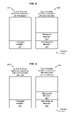
- FIG. 10 is a diagram describing a deadlock condition.
- a dashed arrow line shows dependency at the pointed direction. For example, if a first block has a dashed arrow line pointing to a second block, the first block depends on the second block and processing of the first block is queued/stalled after the second block.
- FIG. 10 describes interactions between an apparatus (e.g., a PCI Express device) and a root complex (e.g., a PCI Express end point for interfacing with a central processor).
- block 1010 describes transmitting a second read packet for reading from the root complex. Processing of block 1010 cannot complete until receiving, from the root complex, a completion packet in response to a first read packet previously transmitted from the apparatus to the root complex.
- block 1020 describes transmitting a write packet for writing to the apparatus. Processing of block 1020 cannot complete until receiving, from the apparatus, a completion packet in response to a read packet previously transmitted from the root complex to the apparatus.
- block 1030 describes transmitting the completion packet in response to the first read packet previously transmitted from the apparatus. However, processing of block 1030 is queued and stalled after transmitting the write packet (block 1020 ).
- block 1040 describes transmitting the completion packet in response to the read packet previously transmitted from the root complex. However, processing of block 1040 is queued and stalled after transmitting the second read packet (block 1010 ). As a result, a deadlock condition is formed as neither the apparatus nor the root complex can transmit a packet while being blocked waiting to receive a packet from each other.
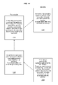
- FIG. 11 is a diagram describing the deadlock condition having been corrected in accordance with features and aspects hereof
- FIG. 11 is similar to FIG. 10 except that block 1140 is no longer stalled after being selected for processing after a period of time in accordance with features and aspects hereof.
- block 1020 may be processed after block 1140
- block 1030 may be processed after block 1020
- block 1010 may be processed after block 1030 so there is no longer a deadlock condition.
- the reason that processing cannot complete may be because there is insufficient credit of a FCCT.
- the reason that processing cannot complete may instead due to insufficient internal resources (e.g., insufficient buffer or memory space).
- features and aspects hereof may be applicable not just to improve processing of packets and packet descriptors in a credit-based flow control scheme, but also to avoid other problems including the potential deadlock condition including that described above.
Abstract
Description
Claims (19)
Priority Applications (1)
| Application Number | Priority Date | Filing Date | Title |
|---|---|---|---|
| US12/247,845 US8077620B2 (en) | 2008-10-08 | 2008-10-08 | Methods and apparatuses for processing packets in a credit-based flow control scheme |
Applications Claiming Priority (1)
| Application Number | Priority Date | Filing Date | Title |
|---|---|---|---|
| US12/247,845 US8077620B2 (en) | 2008-10-08 | 2008-10-08 | Methods and apparatuses for processing packets in a credit-based flow control scheme |
Publications (2)
| Publication Number | Publication Date |
|---|---|
| US20100085875A1 US20100085875A1 (en) | 2010-04-08 |
| US8077620B2 true US8077620B2 (en) | 2011-12-13 |
Family
ID=42075735
Family Applications (1)
| Application Number | Title | Priority Date | Filing Date |
|---|---|---|---|
| US12/247,845 Expired - Fee Related US8077620B2 (en) | 2008-10-08 | 2008-10-08 | Methods and apparatuses for processing packets in a credit-based flow control scheme |
Country Status (1)
| Country | Link |
|---|---|
| US (1) | US8077620B2 (en) |
Cited By (10)
| Publication number | Priority date | Publication date | Assignee | Title |
|---|---|---|---|---|
| US9313047B2 (en) | 2009-11-06 | 2016-04-12 | F5 Networks, Inc. | Handling high throughput and low latency network data packets in a traffic management device |
| US9606946B2 (en) | 2009-01-16 | 2017-03-28 | F5 Networks, Inc. | Methods for sharing bandwidth across a packetized bus and systems thereof |
| US9635024B2 (en) | 2013-12-16 | 2017-04-25 | F5 Networks, Inc. | Methods for facilitating improved user authentication using persistent data and devices thereof |
| US9864606B2 (en) | 2013-09-05 | 2018-01-09 | F5 Networks, Inc. | Methods for configurable hardware logic device reloading and devices thereof |
| US10015143B1 (en) | 2014-06-05 | 2018-07-03 | F5 Networks, Inc. | Methods for securing one or more license entitlement grants and devices thereof |
| US10135831B2 (en) | 2011-01-28 | 2018-11-20 | F5 Networks, Inc. | System and method for combining an access control system with a traffic management system |
| US10375155B1 (en) | 2013-02-19 | 2019-08-06 | F5 Networks, Inc. | System and method for achieving hardware acceleration for asymmetric flow connections |
| US10972453B1 (en) | 2017-05-03 | 2021-04-06 | F5 Networks, Inc. | Methods for token refreshment based on single sign-on (SSO) for federated identity environments and devices thereof |
| US11537716B1 (en) | 2018-11-13 | 2022-12-27 | F5, Inc. | Methods for detecting changes to a firmware and devices thereof |
| US11855898B1 (en) | 2018-03-14 | 2023-12-26 | F5, Inc. | Methods for traffic dependent direct memory access optimization and devices thereof |
Families Citing this family (6)
| Publication number | Priority date | Publication date | Assignee | Title |
|---|---|---|---|---|
| US8103837B2 (en) * | 2008-12-17 | 2012-01-24 | Hewlett-Packard Development Company, L.P. | Servicing memory read requests |
| US8112491B1 (en) | 2009-01-16 | 2012-02-07 | F5 Networks, Inc. | Methods and systems for providing direct DMA |
| US9152483B2 (en) | 2009-01-16 | 2015-10-06 | F5 Networks, Inc. | Network devices with multiple fully isolated and independently resettable direct memory access channels and methods thereof |
| US20100312928A1 (en) * | 2009-06-09 | 2010-12-09 | Brownell Paul V | System and method for operating a communication link |
| US9270602B1 (en) * | 2012-12-31 | 2016-02-23 | F5 Networks, Inc. | Transmit rate pacing of large network traffic bursts to reduce jitter, buffer overrun, wasted bandwidth, and retransmissions |
| CN105652737A (en) * | 2015-05-28 | 2016-06-08 | 宇龙计算机通信科技(深圳)有限公司 | Equipment control method, intelligent equipment, server and equipment control system |
Citations (5)
| Publication number | Priority date | Publication date | Assignee | Title |
|---|---|---|---|---|
| US5956340A (en) * | 1997-08-05 | 1999-09-21 | Ramot University Authority For Applied Research And Industrial Development Ltd. | Space efficient fair queuing by stochastic Memory multiplexing |
| US6781956B1 (en) * | 1999-09-17 | 2004-08-24 | Cisco Technology, Inc. | System and method for prioritizing packetized data from a distributed control environment for transmission through a high bandwidth link |
| US6829649B1 (en) * | 2000-11-10 | 2004-12-07 | International Business Machines Corporation | Method an congestion control system to allocate bandwidth of a link to dataflows |
| US7327682B2 (en) * | 2003-06-27 | 2008-02-05 | Cisco Technology, Inc. | Methods and devices for flexible bandwidth allocation |
| US20080107020A1 (en) * | 2006-11-03 | 2008-05-08 | Man Trinh | Highly-scalable hardware-based traffic management within a network processor integrated circuit |
Family Cites Families (1)
| Publication number | Priority date | Publication date | Assignee | Title |
|---|---|---|---|---|
| US7342936B2 (en) * | 2002-06-17 | 2008-03-11 | Integrated Device Technology, Inc. | Method of performing deficit round-robin scheduling and structure for implementing same |
-
2008
- 2008-10-08 US US12/247,845 patent/US8077620B2/en not_active Expired - Fee Related
Patent Citations (5)
| Publication number | Priority date | Publication date | Assignee | Title |
|---|---|---|---|---|
| US5956340A (en) * | 1997-08-05 | 1999-09-21 | Ramot University Authority For Applied Research And Industrial Development Ltd. | Space efficient fair queuing by stochastic Memory multiplexing |
| US6781956B1 (en) * | 1999-09-17 | 2004-08-24 | Cisco Technology, Inc. | System and method for prioritizing packetized data from a distributed control environment for transmission through a high bandwidth link |
| US6829649B1 (en) * | 2000-11-10 | 2004-12-07 | International Business Machines Corporation | Method an congestion control system to allocate bandwidth of a link to dataflows |
| US7327682B2 (en) * | 2003-06-27 | 2008-02-05 | Cisco Technology, Inc. | Methods and devices for flexible bandwidth allocation |
| US20080107020A1 (en) * | 2006-11-03 | 2008-05-08 | Man Trinh | Highly-scalable hardware-based traffic management within a network processor integrated circuit |
Cited By (10)
| Publication number | Priority date | Publication date | Assignee | Title |
|---|---|---|---|---|
| US9606946B2 (en) | 2009-01-16 | 2017-03-28 | F5 Networks, Inc. | Methods for sharing bandwidth across a packetized bus and systems thereof |
| US9313047B2 (en) | 2009-11-06 | 2016-04-12 | F5 Networks, Inc. | Handling high throughput and low latency network data packets in a traffic management device |
| US10135831B2 (en) | 2011-01-28 | 2018-11-20 | F5 Networks, Inc. | System and method for combining an access control system with a traffic management system |
| US10375155B1 (en) | 2013-02-19 | 2019-08-06 | F5 Networks, Inc. | System and method for achieving hardware acceleration for asymmetric flow connections |
| US9864606B2 (en) | 2013-09-05 | 2018-01-09 | F5 Networks, Inc. | Methods for configurable hardware logic device reloading and devices thereof |
| US9635024B2 (en) | 2013-12-16 | 2017-04-25 | F5 Networks, Inc. | Methods for facilitating improved user authentication using persistent data and devices thereof |
| US10015143B1 (en) | 2014-06-05 | 2018-07-03 | F5 Networks, Inc. | Methods for securing one or more license entitlement grants and devices thereof |
| US10972453B1 (en) | 2017-05-03 | 2021-04-06 | F5 Networks, Inc. | Methods for token refreshment based on single sign-on (SSO) for federated identity environments and devices thereof |
| US11855898B1 (en) | 2018-03-14 | 2023-12-26 | F5, Inc. | Methods for traffic dependent direct memory access optimization and devices thereof |
| US11537716B1 (en) | 2018-11-13 | 2022-12-27 | F5, Inc. | Methods for detecting changes to a firmware and devices thereof |
Also Published As
| Publication number | Publication date |
|---|---|
| US20100085875A1 (en) | 2010-04-08 |
Similar Documents
| Publication | Publication Date | Title |
|---|---|---|
| US8077620B2 (en) | Methods and apparatuses for processing packets in a credit-based flow control scheme | |
| US20220197838A1 (en) | System and method for facilitating efficient event notification management for a network interface controller (nic) | |
| US11934340B2 (en) | Multi-path RDMA transmission | |
| US20080049617A1 (en) | System for fine grained flow-control concurrency to prevent excessive packet loss | |
| US6747949B1 (en) | Register based remote data flow control | |
| KR101941416B1 (en) | Networking Technologies | |
| US7869356B2 (en) | Dynamic buffer pool in PCIExpress switches | |
| US7930437B2 (en) | Network adapter with shared database for message context information | |
| US8370552B2 (en) | Priority based bus arbiters avoiding deadlock and starvation on buses that support retrying of transactions | |
| US9459829B2 (en) | Low latency first-in-first-out (FIFO) buffer | |
| US8694701B2 (en) | Recovering dropped instructions in a network interface controller | |
| CN106506124B (en) | It retransmits message and determines method and device | |
| CN112559436B (en) | Context access method and system of RDMA communication equipment | |
| US10176126B1 (en) | Methods, systems, and computer program product for a PCI implementation handling multiple packets | |
| US11715337B2 (en) | Controller diagnostic device and method thereof | |
| US20090010157A1 (en) | Flow control in a variable latency system | |
| CN110083468A (en) | A kind of data transmission method, electronic device and storage medium | |
| US20120079145A1 (en) | Root hub virtual transaction translator | |
| CN100578479C (en) | Transmission control device and transmission control method | |
| US11165683B2 (en) | Network interface device | |
| US7373541B1 (en) | Alignment signal control apparatus and method for operating the same | |
| Chung et al. | Design and implementation of the high speed TCP/IP Offload Engine | |
| CN101097555B (en) | Method and system for processing data on chip | |
| CN113377277A (en) | Method, apparatus and computer program product for managing memory | |
| US11785087B1 (en) | Remote direct memory access operations with integrated data arrival indication |
Legal Events
| Date | Code | Title | Description |
|---|---|---|---|
| AS | Assignment |
Owner name: LSI CORPORATION,CALIFORNIA Free format text: ASSIGNMENT OF ASSIGNORS INTEREST;ASSIGNORS:SOLOMON, RICHARD;SAGHI, EUGENE;REEL/FRAME:021650/0412 Effective date: 20081007 Owner name: LSI CORPORATION, CALIFORNIA Free format text: ASSIGNMENT OF ASSIGNORS INTEREST;ASSIGNORS:SOLOMON, RICHARD;SAGHI, EUGENE;REEL/FRAME:021650/0412 Effective date: 20081007 |
|
| FEPP | Fee payment procedure |
Free format text: PAYOR NUMBER ASSIGNED (ORIGINAL EVENT CODE: ASPN); ENTITY STATUS OF PATENT OWNER: LARGE ENTITY |
|
| FEPP | Fee payment procedure |
Free format text: PAYOR NUMBER ASSIGNED (ORIGINAL EVENT CODE: ASPN); ENTITY STATUS OF PATENT OWNER: LARGE ENTITY Free format text: PAYER NUMBER DE-ASSIGNED (ORIGINAL EVENT CODE: RMPN); ENTITY STATUS OF PATENT OWNER: LARGE ENTITY |
|
| AS | Assignment |
Owner name: DEUTSCHE BANK AG NEW YORK BRANCH, AS COLLATERAL AG Free format text: PATENT SECURITY AGREEMENT;ASSIGNORS:LSI CORPORATION;AGERE SYSTEMS LLC;REEL/FRAME:032856/0031 Effective date: 20140506 |
|
| AS | Assignment |
Owner name: AVAGO TECHNOLOGIES GENERAL IP (SINGAPORE) PTE. LTD Free format text: ASSIGNMENT OF ASSIGNORS INTEREST;ASSIGNOR:LSI CORPORATION;REEL/FRAME:035390/0388 Effective date: 20140814 |
|
| REMI | Maintenance fee reminder mailed | ||
| LAPS | Lapse for failure to pay maintenance fees | ||
| STCH | Information on status: patent discontinuation |
Free format text: PATENT EXPIRED DUE TO NONPAYMENT OF MAINTENANCE FEES UNDER 37 CFR 1.362 |
|
| AS | Assignment |
Owner name: AGERE SYSTEMS LLC, PENNSYLVANIA Free format text: TERMINATION AND RELEASE OF SECURITY INTEREST IN PATENT RIGHTS (RELEASES RF 032856-0031);ASSIGNOR:DEUTSCHE BANK AG NEW YORK BRANCH, AS COLLATERAL AGENT;REEL/FRAME:037684/0039 Effective date: 20160201 Owner name: LSI CORPORATION, CALIFORNIA Free format text: TERMINATION AND RELEASE OF SECURITY INTEREST IN PATENT RIGHTS (RELEASES RF 032856-0031);ASSIGNOR:DEUTSCHE BANK AG NEW YORK BRANCH, AS COLLATERAL AGENT;REEL/FRAME:037684/0039 Effective date: 20160201 |
|
| FP | Lapsed due to failure to pay maintenance fee |
Effective date: 20151213 |