US7982269B2 - Transistors having asymmetric strained source/drain portions - Google Patents
Transistors having asymmetric strained source/drain portions Download PDFInfo
- Publication number
- US7982269B2 US7982269B2 US12/104,513 US10451308A US7982269B2 US 7982269 B2 US7982269 B2 US 7982269B2 US 10451308 A US10451308 A US 10451308A US 7982269 B2 US7982269 B2 US 7982269B2
- Authority
- US
- United States
- Prior art keywords
- region
- source
- physical contact
- direct physical
- regions
- Prior art date
- Legal status (The legal status is an assumption and is not a legal conclusion. Google has not performed a legal analysis and makes no representation as to the accuracy of the status listed.)
- Active, expires
Links
- 239000004065 semiconductor Substances 0.000 claims abstract description 21
- 239000000463 material Substances 0.000 claims abstract description 17
- 229910000577 Silicon-germanium Inorganic materials 0.000 claims description 55
- 125000001475 halogen functional group Chemical group 0.000 claims description 17
- 150000004767 nitrides Chemical class 0.000 claims description 17
- LEVVHYCKPQWKOP-UHFFFAOYSA-N [Si].[Ge] Chemical compound [Si].[Ge] LEVVHYCKPQWKOP-UHFFFAOYSA-N 0.000 claims description 3
- 125000006850 spacer group Chemical group 0.000 claims 4
- 239000000758 substrate Substances 0.000 description 19
- 238000000034 method Methods 0.000 description 17
- 238000005530 etching Methods 0.000 description 12
- 238000004519 manufacturing process Methods 0.000 description 12
- XUIMIQQOPSSXEZ-UHFFFAOYSA-N Silicon Chemical compound [Si] XUIMIQQOPSSXEZ-UHFFFAOYSA-N 0.000 description 11
- 229910052710 silicon Inorganic materials 0.000 description 11
- 239000010703 silicon Substances 0.000 description 11
- VYPSYNLAJGMNEJ-UHFFFAOYSA-N Silicium dioxide Chemical compound O=[Si]=O VYPSYNLAJGMNEJ-UHFFFAOYSA-N 0.000 description 8
- 229910052581 Si3N4 Inorganic materials 0.000 description 5
- HQVNEWCFYHHQES-UHFFFAOYSA-N silicon nitride Chemical compound N12[Si]34N5[Si]62N3[Si]51N64 HQVNEWCFYHHQES-UHFFFAOYSA-N 0.000 description 5
- 230000015572 biosynthetic process Effects 0.000 description 4
- 230000000903 blocking effect Effects 0.000 description 4
- 238000005755 formation reaction Methods 0.000 description 4
- 235000012239 silicon dioxide Nutrition 0.000 description 4
- 239000000377 silicon dioxide Substances 0.000 description 4
- OKTJSMMVPCPJKN-UHFFFAOYSA-N Carbon Chemical compound [C] OKTJSMMVPCPJKN-UHFFFAOYSA-N 0.000 description 3
- 229910052799 carbon Inorganic materials 0.000 description 3
- 229910052681 coesite Inorganic materials 0.000 description 3
- 229910052906 cristobalite Inorganic materials 0.000 description 3
- 238000001312 dry etching Methods 0.000 description 3
- 229910052682 stishovite Inorganic materials 0.000 description 3
- 229910052905 tridymite Inorganic materials 0.000 description 3
- 238000001039 wet etching Methods 0.000 description 3
- 238000007796 conventional method Methods 0.000 description 2
- 239000013078 crystal Substances 0.000 description 2
- 239000000203 mixture Substances 0.000 description 2
- 238000012986 modification Methods 0.000 description 2
- 230000004048 modification Effects 0.000 description 2
- 229910021420 polycrystalline silicon Inorganic materials 0.000 description 2
- 229920005591 polysilicon Polymers 0.000 description 2
- HMDDXIMCDZRSNE-UHFFFAOYSA-N [C].[Si] Chemical compound [C].[Si] HMDDXIMCDZRSNE-UHFFFAOYSA-N 0.000 description 1
- 150000001875 compounds Chemical class 0.000 description 1
- 239000002019 doping agent Substances 0.000 description 1
- 229910052732 germanium Inorganic materials 0.000 description 1
- GNPVGFCGXDBREM-UHFFFAOYSA-N germanium atom Chemical compound [Ge] GNPVGFCGXDBREM-UHFFFAOYSA-N 0.000 description 1
Images


Classifications
-
- H—ELECTRICITY
- H01—ELECTRIC ELEMENTS
- H01L—SEMICONDUCTOR DEVICES NOT COVERED BY CLASS H10
- H01L29/00—Semiconductor devices adapted for rectifying, amplifying, oscillating or switching, or capacitors or resistors with at least one potential-jump barrier or surface barrier, e.g. PN junction depletion layer or carrier concentration layer; Details of semiconductor bodies or of electrodes thereof ; Multistep manufacturing processes therefor
- H01L29/66—Types of semiconductor device ; Multistep manufacturing processes therefor
- H01L29/68—Types of semiconductor device ; Multistep manufacturing processes therefor controllable by only the electric current supplied, or only the electric potential applied, to an electrode which does not carry the current to be rectified, amplified or switched
- H01L29/76—Unipolar devices, e.g. field effect transistors
- H01L29/772—Field effect transistors
- H01L29/78—Field effect transistors with field effect produced by an insulated gate
- H01L29/785—Field effect transistors with field effect produced by an insulated gate having a channel with a horizontal current flow in a vertical sidewall of a semiconductor body, e.g. FinFET, MuGFET
-
- H—ELECTRICITY
- H01—ELECTRIC ELEMENTS
- H01L—SEMICONDUCTOR DEVICES NOT COVERED BY CLASS H10
- H01L29/00—Semiconductor devices adapted for rectifying, amplifying, oscillating or switching, or capacitors or resistors with at least one potential-jump barrier or surface barrier, e.g. PN junction depletion layer or carrier concentration layer; Details of semiconductor bodies or of electrodes thereof ; Multistep manufacturing processes therefor
- H01L29/66—Types of semiconductor device ; Multistep manufacturing processes therefor
- H01L29/66007—Multistep manufacturing processes
- H01L29/66075—Multistep manufacturing processes of devices having semiconductor bodies comprising group 14 or group 13/15 materials
- H01L29/66227—Multistep manufacturing processes of devices having semiconductor bodies comprising group 14 or group 13/15 materials the devices being controllable only by the electric current supplied or the electric potential applied, to an electrode which does not carry the current to be rectified, amplified or switched, e.g. three-terminal devices
- H01L29/66409—Unipolar field-effect transistors
- H01L29/66477—Unipolar field-effect transistors with an insulated gate, i.e. MISFET
- H01L29/66787—Unipolar field-effect transistors with an insulated gate, i.e. MISFET with a gate at the side of the channel
- H01L29/66795—Unipolar field-effect transistors with an insulated gate, i.e. MISFET with a gate at the side of the channel with a horizontal current flow in a vertical sidewall of a semiconductor body, e.g. FinFET, MuGFET
-
- H—ELECTRICITY
- H01—ELECTRIC ELEMENTS
- H01L—SEMICONDUCTOR DEVICES NOT COVERED BY CLASS H10
- H01L29/00—Semiconductor devices adapted for rectifying, amplifying, oscillating or switching, or capacitors or resistors with at least one potential-jump barrier or surface barrier, e.g. PN junction depletion layer or carrier concentration layer; Details of semiconductor bodies or of electrodes thereof ; Multistep manufacturing processes therefor
- H01L29/66—Types of semiconductor device ; Multistep manufacturing processes therefor
- H01L29/68—Types of semiconductor device ; Multistep manufacturing processes therefor controllable by only the electric current supplied, or only the electric potential applied, to an electrode which does not carry the current to be rectified, amplified or switched
- H01L29/76—Unipolar devices, e.g. field effect transistors
- H01L29/772—Field effect transistors
- H01L29/78—Field effect transistors with field effect produced by an insulated gate
- H01L29/7842—Field effect transistors with field effect produced by an insulated gate means for exerting mechanical stress on the crystal lattice of the channel region, e.g. using a flexible substrate
- H01L29/7848—Field effect transistors with field effect produced by an insulated gate means for exerting mechanical stress on the crystal lattice of the channel region, e.g. using a flexible substrate the means being located in the source/drain region, e.g. SiGe source and drain
Definitions
- the present invention relates to transistors, having asymmetrically strained source/drain portions.
- source/drain regions are usually etched, and then SiGe (silicon-germanium) or SiC (silicon-carbon) is epitaxially grown on source/drain portions of the fin region to provide strain into a channel region of the FET.
- SiGe silicon-germanium
- SiC silicon-carbon
- the present invention provides a semiconductor structure, comprising (a) a fin region, wherein the fin region includes (i) a first source/drain portion having a first surface and a third surface, wherein the first and third surfaces are (A) parallel to each other and (B) not coplanar, (ii) a second source/drain portion having a second surface and a fourth surface, wherein the second and fourth surfaces are (A) parallel to each other and (B) not coplanar, and (iii) a channel region disposed between the first and second source/drain portions; (b) a gate dielectric layer in direct physical contact with the channel region; (c) a gate electrode region in direct physical contact with the gate dielectric layer, wherein the gate dielectric layer (i) is sandwiched between, and (ii) electrically insulates the gate electrode region and the channel region; and (d) a first semiconductor strain creating region and a second semiconductor strain creating region on the third and fourth surfaces, respectively, wherein the first and second semiconductor strain creating regions comprise
- the present invention provides a transistor structure in which the channel region has higher strain than that of the prior art.
- FIGS. 1 A- 1 Eb illustrate a fabrication process for forming a vertical transistor (FinFET) structure, in accordance with embodiments of the present invention.
- FIGS. 2 A- 2 Db cross-section and top-down views
- FinFET vertical transistor
- FIGS. 3A-3E cross-section views illustrate a fabrication process for forming a planar transistor structure, in accordance with embodiments of the present invention.
- FIGS. 4A-4D cross-section views illustrate another fabrication process for forming another planar transistor structure, in accordance with embodiments of the present invention.
- FIGS. 1 A- 1 Eb illustrate a fabrication process for forming a vertical transistor (FinFET) structure 100 , in accordance with embodiments of the present invention. More specifically, with reference to FIG. 1A , the fabrication of the vertical transistor structure 100 starts out with a structure including (i) a silicon (Si) substrate 110 , (ii) a BOX (Buried Oxide) layer 120 on top of the Si substrate 110 , (iii) a fin region 130 (comprising silicon in one embodiment) on top of the BOX layer 120 , (iv) a hard mask 140 (comprising silicon nitride in one embodiment) on top of the fin region 130 , (v) a gate electrode region 150 (comprising polysilicon in one embodiment) on top of the hard mask 140 and the BOX layer 120 , (vi) a dielectric cap region 151 (comprising SiO2 in one embodiment) on top of the gate electrode region 150 , and (vii) nitride
- a patterned dielectric (e.g., silicon nitride, etc.) covering layer 170 is formed on top of the structure 100 of FIG. 1A . More specifically, the patterned nitride covering layer 170 is formed by using conventional lithographic and etching processes.
- the fin region 130 is etched with the patterned nitride covering layer 170 , the hard mask 140 , and the nitride spacers 160 a and 160 b serving as a blocking mask.
- the etching of the fin region 130 is performed essentially without affecting the BOX layer 120 .
- the fin region 130 of FIG. 1B is reduced to a fin region 132 of FIG. 1C .
- exposed surfaces of the fin region 130 are moved in a direction 133 .
- the etching of the fin region 130 can be isotropic.
- SiGe (silicon-germanium) material can be epitaxially grown on exposed silicon surfaces of the structure 100 of FIG. 1C , resulting in SiGe regions 180 a and 180 b of FIG. 1D .
- FIG. 1 Ea shows a cross-section view of the vertical transistor structure 100 of FIG. 1D along a plane defined by a line 1 Ea, in accordance with embodiments of the present invention.
- the vertical transistor structure 100 comprises gate dielectric layers 132 a and 132 b between the gate electrode region 150 and the fin region 132 , extension regions 192 a and 192 b implanted in the fin region 132 , halo regions 194 a and 194 b implanted in the fin region 132 , and a channel region 196 between the two extension regions 192 a and 192 b .
- the gate dielectric layers 132 a and 132 b , the extension regions 192 a and 192 b , the halo regions 194 a and 194 b , and the channel region 196 are already present in the structure 100 of FIGS. 1A-1D but these layer and regions were not shown or mentioned above with reference to FIGS. 1A-1D for simplicity.
- the SiGe regions 180 a and 180 b are on the same side of the fin region 132 .
- the extension regions 192 a and 192 b and the halo regions 194 a and 194 b are formed early and are present even in FIG. 1A (though not shown in FIG. 1A for simplicity).
- the extension regions 192 a and 192 b and the halo regions 194 a and 194 b can be formed after the formation of the SiGe regions 180 a and 180 b ( FIG. 1D ).
- the SiGe regions 180 a and 180 b will be parts of source/drain regions, which comprise source/drain portions 134 a and 134 b , respectively, of the fin region 132 of the vertical transistor structure 100 .
- the presence of the SiGe regions 180 a and 180 b (also called strain creating regions 180 a and 180 b ) in the vertical transistor structure 100 creates strain in the channel region 196 of the vertical transistor structure 100 . As a result, the strain in the channel region of the vertical transistor structure 100 is improved.
- this strain in the channel region 196 is created because the crystal lattice of the material of the strain creating regions 180 a and 180 b (i.e., SiGe) does not match the crystal lattice of the material of the channel region 196 (i.e., Si).
- the strain creating regions 180 a and 180 b can comprise SiC (mixture of silicon and carbon) for an NFET transistor.
- FIG. 1 Eb shows a cross-section view of a vertical transistor structure 100 ′, in accordance with embodiments of the present invention.
- the vertical transistor structure 100 ′ is similar to the vertical transistor structure 100 in FIG. 1 Ea, except that SiGe regions 180 a ′ and 180 b ′ are on opposite sides of the fin region 132 .
- the patterned nitride covering layer 170 (similar to the patterned nitride covering layer 170 in FIG. 1C ) is formed in two opposite sides, and the step of etching the fin region 130 (similar to the etching step to form the structure of FIG.
- FIG. 1C is performed such that exposed surfaces of the fin region 130 are moved in two opposite directions.
- a gate dielectric layer, extension regions, halo regions, and a channel region of the vertical transistor structure 100 ′ are omitted in FIG. 1 Eb for simplicity.
- the presence of the SiGe regions 180 a ′ and 180 b ′ in the vertical transistor structure 100 ′ improves the strain in the channel region of the vertical transistor structure 100 ′ and thereby improves the operation of the vertical transistor structure 100 ′.
- FIGS. 2 A- 2 Db cross-section views
- FIGS. 2 A- 2 Db cross-section views
- FIGS. 2 A- 2 Db illustrate a fabrication process for forming a vertical transistor (FinFET) structure 200 , in accordance with embodiments of the present invention. More specifically, the fabrication process starts out with a structure which is similar to the structure 100 of FIG. 1C .
- FIG. 2A shows a cross-section view of the vertical transistor structure 100 of FIG. 1C along a plane defined by a line 2 A.
- similar regions of the structure 200 of FIG. 2A and the structure 100 of FIG. 1C have the same reference numerals, except for the first digit, which is used to indicate the figure number.
- a patterned dielectric (e.g., silicon nitride) covering layer 270 ( FIG. 2A ) and the patterned nitride covering layer 170 ( FIG. 1C ) are similar.
- the patterned nitride covering layer 270 is removed by an etching step which is essentially selective to a hard mask 240 , a fin region 232 , and a BOX layer 220 , resulting in the structure 200 of FIG. 2B .
- the removal of the patterned nitride covering layer 270 can be achieved by an isotropic etch such as a wet etch or a plasma etch.
- SiGe material can be epitaxially grown on exposed silicon surfaces of the structure 200 of FIG. 2B , resulting in SiGe regions 280 c and 280 d of FIG. 2C .
- FIG. 2 Da shows a top-down view of structure 200 of FIG. 2C , in accordance with embodiments of the present invention.
- SiGe regions 280 c , 280 d , 280 c ′, and 280 d ′, the fin region 232 , the BOX layer 220 are shown in FIG. 2 Da.
- the formations of SiGe regions 280 c ′ and 280 d ′ are similar to the formations of the SiGe regions 280 c and 280 d .
- the fin region 232 was recessed at two places on one side (left side) of the fin region 232 .
- the SiGe regions 280 c , 280 d , 280 c ′, and 280 d ′ will be parts of source/drain regions of the vertical transistor structure 200 .
- the presence of the SiGe regions 280 c and 280 c ′ in the vertical transistor structure 200 creates strain in the channel region of the vertical transistor structure 200 .
- the strain in the channel region of the vertical transistor structure 200 is improved thereby improving the operation of the vertical transistor structure 200 .
- FIG. 2 Db shows a top-down view of a vertical transistor structure 200 ′, in accordance with alternative embodiments of the present invention.
- the vertical transistor structure 200 ′ is similar to the vertical transistor structure 200 of FIG. 2 Da, except that the fin region 232 was recessed at two places on opposite sides of the fin region 232 .
- the SiGe regions 280 c , 280 c ′, 280 d , and 280 d ′ (also called expansion regions 280 c , 280 c ′, 280 d , and 280 d ′) will be parts of source/drain regions of the vertical transistor structure 200 ′.
- the source/drain regions of the vertical transistor structure 200 ′ comprise source/drain portions 234 a and 234 b of the fin region 232 of the vertical transistor structure 200 ′.
- the source/drain portion 234 a has surfaces 281 and 282 on which the SiGe regions 280 c and 280 d reside, respectively.
- the source/drain portion 234 b has surfaces 281 ′ and 282 ′ on which the SiGe regions 280 c ′ and 280 d ′ reside, respectively.
- the surface 281 is not coplanar with surface 282 ′.
- the surface 282 is not coplanar with either the surface 281 ′ or the surface 282 ′.
- the presence of the SiGe regions 280 c and 280 c ′ in the vertical transistor structure 200 ′ creates strain in the channel region of the vertical transistor structure 200 ′.
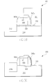
- FIGS. 3A-3E illustrate a fabrication process for forming a planar transistor structure 300 , in accordance with embodiments of the present invention. More specifically, with reference to FIG. 3A , the fabrication of the planar transistor structure 300 starts out with a structure including (i) a silicon substrate 310 , (ii) a gate dielectric layer 320 (comprising silicon dioxide in one embodiment) on top of the Si substrate 310 , (iii) a gate electrode region 330 (comprising polysilicon in one embodiment) on top of the gate dielectric layer 320 , (iv) a dielectric cap region 331 (comprising SiO2 in one embodiment) on top of the gate electrode region 330 , (v) nitride spacers 340 a and 340 b (comprising silicon nitride in one embodiment) on side walls of the gate electrode region 330 and the dielectric cap region 331 , and (vi) a dielectric covering layer 332 (compris
- a patterned photo-resist layer 311 is formed on top of the Si substrate 310 .
- the patterned photo-resist layer 311 is formed by using a conventional lithographic process.
- portions of the dielectric covering layer 332 not covered by the patterned photo-resist layer 311 are removed by a wet etching process.
- the Si substrate 310 is etched with the patterned photo-resist layer 311 , the dielectric cap region 331 , and the nitride spacers 340 a and 340 b serving as a blocking mask, resulting in a trench 312 in the Si substrate 310 .
- the etching of the Si substrate 310 can be dry etching.
- the trench 312 is formed aligned with the nitride spacer 340 a .
- the gate electrode region 330 is not etched because the gate electrode region 330 is protected by the dielectric cap region 331 .
- the patterned photo-resist layer 311 can be removed using a wet etching process.
- SiGe material can be epitaxially grown on exposed silicon surface of the trench 312 of FIG. 3B , resulting in a SiGe region 350 a of FIG. 3C . It should be noted that SiGe material does not grow on the right side of the gate electrode region 330 because the Si substrate 310 on this right side is still covered/protected by the dielectric covering layer 332 .
- FIG. 3C is modified to form FIG. 3D . More specifically, with reference to FIG. 3D , a patterned photo-resist layer 313 is formed on top of the SiGe region 350 a . In one embodiment, the patterned photo-resist layer 313 is formed by using a conventional lithographic process.
- the remaining portions of the dielectric covering layer 332 are removed.
- the Si substrate 310 is etched with the patterned photo-resist layer 313 , the dielectric cap region 331 , and the nitride spacers 340 a and 340 b serving as a blocking mask, resulting in a trench 314 in the Si substrate 310 .
- the etching of the Si substrate 310 can be dry etching.
- the trench 314 is formed aligned with the nitride spacer 340 b . It should be noted that during the etching of the Si substrate 310 , the gate electrode region 330 is not etched because the gate electrode region 330 is protected by the dielectric cap region 331 .
- the patterned photo-resist layer 313 can be removed using a wet etching process.
- SiGe material can be epitaxially grown on exposed silicon surface of the trench 314 of FIG. 3D , resulting in SiGe regions 350 a ′ and 350 b of FIG. 3E .
- a thickness 352 of the SiGe region 350 a + 350 a ′ is greater than a thickness 354 of the SiGe region 350 b .
- SiGe material also grows on the SiGe region 350 a (on the left) resulting in the SiGe region 350 a′.
- the planar transistor structure 300 comprises extension regions 312 a and 312 b implanted in the Si substrate 310 , halo regions 314 a and 314 b implanted in the Si substrate 310 , and a channel region 316 between the two extension regions 312 a and 312 b .
- the extension regions 312 a and 312 b , the halo regions 314 a and 314 b , and the channel region 316 may already be present in the structure 300 of FIGS. 3A-3D (in one embodiment) but these layer and regions are not shown or mentioned above with reference to FIGS. 3A-3D for simplicity.
- the SiGe regions 350 a + 350 a ′ and 350 b will be parts of source/drain regions of the planar transistor structure 300 .
- the presence of the SiGe source/drain regions 350 a + 350 a ′ and 350 b in the planar transistor structure 300 creates strain in the channel region 316 of the planar transistor structure 300 . As a result, the operation of the planar transistor structure 300 is improved.
- the source/drain regions 350 a + 350 a ′ and 350 b comprise SiGe.
- one of the source/drain regions 350 a + 350 a ′ and 350 b comprises Si, whereas the other of the source/drain regions 350 a + 350 a ′ and 350 b comprises SiGe.
- FIGS. 4A-4D cross-section views illustrate a fabrication process for forming a planar transistor structure 400 , in accordance with embodiments of the present invention. More specifically, the fabrication process starts out with the structure 400 of FIG. 4A .
- the structure 400 of FIG. 4A is similar to the structure 300 of FIG. 3A (without the dielectric covering layer 332 ).
- similar regions of the structure 400 of FIG. 4A and the structure 300 of FIG. 3A have the same reference numerals, except for the first digit, which is used to indicate the figure number.
- a gate dielectric layer 420 ( FIG. 4A ) and the gate dielectric layer 320 ( FIG. 3A ) are similar.
- an extra nitride spacer 450 is formed on side wall of a nitride spacer 440 b .
- the extra nitride spacer 450 is formed by using a conventional process.
- the Si substrate 410 is etched with the extra nitride spacer 450 , the nitride spacers 440 a and 440 b , and the dielectric cap region 431 serving as a blocking mask resulting in trenches 412 and 414 in the Si substrate 410 .
- the etching of the Si substrate 410 can be dry etching.
- the trenches 412 and 414 are formed aligned with the nitride spacer 440 a and the extra nitride spacer 450 , respectively.
- SiGe material can be epitaxially grown on exposed silicon surface of the trenches 412 and 414 of FIG. 4C , resulting in SiGe regions 460 a and 460 b , respectively, of FIG. 4D . It should be noted that thicknesses 462 and 464 of the SiGe regions 460 a and 460 b , respectively, are the same.
- the SiGe regions 460 a and 460 b will be parts of source/drain regions of the planar transistor structure 400 .
- the presence of the SiGe source/drain regions 460 a and 460 b in the planar transistor structure 400 creates strain in channel region 422 of the planar transistor structure 400 . As a result, the operation of the planar transistor structure 400 is improved.
- the source/drain regions 460 a and 460 b comprise SiGe.
- one of the source/drain regions 460 a and 460 b comprises Si, whereas the other of the source/drain regions 460 a and 460 b comprises SiGe.
- SiGe material is used.
- compound semiconductors including silicon, carbon, germanium, etc are used.
- the SiGe regions will later be doped with dopants so that they can serve as parts of the source/drain regions of the transistors.
- SiGe is epitaxially grown resulting the regions 180 a and 180 b ( FIG. 1D ), regions 280 c and 280 d ( FIG. 2C ), region 350 a ( FIG. 3C ), regions 350 a ′ and 350 b ( FIG. 3E ), and regions 460 a and 460 b ( FIG. 4D ).
- any other strain-creating material can be used provided that the resulting regions create strain in the corresponding channel regions.
- SiC a mixture of silicon and carbon
- SiGe can be used instead of SiGe to create optimal strain if the structure is to be an NFET.
Abstract
Description
Claims (9)
Priority Applications (1)
| Application Number | Priority Date | Filing Date | Title |
|---|---|---|---|
| US12/104,513 US7982269B2 (en) | 2008-04-17 | 2008-04-17 | Transistors having asymmetric strained source/drain portions |
Applications Claiming Priority (1)
| Application Number | Priority Date | Filing Date | Title |
|---|---|---|---|
| US12/104,513 US7982269B2 (en) | 2008-04-17 | 2008-04-17 | Transistors having asymmetric strained source/drain portions |
Publications (2)
| Publication Number | Publication Date |
|---|---|
| US20090261380A1 US20090261380A1 (en) | 2009-10-22 |
| US7982269B2 true US7982269B2 (en) | 2011-07-19 |
Family
ID=41200381
Family Applications (1)
| Application Number | Title | Priority Date | Filing Date |
|---|---|---|---|
| US12/104,513 Active 2029-10-25 US7982269B2 (en) | 2008-04-17 | 2008-04-17 | Transistors having asymmetric strained source/drain portions |
Country Status (1)
| Country | Link |
|---|---|
| US (1) | US7982269B2 (en) |
Cited By (4)
| Publication number | Priority date | Publication date | Assignee | Title |
|---|---|---|---|---|
| US20110198673A1 (en) * | 2010-02-17 | 2011-08-18 | Globalfoundries Inc. | Formation of finfet gate spacer |
| US9299711B2 (en) | 2012-09-26 | 2016-03-29 | Samsung Electronics Co., Ltd. | Field effect transistors including asymmetrical silicide structures and related devices |
| US9691902B2 (en) | 2015-04-30 | 2017-06-27 | Samsung Electronics Co., Ltd. | Semiconductor device |
| US10269944B2 (en) * | 2015-06-30 | 2019-04-23 | Taiwan Semiconductor Manufacturing Company, Ltd. | Fin semiconductor device and method of manufacture with source/drain regions having opposite conductivities |
Families Citing this family (4)
| Publication number | Priority date | Publication date | Assignee | Title |
|---|---|---|---|---|
| US7982269B2 (en) * | 2008-04-17 | 2011-07-19 | International Business Machines Corporation | Transistors having asymmetric strained source/drain portions |
| US9812336B2 (en) * | 2013-10-29 | 2017-11-07 | Globalfoundries Inc. | FinFET semiconductor structures and methods of fabricating same |
| US9246005B2 (en) | 2014-02-12 | 2016-01-26 | International Business Machines Corporation | Stressed channel bulk fin field effect transistor |
| US9755073B1 (en) | 2016-05-11 | 2017-09-05 | International Business Machines Corporation | Fabrication of vertical field effect transistor structure with strained channels |
Citations (24)
| Publication number | Priority date | Publication date | Assignee | Title |
|---|---|---|---|---|
| US6492216B1 (en) | 2002-02-07 | 2002-12-10 | Taiwan Semiconductor Manufacturing Company | Method of forming a transistor with a strained channel |
| US6638802B1 (en) | 2002-06-20 | 2003-10-28 | Intel Corporation | Forming strained source drain junction field effect transistors |
| US20040169239A1 (en) * | 2003-02-28 | 2004-09-02 | Kern Rim | Multiple gate MOSFET structure with strained Si Fin body |
| US6794718B2 (en) * | 2002-12-19 | 2004-09-21 | International Business Machines Corporation | High mobility crystalline planes in double-gate CMOS technology |
| US6885084B2 (en) | 2001-11-01 | 2005-04-26 | Intel Corporation | Semiconductor transistor having a stressed channel |
| US6888181B1 (en) * | 2004-03-18 | 2005-05-03 | United Microelectronics Corp. | Triple gate device having strained-silicon channel |
| US6960806B2 (en) * | 2001-06-21 | 2005-11-01 | International Business Machines Corporation | Double gated vertical transistor with different first and second gate materials |
| US20060022253A1 (en) * | 2004-07-28 | 2006-02-02 | International Business Machines Corporation | Multiple-gate device with floating back gate |
| US6998684B2 (en) * | 2004-03-31 | 2006-02-14 | International Business Machines Corporation | High mobility plane CMOS SOI |
| US20060043592A1 (en) | 2004-08-31 | 2006-03-02 | Seiko Epson Corporation | Substlate, electro-optical device, electronic apparatus, method of forming substlate, method of forming electro-optical device, and method of forming electronic apparatus |
| US20060076625A1 (en) | 2004-09-25 | 2006-04-13 | Lee Sung-Young | Field effect transistors having a strained silicon channel and methods of fabricating same |
| US7102205B2 (en) | 2004-09-01 | 2006-09-05 | International Business Machines Corporation | Bipolar transistor with extrinsic stress layer |
| US7115920B2 (en) * | 2004-04-12 | 2006-10-03 | International Business Machines Corporation | FinFET transistor and circuit |
| US7183142B2 (en) * | 2005-01-13 | 2007-02-27 | International Business Machines Corporation | FinFETs with long gate length at high density |
| US7355253B2 (en) * | 2003-08-22 | 2008-04-08 | International Business Machines Corporation | Strained-channel Fin field effect transistor (FET) with a uniform channel thickness and separate gates |
| US7449373B2 (en) * | 2006-03-31 | 2008-11-11 | Intel Corporation | Method of ion implanting for tri-gate devices |
| US7456476B2 (en) * | 2003-06-27 | 2008-11-25 | Intel Corporation | Nonplanar semiconductor device with partially or fully wrapped around gate electrode and methods of fabrication |
| US7510916B2 (en) * | 2003-05-01 | 2009-03-31 | International Business Machines Corporation | High performance FET devices and methods thereof |
| US20090263949A1 (en) * | 2008-04-17 | 2009-10-22 | Brent Alan Anderson | Transistors having asymmetric strained source/drain portions |
| US20090261380A1 (en) * | 2008-04-17 | 2009-10-22 | Brent Alan Anderson | Transistors having asymetric strained source/drain portions |
| US20090302402A1 (en) * | 2008-06-04 | 2009-12-10 | Anderson Brent A | Mugfet with stub source and drain regions |
| US7718489B2 (en) * | 2005-05-18 | 2010-05-18 | International Business Machines Corporation | Double-gate FETs (field effect transistors) |
| US7781771B2 (en) * | 2004-03-31 | 2010-08-24 | Intel Corporation | Bulk non-planar transistor having strained enhanced mobility and methods of fabrication |
| US7799592B2 (en) * | 2006-09-27 | 2010-09-21 | Taiwan Semiconductor Manufacturing Company, Ltd. | Tri-gate field-effect transistors formed by aspect ratio trapping |
-
2008
- 2008-04-17 US US12/104,513 patent/US7982269B2/en active Active
Patent Citations (32)
| Publication number | Priority date | Publication date | Assignee | Title |
|---|---|---|---|---|
| US6960806B2 (en) * | 2001-06-21 | 2005-11-01 | International Business Machines Corporation | Double gated vertical transistor with different first and second gate materials |
| US6885084B2 (en) | 2001-11-01 | 2005-04-26 | Intel Corporation | Semiconductor transistor having a stressed channel |
| US6492216B1 (en) | 2002-02-07 | 2002-12-10 | Taiwan Semiconductor Manufacturing Company | Method of forming a transistor with a strained channel |
| US6638802B1 (en) | 2002-06-20 | 2003-10-28 | Intel Corporation | Forming strained source drain junction field effect transistors |
| US6794718B2 (en) * | 2002-12-19 | 2004-09-21 | International Business Machines Corporation | High mobility crystalline planes in double-gate CMOS technology |
| US20040169239A1 (en) * | 2003-02-28 | 2004-09-02 | Kern Rim | Multiple gate MOSFET structure with strained Si Fin body |
| US6815738B2 (en) * | 2003-02-28 | 2004-11-09 | International Business Machines Corporation | Multiple gate MOSFET structure with strained Si Fin body |
| US7510916B2 (en) * | 2003-05-01 | 2009-03-31 | International Business Machines Corporation | High performance FET devices and methods thereof |
| US7820513B2 (en) * | 2003-06-27 | 2010-10-26 | Intel Corporation | Nonplanar semiconductor device with partially or fully wrapped around gate electrode and methods of fabrication |
| US7456476B2 (en) * | 2003-06-27 | 2008-11-25 | Intel Corporation | Nonplanar semiconductor device with partially or fully wrapped around gate electrode and methods of fabrication |
| US7355253B2 (en) * | 2003-08-22 | 2008-04-08 | International Business Machines Corporation | Strained-channel Fin field effect transistor (FET) with a uniform channel thickness and separate gates |
| US7384830B2 (en) * | 2003-08-22 | 2008-06-10 | International Business Machines Corporation | Strained-channel Fin field effect transistor (FET) with a uniform channel thickness and separate gates |
| US6888181B1 (en) * | 2004-03-18 | 2005-05-03 | United Microelectronics Corp. | Triple gate device having strained-silicon channel |
| US6998684B2 (en) * | 2004-03-31 | 2006-02-14 | International Business Machines Corporation | High mobility plane CMOS SOI |
| US7781771B2 (en) * | 2004-03-31 | 2010-08-24 | Intel Corporation | Bulk non-planar transistor having strained enhanced mobility and methods of fabrication |
| US20060076623A1 (en) * | 2004-03-31 | 2006-04-13 | Anderson Brent A | High mobility plane CMOS SOI |
| US7439109B2 (en) * | 2004-03-31 | 2008-10-21 | International Business Machines Corporation | Method of forming an integrated circuit structure on a hybrid crystal oriented substrate |
| US7115920B2 (en) * | 2004-04-12 | 2006-10-03 | International Business Machines Corporation | FinFET transistor and circuit |
| US7259420B2 (en) * | 2004-07-28 | 2007-08-21 | International Business Machines Corporation | Multiple-gate device with floating back gate |
| US20070212834A1 (en) * | 2004-07-28 | 2007-09-13 | Anderson Brent A | Multiple-gate device with floating back gate |
| US20060022253A1 (en) * | 2004-07-28 | 2006-02-02 | International Business Machines Corporation | Multiple-gate device with floating back gate |
| US20060043592A1 (en) | 2004-08-31 | 2006-03-02 | Seiko Epson Corporation | Substlate, electro-optical device, electronic apparatus, method of forming substlate, method of forming electro-optical device, and method of forming electronic apparatus |
| US7102205B2 (en) | 2004-09-01 | 2006-09-05 | International Business Machines Corporation | Bipolar transistor with extrinsic stress layer |
| US20060076625A1 (en) | 2004-09-25 | 2006-04-13 | Lee Sung-Young | Field effect transistors having a strained silicon channel and methods of fabricating same |
| US7183142B2 (en) * | 2005-01-13 | 2007-02-27 | International Business Machines Corporation | FinFETs with long gate length at high density |
| US7718489B2 (en) * | 2005-05-18 | 2010-05-18 | International Business Machines Corporation | Double-gate FETs (field effect transistors) |
| US7449373B2 (en) * | 2006-03-31 | 2008-11-11 | Intel Corporation | Method of ion implanting for tri-gate devices |
| US7799592B2 (en) * | 2006-09-27 | 2010-09-21 | Taiwan Semiconductor Manufacturing Company, Ltd. | Tri-gate field-effect transistors formed by aspect ratio trapping |
| US20090263949A1 (en) * | 2008-04-17 | 2009-10-22 | Brent Alan Anderson | Transistors having asymmetric strained source/drain portions |
| US20090261380A1 (en) * | 2008-04-17 | 2009-10-22 | Brent Alan Anderson | Transistors having asymetric strained source/drain portions |
| US20090302402A1 (en) * | 2008-06-04 | 2009-12-10 | Anderson Brent A | Mugfet with stub source and drain regions |
| US7902000B2 (en) * | 2008-06-04 | 2011-03-08 | International Business Machines Corporation | MugFET with stub source and drain regions |
Cited By (6)
| Publication number | Priority date | Publication date | Assignee | Title |
|---|---|---|---|---|
| US20110198673A1 (en) * | 2010-02-17 | 2011-08-18 | Globalfoundries Inc. | Formation of finfet gate spacer |
| US8174055B2 (en) * | 2010-02-17 | 2012-05-08 | Globalfoundries Inc. | Formation of FinFET gate spacer |
| US8525234B2 (en) | 2010-02-17 | 2013-09-03 | Globalfoundries Inc. | Formation of FinFET gate spacer |
| US9299711B2 (en) | 2012-09-26 | 2016-03-29 | Samsung Electronics Co., Ltd. | Field effect transistors including asymmetrical silicide structures and related devices |
| US9691902B2 (en) | 2015-04-30 | 2017-06-27 | Samsung Electronics Co., Ltd. | Semiconductor device |
| US10269944B2 (en) * | 2015-06-30 | 2019-04-23 | Taiwan Semiconductor Manufacturing Company, Ltd. | Fin semiconductor device and method of manufacture with source/drain regions having opposite conductivities |
Also Published As
| Publication number | Publication date |
|---|---|
| US20090261380A1 (en) | 2009-10-22 |
Similar Documents
| Publication | Publication Date | Title |
|---|---|---|
| US7964465B2 (en) | Transistors having asymmetric strained source/drain portions | |
| US9711412B2 (en) | FinFETs with different fin heights | |
| US7781771B2 (en) | Bulk non-planar transistor having strained enhanced mobility and methods of fabrication | |
| US10032910B2 (en) | FinFET devices having asymmetrical epitaxially-grown source and drain regions and methods of forming the same | |
| US8748993B2 (en) | FinFETs with multiple fin heights | |
| US9257344B2 (en) | FinFETs with different fin height and EPI height setting | |
| US7977174B2 (en) | FinFET structures with stress-inducing source/drain-forming spacers and methods for fabricating the same | |
| US8648400B2 (en) | FinFET semiconductor device with germanium (GE) fins | |
| JP4378293B2 (en) | Structure and method for forming strained SiMOSFETs | |
| JP4439486B2 (en) | Semiconductor device | |
| US7982269B2 (en) | Transistors having asymmetric strained source/drain portions | |
| US20070221956A1 (en) | Semiconductor device and method of fabricating the same | |
| EP3312876A1 (en) | Finfet device and fabrication method thereof | |
| JP2006093717A (en) | Field-effect transistor having transformed channel layer and method of manufacturing the same | |
| US8518757B2 (en) | Method of fabricating strained semiconductor structures from silicon-on-insulator (SOI) | |
| WO2012027864A1 (en) | Semiconductor structure and method for manufacturing the same | |
| US20060121687A1 (en) | Semiconductor device having a multi-bridge-channel and method for fabricating the same | |
| WO2014063404A1 (en) | Semiconductor structure and manufacturing method thereof | |
| US20060108651A1 (en) | Lowered Source/Drain Transistors |
Legal Events
| Date | Code | Title | Description |
|---|---|---|---|
| AS | Assignment |
Owner name: INTERNATIONAL BUSINESS MACHINES CORPORATION, NEW Y Free format text: ASSIGNMENT OF ASSIGNORS INTEREST;ASSIGNORS:ANDERSON, BRENT A.;BRYANT, ANDRES;NOWAK, EDWARD J.;REEL/FRAME:020815/0385;SIGNING DATES FROM 20080410 TO 20080411 Owner name: INTERNATIONAL BUSINESS MACHINES CORPORATION, NEW Y Free format text: ASSIGNMENT OF ASSIGNORS INTEREST;ASSIGNORS:ANDERSON, BRENT A.;BRYANT, ANDRES;NOWAK, EDWARD J.;SIGNING DATES FROM 20080410 TO 20080411;REEL/FRAME:020815/0385 |
|
| STCF | Information on status: patent grant |
Free format text: PATENTED CASE |
|
| FPAY | Fee payment |
Year of fee payment: 4 |
|
| AS | Assignment |
Owner name: GLOBALFOUNDRIES U.S. 2 LLC, NEW YORK Free format text: ASSIGNMENT OF ASSIGNORS INTEREST;ASSIGNOR:INTERNATIONAL BUSINESS MACHINES CORPORATION;REEL/FRAME:036550/0001 Effective date: 20150629 |
|
| AS | Assignment |
Owner name: GLOBALFOUNDRIES INC., CAYMAN ISLANDS Free format text: ASSIGNMENT OF ASSIGNORS INTEREST;ASSIGNORS:GLOBALFOUNDRIES U.S. 2 LLC;GLOBALFOUNDRIES U.S. INC.;REEL/FRAME:036779/0001 Effective date: 20150910 |
|
| AS | Assignment |
Owner name: WILMINGTON TRUST, NATIONAL ASSOCIATION, DELAWARE Free format text: SECURITY AGREEMENT;ASSIGNOR:GLOBALFOUNDRIES INC.;REEL/FRAME:049490/0001 Effective date: 20181127 |
|
| MAFP | Maintenance fee payment |
Free format text: PAYMENT OF MAINTENANCE FEE, 8TH YEAR, LARGE ENTITY (ORIGINAL EVENT CODE: M1552); ENTITY STATUS OF PATENT OWNER: LARGE ENTITY Year of fee payment: 8 |
|
| AS | Assignment |
Owner name: GLOBALFOUNDRIES U.S. INC., CALIFORNIA Free format text: ASSIGNMENT OF ASSIGNORS INTEREST;ASSIGNOR:GLOBALFOUNDRIES INC.;REEL/FRAME:054633/0001 Effective date: 20201022 |
|
| AS | Assignment |
Owner name: GLOBALFOUNDRIES INC., CAYMAN ISLANDS Free format text: RELEASE BY SECURED PARTY;ASSIGNOR:WILMINGTON TRUST, NATIONAL ASSOCIATION;REEL/FRAME:054636/0001 Effective date: 20201117 |
|
| AS | Assignment |
Owner name: GLOBALFOUNDRIES U.S. INC., NEW YORK Free format text: RELEASE BY SECURED PARTY;ASSIGNOR:WILMINGTON TRUST, NATIONAL ASSOCIATION;REEL/FRAME:056987/0001 Effective date: 20201117 |
|
| MAFP | Maintenance fee payment |
Free format text: PAYMENT OF MAINTENANCE FEE, 12TH YEAR, LARGE ENTITY (ORIGINAL EVENT CODE: M1553); ENTITY STATUS OF PATENT OWNER: LARGE ENTITY Year of fee payment: 12 |