US7903902B2 - Adaptive image improvement - Google Patents
Adaptive image improvement Download PDFInfo
- Publication number
- US7903902B2 US7903902B2 US10/898,557 US89855704A US7903902B2 US 7903902 B2 US7903902 B2 US 7903902B2 US 89855704 A US89855704 A US 89855704A US 7903902 B2 US7903902 B2 US 7903902B2
- Authority
- US
- United States
- Prior art keywords
- input image
- pixels
- pixel sharpening
- sharpening coefficients
- image
- Prior art date
- Legal status (The legal status is an assumption and is not a legal conclusion. Google has not performed a legal analysis and makes no representation as to the accuracy of the status listed.)
- Active, expires
Links
Images


Classifications
-
- H—ELECTRICITY
- H04—ELECTRIC COMMUNICATION TECHNIQUE
- H04N—PICTORIAL COMMUNICATION, e.g. TELEVISION
- H04N1/00—Scanning, transmission or reproduction of documents or the like, e.g. facsimile transmission; Details thereof
- H04N1/40—Picture signal circuits
- H04N1/409—Edge or detail enhancement; Noise or error suppression
- H04N1/4092—Edge or detail enhancement
-
- H—ELECTRICITY
- H04—ELECTRIC COMMUNICATION TECHNIQUE
- H04N—PICTORIAL COMMUNICATION, e.g. TELEVISION
- H04N1/00—Scanning, transmission or reproduction of documents or the like, e.g. facsimile transmission; Details thereof
- H04N1/46—Colour picture communication systems
- H04N1/56—Processing of colour picture signals
- H04N1/60—Colour correction or control
- H04N1/62—Retouching, i.e. modification of isolated colours only or in isolated picture areas only
- H04N1/628—Memory colours, e.g. skin or sky
Definitions
- the present invention relates to still images generally and to their improvement in particular.
- Digital images are well known and are generated in many ways, such as from a digital camera or video camera (whether operated automatically or by a human photographer), or scanning of a photograph into digital format.
- the digital images vary in their quality, depending on the abilities of the photographer as well as on the selected exposure, the selected focal length and the lighting conditions at the time the image is taken.
- Digital images may be edited in various ways to improve them.
- the image may be sent through a processor which may enhance the sharpness of the image by increasing the strength of the high frequency components.
- the resultant image may have an increased level of noise, spurious oscillations known as “ringing” which are caused by overshooting or undershooting of signals and image independent sharpness enhancement that results in an incorrect change in sharpness.
- FIG. 1 is a block diagram illustration of an adaptive image improvement system, constructed and operative in accordance with the present invention
- FIG. 2 is a block diagram illustration of an image analyzer forming part of the system of FIG. 1 ;
- FIG. 3 is a block diagram illustration of a controller forming part of the system of FIG. 1 ;
- FIG. 4 is a block diagram illustration of a human skin processing unit forming part of the system of FIG. 1 ;
- FIG. 5 is a block diagram illustration of a combined noise reducer and visual resolution enhancer, forming part of the system of FIG. 1 ;
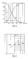
- FIG. 6 is a graphical illustration of the response of low and high pass filters, useful in the system of FIG. 1 ;
- FIG. 7 is a graphical illustration of the response of a limiter useful in the combined noise reducer and visual resolution enhancer of FIG. 5 .
- FIG. 1 illustrates an adaptive image improvement system, constructed and operative in accordance with the present invention.
- the system of the present invention may compensate for the differences between how an image sensor, such as a video camera, views an object and how the human visual system views the same object, producing an image that generally is pleasing to people.
- the present invention may be operative to improve on the output of digital still cameras, printers, internet video, etc.
- the system of FIG. 1 which may comprise an image analyzer 10 , a controller 12 , a human skin processing unit 14 , a noise reducer 16 and a visual resolution enhancer 18 , may operate, at least in part, to improve images, indicated by (YC r C b ), as well as to minimize the undesired effects of common processing operations.
- image analyzer 10 may detect areas of human skin in the input image.
- Human skin processing unit 14 may reduce the saturation of the detected areas of human skin in the image, thereby to reduce the redness of the skin, and visual resolution enhancer 18 may change the high frequency components of areas of the detected human skin to attempt to reduce the sharpness of those areas in the final image.
- the ‘ringing’ effect may occur because the processing may change the intensities of objects or details in the input image so much that they ‘overshoot’ or ‘undershoot’ the intensities that originally were in the object.
- the overshooting and undershooting may be reduced by diminishing the intensity levels of those high frequency components whose intensity levels are above, respectively, a threshold.
- image analyzer 10 may determine the texture level in the details of the image and visual resolution enhancer 18 may operate to increase them if necessary.
- Image analyzer 10 may detect areas of human skin in the input image, and may estimate the amount of low contrast, small details (texture) in the image. Image analyzer 10 may generate an indication of duration of edges at each pixel. In addition, analyzer 10 may determine the locations of details of high brightness and of low brightness, since noise is generally more noticeable in blacker areas, which have low light. Controller 12 may use the analysis to determine a set of parameters to control units 14 , 16 and 18 . Some of these parameters are global, others are per pixel parameters.
- skin processing unit 14 may process the areas of the input image which have skin in them. For low light exposures, areas of human skin may be oversaturated (i.e. the chrominance of such areas may be too high relative to the luminance components). Accordingly, skin processing unit 14 may reduce the chrominance values of such areas. It will be appreciated that an image with no human features in it would pass through unit 14 unedited.
- noise reducer 16 may reduce the noise in the high frequency components to provide sharpness enhancement without an increase in the visibility of the noise.
- visual resolution enhancer 18 may sharpen the output of noise reducer 16 and may operate to increase the spatial depth of the image, as well as its field of view, producing the processed image, indicated by (Y p C rp C bp ).
- analyzer 10 may comprise a skin analyzer 30 , a texture analyzer 32 , a sharpness analyzer 34 and a brightness analyzer 36 .
- Skin analyzer 30 may determine the presence of human skin in the image and may generate a mask SK(i,j) marking the locations of the skin.
- Skin analyzer 30 may comprise a skin detector 40 , a 2D low pass filter 42 and a skin mask generator 44 .
- skin detector 40 may analyze the chrominance signals C r (i,j) and C b (i,j) as follows to determine the location h s (i,j) of not very dark human skin:
- h s ⁇ ( i , j ) ⁇ 1 ⁇ if ⁇ ⁇ C b ⁇ ( i , j ) C s ⁇ ( i , j ) ⁇ D s ⁇ ⁇ and ⁇ ⁇ C r ⁇ ( i , j ) ⁇ D rs ⁇ ⁇ and ⁇ ⁇ C b ⁇ ( i , j ) ⁇ D bs 0 ⁇ otherwise where D s , D rs and D bs are the dynamic ranges for most human skin for
- 2D low pass filter 42 may be any suitable low pass filter and may filter the signal h s to remove noise and any random pixels, such as may come from non-skin areas that happen to meet the criteria but are not skin.
- An exemplary response for low pass filter 42 may be seen in FIG. 6 , to which reference is now briefly made.
- FIG. 6 also shows an exemplary response for high pass filters which may be used in the present invention.
- skin mask generator 44 may generate skin mask SK(i,j) to have a 1 in those locations where the filtered skin signal h s ′ is above a predetermined threshold SKIN (e.g. 3-5 quant (8 bit/pel)).
- SKIN e.g. 3-5 quant (8 bit/pel)
- texture analyzer 32 may comprise a high pass filter 50 .
- An exemplary high pass filter may be that shown in FIG. 6 .
- Analyzer 32 may also comprise a comparator 52 and a texture estimator 54 .
- Comparator 52 may compare the high frequency signal V HF to a base threshold level THD 0 .
- base texture threshold level THD 0 is 3 ⁇ , where ⁇ is a noise dispersion level.
- ⁇ may be 1-2 quant (8 bit/pel).
- n i,j For each pixel (i,j) whose V HF is below base texture threshold level THD 0 , a variable n i,j may receive the value 1. The remaining pixels may receive a 0 value.
- Texture estimator 54 may generate a global texture level ⁇ defined as the percentage of pixels in the image below the texture threshold THD 0 :
- N and M are the number of pixels in the horizontal and vertical directions, respectively.
- Sharpness analyzer 34 may comprise four concatenated delays 60 , four associated adders 62 and a sharpness estimator 64 .
- a sharp image has edges of detail that change sharply from one pixel to the next. However, the edges in a blurry image occur over many pixels. Delays 60 and adders 62 may generate signals indicating how quickly changes occur.
- Each delay 60 may shift the incoming luminance signal Y by one pixel (thus, the output of the fourth adder may be shifted by four pixels) and each adder 62 may subtract the delayed signal produced by its associated delay 60 from the incoming luminance signal Y.
- the resultant signals D 1 , D 2 , D 3 and D 4 may indicate how similar the signal is to its neighbors.
- brightness analyzer 36 may determine the locations of low and bright light and may comprise a low pass filter 70 , a low light mask generator 72 , a bright light mask generator 74 and a bright light coefficient definer 76 .
- Low pass filter 70 may be any suitable low pass filter, such as that shown in FIG. 6 , and may generate a low frequency signal V LF .
- Low light mask generator 72 may review low frequency signal V LF to determine the pixels therein which have an intensity below a low light threshold LL. For example, LL might be 0.3 Y max , where Y max is the maximum allowable intensity value, such as 255. Generator 72 may then generate a mask MASK LL with a positive value, such as 255, for each of the resultant pixels.
- Bright light mask generator 74 may operate similarly to low light mask generator 72 except that the comparison is to a bright light threshold HL above which the intensities should be and the mask may be MASK HL .
- threshold HL might be 0.7 Y max .
- Bright light coefficient generator 76 may generate a per pixel coefficient K HL (i,j) as follows:
- Controller 12 may convert the parameters of analyzer 10 into control parameters for human skin processing unit 14 , noise reducer 16 and visual resolution enhancer 18 .
- Controller 12 may generate a low light skin mask FSK(i,j) which combines both skin mask SK and low light mask MASK LL .
- Controller 12 may generate a visual perception threshold THD above which the human visual system may be able to distinguish details.
- Controller 12 may determine a per pixel, visual resolution enhancement, texture coefficient K t (i,j). This coefficient affects the high frequency components of the image which may be affected by the amount of texture ⁇ as well as the brightness level K HL and may operate to increase the spatial depth and field of view of the image.
- K t0 may be a minimum coefficient level defined from a pre-defined, low noise image. For example, K t0 may be 2-3.
- K sh Another per pixel, visual resolution enhancement coefficient, K sh (i,j), may operate to improve sharpness.
- sharpness coefficient K sh the high frequency components of blurry edge pixels may be increased, thereby sharpening them.
- the sharpening level is higher for blurry edges and lower for already sharp edges.
- Controller 12 may generate a preliminary matrix K s (i,j) from the sharpness estimates SH 1 , SH 2 , SH 3 and SH 4 , as follows:
- K sh0 may be a maximum coefficient level defined from a pre-defined, low noise image.
- K sh0 may be 2 . . . 4.
- Controller 12 may produce the final coefficient K sh (i,j) by including the effects of brightness (in matrix K HL (i,j)) to preliminary coefficient K s (i,j):
- Controller 12 may generate a skin blurring mask K sk for visual resolution enhancer 18 .
- skin mask SK(i,j) indicates that the current pixel has skin in it
- skin blurring mask K sk (i,j) may have a reduction coefficient, as follows:
- K sk0 may be a desired sharpness reduction coefficient for human skin, such as 0.5.
- controller 12 may control the operation of skin processing unit 14 , noise reducer 16 and visual resolution enhancer 18 .
- FIGS. 4 and 5 illustrate the operations of units 14 , 16 and 18 .
- Unit 14 may operate to lower the saturation levels of areas of human skin. Since chrominance levels C r and C b represent the saturation in the input image, unit 14 may operate on them. However, in many systems, such as digital video broadcast systems, chrominance levels C r and C b have an offset value, such as of 128 , which must be removed before processing. To that end, unit 14 may comprise an offset remover 106 to remove the offset, creating signals C r0 and C b0 , and an offset restorer 108 to restore it. The improved chrominance signals may be noted as C rp and C bp .
- unit 14 may comprise a coefficient generator 100 , a switch 102 and two multipliers 104 A and 104 B.
- Coefficient generator 100 may generate a color saturation coefficient K cs , to change the saturation of skin pixels, as follows:
- K cs ⁇ ( i , j ) K cs0 ⁇ ( 1 - Y ⁇ ( i , j ) 0.3 ⁇ ⁇ Y max ) + Y ⁇ ( i , j ) 0.3 ⁇ ⁇ Y max , 0 ⁇ Y ⁇ ( i , j ) ⁇ 0.3 ⁇ ⁇ Y max
- K cs0 is a minimum human skin saturation level, such as 0.7.
- Switch 102 may select the amplification for multipliers 104 for the current pixel (i,j).
- switch 102 may provide the color saturation coefficient K cs (i,j) for the current pixel. Otherwise, switch 102 may provide a unity value (e.g. 1) to multipliers 104 .
- skin processing unit 14 may change its saturation level by changing the intensity levels of chrominance signals C r0 and C b0 .
- FIG. 5 illustrates a combined noise reducer and visual resolution enhancer, labeled 110 , which operates on the luminance signal Y.
- Unit 110 does not affect chrominance signals C rp and C bp produced by skin processing unit 14 since, as is well-known, image sharpness may be defined by the luminance signal Y.
- Unit 110 may divide luminance signal Y into three channels, a low frequency channel (using a 2D low pass filter 112 , such as that of FIG. 6 ) and two high frequency channels, one for the vertical direction (using a high pass filter 114 V, such as that of FIG. 6 ) and one for the horizontal direction (using a high pass filter 114 H, such as that of FIG. 6 ).
- a limiter 116 For each high frequency channel, there is a limiter 116 , two multipliers 118 and 119 , a low pass filter 120 , two adders 122 and 123 and a non-linear operator 124 .
- Each limiter 116 may have any suitable amplitude response.
- An exemplary amplitude response may be that shown in FIG. 7 , to which reference is now briefly made, in which the output is linear until the threshold level THD (where threshold THD is an input from controller 12 ) at which point the output is null (e.g. 0).
- each limiter 116 may select those texture details, which are low contrast, small details found in the high frequency signal V HF , which the human eye may only detect.
- Adders 122 may subtract the limited signal from the high frequency signal V HF to generate signals with contrasting small details that may also be distinguished by the human eye.
- Non-linear operators 124 may operate on the signals with the distinguishable small details, output from adders 122 , to reduce their intensity levels so as to reduce the possibility of over/undershooting after sharpness enhancement. Non-linear operators 124 may more strongly reduce high levels of the signal than lower levels of the signals.
- the multiplication coefficients may be defined as follows:
- K NL ⁇ ( i , j ) 1 - ( 1 - K NL0 ) ⁇ V in ⁇ ( i , j ) V in , max
- V in (i,j) may be the input signal to operators 124
- V in,max may be the maximum possible value of V in , such as 255
- K NL0 may be a user defined value to provide protection against ringing.
- K NL0 might be 0.
- Multipliers 119 may change values per pixel, as per the information provided by parameter K sh (i,j), and may provide sharpness enhancement to the output of non-linear operators 124 .
- the texture signals generated by limiters 116 may be further processed by multiplier 118 , using per pixel, enhancement coefficient K t (i,j). Since such amplification may increase the noise level, the output of multipliers 118 may then be processed through low pass filters 120 to reduce the noise level. It is noted that low pass filter 120 H of the horizontal channel is a vertical low pass filter and low pass filter 120 V of the vertical channel is a horizontal low pass filter.
- Unit 110 may then add the processed texture signals with the sharpened distinguished signals in adders 123 to produce the high frequency horizontal and vertical components. Unit 110 may then add these high frequency components together in an adder 126 . The resultant high frequency signal may be processed, in a multiplier 128 , to reduce the sharpened high frequency signals for those pixels with skin in them.
- the reduction coefficient for multiplier 128 may be skin blurring mask K SK (i,j).
- An adder 130 may add the processed high frequency components to the low frequency components (output of low pass filter 112 ) together to provide an improved luminance signal Y p .
- the improved signals may provide a sharpened image which is more pleasant to the human eye than those of the prior art.
- the output of the present invention may be sharpened but it may have little or no ringing, little or no overly sharpened skin details and reduced noise.
Abstract
Description
where Ds, Drs and Dbs are the dynamic ranges for most human skin for
Cr and Cb, respectively. Applicants have determined empirically that, for many images:
Ds={0.49, . . . 0.91}
Drs={89, . . . , 131}
Dbs={144, . . . 181}
where N and M are the number of pixels in the horizontal and vertical directions, respectively.
SH1(i,j)=1 if D1(i,j)=Dmax
SH2(i,j)=1 if D2(i,j)=Dmax
SH3(i,j)=1 if D3(i,j)=Dmax
SH4(i,j)=1 if D4(i,j)=Dmax
Per pixel coefficient KHL(i,j) may be utilized to increase sharpness for bright light pixels.
FSK(i,j)=SK(i,j)*MASKLL(i,j)
THD=THD0(1+θ)
where Kt0 may be a minimum coefficient level defined from a pre-defined, low noise image. For example, Kt0 may be 2-3.
where Ksh0 may be a maximum coefficient level defined from a pre-defined, low noise image. For example, Ksh0 may be 2 . . . 4. The Ci may be higher for blurry edges (e.g. SH4=1) and lower for sharper edges (e.g. SH1=1). For example:
Ci={0,0.25,0.5,0.75,1},i=0 . . . 4
where Ksk0 may be a desired sharpness reduction coefficient for human skin, such as 0.5.
where Kcs0 is a minimum human skin saturation level, such as 0.7.
where Vin(i,j) may be the input signal to operators 124, Vin,max may be the maximum possible value of Vin, such as 255, and, KNL0 may be a user defined value to provide protection against ringing. In one embodiment, KNL0 might be 0.
Claims (17)
Priority Applications (3)
| Application Number | Priority Date | Filing Date | Title |
|---|---|---|---|
| US10/898,557 US7903902B2 (en) | 2004-07-26 | 2004-07-26 | Adaptive image improvement |
| US11/027,674 US7639892B2 (en) | 2004-07-26 | 2005-01-03 | Adaptive image improvement |
| PCT/IL2005/000751 WO2006011129A2 (en) | 2004-07-26 | 2005-07-14 | Adaptive image improvement |
Applications Claiming Priority (1)
| Application Number | Priority Date | Filing Date | Title |
|---|---|---|---|
| US10/898,557 US7903902B2 (en) | 2004-07-26 | 2004-07-26 | Adaptive image improvement |
Related Child Applications (1)
| Application Number | Title | Priority Date | Filing Date |
|---|---|---|---|
| US11/027,674 Continuation-In-Part US7639892B2 (en) | 2004-07-26 | 2005-01-03 | Adaptive image improvement |
Publications (2)
| Publication Number | Publication Date |
|---|---|
| US20060034512A1 US20060034512A1 (en) | 2006-02-16 |
| US7903902B2 true US7903902B2 (en) | 2011-03-08 |
Family
ID=35656681
Family Applications (1)
| Application Number | Title | Priority Date | Filing Date |
|---|---|---|---|
| US10/898,557 Active 2027-02-01 US7903902B2 (en) | 2004-07-26 | 2004-07-26 | Adaptive image improvement |
Country Status (1)
| Country | Link |
|---|---|
| US (1) | US7903902B2 (en) |
Cited By (4)
| Publication number | Priority date | Publication date | Assignee | Title |
|---|---|---|---|---|
| US20080112637A1 (en) * | 2005-07-21 | 2008-05-15 | Olympus Corporation | Image Processor |
| US20090245633A1 (en) * | 2006-06-09 | 2009-10-01 | Radu Bilcu | Method, a Device, a Module and a Computer Program Product for Determining the Quality of an Image |
| US20100225817A1 (en) * | 2000-06-28 | 2010-09-09 | Sheraizin Semion M | Real Time Motion Picture Segmentation and Superposition |
| US20110097008A1 (en) * | 2007-08-07 | 2011-04-28 | Dxo Labs | Method for processing a digital object and related system |
Families Citing this family (10)
| Publication number | Priority date | Publication date | Assignee | Title |
|---|---|---|---|---|
| KR100565209B1 (en) * | 2004-08-11 | 2006-03-30 | 엘지전자 주식회사 | Apparatus and method for improving image sharpness based on human visual system |
| CN101123677B (en) | 2006-08-11 | 2011-03-02 | 松下电器产业株式会社 | Method, device and integrated circuit for improving image acuteness |
| KR101341101B1 (en) * | 2007-09-11 | 2013-12-13 | 삼성전기주식회사 | Apparatus and Method for restoring image |
| US8913668B2 (en) * | 2008-09-29 | 2014-12-16 | Microsoft Corporation | Perceptual mechanism for the selection of residues in video coders |
| US8457194B2 (en) * | 2008-09-29 | 2013-06-04 | Microsoft Corporation | Processing real-time video |
| KR101978172B1 (en) * | 2011-11-29 | 2019-05-15 | 삼성전자주식회사 | Method and apparatus for converting depth image to high-resolution |
| US9324133B2 (en) | 2012-01-04 | 2016-04-26 | Sharp Laboratories Of America, Inc. | Image content enhancement using a dictionary technique |
| US10055821B2 (en) * | 2016-01-30 | 2018-08-21 | John W. Glotzbach | Device for and method of enhancing quality of an image |
| EP3460747B1 (en) * | 2017-09-25 | 2023-09-06 | Vestel Elektronik Sanayi ve Ticaret A.S. | Method, processing system and computer program for processing an image |
| CN111814520A (en) * | 2019-04-12 | 2020-10-23 | 虹软科技股份有限公司 | Skin type detection method, skin type grade classification method, and skin type detection device |
Citations (126)
| Publication number | Priority date | Publication date | Assignee | Title |
|---|---|---|---|---|
| US2697758A (en) | 1950-08-01 | 1954-12-21 | Rca Corp | Gamma correcting circuit |
| US3961133A (en) | 1974-05-24 | 1976-06-01 | The Singer Company | Method and apparatus for combining video images with proper occlusion |
| GB1503612A (en) | 1974-02-19 | 1978-03-15 | Sonex Int Corp | Arrangements for keying video signals |
| US4855825A (en) | 1984-06-08 | 1989-08-08 | Valtion Teknillinen Tutkimuskeskus | Method and apparatus for detecting the most powerfully changed picture areas in a live video signal |
| US4947255A (en) | 1988-09-19 | 1990-08-07 | The Grass Valley Group, Inc. | Video luminance self keyer |
| US5012333A (en) | 1989-01-05 | 1991-04-30 | Eastman Kodak Company | Interactive dynamic range adjustment system for printing digital images |
| US5126847A (en) | 1989-09-28 | 1992-06-30 | Sony Corporation | Apparatus for producing a composite signal from real moving picture and still picture video signals |
| US5194943A (en) | 1990-11-06 | 1993-03-16 | Hitachi, Ltd. | Video camera having a γ-correction circuit for correcting level characteristics of a luminance signal included in a video signal |
| US5245445A (en) | 1991-03-22 | 1993-09-14 | Ricoh Company, Ltd. | Image processing apparatus |
| US5301016A (en) | 1991-12-21 | 1994-04-05 | U.S. Philips Corporation | Method of and arrangement for deriving a control signal for inserting a background signal into parts of a foreground signal |
| US5339171A (en) | 1990-04-24 | 1994-08-16 | Ricoh Company, Ltd. | Image processing apparatus especially suitable for producing smooth-edged output multi-level tone data having fewer levels than input multi-level tone data |
| US5341442A (en) | 1992-01-21 | 1994-08-23 | Supermac Technology, Inc. | Method and apparatus for compression data by generating base image data from luminance and chrominance components and detail image data from luminance component |
| US5384601A (en) | 1992-08-25 | 1995-01-24 | Matsushita Electric Industrial Co., Ltd. | Color adjustment apparatus for automatically changing colors |
| US5404174A (en) | 1992-06-29 | 1995-04-04 | Victor Company Of Japan, Ltd. | Scene change detector for detecting a scene change of a moving picture |
| US5428398A (en) | 1992-04-10 | 1995-06-27 | Faroudja; Yves C. | Method and apparatus for producing from a standard-bandwidth television signal a signal which when reproduced provides a high-definition-like video image relatively free of artifacts |
| US5467404A (en) | 1991-08-14 | 1995-11-14 | Agfa-Gevaert | Method and apparatus for contrast enhancement |
| US5488675A (en) | 1994-03-31 | 1996-01-30 | David Sarnoff Research Center, Inc. | Stabilizing estimate of location of target region inferred from tracked multiple landmark regions of a video image |
| US5491517A (en) | 1994-03-14 | 1996-02-13 | Scitex America Corporation | System for implanting an image into a video stream |
| US5491514A (en) | 1993-01-28 | 1996-02-13 | Matsushita Electric Industrial Co., Ltd. | Coding apparatus, decoding apparatus, coding-decoding apparatus for video signals, and optical disks conforming thereto |
| US5491519A (en) | 1993-12-16 | 1996-02-13 | Daewoo Electronics Co., Ltd. | Pre-processing filter apparatus for use in an image encoding system |
| US5510824A (en) | 1993-07-26 | 1996-04-23 | Texas Instruments, Inc. | Spatial light modulator array |
| US5537510A (en) | 1994-12-30 | 1996-07-16 | Daewoo Electronics Co., Ltd. | Adaptive digital audio encoding apparatus and a bit allocation method thereof |
| US5539475A (en) | 1993-09-10 | 1996-07-23 | Sony Corporation | Method of and apparatus for deriving a key signal from a digital video signal |
| US5542008A (en) | 1990-02-28 | 1996-07-30 | Victor Company Of Japan, Ltd. | Method of and apparatus for compressing image representing signals |
| US5555557A (en) | 1990-04-23 | 1996-09-10 | Xerox Corporation | Bit-map image resolution converter with controlled compensation for write-white xerographic laser printing |
| US5557340A (en) | 1990-12-13 | 1996-09-17 | Rank Cintel Limited | Noise reduction in video signals |
| US5565921A (en) | 1993-03-16 | 1996-10-15 | Olympus Optical Co., Ltd. | Motion-adaptive image signal processing system |
| US5566251A (en) | 1991-09-18 | 1996-10-15 | David Sarnoff Research Center, Inc | Video merging employing pattern-key insertion |
| US5586200A (en) | 1994-01-07 | 1996-12-17 | Panasonic Technologies, Inc. | Segmentation based image compression system |
| US5592226A (en) | 1994-01-26 | 1997-01-07 | Btg Usa Inc. | Method and apparatus for video data compression using temporally adaptive motion interpolation |
| US5613035A (en) | 1994-01-18 | 1997-03-18 | Daewoo Electronics Co., Ltd. | Apparatus for adaptively encoding input digital audio signals from a plurality of channels |
| US5627937A (en) | 1995-01-09 | 1997-05-06 | Daewoo Electronics Co. Ltd. | Apparatus for adaptively encoding input digital audio signals from a plurality of channels |
| US5648801A (en) | 1994-12-16 | 1997-07-15 | International Business Machines Corporation | Grayscale printing system |
| US5653234A (en) | 1995-09-29 | 1997-08-05 | Siemens Medical Systems, Inc. | Method and apparatus for adaptive spatial image filtering |
| US5694492A (en) | 1994-04-30 | 1997-12-02 | Daewoo Electronics Co., Ltd | Post-processing method and apparatus for removing a blocking effect in a decoded image signal |
| US5717463A (en) | 1995-07-24 | 1998-02-10 | Motorola, Inc. | Method and system for estimating motion within a video sequence |
| EP0502615B1 (en) | 1991-03-07 | 1998-06-03 | Matsushita Electric Industrial Co., Ltd. | Video signal motion detection method and noise reducer using said method |
| US5774593A (en) | 1995-07-24 | 1998-06-30 | University Of Washington | Automatic scene decomposition and optimization of MPEG compressed video |
| US5787203A (en) | 1996-01-19 | 1998-07-28 | Microsoft Corporation | Method and system for filtering compressed video images |
| US5790195A (en) | 1993-12-28 | 1998-08-04 | Canon Kabushiki Kaisha | Image processing apparatus |
| US5796864A (en) | 1992-05-12 | 1998-08-18 | Apple Computer, Inc. | Method and apparatus for real-time lossless compression and decompression of image data |
| US5799111A (en) | 1991-06-14 | 1998-08-25 | D.V.P. Technologies, Ltd. | Apparatus and methods for smoothing images |
| US5828776A (en) * | 1994-09-20 | 1998-10-27 | Neopath, Inc. | Apparatus for identification and integration of multiple cell patterns |
| US5838835A (en) | 1994-05-03 | 1998-11-17 | U.S. Philips Corporation | Better contrast noise by residue image |
| US5844607A (en) | 1996-04-03 | 1998-12-01 | International Business Machines Corporation | Method and apparatus for scene change detection in digital video compression |
| US5845012A (en) | 1995-03-20 | 1998-12-01 | Daewoo Electronics Co., Ltd. | Apparatus for encoding an image signal having a still object |
| US5847772A (en) | 1996-09-11 | 1998-12-08 | Wells; Aaron | Adaptive filter for video processing applications |
| US5847766A (en) | 1994-05-31 | 1998-12-08 | Samsung Electronics Co, Ltd. | Video encoding method and apparatus based on human visual sensitivity |
| US5850294A (en) | 1995-12-18 | 1998-12-15 | Lucent Technologies Inc. | Method and apparatus for post-processing images |
| US5852475A (en) | 1995-06-06 | 1998-12-22 | Compression Labs, Inc. | Transform artifact reduction process |
| US5870501A (en) | 1996-07-11 | 1999-02-09 | Daewoo Electronics, Co., Ltd. | Method and apparatus for encoding a contour image in a video signal |
| US5881174A (en) | 1997-02-18 | 1999-03-09 | Daewoo Electronics Co., Ltd. | Method and apparatus for adaptively coding a contour of an object |
| US5883983A (en) | 1996-03-23 | 1999-03-16 | Samsung Electronics Co., Ltd. | Adaptive postprocessing system for reducing blocking effects and ringing noise in decompressed image signals |
| US5881614A (en) | 1996-12-09 | 1999-03-16 | Millers Falls Tool Company | Tool with reversible bit and method of assembly |
| US5901178A (en) | 1996-02-26 | 1999-05-04 | Solana Technology Development Corporation | Post-compression hidden data transport for video |
| US5914748A (en) | 1996-08-30 | 1999-06-22 | Eastman Kodak Company | Method and apparatus for generating a composite image using the difference of two images |
| US5974159A (en) | 1996-03-29 | 1999-10-26 | Sarnoff Corporation | Method and apparatus for assessing the visibility of differences between two image sequences |
| US5982926A (en) | 1995-01-17 | 1999-11-09 | At & T Ipm Corp. | Real-time image enhancement techniques |
| US5991464A (en) | 1998-04-03 | 1999-11-23 | Odyssey Technologies | Method and system for adaptive video image resolution enhancement |
| US5995656A (en) | 1996-05-21 | 1999-11-30 | Samsung Electronics Co., Ltd. | Image enhancing method using lowpass filtering and histogram equalization and a device therefor |
| US6005626A (en) | 1997-01-09 | 1999-12-21 | Sun Microsystems, Inc. | Digital video signal encoder and encoding method |
| US6014172A (en) | 1997-03-21 | 2000-01-11 | Trw Inc. | Optimized video compression from a single process step |
| US6037986A (en) | 1996-07-16 | 2000-03-14 | Divicom Inc. | Video preprocessing method and apparatus with selective filtering based on motion detection |
| US6055340A (en) | 1997-02-28 | 2000-04-25 | Fuji Photo Film Co., Ltd. | Method and apparatus for processing digital images to suppress their noise and enhancing their sharpness |
| US6094511A (en) * | 1996-07-31 | 2000-07-25 | Canon Kabushiki Kaisha | Image filtering method and apparatus with interpolation according to mapping function to produce final image |
| US6097848A (en) | 1997-11-03 | 2000-08-01 | Welch Allyn, Inc. | Noise reduction apparatus for electronic edge enhancement |
| US6100625A (en) * | 1997-11-10 | 2000-08-08 | Nec Corporation | Piezoelectric ceramic transducer and method of forming the same |
| US6130723A (en) | 1998-01-15 | 2000-10-10 | Innovision Corporation | Method and system for improving image quality on an interlaced video display |
| US6191772B1 (en) | 1992-11-02 | 2001-02-20 | Cagent Technologies, Inc. | Resolution enhancement for video display using multi-line interpolation |
| US20010000354A1 (en) | 1991-09-26 | 2001-04-19 | Greg Nazerian | Wire marking, cutting and stripping apparatus and method |
| US6229925B1 (en) | 1997-05-27 | 2001-05-08 | Thomas Broadcast Systems | Pre-processing device for MPEG 2 coding |
| US6236751B1 (en) | 1998-09-23 | 2001-05-22 | Xerox Corporation | Automatic method for determining piecewise linear transformation from an image histogram |
| US6259489B1 (en) | 1996-04-12 | 2001-07-10 | Snell & Wilcox Limited | Video noise reducer |
| US6282299B1 (en) | 1996-08-30 | 2001-08-28 | Regents Of The University Of Minnesota | Method and apparatus for video watermarking using perceptual masks |
| US6320676B1 (en) | 1997-02-04 | 2001-11-20 | Fuji Photo Film Co., Ltd. | Method of predicting and processing image fine structures |
| EP0729117B1 (en) | 1995-02-21 | 2001-11-21 | Hitachi, Ltd. | Method and apparatus for detecting a point of change in moving images |
| US20020015508A1 (en) | 2000-06-19 | 2002-02-07 | Digimarc Corporation | Perceptual modeling of media signals based on local contrast and directional edges |
| US6366705B1 (en) | 1999-01-28 | 2002-04-02 | Lucent Technologies Inc. | Perceptual preprocessing techniques to reduce complexity of video coders |
| US6385647B1 (en) | 1997-08-18 | 2002-05-07 | Mci Communications Corporations | System for selectively routing data via either a network that supports Internet protocol or via satellite transmission network based on size of the data |
| US6404460B1 (en) | 1999-02-19 | 2002-06-11 | Omnivision Technologies, Inc. | Edge enhancement with background noise reduction in video image processing |
| US20020104854A1 (en) | 2001-01-24 | 2002-08-08 | Jensen Bjorn Slot | Dosing spout for mounting on a container |
| US20020122494A1 (en) | 2000-12-27 | 2002-09-05 | Sheraizin Vitaly S. | Method and apparatus for visual perception encoding |
| US6463173B1 (en) | 1995-10-30 | 2002-10-08 | Hewlett-Packard Company | System and method for histogram-based image contrast enhancement |
| US6466912B1 (en) | 1997-09-25 | 2002-10-15 | At&T Corp. | Perceptual coding of audio signals employing envelope uncertainty |
| US6473532B1 (en) | 2000-01-23 | 2002-10-29 | Vls Com Ltd. | Method and apparatus for visual lossless image syntactic encoding |
| US20020181598A1 (en) | 2001-04-16 | 2002-12-05 | Mitsubishi Electric Research Laboratories, Inc. | Estimating total average distortion in a video with variable frameskip |
| US6509158B1 (en) * | 1988-09-15 | 2003-01-21 | Wisconsin Alumni Research Foundation | Image processing and analysis of individual nucleic acid molecules |
| US6554181B1 (en) * | 1998-02-09 | 2003-04-29 | Sig Combibloc Gmbh & Co. Kg | Reclosable pouring element and a flat gable composite packaging provided therewith |
| US6559826B1 (en) | 1998-11-06 | 2003-05-06 | Silicon Graphics, Inc. | Method for modeling and updating a colorimetric reference profile for a flat panel display |
| US6567116B1 (en) * | 1998-11-20 | 2003-05-20 | James A. Aman | Multiple object tracking system |
| US20030107681A1 (en) | 2001-12-12 | 2003-06-12 | Masayuki Otawara | Contrast correcting circuit |
| US6580825B2 (en) | 1999-05-13 | 2003-06-17 | Hewlett-Packard Company | Contrast enhancement of an image using luminance and RGB statistical metrics |
| US20030122969A1 (en) | 2001-11-08 | 2003-07-03 | Olympus Optical Co., Ltd. | Noise reduction system, noise reduction method, recording medium, and electronic camera |
| US20030152283A1 (en) | 1998-08-05 | 2003-08-14 | Kagumi Moriwaki | Image correction device, image correction method and computer program product in memory for image correction |
| US6610256B2 (en) * | 1989-04-05 | 2003-08-26 | Wisconsin Alumni Research Foundation | Image processing and analysis of individual nucleic acid molecules |
| US6628327B1 (en) | 1997-01-08 | 2003-09-30 | Ricoh Co., Ltd | Method and a system for improving resolution in color image data generated by a color image sensor |
| US6707487B1 (en) * | 1998-11-20 | 2004-03-16 | In The Play, Inc. | Method for representing real-time motion |
| US6728317B1 (en) | 1996-01-30 | 2004-04-27 | Dolby Laboratories Licensing Corporation | Moving image compression quality enhancement using displacement filters with negative lobes |
| US20040091145A1 (en) | 2002-04-11 | 2004-05-13 | Atsushi Kohashi | Image signal processing system and camera having the image signal processing system |
| US6753929B1 (en) | 2000-06-28 | 2004-06-22 | Vls Com Ltd. | Method and system for real time motion picture segmentation and superposition |
| US6757449B1 (en) | 1999-11-17 | 2004-06-29 | Xerox Corporation | Methods and systems for processing anti-aliased images |
| US6782287B2 (en) * | 2000-06-27 | 2004-08-24 | The Board Of Trustees Of The Leland Stanford Junior University | Method and apparatus for tracking a medical instrument based on image registration |
| US20040184673A1 (en) | 2003-03-17 | 2004-09-23 | Oki Data Corporation | Image processing method and image processing apparatus |
| US20040190789A1 (en) | 2003-03-26 | 2004-09-30 | Microsoft Corporation | Automatic analysis and adjustment of digital images with exposure problems |
| US6835693B2 (en) | 2002-11-12 | 2004-12-28 | Eastman Kodak Company | Composite positioning imaging element |
| US6845181B2 (en) | 2001-07-12 | 2005-01-18 | Eastman Kodak Company | Method for processing a digital image to adjust brightness |
| US20050013485A1 (en) | 1999-06-25 | 2005-01-20 | Minolta Co., Ltd. | Image processor |
| US6847391B1 (en) * | 1988-10-17 | 2005-01-25 | Lord Samuel Anthony Kassatly | Multi-point video conference system |
| US6873442B1 (en) | 2000-11-07 | 2005-03-29 | Eastman Kodak Company | Method and system for generating a low resolution image from a sparsely sampled extended dynamic range image sensing device |
| US6940545B1 (en) | 2000-02-28 | 2005-09-06 | Eastman Kodak Company | Face detecting camera and method |
| US6940903B2 (en) | 2001-03-05 | 2005-09-06 | Intervideo, Inc. | Systems and methods for performing bit rate allocation for a video data stream |
| US20050259185A1 (en) | 2004-05-21 | 2005-11-24 | Moon-Cheol Kim | Gamma correction apparatus and method capable of preventing noise boost-up |
| US20060013503A1 (en) | 2004-07-16 | 2006-01-19 | Samsung Electronics Co., Ltd. | Methods of preventing noise boost in image contrast enhancement |
| US7003174B2 (en) * | 2001-07-02 | 2006-02-21 | Corel Corporation | Removal of block encoding artifacts |
| US7050961B1 (en) * | 2001-03-21 | 2006-05-23 | Unisys Corporation | Solution generation method for thin client sizing tool |
| US7075993B2 (en) * | 2001-06-12 | 2006-07-11 | Digital Interactive Streams, Inc. | Correction system and method for enhancing digital video |
| US7087021B2 (en) * | 2001-02-20 | 2006-08-08 | Giovanni Paternostro | Methods of screening for genes and agents affecting cardiac function |
| US7110601B2 (en) * | 2001-10-25 | 2006-09-19 | Japan Aerospace Exploration Agency | Method for detecting linear image in planar picture |
| US7112762B2 (en) * | 2004-09-30 | 2006-09-26 | Siemens Energy & Automation, Inc. | Systems for correcting slow roll |
| US7124041B1 (en) * | 2004-09-27 | 2006-10-17 | Siemens Energy & Automotive, Inc. | Systems, methods, and devices for detecting circuit faults |
| US7139425B2 (en) | 2000-08-28 | 2006-11-21 | Fuji Photo Film Co., Ltd. | Method and apparatus for correcting white balance, method for correcting density and a recording medium on which a program for carrying out the methods is recorded |
| US7181370B2 (en) * | 2003-08-26 | 2007-02-20 | Siemens Energy & Automation, Inc. | System and method for remotely obtaining and managing machine data |
| US7184071B2 (en) * | 2002-08-23 | 2007-02-27 | University Of Maryland | Method of three-dimensional object reconstruction from a video sequence using a generic model |
| US7221805B1 (en) * | 2001-12-21 | 2007-05-22 | Cognex Technology And Investment Corporation | Method for generating a focused image of an object |
| US7526142B2 (en) | 2005-02-22 | 2009-04-28 | Sheraizin Vitaly S | Enhancement of decompressed video |
| US7639892B2 (en) | 2004-07-26 | 2009-12-29 | Sheraizin Semion M | Adaptive image improvement |
Family Cites Families (2)
| Publication number | Priority date | Publication date | Assignee | Title |
|---|---|---|---|---|
| US6544181B1 (en) * | 1999-03-05 | 2003-04-08 | The General Hospital Corporation | Method and apparatus for measuring volume flow and area for a dynamic orifice |
| WO2003036149A2 (en) * | 2001-10-22 | 2003-05-01 | Compagnie Plastic Omnium Corp. | Welded, plastic flange connection |
-
2004
- 2004-07-26 US US10/898,557 patent/US7903902B2/en active Active
Patent Citations (139)
| Publication number | Priority date | Publication date | Assignee | Title |
|---|---|---|---|---|
| US2697758A (en) | 1950-08-01 | 1954-12-21 | Rca Corp | Gamma correcting circuit |
| GB1503612A (en) | 1974-02-19 | 1978-03-15 | Sonex Int Corp | Arrangements for keying video signals |
| US3961133A (en) | 1974-05-24 | 1976-06-01 | The Singer Company | Method and apparatus for combining video images with proper occlusion |
| US4855825A (en) | 1984-06-08 | 1989-08-08 | Valtion Teknillinen Tutkimuskeskus | Method and apparatus for detecting the most powerfully changed picture areas in a live video signal |
| US6509158B1 (en) * | 1988-09-15 | 2003-01-21 | Wisconsin Alumni Research Foundation | Image processing and analysis of individual nucleic acid molecules |
| US7049074B2 (en) * | 1988-09-15 | 2006-05-23 | Wisconsin Alumni Research Foundation | Methods and compositions for the manipulation and characterization of individual nucleic acid molecules |
| US4947255A (en) | 1988-09-19 | 1990-08-07 | The Grass Valley Group, Inc. | Video luminance self keyer |
| US6847391B1 (en) * | 1988-10-17 | 2005-01-25 | Lord Samuel Anthony Kassatly | Multi-point video conference system |
| US5012333A (en) | 1989-01-05 | 1991-04-30 | Eastman Kodak Company | Interactive dynamic range adjustment system for printing digital images |
| US6610256B2 (en) * | 1989-04-05 | 2003-08-26 | Wisconsin Alumni Research Foundation | Image processing and analysis of individual nucleic acid molecules |
| US5126847A (en) | 1989-09-28 | 1992-06-30 | Sony Corporation | Apparatus for producing a composite signal from real moving picture and still picture video signals |
| US5542008A (en) | 1990-02-28 | 1996-07-30 | Victor Company Of Japan, Ltd. | Method of and apparatus for compressing image representing signals |
| US5555557A (en) | 1990-04-23 | 1996-09-10 | Xerox Corporation | Bit-map image resolution converter with controlled compensation for write-white xerographic laser printing |
| US5339171A (en) | 1990-04-24 | 1994-08-16 | Ricoh Company, Ltd. | Image processing apparatus especially suitable for producing smooth-edged output multi-level tone data having fewer levels than input multi-level tone data |
| US5194943A (en) | 1990-11-06 | 1993-03-16 | Hitachi, Ltd. | Video camera having a γ-correction circuit for correcting level characteristics of a luminance signal included in a video signal |
| US5557340A (en) | 1990-12-13 | 1996-09-17 | Rank Cintel Limited | Noise reduction in video signals |
| EP0502615B1 (en) | 1991-03-07 | 1998-06-03 | Matsushita Electric Industrial Co., Ltd. | Video signal motion detection method and noise reducer using said method |
| US5245445A (en) | 1991-03-22 | 1993-09-14 | Ricoh Company, Ltd. | Image processing apparatus |
| US5799111A (en) | 1991-06-14 | 1998-08-25 | D.V.P. Technologies, Ltd. | Apparatus and methods for smoothing images |
| US5467404A (en) | 1991-08-14 | 1995-11-14 | Agfa-Gevaert | Method and apparatus for contrast enhancement |
| US5566251A (en) | 1991-09-18 | 1996-10-15 | David Sarnoff Research Center, Inc | Video merging employing pattern-key insertion |
| US20010000354A1 (en) | 1991-09-26 | 2001-04-19 | Greg Nazerian | Wire marking, cutting and stripping apparatus and method |
| US5301016A (en) | 1991-12-21 | 1994-04-05 | U.S. Philips Corporation | Method of and arrangement for deriving a control signal for inserting a background signal into parts of a foreground signal |
| US5341442A (en) | 1992-01-21 | 1994-08-23 | Supermac Technology, Inc. | Method and apparatus for compression data by generating base image data from luminance and chrominance components and detail image data from luminance component |
| US5428398A (en) | 1992-04-10 | 1995-06-27 | Faroudja; Yves C. | Method and apparatus for producing from a standard-bandwidth television signal a signal which when reproduced provides a high-definition-like video image relatively free of artifacts |
| US5796864A (en) | 1992-05-12 | 1998-08-18 | Apple Computer, Inc. | Method and apparatus for real-time lossless compression and decompression of image data |
| US5404174A (en) | 1992-06-29 | 1995-04-04 | Victor Company Of Japan, Ltd. | Scene change detector for detecting a scene change of a moving picture |
| US5384601A (en) | 1992-08-25 | 1995-01-24 | Matsushita Electric Industrial Co., Ltd. | Color adjustment apparatus for automatically changing colors |
| US6191772B1 (en) | 1992-11-02 | 2001-02-20 | Cagent Technologies, Inc. | Resolution enhancement for video display using multi-line interpolation |
| US5491514A (en) | 1993-01-28 | 1996-02-13 | Matsushita Electric Industrial Co., Ltd. | Coding apparatus, decoding apparatus, coding-decoding apparatus for video signals, and optical disks conforming thereto |
| US5565921A (en) | 1993-03-16 | 1996-10-15 | Olympus Optical Co., Ltd. | Motion-adaptive image signal processing system |
| US5510824A (en) | 1993-07-26 | 1996-04-23 | Texas Instruments, Inc. | Spatial light modulator array |
| US5614937A (en) | 1993-07-26 | 1997-03-25 | Texas Instruments Incorporated | Method for high resolution printing |
| US5627580A (en) | 1993-07-26 | 1997-05-06 | Texas Instruments Incorporated | System and method for enhanced printing |
| US5539475A (en) | 1993-09-10 | 1996-07-23 | Sony Corporation | Method of and apparatus for deriving a key signal from a digital video signal |
| US5491519A (en) | 1993-12-16 | 1996-02-13 | Daewoo Electronics Co., Ltd. | Pre-processing filter apparatus for use in an image encoding system |
| US5790195A (en) | 1993-12-28 | 1998-08-04 | Canon Kabushiki Kaisha | Image processing apparatus |
| US5586200A (en) | 1994-01-07 | 1996-12-17 | Panasonic Technologies, Inc. | Segmentation based image compression system |
| US5613035A (en) | 1994-01-18 | 1997-03-18 | Daewoo Electronics Co., Ltd. | Apparatus for adaptively encoding input digital audio signals from a plurality of channels |
| US5592226A (en) | 1994-01-26 | 1997-01-07 | Btg Usa Inc. | Method and apparatus for video data compression using temporally adaptive motion interpolation |
| US5491517A (en) | 1994-03-14 | 1996-02-13 | Scitex America Corporation | System for implanting an image into a video stream |
| US5488675A (en) | 1994-03-31 | 1996-01-30 | David Sarnoff Research Center, Inc. | Stabilizing estimate of location of target region inferred from tracked multiple landmark regions of a video image |
| US5694492A (en) | 1994-04-30 | 1997-12-02 | Daewoo Electronics Co., Ltd | Post-processing method and apparatus for removing a blocking effect in a decoded image signal |
| US5838835A (en) | 1994-05-03 | 1998-11-17 | U.S. Philips Corporation | Better contrast noise by residue image |
| US5847766A (en) | 1994-05-31 | 1998-12-08 | Samsung Electronics Co, Ltd. | Video encoding method and apparatus based on human visual sensitivity |
| US5828776A (en) * | 1994-09-20 | 1998-10-27 | Neopath, Inc. | Apparatus for identification and integration of multiple cell patterns |
| US5648801A (en) | 1994-12-16 | 1997-07-15 | International Business Machines Corporation | Grayscale printing system |
| US5537510A (en) | 1994-12-30 | 1996-07-16 | Daewoo Electronics Co., Ltd. | Adaptive digital audio encoding apparatus and a bit allocation method thereof |
| US5627937A (en) | 1995-01-09 | 1997-05-06 | Daewoo Electronics Co. Ltd. | Apparatus for adaptively encoding input digital audio signals from a plurality of channels |
| US5982926A (en) | 1995-01-17 | 1999-11-09 | At & T Ipm Corp. | Real-time image enhancement techniques |
| EP0729117B1 (en) | 1995-02-21 | 2001-11-21 | Hitachi, Ltd. | Method and apparatus for detecting a point of change in moving images |
| US5845012A (en) | 1995-03-20 | 1998-12-01 | Daewoo Electronics Co., Ltd. | Apparatus for encoding an image signal having a still object |
| US5852475A (en) | 1995-06-06 | 1998-12-22 | Compression Labs, Inc. | Transform artifact reduction process |
| US5717463A (en) | 1995-07-24 | 1998-02-10 | Motorola, Inc. | Method and system for estimating motion within a video sequence |
| US5774593A (en) | 1995-07-24 | 1998-06-30 | University Of Washington | Automatic scene decomposition and optimization of MPEG compressed video |
| US5653234A (en) | 1995-09-29 | 1997-08-05 | Siemens Medical Systems, Inc. | Method and apparatus for adaptive spatial image filtering |
| US6463173B1 (en) | 1995-10-30 | 2002-10-08 | Hewlett-Packard Company | System and method for histogram-based image contrast enhancement |
| US5850294A (en) | 1995-12-18 | 1998-12-15 | Lucent Technologies Inc. | Method and apparatus for post-processing images |
| US5787203A (en) | 1996-01-19 | 1998-07-28 | Microsoft Corporation | Method and system for filtering compressed video images |
| US6728317B1 (en) | 1996-01-30 | 2004-04-27 | Dolby Laboratories Licensing Corporation | Moving image compression quality enhancement using displacement filters with negative lobes |
| US5901178A (en) | 1996-02-26 | 1999-05-04 | Solana Technology Development Corporation | Post-compression hidden data transport for video |
| US5883983A (en) | 1996-03-23 | 1999-03-16 | Samsung Electronics Co., Ltd. | Adaptive postprocessing system for reducing blocking effects and ringing noise in decompressed image signals |
| US5974159A (en) | 1996-03-29 | 1999-10-26 | Sarnoff Corporation | Method and apparatus for assessing the visibility of differences between two image sequences |
| US5844607A (en) | 1996-04-03 | 1998-12-01 | International Business Machines Corporation | Method and apparatus for scene change detection in digital video compression |
| US6259489B1 (en) | 1996-04-12 | 2001-07-10 | Snell & Wilcox Limited | Video noise reducer |
| US5995656A (en) | 1996-05-21 | 1999-11-30 | Samsung Electronics Co., Ltd. | Image enhancing method using lowpass filtering and histogram equalization and a device therefor |
| US5870501A (en) | 1996-07-11 | 1999-02-09 | Daewoo Electronics, Co., Ltd. | Method and apparatus for encoding a contour image in a video signal |
| US6037986A (en) | 1996-07-16 | 2000-03-14 | Divicom Inc. | Video preprocessing method and apparatus with selective filtering based on motion detection |
| US6094511A (en) * | 1996-07-31 | 2000-07-25 | Canon Kabushiki Kaisha | Image filtering method and apparatus with interpolation according to mapping function to produce final image |
| US6282299B1 (en) | 1996-08-30 | 2001-08-28 | Regents Of The University Of Minnesota | Method and apparatus for video watermarking using perceptual masks |
| US5914748A (en) | 1996-08-30 | 1999-06-22 | Eastman Kodak Company | Method and apparatus for generating a composite image using the difference of two images |
| US5847772A (en) | 1996-09-11 | 1998-12-08 | Wells; Aaron | Adaptive filter for video processing applications |
| US5881614A (en) | 1996-12-09 | 1999-03-16 | Millers Falls Tool Company | Tool with reversible bit and method of assembly |
| US6628327B1 (en) | 1997-01-08 | 2003-09-30 | Ricoh Co., Ltd | Method and a system for improving resolution in color image data generated by a color image sensor |
| US6005626A (en) | 1997-01-09 | 1999-12-21 | Sun Microsystems, Inc. | Digital video signal encoder and encoding method |
| US6320676B1 (en) | 1997-02-04 | 2001-11-20 | Fuji Photo Film Co., Ltd. | Method of predicting and processing image fine structures |
| US6522425B2 (en) | 1997-02-04 | 2003-02-18 | Fuji Photo Film Co., Ltd. | Method of predicting and processing image fine structures |
| US5881174A (en) | 1997-02-18 | 1999-03-09 | Daewoo Electronics Co., Ltd. | Method and apparatus for adaptively coding a contour of an object |
| US6055340A (en) | 1997-02-28 | 2000-04-25 | Fuji Photo Film Co., Ltd. | Method and apparatus for processing digital images to suppress their noise and enhancing their sharpness |
| US6014172A (en) | 1997-03-21 | 2000-01-11 | Trw Inc. | Optimized video compression from a single process step |
| US6229925B1 (en) | 1997-05-27 | 2001-05-08 | Thomas Broadcast Systems | Pre-processing device for MPEG 2 coding |
| US6385647B1 (en) | 1997-08-18 | 2002-05-07 | Mci Communications Corporations | System for selectively routing data via either a network that supports Internet protocol or via satellite transmission network based on size of the data |
| US6466912B1 (en) | 1997-09-25 | 2002-10-15 | At&T Corp. | Perceptual coding of audio signals employing envelope uncertainty |
| US6097848A (en) | 1997-11-03 | 2000-08-01 | Welch Allyn, Inc. | Noise reduction apparatus for electronic edge enhancement |
| US6100625A (en) * | 1997-11-10 | 2000-08-08 | Nec Corporation | Piezoelectric ceramic transducer and method of forming the same |
| US6130723A (en) | 1998-01-15 | 2000-10-10 | Innovision Corporation | Method and system for improving image quality on an interlaced video display |
| US6554181B1 (en) * | 1998-02-09 | 2003-04-29 | Sig Combibloc Gmbh & Co. Kg | Reclosable pouring element and a flat gable composite packaging provided therewith |
| US5991464A (en) | 1998-04-03 | 1999-11-23 | Odyssey Technologies | Method and system for adaptive video image resolution enhancement |
| US6643398B2 (en) | 1998-08-05 | 2003-11-04 | Minolta Co., Ltd. | Image correction device, image correction method and computer program product in memory for image correction |
| US20030152283A1 (en) | 1998-08-05 | 2003-08-14 | Kagumi Moriwaki | Image correction device, image correction method and computer program product in memory for image correction |
| US6236751B1 (en) | 1998-09-23 | 2001-05-22 | Xerox Corporation | Automatic method for determining piecewise linear transformation from an image histogram |
| US6559826B1 (en) | 1998-11-06 | 2003-05-06 | Silicon Graphics, Inc. | Method for modeling and updating a colorimetric reference profile for a flat panel display |
| US6567116B1 (en) * | 1998-11-20 | 2003-05-20 | James A. Aman | Multiple object tracking system |
| US6707487B1 (en) * | 1998-11-20 | 2004-03-16 | In The Play, Inc. | Method for representing real-time motion |
| US6366705B1 (en) | 1999-01-28 | 2002-04-02 | Lucent Technologies Inc. | Perceptual preprocessing techniques to reduce complexity of video coders |
| US6404460B1 (en) | 1999-02-19 | 2002-06-11 | Omnivision Technologies, Inc. | Edge enhancement with background noise reduction in video image processing |
| US6580825B2 (en) | 1999-05-13 | 2003-06-17 | Hewlett-Packard Company | Contrast enhancement of an image using luminance and RGB statistical metrics |
| US20050013485A1 (en) | 1999-06-25 | 2005-01-20 | Minolta Co., Ltd. | Image processor |
| US6757449B1 (en) | 1999-11-17 | 2004-06-29 | Xerox Corporation | Methods and systems for processing anti-aliased images |
| US6473532B1 (en) | 2000-01-23 | 2002-10-29 | Vls Com Ltd. | Method and apparatus for visual lossless image syntactic encoding |
| US6940545B1 (en) | 2000-02-28 | 2005-09-06 | Eastman Kodak Company | Face detecting camera and method |
| US20020015508A1 (en) | 2000-06-19 | 2002-02-07 | Digimarc Corporation | Perceptual modeling of media signals based on local contrast and directional edges |
| US6782287B2 (en) * | 2000-06-27 | 2004-08-24 | The Board Of Trustees Of The Leland Stanford Junior University | Method and apparatus for tracking a medical instrument based on image registration |
| US6753929B1 (en) | 2000-06-28 | 2004-06-22 | Vls Com Ltd. | Method and system for real time motion picture segmentation and superposition |
| US7742108B2 (en) | 2000-06-28 | 2010-06-22 | Sheraizin Semion M | Method and system for real time motion picture segmentation and superposition |
| US20100225817A1 (en) | 2000-06-28 | 2010-09-09 | Sheraizin Semion M | Real Time Motion Picture Segmentation and Superposition |
| US7139425B2 (en) | 2000-08-28 | 2006-11-21 | Fuji Photo Film Co., Ltd. | Method and apparatus for correcting white balance, method for correcting density and a recording medium on which a program for carrying out the methods is recorded |
| US6873442B1 (en) | 2000-11-07 | 2005-03-29 | Eastman Kodak Company | Method and system for generating a low resolution image from a sparsely sampled extended dynamic range image sensing device |
| US20020122494A1 (en) | 2000-12-27 | 2002-09-05 | Sheraizin Vitaly S. | Method and apparatus for visual perception encoding |
| US20020104854A1 (en) | 2001-01-24 | 2002-08-08 | Jensen Bjorn Slot | Dosing spout for mounting on a container |
| US7087021B2 (en) * | 2001-02-20 | 2006-08-08 | Giovanni Paternostro | Methods of screening for genes and agents affecting cardiac function |
| US7221706B2 (en) | 2001-03-05 | 2007-05-22 | Intervideo, Inc. | Systems and methods for performing bit rate allocation for a video data stream |
| US7133451B2 (en) | 2001-03-05 | 2006-11-07 | Intervideo, Inc. | Systems and methods for refreshing macroblocks |
| US7164717B2 (en) | 2001-03-05 | 2007-01-16 | Intervideo, Inc. | Systems and methods for detecting scene changes in a video data stream |
| US6940903B2 (en) | 2001-03-05 | 2005-09-06 | Intervideo, Inc. | Systems and methods for performing bit rate allocation for a video data stream |
| US6970506B2 (en) | 2001-03-05 | 2005-11-29 | Intervideo, Inc. | Systems and methods for reducing frame rates in a video data stream |
| US7050961B1 (en) * | 2001-03-21 | 2006-05-23 | Unisys Corporation | Solution generation method for thin client sizing tool |
| US20020181598A1 (en) | 2001-04-16 | 2002-12-05 | Mitsubishi Electric Research Laboratories, Inc. | Estimating total average distortion in a video with variable frameskip |
| US7075993B2 (en) * | 2001-06-12 | 2006-07-11 | Digital Interactive Streams, Inc. | Correction system and method for enhancing digital video |
| US7003174B2 (en) * | 2001-07-02 | 2006-02-21 | Corel Corporation | Removal of block encoding artifacts |
| US6845181B2 (en) | 2001-07-12 | 2005-01-18 | Eastman Kodak Company | Method for processing a digital image to adjust brightness |
| US7110601B2 (en) * | 2001-10-25 | 2006-09-19 | Japan Aerospace Exploration Agency | Method for detecting linear image in planar picture |
| US20030122969A1 (en) | 2001-11-08 | 2003-07-03 | Olympus Optical Co., Ltd. | Noise reduction system, noise reduction method, recording medium, and electronic camera |
| US20030107681A1 (en) | 2001-12-12 | 2003-06-12 | Masayuki Otawara | Contrast correcting circuit |
| US7221805B1 (en) * | 2001-12-21 | 2007-05-22 | Cognex Technology And Investment Corporation | Method for generating a focused image of an object |
| US20040091145A1 (en) | 2002-04-11 | 2004-05-13 | Atsushi Kohashi | Image signal processing system and camera having the image signal processing system |
| US7184071B2 (en) * | 2002-08-23 | 2007-02-27 | University Of Maryland | Method of three-dimensional object reconstruction from a video sequence using a generic model |
| US6835693B2 (en) | 2002-11-12 | 2004-12-28 | Eastman Kodak Company | Composite positioning imaging element |
| US20040184673A1 (en) | 2003-03-17 | 2004-09-23 | Oki Data Corporation | Image processing method and image processing apparatus |
| US20040190789A1 (en) | 2003-03-26 | 2004-09-30 | Microsoft Corporation | Automatic analysis and adjustment of digital images with exposure problems |
| US7181370B2 (en) * | 2003-08-26 | 2007-02-20 | Siemens Energy & Automation, Inc. | System and method for remotely obtaining and managing machine data |
| US20050259185A1 (en) | 2004-05-21 | 2005-11-24 | Moon-Cheol Kim | Gamma correction apparatus and method capable of preventing noise boost-up |
| US20060013503A1 (en) | 2004-07-16 | 2006-01-19 | Samsung Electronics Co., Ltd. | Methods of preventing noise boost in image contrast enhancement |
| US7639892B2 (en) | 2004-07-26 | 2009-12-29 | Sheraizin Semion M | Adaptive image improvement |
| US7124041B1 (en) * | 2004-09-27 | 2006-10-17 | Siemens Energy & Automotive, Inc. | Systems, methods, and devices for detecting circuit faults |
| US7112762B2 (en) * | 2004-09-30 | 2006-09-26 | Siemens Energy & Automation, Inc. | Systems for correcting slow roll |
| US7526142B2 (en) | 2005-02-22 | 2009-04-28 | Sheraizin Vitaly S | Enhancement of decompressed video |
| US20090161754A1 (en) | 2005-02-22 | 2009-06-25 | Somle Development, L.L.C. | Enhancement of decompressed video |
| US7805019B2 (en) | 2005-02-22 | 2010-09-28 | Sheraizin Vitaly S | Enhancement of decompressed video |
Non-Patent Citations (65)
| Title |
|---|
| "Final Office Action", U.S. Appl. No. 12/196,180, (Apr. 30, 2010), 5 pages. |
| "Non Final Office Action", U.S. Appl. No. 10/851,190, (Sep. 1, 2009), 8 pages. |
| "Non Final Office Action", U.S. Appl. No. 12/196,180, (Apr. 2, 2009),17 pages. |
| "Non Final Office Action", U.S. Appl. No. 12/316,168, (Jun. 24, 2009),11 pages. |
| "Notice of Allowability", U.S. Appl. No. 12/316,168, (Jun. 29, 2010), 7 pages. |
| "Notice of Allowance", U.S. Appl. No. 10/851,190, (Feb. 8, 2010), 4 pages. |
| "Notice of Allowance", U.S. Appl. No. 11/027,674, (Feb. 24, 2009),16 pages. |
| "Notice of Allowance", U.S. Appl. No. 12/196,180, (Oct. 1, 2010), 4 pages. |
| "Notice of Allowance", U.S. Appl. No. 12/316,168, (Jan. 29, 2010), 8 pages. |
| "Notice of Allowance", U.S. Appl. No. 12/316,168, (Jun. 1, 2010), 9 pages. |
| "Notice of Allowance/Base Issue Fee", U.S. Appl. No. 11/027,674, (Jul. 23, 2009),6 pages. |
| "PCT Search Report & Written Opinion", WO/2006/011129, (Jul. 3, 2008), 6 pages. |
| "Restriction Requirement", U.S. Appl. No. 10/851,190, (May 19, 2009),8 pages |
| Awadkh, Al-Asmari "An Adaptive Hybrid Coding Scheme for Hdtv and Digital Sequences", IEEE Transacitons on Consumer Electronics, vol. 42, No. 3,(Aug. 1995),926-936. |
| Banhom, et al, "Digital Image Restoration", IEEE Signal Proc, pp. 24-41, Mar. 1997. |
| Belkacem-Boussaid, et al., "A New Image Smoothing Method Based on a Simple Model of Spatial Processing in the Early Stages of Human Vision", IEEE Trans. on Image Proc., vol. 9, No. 2, p. 220-226, Feb. 2000. |
| Brice, Richard "Multimedia and Virtual Reality Engineering", (1997),1-8, 174-175, 280-283. |
| Chan, "A practical postprocessing technique for real-time block-based coding sytem", IEEE trans on circuits and systems for video technology, vol. 8, No. 1,(Feb. 1998),4-8. |
| Chan, et al., "The Digital TV Filter and Nonlinear Denoising", IEEE Trans, on Image Proc., vol. 10, No. 2, pp. 231-241, Feb. 2001. |
| Chang, Dah-Chung "Image contrast enhancement based on local standard deviation", IEEE trans on medical imaging, vol. 17, No. 4,(Aug. 1998),518-531. |
| Cheol, Hong M., et al., "A new adaptive quantization method to reduce blocking effect", IEEE transaction on consumer electronics, vol. 44, No. 3,(Aug. 1998),768-772. |
| Choung, et al., "A fast adaptive image restoration filter for reducing block artifact in compressed images", IEEE trans on consumer electronics, vol. 44, No. 1,(Nov. 1997),1340-1346. |
| Conway, Lynn et al., "Video mirroring and Iconic Gestures: Enhancing Basic Videophones to Provide Visual Coaching and Visual Control", IEEE Transactions on Consumer Electronics, vol. 44, No. 2,(May 1998),388-397. |
| Fan, Kuo-Chin et al., "An Active Scene Analysis-Based approach for Pseudo constant Bit-Rate Video Coding", IEEE Transactions on Circuits and Systems for Video Technology, vol. 8, No. 2,(Apr. 1998),159-170. |
| Feng, Jian et al., "Motion Adaptive Classified Vector Quantization for Atm Video Coding", IEEE Transactions on Consumer Electronics vol. 41, No. 2,(May 1995),322-326. |
| Goel, James et al., "Pre-processing for Mpeg Compression Using Adaptive Spatial Filtering", IEEE Transactions on Consumer electronics, vol. 41, No. 3,(Aug. 1995),687-698. |
| Hentschel, et al., "Effective Paking Filter and Its Implementation on a Programmable Architecture", IEEE Trans. On Consumer Electronics, vol. 47, No. 1, pp. 33-39, Feb. 2001. |
| Hier, et al., "Real time locally adaptive contrast enhancement; A practical key to overcoming display and human visual system limitation", SID digest, (1993),491-493. |
| Immerkaer, "Use of Blur-Space of Deblurring and Edge-Preserving Noise Smoothing", IEEE Trans. On Image Proc., vol. 10, No. 6, pp. 837-840, Jun. 2001. |
| Jeon, B et al., "Blocking artifacts reduction in image compression with block boundary discontinuity criterion", IEEE trans on circuits and systems for video technology, vol. 8, No. 3,(Jun. 1998),34557. |
| Jostschulte, et al., "Perception Adaptive Temporal TV-noise Reduction Using Contour Preserving Prefilter Techniques", IEEE on Consumer Electronics, vol. 44, No. 3, pp. 1091-1096, Aug. 1998. |
| Kim, et al., "An advanced contrast enhancement using partially overlapped sub-block histogram equalization", IEEE Trans on circuits and systems for video technology, vol. 11, No. 4,(Apr. 2001),475-484. |
| Kim, et al., "Impact of HVS Models on Model-based Halftoning", IEEE Trans. on Image Proc., vol. 11, No. 3, pp. 258-269, Mar. 2002. |
| Kim, Tae K., et al., "Contrast enhancement system using spatially adaptive histogram equalization with temporal filtering", IEEE trans on consumer electronics, vol. 44, No. 1,(Feb. 1998),82-87. |
| Kim, Yeong T., "Contrast enhancement using brightness preserving bihistogram equalization", IEEE trans on consumer electronics, vol. 43, No. 1, (Feb. 1997),1-8. |
| Kuo, et al., "Adaptive postprocessor for block encoded images", IEEE trans on circuits and systems for video technology, vol. 5, No. 4,(Aug. 1995),298-304. |
| Kwok, Tung Lo "Predictive Mean Search Algorithms for Fast VQ Encoding of Images", IEEE Transactions on Consumer Electronics, vol. 41, No. 2,(May 1995),327-331. |
| Lan, Austin Y., et al., "Scene-Context Dependent Reference--Frame Placement for Mpeg Video Coding", IEEE Transactions on Circuits and Systems for Video Technology, vol. 9, No. 3,(Apr. 1999),478-489. |
| Lee, et al., "Efficient algorithm and architecture for post processor in HDTV", IEEE trans on consumer electronics, vol. 44, No. 1,(Feb. 1998),16-26. |
| Leonard, Eugene "Considerations regarding the use of digital data to generate video backgrounds", SMPTE journal, vol. 87(Aug. 1987),499-504. |
| Liang, Shen "A Segmentation-Based Lossless Image Coding Method for High-Resolution Medical Image Compression", IEEE Transactions on Medical Imaging, vol. 16, No. 3,(Jun. 1997),301-316. |
| Lim, Jae "Two dimensional signal and image processing", USA Simon & Schuster, (1990),430. |
| Liu, et al., "A new postprocessing technique for the block based DCT coding based on the convex-projection theory", IEEE trans on consumer electronics, vol. 4, No. 3,(Aug. 1998),1054-1061. |
| Liu, et al., "Complexity-Regularized Image Denoising", IEEE Trans. on Image Processing, vol. 10, No. 6, pp. 341-351, Jun. 2001. |
| Mancuso, et al., "A new post-processing algorithim to reduce artifacts in block coded images", IEEE trans on consumer electronics, vol. 43, No. 3,(Aug. 1997),303-307. |
| Massimo, Mancuso et al., "Advanced pre/ post processing for DCT coded images", IEEE transactions on consumer electronics, vol. 44, No. 3,(Aug. 1998),1039-1041. |
| Meier, et al., "Reduction of blocking artifacts in image and video coding", IEEE trans on cicuits and systems for video technology, (Apr. 1999),490-500. |
| Min, et al., "A new adaptive quantization method to reduce blocking effect", IEEE Trans on consumer electronics, vol. 44, No. 3,(Aug. 1998),768-772. |
| Munteanu, Adrian et al., "Wavelet-Based Lossless Compression of Coronary Angiographic Images", IEEE Transactions on Medical Imaging, vol. 18, No. 3,(Mar. 1999),272-281. |
| Okumura, Akira et al., "Signal Analysis and Compression performance Evaluation of Pathological Microscopic Images", IEEE Transactions on Medical Imaging, vol. 16, No. 6,(Dec. 1997),701-710. |
| Olukayode, a et al., "An algorithm for integrated noise reduction and sharpness enhancement", IEEE Transactions on Consumer Electronics, vol. 46, No. 3,(Aug. 2000),474-480. |
| Pappas, et al., "Digital Color Restoration of Old Paintings", IEEE Trans. On Image Proc., vol. 9, No. 2, pp. 291-294, Feb. 2000. |
| Polesel, Andrea et al., "Image Enhancement Via Adaptive Unsharp Masking", IEEE transactions on image processing, vol. 9, No. 3,(Mar. 2000),505-510. |
| Russ, John C., "The image processing handbook", CRS press Inc., (1995),674. |
| Sakaue, Shigeo et al., "Adaptive gamma processing of the video camera for expansion of the dynamic range", IEEE trans on consumer electronics, vol. 41, No. 3,(Aug. 1995),555-582. |
| Sherazain, et al., "U.S. Appl. No. 09/524,618", (Mar. 14, 2000). |
| Stark, Alex J., "Adaptive image contrast enhancement Enhancement using generalizations of histogram equalization", IEEE trans on image processing, vol. 9, No. 5,(May 2000),889-896. |
| Sung- Hoon, Hong "Joint video coding of Mpeg-2 video programs for digital broadcasting services", IEEE transactions on broadcasting, vol. 44, No. 2,(Jun. 1998),153-164. |
| Takashi, Ida et al., "Image Segmentation and Contour Detection Using Fractal Coding", IEEE Transitions on Circuits and Systems for Video Technology, vol. 8, No. 8,(Dec. 1998),968-975. |
| Talluri, Raj et al., "A Robust, Scalable, Object-Based Video Compression Technique for Very Low Bit-Rate Coding", IEEE Transaction of Circuit and Systems for Video Technology, (Feb. 1997),vol. 7 , No. 1. |
| Tao, Chen "Adaptive postfiltering of transform coeffcients for the reduction of blocking artifacts", IEEE transactions on circuits and systems for video technology, vol. 11, No. 5,(May 2001),594-602. |
| Tescher, Andrew "Multimedia is the message", IEEE signal processing magazine, vol. 16, No. 1,(Jan. 1999),44-54. |
| Yang, et al., "Maximum-Likelihood Parameter Estimation for Image Ringing-Artifact Removal", IEEE Trans. on Circuits and Systems for Video Technology, vol. 11, No. 8, pp. 963-973, Aug. 2001. |
| Yang, J et al., "Noise estimation for blocking artifacts reduction in DCT coded images", IEEE trans on circuits and systems for video technology, vol. 10, No. 7,(Oct. 2000),1116-1120. |
| Zhong, et al., "Derivation of prediction equation for blocking effect reduction", IEEE trans on circuits and systems for video technology, vol. 9, No. 3,(Apr. 1999),415-418. |
Cited By (6)
| Publication number | Priority date | Publication date | Assignee | Title |
|---|---|---|---|---|
| US20100225817A1 (en) * | 2000-06-28 | 2010-09-09 | Sheraizin Semion M | Real Time Motion Picture Segmentation and Superposition |
| US8098332B2 (en) | 2000-06-28 | 2012-01-17 | Somle Development, L.L.C. | Real time motion picture segmentation and superposition |
| US20080112637A1 (en) * | 2005-07-21 | 2008-05-15 | Olympus Corporation | Image Processor |
| US20090245633A1 (en) * | 2006-06-09 | 2009-10-01 | Radu Bilcu | Method, a Device, a Module and a Computer Program Product for Determining the Quality of an Image |
| US8275200B2 (en) * | 2006-06-09 | 2012-09-25 | Nokia Siemens Netowrks Oy | Method, a device, a module and a computer program product for determining the quality of an image |
| US20110097008A1 (en) * | 2007-08-07 | 2011-04-28 | Dxo Labs | Method for processing a digital object and related system |
Also Published As
| Publication number | Publication date |
|---|---|
| US20060034512A1 (en) | 2006-02-16 |
Similar Documents
| Publication | Publication Date | Title |
|---|---|---|
| US7068328B1 (en) | Method, apparatus and recording medium for image processing | |
| US7995855B2 (en) | Image processing method and apparatus | |
| US7903902B2 (en) | Adaptive image improvement | |
| WO2006011129A2 (en) | Adaptive image improvement | |
| US8300051B2 (en) | Apparatus and method for enhancing images in consideration of region characteristics | |
| US7529425B2 (en) | Denoising method, apparatus, and program | |
| EP2360906A2 (en) | Method of and apparatus for image denoising | |
| EP0398861A2 (en) | Method for adaptively sharpening electronic images | |
| EP2059902B1 (en) | Method and apparatus for image enhancement | |
| EP1396816B1 (en) | Method for sharpening a digital image | |
| US20110285871A1 (en) | Image processing apparatus, image processing method, and computer-readable medium | |
| EP1480449B1 (en) | Adaptive coring for video peaking | |
| EP2293241B1 (en) | Method and apparatus for image processing | |
| US7110044B2 (en) | Image detail enhancement system | |
| EP2462558B1 (en) | Image processing apparatus, image processing method, and computer program | |
| JP2001005960A (en) | Method and device for processing image | |
| JP2005117549A (en) | Image processing method, image processor, and image processing program | |
| US7327504B2 (en) | Method of detecting clipped image pixels | |
| EP3306915B1 (en) | Method and apparatus for controlling image data | |
| Ancuti et al. | Image and video decolorization by fusion | |
| US20060056722A1 (en) | Edge preserving method and apparatus for image processing | |
| JP2008305122A (en) | Image-processing apparatus, image processing method and program | |
| CN111510697A (en) | Image processing apparatus, image processing method, and storage medium | |
| RU2680754C2 (en) | Method of increasing the sharpness of digital image | |
| US20030231324A1 (en) | Image processing method and apparatus |
Legal Events
| Date | Code | Title | Description |
|---|---|---|---|
| AS | Assignment |
Owner name: VLS COM LTD., ISRAEL Free format text: ASSIGNMENT OF ASSIGNORS INTEREST;ASSIGNORS:SHERAIZIN, SEMION M.;SHERAIZIN, VITALY S.;REEL/FRAME:016035/0673 Effective date: 20041115 |
|
| AS | Assignment |
Owner name: SOMLE DEVELOPMENT, L.L.C., DELAWARE Free format text: ASSIGNMENT OF ASSIGNORS INTEREST;ASSIGNOR:VLS COM LTD;REEL/FRAME:021040/0519 Effective date: 20080514 Owner name: SOMLE DEVELOPMENT, L.L.C.,DELAWARE Free format text: ASSIGNMENT OF ASSIGNORS INTEREST;ASSIGNOR:VLS COM LTD;REEL/FRAME:021040/0519 Effective date: 20080514 |
|
| FEPP | Fee payment procedure |
Free format text: PAYOR NUMBER ASSIGNED (ORIGINAL EVENT CODE: ASPN); ENTITY STATUS OF PATENT OWNER: LARGE ENTITY Free format text: PAYER NUMBER DE-ASSIGNED (ORIGINAL EVENT CODE: RMPN); ENTITY STATUS OF PATENT OWNER: LARGE ENTITY |
|
| STCF | Information on status: patent grant |
Free format text: PATENTED CASE |
|
| CC | Certificate of correction | ||
| FPAY | Fee payment |
Year of fee payment: 4 |
|
| AS | Assignment |
Owner name: RATEZE REMOTE MGMT. L.L.C., DELAWARE Free format text: MERGER;ASSIGNOR:SOMLE DEVELOPMENT, L.L.C.;REEL/FRAME:037181/0942 Effective date: 20150826 |
|
| MAFP | Maintenance fee payment |
Free format text: PAYMENT OF MAINTENANCE FEE, 8TH YEAR, LARGE ENTITY (ORIGINAL EVENT CODE: M1552); ENTITY STATUS OF PATENT OWNER: LARGE ENTITY Year of fee payment: 8 |
|
| MAFP | Maintenance fee payment |
Free format text: PAYMENT OF MAINTENANCE FEE, 12TH YEAR, LARGE ENTITY (ORIGINAL EVENT CODE: M1553); ENTITY STATUS OF PATENT OWNER: LARGE ENTITY Year of fee payment: 12 |