US7803152B2 - Method and apparatus for detecting a control switch for medical equipment - Google Patents
Method and apparatus for detecting a control switch for medical equipment Download PDFInfo
- Publication number
- US7803152B2 US7803152B2 US10/957,238 US95723804A US7803152B2 US 7803152 B2 US7803152 B2 US 7803152B2 US 95723804 A US95723804 A US 95723804A US 7803152 B2 US7803152 B2 US 7803152B2
- Authority
- US
- United States
- Prior art keywords
- operator
- switch
- control switch
- position signal
- receiving
- Prior art date
- Legal status (The legal status is an assumption and is not a legal conclusion. Google has not performed a legal analysis and makes no representation as to the accuracy of the status listed.)
- Active, expires
Links
Images


Classifications
-
- A—HUMAN NECESSITIES
- A61—MEDICAL OR VETERINARY SCIENCE; HYGIENE
- A61B—DIAGNOSIS; SURGERY; IDENTIFICATION
- A61B1/00—Instruments for performing medical examinations of the interior of cavities or tubes of the body by visual or photographical inspection, e.g. endoscopes; Illuminating arrangements therefor
- A61B1/04—Instruments for performing medical examinations of the interior of cavities or tubes of the body by visual or photographical inspection, e.g. endoscopes; Illuminating arrangements therefor combined with photographic or television appliances
- A61B1/042—Instruments for performing medical examinations of the interior of cavities or tubes of the body by visual or photographical inspection, e.g. endoscopes; Illuminating arrangements therefor combined with photographic or television appliances characterised by a proximal camera, e.g. a CCD camera
-
- A—HUMAN NECESSITIES
- A61—MEDICAL OR VETERINARY SCIENCE; HYGIENE
- A61B—DIAGNOSIS; SURGERY; IDENTIFICATION
- A61B1/00—Instruments for performing medical examinations of the interior of cavities or tubes of the body by visual or photographical inspection, e.g. endoscopes; Illuminating arrangements therefor
- A61B1/00002—Operational features of endoscopes
- A61B1/00039—Operational features of endoscopes provided with input arrangements for the user
- A61B1/0004—Operational features of endoscopes provided with input arrangements for the user for electronic operation
-
- A—HUMAN NECESSITIES
- A61—MEDICAL OR VETERINARY SCIENCE; HYGIENE
- A61B—DIAGNOSIS; SURGERY; IDENTIFICATION
- A61B1/00—Instruments for performing medical examinations of the interior of cavities or tubes of the body by visual or photographical inspection, e.g. endoscopes; Illuminating arrangements therefor
- A61B1/00002—Operational features of endoscopes
- A61B1/00039—Operational features of endoscopes provided with input arrangements for the user
- A61B1/00042—Operational features of endoscopes provided with input arrangements for the user for mechanical operation
-
- A—HUMAN NECESSITIES
- A61—MEDICAL OR VETERINARY SCIENCE; HYGIENE
- A61B—DIAGNOSIS; SURGERY; IDENTIFICATION
- A61B18/00—Surgical instruments, devices or methods for transferring non-mechanical forms of energy to or from the body
- A61B18/04—Surgical instruments, devices or methods for transferring non-mechanical forms of energy to or from the body by heating
- A61B18/08—Surgical instruments, devices or methods for transferring non-mechanical forms of energy to or from the body by heating by means of electrically-heated probes
-
- A—HUMAN NECESSITIES
- A61—MEDICAL OR VETERINARY SCIENCE; HYGIENE
- A61B—DIAGNOSIS; SURGERY; IDENTIFICATION
- A61B18/00—Surgical instruments, devices or methods for transferring non-mechanical forms of energy to or from the body
- A61B18/04—Surgical instruments, devices or methods for transferring non-mechanical forms of energy to or from the body by heating
- A61B18/12—Surgical instruments, devices or methods for transferring non-mechanical forms of energy to or from the body by heating by passing a current through the tissue to be heated, e.g. high-frequency current
- A61B18/14—Probes or electrodes therefor
- A61B18/1402—Probes for open surgery
-
- A—HUMAN NECESSITIES
- A61—MEDICAL OR VETERINARY SCIENCE; HYGIENE
- A61B—DIAGNOSIS; SURGERY; IDENTIFICATION
- A61B17/00—Surgical instruments, devices or methods, e.g. tourniquets
- A61B2017/00017—Electrical control of surgical instruments
- A61B2017/00199—Electrical control of surgical instruments with a console, e.g. a control panel with a display
-
- A—HUMAN NECESSITIES
- A61—MEDICAL OR VETERINARY SCIENCE; HYGIENE
- A61B—DIAGNOSIS; SURGERY; IDENTIFICATION
- A61B17/00—Surgical instruments, devices or methods, e.g. tourniquets
- A61B2017/00017—Electrical control of surgical instruments
- A61B2017/00203—Electrical control of surgical instruments with speech control or speech recognition
-
- A—HUMAN NECESSITIES
- A61—MEDICAL OR VETERINARY SCIENCE; HYGIENE
- A61B—DIAGNOSIS; SURGERY; IDENTIFICATION
- A61B17/00—Surgical instruments, devices or methods, e.g. tourniquets
- A61B2017/00973—Surgical instruments, devices or methods, e.g. tourniquets pedal-operated
-
- A—HUMAN NECESSITIES
- A61—MEDICAL OR VETERINARY SCIENCE; HYGIENE
- A61B—DIAGNOSIS; SURGERY; IDENTIFICATION
- A61B17/00—Surgical instruments, devices or methods, e.g. tourniquets
- A61B17/32—Surgical cutting instruments
- A61B17/320068—Surgical cutting instruments using mechanical vibrations, e.g. ultrasonic
- A61B2017/320069—Surgical cutting instruments using mechanical vibrations, e.g. ultrasonic for ablating tissue
-
- A—HUMAN NECESSITIES
- A61—MEDICAL OR VETERINARY SCIENCE; HYGIENE
- A61B—DIAGNOSIS; SURGERY; IDENTIFICATION
- A61B18/00—Surgical instruments, devices or methods for transferring non-mechanical forms of energy to or from the body
- A61B2018/00982—Surgical instruments, devices or methods for transferring non-mechanical forms of energy to or from the body combined with or comprising means for visual or photographic inspections inside the body, e.g. endoscopes
-
- A—HUMAN NECESSITIES
- A61—MEDICAL OR VETERINARY SCIENCE; HYGIENE
- A61B—DIAGNOSIS; SURGERY; IDENTIFICATION
- A61B90/00—Instruments, implements or accessories specially adapted for surgery or diagnosis and not covered by any of the groups A61B1/00 - A61B50/00, e.g. for luxation treatment or for protecting wound edges
- A61B90/39—Markers, e.g. radio-opaque or breast lesions markers
- A61B2090/397—Markers, e.g. radio-opaque or breast lesions markers electromagnetic other than visible, e.g. microwave
- A61B2090/3975—Markers, e.g. radio-opaque or breast lesions markers electromagnetic other than visible, e.g. microwave active
Definitions
- the present invention relates to a method and an apparatus for detecting a control switch that allows an operator to control the operation of at least one piece of medical equipment.
- Such medical equipment can be broadly divided into diagnostic monitoring equipment for monitoring and diagnosing tissues inside the body of a patient, and therapeutic treatment equipment for actually treating affected areas in the body parts of a patient.
- the diagnostic monitoring equipment includes endoscopic systems, each having an endoscope for inspecting tissues of the body of a patient, and ultrasonic diagnostic systems, each of which is configured to generate ultrasonic images of tissues of the body of a patient based on ultrasonic echo signals therefrom for monitoring the tissues.
- the therapeutic treatment equipment which is designed to cut away and/or coagulate an affected area in the body of a patient with some treatment media, includes electric scalpel devices each using a high-frequency current, ultrasound-operating devices each using an oscillation of ultrasonic waves, and laser heat treatment instruments each using laser beam.
- the diagnostic monitoring equipment and the therapeutic treatment equipment may be independently used, but recently, at least one piece of the diagnostic monitoring equipment and pieces of the therapeutic treatment equipment are often used in combination with each other.
- an operator needs to specify one of the pieces of the therapeutic treatment equipment that matches an affected area in the body of a patient. After the specification of one of the pieces of the therapeutic treatment equipment, the operator needs to give operational instructions, for example, turn-on and turn-off instructions, to the specified piece of the therapeutic treatment equipment.
- the operator operates a foot switch laid close to the operator's feet for specifying one of the pieces of the therapeutic treatment equipment and giving instructions to the specified piece.
- These controls of the therapeutic treatment equipment under the operations of the foot switch are disclosed, for example, in Japanese Unexamined Patent Publication H11-318916 and U.S. Pat. No. 6,679,875 corresponding to Japanese Unexamined Patent Publication No. 2002-238919.
- the present invention is made in viewing the background set forth above, so that preferable embodiments of the present invention can improve conventional method and apparatus for detecting a control switch.
- a control switch detecting apparatus for detecting a control switch operable by an operator for controlling a medical device.
- a receiving unit is configured to receive a position signal for representing a position of at least one of the control switch and the operator.
- the position signal is transmitted from at least one of the control switch and the operator.
- a determining unit is configured to determine relative position information indicative of a relative positional relationship between the control switch and the operator based on the received position signal.
- a foot switch detecting apparatus for detecting a foot switch operable by an operator for controlling a medical device.
- a transmitting unit is fitted to one of the foot switch and the operator and is configured to transmit a position signal for representing a position of one of the control switch and the operator.
- a receiving unit is fitted to the other of the foot switch and the operator and is configured to receive the position signal transmitted from the transmitting unit.
- a determining unit is configured to determine relative position information indicative of a relative positional relationship between the control switch and the operator based on the received position signal.
- an output unit is configured to output the relative position information as information recognizable by the operator.
- a control switch communicable with a control unit for a control of a medical device and operable by an operator.
- a unit is configured to receive a position signal transmitted from the operator for representing a position of the operator and to transmit the received position signal to the control unit.
- a controller communicable with a plurality of medical devices including a specific medical device and adapted to control them.
- a first control switch is provided with a selection switch member operable by an operator and configured to select any one of the plurality of medical devices according to an operation of the selection switch member by the operator; and an output switch member operable by the operator and configured to output a control signal to the selected one of the medical devices according to an operation of the output switch member by the operator.
- a second control switch has a switch member and operates to control the specific medical device according to an operation of the switch member.
- an operation mechanism is engaged to the switch member of the second control switch.
- a method of detecting a control switch operable by an operator for controlling a medical device includes receiving a position signal for representing a position of at least one of the control switch and the operator.
- the position signal is transmitted from at least one of the control switch and the operator.
- the method also includes determining relative position information indicative of a relative positional relationship between the control switch and the operator based on the received position signal.
- a method of operating, in response to an operation of a first control switch, a second control switch comprises a selection switch member operable by an operator and selectable any one of a plurality of medical devices including a specific medical device; and an output switch member operable by the operator for outputting a control signal.
- the second control switch has a switch member. The method includes, when the specific medical device is selected by the selection switch member according to an operation of the selection switch member by the operator and the control signal is outputted from the output switch member to the specific medical device according to an operation of the output switch member by the operator, receiving the outputted control signal. The method also includes automatically operating the switch member of the second control switch according to the received control signal.
- FIG. 1 is a plan view schematically illustrating a positional relationship between elements of a medical system according to a first embodiment of the present invention in an examination room in which the medical system is located;
- FIG. 2 is a block diagram illustrating a schematic structure of the medical system shown in FIG. 1 ;
- FIG. 3A is a plan view schematically illustrating a foot switch shown in FIG. 2 ;
- FIG. 3B is an enlarged perspective view schematically illustrating a relative position detector attached to the foot switch shown in FIG. 3A ;
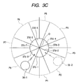
- FIG. 3C is an enlarged view schematically illustrating directional receiving patterns of the relative position detector along a horizontal surface according to the first embodiment of the present invention
- FIG. 4 is a flow chart schematically illustrating an example of operations of a control unit shown in FIG. 2 ;
- FIG. 5 is a flow chart schematically illustrating an example of operations of a control unit shown in FIG. 2 ;
- FIG. 6A is an enlarged view schematically illustrating an example of a visual configuration indicative of a relative direction on a screen of a display shown in FIG. 2 ;
- FIG. 6B is an enlarged view schematically illustrating another example of a visual configuration indicative of a relative direction on a screen of a display shown in FIG. 2 ;
- FIG. 7 is an enlarged view schematically illustrating another example of a visual configuration indicative of an undetectable information on a screen of a display shown in FIG. 2 ;
- FIG. 8 is a flow chart schematically illustrating an example of operations of a control unit shown in FIG. 2 ;
- FIG. 9 is a block diagram illustrating a schematic structure of a medical system according to a modification of the first embodiment
- FIG. 10 is a block diagram illustrating a schematic structure of a medical system according to another modification of the first embodiment
- FIG. 11A is a plan view schematically illustrating another example of a foot switch according to the first embodiment
- FIG. 11B is an enlarged perspective view schematically illustrating a relative position detector attached to the foot switch shown in FIG. 11A ;
- FIG. 11C is an enlarged view schematically illustrating directional receiving patterns of the relative position detector shown in FIG. 11B along a horizontal surface according to the first embodiment
- FIG. 12A is a plan view schematically illustrating a further example of a foot switch according to the first embodiment
- FIG. 12B is an enlarged perspective view schematically illustrating a relative position detector attached to the foot switch shown in FIG. 12A ;
- FIG. 12C is an enlarged view schematically illustrating directional receiving patterns of the relative position detector shown in FIG. 12B along a horizontal surface according to the first embodiment
- FIG. 13 is a block diagram illustrating a schematic structure of a medical system including a medical system controller according to a second embodiment of the present invention.
- FIG. 14A is a partially cross sectional view illustrating a schematic structure of a foot-switch on-off mechanism shown in FIG. 13 ;
- FIG. 14B is a partially enlarged view of the on-off mechanism shown in FIG. 14A ;
- FIG. 14C is a view for explaining operations of the on-off mechanism shown in FIG. 14A ;
- FIG. 15 is an enlarged perspective view illustrating a modification of the on-off mechanism according to the second embodiment of the present invention.
- FIG. 1 is a plan view schematically illustrating a positional relationship between elements of a medical system including a control switch detecting apparatus according to a first embodiment of the present invention in an examination room in which the medical system is located.
- FIG. 2 is a block diagram illustrating a schematic structure of the medical system shown in FIG. 1 .
- the medical system 30 related to the first embodiment is equipped with an electronic endoscopic device 33 and pieces of therapeutic treatment equipment including an ultrasonic therapeutic device 34 , an electric scalpel device 35 , and a heat scalpel device 36 . That is, the medical system 30 is designed to an endoscopic system.
- the medical system 30 is so configured that all of the devices 33 to 36 are installed in a movable gantry B.
- an operating table T is previously placed, and a patient P as a target for inspection and treatment lies on the operating table T.
- the medical system 30 (the movable gantry B) is arranged close to the operating table T.
- the medical system 30 is equipped with a foot switch 37 that allows an operator OP to specify one of the therapeutic treatment devices 34 - 36 and to instruct the identified device to control it, such as to turn it on or off.
- the foot switch 37 is laid at, for example, a desirable position for the operator OP in the examining room, such as close to the operator's feet, the operating table T, and the gantry B.
- the operator OP operates the foot switch 37 with the operator's foot at desired times to select one of the therapeutic treatment devices 34 - 36 , thereby turning the selected device on and/or off.
- the medical system 30 is provided with, as shown in FIG. 2 , a medical system controller 31 having a control unit 31 U communicable with the electronic endoscope device 33 , the ultrasonic therapeutic device 34 , the electric scalpel device 35 , the heat scalpel device 36 , and the foot switch 37 , respectively, by wire cables or radio.
- the medical system 30 is provided with a display 32 communicable with the control unit 31 U.
- the medical system 30 is provided with a position signal transmitter 38 fitted to a predetermined portion of the operator OP, for example, the ankle with a fitting member, such as a fitting band.
- the position signal transmitter 38 is operative to continuously or periodically transmit, for example, non-directional signals, such as radio signals or infrared signals, at predetermined frequencies around the transmitter 38 .
- the signals transmitted from the position signal transmitter 38 are referred to as position signals.
- the electronic endoscope device 33 is equipped with an endoscope 33 a .
- the endoscope 33 a has a fiberscope, an image pickup device, such as a CCD (Charge Coupled Device) image sensor, mounted inside the fiberscope, and an optical system mounted inside the fiberscope for focusing light irradiated from one tip end of the fiberscope on a surgical field of the patient P.
- an image pickup device such as a CCD (Charge Coupled Device) image sensor
- the electronic endoscope device 33 is provided with a light source unit 39 optically coupled to the endoscope 33 a through a light guide 39 a.
- the light source unit 39 has a lamp and a lighting control circuit for controlling the lighting of the lamp.
- the lighting control circuit turns on the lamp so that the lamp irradiates light.
- the light is guided through the light guide 39 a into the fiberscope of the endoscope 33 a.
- the electronic endoscope device 33 has an imaging processor 33 b electrically connected to the image pickup device and operative to execute predetermined image processes with respect to an image signal picked up by the image pickup device.
- the light irradiated from the fiberscope of the endoscope 33 a is focused by the optical system on the surgical field of the patient P.
- a light reflected from an area of the patient P including the surgical field is inputted to a light-sensitive surface of the image pickup device so as to be picked up thereby as the image signal.
- the image signal is inputted to the imaging processor to be subjected to the predetermined image processes thereby so that an endoscope image signal indicative of an endoscope image of the surgical field is generated.
- the endoscope image signal generated by the imaging processor 33 b is transmitted to the medical system controller 31 .
- the ultrasonic therapeutic device 34 has an ultrasonic therapeutic instrument 34 a .
- the ultrasonic therapeutic device 34 is operative to supply energy to the ultrasonic therapeutic instrument 34 a to cause it to operate.
- the operated ultrasonic therapeutic instrument 34 a generates ultrasonic waves and the generated ultrasonic waves are applied to at least a part of the surgical field, allowing the part of the surgical field to be cut away and/or to coagulate.
- the electric scalpel device 35 has an electric scalpel 35 a .
- the electric scalpel device 35 is configured to apply a high-frequency current on at least a part of the surgical field through the electric scalpel 35 a , thereby cutting off the part of the surgical field and/or coagulating it.
- the heat scalpel device 36 has a heat scalpel (not shown).
- the heat scalpel device 36 is configured to apply heat energy on at least a part of the surgical field through the heat scalpel, thereby cutting off the part of the surgical field and/or coagulating it.
- the medical system controller 31 is provided with a microphone 31 g electrically connected to the control unit 31 U and operative to input speech signals to the control unit 31 U.
- the medical system controller 31 is provided with a speaker 31 f electrically connected to the control unit 31 U and operative to output speech signals transmitted from the control unit 31 U.
- the control unit 31 U has a plurality of functional blocks including a display control block 31 a , a switch control block 31 b , a switch input block 31 c , a speech input block 31 d , and a speech output block 31 e .
- the functional blocks 31 a to 31 e are operatively connected with each other.
- the control unit 31 U is composed of a computer circuit including, for example, at least one microcomputer. At least one microcomputer is integrated with a memory in which program codes are installed through various types of storage mediums or a communication line linked to the Internet.
- the various types of storage mediums include CD-ROM (Compact Disk—Read Only Memory), DVD-ROM (Digital Versatile Disk—ROM), and the like.
- the control unit 31 U is configured to implement the respective functions 31 a to 31 e as processes in accordance with the program codes.
- the display control block 31 a has a first function of receiving the endoscope image signal supplied from the image processor 33 .
- the display control block 31 a has a second function of receiving selection information of the therapeutic treatment equipment that is obtained by the switch control block 31 b to generate a selection image signal indicative of a selection image 32 b .
- the selection image 32 b allows the operator OP to recognize one of the therapeutic treatment devices 34 - 36 that is selected by the operator OP and the operation mode of the selected one of the therapeutic treatment devices 34 - 36 .
- the display control block 31 a has a third function of superimposing the generated selection image signal on the received endoscope image signal to supply the superimposition signal to the display 32 , causing the display 32 to display the superimposition signal on its screen.
- the switch control block 31 b has a first function of receiving the selection information transmitted from the foot switch 37 or the microphone 31 g .
- the selection information preferably includes information that permits the switch control block 31 b to recognize an identifier of one device of the therapeutic treatment devices and its operating mode. As the identifier, the designation of the selected device and/or the identification codes thereof can be used.
- the switch control block 31 b has a second function of specifying one device of the therapeutic treatment devices and the operation mode that correspond to the received selection information.
- the switch control block 31 b has a third function of receiving operational instruction information, such as on/off instruction information, to send the received operational instruction information to the specified device.
- operational instruction information such as on/off instruction information
- the switch control block 31 b has a fourth function of outputting the received selection information to either the display control block 31 a or the speech output block 31 e.
- the switch input block 31 c has a function of receiving the selection information and the operational instruction information sent from the foot switch 37 to supply the received selection information and operational instruction information to the switch control block 31 b.
- At least one of the selection information, the operational instruction information, and relative position information which is generated by the operator OP as a speech, is converted into a speech signal by the microphone 31 g to be amplified thereby and the amplified speech signal is inputted to the speech input block 31 d.
- the speech input block 31 d When the amplified speech signal is inputted to the speech input block 31 d , the speech input block 31 d has a first function of receiving the inputted speech signal.
- the speech input block 31 d has a second function of specifying at least one of the selection information, the operational instruction information, and relative position information based on the received speech signal to supply it to the switch control block 31 b.
- the speech output block 31 e has a function of converting at least one of the selection information and the relative position information that is outputted from the switch control block 31 b into a speech signal recognizable by the operator OP to put the speech signal on the speaker 31 f.
- the display 32 has a first function of receiving the superimposition signal on which the endoscope image signal and the selection image signal are superimposed transmitted from the display control block 31 a .
- the display 32 has a second function of superimposing an endoscope image 32 a of the surgical field and the selection image 32 b to display the superimposed image on its screen based on the received superimposition signal.
- the display 32 executes the second function cooperatively with the control processes of the display control block 31 a based on its second function.
- the foot switch 37 has a foot-operated selection switch 37 c for selecting any one of the therapeutic treatment devices 34 - 36 . That is, the selection switch 37 c is configured to output the selection information for selecting one of the therapeutic treatment devices 34 - 36 and its operation mode to the switch control block 31 b through the switch input block 31 c.
- the foot switch 37 has a pedal output switch, in other words, foot-operated output switch 37 a for outputting the operational instruction information indicative of the turning-on or turning-off of the selected device to the switch control block 31 b through the switch input block 31 c.
- the output switch 37 a is configured to a twin-type output switch (see FIGS. 2 , 3 A and so on).
- the foot switch 37 has a relative position detector 37 d configured to receive the position signals outputted from the position signal transmitter 38 , representing a position of the position signal transmitter 38 , in other words, the operator OP.
- the selection switch 37 c attached to the foot switch 37 is, for example, a momentary push button switch. That is, the selection switch 37 c is configured to output operation information as the selection information to the switch control block 31 b through the switch input block 31 c each time the operator OP pushes the selection switch 37 c with the operator's foot.
- the switch control block 31 b is configured to select one of the therapeutic treatment devices 34 - 36 and its operation mode in all of the previously determined operation modes of each of the therapeutic treatment devices 34 - 36 each time the selection information is transmitted through the switch input block 31 c to the switch control block 31 b.
- the switch control block 31 b sequentially selects one of the combinations of the therapeutic treatment devices 34 - 36 and their operation modes.
- the combinations indicate:
- the switch control block 31 b selects both one therapeutic treatment device and its operation mode simultaneously.
- the selection information indicative of the identifier of one of the therapeutic treatment devices and its operating mode which are switchably selected every operation of the operator's selection switch 37 c is supplied from the switch control block 31 b to the display control block 31 a .
- the display control block 31 a generates the selection image signal according to the selection information supplied thereto.
- the display control block 31 a displays on the center of the screen of the display 32 with the selection image 32 b superimposed on, for example, the right corner of the screen as the operator faces.
- the selection image 32 b permits the operator OP and/or an assistant to easily recognize the currently selected therapeutic treatment device and its operating mode. Specifically, the operator OP operates to continuously turn the selection switch 37 c of the foot switch 37 while visually identifying the selection image 32 b , and when a therapeutic treatment device that the operator OP wants to use is displayed on the screen of the display 32 , the operator OP stops the on-operations. This makes easy the operator's selection of a desirable therapeutic treatment device and its operating mode.
- the output switch 37 a attached to the foot switch 37 is a momentary pedal switch. That is, the output switch 37 a has outputted the turn-on instruction information through the switch input block 31 c to the switch control block 31 b while the operator OP pushes the output switch 37 a with the operator's foot.
- the switch control block 31 b transmits, to the therapeutic treatment device selected on the selection information, the operational instruction information for causing the selected device to operate in the selected operating mode.
- the therapeutic treatment device to which the operational instruction information is transmitted operates in the selected operating mode, which allows the operator OP to use the operator's selected therapeutic treatment device operating in the operator's selected operating mode to treat the surgical field of the patient P.
- the operator OP when the operator OP produces a speech indicative of the selection information including the identifier of one of the therapeutic treatment devices 34 - 36 , which the operator OP wants to use, and the operation mode thereof, the produced speech corresponding to the selection information is converted into electric signals by the microphone 31 g and amplified thereby.
- the amplified electric signals are supplied to the speech input block 31 d as speech signals.
- the speech input block 31 g receives the supplied speech signals and analyzes the received speech signals to detect the selection information, that is, the identifier of the selected device and its operating mode.
- the speech input block 31 g supplies the detected selection information to the switch control block 31 b.
- the switch control block 31 b performs the selection processes of one of the therapeutic treatment devices and its operating mode based on the supplied selection information in the same manner as the selection information supplied from the foot switch 37 .
- the operational instruction information such as turning-on or turning-off information, of the therapeutic treatment device selected according to the speech inputted from the microphone 31 g is inputted from the operator OP through the output switch 37 a of the foot switch 37 to the switch control block 31 b .
- the switch control block 31 b transmits the operational instruction information to the selected device so that the selected device is controlled based on the operational instruction information.
- the relative position detector 37 d attached to the foot switch 37 is provided with a metal antenna body having a substantially circular plate as a whole.
- the antenna body is preferably radially divided into a number of, such as 8 , equal pieces from the center O thereof.
- the pieces of the metal antenna body serve as receiving antennas 37 d - 1 , 37 d - 2 , . . . , 37 d - 8 , which have individual receiving directivities with respect to the position signals transmitted from the position signal transmitter 38 , respectively.
- each of the receiving antennas 37 d - 1 to 37 d - 8 has a substantially fan-like shape in its cross section parallel to the radial direction.
- Each of the receiving antennas 37 d - 1 to 37 d - 8 has a receiving unit operative to receive the position signals each with the predetermined frequency transmitted from the position signal transmitter 38 .
- Each of the receiving antennas 37 d - 1 to 37 d - 8 also has an amplifier operative to amplify the position signals received by the receiving unit, and an output unit operative to output the amplified position signals.
- Each of the receiving antennas 37 d - 1 to 37 d - 8 has a circular arc end surface, and each of directional receiving patterns P- 1 to P- 8 has a high sensitivity to some of the position signals transmitted from an area radially extending from the circular arc end surface.
- FIG. 3C shows the directional receiving patterns P- 1 to P- 8 around the relative position detector 37 d along a horizontal surface, such as a floor surface of the examining room on which the operator OP is movable.
- Each of the directional receiving patterns P- 1 to P- 8 along a vertical direction orthogonal to the horizontal direction has a high sensitivity to some of the position signals positioned in a predetermined range centered at each of the circular arc end surface and expanding along the vertical direction.
- Each of the directional receiving patterns P- 1 to P- 8 of each of the receiving antennas 37 d - 1 to 37 d - 8 allows the relative position detector 37 d to detect the position signals around the relative position detector 37 d with great sensitivity.
- the receiving antennas 37 d - 1 to 37 d - 8 are individually communicable with the control unit 31 U of the medical system controller 31 by wire cables or radio.
- the receiving antennas 37 d - 1 to 37 d - 8 are respectively driven in response to driving signals transmitted from the switch input block 31 c to operate to detect the position signals.
- the receiving antennas 37 d - 1 to 37 d - 8 further operate to individually transmit the detected signals through the switch input block 31 c to the switch control block 31 b .
- the receiving antennas 37 d - 1 to 37 d - 8 may be independently driven at all times or in a cycle, to detect the position signals. In this modification, the receiving antennas 37 d - 1 to 37 d - 8 operate to individually independently transmit the detected position signals through the switch input block 31 c to the switch control block 31 b.
- the switch control block 31 b has a fifth function of determining information indicative of a relative positional relationship between the foot switch 37 and the operator OP, in other words, between the position signal transmitter 38 and the relative position detector 37 d , according to the position signals detected by the receiving antennas 377 d - 1 to 37 d - 8 .
- the information determined based on the fifth function of the switch control block 31 b is referred to as “relative position information” hereinafter.
- the relative position information between the position signal transmitter 38 and the relative position detector 37 d preferably includes a direction of the position signal transmitter 38 with respect to the relative position detector 37 d and/or a distance between the position signal transmitter 38 and the relative position detector 37 d.
- the switch control block 31 b compares the intensities of the position signals of the respective receiving antennas 37 d - 1 and 37 d - 8 with one another. As a result of the comparison, the switch control block 31 b specifies one of the receiving antennas 37 d - 1 to 37 d - 8 , which receives the position signal with the highest intensity in all of the receiving antennas.
- the switch control block 31 b determines the direction of the specified receiving antenna with respect to the center O of the relative position detector 37 d as a direction of the position signal transmitter 38 , in other words, a direction of the operator OP.
- the position signal transmitter 38 fitted to the operator OP is located in, for example, the directional receiving pattern P- 8 of the receiving antenna 37 d - 8 .
- a reference numeral of 38 - 1 is assigned to the position signal transmitter 38 .
- the position signal transmitted from the position signal transmitter 38 - 1 is received by the receiving antennas 37 d - 1 to 37 d - 8 of the relative position detector 37 d , respectively.
- the intensities of the received position signals received by the respective receiving antennas 37 d - 1 to 37 d - 8 are compared with one another by the switch control block 31 b , thereby specifying that the receiving antenna 37 d - 8 detects the receiving signal having the highest intensity in all of the receiving antennas 37 d - 1 to 37 d - 8 .
- the switch control block 31 b recognizes that the foot switch 37 is located in the diagonally upper right direction from the position signal transmitter 38 - 1 (the operator OP).
- the position signal transmitter 38 fitted to the operator OP is located in, for example, the directional receiving pattern P- 2 of the receiving antenna 37 d - 2 .
- a reference numeral of 38 - 2 is assigned to the position signal transmitter 38 .
- the position signal transmitted from the position signal transmitter 38 - 2 is received by the receiving antennas 37 d - 1 to 37 d - 8 of the relative position detector 37 d , respectively.
- the intensities of the position signals received by the respective receiving antennas 37 d - 1 to 37 d - 8 are compared with one another by the switch control block 31 b , thereby determining that the receiving antenna 37 d - 2 detects the receiving signal having the highest intensity in all of the receiving antennas 37 d - 1 to 37 d - 8 .
- the switch control block 31 b recognizes that the foot switch 37 is located in the diagonally upper left direction from the position signal transmitter 38 - 2 (the operator OP).
- the receiving antenna 37 d - 1 receives the position signal having the highest intensity in all of the receiving antennas 37 d - 1 to 37 d - 8 .
- the switch control block 31 b compares the intensity of the received position signal by the receiving antenna 37 d - 1 with a reference value indicative of a reference intensity that has a predetermined relationship with respect to a corresponding given distance.
- the switch block 31 b estimates the distance between the position signal transmitter 38 and the relative position detector 37 d based on the comparison result.
- the display control block 31 a When the relative position information between the foot switch 37 and the operator OP (the position signal transmitter 38 and the relative position detector 37 d ) is transmitted from the switch control block 31 b , the display control block 31 a has a third function of receiving the transmitted relative position information.
- the display control block 31 a as the third function, performs control processes to convert the received relative position information into a visual configuration that the operator OP can visually recognize, thereby displaying the converted visual configuration of the received relative position information on the display's screen in collaboration with a third function of the display 32 .
- the operator OP investigates the endoscope image 32 a displayed on the display's screen to closely observe the surgical field of the patient P. This allows the operator OP to determine one of the therapeutic treatment devices and its operating mode (for example, the ultrasonic therapeutic device 34 and 70% output as the operating mode), which match the state of the surgical field.
- the therapeutic treatment devices and its operating mode for example, the ultrasonic therapeutic device 34 and 70% output as the operating mode
- the operator OP operates to turn the selection switch 37 c on one or more times for selecting and specifying the ultrasonic therapeutic device 34 and its operating mode of 70% output.
- the above processes of the selection switch 37 c , the switch control block 31 b , and the display control block 31 a are performed. This results in that the selection images 32 b representing the selected therapeutic treatment devices and their operating modes, respectively, are switchably displayed on the screen of the display 32 every operation of the operator's selection switch 37 c.
- the operator OP watches the switchably displayed selection images 32 b .
- the operator visually recognizes that the operator's desired selection image 32 b representing the ultrasonic therapeutic device 34 and its operating mode of 70% output is displayed on the display's screen, the operator OP operates to turn the output switch 37 a of the foot switch 37 on and to keep the on state of the output switch 37 a.
- This turning-on operation and keeping operation of the output switch 37 a permit the output switch 37 a , the switch control block 31 b and the like to transmit, to the ultrasonic therapeutic treatment device 34 , the operational instruction information for causing the selected ultrasonic therapeutic treatment device 34 to operate in the selected operating mode of 70% output.
- the ultrasonic therapeutic treatment device 34 receives the transmitted operational instruction information to be driven in the operating mode of 70% output based of the received operational instruction information.
- the operator OP uses the operator's specified therapeutic treatment device driven in the operator's specified operating mode to treat the surgical field of the patient P.
- the selection image 32 b representing the specified therapeutic treatment device and its operating mode is displayed on the screen of the display 32 . This allows the operator OP to visually recognize the operator's selected therapeutic treatment device and the operator's selected operating mode, making it possible to check the selected device and the selected operating mode at any time during the turning-on of the output switch 37 a.
- the operator OP can produce a speech indicative of the identifier of the specified device, for example, the identifier of the ultrasonic therapeutic treatment device 34 and its operating mode of, for example, 70% output.
- the produced speech indicative of the selection information is processed by the microphone 31 g and the speech input block 31 d set forth above so as to be transmitted to the switch control block 31 b and the display control block 31 a , respectively.
- the selection image 32 b representing the specified therapeutic treatment device and its specified operating mode by the speech input is displayed on the screen of the display 32 .
- the turning-on operation and keeping operation of the output switch 37 a allow the specified therapeutic treatment device, such as ultrasonic therapeutic treatment device 34 , to be driven in the specified operating mode, such as 70% output.
- the operator OP operates to turn the on-state output switch 37 a off.
- This turning-off operation of the output switch 37 a causes the switch control block 31 b to transmit the turning-off instruction information to the specified ultrasonic therapeutic treatment device 34 , making it possible to turn the operation of the ultrasonic therapeutic treatment device 34 off.
- the medical system 30 allows the operator OP to easily and rapidly specify, with the use of the foot switch 37 and/or the microphone 31 g , one of the therapeutic treatment devices and its operating mode.
- the specified therapeutic treatment device and its operating mode match the state of the patient's surgical field while visually investigating the endoscope image 32 a of the surgical field.
- the medical system 30 according to the first embodiment allows the operator OP to easily and rapidly give the operational instruction information (turning-on or turning-off instruction information), with the use of the foot switch 37 and/or the microphone 31 g , to the specified therapeutic treatment device.
- the operator OP when determining one of the therapeutic treatment devices and its operating mode that match the surgical field of the patient P, the operator OP tries to operate the foot switch 37 to specify the determined therapeutic treatment device and its operating mode. In particular, the operator OP tries to push the operator's foot down on the selection switch 37 c.
- the operator OP when the operator OP does not find the foot switch 37 , the operator OP produces a speech indicative of a keyword, such as “foot switch” for providing an operational instruction to the control unit 31 U through the microphone 31 g .
- the aim of the operational instruction is to cause the control unit 31 U to detect the position of the foot switch 37 .
- the produced keyword “foot switch” is inputted to the microphone 31 g to be converted into a speech signal.
- the speech signal is amplified by the microphone 31 g to be supplied to the speech input block 31 d.
- the speech input block 31 d receives the supplied speech signal to perform speech recognition based on the speech signal, thereby recognizing the keyword of “foot switch”.
- the speech input block 31 d provides the speech recognition information indicative of the keyword of “foot switch” to the switch control block 31 b.
- the switch control block 31 b operates in a foot switch's position searching mode in response to receiving the speech recognition information indicative of “foot switch”.
- the switch control block 31 b is adapted to control the operation of the relative position detector 37 d through the switch input block 31 c , thereby causing the relative position detector 37 d to receive the position signals transmitted from the position signal transmitter 38 .
- the switch control block 31 b is also adapted to detect the relative positional relationship between the position signal transmitter 38 and the relative position detector 37 d based on the received position signals.
- the operations of the control unit 31 U in the foot switch's position searching mode will be described with reference to FIG. 4 .
- the flowchart shown in FIG. 4 represents processes of the functional blocks 31 a to 31 e of the control unit 31 U in accordance with the program codes installed in the control unit 31 U.
- the operator OP when the operator OP produces the speech indicative of the keyword of “foot switch” for searching the position of the foot switch 37 , the produced speech of “foot switch” is converted by the microphone 31 g into the speech signal so as to be amplified thereby.
- the amplified speech signal is supplied to the control unit 31 U.
- the speech input block 31 d of the control unit 31 U receives the supplied speech signal in step S 1 of FIG. 4 to perform speech recognition based on the speech signal, thereby recognizing the keyword of “foot switch” in step S 2 .
- step S 3 the switch control block 31 b of the control unit 31 U controls the operations of all of the receiving antennas 37 d - 1 to 37 d - 8 of the relative position detector 37 d through the speech input block 31 c in response to receiving the speech-recognized keyword of “foot switch”.
- the control process causes the receiving antennas 37 d - 1 to 37 d - 8 to receive the position signals transmitted from the position signal transmitter 38 , respectively.
- the switch control block 31 b determines whether the position signals are transmitted from more than a predetermined number of receiving antennas out of the receiving antennas 37 d - 1 to 37 d - 8 . In other words, the switch control block 31 b determines whether the block 31 b can obtain the relative position information between the position signal transmitter 38 and the relative position detector 37 d in step S 4 .
- step S 4 When the position signals are transmitted from more than the predetermined number of receiving antennas out of the receiving antennas 37 d - 1 to 37 d - 8 , the determination in step S 4 is YES, so that the switch control block 31 b fetches the position signals transmitted from the receiving antennas 37 d - 1 to 37 d - 8 through the switch input block 31 c in step S 5 .
- the switch control block 31 b determines the relative position information between the position signal transmitter 38 and the relative position detector 37 d based on the fetched position signals in step S 6 .
- the switch control block 31 b receives the position signals transmitted from, for example, all of the receiving antennas 37 d - 1 to 37 d - 8 through the switch input block 31 c in step S 6 a 1 of FIG. 5 .
- the switch control block 31 b compares the intensities of the position signals corresponding to the receiving antennas 37 d - 1 to 37 d - 8 with one another to specify one of the receiving antennas 37 d - 1 to 37 d - 8 , which receives the position signal having the highest intensity in other receiving antennas in step S 6 a 2 .
- the switch control block 31 b determines a relative direction of the center O of the relative position detector 37 d with respect to the specified receiving antenna to obtain a relative direction of the foot switch 37 with respect to the position signal transmitter 38 (the operator OP) based on the determined relative direction of the center O of the relative position detector 37 d as the relative position information in step S 6 a 3 .
- the switch control block 31 b recognizes that the relative direction of the foot switch 37 with respect to the position signal transmitter 38 (operator OP) is a diagonally lower left direction.
- the switch control block 31 b supplies the obtained relative direction as the relative position information to the display control block 31 a and the speech output block 31 e , respectively, in step S 7 .
- the display control block 31 a converts the supplied relative position as the relative position information into a visual configuration that the operator OP can visually recognize, such as an arrow marker or character data indicative of the relative direction.
- the display control block 31 a superimposes the converted visual configuration of the relative direction on the selection image 32 b to display them together on the screen, or displays the converted visual configuration of the relative direction on the screen so as to be close to the selection image 32 b displayed thereon in step S 8 .
- the relative direction between the position signal transmitter 38 and the relative position detector 37 d of the foot switch 37 represents that “the foot switch 37 is in the diagonally upper right direction from the position signal transmitter 38 (the operator OP)”.
- the processes of the display control block 31 a provide that a transparent arrow marker M 1 indicative of the relative direction (the diagonally upper right direction) is superimposed on the selection image 32 b displayed on the screen (see FIG. 6A ).
- the processes of the display control block 31 a provide that a number of, for example, eight inward arrow markers M 11 to M 18 , which are lightable, respectively, are displayed on the screen around the selection image 32 b at substantially constant intervals.
- the processes of the display control block 31 a allow one of the arrow markers M 11 to M 18 , which corresponds to the “diagonally upper right”, such as the arrow marker M 11 , to be turned on (see FIG. 6B ).
- the lighted marker M 11 is illustrated to be blacked out.
- the processes of the display control block 31 a allow one of the arrow markers M 11 to M 18 , which corresponds to the “left direction”, such as the arrow marker M 14 , to be turned on (see FIG. 6B ).
- the lighted marker M 14 is illustrated by broken lines.
- the control of the visual configuration of one arrow marker that represents the relative position information between the position signal transmitter 38 and the relative position detector 37 d is not limited to the control of lighting of the one arrow marker. That is, controlling the visual configuration of one arrow marker that represents the relative position information between the position signal transmitter 38 and the relative position detector 37 d to allow the one arrow marker to be visually identified in all of the arrow markers.
- the speech output block 31 e converts the relative direction as the relative position information supplied from the switch control block 31 b into speech information recognizable by the operator OP, thereby outputting the converted speech information through the speaker 31 f in step S 9 .
- the relative direction of the foot switch 37 (the relative position detector 37 d ) with respect to the position signal transmitter 38 indicates that “the foot switch 37 is in the diagonally upper right direction from the position signal transmitter 38 (the operator OP)”.
- the processes of the speech output block 31 e allow a speech indicative of the relative direction of the foot switch 37 , such as “the foot switch is located in the diagonally upper right direction”, to be outputted from the speaker 31 f.
- the determination in step S 4 is NO.
- the switch control block 31 b generates undetectable information of relative positional relationship representing that the relative positional relationship between the position signal transmitter 38 and the relative position detector 37 d (foot switch 37 ) is undetectable based on the position signals.
- the switch control block 31 b supplies the generated undetectable information to the display control block 31 a and the speech output block 31 e , respectively, in step S 10 .
- the display control block 31 a converts the contents of the supplied undetectable information from the switch control block 31 b into a visual configuration that the operator OP can visually recognize, such as an arrow marker or character data indicative of the undetectable information.
- the display control block 31 a superimposes the converted visual configuration of the undetectable information on the selection image 32 b to display them together on the screen, or displays the converted visual configuration of the undetectable information on the screen so as to be close to the selection image 32 b displayed thereon in step S 11 .
- the processes of the display control block 31 a allow all of the arrow markers M 11 to M 18 displayed on the screen around the selection image 32 b at substantially constant intervals to blink, respectively.
- the control of the visual configuration of at least one arrow marker that represents the undetectable information of relative positional relationship between the position signal transmitter 38 and the relative position detector 37 d is not limited to the blink of all of the arrow markers.
- controlling the visual configuration of at least one arrow marker that represents the undetectable information of relative positional relationship between the position signal transmitter 38 and the relative position detector 37 d allows the operator OP to recognize that the relative positional relationship between the position signal transmitter 38 and the relative position detector 37 d (foot switch 37 ) is undetectable based on the position signals.
- the speech output block 31 e converts the undetectable information supplied from the switch control block 31 b into speech information recognizable by the operator OP, thereby outputting the converted speech information through the speaker 31 f in step S 12 .
- the processes of the speech output block 31 e allow a speech indicative of the undetectable information of the foot switch 37 , such as “the foot switch is not detected”, to be outputted from the speaker 31 f.
- the processes of the switch control block 31 b in step S 6 shown in FIG. 5 determine the relative direction as the relative position information.
- detection of a relative distance between the relative position detector 37 d (foot switch 37 ) and the position signal transmitter 38 (operator OP) becomes possible.
- the switch control block 31 b executes the processes in step S 6 a 1 and S 6 a 2 shown in FIG. 5 , respectively, to identify one receiving antenna corresponding to the position signal having the highest intensity.
- the switch control block 31 b compares the intensity of the receiving signal received by the identified receiving antenna with the reference value indicative of the reference intensity that has the predetermined relationship with respect to the corresponding given distance.
- the switch block 31 b estimates the relative distance of the foot switch 37 (the relative position detector 37 d ) with respect to the position signal transmitter 38 based on the comparison result in step S 6 b 1 of FIG. 8 .
- the switch control block 31 b determines whether the estimated relative distance is within a predetermined distance, such as 1 m centered with respect to the operator OP in step S 6 b 2 .
- step S 6 b 2 When the estimated relative distance is within the predetermined distance, the determination in step S 6 b 2 is YES, so that the switch control block 31 b determines a relative direction of the center O of the relative position detector 37 d with respect to the specified receiving antenna.
- the switch control block 31 b obtains a relative direction of the foot switch 37 with respect to the position signal transmitter 38 (the operator OP) based on the determined relative direction of the center O of the relative position detector 37 d .
- the switch control block 31 b determines the relative position information representing that the relative distance is within the predetermined distance in the obtained relative direction in step S 6 b 3 .
- step S 6 b 2 determines a relative direction of the center O of the relative position detector 37 d with respect to the specified receiving antenna.
- the switch control block 31 b determines a relative direction of the foot switch 37 with respect to the position signal transmitter 38 (the operator OP) based on the determined relative direction of the center O of the relative position detector 37 d .
- the switch control block 31 b determines the relative position information representing that the relative distance exceeds the predetermined distance in the obtained relative direction in step S 6 b 4 .
- the switch control block 31 b supplies the obtained relative position information to the display control block 31 a and the speech output block 31 e , respectively (see step S 7 of FIG. 4 ).
- the display control block 31 a converts the supplied relative position information into a visual configuration visually recognizable by the operator OP, such as an arrow marker or character data.
- the display control block 31 a superimposes the converted visual configuration of the relative position information on the selection image 32 b to display them together on the screen, or displays the converted visual configuration on the screen so as to be close to the selection image 32 b displayed thereon (see step S 8 of FIG. 4 ).
- the display control block 31 a displays the transparent arrow marker M 1 indicative of the relative direction (the diagonally upper right direction) on the selection image 32 b (see FIG. 6A ) or close to the selection image 32 b (see FIG. 6B ) so that the size of the arrow marker M 1 becomes a predetermined first size representing that the relative distance is within the predetermined distance.
- the arrow marker is displayed so that its lateral width gets to be thick and its longitudinal length gets to be short.
- the speech output block 31 e converts the relative position information supplied from the switch control block 31 b into speech information recognizable by the operator OP, thereby outputting the converted speech information through the speaker 31 f (see step S 9 of FIG. 4 ).
- the relative position information of the foot switch 37 (the relative position detector 37 d ) with respect to the position signal transmitter 38 indicates that “the foot switch 37 is in the diagonally upper right direction from the position signal transmitter 38 (the operator OP), and the relative distance is within the predetermined distance”.
- the processes of the speech output block 31 e allow a speech indicative of the relative position information of the foot switch 37 , such as “the foot switch is located in the diagonally upper right direction and close to the operator”, to be outputted from the speaker 31 f.
- the relative position information between the foot switch 37 (the relative position detector 37 d ) and the position signal transmitter 38 indicates that “the foot switch 37 is in the diagonally upper right direction from the position signal transmitter 38 (the operator OP), and the relative distance exceeds the predetermined distance”.
- the display control block 31 a displays the transparent arrow marker M 1 indicative of the relative direction (the diagonally upper right direction) on the selection image 32 b (see FIG. 6A ) or close to the selection image 32 b (see FIG. 6B ) so that the size of the arrow marker M 1 becomes a predetermined second size representing that the relative distance is out of the range of the predetermined distance around the operator OP.
- the arrow marker is displayed so that its lateral width gets to be thin and its longitudinal length gets to be long.
- the speech output block 31 e converts the relative position information supplied from the switch control block 31 b into speech information recognizable by the operator OP, thereby outputting the speech information through the speaker (see step S 9 ).
- the relative position information of the foot switch 37 (the relative position detector 37 d ) with respect to the position signal transmitter 38 indicates that “the foot switch 37 is in the diagonally upper right direction from the position signal transmitter 38 (the operator OP) and is out of the range of the predetermined distance”.
- the processes of the speech output block 31 e allow a speech indicative of the relative position information of the foot switch 37 , such as “the foot switch is located in the diagonally upper right direction at a distance therefrom”, to be outputted from the speaker 31 f.
- the operator OP recognizes the relative position information displayed on the screen of the display 32 and/or outputted as a speech from the speaker 31 f.
- This feature allows, even if the operator OP does not find the position of the foot switch 37 , the operator OP to easily search and find the position of the foot switch 37 based on the recognized relative position information including at least one of the relative direction and the relative distance of the foot switch 37 .
- the medical system 30 of the first embodiment allows the operator OP to recognize the relative position information while visually investigating the surgical field through the endoscope image 32 a displayed on the screen of the display 32 .
- This feature permits the operator OP to move the operator's foot according to the relative position information without turning the operator's eyes from the surgical field and diverting the operator's interest therefrom, making it possible to smoothly detect the foot switch 37 .
- the medical system 30 of the first embodiment permits the operator OP to visually recognize the selection image 32 b displayed on the screen of the display 32 to recognize which device and which operating mode are selected at any given time.
- the relative direction between the foot switch 37 and the position signal transmitter 38 (operator OP) or both the relative direction and the relative distance therebetween are obtained as the relative position information, and the obtained relative position information is notified to the operator OP.
- the only relative direction may be notified to the operator OP.
- the position signal transmitter 38 is operative to continuously or periodically transmit the position signals, but the present invention is not limited to the structure.
- the receiving antennas 37 d - 1 to 37 d - 8 of the relative position detector 37 d can be configured to receiving and transmitting antennas 37 d - 1 a to 37 d - 8 a .
- Each of the receiving and transmitting antennas 37 d - 1 a to 37 d - 8 a has a directional transmitting pattern corresponding to each of the directional receiving patterns P- 1 to P- 8 .
- the receiving and transmitting antennas 37 d - 1 a to 37 d - 8 a are operative to transmit drive signals based on the directional transmitting patterns, respectively.
- the switch control block 31 b controls the receiving and transmitting antennas 37 d - 1 a to 37 d - 8 a through the switch input block 31 c , thereby causing all of the receiving and transmitting antennas 37 d - 1 a to 37 d - 8 a to transmit the drive signals, respectively.
- the position signal transmitter 38 when the position signal transmitter 38 is located in the directional pattern P 1 , the position signal transmitter 38 receives the transmitted drive signal transmitted from the receiving and transmitting antenna 37 d - 1 a to transmit the position signals.
- the receiving and transmitting antennas 37 d - 1 a to 37 d - 8 a receive the position signal transmitted from the position signal transmitter 38 so that the determination process of the switch control block 31 b in step S 4 is YES, making it possible for the switch control block 31 b to shift to the processes after the processes in step S 4 .
- a time interval from the transmitting timing of the drive signal from at least one of the transmitting and receiving antennas 37 d - 1 a to 37 d - 8 a to the receiving timing of the position signal allows the relative distance between the position signal transmitter 38 and at least one of the transmitting and receiving antennas 37 d - 1 a and 37 d - 8 a to be determined.
- the switch control block 31 b of the control unit 31 U executes the processes of obtaining the relative position information
- the present invention is not limited to the structure. That is, a processing unit having functions that are substantially identical with those of the switch control block 31 b may be installed in the foot switch 37 , and the processing unit may execute the processes of obtaining the relative position information between the foot switch 37 and the operator OP.
- the position signal transmitter 38 may be installed in the foot switch 37 , and the relative position detector 37 d may be separated from the foot switch 37 to be fitted to the operator OP.
- the position signal transmitter 38 attached to the foot switch 37 may be operative to transmit the position signals based on the drive signals transmitted from the switch input block 31 c.
- the relative position detector 37 d and the foot switch 37 may be integrated with each other, but the present invention is not limited to the structure.
- a relative position detector 37 da is provided independently from a foot switch 37 - 1 .
- the relative position detector 37 da may be detachable from the foot switch 37 - 1 .
- the foot switch 37 - 1 has a position signal transmitter 37 e having position signal transmitting functions that are substantially identical with those of the position signal transmitter 38 .
- each of the receiving antennas 37 d - 1 to 37 d - 8 of the relative position detector 37 da receives position signals transmitted from each of the position signal transmitter 37 e and the position signal transmitter 38 fitted to the operator OP.
- Each of the receiving antennas 37 d - 1 to 37 d - 8 supplies the received position signals to the switch input block 31 c.
- the switch control block 31 b determines the relative position information of the foot switch 37 - 1 with respect to the position signal transmitter 37 e based on the position signals transmitted from the foot switch 37 - 1 .
- the switch control block 31 b also determines the relative position information of the position signal transmitter 38 (the operator OP) with respect to the relative position detector 37 da.
- the switch control block 31 b determines the relative position information between the foot switch 37 - 1 and the operator OP according to the relative position information between the foot switch 37 - 1 and the relative position detector 37 da and that between the operator OP and the relative position detector 37 da .
- one relative position detector 37 d is attached to the foot switch 37 , but the present invention is not limited to the structure.
- a plurality of, for example, two relative position detectors 37 d 1 and 37 d 2 are attached at predetermined different positions of a foot switch 37 - 2 , respectively.
- the position signals transmitted from the position signal transmitter 38 are received to the relative position detectors 37 d 1 and 37 d 2 , respectively.
- the position signals are supplied from the relative position detectors 37 d 1 and 37 d 2 to the switch control block 31 b through the switch input block 31 c , respectively.
- the switch control block 31 b determines the relative position information between the foot switch 37 - 2 and the position signal transmitter 38 by triangulation based on the position signals supplied from the relative position detectors 37 d 1 and 37 d 2 . This causes the accuracy of the determined relative position information to be further improved in addition to the effects provided by the medical system 30 shown in FIG. 2 .
- the relative position detector 37 d having the structure shown in FIGS. 3A to 3C is used as a device for determining information indicative of a relative positional relationship between the foot switch 37 and the operator OP, but the present invention is not limited to the structure.
- Various types of devices each operative to determine information indicative of a relative positional relationship between the foot switch 37 and the operator OP may be applied in place of the relative position detector 37 d.
- a relative position detector 37 db attached to a foot switch 37 - 3 shown in FIGS. 11A to 11C is provided with a metal receiving antenna 37 db - 10 having a substantially fan-like shape in its cross section parallel to the radial direction.
- the receiving antenna 37 db - 10 has a receiving directivity in a predetermined direction parallel to, for example, a horizontal surface, such as the floor surface of the examining room.
- the fan-like shaped receiving antenna 37 db - 10 has one circular-arc end surface 37 db - 10 a and the other root end portion.
- the relative position detector 37 db is also provided with a metal supporting pole SP supporting at its one end the root end portion of the receiving antenna 37 db - 10 , and a rotating mechanism 37 db - 11 supporting the other end of the supporting rod SP.
- the rotating mechanism 37 db - 11 causes the supporting pole SP to rotate so that the receiving directivity of the receiving antenna 37 db - 10 rotates along the horizontal surface within the range of, for example, 360 degrees.
- the receiving antenna 37 db - 10 has a receiving unit operative to receive the position signals each with the predetermined frequency transmitted from the position signal transmitter 38 .
- the receiving antenna 37 db - 10 also has an amplifier operative to amplify the position signals received by the receiving unit, and an output unit operative to output the amplified position signals.
- the receiving antenna 37 db - 10 has a three-dimensional directional receiving pattern P- 10 along the horizontal direction and vertical direction.
- the directional receiving pattern P- 10 has a high sensitivity to some of the position signals transmitted from an area radially extending from the circular-arc end surface 37 db - 10 a of the receiving antenna 37 db - 10 .
- the directional receiving pattern P- 10 rotating 360 degrees allows the receiving antenna 37 db - 10 to receive the position signals around the foot switch 37 - 3 .
- the rotating mechanism 37 db - 11 is provided with a comparing unit CP 1 operative to hold the position signals outputted from the output unit so as to link the held position signals to corresponding rotation angles (rotation directions) of the receiving antenna 37 db - 10 from a predetermined reference position, respectively.
- the comparing unit CP 1 is also operative to compare the intensities of the held position signals with one another.
- the comparing unit CP- 1 is communicable with the control unit 31 U of the medical system controller 31 by wire cables or radio.
- the rotating mechanism 37 db - 11 controls the supporting pole PS based on the drive signal transmitted from the switch input block 31 c of the control unit 31 U so as to rotate the supporting pole SP.
- the rotation of the supporting pole SP allows the receiving antenna 37 db - 10 to rotate together with the supporting pole SP.
- the position signals transmitted from the position signal transmitter 38 are received by the rotating receiving antenna 37 db - 10 for each rotation angle.
- the position signals received by the receiving antenna 37 db - 10 are supplied to the comparing unit CP- 11 .
- the intensities of the position signals corresponding to the individual rotation angles of the receiving antenna 37 db - 10 , respectively, are compared with one another.
- the result of comparison identifies one of the rotation angles at which the position signal having the highest intensity in all of the rotation angles is received by the receiving antenna 37 db - 10 .
- the identified rotation angle corresponding to a direction with respect to the supporting pole SP provides a relative direction of the position signal transmitter 38 , in other words, a relative direction of the operator OP, with respect to the relative position detector 37 db.
- FIG. 11C it is supposed that, when the receiving antenna 37 db - 10 is rotated from the reference position at an angle of ⁇ 1, the position signal transmitter 38 is located in the directional receiving pattern P- 10 of the receiving antenna 37 db - 10 (see a reference numeral of 38 - 1 assigned to the position signal transmitter 38 in FIG. 11C ).
- the position signals transmitted from the position signal transmitter 38 - 1 are received by the rotating receiving antenna 37 db - 10 for each rotation angle.
- the intensities of the position signals corresponding to the individual rotation angles of the receiving antenna 37 db - 10 , respectively, are compared with one another.
- the result of comparison identifies the rotating angle of ⁇ 1 at which the position signal having the highest intensity in all of the rotation angles is received by the receiving antenna 37 db - 10 .
- the comparing unit CP 1 recognizes that the position signal transmitter 38 - 1 is located in a lower left direction in FIG. 11C corresponding to the identified rotation angle of ⁇ 1 with respect to the supporting pole SP.
- the comparing unit CP 1 recognizes that the foot switch 37 - 3 is located in an upper right direction in FIG. 11C corresponding to the opposite direction of the lower left direction determined by the identified rotation angle of ⁇ 1 with respect to the supporting pole SP.
- the direction of the position signal transmitter 38 - 2 can be recognized in the same way as the position signal transmitter 38 - 1 .
- the comparing unit CP 1 recognizes that the position signal transmitter 38 - 2 is located in a lower right direction in FIG. 11C corresponding to the identified rotation angle of ⁇ 2 with respect to the supporting pole SP. In other words, the comparing unit CP 1 recognizes that the foot switch 37 - 3 is located in an upper left direction in FIG. 11C corresponding to the opposite direction of the lower right direction determined by the identified rotation angle of ⁇ 2 with respect to the supporting pole SP.
- the comparing unit CP 1 compares the intensity of the receiving signal received by the receiving antenna 37 db - 10 at the identified rotation angle with the reference value indicative of the reference intensity that has the predetermined relationship with respect to the corresponding given distance.
- the comparing unit CP 1 estimates the relative distance of the foot switch 37 - 3 (the relative position detector 37 db ) with respect to the position signal transmitter 38 based on the comparison result.
- the comparing unit CP 1 executes the processes of obtaining the relative position information, such as the relative direction and/or the relative distance, but the present invention is not limited to the structure. That is, the switch control block 31 b of the control unit 31 U may execute the processes of obtaining the relative position information between the foot switch 37 and the operator OP.
- a relative position detector capable of detecting the optical position signals to convert them into electric signals is needed.
- a relative position detector 37 dc attached to a foot switch 37 - 4 shown in FIGS. 12A to 12B is provided with a light detecting element 37 dc - 12 having a substantially fan-like shape in its cross section parallel to the radial direction.
- the light detecting element 37 dc - 12 has a receiving directivity in a predetermined direction parallel to, for example, a horizontal surface, such as the floor surface of the examining room.
- the fan-like shaped light detecting element 37 dc - 12 has one circular-arc end surface 37 db - 12 a and the other root end portion.
- the relative position detector 37 dc is also provided with a supporting pole SP 1 supporting at its one end the root end portion of the light detecting element 37 dc - 12 , and a rotating mechanism 37 dc - 11 supporting the other end of the supporting rod SP 1 .
- the rotating mechanism 37 dc - 11 causes the supporting pole SP 1 to rotate so that the receiving directivity of the receiving antenna 37 dc - 12 rotates along the horizontal surface within the range of, for example, 360 degrees.
- the light detecting element 37 dc - 12 has a receiving unit operative to receive the optical position signals transmitted from a position signal transmitter 38 a capable of transmitting the optical position signals as the position signals.
- the light detecting element 37 dc - 12 also has an amplifier operative to amplify the optical position signals received by the receiving unit, and an output unit operative to convert the amplified optical position signals into electric position signals to output them.
- the amplification may be executed after the conversion of the optical position signals into the electric position signals.
- the light detecting element 37 dc - 12 has a three-dimensional directional receiving pattern P- 12 along the horizontal direction and vertical direction.
- the directional receiving pattern P- 12 has a high sensitivity to some of the optical position signals transmitted from an area radially extending from the circular-arc end surface 37 dc - 12 a of the light detecting element 37 dc - 12 .
- the directional receiving pattern P- 12 rotating 360 degrees allows the light detecting element 37 dc - 12 to receive the optical position signals around the foot switch 37 - 4 .
- the rotating mechanism 37 dc - 11 is provided with a comparing unit CP 2 operative to hold the optical position signals outputted from the output unit so as to link the held optical position signals to corresponding rotation angles (rotation directions) of the light detecting element 37 dc - 12 from a predetermined reference position, respectively.
- the comparing unit CP 2 is also operative to compare the intensities of the held optical position signals with one another.
- the comparing unit CP- 12 is communicable with the control unit 31 U of the medical system controller 31 by wire cables or radio.
- the rotating mechanism 37 dc - 12 controls the supporting pole PS 1 based on the drive signal transmitted from the switch input block 31 c of the control unit 31 U so as to rotate the supporting pole SP 1 .
- the rotation of the supporting pole SP 1 allows the light detecting element 37 dc - 12 to rotate together with the supporting pole SP 1 .
- the optical position signals transmitted from the position signal transmitter 38 a are received by the rotating light detecting element 37 dc - 12 for each rotation angle.
- the optical position signals received by the light detecting element 37 dc - 12 are supplied to the comparing unit CP- 12 .
- the intensities of the optical position signals corresponding to the individual rotation angles of the light detecting element 37 dc - 12 , respectively, are compared with one another.
- the result of comparison identifies one of the rotation angles at which the optical position signal having the highest intensity in all of the rotation angles is received by the light detecting element 37 dc - 12 .
- the identified rotation angle corresponding to a direction with respect to the supporting pole SP 1 provides a relative direction of the position signal transmitter 38 a , in other words, a relative direction of the operator OP, with respect to the relative position detector 37 dc.
- FIG. 12C it is supposed that, when the receiving antenna 37 dc - 12 is rotated from the reference position at an angle of ⁇ 1a, the position signal transmitter 38 a is located in the directional receiving pattern P- 12 of the light detecting element 37 dc - 12 (see a reference numeral of 38 a - 1 assigned to the position signal transmitter 38 a in FIG. 12C ).
- the position signals transmitted from the position signal transmitter 38 a - 1 are received by the rotating light detecting element 37 dc - 12 for each rotation angle.
- the intensities of the optical position signals corresponding to the individual rotation angles of the light detecting element 37 dc - 12 , respectively, are compared with one another.
- the result of comparison identifies the rotating angle of ⁇ 1a at which the optical position signal having the highest intensity in all of the rotation angles is received by the light detecting element 37 dc - 12 .
- the comparing unit CP 2 recognizes that the position signal transmitter 38 a - 1 is located in a lower left direction in FIG. 12C corresponding to the identified rotation angle of ⁇ 1a with respect to the supporting pole SP 1 .
- the comparing unit CP 2 recognizes that the foot switch 37 - 4 is located in an upper right direction in FIG. 12C corresponding to the opposite direction of the lower left direction determined by the identified rotation angle of ⁇ 1a with respect to the supporting pole SP 1 .
- the direction of the position signal transmitter 38 a - 2 can be recognized in the same way as the position signal transmitter 38 a - 1 .
- the comparing unit CP 2 recognizes that the position signal transmitter 38 a - 2 is located in a lower right direction in FIG. 12C corresponding to the identified rotation angle of ⁇ 2a with respect to the supporting pole SP 1 .
- the comparing unit CP 2 recognizes that the foot switch 37 - 4 is located in an upper left direction in FIG. 12C corresponding to the opposite direction of the lower right direction determined by the identified rotation angle of ⁇ 2a with respect to the supporting pole SP 1 .
- the comparing unit CP 2 compares the intensity of the optical receiving signal received by the light detecting element 37 dc - 12 at the identified rotation angle with the reference value indicative of the reference intensity that has the predetermined relationship with respect to the corresponding given distance.
- the comparing unit CP 2 estimates the relative distance of the foot switch 37 - 4 (the relative position detector 37 dc ) with respect to the position signal transmitter 38 a based on the comparison result.
- an optical position signal has a characteristic that the directional range of the intensity of the optical position signal transmitted from the position signal transmitter 38 a is easily adjustable to be wide as compared with radio signals. This characteristic allows the comparing unit CP 2 to determine the relative positional relationship between the foot switch 37 - 4 and the operator OP with further accuracy.
- the eight pieces of receiving antennas 37 d - 1 to 37 d - 8 may be replaced with eight pieces of light detecting elements that are arranged like the receiving antennas 37 d - 1 to 37 d - 8 shown in FIG. 8 .
- comparing the intensities of the optical position signals detected by the eight pieces of light detecting elements with one another permits the relative positional relationship between the foot switch 37 - 4 and the position signal transmitter 38 a to be easily determined.
- the relative positional relationship between the position signal transmitter and the relative position detector is determined based on the position signals received by the relative position detector, but the present invention is not limited to the structure.
- a transmitter attached to the foot switch may be configured to transmit scan signals in a plurality of directions along the horizontal surface on which the operator OP is movable, such as ultrasonic signals.
- the transmitter may be also configured to receive echo signals reflected from the operator OP and corresponding to the scan signals.
- a receiver attached to the foot switch may be configured to determine the relative position information between the operator OP and the foot switch in the same ways as the first embodiment.
- the medical system according to the first embodiment uses the electronic endoscopic device 33 as one piece of diagnostic monitoring equipment, but the medical system may use another one piece of diagnostic monitoring equipment, such as ultrasonic diagnostic system in place of the electronic endoscopic device 33 or in conjunction with the electronic endoscopic device 33 .
- a direction in which the position signal with the highest intensity in all of the position signals is received is determined as a relative direction of the operator OP with respect to the foot switch, but the present invention is not limited to the structure.
- all of the received position signals may be weighted based on differences among the intensities of the received position signals, making it possible to estimate the relative positional relationship of the operator OP with respect to the foot switch based on the weighted intensities of the position signals.
- control unit 31 U (the switch control block 31 b ) executes the processes shown in FIG. 4 in the foot switch's position searching mode in response to receiving the speech recognition information that is based on the keyword “foot switch” produced by the operator OP and that is supplied through the microphone.
- the present invention is not limited to the structure.
- control unit 31 U may execute the processes shown in FIG. 4 in the foot switch's position searching mode in response to another signal as a trigger, or may periodically or randomly execute the processes shown in FIG. 4 in the foot switch's position searching mode.
- the functional blocks 31 d and 31 e may be omitted.
- control unit 31 U is composed of a computer circuit including, for example, at least one microcomputer, but may be composed of a plurality of hard-wired circuits that are capable of realizing all of the functions of the functional blocks 31 a to 31 e.
- the position signal transmitter 38 may be operative to continuously or periodically transmit, as the position signals, directional signals each having a predetermined directivity in a predetermined direction along the horizontal surface.
- the relative position detector has not necessarily individual receiving directivities with respect to the position signals transmitted from the position signal transmitter 38 , respectively. Because the position signals each has the predetermined directivity, when the relative position detector receives the position signal, the direction of the position signal transmitted to the relative position detector can be determined as the relative direction of the transmitter 38 .
- Such therapeutic treatment devices explained in the first embodiment have been produced by different manufacturers.
- each foot switch corresponding to each therapeutic treatment device has also been produced by each different manufacturer.
- the foot switches produced by the different manufacturers do not necessarily have the same specification so that the different manufacturers independently determine specifications of operational instruction signals outputted from their foot switches, respectively.
- the second embodiment of the present invention is made to provide a medical system controller allowing the use of a plurality of foot switches having different specifications, respectively, in combination.
- the medical system controller according to the second embodiment will described hereinafter with reference to FIGS. 13 to 15 .
- FIG. 13 is a block diagram illustrating a schematic structure of a medical system 40 including a medical system controller according to a second embodiment of the present invention.
- FIG. 14A is a partially cross sectional view illustrating a schematic structure of a foot-switch on-off mechanism shown in FIG. 13 .
- the foot-switch on-off mechanism is referred to simply as “on-off mechanism.
- FIG. 14B is a partially enlarged view of the on-off mechanism shown in FIG. 14A
- FIG. 14C is a view for explaining operations of the on-off mechanism shown in FIG. 14A .
- the medical system 40 using the medical system controller, as shown in FIG. 13 is provided with an ultrasonic therapeutic device 42 and an electric scalpel device 43 as pieces of therapeutic treatment equipment.
- the medical system 40 is provided with a first foot switch 44 communicable with the ultrasonic therapeutic device 42 and operative to give operational instructions to the ultrasonic therapeutic device 42 , such as turning-on and turning-off instructions.
- the medical system 40 is provided with a second foot switch 45 communicable with the electric scalpel device 43 and operative to give operational instructions to the electric scalpel device 43 , such as turning-on and turning-off instructions.
- the ultrasonic therapeutic device 42 and the electric scalpel device 43 are produced by, for example, different manufacturers, respectively. Specifications of parts of the ultrasonic therapeutic device 42 that are related to the first foot switch 44 and those of parts of electric scalpel device 43 that are related to the second foot switch 43 are different from each other. The first and second foot switches 44 and 45 are designed to be produced based on different specifications, respectively.
- the medical system controller 41 is communicable with one of the devices 42 and 43 , such as the ultrasonic therapeutic device 42 by wire cables or radio.
- the medical system 40 is provided with the on-off mechanism 46 communicable with the controller 41 by wire cables or radio and mechanically coupled to an on-off switch portion of the second foot switch 45 .
- the on-off mechanism 46 causes the on-off switch portion to be turned on and off.
- the controller 41 is composed of a switch control unit 41 a , drivers 41 b and 41 c .
- the switch control unit 41 a has a switch selector 41 d, switches 41 e and 41 f.
- the switch selector 41 d is electrically connected to the switches 41 e and 41 f and operative to control switching operations of the switches 41 e and 41 f , respectively, based on a switching control signal transmitted from the first foot switch 44 .
- the switch 41 e has an input terminal 41 e 1 to which the on/off operation signals with respect to the ultrasonic therapeutic device 42 are inputted from the first foot switch 44 .
- the switch 41 e has an input terminal 41 e 1 has a first output terminal 41 e 2 electrically connected through the driver 41 b to the ultrasonic therapeutic device 42 , and a second output terminal 41 e 3 electrically connected to the on-off mechanism 46 .
- the switch 41 f has an input terminal 41 f 1 to which the on/off operation signals with respect to the ultrasonic therapeutic device 42 are inputted from the first foot switch 44 .
- the switch 41 f also has a first output terminal 41 f 2 electrically connected to the ultrasonic therapeutic device 42 and a second output terminal 41 f 3 electrically connected through the driver 41 c to the on-off mechanism 46 .
- the first foot switch 44 similarly to the first embodiment, has a selection switch 44 c and a twin-type output switch 44 a .
- the output of the selection switch 44 c is adapted to be supplied to the switch selector 41 d of the switch control unit 41 a .
- the output of the output switch 44 a is adapted to be supplied to the input terminals 41 e 1 and 41 f 1 of the switches 41 e and 41 f , respectively.
- the second foot switch 45 serves as on-off control of the electric scalpel device 43 .
- the second foot switch 45 is adapted to be controlled by the on-off mechanism 46 under the control of the driver 41 b or the driver 41 c.
- the second foot switch 45 is provided with a base portion B substantially having a case shape and an inner follow portion, and one surface (in the second embodiment, bottom surface) and the other surface (in the second embodiment, top surface).
- the second foot switch 45 is provided with first and second on-off switch members 45 a and 45 b mounted through the top surface of the base portion B, respectively.
- the first and second switch members 45 a and 45 b are individually reciprocable with respect to the inner follow portion of the base portion B along a direction orthogonal to the bottom wall of the base portion B.
- the second foot switch 45 has a first movable contact TC 1 movable toward the base portion B side together with the move of the first on-off switch member 45 a toward the base portion B side.
- the second foot switch 45 has a first fixed contact FC 1 electrically connected to a power supply unit PS, and a second fixed contact FC 2 electrically connected to the electric scalpel device 43 .
- the second foot switch 45 is so configured that the move of the first movable contact TC 1 toward the base portion B side allows the first movable contact TC 1 to electrically contact to the first and second fixed contacts FC 1 and FC 2 , respectively. This results in that the first movable contact TC 1 and each of the first and second fixed contacts FC 1 and FC 2 are electrically conducted to each other.
- the second foot switch 45 has a second movable contact TC 2 movable toward the base portion B side together with the move of the second on-off switch member 45 b toward the base portion B side.
- the second foot switch 45 has a third fixed contact FC 3 electrically connected to the power supply unit PS, and a fourth fixed contact FC 4 electrically connected to the electric scalpel device 43 .
- the second foot switch 45 is so configured that the move of the second movable contact TC 2 toward the base portion B side allows the second movable contact TC 2 to electrically contact to the third and fourth fixed contacts FC 3 and FC 4 , respectively. This results in that the second movable contact TC 2 and each of the third and fourth fixed contacts FC 3 and FC 4 are electrically conducted to each other.
- the second foot switch 45 is so configured that the move of the first movable contact TC 1 away from the base portion B side allows the first movable contact TC 1 to be separated from the first and second fixed contacts FC 1 and FC 2 , respectively.
- the second foot switch 45 is so configured that the move of the second movable contact TC 2 away from the base portion B side allows the second movable contact TC 2 to be separated from the third and fourth fixed contacts FC 3 and FC 4 , respectively.
- the on-off mechanism 46 has a substantially tubular fixing frame 46 a made of hard material.
- the fixing frame 46 a has one and the other opening end portions, and a rectangular tubular sidewall portion 46 a 1 .
- One of the opening end portions is formed with an inward flange.
- the fixing frame 46 a is attached to an outer periphery of the base portion B of the second foot switch 45 .
- the on-off mechanism 46 is provided with a substantially tubular cover member 46 d having one opening end, the other closed end, and a tubular side wall portion 46 d 1 .
- the cover member 46 d is removably attached to the other opening end portion of the fixing frame 46 a , and the side wall portion 46 d 1 is fitted to the other opening end portion of the fixing frame 46 a .
- the opening end of the cover member 46 d is located inside the fixing frame 46 a.
- the on-off mechanism 46 has first and second electromagnetic pistons 46 c 1 and 46 c 2 mounted on an inner surface of the other closed end so that the first and second electromagnetic pistons 46 c 1 and 46 c 2 are opposite to the first and second on-off switch members 45 a and 45 b , respectively.
- the first and second electromagnetic pistons 46 c 1 and 46 c 2 are mechanically coupled to the first and second on-off switch members 45 a and 45 b , respectively.
- the first and second electromagnetic pistons 46 c 1 and 46 c 2 are electrically connected to the drivers 4 b and 41 c , respectively, so that the first and second electromagnetic pistons 46 c 1 and 46 c 2 are reciprocable with respect to the base portion B based on the drive signals supplied from the drivers 41 b and 41 c , respectively.
- the on-off mechanism 46 has a plurality of screw holes 46 f 1 , 46 f 2 , . . . penetrated through opposing areas of one of the side wall portion 46 a 1 of the fixing frame 46 a and the side wall portion 46 d 1 of the cover member 46 d , respectively.
- the screw holes 46 f 1 , 46 f 2 , . . . are formed at each area of the side wall portion 46 a 1 so that they are arranged along the reciprocation direction of each piston 46 c 1 , 46 c 2 .
- the on-off mechanism 46 has at least one screw hole 46 g penetrated through each of opposing areas of the other of the side wall portion 46 a 1 of the fixing frame 46 a and the side wall portion 46 d 1 of the cover member 46 d , respectively.
- the fitting hole 46 g is formed at each area of the side wall portion 46 d 1 of the cover member 46 d .
- the screw hole 46 g is aligned with one of the screw holes 46 f 1 , 46 f 2 , . . . when the side wall portion 46 d 1 of the cover member 46 d is fitted to the other opening end portion of the fixing frame 46 a.
- the on-off mechanism 46 has fitting screws 46 b .
- each of the screw holes 46 g is aligned with one of the screw holes 46 f 1 , 46 f 2 , . . . .
- each of the fitting screws 46 b is screwed into each of the screw holes 46 g and one of the screw holes 46 f 1 , 46 f 2 , . . . , respectively, which allows the cover member 46 d to be fitted to the fixing frame 46 a.
- the screw holes 46 f 1 , 46 f 2 , . . . , 46 g , and fitting screw 46 b constitute a positional relationship adjusting mechanism, for example.
- the operator OP of the selection switch 44 c of the first foot switch 44 permits the electric connection to the output switch 44 a of the first foot switch 44 to be switched between the ultrasonic therapeutic device 43 and each of the driver 41 b , 41 c.
- the switch control signal based on the selection is supplied to the switch selector 41 d.
- the switch selector 41 d switches the electric connection of the first input terminal 41 e 1 of the switch 41 e and the first input terminal 41 f 1 of the switch 41 f from the first output terminals 41 e 2 and 41 f 2 connected to the ultrasonic therapeutic device 42 to the second output terminals 42 e 3 and 42 f 3 connected to the driver 41 b and 41 c , respectively.
- This switch operation of the switch selector 41 d allows the output switches 44 a to be electrically connected to the drivers 41 b and 41 c , respectively.
- the on operation input signal corresponding to the turning-on operation instruction is supplied through the switch 41 e to the driver 41 b.
- the driver 41 b causes the first electromagnetic piston 46 c 1 of the on-off mechanism 46 to be driven in response to the on operation input signal. This applies a pressing force with respect to the first on-off switch member 45 a toward the base portion B side. This applied pressing force makes the first movable contact TC 1 of the first on-off switch member 45 a move toward the base portion B side.
- This provides the electric connection between the first movable contact TC 1 and each of the first and second fixed contacts FC 1 and FC 2 so that the first movable contact TC 1 and each of the first and second fixed contacts FC 1 and FC 2 are electrically conducted to each other.
- the electric conduction between the power supply unit PS and the electric scalpel device 43 permits electric power to be supplied from the power supply unit PS to the electric scalpel device 43 , whereby he electric scalpel device 43 is turned on.
- the first foot switch 44 without operating the second foot switch 45 corresponding to the electric scalpel device 43 allows the electric scalpel device 43 , which does not correspond to the first foot switch 44 , to be turned on.
- the operator uses the electric scalpel device 43 to treat the surgical field of the patient P.
- the operator OP operates to turn the continuously turn-on output switch 44 a off. This results in that the supply of the drive signal from the driver 41 b to the first movable contact TC 1 is stopped so that the pressing force applied with respect to the first on-off switch member 45 a is released.
- This movement of the first movable contact TC 1 separates the electric contact between the first movable contact TC 1 and each of the first and second fixed contact FC 1 and FC 2 so that the electric connection between the first and second fixed contacts FC 1 and FC 2 is broken.
- This causes the supply of the electric power from the power supply unit PS to the electric scalpel device 43 to be shut sown, allowing the electric scalpel device 43 to be turned off.
- the driver 41 c in place of the driver 41 b can execute the same operations as the driver 41 b , so that the explanations of the operations are omitted.
- on and off operations of the first foot switch 44 corresponding to one of the therapeutic treatment devices (ultrasonic treatment device 42 , the electric scalpel device 43 ) whose specifications are different from each other causes the on-off mechanism 46 to operate.
- the operation of the on-off mechanism 46 permits the second foot switch 45 whose specifications are different from the first foot switch 44 to be turned on and off.
- This provides the medical system 40 composed of therapeutic treatment devices whose specifications are different from each other and foot switches corresponding to the therapeutic treatment devices, despite differences of the specifications of the therapeutic treatment devices and those of the specifications of the foot switches.
- This feature makes it possible to adjust the reciprocating ranges of the first and second on-off switch members 45 a and 45 b based on the operations of the first and second electromagnetic pistons 46 c 1 and 46 c 2 .
- the first and second electromagnetic pistons 46 c 1 and 46 c 2 that cause the first and second on-off switch members 45 a and 45 b to operate are used, but the present invention is not limited to the structure.
- electromagnetic plungers, electromagnetic solenoids, or other similar mechanisms, which are capable of reciprocating the first and second on-off switch members 45 a and 45 b may be applied.
- An on-off mechanism 51 according to the modification for operating the second foot switch 45 has first and second switch operating mechanisms 51 a and 51 b that are designed to independently press the first and second on-off switch members 45 a and 45 b , respectively.
- the first and second switch operating mechanisms 51 a and 51 b have first and second motors 52 a and 52 b , and first and second supporting members SM 1 and SM 2 .
- the first supporting member SM 1 supports the first motor 52 a parallel to one side surface of the base portion B and opposite to the top surface of the base portion B.
- the second supporting member SM 2 supports the second motor 52 b parallel to the other side surface of the base portion B and opposite to the top surface of the base portion B.
- the first and second on-off switch members 45 a and 45 b are mounted on the top surface of the base portion B.
- the first and second motors 52 a and 52 b are arranged so that their first and second rotating shafts RS 1 and RS 2 extend along the pressed surfaces 45 a 1 and 45 b 1 of the first and second on-off switch members 45 a and 45 b up to positions opposite to the pressed surfaces 45 a 1 and 45 b 1 of the first and second on-off switch members 45 a and 45 b , respectively.
- the first and second switch operating mechanisms 51 a and 51 b are provided with first and second eccentric cams 53 a and 53 b fixed to the first and second rotating shafts RS 1 and RS 2 , respectively.
- the first and second eccentric cams 53 a and 53 b have substantially circular plate shapes, respectively.
- the first rotating shaft RS 1 is fixed to one peripheral end side of one surface of the first eccentric cam 53 a so that the first rotating shaft RS 1 is substantially orthogonal to the one surface of the first eccentric cam 53 a .
- the second rotating shaft RS 2 is fixed to one peripheral end side of one surface, which is opposite to the one surface of the first eccentric cam 53 a , of the second eccentric cam 53 b so that the second rotating shaft RS 2 is substantially orthogonal to the one surface of the second eccentric cam 53 b.
- the first motor 52 a causes the first eccentric cam 53 a to rotate substantially 180 degrees. This rotation of the first eccentric cam 53 a applies a pressing force at the other peripheral end of the first eccentric cam 53 a to the first on-off switch member 45 a (see FIG. 15 ).
- the second motor 52 b makes the second eccentric cam 53 b rotate substantially 180 degrees. This rotation of the second eccentric cam 53 b presses at the other peripheral end of the second eccentric cam 53 b the second on-off switch member 45 b (see FIG. 15 ).
- each of the first and second motors 52 a and 52 b causes each of the first and second eccentric cams 53 a and 53 b to rotate substantially 180 degrees. This rotation of each of the first and second eccentric cams 53 a and 53 b releases the pressing force applied to each of the first and second on-off switch members 45 a and 45 b to be kept away from each of the first and second on-off switch members 45 a and 45 b.
- the first and second motors 52 a and 52 b are electrically connected to the drivers 41 b and 41 c , respectively.
- the on/off operation of the output switch 44 a of the foot switch 44 causes the first motor 52 a of the on-off mechanism 51 to rotate.
- This rotation of the first motor 52 a makes the first eccentric cam 53 a rotate, which permits the first eccentric cam 53 a to press the first on-off switch member 45 a or to release it from the pressed state of the first on-off switch member 45 a.
- the second motor 52 b of the on-off mechanism 51 rotates.
- the rotation of the second motor 52 b makes the second eccentric cam 53 b rotate, which permits the second eccentric cam 53 b to press the second on-off switch member 45 b or to release the pressing force applied to the second on-off switch member 45 b.
- the modification of the second embodiment can provide the medical system composed of these therapeutic treatment devices and the foot switches despite differences of the specifications of the therapeutic treatment devices and those of the specifications of the foot switches.
- each of the eccentric cams 53 a and 53 b for example, the diameter of each of the eccentric cams 53 a and 53 b , permits adjustment of the positional relationship between each of the first and second eccentric cams 53 a and 53 b and each of pressed surfaces 45 a 1 and 45 b 1 of the first and second on-off switches 45 a and 45 b.
- This feature makes it possible to adjust the reciprocating ranges of the first and second on-off switch members 45 a and 45 b based on the operations of the first and second eccentric cams 53 a and 53 b.
- the foot switch that permits the operator OP to operate with the operator's foot is applied for the medical systems of the first and second embodiments.
- the present invention is not limited to these applications.
- control switches that allow an operator to operate them with the operator's other portions, such as hand, elbow, can be applied for the medical systems of the first and second embodiments.
Abstract
Description
Claims (16)
Applications Claiming Priority (2)
| Application Number | Priority Date | Filing Date | Title |
|---|---|---|---|
| JP2003346232A JP4391788B2 (en) | 2003-10-03 | 2003-10-03 | Medical system control device |
| JP2003-346232 | 2003-10-03 |
Publications (2)
| Publication Number | Publication Date |
|---|---|
| US20050075545A1 US20050075545A1 (en) | 2005-04-07 |
| US7803152B2 true US7803152B2 (en) | 2010-09-28 |
Family
ID=34386365
Family Applications (1)
| Application Number | Title | Priority Date | Filing Date |
|---|---|---|---|
| US10/957,238 Active 2028-11-18 US7803152B2 (en) | 2003-10-03 | 2004-10-01 | Method and apparatus for detecting a control switch for medical equipment |
Country Status (2)
| Country | Link |
|---|---|
| US (1) | US7803152B2 (en) |
| JP (1) | JP4391788B2 (en) |
Cited By (130)
| Publication number | Priority date | Publication date | Assignee | Title |
|---|---|---|---|---|
| US20110196403A1 (en) * | 2010-02-11 | 2011-08-11 | Ethicon Endo-Surgery, Inc. | Outer sheath and blade arrangements for ultrasonic surgical instruments |
| US8523889B2 (en) | 2007-07-27 | 2013-09-03 | Ethicon Endo-Surgery, Inc. | Ultrasonic end effectors with increased active length |
| US8531064B2 (en) | 2010-02-11 | 2013-09-10 | Ethicon Endo-Surgery, Inc. | Ultrasonically powered surgical instruments with rotating cutting implement |
| US8546996B2 (en) | 2008-08-06 | 2013-10-01 | Ethicon Endo-Surgery, Inc. | Devices and techniques for cutting and coagulating tissue |
| US8546999B2 (en) | 2009-06-24 | 2013-10-01 | Ethicon Endo-Surgery, Inc. | Housing arrangements for ultrasonic surgical instruments |
| US8591536B2 (en) | 2007-11-30 | 2013-11-26 | Ethicon Endo-Surgery, Inc. | Ultrasonic surgical instrument blades |
| US8623027B2 (en) | 2007-10-05 | 2014-01-07 | Ethicon Endo-Surgery, Inc. | Ergonomic surgical instruments |
| US8704425B2 (en) | 2008-08-06 | 2014-04-22 | Ethicon Endo-Surgery, Inc. | Ultrasonic device for cutting and coagulating with stepped output |
| US8773001B2 (en) | 2009-07-15 | 2014-07-08 | Ethicon Endo-Surgery, Inc. | Rotating transducer mount for ultrasonic surgical instruments |
| US8808319B2 (en) | 2007-07-27 | 2014-08-19 | Ethicon Endo-Surgery, Inc. | Surgical instruments |
| US8951248B2 (en) | 2009-10-09 | 2015-02-10 | Ethicon Endo-Surgery, Inc. | Surgical generator for ultrasonic and electrosurgical devices |
| US8951272B2 (en) | 2010-02-11 | 2015-02-10 | Ethicon Endo-Surgery, Inc. | Seal arrangements for ultrasonically powered surgical instruments |
| US9017326B2 (en) | 2009-07-15 | 2015-04-28 | Ethicon Endo-Surgery, Inc. | Impedance monitoring apparatus, system, and method for ultrasonic surgical instruments |
| US9050124B2 (en) | 2007-03-22 | 2015-06-09 | Ethicon Endo-Surgery, Inc. | Ultrasonic surgical instrument and cartilage and bone shaping blades therefor |
| US9095367B2 (en) | 2012-10-22 | 2015-08-04 | Ethicon Endo-Surgery, Inc. | Flexible harmonic waveguides/blades for surgical instruments |
| US9107689B2 (en) | 2010-02-11 | 2015-08-18 | Ethicon Endo-Surgery, Inc. | Dual purpose surgical instrument for cutting and coagulating tissue |
| US9168054B2 (en) | 2009-10-09 | 2015-10-27 | Ethicon Endo-Surgery, Inc. | Surgical generator for ultrasonic and electrosurgical devices |
| US9198714B2 (en) | 2012-06-29 | 2015-12-01 | Ethicon Endo-Surgery, Inc. | Haptic feedback devices for surgical robot |
| US20150342667A1 (en) * | 2014-05-30 | 2015-12-03 | Bipad, Llc | Bipolar electrosurgery actuator |
| US9226767B2 (en) | 2012-06-29 | 2016-01-05 | Ethicon Endo-Surgery, Inc. | Closed feedback control for electrosurgical device |
| US9226766B2 (en) | 2012-04-09 | 2016-01-05 | Ethicon Endo-Surgery, Inc. | Serial communication protocol for medical device |
| US9232979B2 (en) | 2012-02-10 | 2016-01-12 | Ethicon Endo-Surgery, Inc. | Robotically controlled surgical instrument |
| US9237921B2 (en) | 2012-04-09 | 2016-01-19 | Ethicon Endo-Surgery, Inc. | Devices and techniques for cutting and coagulating tissue |
| US9241731B2 (en) | 2012-04-09 | 2016-01-26 | Ethicon Endo-Surgery, Inc. | Rotatable electrical connection for ultrasonic surgical instruments |
| US9241728B2 (en) | 2013-03-15 | 2016-01-26 | Ethicon Endo-Surgery, Inc. | Surgical instrument with multiple clamping mechanisms |
| US9283045B2 (en) | 2012-06-29 | 2016-03-15 | Ethicon Endo-Surgery, Llc | Surgical instruments with fluid management system |
| US9326788B2 (en) | 2012-06-29 | 2016-05-03 | Ethicon Endo-Surgery, Llc | Lockout mechanism for use with robotic electrosurgical device |
| US9351754B2 (en) | 2012-06-29 | 2016-05-31 | Ethicon Endo-Surgery, Llc | Ultrasonic surgical instruments with distally positioned jaw assemblies |
| US9393037B2 (en) | 2012-06-29 | 2016-07-19 | Ethicon Endo-Surgery, Llc | Surgical instruments with articulating shafts |
| US9408622B2 (en) | 2012-06-29 | 2016-08-09 | Ethicon Endo-Surgery, Llc | Surgical instruments with articulating shafts |
| US9427249B2 (en) | 2010-02-11 | 2016-08-30 | Ethicon Endo-Surgery, Llc | Rotatable cutting implements with friction reducing material for ultrasonic surgical instruments |
| US9439669B2 (en) | 2007-07-31 | 2016-09-13 | Ethicon Endo-Surgery, Llc | Ultrasonic surgical instruments |
| US9439668B2 (en) | 2012-04-09 | 2016-09-13 | Ethicon Endo-Surgery, Llc | Switch arrangements for ultrasonic surgical instruments |
| US9445832B2 (en) | 2007-07-31 | 2016-09-20 | Ethicon Endo-Surgery, Llc | Surgical instruments |
| US9504483B2 (en) | 2007-03-22 | 2016-11-29 | Ethicon Endo-Surgery, Llc | Surgical instruments |
| US9636135B2 (en) | 2007-07-27 | 2017-05-02 | Ethicon Endo-Surgery, Llc | Ultrasonic surgical instruments |
| US9700339B2 (en) | 2009-05-20 | 2017-07-11 | Ethicon Endo-Surgery, Inc. | Coupling arrangements and methods for attaching tools to ultrasonic surgical instruments |
| US9707027B2 (en) | 2010-05-21 | 2017-07-18 | Ethicon Endo-Surgery, Llc | Medical device |
| US9724118B2 (en) | 2012-04-09 | 2017-08-08 | Ethicon Endo-Surgery, Llc | Techniques for cutting and coagulating tissue for ultrasonic surgical instruments |
| US9764164B2 (en) | 2009-07-15 | 2017-09-19 | Ethicon Llc | Ultrasonic surgical instruments |
| US9801648B2 (en) | 2007-03-22 | 2017-10-31 | Ethicon Llc | Surgical instruments |
| US9820768B2 (en) | 2012-06-29 | 2017-11-21 | Ethicon Llc | Ultrasonic surgical instruments with control mechanisms |
| US9883884B2 (en) | 2007-03-22 | 2018-02-06 | Ethicon Llc | Ultrasonic surgical instruments |
| US9962182B2 (en) | 2010-02-11 | 2018-05-08 | Ethicon Llc | Ultrasonic surgical instruments with moving cutting implement |
| US10010339B2 (en) | 2007-11-30 | 2018-07-03 | Ethicon Llc | Ultrasonic surgical blades |
| US10034684B2 (en) | 2015-06-15 | 2018-07-31 | Ethicon Llc | Apparatus and method for dissecting and coagulating tissue |
| US10034704B2 (en) | 2015-06-30 | 2018-07-31 | Ethicon Llc | Surgical instrument with user adaptable algorithms |
| US10154852B2 (en) | 2015-07-01 | 2018-12-18 | Ethicon Llc | Ultrasonic surgical blade with improved cutting and coagulation features |
| US10179022B2 (en) | 2015-12-30 | 2019-01-15 | Ethicon Llc | Jaw position impedance limiter for electrosurgical instrument |
| US10194973B2 (en) | 2015-09-30 | 2019-02-05 | Ethicon Llc | Generator for digitally generating electrical signal waveforms for electrosurgical and ultrasonic surgical instruments |
| US10201365B2 (en) | 2012-10-22 | 2019-02-12 | Ethicon Llc | Surgeon feedback sensing and display methods |
| US10226273B2 (en) | 2013-03-14 | 2019-03-12 | Ethicon Llc | Mechanical fasteners for use with surgical energy devices |
| US10245064B2 (en) | 2016-07-12 | 2019-04-02 | Ethicon Llc | Ultrasonic surgical instrument with piezoelectric central lumen transducer |
| US10251664B2 (en) | 2016-01-15 | 2019-04-09 | Ethicon Llc | Modular battery powered handheld surgical instrument with multi-function motor via shifting gear assembly |
| USD847990S1 (en) | 2016-08-16 | 2019-05-07 | Ethicon Llc | Surgical instrument |
| US10278721B2 (en) | 2010-07-22 | 2019-05-07 | Ethicon Llc | Electrosurgical instrument with separate closure and cutting members |
| US10285724B2 (en) | 2014-07-31 | 2019-05-14 | Ethicon Llc | Actuation mechanisms and load adjustment assemblies for surgical instruments |
| US10285723B2 (en) | 2016-08-09 | 2019-05-14 | Ethicon Llc | Ultrasonic surgical blade with improved heel portion |
| US10321950B2 (en) | 2015-03-17 | 2019-06-18 | Ethicon Llc | Managing tissue treatment |
| US10342602B2 (en) | 2015-03-17 | 2019-07-09 | Ethicon Llc | Managing tissue treatment |
| US10349999B2 (en) | 2014-03-31 | 2019-07-16 | Ethicon Llc | Controlling impedance rise in electrosurgical medical devices |
| US10357303B2 (en) | 2015-06-30 | 2019-07-23 | Ethicon Llc | Translatable outer tube for sealing using shielded lap chole dissector |
| US10376305B2 (en) | 2016-08-05 | 2019-08-13 | Ethicon Llc | Methods and systems for advanced harmonic energy |
| US10420580B2 (en) | 2016-08-25 | 2019-09-24 | Ethicon Llc | Ultrasonic transducer for surgical instrument |
| US10433900B2 (en) | 2011-07-22 | 2019-10-08 | Ethicon Llc | Surgical instruments for tensioning tissue |
| US10441345B2 (en) | 2009-10-09 | 2019-10-15 | Ethicon Llc | Surgical generator for ultrasonic and electrosurgical devices |
| US10456193B2 (en) | 2016-05-03 | 2019-10-29 | Ethicon Llc | Medical device with a bilateral jaw configuration for nerve stimulation |
| US10463421B2 (en) | 2014-03-27 | 2019-11-05 | Ethicon Llc | Two stage trigger, clamp and cut bipolar vessel sealer |
| US10485607B2 (en) | 2016-04-29 | 2019-11-26 | Ethicon Llc | Jaw structure with distal closure for electrosurgical instruments |
| US10524854B2 (en) | 2010-07-23 | 2020-01-07 | Ethicon Llc | Surgical instrument |
| US10537352B2 (en) | 2004-10-08 | 2020-01-21 | Ethicon Llc | Tissue pads for use with surgical instruments |
| US10555769B2 (en) | 2016-02-22 | 2020-02-11 | Ethicon Llc | Flexible circuits for electrosurgical instrument |
| US10575892B2 (en) | 2015-12-31 | 2020-03-03 | Ethicon Llc | Adapter for electrical surgical instruments |
| US10595929B2 (en) | 2015-03-24 | 2020-03-24 | Ethicon Llc | Surgical instruments with firing system overload protection mechanisms |
| US10595930B2 (en) | 2015-10-16 | 2020-03-24 | Ethicon Llc | Electrode wiping surgical device |
| US10603064B2 (en) | 2016-11-28 | 2020-03-31 | Ethicon Llc | Ultrasonic transducer |
| US10639092B2 (en) | 2014-12-08 | 2020-05-05 | Ethicon Llc | Electrode configurations for surgical instruments |
| US10646268B2 (en) | 2016-08-26 | 2020-05-12 | Bipad, Inc. | Ergonomic actuator for electrosurgical tool |
| US10646269B2 (en) | 2016-04-29 | 2020-05-12 | Ethicon Llc | Non-linear jaw gap for electrosurgical instruments |
| USRE47996E1 (en) | 2009-10-09 | 2020-05-19 | Ethicon Llc | Surgical generator for ultrasonic and electrosurgical devices |
| US10702329B2 (en) | 2016-04-29 | 2020-07-07 | Ethicon Llc | Jaw structure with distal post for electrosurgical instruments |
| US10716615B2 (en) | 2016-01-15 | 2020-07-21 | Ethicon Llc | Modular battery powered handheld surgical instrument with curved end effectors having asymmetric engagement between jaw and blade |
| US10765470B2 (en) | 2015-06-30 | 2020-09-08 | Ethicon Llc | Surgical system with user adaptable techniques employing simultaneous energy modalities based on tissue parameters |
| US10779879B2 (en) | 2014-03-18 | 2020-09-22 | Ethicon Llc | Detecting short circuits in electrosurgical medical devices |
| US10779845B2 (en) | 2012-06-29 | 2020-09-22 | Ethicon Llc | Ultrasonic surgical instruments with distally positioned transducers |
| US10779848B2 (en) | 2006-01-20 | 2020-09-22 | Ethicon Llc | Ultrasound medical instrument having a medical ultrasonic blade |
| US10820920B2 (en) | 2017-07-05 | 2020-11-03 | Ethicon Llc | Reusable ultrasonic medical devices and methods of their use |
| US10835307B2 (en) | 2001-06-12 | 2020-11-17 | Ethicon Llc | Modular battery powered handheld surgical instrument containing elongated multi-layered shaft |
| US10842522B2 (en) | 2016-07-15 | 2020-11-24 | Ethicon Llc | Ultrasonic surgical instruments having offset blades |
| US10856896B2 (en) | 2005-10-14 | 2020-12-08 | Ethicon Llc | Ultrasonic device for cutting and coagulating |
| US10856929B2 (en) | 2014-01-07 | 2020-12-08 | Ethicon Llc | Harvesting energy from a surgical generator |
| US10874418B2 (en) | 2004-02-27 | 2020-12-29 | Ethicon Llc | Ultrasonic surgical shears and method for sealing a blood vessel using same |
| US10881449B2 (en) | 2012-09-28 | 2021-01-05 | Ethicon Llc | Multi-function bi-polar forceps |
| US10893883B2 (en) | 2016-07-13 | 2021-01-19 | Ethicon Llc | Ultrasonic assembly for use with ultrasonic surgical instruments |
| US10898256B2 (en) | 2015-06-30 | 2021-01-26 | Ethicon Llc | Surgical system with user adaptable techniques based on tissue impedance |
| US10912603B2 (en) | 2013-11-08 | 2021-02-09 | Ethicon Llc | Electrosurgical devices |
| US10912580B2 (en) | 2013-12-16 | 2021-02-09 | Ethicon Llc | Medical device |
| US10925659B2 (en) | 2013-09-13 | 2021-02-23 | Ethicon Llc | Electrosurgical (RF) medical instruments for cutting and coagulating tissue |
| US10952759B2 (en) | 2016-08-25 | 2021-03-23 | Ethicon Llc | Tissue loading of a surgical instrument |
| US10987123B2 (en) | 2012-06-28 | 2021-04-27 | Ethicon Llc | Surgical instruments with articulating shafts |
| US11020140B2 (en) | 2015-06-17 | 2021-06-01 | Cilag Gmbh International | Ultrasonic surgical blade for use with ultrasonic surgical instruments |
| US11033292B2 (en) | 2013-12-16 | 2021-06-15 | Cilag Gmbh International | Medical device |
| US11051873B2 (en) | 2015-06-30 | 2021-07-06 | Cilag Gmbh International | Surgical system with user adaptable techniques employing multiple energy modalities based on tissue parameters |
| US11058447B2 (en) | 2007-07-31 | 2021-07-13 | Cilag Gmbh International | Temperature controlled ultrasonic surgical instruments |
| US11090104B2 (en) | 2009-10-09 | 2021-08-17 | Cilag Gmbh International | Surgical generator for ultrasonic and electrosurgical devices |
| US11129670B2 (en) | 2016-01-15 | 2021-09-28 | Cilag Gmbh International | Modular battery powered handheld surgical instrument with selective application of energy based on button displacement, intensity, or local tissue characterization |
| US11129669B2 (en) | 2015-06-30 | 2021-09-28 | Cilag Gmbh International | Surgical system with user adaptable techniques based on tissue type |
| US11229471B2 (en) | 2016-01-15 | 2022-01-25 | Cilag Gmbh International | Modular battery powered handheld surgical instrument with selective application of energy based on tissue characterization |
| US11266430B2 (en) | 2016-11-29 | 2022-03-08 | Cilag Gmbh International | End effector control and calibration |
| US11311326B2 (en) | 2015-02-06 | 2022-04-26 | Cilag Gmbh International | Electrosurgical instrument with rotation and articulation mechanisms |
| US11324527B2 (en) | 2012-11-15 | 2022-05-10 | Cilag Gmbh International | Ultrasonic and electrosurgical devices |
| US11337747B2 (en) | 2014-04-15 | 2022-05-24 | Cilag Gmbh International | Software algorithms for electrosurgical instruments |
| US11399855B2 (en) | 2014-03-27 | 2022-08-02 | Cilag Gmbh International | Electrosurgical devices |
| US11452525B2 (en) | 2019-12-30 | 2022-09-27 | Cilag Gmbh International | Surgical instrument comprising an adjustment system |
| US11589916B2 (en) | 2019-12-30 | 2023-02-28 | Cilag Gmbh International | Electrosurgical instruments with electrodes having variable energy densities |
| US11648047B2 (en) | 2017-10-06 | 2023-05-16 | Vive Scientific, Llc | System and method to treat obstructive sleep apnea |
| US11660089B2 (en) | 2019-12-30 | 2023-05-30 | Cilag Gmbh International | Surgical instrument comprising a sensing system |
| US11684412B2 (en) | 2019-12-30 | 2023-06-27 | Cilag Gmbh International | Surgical instrument with rotatable and articulatable surgical end effector |
| US11696776B2 (en) | 2019-12-30 | 2023-07-11 | Cilag Gmbh International | Articulatable surgical instrument |
| US11723716B2 (en) | 2019-12-30 | 2023-08-15 | Cilag Gmbh International | Electrosurgical instrument with variable control mechanisms |
| US11759251B2 (en) | 2019-12-30 | 2023-09-19 | Cilag Gmbh International | Control program adaptation based on device status and user input |
| US11779387B2 (en) | 2019-12-30 | 2023-10-10 | Cilag Gmbh International | Clamp arm jaw to minimize tissue sticking and improve tissue control |
| US11779329B2 (en) | 2019-12-30 | 2023-10-10 | Cilag Gmbh International | Surgical instrument comprising a flex circuit including a sensor system |
| US11786291B2 (en) | 2019-12-30 | 2023-10-17 | Cilag Gmbh International | Deflectable support of RF energy electrode with respect to opposing ultrasonic blade |
| US11812957B2 (en) | 2019-12-30 | 2023-11-14 | Cilag Gmbh International | Surgical instrument comprising a signal interference resolution system |
| US11911063B2 (en) | 2019-12-30 | 2024-02-27 | Cilag Gmbh International | Techniques for detecting ultrasonic blade to electrode contact and reducing power to ultrasonic blade |
| US11937863B2 (en) | 2019-12-30 | 2024-03-26 | Cilag Gmbh International | Deflectable electrode with variable compression bias along the length of the deflectable electrode |
| US11937866B2 (en) | 2019-12-30 | 2024-03-26 | Cilag Gmbh International | Method for an electrosurgical procedure |
| US11944366B2 (en) | 2019-12-30 | 2024-04-02 | Cilag Gmbh International | Asymmetric segmented ultrasonic support pad for cooperative engagement with a movable RF electrode |
| US11950797B2 (en) | 2019-12-30 | 2024-04-09 | Cilag Gmbh International | Deflectable electrode with higher distal bias relative to proximal bias |
Families Citing this family (10)
| Publication number | Priority date | Publication date | Assignee | Title |
|---|---|---|---|---|
| CA2803828C (en) * | 2005-03-31 | 2015-11-24 | Alcon, Inc. | Footswitch operable to control a surgical system |
| JP2007275309A (en) * | 2006-04-06 | 2007-10-25 | Olympus Medical Systems Corp | Medical system |
| US7921017B2 (en) * | 2006-07-20 | 2011-04-05 | Abbott Medical Optics Inc | Systems and methods for voice control of a medical device |
| DE102006057682A1 (en) * | 2006-12-07 | 2008-07-03 | Aesculap Ag & Co. Kg | Switching device for medical or surgical devices |
| US8597287B2 (en) | 2009-03-17 | 2013-12-03 | Stryker Corporation | Method and system for varying output intensity of energy applied to an electrosurgical probe |
| WO2015093132A1 (en) * | 2013-12-16 | 2015-06-25 | オリンパス株式会社 | Medical device |
| DE102015120369B3 (en) * | 2015-11-25 | 2016-11-03 | Pilz Gmbh & Co. Kg | Step mat for securing a technical system |
| DE102015120371B3 (en) * | 2015-11-25 | 2016-11-03 | Pilz Gmbh & Co. Kg | Step mat for securing a technical system |
| CN105769328A (en) * | 2016-05-17 | 2016-07-20 | 遵义医学院附属医院 | Endoscope operation device with automatic positioning and imaging functions and operation method thereof |
| CN111202563A (en) * | 2018-11-22 | 2020-05-29 | 泰惠(北京)医疗科技有限公司 | Method for controlling ultrasonic scalpel system through voice and ultrasonic scalpel system |
Citations (6)
| Publication number | Priority date | Publication date | Assignee | Title |
|---|---|---|---|---|
| US5580249A (en) * | 1994-02-14 | 1996-12-03 | Sarcos Group | Apparatus for simulating mobility of a human |
| JPH11318916A (en) | 1998-05-18 | 1999-11-24 | Olympus Optical Co Ltd | Control device for medical system |
| US6074388A (en) * | 1997-07-16 | 2000-06-13 | Gebrueder Berchtold Gmbh & Co., Kg | Electrically operated medical apparatus |
| US20020115917A1 (en) | 2001-02-20 | 2002-08-22 | Olympus Optical Co., Ltd. | Medical treatment system |
| US6659998B2 (en) * | 2000-10-17 | 2003-12-09 | Alcon Universal Ltd. | Mappable foot controller for microsurgical system |
| US20050004559A1 (en) * | 2003-06-03 | 2005-01-06 | Senorx, Inc. | Universal medical device control console |
Family Cites Families (3)
| Publication number | Priority date | Publication date | Assignee | Title |
|---|---|---|---|---|
| US15917A (en) * | 1856-10-21 | Grain threshing and separating machine | ||
| JP4320889B2 (en) * | 2000-01-07 | 2009-08-26 | ソニー株式会社 | Position detection system and position detection method for detecting relative positional relationship between transmitter and receiver of infrared remote control, and infrared remote control receiver |
| JP2002153487A (en) * | 2000-11-17 | 2002-05-28 | Topcon Corp | Microscope |
-
2003
- 2003-10-03 JP JP2003346232A patent/JP4391788B2/en not_active Expired - Fee Related
-
2004
- 2004-10-01 US US10/957,238 patent/US7803152B2/en active Active
Patent Citations (7)
| Publication number | Priority date | Publication date | Assignee | Title |
|---|---|---|---|---|
| US5580249A (en) * | 1994-02-14 | 1996-12-03 | Sarcos Group | Apparatus for simulating mobility of a human |
| US6074388A (en) * | 1997-07-16 | 2000-06-13 | Gebrueder Berchtold Gmbh & Co., Kg | Electrically operated medical apparatus |
| JPH11318916A (en) | 1998-05-18 | 1999-11-24 | Olympus Optical Co Ltd | Control device for medical system |
| US6659998B2 (en) * | 2000-10-17 | 2003-12-09 | Alcon Universal Ltd. | Mappable foot controller for microsurgical system |
| US20020115917A1 (en) | 2001-02-20 | 2002-08-22 | Olympus Optical Co., Ltd. | Medical treatment system |
| JP2002238919A (en) | 2001-02-20 | 2002-08-27 | Olympus Optical Co Ltd | Control apparatus for medical care system and medical care system |
| US20050004559A1 (en) * | 2003-06-03 | 2005-01-06 | Senorx, Inc. | Universal medical device control console |
Cited By (272)
| Publication number | Priority date | Publication date | Assignee | Title |
|---|---|---|---|---|
| US10835307B2 (en) | 2001-06-12 | 2020-11-17 | Ethicon Llc | Modular battery powered handheld surgical instrument containing elongated multi-layered shaft |
| US11229472B2 (en) | 2001-06-12 | 2022-01-25 | Cilag Gmbh International | Modular battery powered handheld surgical instrument with multiple magnetic position sensors |
| US11730507B2 (en) | 2004-02-27 | 2023-08-22 | Cilag Gmbh International | Ultrasonic surgical shears and method for sealing a blood vessel using same |
| US10874418B2 (en) | 2004-02-27 | 2020-12-29 | Ethicon Llc | Ultrasonic surgical shears and method for sealing a blood vessel using same |
| US11006971B2 (en) | 2004-10-08 | 2021-05-18 | Ethicon Llc | Actuation mechanism for use with an ultrasonic surgical instrument |
| US10537352B2 (en) | 2004-10-08 | 2020-01-21 | Ethicon Llc | Tissue pads for use with surgical instruments |
| US10856896B2 (en) | 2005-10-14 | 2020-12-08 | Ethicon Llc | Ultrasonic device for cutting and coagulating |
| US10779848B2 (en) | 2006-01-20 | 2020-09-22 | Ethicon Llc | Ultrasound medical instrument having a medical ultrasonic blade |
| US10828057B2 (en) | 2007-03-22 | 2020-11-10 | Ethicon Llc | Ultrasonic surgical instruments |
| US9504483B2 (en) | 2007-03-22 | 2016-11-29 | Ethicon Endo-Surgery, Llc | Surgical instruments |
| US10722261B2 (en) | 2007-03-22 | 2020-07-28 | Ethicon Llc | Surgical instruments |
| US9801648B2 (en) | 2007-03-22 | 2017-10-31 | Ethicon Llc | Surgical instruments |
| US9987033B2 (en) | 2007-03-22 | 2018-06-05 | Ethicon Llc | Ultrasonic surgical instruments |
| US9050124B2 (en) | 2007-03-22 | 2015-06-09 | Ethicon Endo-Surgery, Inc. | Ultrasonic surgical instrument and cartilage and bone shaping blades therefor |
| US9883884B2 (en) | 2007-03-22 | 2018-02-06 | Ethicon Llc | Ultrasonic surgical instruments |
| US10398466B2 (en) | 2007-07-27 | 2019-09-03 | Ethicon Llc | Ultrasonic end effectors with increased active length |
| US11607268B2 (en) | 2007-07-27 | 2023-03-21 | Cilag Gmbh International | Surgical instruments |
| US11690641B2 (en) | 2007-07-27 | 2023-07-04 | Cilag Gmbh International | Ultrasonic end effectors with increased active length |
| US8523889B2 (en) | 2007-07-27 | 2013-09-03 | Ethicon Endo-Surgery, Inc. | Ultrasonic end effectors with increased active length |
| US9642644B2 (en) | 2007-07-27 | 2017-05-09 | Ethicon Endo-Surgery, Llc | Surgical instruments |
| US8808319B2 (en) | 2007-07-27 | 2014-08-19 | Ethicon Endo-Surgery, Inc. | Surgical instruments |
| US10531910B2 (en) | 2007-07-27 | 2020-01-14 | Ethicon Llc | Surgical instruments |
| US9414853B2 (en) | 2007-07-27 | 2016-08-16 | Ethicon Endo-Surgery, Llc | Ultrasonic end effectors with increased active length |
| US9707004B2 (en) | 2007-07-27 | 2017-07-18 | Ethicon Llc | Surgical instruments |
| US9913656B2 (en) | 2007-07-27 | 2018-03-13 | Ethicon Llc | Ultrasonic surgical instruments |
| US9636135B2 (en) | 2007-07-27 | 2017-05-02 | Ethicon Endo-Surgery, Llc | Ultrasonic surgical instruments |
| US9220527B2 (en) | 2007-07-27 | 2015-12-29 | Ethicon Endo-Surgery, Llc | Surgical instruments |
| US10426507B2 (en) | 2007-07-31 | 2019-10-01 | Ethicon Llc | Ultrasonic surgical instruments |
| US11666784B2 (en) | 2007-07-31 | 2023-06-06 | Cilag Gmbh International | Surgical instruments |
| US11058447B2 (en) | 2007-07-31 | 2021-07-13 | Cilag Gmbh International | Temperature controlled ultrasonic surgical instruments |
| US10420579B2 (en) | 2007-07-31 | 2019-09-24 | Ethicon Llc | Surgical instruments |
| US11877734B2 (en) | 2007-07-31 | 2024-01-23 | Cilag Gmbh International | Ultrasonic surgical instruments |
| US9445832B2 (en) | 2007-07-31 | 2016-09-20 | Ethicon Endo-Surgery, Llc | Surgical instruments |
| US9439669B2 (en) | 2007-07-31 | 2016-09-13 | Ethicon Endo-Surgery, Llc | Ultrasonic surgical instruments |
| US9848902B2 (en) | 2007-10-05 | 2017-12-26 | Ethicon Llc | Ergonomic surgical instruments |
| US10828059B2 (en) | 2007-10-05 | 2020-11-10 | Ethicon Llc | Ergonomic surgical instruments |
| US9486236B2 (en) | 2007-10-05 | 2016-11-08 | Ethicon Endo-Surgery, Llc | Ergonomic surgical instruments |
| US8623027B2 (en) | 2007-10-05 | 2014-01-07 | Ethicon Endo-Surgery, Inc. | Ergonomic surgical instruments |
| US10433866B2 (en) | 2007-11-30 | 2019-10-08 | Ethicon Llc | Ultrasonic surgical blades |
| US10010339B2 (en) | 2007-11-30 | 2018-07-03 | Ethicon Llc | Ultrasonic surgical blades |
| US10265094B2 (en) | 2007-11-30 | 2019-04-23 | Ethicon Llc | Ultrasonic surgical blades |
| US9339289B2 (en) | 2007-11-30 | 2016-05-17 | Ehticon Endo-Surgery, LLC | Ultrasonic surgical instrument blades |
| US11766276B2 (en) | 2007-11-30 | 2023-09-26 | Cilag Gmbh International | Ultrasonic surgical blades |
| US10433865B2 (en) | 2007-11-30 | 2019-10-08 | Ethicon Llc | Ultrasonic surgical blades |
| US11439426B2 (en) | 2007-11-30 | 2022-09-13 | Cilag Gmbh International | Ultrasonic surgical blades |
| US10888347B2 (en) | 2007-11-30 | 2021-01-12 | Ethicon Llc | Ultrasonic surgical blades |
| US10245065B2 (en) | 2007-11-30 | 2019-04-02 | Ethicon Llc | Ultrasonic surgical blades |
| US11266433B2 (en) | 2007-11-30 | 2022-03-08 | Cilag Gmbh International | Ultrasonic surgical instrument blades |
| US11253288B2 (en) | 2007-11-30 | 2022-02-22 | Cilag Gmbh International | Ultrasonic surgical instrument blades |
| US10463887B2 (en) | 2007-11-30 | 2019-11-05 | Ethicon Llc | Ultrasonic surgical blades |
| US8591536B2 (en) | 2007-11-30 | 2013-11-26 | Ethicon Endo-Surgery, Inc. | Ultrasonic surgical instrument blades |
| US9066747B2 (en) | 2007-11-30 | 2015-06-30 | Ethicon Endo-Surgery, Inc. | Ultrasonic surgical instrument blades |
| US10441308B2 (en) | 2007-11-30 | 2019-10-15 | Ethicon Llc | Ultrasonic surgical instrument blades |
| US11690643B2 (en) | 2007-11-30 | 2023-07-04 | Cilag Gmbh International | Ultrasonic surgical blades |
| US10045794B2 (en) | 2007-11-30 | 2018-08-14 | Ethicon Llc | Ultrasonic surgical blades |
| US9795808B2 (en) | 2008-08-06 | 2017-10-24 | Ethicon Llc | Devices and techniques for cutting and coagulating tissue |
| US10022568B2 (en) | 2008-08-06 | 2018-07-17 | Ethicon Llc | Devices and techniques for cutting and coagulating tissue |
| US8546996B2 (en) | 2008-08-06 | 2013-10-01 | Ethicon Endo-Surgery, Inc. | Devices and techniques for cutting and coagulating tissue |
| US9504855B2 (en) | 2008-08-06 | 2016-11-29 | Ethicon Surgery, LLC | Devices and techniques for cutting and coagulating tissue |
| US8779648B2 (en) | 2008-08-06 | 2014-07-15 | Ethicon Endo-Surgery, Inc. | Ultrasonic device for cutting and coagulating with stepped output |
| US10335614B2 (en) | 2008-08-06 | 2019-07-02 | Ethicon Llc | Devices and techniques for cutting and coagulating tissue |
| US10022567B2 (en) | 2008-08-06 | 2018-07-17 | Ethicon Llc | Devices and techniques for cutting and coagulating tissue |
| US11890491B2 (en) | 2008-08-06 | 2024-02-06 | Cilag Gmbh International | Devices and techniques for cutting and coagulating tissue |
| US9072539B2 (en) | 2008-08-06 | 2015-07-07 | Ethicon Endo-Surgery, Inc. | Devices and techniques for cutting and coagulating tissue |
| US8704425B2 (en) | 2008-08-06 | 2014-04-22 | Ethicon Endo-Surgery, Inc. | Ultrasonic device for cutting and coagulating with stepped output |
| US8749116B2 (en) | 2008-08-06 | 2014-06-10 | Ethicon Endo-Surgery, Inc. | Devices and techniques for cutting and coagulating tissue |
| US9089360B2 (en) | 2008-08-06 | 2015-07-28 | Ethicon Endo-Surgery, Inc. | Devices and techniques for cutting and coagulating tissue |
| US10709906B2 (en) | 2009-05-20 | 2020-07-14 | Ethicon Llc | Coupling arrangements and methods for attaching tools to ultrasonic surgical instruments |
| US9700339B2 (en) | 2009-05-20 | 2017-07-11 | Ethicon Endo-Surgery, Inc. | Coupling arrangements and methods for attaching tools to ultrasonic surgical instruments |
| US8754570B2 (en) | 2009-06-24 | 2014-06-17 | Ethicon Endo-Surgery, Inc. | Ultrasonic surgical instruments comprising transducer arrangements |
| US8546999B2 (en) | 2009-06-24 | 2013-10-01 | Ethicon Endo-Surgery, Inc. | Housing arrangements for ultrasonic surgical instruments |
| US9498245B2 (en) | 2009-06-24 | 2016-11-22 | Ethicon Endo-Surgery, Llc | Ultrasonic surgical instruments |
| US9764164B2 (en) | 2009-07-15 | 2017-09-19 | Ethicon Llc | Ultrasonic surgical instruments |
| US10688321B2 (en) | 2009-07-15 | 2020-06-23 | Ethicon Llc | Ultrasonic surgical instruments |
| US11717706B2 (en) | 2009-07-15 | 2023-08-08 | Cilag Gmbh International | Ultrasonic surgical instruments |
| US9017326B2 (en) | 2009-07-15 | 2015-04-28 | Ethicon Endo-Surgery, Inc. | Impedance monitoring apparatus, system, and method for ultrasonic surgical instruments |
| US8773001B2 (en) | 2009-07-15 | 2014-07-08 | Ethicon Endo-Surgery, Inc. | Rotating transducer mount for ultrasonic surgical instruments |
| US9168054B2 (en) | 2009-10-09 | 2015-10-27 | Ethicon Endo-Surgery, Inc. | Surgical generator for ultrasonic and electrosurgical devices |
| US8951248B2 (en) | 2009-10-09 | 2015-02-10 | Ethicon Endo-Surgery, Inc. | Surgical generator for ultrasonic and electrosurgical devices |
| US8956349B2 (en) | 2009-10-09 | 2015-02-17 | Ethicon Endo-Surgery, Inc. | Surgical generator for ultrasonic and electrosurgical devices |
| US8986302B2 (en) | 2009-10-09 | 2015-03-24 | Ethicon Endo-Surgery, Inc. | Surgical generator for ultrasonic and electrosurgical devices |
| US9039695B2 (en) | 2009-10-09 | 2015-05-26 | Ethicon Endo-Surgery, Inc. | Surgical generator for ultrasonic and electrosurgical devices |
| US9050093B2 (en) | 2009-10-09 | 2015-06-09 | Ethicon Endo-Surgery, Inc. | Surgical generator for ultrasonic and electrosurgical devices |
| US10265117B2 (en) | 2009-10-09 | 2019-04-23 | Ethicon Llc | Surgical generator method for controlling and ultrasonic transducer waveform for ultrasonic and electrosurgical devices |
| US9060776B2 (en) | 2009-10-09 | 2015-06-23 | Ethicon Endo-Surgery, Inc. | Surgical generator for ultrasonic and electrosurgical devices |
| US9060775B2 (en) | 2009-10-09 | 2015-06-23 | Ethicon Endo-Surgery, Inc. | Surgical generator for ultrasonic and electrosurgical devices |
| US9623237B2 (en) | 2009-10-09 | 2017-04-18 | Ethicon Endo-Surgery, Llc | Surgical generator for ultrasonic and electrosurgical devices |
| US11090104B2 (en) | 2009-10-09 | 2021-08-17 | Cilag Gmbh International | Surgical generator for ultrasonic and electrosurgical devices |
| US10263171B2 (en) | 2009-10-09 | 2019-04-16 | Ethicon Llc | Surgical generator for ultrasonic and electrosurgical devices |
| US11871982B2 (en) | 2009-10-09 | 2024-01-16 | Cilag Gmbh International | Surgical generator for ultrasonic and electrosurgical devices |
| USRE47996E1 (en) | 2009-10-09 | 2020-05-19 | Ethicon Llc | Surgical generator for ultrasonic and electrosurgical devices |
| US10201382B2 (en) | 2009-10-09 | 2019-02-12 | Ethicon Llc | Surgical generator for ultrasonic and electrosurgical devices |
| US10441345B2 (en) | 2009-10-09 | 2019-10-15 | Ethicon Llc | Surgical generator for ultrasonic and electrosurgical devices |
| US9427249B2 (en) | 2010-02-11 | 2016-08-30 | Ethicon Endo-Surgery, Llc | Rotatable cutting implements with friction reducing material for ultrasonic surgical instruments |
| US9962182B2 (en) | 2010-02-11 | 2018-05-08 | Ethicon Llc | Ultrasonic surgical instruments with moving cutting implement |
| US9510850B2 (en) | 2010-02-11 | 2016-12-06 | Ethicon Endo-Surgery, Llc | Ultrasonic surgical instruments |
| US8531064B2 (en) | 2010-02-11 | 2013-09-10 | Ethicon Endo-Surgery, Inc. | Ultrasonically powered surgical instruments with rotating cutting implement |
| US10117667B2 (en) | 2010-02-11 | 2018-11-06 | Ethicon Llc | Control systems for ultrasonically powered surgical instruments |
| US8579928B2 (en) | 2010-02-11 | 2013-11-12 | Ethicon Endo-Surgery, Inc. | Outer sheath and blade arrangements for ultrasonic surgical instruments |
| US8951272B2 (en) | 2010-02-11 | 2015-02-10 | Ethicon Endo-Surgery, Inc. | Seal arrangements for ultrasonically powered surgical instruments |
| US11382642B2 (en) | 2010-02-11 | 2022-07-12 | Cilag Gmbh International | Rotatable cutting implements with friction reducing material for ultrasonic surgical instruments |
| US9107689B2 (en) | 2010-02-11 | 2015-08-18 | Ethicon Endo-Surgery, Inc. | Dual purpose surgical instrument for cutting and coagulating tissue |
| US11369402B2 (en) | 2010-02-11 | 2022-06-28 | Cilag Gmbh International | Control systems for ultrasonically powered surgical instruments |
| US10299810B2 (en) | 2010-02-11 | 2019-05-28 | Ethicon Llc | Rotatable cutting implements with friction reducing material for ultrasonic surgical instruments |
| US9649126B2 (en) | 2010-02-11 | 2017-05-16 | Ethicon Endo-Surgery, Llc | Seal arrangements for ultrasonically powered surgical instruments |
| US10835768B2 (en) | 2010-02-11 | 2020-11-17 | Ethicon Llc | Dual purpose surgical instrument for cutting and coagulating tissue |
| US20110196403A1 (en) * | 2010-02-11 | 2011-08-11 | Ethicon Endo-Surgery, Inc. | Outer sheath and blade arrangements for ultrasonic surgical instruments |
| US9848901B2 (en) | 2010-02-11 | 2017-12-26 | Ethicon Llc | Dual purpose surgical instrument for cutting and coagulating tissue |
| US9707027B2 (en) | 2010-05-21 | 2017-07-18 | Ethicon Endo-Surgery, Llc | Medical device |
| US10278721B2 (en) | 2010-07-22 | 2019-05-07 | Ethicon Llc | Electrosurgical instrument with separate closure and cutting members |
| US10524854B2 (en) | 2010-07-23 | 2020-01-07 | Ethicon Llc | Surgical instrument |
| US10433900B2 (en) | 2011-07-22 | 2019-10-08 | Ethicon Llc | Surgical instruments for tensioning tissue |
| US9232979B2 (en) | 2012-02-10 | 2016-01-12 | Ethicon Endo-Surgery, Inc. | Robotically controlled surgical instrument |
| US10729494B2 (en) | 2012-02-10 | 2020-08-04 | Ethicon Llc | Robotically controlled surgical instrument |
| US9925003B2 (en) | 2012-02-10 | 2018-03-27 | Ethicon Endo-Surgery, Llc | Robotically controlled surgical instrument |
| US9241731B2 (en) | 2012-04-09 | 2016-01-26 | Ethicon Endo-Surgery, Inc. | Rotatable electrical connection for ultrasonic surgical instruments |
| US11419626B2 (en) | 2012-04-09 | 2022-08-23 | Cilag Gmbh International | Switch arrangements for ultrasonic surgical instruments |
| US9724118B2 (en) | 2012-04-09 | 2017-08-08 | Ethicon Endo-Surgery, Llc | Techniques for cutting and coagulating tissue for ultrasonic surgical instruments |
| US9237921B2 (en) | 2012-04-09 | 2016-01-19 | Ethicon Endo-Surgery, Inc. | Devices and techniques for cutting and coagulating tissue |
| US9439668B2 (en) | 2012-04-09 | 2016-09-13 | Ethicon Endo-Surgery, Llc | Switch arrangements for ultrasonic surgical instruments |
| US9226766B2 (en) | 2012-04-09 | 2016-01-05 | Ethicon Endo-Surgery, Inc. | Serial communication protocol for medical device |
| US9700343B2 (en) | 2012-04-09 | 2017-07-11 | Ethicon Endo-Surgery, Llc | Devices and techniques for cutting and coagulating tissue |
| US10517627B2 (en) | 2012-04-09 | 2019-12-31 | Ethicon Llc | Switch arrangements for ultrasonic surgical instruments |
| US10987123B2 (en) | 2012-06-28 | 2021-04-27 | Ethicon Llc | Surgical instruments with articulating shafts |
| US11426191B2 (en) | 2012-06-29 | 2022-08-30 | Cilag Gmbh International | Ultrasonic surgical instruments with distally positioned jaw assemblies |
| US9198714B2 (en) | 2012-06-29 | 2015-12-01 | Ethicon Endo-Surgery, Inc. | Haptic feedback devices for surgical robot |
| US11717311B2 (en) | 2012-06-29 | 2023-08-08 | Cilag Gmbh International | Surgical instruments with articulating shafts |
| US11871955B2 (en) | 2012-06-29 | 2024-01-16 | Cilag Gmbh International | Surgical instruments with articulating shafts |
| US11583306B2 (en) | 2012-06-29 | 2023-02-21 | Cilag Gmbh International | Surgical instruments with articulating shafts |
| US10441310B2 (en) | 2012-06-29 | 2019-10-15 | Ethicon Llc | Surgical instruments with curved section |
| US9713507B2 (en) | 2012-06-29 | 2017-07-25 | Ethicon Endo-Surgery, Llc | Closed feedback control for electrosurgical device |
| US10524872B2 (en) | 2012-06-29 | 2020-01-07 | Ethicon Llc | Closed feedback control for electrosurgical device |
| US10842580B2 (en) | 2012-06-29 | 2020-11-24 | Ethicon Llc | Ultrasonic surgical instruments with control mechanisms |
| US10966747B2 (en) | 2012-06-29 | 2021-04-06 | Ethicon Llc | Haptic feedback devices for surgical robot |
| US10993763B2 (en) | 2012-06-29 | 2021-05-04 | Ethicon Llc | Lockout mechanism for use with robotic electrosurgical device |
| US10543008B2 (en) | 2012-06-29 | 2020-01-28 | Ethicon Llc | Ultrasonic surgical instruments with distally positioned jaw assemblies |
| US9408622B2 (en) | 2012-06-29 | 2016-08-09 | Ethicon Endo-Surgery, Llc | Surgical instruments with articulating shafts |
| US9326788B2 (en) | 2012-06-29 | 2016-05-03 | Ethicon Endo-Surgery, Llc | Lockout mechanism for use with robotic electrosurgical device |
| US9283045B2 (en) | 2012-06-29 | 2016-03-15 | Ethicon Endo-Surgery, Llc | Surgical instruments with fluid management system |
| US9737326B2 (en) | 2012-06-29 | 2017-08-22 | Ethicon Endo-Surgery, Llc | Haptic feedback devices for surgical robot |
| US11602371B2 (en) | 2012-06-29 | 2023-03-14 | Cilag Gmbh International | Ultrasonic surgical instruments with control mechanisms |
| US9226767B2 (en) | 2012-06-29 | 2016-01-05 | Ethicon Endo-Surgery, Inc. | Closed feedback control for electrosurgical device |
| US10335183B2 (en) | 2012-06-29 | 2019-07-02 | Ethicon Llc | Feedback devices for surgical control systems |
| US10335182B2 (en) | 2012-06-29 | 2019-07-02 | Ethicon Llc | Surgical instruments with articulating shafts |
| US10398497B2 (en) | 2012-06-29 | 2019-09-03 | Ethicon Llc | Lockout mechanism for use with robotic electrosurgical device |
| US10779845B2 (en) | 2012-06-29 | 2020-09-22 | Ethicon Llc | Ultrasonic surgical instruments with distally positioned transducers |
| US9393037B2 (en) | 2012-06-29 | 2016-07-19 | Ethicon Endo-Surgery, Llc | Surgical instruments with articulating shafts |
| US11096752B2 (en) | 2012-06-29 | 2021-08-24 | Cilag Gmbh International | Closed feedback control for electrosurgical device |
| US9351754B2 (en) | 2012-06-29 | 2016-05-31 | Ethicon Endo-Surgery, Llc | Ultrasonic surgical instruments with distally positioned jaw assemblies |
| US9820768B2 (en) | 2012-06-29 | 2017-11-21 | Ethicon Llc | Ultrasonic surgical instruments with control mechanisms |
| US10881449B2 (en) | 2012-09-28 | 2021-01-05 | Ethicon Llc | Multi-function bi-polar forceps |
| US10201365B2 (en) | 2012-10-22 | 2019-02-12 | Ethicon Llc | Surgeon feedback sensing and display methods |
| US9795405B2 (en) | 2012-10-22 | 2017-10-24 | Ethicon Llc | Surgical instrument |
| US9095367B2 (en) | 2012-10-22 | 2015-08-04 | Ethicon Endo-Surgery, Inc. | Flexible harmonic waveguides/blades for surgical instruments |
| US11179173B2 (en) | 2012-10-22 | 2021-11-23 | Cilag Gmbh International | Surgical instrument |
| US11324527B2 (en) | 2012-11-15 | 2022-05-10 | Cilag Gmbh International | Ultrasonic and electrosurgical devices |
| US11272952B2 (en) | 2013-03-14 | 2022-03-15 | Cilag Gmbh International | Mechanical fasteners for use with surgical energy devices |
| US10226273B2 (en) | 2013-03-14 | 2019-03-12 | Ethicon Llc | Mechanical fasteners for use with surgical energy devices |
| US9743947B2 (en) | 2013-03-15 | 2017-08-29 | Ethicon Endo-Surgery, Llc | End effector with a clamp arm assembly and blade |
| US9241728B2 (en) | 2013-03-15 | 2016-01-26 | Ethicon Endo-Surgery, Inc. | Surgical instrument with multiple clamping mechanisms |
| US10925659B2 (en) | 2013-09-13 | 2021-02-23 | Ethicon Llc | Electrosurgical (RF) medical instruments for cutting and coagulating tissue |
| US10912603B2 (en) | 2013-11-08 | 2021-02-09 | Ethicon Llc | Electrosurgical devices |
| US10912580B2 (en) | 2013-12-16 | 2021-02-09 | Ethicon Llc | Medical device |
| US11033292B2 (en) | 2013-12-16 | 2021-06-15 | Cilag Gmbh International | Medical device |
| US10856929B2 (en) | 2014-01-07 | 2020-12-08 | Ethicon Llc | Harvesting energy from a surgical generator |
| US10932847B2 (en) | 2014-03-18 | 2021-03-02 | Ethicon Llc | Detecting short circuits in electrosurgical medical devices |
| US10779879B2 (en) | 2014-03-18 | 2020-09-22 | Ethicon Llc | Detecting short circuits in electrosurgical medical devices |
| US11399855B2 (en) | 2014-03-27 | 2022-08-02 | Cilag Gmbh International | Electrosurgical devices |
| US10463421B2 (en) | 2014-03-27 | 2019-11-05 | Ethicon Llc | Two stage trigger, clamp and cut bipolar vessel sealer |
| US10349999B2 (en) | 2014-03-31 | 2019-07-16 | Ethicon Llc | Controlling impedance rise in electrosurgical medical devices |
| US11471209B2 (en) | 2014-03-31 | 2022-10-18 | Cilag Gmbh International | Controlling impedance rise in electrosurgical medical devices |
| US11337747B2 (en) | 2014-04-15 | 2022-05-24 | Cilag Gmbh International | Software algorithms for electrosurgical instruments |
| US20150342667A1 (en) * | 2014-05-30 | 2015-12-03 | Bipad, Llc | Bipolar electrosurgery actuator |
| US10456192B2 (en) | 2014-05-30 | 2019-10-29 | Bipad, Llc | Bipolar electrosurgery actuator |
| US9433460B2 (en) * | 2014-05-30 | 2016-09-06 | Bipad, Llc | Electrosurgery actuator |
| US11413060B2 (en) | 2014-07-31 | 2022-08-16 | Cilag Gmbh International | Actuation mechanisms and load adjustment assemblies for surgical instruments |
| US10285724B2 (en) | 2014-07-31 | 2019-05-14 | Ethicon Llc | Actuation mechanisms and load adjustment assemblies for surgical instruments |
| US10639092B2 (en) | 2014-12-08 | 2020-05-05 | Ethicon Llc | Electrode configurations for surgical instruments |
| US11311326B2 (en) | 2015-02-06 | 2022-04-26 | Cilag Gmbh International | Electrosurgical instrument with rotation and articulation mechanisms |
| US10321950B2 (en) | 2015-03-17 | 2019-06-18 | Ethicon Llc | Managing tissue treatment |
| US10342602B2 (en) | 2015-03-17 | 2019-07-09 | Ethicon Llc | Managing tissue treatment |
| US10595929B2 (en) | 2015-03-24 | 2020-03-24 | Ethicon Llc | Surgical instruments with firing system overload protection mechanisms |
| US10034684B2 (en) | 2015-06-15 | 2018-07-31 | Ethicon Llc | Apparatus and method for dissecting and coagulating tissue |
| US11020140B2 (en) | 2015-06-17 | 2021-06-01 | Cilag Gmbh International | Ultrasonic surgical blade for use with ultrasonic surgical instruments |
| US11141213B2 (en) | 2015-06-30 | 2021-10-12 | Cilag Gmbh International | Surgical instrument with user adaptable techniques |
| US11553954B2 (en) | 2015-06-30 | 2023-01-17 | Cilag Gmbh International | Translatable outer tube for sealing using shielded lap chole dissector |
| US11903634B2 (en) | 2015-06-30 | 2024-02-20 | Cilag Gmbh International | Surgical instrument with user adaptable techniques |
| US10952788B2 (en) | 2015-06-30 | 2021-03-23 | Ethicon Llc | Surgical instrument with user adaptable algorithms |
| US10898256B2 (en) | 2015-06-30 | 2021-01-26 | Ethicon Llc | Surgical system with user adaptable techniques based on tissue impedance |
| US10034704B2 (en) | 2015-06-30 | 2018-07-31 | Ethicon Llc | Surgical instrument with user adaptable algorithms |
| US11129669B2 (en) | 2015-06-30 | 2021-09-28 | Cilag Gmbh International | Surgical system with user adaptable techniques based on tissue type |
| US10765470B2 (en) | 2015-06-30 | 2020-09-08 | Ethicon Llc | Surgical system with user adaptable techniques employing simultaneous energy modalities based on tissue parameters |
| US10357303B2 (en) | 2015-06-30 | 2019-07-23 | Ethicon Llc | Translatable outer tube for sealing using shielded lap chole dissector |
| US11051873B2 (en) | 2015-06-30 | 2021-07-06 | Cilag Gmbh International | Surgical system with user adaptable techniques employing multiple energy modalities based on tissue parameters |
| US10154852B2 (en) | 2015-07-01 | 2018-12-18 | Ethicon Llc | Ultrasonic surgical blade with improved cutting and coagulation features |
| US11766287B2 (en) | 2015-09-30 | 2023-09-26 | Cilag Gmbh International | Methods for operating generator for digitally generating electrical signal waveforms and surgical instruments |
| US10194973B2 (en) | 2015-09-30 | 2019-02-05 | Ethicon Llc | Generator for digitally generating electrical signal waveforms for electrosurgical and ultrasonic surgical instruments |
| US11033322B2 (en) | 2015-09-30 | 2021-06-15 | Ethicon Llc | Circuit topologies for combined generator |
| US11058475B2 (en) | 2015-09-30 | 2021-07-13 | Cilag Gmbh International | Method and apparatus for selecting operations of a surgical instrument based on user intention |
| US10687884B2 (en) | 2015-09-30 | 2020-06-23 | Ethicon Llc | Circuits for supplying isolated direct current (DC) voltage to surgical instruments |
| US11559347B2 (en) | 2015-09-30 | 2023-01-24 | Cilag Gmbh International | Techniques for circuit topologies for combined generator |
| US10751108B2 (en) | 2015-09-30 | 2020-08-25 | Ethicon Llc | Protection techniques for generator for digitally generating electrosurgical and ultrasonic electrical signal waveforms |
| US10624691B2 (en) | 2015-09-30 | 2020-04-21 | Ethicon Llc | Techniques for operating generator for digitally generating electrical signal waveforms and surgical instruments |
| US10736685B2 (en) | 2015-09-30 | 2020-08-11 | Ethicon Llc | Generator for digitally generating combined electrical signal waveforms for ultrasonic surgical instruments |
| US10610286B2 (en) | 2015-09-30 | 2020-04-07 | Ethicon Llc | Techniques for circuit topologies for combined generator |
| US10595930B2 (en) | 2015-10-16 | 2020-03-24 | Ethicon Llc | Electrode wiping surgical device |
| US11666375B2 (en) | 2015-10-16 | 2023-06-06 | Cilag Gmbh International | Electrode wiping surgical device |
| US10179022B2 (en) | 2015-12-30 | 2019-01-15 | Ethicon Llc | Jaw position impedance limiter for electrosurgical instrument |
| US10575892B2 (en) | 2015-12-31 | 2020-03-03 | Ethicon Llc | Adapter for electrical surgical instruments |
| US10537351B2 (en) | 2016-01-15 | 2020-01-21 | Ethicon Llc | Modular battery powered handheld surgical instrument with variable motor control limits |
| US10779849B2 (en) | 2016-01-15 | 2020-09-22 | Ethicon Llc | Modular battery powered handheld surgical instrument with voltage sag resistant battery pack |
| US10716615B2 (en) | 2016-01-15 | 2020-07-21 | Ethicon Llc | Modular battery powered handheld surgical instrument with curved end effectors having asymmetric engagement between jaw and blade |
| US11896280B2 (en) | 2016-01-15 | 2024-02-13 | Cilag Gmbh International | Clamp arm comprising a circuit |
| US10709469B2 (en) | 2016-01-15 | 2020-07-14 | Ethicon Llc | Modular battery powered handheld surgical instrument with energy conservation techniques |
| US10842523B2 (en) | 2016-01-15 | 2020-11-24 | Ethicon Llc | Modular battery powered handheld surgical instrument and methods therefor |
| US11229450B2 (en) | 2016-01-15 | 2022-01-25 | Cilag Gmbh International | Modular battery powered handheld surgical instrument with motor drive |
| US11051840B2 (en) | 2016-01-15 | 2021-07-06 | Ethicon Llc | Modular battery powered handheld surgical instrument with reusable asymmetric handle housing |
| US11751929B2 (en) | 2016-01-15 | 2023-09-12 | Cilag Gmbh International | Modular battery powered handheld surgical instrument with selective application of energy based on tissue characterization |
| US10251664B2 (en) | 2016-01-15 | 2019-04-09 | Ethicon Llc | Modular battery powered handheld surgical instrument with multi-function motor via shifting gear assembly |
| US10299821B2 (en) | 2016-01-15 | 2019-05-28 | Ethicon Llc | Modular battery powered handheld surgical instrument with motor control limit profile |
| US11058448B2 (en) | 2016-01-15 | 2021-07-13 | Cilag Gmbh International | Modular battery powered handheld surgical instrument with multistage generator circuits |
| US11684402B2 (en) | 2016-01-15 | 2023-06-27 | Cilag Gmbh International | Modular battery powered handheld surgical instrument with selective application of energy based on tissue characterization |
| US10828058B2 (en) | 2016-01-15 | 2020-11-10 | Ethicon Llc | Modular battery powered handheld surgical instrument with motor control limits based on tissue characterization |
| US11134978B2 (en) | 2016-01-15 | 2021-10-05 | Cilag Gmbh International | Modular battery powered handheld surgical instrument with self-diagnosing control switches for reusable handle assembly |
| US11129670B2 (en) | 2016-01-15 | 2021-09-28 | Cilag Gmbh International | Modular battery powered handheld surgical instrument with selective application of energy based on button displacement, intensity, or local tissue characterization |
| US11229471B2 (en) | 2016-01-15 | 2022-01-25 | Cilag Gmbh International | Modular battery powered handheld surgical instrument with selective application of energy based on tissue characterization |
| US10555769B2 (en) | 2016-02-22 | 2020-02-11 | Ethicon Llc | Flexible circuits for electrosurgical instrument |
| US11202670B2 (en) | 2016-02-22 | 2021-12-21 | Cilag Gmbh International | Method of manufacturing a flexible circuit electrode for electrosurgical instrument |
| US10485607B2 (en) | 2016-04-29 | 2019-11-26 | Ethicon Llc | Jaw structure with distal closure for electrosurgical instruments |
| US10702329B2 (en) | 2016-04-29 | 2020-07-07 | Ethicon Llc | Jaw structure with distal post for electrosurgical instruments |
| US10646269B2 (en) | 2016-04-29 | 2020-05-12 | Ethicon Llc | Non-linear jaw gap for electrosurgical instruments |
| US10456193B2 (en) | 2016-05-03 | 2019-10-29 | Ethicon Llc | Medical device with a bilateral jaw configuration for nerve stimulation |
| US11864820B2 (en) | 2016-05-03 | 2024-01-09 | Cilag Gmbh International | Medical device with a bilateral jaw configuration for nerve stimulation |
| US10966744B2 (en) | 2016-07-12 | 2021-04-06 | Ethicon Llc | Ultrasonic surgical instrument with piezoelectric central lumen transducer |
| US11883055B2 (en) | 2016-07-12 | 2024-01-30 | Cilag Gmbh International | Ultrasonic surgical instrument with piezoelectric central lumen transducer |
| US10245064B2 (en) | 2016-07-12 | 2019-04-02 | Ethicon Llc | Ultrasonic surgical instrument with piezoelectric central lumen transducer |
| US10893883B2 (en) | 2016-07-13 | 2021-01-19 | Ethicon Llc | Ultrasonic assembly for use with ultrasonic surgical instruments |
| US10842522B2 (en) | 2016-07-15 | 2020-11-24 | Ethicon Llc | Ultrasonic surgical instruments having offset blades |
| US11344362B2 (en) | 2016-08-05 | 2022-05-31 | Cilag Gmbh International | Methods and systems for advanced harmonic energy |
| US10376305B2 (en) | 2016-08-05 | 2019-08-13 | Ethicon Llc | Methods and systems for advanced harmonic energy |
| US10285723B2 (en) | 2016-08-09 | 2019-05-14 | Ethicon Llc | Ultrasonic surgical blade with improved heel portion |
| USD847990S1 (en) | 2016-08-16 | 2019-05-07 | Ethicon Llc | Surgical instrument |
| USD924400S1 (en) | 2016-08-16 | 2021-07-06 | Cilag Gmbh International | Surgical instrument |
| US10779847B2 (en) | 2016-08-25 | 2020-09-22 | Ethicon Llc | Ultrasonic transducer to waveguide joining |
| US11925378B2 (en) | 2016-08-25 | 2024-03-12 | Cilag Gmbh International | Ultrasonic transducer for surgical instrument |
| US10420580B2 (en) | 2016-08-25 | 2019-09-24 | Ethicon Llc | Ultrasonic transducer for surgical instrument |
| US11350959B2 (en) | 2016-08-25 | 2022-06-07 | Cilag Gmbh International | Ultrasonic transducer techniques for ultrasonic surgical instrument |
| US10952759B2 (en) | 2016-08-25 | 2021-03-23 | Ethicon Llc | Tissue loading of a surgical instrument |
| US10646268B2 (en) | 2016-08-26 | 2020-05-12 | Bipad, Inc. | Ergonomic actuator for electrosurgical tool |
| US10603064B2 (en) | 2016-11-28 | 2020-03-31 | Ethicon Llc | Ultrasonic transducer |
| US11266430B2 (en) | 2016-11-29 | 2022-03-08 | Cilag Gmbh International | End effector control and calibration |
| US10820920B2 (en) | 2017-07-05 | 2020-11-03 | Ethicon Llc | Reusable ultrasonic medical devices and methods of their use |
| US11648047B2 (en) | 2017-10-06 | 2023-05-16 | Vive Scientific, Llc | System and method to treat obstructive sleep apnea |
| US11589916B2 (en) | 2019-12-30 | 2023-02-28 | Cilag Gmbh International | Electrosurgical instruments with electrodes having variable energy densities |
| US11950797B2 (en) | 2019-12-30 | 2024-04-09 | Cilag Gmbh International | Deflectable electrode with higher distal bias relative to proximal bias |
| US11723716B2 (en) | 2019-12-30 | 2023-08-15 | Cilag Gmbh International | Electrosurgical instrument with variable control mechanisms |
| US11786291B2 (en) | 2019-12-30 | 2023-10-17 | Cilag Gmbh International | Deflectable support of RF energy electrode with respect to opposing ultrasonic blade |
| US11812957B2 (en) | 2019-12-30 | 2023-11-14 | Cilag Gmbh International | Surgical instrument comprising a signal interference resolution system |
| US11744636B2 (en) | 2019-12-30 | 2023-09-05 | Cilag Gmbh International | Electrosurgical systems with integrated and external power sources |
| US11660089B2 (en) | 2019-12-30 | 2023-05-30 | Cilag Gmbh International | Surgical instrument comprising a sensing system |
| US11779387B2 (en) | 2019-12-30 | 2023-10-10 | Cilag Gmbh International | Clamp arm jaw to minimize tissue sticking and improve tissue control |
| US11786294B2 (en) | 2019-12-30 | 2023-10-17 | Cilag Gmbh International | Control program for modular combination energy device |
| US11779329B2 (en) | 2019-12-30 | 2023-10-10 | Cilag Gmbh International | Surgical instrument comprising a flex circuit including a sensor system |
| US11707318B2 (en) | 2019-12-30 | 2023-07-25 | Cilag Gmbh International | Surgical instrument with jaw alignment features |
| US11684412B2 (en) | 2019-12-30 | 2023-06-27 | Cilag Gmbh International | Surgical instrument with rotatable and articulatable surgical end effector |
| US11452525B2 (en) | 2019-12-30 | 2022-09-27 | Cilag Gmbh International | Surgical instrument comprising an adjustment system |
| US11911063B2 (en) | 2019-12-30 | 2024-02-27 | Cilag Gmbh International | Techniques for detecting ultrasonic blade to electrode contact and reducing power to ultrasonic blade |
| US11696776B2 (en) | 2019-12-30 | 2023-07-11 | Cilag Gmbh International | Articulatable surgical instrument |
| US11937863B2 (en) | 2019-12-30 | 2024-03-26 | Cilag Gmbh International | Deflectable electrode with variable compression bias along the length of the deflectable electrode |
| US11937866B2 (en) | 2019-12-30 | 2024-03-26 | Cilag Gmbh International | Method for an electrosurgical procedure |
| US11944366B2 (en) | 2019-12-30 | 2024-04-02 | Cilag Gmbh International | Asymmetric segmented ultrasonic support pad for cooperative engagement with a movable RF electrode |
| US11759251B2 (en) | 2019-12-30 | 2023-09-19 | Cilag Gmbh International | Control program adaptation based on device status and user input |
Also Published As
| Publication number | Publication date |
|---|---|
| JP2005110797A (en) | 2005-04-28 |
| JP4391788B2 (en) | 2009-12-24 |
| US20050075545A1 (en) | 2005-04-07 |
Similar Documents
| Publication | Publication Date | Title |
|---|---|---|
| US7803152B2 (en) | Method and apparatus for detecting a control switch for medical equipment | |
| CN109662779B (en) | Transurethral resectoscope surgical robot system | |
| US6679875B2 (en) | Medical treatment system | |
| US9295379B2 (en) | Device and methods of improving laparoscopic surgery | |
| US10456202B2 (en) | Device and methods of improving laparoscopic surgery | |
| US5273025A (en) | Apparatus for detecting insertion condition of endoscope | |
| CN1654011B (en) | Method for automated localization of lesions in the gastrointestinal tract for treatment using laser light from an endorobot | |
| US4757820A (en) | Ultrasound therapy system | |
| JP2506820Y2 (en) | Automatic focus position adjustment device for medical shadowless illumination device | |
| US8435171B2 (en) | Interface between a surgeon and an automated assistant and method thereof | |
| KR20110127736A (en) | Ultrasound treatment and imaging applicator | |
| EP2208463B1 (en) | Interface between a surgeon and an automated assistant and method thereof | |
| US20230180996A1 (en) | Controller, endoscope system, control method, and control program | |
| CN106061400B (en) | The working method of medical observation device and medical observation device | |
| JP2005319086A (en) | Intracavity observation system | |
| JPH0928659A (en) | Endoscope shape sensing system | |
| CN113015474A (en) | System, method and computer program for verifying scene features | |
| JP2002258166A (en) | Endoscopic apparatus | |
| CN108079446B (en) | High-energy ultrasonic probe capable of adjusting focusing depth and adjusting method thereof | |
| EP3136940B1 (en) | Ultrasound imaging probe | |
| JP2003126115A (en) | Endoscopic operation system | |
| JPWO2018179675A1 (en) | Medical observation device and control method | |
| JP4382924B2 (en) | Surgery support system | |
| JPH0316645Y2 (en) | ||
| JPH0871069A (en) | Ultrasonic treatment apparatus |
Legal Events
| Date | Code | Title | Description |
|---|---|---|---|
| AS | Assignment |
Owner name: OLYMPUS CORPORATION, JAPAN Free format text: ASSIGNMENT OF ASSIGNORS INTEREST;ASSIGNORS:HONDA, YOSHITAKA;TANAKA, KAZUE;ONO, HIROO;REEL/FRAME:015867/0164 Effective date: 20040927 |
|
| STCF | Information on status: patent grant |
Free format text: PATENTED CASE |
|
| FEPP | Fee payment procedure |
Free format text: PAYOR NUMBER ASSIGNED (ORIGINAL EVENT CODE: ASPN); ENTITY STATUS OF PATENT OWNER: LARGE ENTITY |
|
| FPAY | Fee payment |
Year of fee payment: 4 |
|
| AS | Assignment |
Owner name: OLYMPUS CORPORATION, JAPAN Free format text: CHANGE OF ADDRESS;ASSIGNOR:OLYMPUS CORPORATION;REEL/FRAME:039344/0502 Effective date: 20160401 |
|
| MAFP | Maintenance fee payment |
Free format text: PAYMENT OF MAINTENANCE FEE, 8TH YEAR, LARGE ENTITY (ORIGINAL EVENT CODE: M1552) Year of fee payment: 8 |
|
| MAFP | Maintenance fee payment |
Free format text: PAYMENT OF MAINTENANCE FEE, 12TH YEAR, LARGE ENTITY (ORIGINAL EVENT CODE: M1553); ENTITY STATUS OF PATENT OWNER: LARGE ENTITY Year of fee payment: 12 |