US7770652B2 - Ball release procedure and release tool - Google Patents
Ball release procedure and release tool Download PDFInfo
- Publication number
- US7770652B2 US7770652B2 US12/045,106 US4510608A US7770652B2 US 7770652 B2 US7770652 B2 US 7770652B2 US 4510608 A US4510608 A US 4510608A US 7770652 B2 US7770652 B2 US 7770652B2
- Authority
- US
- United States
- Prior art keywords
- ball
- sleeve
- inner bore
- downhole
- Prior art date
- Legal status (The legal status is an assumption and is not a legal conclusion. Google has not performed a legal analysis and makes no representation as to the accuracy of the status listed.)
- Expired - Fee Related, expires
Links
- 238000000034 method Methods 0.000 title claims description 9
- 239000012530 fluid Substances 0.000 claims abstract description 22
- 230000000717 retained effect Effects 0.000 claims description 3
- 230000000903 blocking effect Effects 0.000 description 3
- POIUWJQBRNEFGX-XAMSXPGMSA-N cathelicidin Chemical compound C([C@@H](C(=O)N[C@@H](CCCNC(N)=N)C(=O)N[C@@H](CCCCN)C(=O)N[C@@H](CO)C(=O)N[C@@H](CCCCN)C(=O)N[C@@H](CCC(O)=O)C(=O)N[C@@H](CCCCN)C(=O)N[C@@H]([C@@H](C)CC)C(=O)NCC(=O)N[C@@H](CCCCN)C(=O)N[C@@H](CCC(O)=O)C(=O)N[C@@H](CC=1C=CC=CC=1)C(=O)N[C@@H](CCCCN)C(=O)N[C@@H](CCCNC(N)=N)C(=O)N[C@@H]([C@@H](C)CC)C(=O)N[C@@H](C(C)C)C(=O)N[C@@H](CCC(N)=O)C(=O)N[C@@H](CCCNC(N)=N)C(=O)N[C@@H]([C@@H](C)CC)C(=O)N[C@@H](CCCCN)C(=O)N[C@@H](CC(O)=O)C(=O)N[C@@H](CC=1C=CC=CC=1)C(=O)N[C@@H](CC(C)C)C(=O)N[C@@H](CCCNC(N)=N)C(=O)N[C@@H](CC(N)=O)C(=O)N[C@@H](CC(C)C)C(=O)N[C@@H](C(C)C)C(=O)N1[C@@H](CCC1)C(=O)N[C@@H](CCCNC(N)=N)C(=O)N[C@@H]([C@@H](C)O)C(=O)N[C@@H](CCC(O)=O)C(=O)N[C@@H](CO)C(O)=O)NC(=O)[C@H](CC=1C=CC=CC=1)NC(=O)[C@H](CC(O)=O)NC(=O)CNC(=O)[C@H](CC(C)C)NC(=O)[C@@H](N)CC(C)C)C1=CC=CC=C1 POIUWJQBRNEFGX-XAMSXPGMSA-N 0.000 description 3
- 238000012986 modification Methods 0.000 description 2
- 230000004048 modification Effects 0.000 description 2
- 238000009434 installation Methods 0.000 description 1
Images

Classifications
-
- E—FIXED CONSTRUCTIONS
- E21—EARTH DRILLING; MINING
- E21B—EARTH DRILLING, e.g. DEEP DRILLING; OBTAINING OIL, GAS, WATER, SOLUBLE OR MELTABLE MATERIALS OR A SLURRY OF MINERALS FROM WELLS
- E21B23/00—Apparatus for displacing, setting, locking, releasing, or removing tools, packers or the like in the boreholes or wells
- E21B23/04—Apparatus for displacing, setting, locking, releasing, or removing tools, packers or the like in the boreholes or wells operated by fluid means, e.g. actuated by explosion
- E21B23/0413—Apparatus for displacing, setting, locking, releasing, or removing tools, packers or the like in the boreholes or wells operated by fluid means, e.g. actuated by explosion using means for blocking fluid flow, e.g. drop balls or darts
-
- Y—GENERAL TAGGING OF NEW TECHNOLOGICAL DEVELOPMENTS; GENERAL TAGGING OF CROSS-SECTIONAL TECHNOLOGIES SPANNING OVER SEVERAL SECTIONS OF THE IPC; TECHNICAL SUBJECTS COVERED BY FORMER USPC CROSS-REFERENCE ART COLLECTIONS [XRACs] AND DIGESTS
- Y10—TECHNICAL SUBJECTS COVERED BY FORMER USPC
- Y10T—TECHNICAL SUBJECTS COVERED BY FORMER US CLASSIFICATION
- Y10T137/00—Fluid handling
- Y10T137/8593—Systems
- Y10T137/86485—Line condition change responsive release of valve
Definitions
- the present invention relates to downhole tools and, in particular, a tool for releasing a ball actuator downhole.
- Some downhole tools are actuated by a ball, or other form of plug included herein under the term “ball”, which is intended to be useful to create a hydraulic pressure of actuation.
- ball actuated by various downhole tools requiring launched ball actuation.
- Examples of various downhole tools requiring launched ball actuation are tools with sliding sleeve valves, liner hangers, etc.
- a ball In use, a ball may be released to travel through the well's tubular string to land in a valve seat in the string inner bore in order to create a pressure differential to operate the tool hydraulically. Generally, such a ball is launched from surface. However, in some instances, for example, when unable to pump the ball or to release the ball through the running string, it may be useful to launch a ball from a downhole location.
- a ball release tool comprising: a tubular body including an upper end, a lower end, an inner bore defined by an inner wall surface and extending from the upper end to the lower end; a pocket in the inner wall; a slidable sleeve carried by the tubular body and including a throughbore positioned in line with the tubular body inner bore, the slidable sleeve moveable along the inner bore from a first position substantially covering the pocket to a second position exposing the recess to the inner bore; a check valve in driving communication with the sleeve, the check valve selected to permit flow of fluid through the inner bore from the upper end to the lower end, but to act against flow from the lower end to the upper end and, when resisting flow, operable to drive the sleeve upwardly toward the second position, and a ball positionable in the pocket to be either held in the pocket behind the sleeve or released into the inner bore when the sleeve expose
- a method for releasing an actuator ball to pass downhole comprising: providing an actuator ball in a downhole tubular retained in a recess behind a sliding sleeve during normal flow of fluid through the inner bore of the downhole tubular; reversing flow through the downhole tubular, causing the sleeve to move and release the actuator ball into the inner bore; and resuming normal flow of fluid to convey the actuator ball downhole away from the downhole tubular.
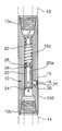
- FIG. 1 is schematic sectional view through a ball release tool
- FIG. 2 is a schematic sectional view through a ball release tool, where the tool has been actuated to release the ball.
- a ball release tool may be formed as a sub for installation into a string of tubulars.
- the tool and its method of use allows a ball to be released downhole to activate a tool, such as a liner hanger (item 8 in FIG. 2 ), fracing port, etc.
- a tool such as a liner hanger (item 8 in FIG. 2 ), fracing port, etc.
- the tool may be useful in situations where it is difficult to pump or release a ball at surface.
- a ball release sub may be placed in the tubular string above the tool to be actuated by the ball and below any tools that will inhibit passage therethrough of the ball, such as tools that are used to force the liner into the hole, which will not allow a ball to pass internally through the string.
- the ball release sub includes a pocket machined into the sub wall and an internal sleeve to hold the ball in place in the pocket.
- the ball would be placed in the pocket from the external of the sub and secured with a threaded plug.
- the sleeve may be connected to a check valve that allows flow down thru the running string and tools and, thereby, through the sleeve and sub, but does not allow flow up through the running string and tools.
- the check valve and the sleeve may be held down with a spring positioned to act against the sleeve or with shear pins.
- FIG. 1 shows one embodiment of a ball release sub.
- the ball release sub includes a tubular body 10 formed at its upper end 10 a and lower end 10 b for connection into a tubular string.
- ends 10 a , 10 b may be threaded or for threaded connection to adjacent tubulars above 12 and below 14 , as is usual in wellbore strings.
- Tubular body 10 includes an inner bore 10 c extending from end 10 a to end 10 b.
- a ball pocket 16 is formed in the inner wall of the tubular body.
- pocket 16 extends fully from an opening to inner bore 10 through to an opening to the exterior surface 10 d of the tubular member.
- pocket 16 includes a removable cap 18 that closes the pocket at its exterior surface, but may be removed to access the pocket from outside the sub, if desired.
- Cap 18 may be formed to seal against fluid leakage thought the tubular wall at pocket 16 such that fluid circulation is not allowed to bypass at that point.
- a sliding sleeve 20 is positioned for axial sliding movement within the inner bore.
- Sliding sleeve 20 includes a through bore 20 a that is substantially coaxially positioned with inner bore 10 c .
- the inner diameter of inner bore 10 c and through bore 20 a may be substantially the same as the selected minimum inner diameter of the remainder of the string.
- Sliding sleeve 20 is moveable from a first position ( FIG. 1 ) substantially covering pocket 16 and a second position ( FIG. 2 ) away from a blocking position over pocket 16 such that the pocket is opened to inner bore 10 c .
- Sliding sleeve 20 is normally maintained in the first position, as by being biased or pinned in that position.
- sleeve 20 is biased into a position covering the pocket by a spring 22 .
- Spring 22 drives the sleeve downwardly toward end 10 b against a stop 24 .
- spring 22 can be compressed to allow the sleeve to move away from the stop.
- Other means can be used to control the movement of the sleeve, as desired, such as shear pins.
- a check valve 26 is mounted in drive communication with sleeve 20 .
- Check valve 26 is configured to allow fluid flow, as shown by arrows F of FIG. 1 , in a direction from upper end 10 a to lower end 10 b , but resists or stops fluid flow in a reverse direction, as shown by arrows F R of FIG. 2 .
- check valve 26 allows normal fluid circulation from surface down through the string and up the annulus but acts against reverse circulation. This configuration allows the check valve 26 to act to drive the sleeve, when the well is reverse circulated.
- pocket to be selectively opened by controlling fluid flow in the well.
- check valve 26 creates a pressure differential above and below it, which acts to lift the sleeve toward the low pressure, upper side (toward upper end 10 a ).
- Spring 22 or shear pins are employed to control the movement of the sleeve such that only pressures similar to that created during reverse flow, rather than lesser, occasional backpressures, are capable of moving the sleeve.
- suitable seals may be provided, such as O-rings 28 to prevent leakage of fluid past the sleeve.
- the ball release sub is intended to release a ball when the sleeve is raised.
- a ball 30 may be positioned in pocket 16 .
- Sleeve 20 acts to block release of the ball from the pocket when in the first position.
- ball 30 can move out of pocket 16 , arrows B, past the sleeve when the sleeve is in the second position, raised out of a blocking position over the pocket.
- Ball 30 may be placed in the pocket at surface as by introducing the ball through the inner bore or, where there is a removable cap 18 , by removing the cap and inserting the ball. The ball can be installed prior to introducing the string into the well and the ball resides in the pocket, as by the blocking position of the sleeve, until it is desired to release the ball from the pocket.
- sleeve 20 maintains the ball in the pocket and fluid circulation is substantially not affected by the sleeve and check valve 26 .
- the fluid pressure lifts the sleeve, such that the ball can be released from the pocket, arrows B.
- normal fluid circulation can be resumed to convey the ball to its seat 32 .
- the ball is of a diameter selected to pass through the inner diameter of the string to its seat.
- the seat may be downstream from lower end 10 b and thus ball 30 is selected to at least pass through the inner bore diameter at lower end 10 b.
- a spring 34 may be positioned in pocket 16 , between a back wall of the pocket and the open area behind sleeve 20 , to act against a ball contained therein and force it out of the pocket, when sleeve 20 is removed from over the opening to inner bore 10 c.
Abstract
Description
Claims (9)
Priority Applications (1)
| Application Number | Priority Date | Filing Date | Title |
|---|---|---|---|
| US12/045,106 US7770652B2 (en) | 2007-03-13 | 2008-03-10 | Ball release procedure and release tool |
Applications Claiming Priority (2)
| Application Number | Priority Date | Filing Date | Title |
|---|---|---|---|
| US89456407P | 2007-03-13 | 2007-03-13 | |
| US12/045,106 US7770652B2 (en) | 2007-03-13 | 2008-03-10 | Ball release procedure and release tool |
Publications (2)
| Publication Number | Publication Date |
|---|---|
| US20080223586A1 US20080223586A1 (en) | 2008-09-18 |
| US7770652B2 true US7770652B2 (en) | 2010-08-10 |
Family
ID=39747262
Family Applications (1)
| Application Number | Title | Priority Date | Filing Date |
|---|---|---|---|
| US12/045,106 Expired - Fee Related US7770652B2 (en) | 2007-03-13 | 2008-03-10 | Ball release procedure and release tool |
Country Status (2)
| Country | Link |
|---|---|
| US (1) | US7770652B2 (en) |
| CA (1) | CA2625155C (en) |
Cited By (53)
| Publication number | Priority date | Publication date | Assignee | Title |
|---|---|---|---|---|
| US20110135530A1 (en) * | 2009-12-08 | 2011-06-09 | Zhiyue Xu | Method of making a nanomatrix powder metal compact |
| US8327931B2 (en) | 2009-12-08 | 2012-12-11 | Baker Hughes Incorporated | Multi-component disappearing tripping ball and method for making the same |
| US8424610B2 (en) | 2010-03-05 | 2013-04-23 | Baker Hughes Incorporated | Flow control arrangement and method |
| US8425651B2 (en) | 2010-07-30 | 2013-04-23 | Baker Hughes Incorporated | Nanomatrix metal composite |
| US8573295B2 (en) | 2010-11-16 | 2013-11-05 | Baker Hughes Incorporated | Plug and method of unplugging a seat |
| US8631876B2 (en) | 2011-04-28 | 2014-01-21 | Baker Hughes Incorporated | Method of making and using a functionally gradient composite tool |
| US8776884B2 (en) | 2010-08-09 | 2014-07-15 | Baker Hughes Incorporated | Formation treatment system and method |
| US8783365B2 (en) | 2011-07-28 | 2014-07-22 | Baker Hughes Incorporated | Selective hydraulic fracturing tool and method thereof |
| WO2014130288A1 (en) * | 2013-02-19 | 2014-08-28 | Halliburton Energy Services, Inc. | Systems and methods of positive indication of actuation of a downhole tool |
| US20150068727A1 (en) * | 2013-09-06 | 2015-03-12 | Baker Hughes Incorporated | Subterranean Tool for Release of Balls Adjacent Their Intended Destinations |
| US9022107B2 (en) | 2009-12-08 | 2015-05-05 | Baker Hughes Incorporated | Dissolvable tool |
| US9033055B2 (en) | 2011-08-17 | 2015-05-19 | Baker Hughes Incorporated | Selectively degradable passage restriction and method |
| US9057242B2 (en) | 2011-08-05 | 2015-06-16 | Baker Hughes Incorporated | Method of controlling corrosion rate in downhole article, and downhole article having controlled corrosion rate |
| US9068428B2 (en) | 2012-02-13 | 2015-06-30 | Baker Hughes Incorporated | Selectively corrodible downhole article and method of use |
| US9080098B2 (en) | 2011-04-28 | 2015-07-14 | Baker Hughes Incorporated | Functionally gradient composite article |
| US9090955B2 (en) | 2010-10-27 | 2015-07-28 | Baker Hughes Incorporated | Nanomatrix powder metal composite |
| US9090956B2 (en) | 2011-08-30 | 2015-07-28 | Baker Hughes Incorporated | Aluminum alloy powder metal compact |
| US9101978B2 (en) | 2002-12-08 | 2015-08-11 | Baker Hughes Incorporated | Nanomatrix powder metal compact |
| US9109269B2 (en) | 2011-08-30 | 2015-08-18 | Baker Hughes Incorporated | Magnesium alloy powder metal compact |
| US9109429B2 (en) | 2002-12-08 | 2015-08-18 | Baker Hughes Incorporated | Engineered powder compact composite material |
| US9127515B2 (en) | 2010-10-27 | 2015-09-08 | Baker Hughes Incorporated | Nanomatrix carbon composite |
| US9133695B2 (en) | 2011-09-03 | 2015-09-15 | Baker Hughes Incorporated | Degradable shaped charge and perforating gun system |
| US9139928B2 (en) | 2011-06-17 | 2015-09-22 | Baker Hughes Incorporated | Corrodible downhole article and method of removing the article from downhole environment |
| US9187990B2 (en) | 2011-09-03 | 2015-11-17 | Baker Hughes Incorporated | Method of using a degradable shaped charge and perforating gun system |
| US9227243B2 (en) | 2009-12-08 | 2016-01-05 | Baker Hughes Incorporated | Method of making a powder metal compact |
| US9243475B2 (en) | 2009-12-08 | 2016-01-26 | Baker Hughes Incorporated | Extruded powder metal compact |
| US9267347B2 (en) | 2009-12-08 | 2016-02-23 | Baker Huges Incorporated | Dissolvable tool |
| US9284812B2 (en) | 2011-11-21 | 2016-03-15 | Baker Hughes Incorporated | System for increasing swelling efficiency |
| US9347119B2 (en) | 2011-09-03 | 2016-05-24 | Baker Hughes Incorporated | Degradable high shock impedance material |
| US20160222764A1 (en) * | 2013-12-04 | 2016-08-04 | Halliburton Energy Services, Inc. | Ball drop tool and methods of use |
| US9605508B2 (en) | 2012-05-08 | 2017-03-28 | Baker Hughes Incorporated | Disintegrable and conformable metallic seal, and method of making the same |
| US9643144B2 (en) | 2011-09-02 | 2017-05-09 | Baker Hughes Incorporated | Method to generate and disperse nanostructures in a composite material |
| US9643250B2 (en) | 2011-07-29 | 2017-05-09 | Baker Hughes Incorporated | Method of controlling the corrosion rate of alloy particles, alloy particle with controlled corrosion rate, and articles comprising the particle |
| US9682425B2 (en) | 2009-12-08 | 2017-06-20 | Baker Hughes Incorporated | Coated metallic powder and method of making the same |
| US9708894B2 (en) | 2014-08-27 | 2017-07-18 | Baker Hughes Incorporated | Inertial occlusion release device |
| US9707739B2 (en) | 2011-07-22 | 2017-07-18 | Baker Hughes Incorporated | Intermetallic metallic composite, method of manufacture thereof and articles comprising the same |
| US9745847B2 (en) | 2014-08-27 | 2017-08-29 | Baker Hughes Incorporated | Conditional occlusion release device |
| US9816339B2 (en) | 2013-09-03 | 2017-11-14 | Baker Hughes, A Ge Company, Llc | Plug reception assembly and method of reducing restriction in a borehole |
| US9833838B2 (en) | 2011-07-29 | 2017-12-05 | Baker Hughes, A Ge Company, Llc | Method of controlling the corrosion rate of alloy particles, alloy particle with controlled corrosion rate, and articles comprising the particle |
| US9856547B2 (en) | 2011-08-30 | 2018-01-02 | Bakers Hughes, A Ge Company, Llc | Nanostructured powder metal compact |
| US9910026B2 (en) | 2015-01-21 | 2018-03-06 | Baker Hughes, A Ge Company, Llc | High temperature tracers for downhole detection of produced water |
| US9926766B2 (en) | 2012-01-25 | 2018-03-27 | Baker Hughes, A Ge Company, Llc | Seat for a tubular treating system |
| US9970264B2 (en) | 2014-06-03 | 2018-05-15 | Nov Downhole Eurasia Limited | Downhole actuation apparatus and associated methods |
| US10016810B2 (en) | 2015-12-14 | 2018-07-10 | Baker Hughes, A Ge Company, Llc | Methods of manufacturing degradable tools using a galvanic carrier and tools manufactured thereof |
| US10100601B2 (en) | 2014-12-16 | 2018-10-16 | Baker Hughes, A Ge Company, Llc | Downhole assembly having isolation tool and method |
| US10221637B2 (en) | 2015-08-11 | 2019-03-05 | Baker Hughes, A Ge Company, Llc | Methods of manufacturing dissolvable tools via liquid-solid state molding |
| US10240419B2 (en) | 2009-12-08 | 2019-03-26 | Baker Hughes, A Ge Company, Llc | Downhole flow inhibition tool and method of unplugging a seat |
| US10378303B2 (en) | 2015-03-05 | 2019-08-13 | Baker Hughes, A Ge Company, Llc | Downhole tool and method of forming the same |
| US10428623B2 (en) | 2016-11-01 | 2019-10-01 | Baker Hughes, A Ge Company, Llc | Ball dropping system and method |
| US10900323B2 (en) | 2017-11-06 | 2021-01-26 | Entech Solutions AS | Method and stimulation sleeve for well completion in a subterranean wellbore |
| US11167343B2 (en) | 2014-02-21 | 2021-11-09 | Terves, Llc | Galvanically-active in situ formed particles for controlled rate dissolving tools |
| US11365164B2 (en) | 2014-02-21 | 2022-06-21 | Terves, Llc | Fluid activated disintegrating metal system |
| US11649526B2 (en) | 2017-07-27 | 2023-05-16 | Terves, Llc | Degradable metal matrix composite |
Families Citing this family (8)
| Publication number | Priority date | Publication date | Assignee | Title |
|---|---|---|---|---|
| CA2625155C (en) * | 2007-03-13 | 2015-04-07 | Bbj Tools Inc. | Ball release procedure and release tool |
| US7571773B1 (en) * | 2008-04-17 | 2009-08-11 | Baker Hughes Incorporated | Multiple ball launch assemblies and methods of launching multiple balls into a wellbore |
| US9290998B2 (en) * | 2013-02-25 | 2016-03-22 | Baker Hughes Incorporated | Actuation mechanisms for downhole assemblies and related downhole assemblies and methods |
| CN106545310B (en) * | 2015-09-18 | 2019-02-15 | 中国石油化工股份有限公司 | A kind of underground automatic ball-throwing ball seat |
| WO2020009721A1 (en) * | 2018-07-05 | 2020-01-09 | Geodynamics, Inc. | Device and method for controlled release of a restriction element inside a well |
| GB2592670B (en) | 2020-03-06 | 2022-07-20 | M I Drilling Fluids Uk Ltd | Drill strings and related ball dropping tools |
| EP4139556A4 (en) * | 2020-04-24 | 2024-04-03 | Innovex Downhole Solutions Inc | Downhole tool with seal ring and slips assembly |
| CN113216897B (en) * | 2021-05-27 | 2022-07-08 | 大庆市天德忠石油科技有限公司 | Float collar float shoe for well cementation construction |
Citations (16)
| Publication number | Priority date | Publication date | Assignee | Title |
|---|---|---|---|---|
| US2737244A (en) * | 1952-04-25 | 1956-03-06 | Baker Oil Tools Inc | Multiple ball release devices for well tools |
| US3269463A (en) * | 1963-05-31 | 1966-08-30 | Jr John S Page | Well pressure responsive valve |
| US3332498A (en) * | 1964-11-12 | 1967-07-25 | Jr John S Page | Remote automatic control of subsurface valves |
| US3568768A (en) * | 1969-06-05 | 1971-03-09 | Cook Testing Co | Well pressure responsive valve |
| US3584645A (en) | 1969-12-30 | 1971-06-15 | Cook Testing Co | Flow control valve for wells |
| US3850194A (en) | 1973-01-09 | 1974-11-26 | Brown Oil Tools | Check valve assembly |
| US3850191A (en) * | 1973-01-09 | 1974-11-26 | Brown Oil Tools | Check valve assembly |
| US4040441A (en) * | 1973-01-09 | 1977-08-09 | Brown Cicero C | Check valve assembly |
| US4108203A (en) * | 1974-08-08 | 1978-08-22 | Brown Oil Tools, Inc. | Check valve assembly |
| US4171019A (en) | 1978-01-12 | 1979-10-16 | Davis-Lynch, Inc. | Apparatus and method for re-entering and cementing an underwater well |
| US4452322A (en) * | 1979-05-11 | 1984-06-05 | Christensen, Inc. | Drilling device for drilling a core in deep drill holes |
| US6220360B1 (en) | 2000-03-09 | 2001-04-24 | Halliburton Energy Services, Inc. | Downhole ball drop tool |
| US20040055753A1 (en) * | 2002-09-24 | 2004-03-25 | Davis John P. | Downhole ball dropping apparatus |
| US20050145417A1 (en) * | 2002-07-30 | 2005-07-07 | Radford Steven R. | Expandable reamer apparatus for enlarging subterranean boreholes and methods of use |
| US20080223586A1 (en) * | 2007-03-13 | 2008-09-18 | Bbj Tools Inc. | Ball release procedure and release tool |
| US7624810B2 (en) * | 2007-12-21 | 2009-12-01 | Schlumberger Technology Corporation | Ball dropping assembly and technique for use in a well |
-
2008
- 2008-03-10 CA CA 2625155 patent/CA2625155C/en not_active Expired - Fee Related
- 2008-03-10 US US12/045,106 patent/US7770652B2/en not_active Expired - Fee Related
Patent Citations (18)
| Publication number | Priority date | Publication date | Assignee | Title |
|---|---|---|---|---|
| US2737244A (en) * | 1952-04-25 | 1956-03-06 | Baker Oil Tools Inc | Multiple ball release devices for well tools |
| US3269463A (en) * | 1963-05-31 | 1966-08-30 | Jr John S Page | Well pressure responsive valve |
| US3332498A (en) * | 1964-11-12 | 1967-07-25 | Jr John S Page | Remote automatic control of subsurface valves |
| US3568768A (en) * | 1969-06-05 | 1971-03-09 | Cook Testing Co | Well pressure responsive valve |
| US3584645A (en) | 1969-12-30 | 1971-06-15 | Cook Testing Co | Flow control valve for wells |
| US3850194A (en) | 1973-01-09 | 1974-11-26 | Brown Oil Tools | Check valve assembly |
| US3850191A (en) * | 1973-01-09 | 1974-11-26 | Brown Oil Tools | Check valve assembly |
| US4040441A (en) * | 1973-01-09 | 1977-08-09 | Brown Cicero C | Check valve assembly |
| US4108203A (en) * | 1974-08-08 | 1978-08-22 | Brown Oil Tools, Inc. | Check valve assembly |
| US4171019A (en) | 1978-01-12 | 1979-10-16 | Davis-Lynch, Inc. | Apparatus and method for re-entering and cementing an underwater well |
| US4452322A (en) * | 1979-05-11 | 1984-06-05 | Christensen, Inc. | Drilling device for drilling a core in deep drill holes |
| US6220360B1 (en) | 2000-03-09 | 2001-04-24 | Halliburton Energy Services, Inc. | Downhole ball drop tool |
| US20050145417A1 (en) * | 2002-07-30 | 2005-07-07 | Radford Steven R. | Expandable reamer apparatus for enlarging subterranean boreholes and methods of use |
| US20080105465A1 (en) * | 2002-07-30 | 2008-05-08 | Baker Hughes Incorporated | Expandable reamer for subterranean boreholes and methods of use |
| US20040055753A1 (en) * | 2002-09-24 | 2004-03-25 | Davis John P. | Downhole ball dropping apparatus |
| US7100700B2 (en) | 2002-09-24 | 2006-09-05 | Baker Hughes Incorporated | Downhole ball dropping apparatus |
| US20080223586A1 (en) * | 2007-03-13 | 2008-09-18 | Bbj Tools Inc. | Ball release procedure and release tool |
| US7624810B2 (en) * | 2007-12-21 | 2009-12-01 | Schlumberger Technology Corporation | Ball dropping assembly and technique for use in a well |
Cited By (71)
| Publication number | Priority date | Publication date | Assignee | Title |
|---|---|---|---|---|
| US9101978B2 (en) | 2002-12-08 | 2015-08-11 | Baker Hughes Incorporated | Nanomatrix powder metal compact |
| US9109429B2 (en) | 2002-12-08 | 2015-08-18 | Baker Hughes Incorporated | Engineered powder compact composite material |
| US10240419B2 (en) | 2009-12-08 | 2019-03-26 | Baker Hughes, A Ge Company, Llc | Downhole flow inhibition tool and method of unplugging a seat |
| US8327931B2 (en) | 2009-12-08 | 2012-12-11 | Baker Hughes Incorporated | Multi-component disappearing tripping ball and method for making the same |
| US9267347B2 (en) | 2009-12-08 | 2016-02-23 | Baker Huges Incorporated | Dissolvable tool |
| US9243475B2 (en) | 2009-12-08 | 2016-01-26 | Baker Hughes Incorporated | Extruded powder metal compact |
| US8714268B2 (en) | 2009-12-08 | 2014-05-06 | Baker Hughes Incorporated | Method of making and using multi-component disappearing tripping ball |
| US9227243B2 (en) | 2009-12-08 | 2016-01-05 | Baker Hughes Incorporated | Method of making a powder metal compact |
| US10669797B2 (en) | 2009-12-08 | 2020-06-02 | Baker Hughes, A Ge Company, Llc | Tool configured to dissolve in a selected subsurface environment |
| US20110135530A1 (en) * | 2009-12-08 | 2011-06-09 | Zhiyue Xu | Method of making a nanomatrix powder metal compact |
| US9682425B2 (en) | 2009-12-08 | 2017-06-20 | Baker Hughes Incorporated | Coated metallic powder and method of making the same |
| US9022107B2 (en) | 2009-12-08 | 2015-05-05 | Baker Hughes Incorporated | Dissolvable tool |
| US9079246B2 (en) | 2009-12-08 | 2015-07-14 | Baker Hughes Incorporated | Method of making a nanomatrix powder metal compact |
| US8424610B2 (en) | 2010-03-05 | 2013-04-23 | Baker Hughes Incorporated | Flow control arrangement and method |
| US8425651B2 (en) | 2010-07-30 | 2013-04-23 | Baker Hughes Incorporated | Nanomatrix metal composite |
| US8776884B2 (en) | 2010-08-09 | 2014-07-15 | Baker Hughes Incorporated | Formation treatment system and method |
| US9127515B2 (en) | 2010-10-27 | 2015-09-08 | Baker Hughes Incorporated | Nanomatrix carbon composite |
| US9090955B2 (en) | 2010-10-27 | 2015-07-28 | Baker Hughes Incorporated | Nanomatrix powder metal composite |
| US8573295B2 (en) | 2010-11-16 | 2013-11-05 | Baker Hughes Incorporated | Plug and method of unplugging a seat |
| US9080098B2 (en) | 2011-04-28 | 2015-07-14 | Baker Hughes Incorporated | Functionally gradient composite article |
| US9631138B2 (en) | 2011-04-28 | 2017-04-25 | Baker Hughes Incorporated | Functionally gradient composite article |
| US10335858B2 (en) | 2011-04-28 | 2019-07-02 | Baker Hughes, A Ge Company, Llc | Method of making and using a functionally gradient composite tool |
| US8631876B2 (en) | 2011-04-28 | 2014-01-21 | Baker Hughes Incorporated | Method of making and using a functionally gradient composite tool |
| US9926763B2 (en) | 2011-06-17 | 2018-03-27 | Baker Hughes, A Ge Company, Llc | Corrodible downhole article and method of removing the article from downhole environment |
| US9139928B2 (en) | 2011-06-17 | 2015-09-22 | Baker Hughes Incorporated | Corrodible downhole article and method of removing the article from downhole environment |
| US9707739B2 (en) | 2011-07-22 | 2017-07-18 | Baker Hughes Incorporated | Intermetallic metallic composite, method of manufacture thereof and articles comprising the same |
| US10697266B2 (en) | 2011-07-22 | 2020-06-30 | Baker Hughes, A Ge Company, Llc | Intermetallic metallic composite, method of manufacture thereof and articles comprising the same |
| US8783365B2 (en) | 2011-07-28 | 2014-07-22 | Baker Hughes Incorporated | Selective hydraulic fracturing tool and method thereof |
| US9643250B2 (en) | 2011-07-29 | 2017-05-09 | Baker Hughes Incorporated | Method of controlling the corrosion rate of alloy particles, alloy particle with controlled corrosion rate, and articles comprising the particle |
| US9833838B2 (en) | 2011-07-29 | 2017-12-05 | Baker Hughes, A Ge Company, Llc | Method of controlling the corrosion rate of alloy particles, alloy particle with controlled corrosion rate, and articles comprising the particle |
| US10092953B2 (en) | 2011-07-29 | 2018-10-09 | Baker Hughes, A Ge Company, Llc | Method of controlling the corrosion rate of alloy particles, alloy particle with controlled corrosion rate, and articles comprising the particle |
| US9057242B2 (en) | 2011-08-05 | 2015-06-16 | Baker Hughes Incorporated | Method of controlling corrosion rate in downhole article, and downhole article having controlled corrosion rate |
| US9033055B2 (en) | 2011-08-17 | 2015-05-19 | Baker Hughes Incorporated | Selectively degradable passage restriction and method |
| US10301909B2 (en) | 2011-08-17 | 2019-05-28 | Baker Hughes, A Ge Company, Llc | Selectively degradable passage restriction |
| US9925589B2 (en) | 2011-08-30 | 2018-03-27 | Baker Hughes, A Ge Company, Llc | Aluminum alloy powder metal compact |
| US9802250B2 (en) | 2011-08-30 | 2017-10-31 | Baker Hughes | Magnesium alloy powder metal compact |
| US9109269B2 (en) | 2011-08-30 | 2015-08-18 | Baker Hughes Incorporated | Magnesium alloy powder metal compact |
| US9090956B2 (en) | 2011-08-30 | 2015-07-28 | Baker Hughes Incorporated | Aluminum alloy powder metal compact |
| US9856547B2 (en) | 2011-08-30 | 2018-01-02 | Bakers Hughes, A Ge Company, Llc | Nanostructured powder metal compact |
| US10737321B2 (en) | 2011-08-30 | 2020-08-11 | Baker Hughes, A Ge Company, Llc | Magnesium alloy powder metal compact |
| US11090719B2 (en) | 2011-08-30 | 2021-08-17 | Baker Hughes, A Ge Company, Llc | Aluminum alloy powder metal compact |
| US9643144B2 (en) | 2011-09-02 | 2017-05-09 | Baker Hughes Incorporated | Method to generate and disperse nanostructures in a composite material |
| US9133695B2 (en) | 2011-09-03 | 2015-09-15 | Baker Hughes Incorporated | Degradable shaped charge and perforating gun system |
| US9187990B2 (en) | 2011-09-03 | 2015-11-17 | Baker Hughes Incorporated | Method of using a degradable shaped charge and perforating gun system |
| US9347119B2 (en) | 2011-09-03 | 2016-05-24 | Baker Hughes Incorporated | Degradable high shock impedance material |
| US9284812B2 (en) | 2011-11-21 | 2016-03-15 | Baker Hughes Incorporated | System for increasing swelling efficiency |
| US9926766B2 (en) | 2012-01-25 | 2018-03-27 | Baker Hughes, A Ge Company, Llc | Seat for a tubular treating system |
| US9068428B2 (en) | 2012-02-13 | 2015-06-30 | Baker Hughes Incorporated | Selectively corrodible downhole article and method of use |
| US9605508B2 (en) | 2012-05-08 | 2017-03-28 | Baker Hughes Incorporated | Disintegrable and conformable metallic seal, and method of making the same |
| US10612659B2 (en) | 2012-05-08 | 2020-04-07 | Baker Hughes Oilfield Operations, Llc | Disintegrable and conformable metallic seal, and method of making the same |
| WO2014130288A1 (en) * | 2013-02-19 | 2014-08-28 | Halliburton Energy Services, Inc. | Systems and methods of positive indication of actuation of a downhole tool |
| US9068439B2 (en) | 2013-02-19 | 2015-06-30 | Halliburton Energy Services, Inc. | Systems and methods of positive indication of actuation of a downhole tool |
| US9816339B2 (en) | 2013-09-03 | 2017-11-14 | Baker Hughes, A Ge Company, Llc | Plug reception assembly and method of reducing restriction in a borehole |
| US20150068727A1 (en) * | 2013-09-06 | 2015-03-12 | Baker Hughes Incorporated | Subterranean Tool for Release of Balls Adjacent Their Intended Destinations |
| US9719321B2 (en) * | 2013-09-06 | 2017-08-01 | Baker Hughes Incorporated | Subterranean tool for release of balls adjacent their intended destinations |
| US20160222764A1 (en) * | 2013-12-04 | 2016-08-04 | Halliburton Energy Services, Inc. | Ball drop tool and methods of use |
| US11613952B2 (en) | 2014-02-21 | 2023-03-28 | Terves, Llc | Fluid activated disintegrating metal system |
| US11365164B2 (en) | 2014-02-21 | 2022-06-21 | Terves, Llc | Fluid activated disintegrating metal system |
| US11167343B2 (en) | 2014-02-21 | 2021-11-09 | Terves, Llc | Galvanically-active in situ formed particles for controlled rate dissolving tools |
| US9970264B2 (en) | 2014-06-03 | 2018-05-15 | Nov Downhole Eurasia Limited | Downhole actuation apparatus and associated methods |
| US9708894B2 (en) | 2014-08-27 | 2017-07-18 | Baker Hughes Incorporated | Inertial occlusion release device |
| US9745847B2 (en) | 2014-08-27 | 2017-08-29 | Baker Hughes Incorporated | Conditional occlusion release device |
| US10100601B2 (en) | 2014-12-16 | 2018-10-16 | Baker Hughes, A Ge Company, Llc | Downhole assembly having isolation tool and method |
| US9910026B2 (en) | 2015-01-21 | 2018-03-06 | Baker Hughes, A Ge Company, Llc | High temperature tracers for downhole detection of produced water |
| US10378303B2 (en) | 2015-03-05 | 2019-08-13 | Baker Hughes, A Ge Company, Llc | Downhole tool and method of forming the same |
| US10221637B2 (en) | 2015-08-11 | 2019-03-05 | Baker Hughes, A Ge Company, Llc | Methods of manufacturing dissolvable tools via liquid-solid state molding |
| US10016810B2 (en) | 2015-12-14 | 2018-07-10 | Baker Hughes, A Ge Company, Llc | Methods of manufacturing degradable tools using a galvanic carrier and tools manufactured thereof |
| US10428623B2 (en) | 2016-11-01 | 2019-10-01 | Baker Hughes, A Ge Company, Llc | Ball dropping system and method |
| US11649526B2 (en) | 2017-07-27 | 2023-05-16 | Terves, Llc | Degradable metal matrix composite |
| US11898223B2 (en) | 2017-07-27 | 2024-02-13 | Terves, Llc | Degradable metal matrix composite |
| US10900323B2 (en) | 2017-11-06 | 2021-01-26 | Entech Solutions AS | Method and stimulation sleeve for well completion in a subterranean wellbore |
Also Published As
| Publication number | Publication date |
|---|---|
| CA2625155C (en) | 2015-04-07 |
| US20080223586A1 (en) | 2008-09-18 |
| CA2625155A1 (en) | 2008-09-13 |
Similar Documents
| Publication | Publication Date | Title |
|---|---|---|
| US7770652B2 (en) | Ball release procedure and release tool | |
| US7878237B2 (en) | Actuation system for an oilfield tubular handling system | |
| US6684950B2 (en) | System for pressure testing tubing | |
| US7913769B2 (en) | Downhole safety valve apparatus and method | |
| CA2440922C (en) | Downhole tool | |
| CA2560333C (en) | Spear type blow out preventer | |
| AU2018256467B2 (en) | Downhole tool method and device | |
| AU2010308242B2 (en) | Pressure equalizing a ball valve through an upper seal bypass | |
| AU783421B2 (en) | Float valve assembly for downhole tubulars | |
| WO2008076189A3 (en) | Downhole tool with slip releasing mechanism | |
| CA2616137A1 (en) | A shoe for wellbore lining tubing | |
| US8082941B2 (en) | Reverse action flow activated shut-off valve | |
| US7677304B1 (en) | Passable no-go device for downhole valve | |
| US7779919B2 (en) | Flapper valve retention method and system | |
| GB2411683A (en) | Tubing and valve system for pressure testing in a well | |
| CA2560828C (en) | Actuation system for an oilfield tubular handling system | |
| EP1144803A2 (en) | Downhole flapper valve assembly |
Legal Events
| Date | Code | Title | Description |
|---|---|---|---|
| AS | Assignment |
Owner name: BBJ TOOLS INC., CANADA Free format text: ASSIGNMENT OF ASSIGNORS INTEREST;ASSIGNOR:BARNETT, ROBERT;REEL/FRAME:020998/0213 Effective date: 20080409 |
|
| STCF | Information on status: patent grant |
Free format text: PATENTED CASE |
|
| FPAY | Fee payment |
Year of fee payment: 4 |
|
| MAFP | Maintenance fee payment |
Free format text: PAYMENT OF MAINTENANCE FEE, 8TH YR, SMALL ENTITY (ORIGINAL EVENT CODE: M2552) Year of fee payment: 8 |
|
| FEPP | Fee payment procedure |
Free format text: MAINTENANCE FEE REMINDER MAILED (ORIGINAL EVENT CODE: REM.); ENTITY STATUS OF PATENT OWNER: SMALL ENTITY |
|
| LAPS | Lapse for failure to pay maintenance fees |
Free format text: PATENT EXPIRED FOR FAILURE TO PAY MAINTENANCE FEES (ORIGINAL EVENT CODE: EXP.); ENTITY STATUS OF PATENT OWNER: SMALL ENTITY |
|
| STCH | Information on status: patent discontinuation |
Free format text: PATENT EXPIRED DUE TO NONPAYMENT OF MAINTENANCE FEES UNDER 37 CFR 1.362 |
|
| FP | Lapsed due to failure to pay maintenance fee |
Effective date: 20220810 |