US7766505B2 - Light source assembly - Google Patents
Light source assembly Download PDFInfo
- Publication number
- US7766505B2 US7766505B2 US12/202,577 US20257708A US7766505B2 US 7766505 B2 US7766505 B2 US 7766505B2 US 20257708 A US20257708 A US 20257708A US 7766505 B2 US7766505 B2 US 7766505B2
- Authority
- US
- United States
- Prior art keywords
- light source
- connecting part
- heat
- groove
- dissipating base
- Prior art date
- Legal status (The legal status is an assumption and is not a legal conclusion. Google has not performed a legal analysis and makes no representation as to the accuracy of the status listed.)
- Expired - Fee Related
Links
Images


Classifications
-
- F—MECHANICAL ENGINEERING; LIGHTING; HEATING; WEAPONS; BLASTING
- F21—LIGHTING
- F21S—NON-PORTABLE LIGHTING DEVICES; SYSTEMS THEREOF; VEHICLE LIGHTING DEVICES SPECIALLY ADAPTED FOR VEHICLE EXTERIORS
- F21S4/00—Lighting devices or systems using a string or strip of light sources
- F21S4/20—Lighting devices or systems using a string or strip of light sources with light sources held by or within elongate supports
- F21S4/28—Lighting devices or systems using a string or strip of light sources with light sources held by or within elongate supports rigid, e.g. LED bars
-
- F—MECHANICAL ENGINEERING; LIGHTING; HEATING; WEAPONS; BLASTING
- F21—LIGHTING
- F21S—NON-PORTABLE LIGHTING DEVICES; SYSTEMS THEREOF; VEHICLE LIGHTING DEVICES SPECIALLY ADAPTED FOR VEHICLE EXTERIORS
- F21S2/00—Systems of lighting devices, not provided for in main groups F21S4/00 - F21S10/00 or F21S19/00, e.g. of modular construction
- F21S2/005—Systems of lighting devices, not provided for in main groups F21S4/00 - F21S10/00 or F21S19/00, e.g. of modular construction of modular construction
-
- F—MECHANICAL ENGINEERING; LIGHTING; HEATING; WEAPONS; BLASTING
- F21—LIGHTING
- F21V—FUNCTIONAL FEATURES OR DETAILS OF LIGHTING DEVICES OR SYSTEMS THEREOF; STRUCTURAL COMBINATIONS OF LIGHTING DEVICES WITH OTHER ARTICLES, NOT OTHERWISE PROVIDED FOR
- F21V15/00—Protecting lighting devices from damage
- F21V15/01—Housings, e.g. material or assembling of housing parts
- F21V15/013—Housings, e.g. material or assembling of housing parts the housing being an extrusion
-
- F—MECHANICAL ENGINEERING; LIGHTING; HEATING; WEAPONS; BLASTING
- F21—LIGHTING
- F21V—FUNCTIONAL FEATURES OR DETAILS OF LIGHTING DEVICES OR SYSTEMS THEREOF; STRUCTURAL COMBINATIONS OF LIGHTING DEVICES WITH OTHER ARTICLES, NOT OTHERWISE PROVIDED FOR
- F21V21/00—Supporting, suspending, or attaching arrangements for lighting devices; Hand grips
- F21V21/005—Supporting, suspending, or attaching arrangements for lighting devices; Hand grips for several lighting devices in an end-to-end arrangement, i.e. light tracks
-
- F—MECHANICAL ENGINEERING; LIGHTING; HEATING; WEAPONS; BLASTING
- F21—LIGHTING
- F21V—FUNCTIONAL FEATURES OR DETAILS OF LIGHTING DEVICES OR SYSTEMS THEREOF; STRUCTURAL COMBINATIONS OF LIGHTING DEVICES WITH OTHER ARTICLES, NOT OTHERWISE PROVIDED FOR
- F21V21/00—Supporting, suspending, or attaching arrangements for lighting devices; Hand grips
- F21V21/14—Adjustable mountings
- F21V21/30—Pivoted housings or frames
-
- F—MECHANICAL ENGINEERING; LIGHTING; HEATING; WEAPONS; BLASTING
- F21—LIGHTING
- F21V—FUNCTIONAL FEATURES OR DETAILS OF LIGHTING DEVICES OR SYSTEMS THEREOF; STRUCTURAL COMBINATIONS OF LIGHTING DEVICES WITH OTHER ARTICLES, NOT OTHERWISE PROVIDED FOR
- F21V29/00—Protecting lighting devices from thermal damage; Cooling or heating arrangements specially adapted for lighting devices or systems
- F21V29/50—Cooling arrangements
- F21V29/70—Cooling arrangements characterised by passive heat-dissipating elements, e.g. heat-sinks
- F21V29/74—Cooling arrangements characterised by passive heat-dissipating elements, e.g. heat-sinks with fins or blades
- F21V29/76—Cooling arrangements characterised by passive heat-dissipating elements, e.g. heat-sinks with fins or blades with essentially identical parallel planar fins or blades, e.g. with comb-like cross-section
- F21V29/763—Cooling arrangements characterised by passive heat-dissipating elements, e.g. heat-sinks with fins or blades with essentially identical parallel planar fins or blades, e.g. with comb-like cross-section the planes containing the fins or blades having the direction of the light emitting axis
-
- F—MECHANICAL ENGINEERING; LIGHTING; HEATING; WEAPONS; BLASTING
- F21—LIGHTING
- F21W—INDEXING SCHEME ASSOCIATED WITH SUBCLASSES F21K, F21L, F21S and F21V, RELATING TO USES OR APPLICATIONS OF LIGHTING DEVICES OR SYSTEMS
- F21W2131/00—Use or application of lighting devices or systems not provided for in codes F21W2102/00-F21W2121/00
- F21W2131/10—Outdoor lighting
- F21W2131/105—Outdoor lighting of arenas or the like
-
- F—MECHANICAL ENGINEERING; LIGHTING; HEATING; WEAPONS; BLASTING
- F21—LIGHTING
- F21Y—INDEXING SCHEME ASSOCIATED WITH SUBCLASSES F21K, F21L, F21S and F21V, RELATING TO THE FORM OR THE KIND OF THE LIGHT SOURCES OR OF THE COLOUR OF THE LIGHT EMITTED
- F21Y2103/00—Elongate light sources, e.g. fluorescent tubes
- F21Y2103/10—Elongate light sources, e.g. fluorescent tubes comprising a linear array of point-like light-generating elements
-
- F—MECHANICAL ENGINEERING; LIGHTING; HEATING; WEAPONS; BLASTING
- F21—LIGHTING
- F21Y—INDEXING SCHEME ASSOCIATED WITH SUBCLASSES F21K, F21L, F21S and F21V, RELATING TO THE FORM OR THE KIND OF THE LIGHT SOURCES OR OF THE COLOUR OF THE LIGHT EMITTED
- F21Y2115/00—Light-generating elements of semiconductor light sources
- F21Y2115/10—Light-emitting diodes [LED]
Definitions
- the present invention relates to a light source assembly, and particularly, to a light source assembly capable of large-area illumination.
- Light source modules such as incandescence lamps, fluorescent lamps and halogen lamps, generally have a limited illumination area. However, it is not adequate to use these light source modules in certain areas, such as stadiums and stages, where a large-area illumination is needed.
- a plurality of light source modules can be used simultaneously, each of which works independently.
- the light source modules are arranged independently, it can be difficult and troublesome to install.
- An exemplary light source assembly includes a first light source module and a second light source module.
- the first light source module includes a first light source, a first heat-dissipating base, and a first connecting part.
- the first heat-dissipating base has a first side and an opposite second side.
- the first light source is mounted on the first side of the first heat-dissipating base, and the first connecting part extends outwardly from the second side of the first heat-dissipating base.
- the second light source module includes a second light source, a second heat-dissipating base, and a second connecting part.
- the second heat-dissipating base has a first side and an opposite second side.
- the second light source is mounted on the first side of the second heat-dissipating base, and the second connecting part extends outwardly from the second side of the second heat-dissipating base.
- the first connecting part is detachably and slidably engaged with the second connecting part.
- FIG. 1 is an exploded perspective view of a light source assembly according to a first embodiment.
- FIG. 2 is a perspective view of the assembled light source assembly of FIG. 1 .
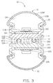
- FIG. 3 is a side, cross-sectional view of the assembled light source assembly of FIG. 2 taken along the line III-III thereof.
- FIG. 4 is a side, cross-sectional view of an assembled light source assembly according to a second embodiment.
- FIG. 5 is a side, cross-sectional view of an assembled light source assembly according to a third embodiment.
- a light source assembly 10 includes a first light source module 11 and a second light source module 12 .
- the first light source module 11 faces away from the second light source module 12 .
- the first light source module 11 is elongated.
- the first light source module 11 includes a heat-dissipating base 111 , a circuit board 112 , a light source 113 disposed in the heat-dissipating base 111 , a light pervious cover 115 , a first connecting part 131 and a second connecting part 132 .
- the light source 113 can include at least one light emitting diode (LED).
- the light source 113 can be attached to the circuit board 112 via a thermally conductive adhesive 1130 , for example, a silver colloid.
- the circuit board 112 is mounted on the heat-dissipating base 111 so that the light source 113 is thermally connected with the heat-dissipating base 111 .
- the heat generated from the light source 113 is conveyed to the heat-dissipating base 111 , subsequently dissipating in air.
- the light source 113 can be mounted on the circuit board 112 via eutectic sintering or soldering with solder balls.
- the heat-dissipating base 111 includes a plurality of heat-dissipating fins 1110 extending outwardly in a direction away from the light source 113 .
- the heat-dissipating fins 1110 increase a contact area between the heat-dissipating base 111 and the air to dissipate the heat generated by the light source 113 more efficiently.
- the heat-dissipating base 111 can be made of metal with a high thermal conductivity, for example, aluminum, copper, or stainless steel.
- the first connecting part 131 and the second connecting part 132 extend outwardly from the heat-dissipating base 111 .
- the first connecting part 131 has a substantially circular cross-section, while the second connecting part 132 is a substantially elongated C-shaped protrusion.
- the first connecting part 131 has an outline of an arc in cross-section, while the second connecting part 132 is substantially C-shaped in cross-section.
- the second connecting part 132 defines a substantially elongated cylindrical groove therein.
- the first connecting part 131 and the second connecting part 132 both have an outline of a major arc in their respective cross-sections.
- the light pervious cover 115 and the heat-dissipating base 111 cooperatively define an accommodating space 110 therein for receiving the light source 113 .
- the light pervious cover 115 includes a light incident surface 1150 and an opposite light emitting surface 1152 .
- the light emitted from the light source 113 reaches the light incident surface 1150 , passes through the light pervious cover 115 , and then emits out from the light emitting surface 1152 .
- the light emitting surface 1152 can be a smooth or rough surface. In the present embodiment, the light emitting surface 1152 is a rough surface. After the light emitted from the light source 113 transmits through the light pervious cover 115 , the light emits uniformly from the light emitting surface 1152 .
- the light cover 115 can have a plurality of light converging lenses or light diverging lenses formed on the light emitting surface 1152 for converging or diverging the light emitted from the light source 113 , depending on the application and usage requirements.
- the light pervious cover 115 can be made of transparent material. Particularly, the light pervious cover 115 can be made of hard transparent material so that the light pervious cover 115 protects the light source 113 from damage.
- the hard transparent material can be polymethyl methacrylate (PMMA), poly carbonate (PC), silicone, epoxy, or polyacrylate.
- the second light source module 12 faces away from the first light source module 11 .
- the second light source module 12 includes a heat-dissipating base 121 , a light source 123 attached to the heat-dissipating base 121 , a light pervious cover 125 , a third connecting part 133 , and a fourth connecting part 134 .
- Both the third connecting part 133 and the fourth connecting part 134 extend outwardly from the heat-dissipating base 121 .
- the third connecting part 134 is a substantially elongated C-shaped protrusion; similar to the first connecting part 131 , the fourth connecting part 134 has a substantially circular cross-section.
- the second connecting part 132 defines a substantially elongated cylindrical groove therein.
- first connecting part 131 is aligned with one end of the third connecting part 133
- second connecting part 132 is aligned with one end of the fourth connecting part.
- the first light source module 10 slides along the lengthwise direction of the second light source module 12 relative to the second light source module 12 until the first connecting part 131 is entirely received in the groove of the second light source module 12 and the fourth light source module 134 is entirely received in the groove of the second light source module 132 .
- first light source module 11 and the second light source module 12 are back-to-back.
- the first light source module 11 and the second light source module 12 are slidably and detachably engaged with each other.
- a light source assembly 10 according to a second embodiment is shown.
- the light source assembly 10 of the present embodiment is similar to that of the first embodiment, with the exception that the first light source module 11 includes only one first connecting part 131 and the second light source module 12 includes only one second connecting part 132 .
- the first light source module 11 is capable of rotating a predetermined angle (e.g., from 0 degrees to 15 degrees) around a central axis of the first connecting part 131 relative to the second light source module 12 .
- the light source assembly 30 includes a first light source module 31 , a second light source module 32 , and a connecting shaft 333 connected between the first light source module 31 and the second light source module 32 .
- the connecting shaft 333 is slidably and detachably coupled to the first light source module 31 and the second light source module 32 .
- the first light source module 31 includes a first connecting part 331
- the second light source module 32 includes a second connecting part 332 .
- the first connecting part 331 is similar to the second connecting part 132 of FIG. 3 according to the first embodiment.
- the first connecting part 331 defines a substantially elongated cylindrical groove therein.
- the second light source module 32 has the same shape as the first light source module 31 .
- the second connecting part 332 defines a substantially elongated cylindrical groove therein.
- the connecting shaft 333 includes two interconnected parallel cylinders that are integrally formed.
- the connecting shaft 333 has an outline of an Arabic numeral “8”. After the light source assembly 30 has been assembled, each cylinder of the connecting shaft 333 is partly received in a corresponding cylindrical groove of the first connecting part 331 and the second connecting part 332 .
- the first light source module 31 is capable of rotating a predetermined angle (e.g., from 0 degrees to 15 degrees) around a central axis of the connecting shaft 333 relative to the second light source module 12 .
Abstract
A light source assembly includes a first and a second light source modules. The first light source module includes a first light source, a first heat-dissipating base, and a first connecting part. The first heat-dissipating base has a first side and a second side. The first light source is mounted on the first side of the first heat-dissipating base, and the first connecting part extends outwardly from the second side of the first heat-dissipating base. The second light source module includes a second light source, a second heat-dissipating base, and a second connecting part. The second heat-dissipating base has a first side and a second side. The second light source is mounted on the first side of the second heat-dissipating base, and the second connecting part extends outwardly from the second side. The first connecting part is detachably and slidably engaged with the second connecting part.
Description
This application is related to the commonly-assigned copending application: Ser. No. 12/177,424, entitled “ILLUMINATION DEVICE”. The Disclosure of the above-identified application is incorporated herein by reference.
1. Technical Field
The present invention relates to a light source assembly, and particularly, to a light source assembly capable of large-area illumination.
2. Description of Related Art
Light source modules, such as incandescence lamps, fluorescent lamps and halogen lamps, generally have a limited illumination area. However, it is not adequate to use these light source modules in certain areas, such as stadiums and stages, where a large-area illumination is needed.
In order to illuminate a large area, a plurality of light source modules can be used simultaneously, each of which works independently. However, since the light source modules are arranged independently, it can be difficult and troublesome to install.
Therefore, a new light source assembly is desired to overcome the above mentioned problems.
An exemplary light source assembly includes a first light source module and a second light source module. The first light source module includes a first light source, a first heat-dissipating base, and a first connecting part. The first heat-dissipating base has a first side and an opposite second side. The first light source is mounted on the first side of the first heat-dissipating base, and the first connecting part extends outwardly from the second side of the first heat-dissipating base. The second light source module includes a second light source, a second heat-dissipating base, and a second connecting part. The second heat-dissipating base has a first side and an opposite second side. The second light source is mounted on the first side of the second heat-dissipating base, and the second connecting part extends outwardly from the second side of the second heat-dissipating base. The first connecting part is detachably and slidably engaged with the second connecting part.
Many aspects of the embodiments can be better understood with references to the following drawings. The components in the drawings are not necessarily drawn to scale, the emphasis instead being placed upon clearly illustrating the principles of the present embodiments. Moreover, in the drawings, like reference numerals designate corresponding parts throughout the several views.
Embodiments will now be described in detail below with references to the drawings.
Referring to FIGS. 1-2 , a light source assembly 10 includes a first light source module 11 and a second light source module 12. The first light source module 11 faces away from the second light source module 12.
Referring to FIGS. 1-3 , the first light source module 11 is elongated. The first light source module 11 includes a heat-dissipating base 111, a circuit board 112, a light source 113 disposed in the heat-dissipating base 111, a light pervious cover 115, a first connecting part 131 and a second connecting part 132. The light source 113 can include at least one light emitting diode (LED). The light source 113 can be attached to the circuit board 112 via a thermally conductive adhesive 1130, for example, a silver colloid. The circuit board 112 is mounted on the heat-dissipating base 111 so that the light source 113 is thermally connected with the heat-dissipating base 111. The heat generated from the light source 113 is conveyed to the heat-dissipating base 111, subsequently dissipating in air. The light source 113 can be mounted on the circuit board 112 via eutectic sintering or soldering with solder balls.
The heat-dissipating base 111 includes a plurality of heat-dissipating fins 1110 extending outwardly in a direction away from the light source 113. The heat-dissipating fins 1110 increase a contact area between the heat-dissipating base 111 and the air to dissipate the heat generated by the light source 113 more efficiently. The heat-dissipating base 111 can be made of metal with a high thermal conductivity, for example, aluminum, copper, or stainless steel.
The first connecting part 131 and the second connecting part 132 extend outwardly from the heat-dissipating base 111. The first connecting part 131 has a substantially circular cross-section, while the second connecting part 132 is a substantially elongated C-shaped protrusion. The first connecting part 131 has an outline of an arc in cross-section, while the second connecting part 132 is substantially C-shaped in cross-section. The second connecting part 132 defines a substantially elongated cylindrical groove therein. The first connecting part 131 and the second connecting part 132 both have an outline of a major arc in their respective cross-sections.
The light pervious cover 115 and the heat-dissipating base 111 cooperatively define an accommodating space 110 therein for receiving the light source 113. The light pervious cover 115 includes a light incident surface 1150 and an opposite light emitting surface 1152. The light emitted from the light source 113 reaches the light incident surface 1150, passes through the light pervious cover 115, and then emits out from the light emitting surface 1152. The light emitting surface 1152 can be a smooth or rough surface. In the present embodiment, the light emitting surface 1152 is a rough surface. After the light emitted from the light source 113 transmits through the light pervious cover 115, the light emits uniformly from the light emitting surface 1152. Therefore, the light emitted from the first light source module 11 is softer and less irritant to the human eye. The light cover 115 can have a plurality of light converging lenses or light diverging lenses formed on the light emitting surface 1152 for converging or diverging the light emitted from the light source 113, depending on the application and usage requirements. The light pervious cover 115 can be made of transparent material. Particularly, the light pervious cover 115 can be made of hard transparent material so that the light pervious cover 115 protects the light source 113 from damage. The hard transparent material can be polymethyl methacrylate (PMMA), poly carbonate (PC), silicone, epoxy, or polyacrylate.
The second light source module 12 faces away from the first light source module 11. Similar to the first light source module 11, the second light source module 12 includes a heat-dissipating base 121, a light source 123 attached to the heat-dissipating base 121, a light pervious cover 125, a third connecting part 133, and a fourth connecting part 134. Both the third connecting part 133 and the fourth connecting part 134 extend outwardly from the heat-dissipating base 121. Similar to the second connecting part 132, the third connecting part 134 is a substantially elongated C-shaped protrusion; similar to the first connecting part 131, the fourth connecting part 134 has a substantially circular cross-section. The second connecting part 132 defines a substantially elongated cylindrical groove therein.
In assembly, one end of the first connecting part 131 is aligned with one end of the third connecting part 133, while one end of the second connecting part 132 is aligned with one end of the fourth connecting part. Subsequently, the first light source module 10 slides along the lengthwise direction of the second light source module 12 relative to the second light source module 12 until the first connecting part 131 is entirely received in the groove of the second light source module 12 and the fourth light source module 134 is entirely received in the groove of the second light source module 132. In this position, the first light source module 11 and the second light source module 12 are back-to-back. The first light source module 11 and the second light source module 12 are slidably and detachably engaged with each other.
Referring to FIG. 4 , a light source assembly 10 according to a second embodiment is shown. The light source assembly 10 of the present embodiment is similar to that of the first embodiment, with the exception that the first light source module 11 includes only one first connecting part 131 and the second light source module 12 includes only one second connecting part 132. The first light source module 11 is capable of rotating a predetermined angle (e.g., from 0 degrees to 15 degrees) around a central axis of the first connecting part 131 relative to the second light source module 12.
Referring to FIG. 5 , a light source assembly 30 according to a third embodiment is shown. The light source assembly 30 includes a first light source module 31, a second light source module 32, and a connecting shaft 333 connected between the first light source module 31 and the second light source module 32. The connecting shaft 333 is slidably and detachably coupled to the first light source module 31 and the second light source module 32. Similar to the first light source module 11 of the first embodiment, the first light source module 31 includes a first connecting part 331, while the second light source module 32 includes a second connecting part 332. The first connecting part 331 is similar to the second connecting part 132 of FIG. 3 according to the first embodiment. The first connecting part 331 defines a substantially elongated cylindrical groove therein. The second light source module 32 has the same shape as the first light source module 31. The second connecting part 332 defines a substantially elongated cylindrical groove therein. The connecting shaft 333 includes two interconnected parallel cylinders that are integrally formed. The connecting shaft 333 has an outline of an Arabic numeral “8”. After the light source assembly 30 has been assembled, each cylinder of the connecting shaft 333 is partly received in a corresponding cylindrical groove of the first connecting part 331 and the second connecting part 332. The first light source module 31 is capable of rotating a predetermined angle (e.g., from 0 degrees to 15 degrees) around a central axis of the connecting shaft 333 relative to the second light source module 12.
While certain embodiments have been described and exemplified above, various other embodiments from the foregoing disclosure will be apparent to those skilled in the art. The present invention is not limited to the particular embodiments described and exemplified but is capable of considerable variation and modification without departure from the scope of the appended claims.
Claims (18)
1. A light source assembly comprising:
a first light source module comprising a first heat-dissipating base, a first light source, and a first connecting part, the first heat-dissipating base having a first side and an opposite second side, the first light source being mounted on the first side of the first heat-dissipating base, the first connecting part extending outwardly from the second side of the first heat-dissipating base; and
a second light source module comprising a second heat-dissipating base, a second light source, and a second connecting part, the second heat-dissipating base having a first side and an opposite second side, the second light source being mounted on the first side of the second heat-dissipating base, the second connecting part extending outwardly from the second side of the second heat-dissipating base, the first connecting part being detachably and slidably engaged with the second connecting part,
wherein the first connecting part comprises a protrusion, the second connecting part defines a groove therein, and the protrusion is received in the groove, the protrusion has a substantially circular cross-section, the second connecting part comprises a C-shaped protrusion, and the groove is defined in the C-shaped protrusion.
2. The light source assembly as claimed in claim 1 , wherein the first connecting part has an outline of a major arc in cross-section, and the second connecting part has an outline of a major arc in cross-section.
3. The light source assembly as claimed in claim 1 , further comprising a connecting shaft pivotedly coupled to the first connecting part and the second connecting part, the connecting shaft being slidably and detachably coupled to the first light source module and the second light source module.
4. The light source assembly as claimed in claim 3 , wherein the first connecting part defines a first groove therein, the second connecting part defines a second groove therein, a first part of the connecting shaft is received in the first groove, and a second part of the connecting shaft is received in the second groove.
5. The light source assembly as claimed in claim 4 , wherein the first connecting part comprises a C-shaped protrusion, the second connecting part comprises a C-shaped protrusion, the first groove is substantially cylindrical, the second groove is substantially cylindrical, and the connecting shaft comprises two interconnected parallel cylinders.
6. The light source assembly as claimed in claim 5 , wherein the first connecting part has an outline of a major arc in cross-section, and the second connecting part has an outline of a major arc in cross-section.
7. The light source assembly as claimed in claim 1 , wherein the first heat-dissipating base comprises a plurality of fins extending outwardly from the first heat-dissipating base.
8. The light source assembly as claimed in claim 1 , wherein the first light source module comprises a first light emitting surface, the second light source module comprises a second light emitting surface, and the first and the second light emitting surfaces are arranged on opposite sides of the light source assembly, respectively.
9. A light source assembly comprising:
a first light source module comprising a first light emitting surface and a first connecting part; and
a second light source module comprising a second light emitting surface and a second connecting part, the second light source module being detachably and slidably coupled to the first light source module via the first and the second connecting parts, the first light emitting surface and the second light emitting surface being arranged on opposite sides of the light source assembly, respectively, wherein the first light emitting surface and the second light emitting surface face away from each other,
wherein the first connecting part comprises a protrusion, the second connecting part defines a groove therein, and the protrusion is received in the groove; and
wherein the first connecting part has a substantially circular cross-section, the second connecting part comprises a C-shaped protrusion in cross-section, and the groove is defined in the C-shaped protrusion.
10. The light source assembly as claimed in claim 9 , wherein the first connecting part has an outline of a major arc in cross-section, and the second connecting part has an outline of a major arc in cross-section.
11. The light source assembly as claimed in claim 9 , further comprising a connecting shaft pivotedly coupled to the first connecting part and the second connecting part, the connecting shaft being slidably and detachably coupled to the first light source module and the second light source module.
12. The light source assembly as claimed in claim 11 , wherein the first connecting part defines a first groove therein, the second connecting part defines a second groove therein, a first part of the connecting shaft is received in the first groove and a second part of the connecting shaft is received in the second groove.
13. The light source assembly as claimed in claim 12 , wherein the first connecting part comprises a C-shaped protrusion in cross-section, the second connecting part comprises a C-shaped protrusion in cross-section, the first groove is substantially cylindrical, the second groove is substantially cylindrical, and the connecting shaft comprises two interconnected parallel cylinders.
14. The light source assembly as claimed in claim 9 , wherein the first light emitting surface is rotatable about a rotating axis relative to the second light source module.
15. A light source assembly comprising:
a first light source module comprising a first heat-dissipating base, a first light source, and a first connecting part, the first heat-dissipating base having a first side and an opposite second side, the first light source being mounted on the first side of the first heat-dissipating base, the first connecting part extending outwardly from the second side of the first heat-dissipating base;
a second light source module comprising a second heat-dissipating base, a second light source, and a second connecting part, the second heat-dissipating base having a first side and an opposite second side, the second light source being mounted on the first side of the second heat-dissipating base, the second connecting part extending outwardly from the second side of the second heat-dissipating base, the first connecting part being detachably and slidably engaged with the second connecting part; and
a connecting shaft pivotedly coupled to the first connecting part and the second connecting part, the connecting shaft being slidably and detachably coupled to the first light source module and the second light source module.
16. The light source assembly as claimed in claim 15 , wherein the first connecting part defines a first groove therein, the second connecting part defines a second groove therein, a first part of the connecting shaft is received in the first groove, and a second part of the connecting shaft is received in the second groove.
17. The light source assembly as claimed in claim 16 , wherein the first connecting part comprises a C-shaped protrusion, the second connecting part comprises a C-shaped protrusion, the first groove is substantially cylindrical, the second groove is substantially cylindrical, and the connecting shaft comprises two interconnected parallel cylinders.
18. The light source assembly as claimed in claim 17 , wherein the first connecting part has an outline of a major arc in cross-section, and the second connecting part has an outline of a major arc in cross-section.
Applications Claiming Priority (3)
| Application Number | Priority Date | Filing Date | Title |
|---|---|---|---|
| CN200810300241 | 2008-01-28 | ||
| CN2008103002412A CN101498428B (en) | 2008-01-28 | 2008-01-28 | Illuminating apparatus |
| CN200810300241.2 | 2008-01-28 |
Publications (2)
| Publication Number | Publication Date |
|---|---|
| US20090190350A1 US20090190350A1 (en) | 2009-07-30 |
| US7766505B2 true US7766505B2 (en) | 2010-08-03 |
Family
ID=40364302
Family Applications (1)
| Application Number | Title | Priority Date | Filing Date |
|---|---|---|---|
| US12/202,577 Expired - Fee Related US7766505B2 (en) | 2008-01-28 | 2008-09-02 | Light source assembly |
Country Status (3)
| Country | Link |
|---|---|
| US (1) | US7766505B2 (en) |
| EP (1) | EP2083212A1 (en) |
| CN (1) | CN101498428B (en) |
Cited By (36)
| Publication number | Priority date | Publication date | Assignee | Title |
|---|---|---|---|---|
| US20090009997A1 (en) * | 2007-06-21 | 2009-01-08 | James Sanfilippo | Modular lighting arrays |
| US20100118526A1 (en) * | 2008-11-10 | 2010-05-13 | Advanced Connectek Inc. | Lamp |
| US20110090682A1 (en) * | 2009-10-15 | 2011-04-21 | Fu Zhun Precision Industry (Shen Zhen) Co., Ltd. | Led tube |
| USD649683S1 (en) * | 2011-06-15 | 2011-11-29 | LEDs ON | Extrusion for LED-based lighting apparatus |
| USD649691S1 (en) * | 2011-01-04 | 2011-11-29 | LEDs ON | Extrusion for LED-based lighting apparatus |
| USD649690S1 (en) * | 2011-01-04 | 2011-11-29 | LEDs ON | Extrusion for LED-based lighting apparatus |
| USD649681S1 (en) * | 2011-06-15 | 2011-11-29 | LEDsON | Extrusion for LED-based lighting apparatus |
| USD649686S1 (en) * | 2011-01-04 | 2011-11-29 | LEDs ON | Extrusion for LED-based lighting apparatus |
| USD649685S1 (en) * | 2011-06-19 | 2011-11-29 | LEDs ON | Extrusion for LED-based lighting apparatus |
| USD649684S1 (en) * | 2011-01-04 | 2011-11-29 | LEDs ON | Extrusion for LED-based lighting apparatus |
| USD649693S1 (en) * | 2011-06-20 | 2011-11-29 | LEDs ON | Extrusion for LED-based lighting apparatus |
| USD649682S1 (en) * | 2011-01-04 | 2011-11-29 | LEDs ON | Extrusion for LED-based lighting apparatus |
| USD649687S1 (en) * | 2011-01-04 | 2011-11-29 | LEDs ON | Extrusion for LED-based lighting apparatus |
| USD649692S1 (en) * | 2011-01-04 | 2011-11-29 | LEDs ON | Extrusion for LED-based lighting apparatus |
| USD649680S1 (en) * | 2011-01-04 | 2011-11-29 | LEDs ON | Extrusion for light emitting diode based lighting apparatus |
| USD649689S1 (en) * | 2011-01-04 | 2011-11-29 | LEDs ON | Extrusion for LED-based lighting apparatus |
| USD649688S1 (en) * | 2011-06-19 | 2011-11-29 | LEDs ON | Extrusion for LED-based lighting apparatus |
| USD651739S1 (en) * | 2011-01-04 | 2012-01-03 | LEDs ON | Extrusion for LED-based lighting apparatus |
| USD652569S1 (en) * | 2011-02-15 | 2012-01-17 | LEDs ON | Extrusion for LED-based lighting apparatus |
| USD652568S1 (en) * | 2011-03-25 | 2012-01-17 | LEDs ON | Extrusion for LED-based lighting apparatus |
| USD652985S1 (en) * | 2011-05-13 | 2012-01-24 | LEDs ON | Extrusion for LED-based lighting apparatus |
| USD652986S1 (en) * | 2011-03-25 | 2012-01-24 | LEDs ON | Extrusion for LED-based lighting apparatus |
| US20120106154A1 (en) * | 2010-10-27 | 2012-05-03 | Foxsemicon Integrated Technology, Inc. | Led lamp with adjustable light field |
| CN102954368A (en) * | 2011-08-12 | 2013-03-06 | 台湾积体电路制造股份有限公司 | Lighting device for direct and indirect lighting |
| US20130120995A1 (en) * | 2011-11-10 | 2013-05-16 | Atsushi Sato | Semiconductor light-emitting element mounting module and semiconductor light-emitting element module |
| US20150009655A1 (en) * | 2009-07-28 | 2015-01-08 | Lg Innotek Co., Ltd. | Lighting device |
| US9920899B2 (en) | 2014-05-23 | 2018-03-20 | Hubbell Incorporated | Luminaire |
| US20180080637A1 (en) * | 2016-09-20 | 2018-03-22 | Osram Gmbh | Lighting device and corresponding fixing system |
| RU186594U1 (en) * | 2018-08-15 | 2019-01-24 | Общество с ограниченной ответственностью "Русский профиль" | PROFILE WITH POSSIBILITY OF PLACING AN LED LINE |
| USD929032S1 (en) | 2020-01-16 | 2021-08-24 | LEDsON Sp. ZOO, Sp.K | Self-mating extrusion and inserts with mirror surface assembly for LED-based lighting apparatus |
| USD931521S1 (en) | 2020-01-16 | 2021-09-21 | LEDsON Sp. ZOO, Sp.K | Self-mating extrusion and inserts with mirror surface assembly for LED-based lighting apparatus |
| USD932092S1 (en) | 2020-01-16 | 2021-09-28 | LEDsON Sp. ZOO, Sp.K | Self-mating extrusion and inserts with mirror surface assembly for LED-based lighting apparatus |
| USD933879S1 (en) | 2020-01-16 | 2021-10-19 | LEDsON Sp. ZOO, Sp.K | Self-mating extrusion and inserts with mirror surface assembly for LED-based lighting apparatus |
| USD933880S1 (en) | 2020-01-16 | 2021-10-19 | LEDsON Sp. ZOO, Sp.K | Self-mating extrusion and inserts with mirror surface assembly for LED-based lighting apparatus |
| USD934489S1 (en) | 2020-01-16 | 2021-10-26 | LEDsON Sp. ZOO, Sp.K | Extrusion for LED-based lighting apparatus |
| US20240077182A1 (en) * | 2022-09-06 | 2024-03-07 | Landscape Forms, Inc. | Modular lighting fixtures and methods for use in forming modular lighting fixtures |
Families Citing this family (30)
| Publication number | Priority date | Publication date | Assignee | Title |
|---|---|---|---|---|
| US8360613B2 (en) * | 2009-07-15 | 2013-01-29 | Aphos Lighting Llc | Light feature |
| US20110013392A1 (en) * | 2009-07-15 | 2011-01-20 | Little Jr William D | Lighting apparatus |
| US9170007B2 (en) * | 2009-10-19 | 2015-10-27 | Jeffrey Allen Erion | LED lighting device and system |
| US7936561B1 (en) * | 2009-12-13 | 2011-05-03 | Ruei-Hsing Lin | LED heat dissipation aluminum bar and electricity conduction device |
| DE202009017549U1 (en) * | 2009-12-24 | 2011-05-05 | Halemeier Gmbh & Co. Kg | furniture light |
| US20110317419A1 (en) * | 2010-06-29 | 2011-12-29 | Huan-Chang Huang | Roadside lamp with a heat dissipating design |
| CN102345814A (en) * | 2010-07-29 | 2012-02-08 | 宏齐科技股份有限公司 | Simple detachable illuminating structure and illuminating light tube |
| US9121595B2 (en) | 2010-10-18 | 2015-09-01 | Jeffrey Allen Erion | LED lighting device and system |
| KR101051869B1 (en) * | 2010-12-14 | 2011-07-25 | 김덕용 | Led lighting module and lighting device using the module |
| AT511794B1 (en) * | 2011-08-11 | 2014-08-15 | Unique Lights Cee Gmbh | MOUNTING DEVICE FOR A LIGHT |
| DE202011051579U1 (en) * | 2011-10-10 | 2013-01-17 | Zumtobel Lighting Gmbh | Heatsink arrangement for an LED light and LED light |
| DE102012101666B3 (en) * | 2012-02-29 | 2013-05-16 | Infineon Technologies Ag | Power semiconductor modular system, has assembly segment and adjustment segment undetachably connected when undercut connection is not formed during positioning of two semiconductor modules relative to each other |
| EE01214U1 (en) * | 2012-04-23 | 2014-01-15 | �evt�enko Jevgeni | Metal profile of LED luminaire |
| RU2528175C1 (en) * | 2013-05-31 | 2014-09-10 | Общество с ограниченной ответственностью "ДиС ПЛЮС" | Light-emitting diode illumination device |
| CN103727504B (en) * | 2013-12-19 | 2016-11-09 | 深圳市超频三科技股份有限公司 | LED lamp and radiating subassembly |
| US9565769B2 (en) * | 2014-02-19 | 2017-02-07 | Elemental LED, Inc. | LED linear lighting kit |
| CA2885400A1 (en) * | 2014-03-17 | 2015-09-17 | Daniel Caron | Lighting system |
| ITPD20150081A1 (en) * | 2015-04-14 | 2016-10-14 | De Fecondo S R L | ADJUSTABLE LIGHTING DEVICE |
| US10066796B1 (en) * | 2015-06-16 | 2018-09-04 | Kevin Ward | LED light system with elongated body with cavity, diffuser and end caps removably secured thereto |
| CN105156958B (en) * | 2015-07-16 | 2019-06-25 | 漳州立达信光电子科技有限公司 | Combined illuminating device |
| US10047943B2 (en) * | 2015-11-19 | 2018-08-14 | Minn, Llc | Water-cooled LED lighting system for indoor farming |
| USD815336S1 (en) * | 2016-06-28 | 2018-04-10 | Dioluce, Llc | Light fixture |
| US10234125B2 (en) | 2016-07-18 | 2019-03-19 | Mjnn, Llc | Lights integrated cooling system for indoor growing environments |
| DE102017110428A1 (en) * | 2017-05-12 | 2018-11-15 | Occhio GmbH | Indoor or outdoor luminaire with a low-glare light-emitting surface |
| US10502407B1 (en) * | 2018-05-21 | 2019-12-10 | Daniel S. Spiro | Heat sink with bi-directional LED light source |
| US11674682B2 (en) | 2018-05-21 | 2023-06-13 | Exposure Illumination Architects, Inc. | Elongated modular heatsink with coupled light source |
| US11680702B2 (en) | 2018-05-21 | 2023-06-20 | Exposure Illumination Architects, Inc. | Elongated modular heat sink with coupled light source |
| KR101941839B1 (en) * | 2018-06-18 | 2019-01-24 | (주)태신전기 | Extending assembly type lighting apparatus |
| FR3094072B1 (en) * | 2019-03-22 | 2021-02-19 | Lumila | Elongated LED lighting device |
| US10598366B1 (en) | 2019-04-29 | 2020-03-24 | Mjnn, Llc | Hydroponic tower compatible light system |
Citations (12)
| Publication number | Priority date | Publication date | Assignee | Title |
|---|---|---|---|---|
| US4302800A (en) * | 1978-10-10 | 1981-11-24 | Pelletier Jean F S | Lamp means with orientable modular elements |
| EP0110348A1 (en) | 1982-11-26 | 1984-06-13 | Siemens Aktiengesellschaft | Lamp framework and its suspension |
| WO1988001710A1 (en) | 1986-08-27 | 1988-03-10 | Valometri Oy | A light fixture assembly formed by interconnected supporting pipes |
| US5420769A (en) * | 1993-11-12 | 1995-05-30 | General Electric Company | High temperature lamp assembly with improved thermal management properties |
| US5600910A (en) * | 1995-06-21 | 1997-02-11 | Blackburn; Dennis R. | Modular display system |
| TW309124U (en) | 1996-07-01 | 1997-06-21 | Ming-De Qiu | Improved microprocessor heat dissipation structure |
| US5660461A (en) * | 1994-12-08 | 1997-08-26 | Quantum Devices, Inc. | Arrays of optoelectronic devices and method of making same |
| DE202004003503U1 (en) | 2004-03-06 | 2004-06-03 | Mendel, Max | An amphibious tank with a central wick receiver containing a combustible liquid and provision for direct coupling to another tank useful for combined land and sea military operations |
| US6881946B2 (en) * | 2002-06-19 | 2005-04-19 | Eastman Kodak Company | Tiled electro-optic imaging device |
| US20070058377A1 (en) | 2005-09-15 | 2007-03-15 | Zampini Thomas L Ii | Interconnection arrangement having mortise and tenon connection features |
| US7307823B2 (en) * | 2003-05-22 | 2007-12-11 | Eaton Corporation | Modular surge suppressor system and surge suppressor module |
| US7355562B2 (en) * | 2004-02-17 | 2008-04-08 | Thomas Schubert | Electronic interlocking graphics panel formed of modular interconnecting parts |
-
2008
- 2008-01-28 CN CN2008103002412A patent/CN101498428B/en active Active
- 2008-09-02 US US12/202,577 patent/US7766505B2/en not_active Expired - Fee Related
- 2008-11-14 EP EP08253732A patent/EP2083212A1/en not_active Withdrawn
Patent Citations (12)
| Publication number | Priority date | Publication date | Assignee | Title |
|---|---|---|---|---|
| US4302800A (en) * | 1978-10-10 | 1981-11-24 | Pelletier Jean F S | Lamp means with orientable modular elements |
| EP0110348A1 (en) | 1982-11-26 | 1984-06-13 | Siemens Aktiengesellschaft | Lamp framework and its suspension |
| WO1988001710A1 (en) | 1986-08-27 | 1988-03-10 | Valometri Oy | A light fixture assembly formed by interconnected supporting pipes |
| US5420769A (en) * | 1993-11-12 | 1995-05-30 | General Electric Company | High temperature lamp assembly with improved thermal management properties |
| US5660461A (en) * | 1994-12-08 | 1997-08-26 | Quantum Devices, Inc. | Arrays of optoelectronic devices and method of making same |
| US5600910A (en) * | 1995-06-21 | 1997-02-11 | Blackburn; Dennis R. | Modular display system |
| TW309124U (en) | 1996-07-01 | 1997-06-21 | Ming-De Qiu | Improved microprocessor heat dissipation structure |
| US6881946B2 (en) * | 2002-06-19 | 2005-04-19 | Eastman Kodak Company | Tiled electro-optic imaging device |
| US7307823B2 (en) * | 2003-05-22 | 2007-12-11 | Eaton Corporation | Modular surge suppressor system and surge suppressor module |
| US7355562B2 (en) * | 2004-02-17 | 2008-04-08 | Thomas Schubert | Electronic interlocking graphics panel formed of modular interconnecting parts |
| DE202004003503U1 (en) | 2004-03-06 | 2004-06-03 | Mendel, Max | An amphibious tank with a central wick receiver containing a combustible liquid and provision for direct coupling to another tank useful for combined land and sea military operations |
| US20070058377A1 (en) | 2005-09-15 | 2007-03-15 | Zampini Thomas L Ii | Interconnection arrangement having mortise and tenon connection features |
Cited By (45)
| Publication number | Priority date | Publication date | Assignee | Title |
|---|---|---|---|---|
| US20090009997A1 (en) * | 2007-06-21 | 2009-01-08 | James Sanfilippo | Modular lighting arrays |
| US8066403B2 (en) * | 2007-06-21 | 2011-11-29 | Nila Inc. | Modular lighting arrays |
| US8434898B2 (en) | 2007-06-21 | 2013-05-07 | Nila Inc. | Modular lighting arrays |
| US20100118526A1 (en) * | 2008-11-10 | 2010-05-13 | Advanced Connectek Inc. | Lamp |
| US7959319B2 (en) * | 2008-11-10 | 2011-06-14 | Advanced Connectek Inc. | Light emitting diode lamp with holes for heat dissipation |
| US9599296B2 (en) * | 2009-07-28 | 2017-03-21 | Lg Innotek Co., Ltd. | Lighting device and a case for the same |
| US20150009655A1 (en) * | 2009-07-28 | 2015-01-08 | Lg Innotek Co., Ltd. | Lighting device |
| US20110090682A1 (en) * | 2009-10-15 | 2011-04-21 | Fu Zhun Precision Industry (Shen Zhen) Co., Ltd. | Led tube |
| US8235545B2 (en) * | 2009-10-15 | 2012-08-07 | Fu Zhun Precision Industry (Shen Zhen) Co., Ltd. | LED tube |
| US8545055B2 (en) * | 2010-10-27 | 2013-10-01 | Foxsemicon Integrated Technology, Inc. | LED lamp with adjustable light field |
| US20120106154A1 (en) * | 2010-10-27 | 2012-05-03 | Foxsemicon Integrated Technology, Inc. | Led lamp with adjustable light field |
| USD649684S1 (en) * | 2011-01-04 | 2011-11-29 | LEDs ON | Extrusion for LED-based lighting apparatus |
| USD649686S1 (en) * | 2011-01-04 | 2011-11-29 | LEDs ON | Extrusion for LED-based lighting apparatus |
| USD649682S1 (en) * | 2011-01-04 | 2011-11-29 | LEDs ON | Extrusion for LED-based lighting apparatus |
| USD649687S1 (en) * | 2011-01-04 | 2011-11-29 | LEDs ON | Extrusion for LED-based lighting apparatus |
| USD649692S1 (en) * | 2011-01-04 | 2011-11-29 | LEDs ON | Extrusion for LED-based lighting apparatus |
| USD649680S1 (en) * | 2011-01-04 | 2011-11-29 | LEDs ON | Extrusion for light emitting diode based lighting apparatus |
| USD649689S1 (en) * | 2011-01-04 | 2011-11-29 | LEDs ON | Extrusion for LED-based lighting apparatus |
| USD649691S1 (en) * | 2011-01-04 | 2011-11-29 | LEDs ON | Extrusion for LED-based lighting apparatus |
| USD651739S1 (en) * | 2011-01-04 | 2012-01-03 | LEDs ON | Extrusion for LED-based lighting apparatus |
| USD649690S1 (en) * | 2011-01-04 | 2011-11-29 | LEDs ON | Extrusion for LED-based lighting apparatus |
| USD652569S1 (en) * | 2011-02-15 | 2012-01-17 | LEDs ON | Extrusion for LED-based lighting apparatus |
| USD652568S1 (en) * | 2011-03-25 | 2012-01-17 | LEDs ON | Extrusion for LED-based lighting apparatus |
| USD652986S1 (en) * | 2011-03-25 | 2012-01-24 | LEDs ON | Extrusion for LED-based lighting apparatus |
| USD652985S1 (en) * | 2011-05-13 | 2012-01-24 | LEDs ON | Extrusion for LED-based lighting apparatus |
| USD649681S1 (en) * | 2011-06-15 | 2011-11-29 | LEDsON | Extrusion for LED-based lighting apparatus |
| USD649683S1 (en) * | 2011-06-15 | 2011-11-29 | LEDs ON | Extrusion for LED-based lighting apparatus |
| USD649685S1 (en) * | 2011-06-19 | 2011-11-29 | LEDs ON | Extrusion for LED-based lighting apparatus |
| USD649688S1 (en) * | 2011-06-19 | 2011-11-29 | LEDs ON | Extrusion for LED-based lighting apparatus |
| USD649693S1 (en) * | 2011-06-20 | 2011-11-29 | LEDs ON | Extrusion for LED-based lighting apparatus |
| CN102954368A (en) * | 2011-08-12 | 2013-03-06 | 台湾积体电路制造股份有限公司 | Lighting device for direct and indirect lighting |
| TWI497008B (en) * | 2011-08-12 | 2015-08-21 | Taiwan Semiconductor Mfg Co Ltd | Lighting device for direct and indirect light |
| US9140421B2 (en) * | 2011-08-12 | 2015-09-22 | Tsmc Solid State Lighting Ltd. | Lighting device for direct and indirect lighting |
| US20130120995A1 (en) * | 2011-11-10 | 2013-05-16 | Atsushi Sato | Semiconductor light-emitting element mounting module and semiconductor light-emitting element module |
| US9920899B2 (en) | 2014-05-23 | 2018-03-20 | Hubbell Incorporated | Luminaire |
| US20180080637A1 (en) * | 2016-09-20 | 2018-03-22 | Osram Gmbh | Lighting device and corresponding fixing system |
| US10451254B2 (en) * | 2016-09-20 | 2019-10-22 | Osram Gmbh | Lighting device and corresponding fixing system |
| RU186594U1 (en) * | 2018-08-15 | 2019-01-24 | Общество с ограниченной ответственностью "Русский профиль" | PROFILE WITH POSSIBILITY OF PLACING AN LED LINE |
| USD929032S1 (en) | 2020-01-16 | 2021-08-24 | LEDsON Sp. ZOO, Sp.K | Self-mating extrusion and inserts with mirror surface assembly for LED-based lighting apparatus |
| USD931521S1 (en) | 2020-01-16 | 2021-09-21 | LEDsON Sp. ZOO, Sp.K | Self-mating extrusion and inserts with mirror surface assembly for LED-based lighting apparatus |
| USD932092S1 (en) | 2020-01-16 | 2021-09-28 | LEDsON Sp. ZOO, Sp.K | Self-mating extrusion and inserts with mirror surface assembly for LED-based lighting apparatus |
| USD933879S1 (en) | 2020-01-16 | 2021-10-19 | LEDsON Sp. ZOO, Sp.K | Self-mating extrusion and inserts with mirror surface assembly for LED-based lighting apparatus |
| USD933880S1 (en) | 2020-01-16 | 2021-10-19 | LEDsON Sp. ZOO, Sp.K | Self-mating extrusion and inserts with mirror surface assembly for LED-based lighting apparatus |
| USD934489S1 (en) | 2020-01-16 | 2021-10-26 | LEDsON Sp. ZOO, Sp.K | Extrusion for LED-based lighting apparatus |
| US20240077182A1 (en) * | 2022-09-06 | 2024-03-07 | Landscape Forms, Inc. | Modular lighting fixtures and methods for use in forming modular lighting fixtures |
Also Published As
| Publication number | Publication date |
|---|---|
| US20090190350A1 (en) | 2009-07-30 |
| CN101498428A (en) | 2009-08-05 |
| EP2083212A1 (en) | 2009-07-29 |
| CN101498428B (en) | 2010-12-08 |
Similar Documents
| Publication | Publication Date | Title |
|---|---|---|
| US7766505B2 (en) | Light source assembly | |
| US7758211B2 (en) | LED lamp | |
| US7740380B2 (en) | Solid state lighting apparatus utilizing axial thermal dissipation | |
| US8251546B2 (en) | LED lamp with a plurality of reflectors | |
| US8403522B2 (en) | LED lamp | |
| US7726845B2 (en) | LED lamp | |
| JP6105811B2 (en) | LIGHTING DEVICE AND METHOD FOR MANUFACTURING LIGHTING DEVICE | |
| US7832899B2 (en) | LED lamp with heat sink | |
| US20100264799A1 (en) | Led lamp | |
| US20120320591A1 (en) | Light bulb | |
| US20110305024A1 (en) | Led tube lamp | |
| US20090323331A1 (en) | Illumination device | |
| US20110002125A1 (en) | Illumination device | |
| EP2267355A1 (en) | LED illuminating apparatus | |
| JP2006244725A (en) | Led lighting system | |
| US20100220487A1 (en) | Lighting assembly and heat exchange apparatus for uniform heat dissipation | |
| US7520640B1 (en) | LED wall lamp with a heat sink | |
| KR20140033527A (en) | Condensing lens and lighting device including the same | |
| US8833968B2 (en) | LED illuminating device | |
| US20100246173A1 (en) | Illumination device with light diffusion plate | |
| US20090237929A1 (en) | Street illuminating device | |
| JP6360180B2 (en) | LED lighting device | |
| US20090310359A1 (en) | Led lamp | |
| US20070090386A1 (en) | Air cooled high-efficiency light emitting diode spotlight or floodlight | |
| TWI382138B (en) | Illumination device |
Legal Events
| Date | Code | Title | Description |
|---|---|---|---|
| AS | Assignment |
Owner name: FOXSEMICON INTEGRATED TECHNOLOGY, INC., TAIWAN Free format text: ASSIGNMENT OF ASSIGNORS INTEREST;ASSIGNORS:TSENG, CHIN-FENG;LAI, CHIH-MING;REEL/FRAME:021468/0279 Effective date: 20080825 |
|
| REMI | Maintenance fee reminder mailed | ||
| LAPS | Lapse for failure to pay maintenance fees | ||
| STCH | Information on status: patent discontinuation |
Free format text: PATENT EXPIRED DUE TO NONPAYMENT OF MAINTENANCE FEES UNDER 37 CFR 1.362 |
|
| FP | Lapsed due to failure to pay maintenance fee |
Effective date: 20140803 |