US7732175B2 - Method and circuit arrangement for treating biomaterial - Google Patents
Method and circuit arrangement for treating biomaterial Download PDFInfo
- Publication number
- US7732175B2 US7732175B2 US11/151,643 US15164305A US7732175B2 US 7732175 B2 US7732175 B2 US 7732175B2 US 15164305 A US15164305 A US 15164305A US 7732175 B2 US7732175 B2 US 7732175B2
- Authority
- US
- United States
- Prior art keywords
- voltage pulse
- duration
- voltage
- preset
- additional
- Prior art date
- Legal status (The legal status is an assumption and is not a legal conclusion. Google has not performed a legal analysis and makes no representation as to the accuracy of the status listed.)
- Active, expires
Links
Images


Classifications
-
- A—HUMAN NECESSITIES
- A61—MEDICAL OR VETERINARY SCIENCE; HYGIENE
- A61N—ELECTROTHERAPY; MAGNETOTHERAPY; RADIATION THERAPY; ULTRASOUND THERAPY
- A61N1/00—Electrotherapy; Circuits therefor
- A61N1/02—Details
- A61N1/04—Electrodes
- A61N1/0404—Electrodes for external use
- A61N1/0408—Use-related aspects
- A61N1/0412—Specially adapted for transcutaneous electroporation, e.g. including drug reservoirs
-
- A—HUMAN NECESSITIES
- A61—MEDICAL OR VETERINARY SCIENCE; HYGIENE
- A61N—ELECTROTHERAPY; MAGNETOTHERAPY; RADIATION THERAPY; ULTRASOUND THERAPY
- A61N1/00—Electrotherapy; Circuits therefor
- A61N1/18—Applying electric currents by contact electrodes
- A61N1/32—Applying electric currents by contact electrodes alternating or intermittent currents
- A61N1/327—Applying electric currents by contact electrodes alternating or intermittent currents for enhancing the absorption properties of tissue, e.g. by electroporation
-
- C—CHEMISTRY; METALLURGY
- C12—BIOCHEMISTRY; BEER; SPIRITS; WINE; VINEGAR; MICROBIOLOGY; ENZYMOLOGY; MUTATION OR GENETIC ENGINEERING
- C12N—MICROORGANISMS OR ENZYMES; COMPOSITIONS THEREOF; PROPAGATING, PRESERVING, OR MAINTAINING MICROORGANISMS; MUTATION OR GENETIC ENGINEERING; CULTURE MEDIA
- C12N15/00—Mutation or genetic engineering; DNA or RNA concerning genetic engineering, vectors, e.g. plasmids, or their isolation, preparation or purification; Use of hosts therefor
- C12N15/09—Recombinant DNA-technology
- C12N15/87—Introduction of foreign genetic material using processes not otherwise provided for, e.g. co-transformation
-
- H—ELECTRICITY
- H03—ELECTRONIC CIRCUITRY
- H03K—PULSE TECHNIQUE
- H03K3/00—Circuits for generating electric pulses; Monostable, bistable or multistable circuits
- H03K3/02—Generators characterised by the type of circuit or by the means used for producing pulses
- H03K3/53—Generators characterised by the type of circuit or by the means used for producing pulses by the use of an energy-accumulating element discharged through the load by a switching device controlled by an external signal and not incorporating positive feedback
- H03K3/57—Generators characterised by the type of circuit or by the means used for producing pulses by the use of an energy-accumulating element discharged through the load by a switching device controlled by an external signal and not incorporating positive feedback the switching device being a semiconductor device
Definitions
- the invention relates to a method for treating biomaterial using at least one electrical field generated by a first voltage pulse which is terminated once the value for an electrical parameter has exceeded or dropped below a preset limit, as well as to a circuit arrangement, in particular for carrying out said method, comprising at least one storage device for electrical charges to generate at least one voltage pulse by selectively discharging the storage device, and at least one control unit for controlling the discharge.
- the present invention relates in particular to the field of electroporation, electrofusion and electrostimulation of living cells, as well as to all applications in which biomaterial must be exposed to an electrical field.
- bioactive molecules e.g., DNA, RNA or proteins
- electroporation which does, as opposed to chemical methods, not rely on the simultaneous transport of other bioactive molecules.
- the foreign molecules are taken from a buffer solution adapted to the cells or a cell culture medium and introduced into the cells in a brief flow of current, wherein exposure to the short electrical voltage pulses or resultant electrical field makes the cell membrane permeable to the foreign molecules.
- the cell suspension is here often in a so-called cuvette, i.e., a narrow flask open at the top, which has two opposing, parallel electrodes in the lateral walls in proximity to its floor, which are used to apply an electrical voltage.
- a cuvette i.e., a narrow flask open at the top, which has two opposing, parallel electrodes in the lateral walls in proximity to its floor, which are used to apply an electrical voltage.
- a strong electrical field i.e., a short voltage pulse with a high current density
- the cells are, for example, initially brought into close membrane contact by an inhomogeneous electrical alternating field.
- the subsequent application of an electrical field pulse then causes the membrane sections to interact, finally resulting in fusion.
- Industrial equipment comparable to that used for electroporation can here be used for electrofusion.
- living cells can also be stimulated by electrical fields in such a way as to change their properties.
- a so-called lightning discharge can occur.
- the brief rise in power or heat leads to concomitant physical phenomena, such as lightning, cracking and spraying of the solution on the one hand, and irreversible damaging or killing of the cells on the other hand. Therefore, a lightning discharge generally endangers not only the safety of people and equipment in the vicinity, but also results in a loss of the used biomaterial.
- WO 02/086129 A1 discloses a circuit arrangement for introducing bioactive molecules into the cell nucleus of eukaryotic cells by means of an electrical current, or for treating cells, cell derivates, sub-cellular particles and/or vesicles with electrical current, as well as a corresponding method.
- the circuit arrangement consists of two storage devices for electrical charges, which are each supplied by a high voltage power supply.
- the storage devices are each connected to a power semiconductor for transmitting the charges present in the storage devices to a cell suspension.
- the power semiconductors are actuated and switched via a control device.
- This circuit arrangement further provides for that at least a first voltage pulse can be transmitted to the cell suspension with the capacitor voltage of the storage device by actuating a power semiconductor for a preset time (T 1 ).
- an overcurrent switching module enables overvoltage deactivation at least for the first voltage pulse, terminating the respective pulse. Therefore, overcurrent deactivation makes it possible to terminate the voltage pulse in a case where preset limits have been exceeded. For example, if the current rises too precipitously while establishing an electrical field, a lightning discharge, and hence cell damage, can be prevented by terminating the voltage pulse. However, depending on the point of termination, the disadvantage of this is that successful treatment is not achieved, e.g., the transfection efficiency is too low. If the voltage pulse is terminated too early, the corresponding reaction batch must be discarded or can only be used to a very limited extent, even though cell viability has been obtained.
- the method of the invention continues the first voltage pulse after termination by at least one additional voltage pulse. It has surprisingly been shown that successful cell treatment can indeed be ensured by continuing the terminated voltage pulse.
- the additional voltage pulse again exposes the cells to an electrical field, which preferably corresponds to the one generated by the first voltage pulse, so that the suspended cell treatment can be continued, and the desired success can still be achieved.
- the method according to the invention makes it possible to significantly increase, e.g., in an electroporation, transfection efficiency during the transfection of eukaryotic cells with nucleic acids by continuing or repeating the voltage pulse after a lightning discharge.
- the method according to the invention can avoid or offset that unpredictable and irreproducible results caused by the randomly arising termination of a voltage pulse.
- Possible electrical parameters that might trigger a voltage pulse termination are the slope of a voltage drop (flank), a collapsed resistance, current density or the slope of a current rise (flank).
- the additional voltage pulse continues the first voltage pulse in such a way that the cells are exposed to the electrical field for the originally set or prescribed total duration of 500 ⁇ s.
- the duration T2 can also be longer than duration T1 minus the time Tx lying between the beginning of the first voltage pulse and the termination thereof, i.e., T2>T1 ⁇ Tx.
- potential losses or disadvantages owing to the pause between the termination of the first voltage pulse and the initiation of the additional voltage pulse can be offset, which also has a positive impact on the achieved results.
- a duration ranging from 10 ⁇ s to 1 ms can be selected as T1, for example.
- the same field strength as for the first voltage pulse is preset as the field strength of the additional voltage pulse. This ensures that the cells are treated under constant conditions, and that the additional voltage pulse(s) represent(s) a continuation of the first voltage pulse. This also has a positive impact on the reproducibility of the results.
- a field strength of 2 to 10 KV/cm is preferably preset.
- lower or higher field strengths can also be set for special applications or cell types.
- a specific pause time is preset between the termination of the first voltage pulse and the generation of the additional voltage pulse, preferably a time of at least 40 ⁇ s, more preferably 50 to 600 ⁇ s, in particular 100 ⁇ s.
- a time of at least 40 ⁇ s more preferably 50 to 600 ⁇ s, in particular 100 ⁇ s.
- the pause time makes it possible to adjust the method according to the invention to the type of application, the desired goal and/or the cell type, thereby allowing for an optimization of results. It is generally particularly advantageous here for the pause time to measure at least 40 ⁇ s, so that conditions inside the reaction batch can, on the one hand, normalize after the brief current rise and termination event, and, on the other hand, the cells have a short “recovery phase.”
- a total of at least two additional voltage pulses are generated if the preceding additional voltage pulses have been terminated.
- This embodiment also focuses on the possibility that the additional voltage pulse or several of the additional voltage pulses can be terminated as a result of an electrical parameter exceeding or dropping below a limit. Enabling several repeat attempts further improves the method according to the invention, since the probability of an ultimately flawed test or incomplete treatment can be tangibly reduced.
- the capability to generate 2 or 3 additional voltage pulses is hereby prescribed or set.
- this case involves the preset capability of further additional voltage pulses.
- T1 has been reached as a whole, no additional voltage pulses can be initiated.
- the duration Ts can also be longer than the duration T1 minus the time Tx lying between the beginning of the first voltage pulse and the termination thereof, i.e., Ts>T1 ⁇ Tx.
- the circuit arrangement of the present invention preferably provides at least one controller to monitor the chronological progression of the voltage pulse, said controller controlling at least one continuation of discharge after termination.
- the controller can control the storage device discharge in such a way as to continue it, and thereby complete the discharge time.
- the controller is an analog signal-processing module, preferably a capacitor.
- a capacitor performs the task to integrate the duration of voltage applied. The capacitor is charged only while voltage is applied. A hardware-controlled interval timer then allows to close the circuit again as long as the capacitor is not yet completely charged or has not reached a threshold value.
- a preferred embodiment of the invention provides that the controller is a digital signal-processing module, e.g., a DSP.
- a DSP (digital signal processing) module e.g., which controls a switching device, makes it possible to monitor the chronological progression of the first voltage pulse or the additional voltage pulses.
- the DSP module detects the termination of the voltage pulse which is terminated by a control unit.
- the DSP module calculates the remaining time for which no more voltage was applied. After a programmable pause, the DSP can then control the switching device in such a way as to continue the storage device discharge, e.g., via a control action from the control unit.
- the controller and/or the control unit can be connected with a switching device.
- This switching device is connected with a voltage switch, preferably by means of a potential divider stage.
- the storage device is connected with a power semiconductor, via which the storage device is discharged. If the voltage switch is also connected with the power semiconductor, the process of discharging the storage device can hence be controlled via the controller and/or control unit. Because the controller is connected with the switching device, the controller can monitor the chronological progression of the discharge process by checking and determining the switching status of the switching device, and therefore determine the duration of the respective voltage pulse.
- the switching device can be switched via the control unit, i.e., the control unit can open and close the switching device, so that the power semiconductor connected with the storage device is ultimately opened or closed, thereby controlling the storage device discharge process.
- the control unit may have a disconnecting device that terminates the discharge process once a value for an electrical parameter has exceeded or dropped below a preset limit.
- Electrical parameters can here include the slope of a voltage drop (flank), a collapsed resistance, current density or the slope of a current rise (flank). Therefore, if a value exceeds or drops below a preset limit for one of these parameters, the disconnecting device switches the switching device in such a way as to terminate the storage device discharge process. For example, given the danger of lightning discharge, the slope of the current strength rise can be measured in a very short time interval, and the voltage pulse can be terminated by the control unit or disconnecting device (flank deactivation) if a preset limit has been exceeded.
- the switching device can also be directly switched by the controller, so that the latter can control the storage device discharge process by switching the switching device.
- the controller cannot just monitor the chronological progression of the respective voltage pulse, but also initiate the additional voltage pulses.
- the discharge is preferably controlled via the controller, but also via the control unit.
- the invention further comprises a program element that can be read and executed via an electronic data processor and, when executed, is able to perform the method according to the invention, along with a program element that can be read and executed via an electronic data processor, and when executed, is able to control the circuit arrangement according to the invention.
- the overall invention also comprises computer programs that control the method according to the invention and/or the circuit arrangement according to the invention.
- the program elements are hereby preferably stored in a storage unit of an apparatus (electroporator), which also incorporates the circuit arrangement according to the invention.
- a suitable processor can hereby access the program elements, and either process or execute the latter.
- the invention also comprises any storage medium that can be read via an electronic data processor, and in which one or both of the specified program elements is/are stored.
- the method according to the invention and the circuit arrangement according to the invention can be used or are suitable in an advantageous manner for the transfection of resting or actively dividing eukaryotic cells.
- they are suitable for the transfection of primary cells, such as cells in human blood, pluripotent precursor cells in human blood, primary human fibroblasts, endothelial cells, muscle cells or melanocytes, and can be employed for analytical or diagnostic purposes, or for manufacturing a pharmaceutical for ex-vivo gene therapy.
- the method according to the invention and circuit arrangement according to the invention are additionally suited for, for example, electrofusion, i.e., processes for fusing cells, cell derivates, sub-cellular particles and/or vesicles by means of an electrical current, in which the cells, cell derivates, sub-cellular particles and/or vesicles are first suspended in an aqueous solution in an expedient density, after which the suspension is transferred to a cuvette, and an electrical voltage is finally applied to the electrodes of the cuvette, and a flow of current is generated through the suspension.
- electrofusion i.e., processes for fusing cells, cell derivates, sub-cellular particles and/or vesicles by means of an electrical current, in which the cells, cell derivates, sub-cellular particles and/or vesicles are first suspended in an aqueous solution in an expedient density, after which the suspension is transferred to a cuvette, and an electrical voltage is finally applied to the electrodes of the cuvette, and a flow of current is
- biomaterial comprises cells, cell derivates, sub-cellular particles and vesicles, as well as nucleic acids, peptides, proteins, polysaccharides, lipids or combinations or derivatives of these molecules.
- bioactive molecules comprises nucleic acids, peptides, proteins, polysaccharides, lipids or combinations or derivatives of these molecules, as long as they exhibit bioactivity in cells, cell derivates, sub-cellular particles or vesicles.
- Suitable containers for holding the biomaterial or reaction batches include cuvettes with an electrode spacing of 2 mm or 1 mm, e.g., commercially available cuvettes for electroporation.
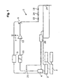
- FIG. 1 is a block diagram of a circuit arrangement according to the invention
- FIG. 2 is a block diagram of a special embodiment of a circuit arrangement according to the invention.
- FIG. 3 is a flowchart to explain the method according to the invention.
- FIG. 4 is a flowchart to explain a special embodiment of the method according to the invention.
- FIG. 5 shows diagrams with experimental data for artificially interrupted voltage pulses.
- FIG. 1 shows a block diagram of a circuit arrangement 1 according to the invention with an adjustment unit 2 for inputting parameters to be preset, a central controlling device 3 for controlling the circuit arrangement 1 , and a high-voltage power supply 5 .
- the high-voltage power supply 5 feeds a downstream storage device 7 , which can be a capacitor or group of capacitors, for example, which can be charged with a voltage U 1 .
- the storage device 7 is connected with a power semiconductor 9 to emit a voltage pulse (U 1 ) or discharge the storage device 7 .
- the power semiconductor 9 can be actuated, here via a potential divider stage 11 , by way of a voltage switch 13 via the controlling device 3 , a control unit 20 and a controller 4 .
- the storage device 7 is directly connected with the input of the power semiconductor 9 , wherein the power semiconductor 9 can, for example, consist of an IGBT.
- the term “power semiconductor” is also meant to encompass all other electronic components or component arrangements that can be used to switch voltages and currents that are to be switched with the necessary switching times.
- the output of the power semiconductor 9 is directly connected with a cuvette terminal 15 .
- the cuvette 24 is a reaction vessel used to hold an aqueous solution and the biomaterial to be treated and in which the electrical field is generated.
- a second cuvette terminal 18 is connected to ground via a resistor 19 .
- the resistor 19 is a measuring shunt, e.g., for use in measuring the voltage drop and routing it to the control unit 20 .
- the control unit 20 can terminate the voltage pulse via an switching device 21 by way of the potential divider stage 11 and voltage switch 13 .
- a disconnecting device (not shown here) arranged in the control unit 20 switches the switching device 21 in such a way as to terminate the discharge of the storage device 7 .
- the slope of the current strength rise can be measured in a very short time interval, and the voltage pulse can be terminated by the control unit 20 or by the disconnecting device if a preset limit has been exceeded (flank deactivation).
- the switching device 21 can be switched via the controller 4 , so that the latter can control the process of discharging the storage device 7 by switching the switching device 21 .
- the controller 4 can monitor the chronological progression of the respective voltage pulse, i.e., the time at which a pulse was terminated, and calculate the duration of the additional voltage pulse on the one hand, and trigger the additional voltage pulses by triggering the switching device 21 on the other.
- the discharge process is hereby controlled via the controller 4 , preferably indirectly via the control unit 20 .
- the controller 4 can directly control the switching device 21 .
- the low-ohm measuring resistor 19 lies behind the cuvette terminals 15 , 18 , and is wired to ground, making it possible to preclude the transmission of high-voltage pluses.
- the storage device 7 can encompass several capacitors with the required capacity and breakdown voltage, so that a correspondingly high charge can be stored and transmitted to the cuvette terminal 15 .
- FIG. 2 shows a block diagram of a special embodiment of a circuit arrangement 25 according to the invention, which essentially corresponds to the circuit arrangement 1 according to FIG. 1 , but differs in that it has an additional storage device 8 that can be charged with a voltage U 2 to emit a second voltage pulse. Therefore, this circuit arrangement 25 is suitable for applications in which two voltage pulses must be emitted in rapid succession. For example, it may be advantageous for the transfection of specific cell types to generate a short voltage pulse with a high field strength initially, followed immediately, preferably without any delay after termination of the first voltage pulse, by a second voltage pulse with a longer duration but a lower field strength.
- two high-voltage power supplies 5 , 6 each feed a downstream storage device 7 , 8 , which each can, for example, comprise a capacitor or group of capacitors, which is/are each connected with a power semiconductor 9 , 10 provided for emitting a voltage pulse or discharging the storage devices 7 , 8 .
- the power semiconductor 10 can here be actuated via the potential divider stage 12 by means of a voltage switch 14 via the controlling device 3 , a control unit 22 and the controller 4 .
- the storage devices 7 , 8 are directly connected with the inputs of the power semiconductors 9 , 10 , wherein the storage devices 7 , 8 can consist of one or more capacitors, depending on the used field strength and pulse duration.
- the power semiconductor 9 can consist of an IGBT
- the power semiconductor 10 can consist of a MOSFET.
- both power semiconductors 9 , 10 preferably consist of an IGBT.
- the output of the power semiconductor 10 is connected with the cuvette terminal 15 by means of a resistor 16 and a diode 17 , so that no pulse can flow back via the second power semiconductor 10 if both power semiconductors 9 , 10 are actuated simultaneously.
- the diode 17 is connected with the cuvette terminal 15 on the side of the cathode.
- a second control unit 22 can terminate actuation of the voltage switch 14 for the power semiconductor 10 via a switch 23 .
- the applied voltage is routed to the control unit 22 via the resistor 16 in order to cut off the power if a maximum current is exceeded. Because the resistor 16 is disposed directly in the high-voltage circuit, the switch 23 is located behind the potential divider stage 12 , so that no high-voltage pulses can get into the controlling device 3 and thus no danger is posed to the operating personnel.
- the circuit arrangement 25 use can be made of one or more high-voltage power supplies 5 , 6 with accompanying storage devices 7 , 8 and necessary potential divider stages 11 , 12 and voltage switches 13 , 14 for actuating the power semiconductors 9 , 10 .
- the storage devices 7 , 8 are here each equipped with one or more capacitors of the required capacity and breakdown voltage, so that a correspondingly high charge can be stored and transmitted to the cuvette terminal 15 .
- the circuit arrangement 25 matches the circuit arrangement 1 according to FIG. 1 exactly.
- FIG. 3 shows a schematic flowchart of the method according to a preferred embodiment of the invention.
- the necessary pulse parameters e.g., pulse duration T1 and field strength
- the routine e.g., by actuating a corresponding trigger key
- the pulse parameters for the selected program are first generated in step 30 .
- the ohm resistance of the cuvette is then determined by briefly applying a low voltage (e.g., 12 V) to the cuvette terminals, and then measuring the current (e.g., for 2 ms). As part of step 32 , it is determined whether this resistance lies within a preset window.
- a low voltage e.g. 12 V
- the routines are terminated by the error recovery routine 33 . If the resistance lies duly within the preset window, the storage device 7 according to FIGS. 1 and 2 is charged to the preset voltage U 1 in step 34 . Once the desired charging voltage has been reached, charging by the high-voltage power supply is terminated. The emission of the first voltage pulse is then initiated in step 35 by closing the power semiconductor 9 according to FIGS. 1 and 2 . This produces an electrical field in the cuvette, which accommodates the biomaterial to be treated. At the same time, the electrical parameters are monitored and tracked, e.g., the current rise via the control unit 20 according to FIGS. 1 and 2 , and the chronological progression of the voltage pulse via the controller 4 according to FIGS. 1 and 2 .
- the first voltage pulse is normally ended after a preset duration T1 which is processed in step 36 .
- the power semiconductor is opened in step 37 .
- the routine switches to step 38 .
- step 35 is once again called, thereby triggering an additional voltage pulse, wherein the controller 4 according to FIGS.
- FIG. 4 shows a flowchart to explain a special embodiment of the method according to the invention, in which two merging voltage pluses are emitted.
- a high-voltage pulse is ended after a preset period, and is immediately followed by a second pulse without interruption.
- the depicted method essentially corresponds to the method described on FIG. 34 , except for step 38 .
- the second storage device 8 according to FIG. 2 is also charged to the preset voltage in step 34 .
- the corresponding high-voltage power supply terminates the charging process.
- the second power semiconductor 10 according to FIG. 2 is already closed in step 37 shortly before the first semiconductor 9 according to FIG.
- the diode 17 according to FIG. 2 prevents a potentially higher voltage from being able to flow from the storage device 7 into the storage device 8 .
- the power semiconductor 10 subsequently remains closed (unless opened by an excessive current via the control unit 22 until a preset charge Q has flowed through the cuvette 24 according to FIG. 2 .
- the current flowing through the cuvette is measured and integrated in step 39 over preset time intervals (e.g., 1 ms).
- step 41 the prescribed setpoint charge has been reached (step 41 ) or a preset time has been exceeded (step 40 )
- the power semiconductor 10 is opened in step 42 , and the routine is ended.
- the capacity of the storage device 8 according to FIG. 2 is selected in such a way that the voltage gradually or slowly falls during the second pulse. If a disturbance prevents the prescribed setpoint charge from being reached even given a nearly completely discharged storage device, the process is terminated via the error recovery routine 43 after a correspondingly selected time limit has been exceeded.
- FIG. 5 shows diagrams of experimental data for artificially terminated voltage pulses.
- 1 ⁇ 10 6 K563 cells were introduced in a 100 ⁇ l solution of the Cell Line Nucleofector Kit R (amaxa GmbH), supplemented with 0.5 ⁇ g of pEGFP-C1 (Invitrogen) and subjected to a field of 5 kV/cm for varying times.
- the cells were subsequently placed in Iscove's modified Dulbecco's medium (Invitrogen) with 2 mM of GlutaMAX (Invitrogen), 100 ⁇ g/ml of Streptomycin, 100 U/ml of penicillin and 10% FCS (Sigma), and cultivated for 48 hours at 37° C.
- FIGS. 5 c and 5 d confirm the results of the tests depicted on FIGS. 5 a and 5 b ; wherein the transfection efficiencies are lower overall, so that larger fluctuations come about. It is here demonstrated as well that a terminated first voltage pulse can be successfully continued. In this case, the test result can be clearly improved given longer pauses if the selected overall duration Ts of the additional voltage pulses exceeds T1 ⁇ Tx.
Abstract
Description
- 1 Circuit arrangement
- 2 Adjustment unit
- 3 Controlling device
- 4 Controller
- 5 High-voltage power supply
- 6 High-voltage power supply
- 7 Storage device
- 8 Storage device
- 9 Power semiconductor
- 10 Power semiconductor
- 11 Potential divider stage
- 12 Potential divider stage
- 13 Voltage switch
- 14 Voltage switch
- 15 Cuvete terminal
- 16 Resistor
- 17 Diode
- 18 Cuvette terminal
- 19 Resistor
- 20 Control unit
- 21 Switching device
- 22 Control unit
- 23 Switch
- 24 Cuvette
- 25 Circuit arrangement
- 30 −
- 43 Steps
Claims (10)
Priority Applications (1)
| Application Number | Priority Date | Filing Date | Title |
|---|---|---|---|
| US12/766,273 US8058042B2 (en) | 2004-06-14 | 2010-04-23 | Method and circuit arrangement for treating biomaterial |
Applications Claiming Priority (3)
| Application Number | Priority Date | Filing Date | Title |
|---|---|---|---|
| EPEP04013843.0 | 2004-06-14 | ||
| EP04013843 | 2004-06-14 | ||
| EP04013843.0A EP1607484B1 (en) | 2004-06-14 | 2004-06-14 | Method and circuitry for treating biological material |
Related Child Applications (1)
| Application Number | Title | Priority Date | Filing Date |
|---|---|---|---|
| US12/766,273 Division US8058042B2 (en) | 2004-06-14 | 2010-04-23 | Method and circuit arrangement for treating biomaterial |
Publications (2)
| Publication Number | Publication Date |
|---|---|
| US20060094095A1 US20060094095A1 (en) | 2006-05-04 |
| US7732175B2 true US7732175B2 (en) | 2010-06-08 |
Family
ID=34925340
Family Applications (2)
| Application Number | Title | Priority Date | Filing Date |
|---|---|---|---|
| US11/151,643 Active 2028-11-19 US7732175B2 (en) | 2004-06-14 | 2005-06-14 | Method and circuit arrangement for treating biomaterial |
| US12/766,273 Active US8058042B2 (en) | 2004-06-14 | 2010-04-23 | Method and circuit arrangement for treating biomaterial |
Family Applications After (1)
| Application Number | Title | Priority Date | Filing Date |
|---|---|---|---|
| US12/766,273 Active US8058042B2 (en) | 2004-06-14 | 2010-04-23 | Method and circuit arrangement for treating biomaterial |
Country Status (3)
| Country | Link |
|---|---|
| US (2) | US7732175B2 (en) |
| EP (1) | EP1607484B1 (en) |
| ES (1) | ES2465467T3 (en) |
Cited By (1)
| Publication number | Priority date | Publication date | Assignee | Title |
|---|---|---|---|---|
| WO2019048689A1 (en) | 2017-09-11 | 2019-03-14 | Imba - Institut Für Molekulare Biotechnologie Gmbh | Tumor organoid model |
Families Citing this family (8)
| Publication number | Priority date | Publication date | Assignee | Title |
|---|---|---|---|---|
| CN101274120B (en) * | 2008-04-29 | 2013-03-13 | 圣太科医疗科技(上海)有限公司 | Bio-medical multi-way low voltage micro-electric field generator |
| WO2012098260A1 (en) | 2011-01-21 | 2012-07-26 | Axiogenesis Ag | A non-viral system for the generation of induced pluripotent stem (ips) cells |
| CN107429254B (en) | 2015-01-30 | 2021-10-15 | 加利福尼亚大学董事会 | Protein delivery in primary hematopoietic cells |
| WO2018047271A1 (en) * | 2016-09-08 | 2018-03-15 | 三菱電機株式会社 | Pulse discharge power supply and pulse discharge generating method |
| SE542514C2 (en) | 2017-07-28 | 2020-05-26 | Scandinavian Chemotech Ab | A pulse generating device for delivery of electrical pulses to a desired tissue of a mammal |
| EP4279085A1 (en) | 2022-05-20 | 2023-11-22 | Mnemo Therapeutics | Compositions and methods for treating a refractory or relapsed cancer or a chronic infectious disease |
| WO2024059618A2 (en) | 2022-09-13 | 2024-03-21 | Arsenal Biosciences, Inc. | Immune cells having co-expressed tgfbr shrnas |
| WO2024059824A2 (en) | 2022-09-16 | 2024-03-21 | Arsenal Biosciences, Inc. | Immune cells with combination gene perturbations |
Citations (40)
| Publication number | Priority date | Publication date | Assignee | Title |
|---|---|---|---|---|
| US3707974A (en) | 1970-12-11 | 1973-01-02 | W Raddi | Body organ stimulator with voltage converter |
| EP0113549A1 (en) | 1982-12-10 | 1984-07-18 | Trolex Products Limited | Impedance sensor |
| DE3718941A1 (en) | 1986-06-06 | 1988-02-04 | Bio Rad Laboratories | DEVICE AND METHOD FOR INITIATING HIGH VOLTAGE CURRENTS IN A CHEMICAL SOLUTION |
| WO1988002777A1 (en) | 1986-10-10 | 1988-04-21 | Electropore Inc. | Process for extracting cell contents |
| EP0283700A2 (en) | 1987-03-18 | 1988-09-28 | Heinz Doevenspeck | Process and apparatus for the treatment of compounds and/or micro-organisms with electrical impulses |
| DE3724291A1 (en) | 1987-07-22 | 1989-02-02 | Siemens Ag | Regulated short-term energy source |
| US4849355A (en) | 1985-01-08 | 1989-07-18 | Wong Tai Kin | Method of transferring genes into cells |
| JPH0235071A (en) | 1988-07-22 | 1990-02-05 | Shimadzu Corp | Time constant controlling type cell electrostimulator |
| US4906576A (en) | 1986-05-09 | 1990-03-06 | Electropore, Inc. | High speed, high power apparatus for vesicle prealignment, poration, loading and fusion in uniform electric fields and method therefor |
| EP0362758A2 (en) | 1988-10-05 | 1990-04-11 | HAPGOOD, C.V., a Netherlands Antilles Limited Partnership | Electro-insertion of proteins into animal cell membranes |
| US4923814A (en) | 1986-05-09 | 1990-05-08 | Electropore, Inc. | High speed, high power apparatus for vesicle prealignment, poration, loading and fusion in uniform electric fields and method therefor |
| US4946793A (en) | 1986-05-09 | 1990-08-07 | Electropore, Inc. | Impedance matching for instrumentation which electrically alters vesicle membranes |
| US4959321A (en) | 1988-03-26 | 1990-09-25 | Preece Alan W | Cell fusion apparatus |
| JPH02303478A (en) | 1989-05-19 | 1990-12-17 | Kirin Brewery Co Ltd | Trans-genetic device |
| JPH03195485A (en) | 1989-12-25 | 1991-08-27 | Kazuo Yanagi | Electropolation device |
| WO1991018103A1 (en) | 1990-05-16 | 1991-11-28 | Scientific Equipment Design & Development S.C. | Method and device for making living cells permeable |
| US5098843A (en) | 1987-06-04 | 1992-03-24 | Calvin Noel M | Apparatus for the high efficiency transformation of living cells |
| WO1992006185A1 (en) | 1990-09-27 | 1992-04-16 | The United States Of America, Represented By The Secretary, U.S. Department Of Commerce | Method of electroporation using bipolar oscillating electric fields |
| US5128257A (en) | 1987-08-31 | 1992-07-07 | Baer Bradford W | Electroporation apparatus and process |
| US5232856A (en) | 1990-06-25 | 1993-08-03 | Firth Kevin L | Electroporation device |
| US5254081A (en) | 1991-02-01 | 1993-10-19 | Empi, Inc. | Multiple site drug iontophoresis electronic device and method |
| US5273525A (en) | 1992-08-13 | 1993-12-28 | Btx Inc. | Injection and electroporation apparatus for drug and gene delivery |
| US5422272A (en) | 1993-07-14 | 1995-06-06 | Andrew A. Papp | Improvements to apparatus and method for electroporation |
| EP0689289A2 (en) | 1994-06-16 | 1995-12-27 | Bio-Rad Laboratories, Inc. | Transfection high-voltage controller |
| WO1995035389A1 (en) | 1994-06-17 | 1995-12-28 | Nederlandse Organisatie Voor Toegepast-Natuurwetenschappelijk Onderzoek Tno | Method for introduction of genetic material into microorganisms and transformants obtained therewith |
| US5627023A (en) | 1993-03-29 | 1997-05-06 | Duke University | Suppressor of HIV replication and transcription |
| WO1998010515A1 (en) | 1996-09-09 | 1998-03-12 | Genetronics, Inc. | Electroporation employing user-configured pulses |
| US5905371A (en) | 1995-06-23 | 1999-05-18 | D.C. Transformation, Inc. | Sequential discharge and its use for rectification |
| WO1999036563A1 (en) | 1998-01-14 | 1999-07-22 | Emed Corporation | Electrically mediated cellular expression |
| US6008038A (en) | 1997-03-21 | 1999-12-28 | Eppendorf-Netheler-Hinz Gmbh | Method and a circuit arrangement for the electropermeation of living cells |
| US6040184A (en) | 1998-10-09 | 2000-03-21 | Stratagene | Method for more efficient electroporation |
| US6103084A (en) | 1995-06-06 | 2000-08-15 | Eppendorf Netheler-Hinz Gmbh | Apparatus for electroporation |
| US6150148A (en) | 1998-10-21 | 2000-11-21 | Genetronics, Inc. | Electroporation apparatus for control of temperature during the process |
| US6258592B1 (en) | 1999-06-14 | 2001-07-10 | Bio-Rad Laboratories, Inc. | Electroporation cell with arc prevention/reduction |
| JP3195485B2 (en) | 1993-12-27 | 2001-08-06 | 大塚化学株式会社 | Method for producing flame retardant composition and method for flame retardation |
| WO2002086129A1 (en) | 2001-04-23 | 2002-10-31 | Amaxa Gmbh | Circuit arrangement for injecting nucleic acids and other biologically active molecules into the nucleus of higher eucaryontic cells using electrical current |
| US6521430B1 (en) | 1997-11-06 | 2003-02-18 | Cellectricon Ab | Method for electro-permeabilization of individual cellular and organellar structures and use thereof |
| WO2003050546A2 (en) | 2001-12-06 | 2003-06-19 | Bio-Rad Laboratories Inc. | Resistance circuit stabilization and pulse duration control systems for electroporation instruments |
| WO2003076006A2 (en) | 2002-03-07 | 2003-09-18 | Advisys, Inc. | Electrode assembly for constant-current electroporation and use |
| US6632672B2 (en) | 1998-08-19 | 2003-10-14 | The Board Of Trustees Of The Leland Stanford Junior University | Methods and compositions for genomic modification |
Family Cites Families (1)
| Publication number | Priority date | Publication date | Assignee | Title |
|---|---|---|---|---|
| US5874046A (en) * | 1996-10-30 | 1999-02-23 | Raytheon Company | Biological warfare agent sensor system employing ruthenium-terminated oligonucleotides complementary to target live agent DNA sequences |
-
2004
- 2004-06-14 ES ES04013843.0T patent/ES2465467T3/en active Active
- 2004-06-14 EP EP04013843.0A patent/EP1607484B1/en active Active
-
2005
- 2005-06-14 US US11/151,643 patent/US7732175B2/en active Active
-
2010
- 2010-04-23 US US12/766,273 patent/US8058042B2/en active Active
Patent Citations (48)
| Publication number | Priority date | Publication date | Assignee | Title |
|---|---|---|---|---|
| US3707974A (en) | 1970-12-11 | 1973-01-02 | W Raddi | Body organ stimulator with voltage converter |
| EP0113549A1 (en) | 1982-12-10 | 1984-07-18 | Trolex Products Limited | Impedance sensor |
| US4849355A (en) | 1985-01-08 | 1989-07-18 | Wong Tai Kin | Method of transferring genes into cells |
| US4923814A (en) | 1986-05-09 | 1990-05-08 | Electropore, Inc. | High speed, high power apparatus for vesicle prealignment, poration, loading and fusion in uniform electric fields and method therefor |
| US4906576A (en) | 1986-05-09 | 1990-03-06 | Electropore, Inc. | High speed, high power apparatus for vesicle prealignment, poration, loading and fusion in uniform electric fields and method therefor |
| US4946793A (en) | 1986-05-09 | 1990-08-07 | Electropore, Inc. | Impedance matching for instrumentation which electrically alters vesicle membranes |
| DE3718941A1 (en) | 1986-06-06 | 1988-02-04 | Bio Rad Laboratories | DEVICE AND METHOD FOR INITIATING HIGH VOLTAGE CURRENTS IN A CHEMICAL SOLUTION |
| US4750100A (en) | 1986-06-06 | 1988-06-07 | Bio-Rad Laboratories | Transfection high voltage controller |
| WO1988002777A1 (en) | 1986-10-10 | 1988-04-21 | Electropore Inc. | Process for extracting cell contents |
| EP0283700A2 (en) | 1987-03-18 | 1988-09-28 | Heinz Doevenspeck | Process and apparatus for the treatment of compounds and/or micro-organisms with electrical impulses |
| US5098843A (en) | 1987-06-04 | 1992-03-24 | Calvin Noel M | Apparatus for the high efficiency transformation of living cells |
| DE3724291A1 (en) | 1987-07-22 | 1989-02-02 | Siemens Ag | Regulated short-term energy source |
| US5128257A (en) | 1987-08-31 | 1992-07-07 | Baer Bradford W | Electroporation apparatus and process |
| US4959321A (en) | 1988-03-26 | 1990-09-25 | Preece Alan W | Cell fusion apparatus |
| JPH0235071A (en) | 1988-07-22 | 1990-02-05 | Shimadzu Corp | Time constant controlling type cell electrostimulator |
| EP0362758A2 (en) | 1988-10-05 | 1990-04-11 | HAPGOOD, C.V., a Netherlands Antilles Limited Partnership | Electro-insertion of proteins into animal cell membranes |
| JPH02303478A (en) | 1989-05-19 | 1990-12-17 | Kirin Brewery Co Ltd | Trans-genetic device |
| JPH03195485A (en) | 1989-12-25 | 1991-08-27 | Kazuo Yanagi | Electropolation device |
| WO1991018103A1 (en) | 1990-05-16 | 1991-11-28 | Scientific Equipment Design & Development S.C. | Method and device for making living cells permeable |
| US5232856A (en) | 1990-06-25 | 1993-08-03 | Firth Kevin L | Electroporation device |
| WO1992006185A1 (en) | 1990-09-27 | 1992-04-16 | The United States Of America, Represented By The Secretary, U.S. Department Of Commerce | Method of electroporation using bipolar oscillating electric fields |
| US5254081A (en) | 1991-02-01 | 1993-10-19 | Empi, Inc. | Multiple site drug iontophoresis electronic device and method |
| US5273525A (en) | 1992-08-13 | 1993-12-28 | Btx Inc. | Injection and electroporation apparatus for drug and gene delivery |
| US5627023A (en) | 1993-03-29 | 1997-05-06 | Duke University | Suppressor of HIV replication and transcription |
| US5422272A (en) | 1993-07-14 | 1995-06-06 | Andrew A. Papp | Improvements to apparatus and method for electroporation |
| JP3195485B2 (en) | 1993-12-27 | 2001-08-06 | 大塚化学株式会社 | Method for producing flame retardant composition and method for flame retardation |
| EP0689289A2 (en) | 1994-06-16 | 1995-12-27 | Bio-Rad Laboratories, Inc. | Transfection high-voltage controller |
| US5642035A (en) | 1994-06-16 | 1997-06-24 | Bio-Rad Laboratories | Transfection high-voltage controller |
| WO1995035389A1 (en) | 1994-06-17 | 1995-12-28 | Nederlandse Organisatie Voor Toegepast-Natuurwetenschappelijk Onderzoek Tno | Method for introduction of genetic material into microorganisms and transformants obtained therewith |
| US6103084A (en) | 1995-06-06 | 2000-08-15 | Eppendorf Netheler-Hinz Gmbh | Apparatus for electroporation |
| US5905371A (en) | 1995-06-23 | 1999-05-18 | D.C. Transformation, Inc. | Sequential discharge and its use for rectification |
| WO1998010515A1 (en) | 1996-09-09 | 1998-03-12 | Genetronics, Inc. | Electroporation employing user-configured pulses |
| US5869326A (en) | 1996-09-09 | 1999-02-09 | Genetronics, Inc. | Electroporation employing user-configured pulsing scheme |
| US6008038A (en) | 1997-03-21 | 1999-12-28 | Eppendorf-Netheler-Hinz Gmbh | Method and a circuit arrangement for the electropermeation of living cells |
| EP0866123B1 (en) | 1997-03-21 | 2005-03-16 | Eppendorf Ag | Method and circuit device for electropermeation or electroporation of living cells |
| US6521430B1 (en) | 1997-11-06 | 2003-02-18 | Cellectricon Ab | Method for electro-permeabilization of individual cellular and organellar structures and use thereof |
| WO1999036563A1 (en) | 1998-01-14 | 1999-07-22 | Emed Corporation | Electrically mediated cellular expression |
| US6632672B2 (en) | 1998-08-19 | 2003-10-14 | The Board Of Trustees Of The Leland Stanford Junior University | Methods and compositions for genomic modification |
| US6040184A (en) | 1998-10-09 | 2000-03-21 | Stratagene | Method for more efficient electroporation |
| US6150148A (en) | 1998-10-21 | 2000-11-21 | Genetronics, Inc. | Electroporation apparatus for control of temperature during the process |
| US6258592B1 (en) | 1999-06-14 | 2001-07-10 | Bio-Rad Laboratories, Inc. | Electroporation cell with arc prevention/reduction |
| EP1190075B1 (en) | 1999-06-14 | 2006-09-13 | Bio-Rad Laboratories, Inc. | Electroporation cell with arc prevention/reduction |
| WO2002086129A1 (en) | 2001-04-23 | 2002-10-31 | Amaxa Gmbh | Circuit arrangement for injecting nucleic acids and other biologically active molecules into the nucleus of higher eucaryontic cells using electrical current |
| US20040137603A1 (en) | 2001-04-23 | 2004-07-15 | Herbert Muller-Hartmann | Circuit arrangement for injecting nucleic acids and other biologically active molecules into the nucleus of higher eucaryontic cells using electrical current |
| EP1383901B1 (en) | 2001-04-23 | 2004-11-03 | Amaxa GmbH | Circuit arrangement for injecting nucleic acids and other biologically active molecules into the nucleus of higher eucaryontic cells using electrical current |
| WO2003050546A2 (en) | 2001-12-06 | 2003-06-19 | Bio-Rad Laboratories Inc. | Resistance circuit stabilization and pulse duration control systems for electroporation instruments |
| US20030139889A1 (en) | 2001-12-06 | 2003-07-24 | Bio-Rad Laboratories, Inc. | Resistance circuit stabilization and pulse duration control systems for electroporation instruments |
| WO2003076006A2 (en) | 2002-03-07 | 2003-09-18 | Advisys, Inc. | Electrode assembly for constant-current electroporation and use |
Non-Patent Citations (29)
| Title |
|---|
| Auer et al, "Dielectric breakdown of the red blood cell membrane and uptake of SV40 DNA and mammallan RNA," in Naturwissenschaften, vol. 63, pp. 391, 1976. |
| Bamberger et al: "Dissoclative Glucocorticotd Activity of Medroxyprogesterone Acetate in Normal Human Lymphocytes," in Journal of Clinical Endocrinology & Metabollsm, vol. 84, pp. 4055-4061, 1999. |
| Baubonis et al, "Genomic targetlng wilh purified Cre recombinase," in Nuclelo Acids Research, vol. 21, No. 9, pp. 2025-2029, May 1993. |
| Bertling et al: "Intranuclear uptake and persistance of biologlcally actlve DNA after electroporation of mammalian cells," in J. Biochern. Biophys, Methods, vol. 14(4), pp. 223-232, 1987. |
| Bertling: "Transfection of a DNA/protein complex into nuclel of mammallan cells using polyoma capslds and electroporation," in Biosci. Rep., vol. 7, No. 2, pp. 107-112, Feb. 1987. |
| Brown L.E. et al., Introduction of exogenous DNA into Chlamydomonas reinhardtii by electroporation. Mol Cell Biol. Apr;11(4):2328-32 (1991). |
| De Chasseval et al: "High level translent gene expression in human lymphoid cells by SV 40 large T antigen boost," in Nucleic Acids Res,, vol. 20 (2), pp. 245-250, 1992. |
| Edelstein et al: "Gene therapy clinical trials worldwide 1989-2004-an overview," in J. Gene Med., vol. 6, No. 6, pp. 597-602, Jun. 2004. |
| Eurogentec: "Easyjet Plus User's Manual," in Eurogantec, Liege, pp. 1-27 and 30-39, Jul. 10, 1992. |
| Kim et al: "Electroporation of extraneous proteins into CHO cells: increased efficacy by utilizing centrifugal force and microsecond electrical pulsea," in Exp, Cell Res., vol. 197(2). pp. 207-212, 1991. |
| Klenchin et al, "Electrically Induced DNA uptake by cells is a fast process Involving DNA electrophoresis," in Biophys. J., vol. 60, No. 4, pp. 804-811, Oct. 1991. |
| Krueger et al: "Transient Transfection of Oligodendrocyte Progenitors by Electroporatlon", in Neurochemical Research, vol. 23, pp. 421-426, 1998. |
| Leopold R.A. et al., Using electroporation and a slot cuvette to deliver plasmid DNA to insect embryos. Genet Anal. Mar;12(5-6):197-200 (1996). |
| Luo et al:"Synthetic DNA delivery systems" in Nature Biotechnology, vol. 18, No. 1, pp. 33-37, Jan. 2000. |
| Lurquin: "Gene transfer by electroporation" in Mol. Biotechnol., vol. 7(1), pp. 5-35, Feb. 1997. |
| Marechal et al.: "Mapplng EBNA-1 domains Involved in binding to metaphase chromosomes" in J. Virol., vol. 73, pp. 4385-4392, 1999. |
| Neumann et al.: "Gene transfer Into mouse lyoms cells by electroporation in high electric fields" in The EMBO Journal, vol. 1(7), pp. 841-845, 1982. |
| Neumann et al: "Permeabillty changes induced by electric Impulses in vesicular membranes" in J. Membrane Biol., vol. 10, pp. 279-290, 1972. |
| Palu et al.: "In pursuit of new developments for gene therapy of human diseases" in J. Biotechnol., vol. 68, No. 1, pp. 1-13, Feb. 1999. |
| Pliquett et al.: "Determination of the electric field and anomalous heating caused by exponential pulses with aluminum elctrodes in electroporatlon experiments" in Bioelectrochemistry and Bioenergetics, vol. 39(1), pp. 39-53, 1996. |
| Potter et al.: "Enhancer-dependent expression of human kappa Immunoglobulin genes Introduced into mouse pre-B lymphocytes by electroporation" in Proc. Natl Acad. Sci. USA. vol. 81(22), pp. 7161-7165, 1984. |
| Ratajczak et al.: "Heterogeneous Populations of Bone Marrow Stem Cells-Are We Spotting on the Same Cells from the Different Angles?" in Folia Histochemica Et Cytobiologica, vol. 42, No. 3, pp. 139-146, 2004. |
| Rols et al.: "Ionlo-strength modulatlon of eletrically Induced permeabilization and associated fuslon of mammallan cells" in Eur. J. Biochem. vol. 178, pp. 109-115, 1989. |
| Satoh et al.: "Successful transfer of ADA gene in vitro Into human peripheral blood CD34+ cells by transfooting EBV-based episomal vectors" in FEBS Lett., vol. 441, No. 1, pp. 39-42, Dec. 1998. |
| Schwachtgen et al.: "Optimization of the transfection of hurnan endothelial cells by electroporatlon" in Biotechniques. vol. 17(5), pp. 880-887, 1994. |
| Sukharev S.I. et al., Electroporation and electrophoretic DNA transfer into cells. The effect of DNA interaction with electropores. Biophysical Journal, vol. 63, 1320-1327 (1992). |
| Verma et al.: "Gene therapy-promises, problems and prospects" in Nature, vol. 389. No. 6648, pp. 239-242, Sep. 1997. |
| Watanabe et al.: "Calcium phosphato-modlated transfection of primary cultured brain neurons using GFP expression as a marker. application for single neuron electrophysiology," in Neuroscience Rasearch, vol. 33, pp. 71-78, 1999. |
| Zimmermann et al.: "Cells with manipulated functlons: new perspectives for cell biology, medicine and technology," in Angew. Chem. Int. Ed. Engl., vol. 20, pp. 325-344, 1981. |
Cited By (1)
| Publication number | Priority date | Publication date | Assignee | Title |
|---|---|---|---|---|
| WO2019048689A1 (en) | 2017-09-11 | 2019-03-14 | Imba - Institut Für Molekulare Biotechnologie Gmbh | Tumor organoid model |
Also Published As
| Publication number | Publication date |
|---|---|
| EP1607484A1 (en) | 2005-12-21 |
| US20100267106A1 (en) | 2010-10-21 |
| US20060094095A1 (en) | 2006-05-04 |
| US8058042B2 (en) | 2011-11-15 |
| ES2465467T3 (en) | 2014-06-05 |
| EP1607484B1 (en) | 2014-04-02 |
Similar Documents
| Publication | Publication Date | Title |
|---|---|---|
| US8058042B2 (en) | Method and circuit arrangement for treating biomaterial | |
| AU2007202279B2 (en) | Method for introducing biologically active molecules into the nucleus of eukaryotic cells using electric current | |
| EP1673140B1 (en) | Constant current electroporation device | |
| CA2670933C (en) | Multi-channel electroporation system | |
| US20040167458A1 (en) | Electrode assembly for constant-current electroporation and use | |
| AU2009251157B2 (en) | Electrode assembly for constant-current electroporation and use | |
| JPH1118770A (en) | Electroporation of cell and circuit | |
| CN113088444A (en) | Electric pulse generation system using capacitive coupling | |
| US8248050B2 (en) | Multi-channel low voltage micro-electric-field generator | |
| US6103084A (en) | Apparatus for electroporation | |
| KR20070074571A (en) | Method and device for batteries | |
| US20210371796A1 (en) | Control of Cell Electroporation | |
| US10421956B2 (en) | Electric pulse generation systems using capacitive coupling | |
| CN114978117A (en) | High voltage pulse generator for electroporation | |
| CN110661442A (en) | Charging and discharging circuit for electrotransformation instrument |
Legal Events
| Date | Code | Title | Description |
|---|---|---|---|
| AS | Assignment |
Owner name: AMAXA GMBH,GERMANY Free format text: ASSIGNMENT OF ASSIGNORS INTEREST;ASSIGNOR:MUELLER-HARTMANN, HERBERT;REEL/FRAME:017094/0702 Effective date: 20050829 Owner name: AMAXA GMBH, GERMANY Free format text: ASSIGNMENT OF ASSIGNORS INTEREST;ASSIGNOR:MUELLER-HARTMANN, HERBERT;REEL/FRAME:017094/0702 Effective date: 20050829 |
|
| AS | Assignment |
Owner name: AMAXA AG, GERMANY Free format text: CHANGE OF LEGAL FORM;ASSIGNOR:AMAXA GMBH;REEL/FRAME:019813/0622 Effective date: 20070327 Owner name: AMAXA AG,GERMANY Free format text: CHANGE OF LEGAL FORM;ASSIGNOR:AMAXA GMBH;REEL/FRAME:019813/0622 Effective date: 20070327 |
|
| AS | Assignment |
Owner name: LONZA COLOGNE AG, GERMANY Free format text: CHANGE OF NAME;ASSIGNOR:AMAXA AG;REEL/FRAME:022846/0012 Effective date: 20081013 Owner name: LONZA COLOGNE AG,GERMANY Free format text: CHANGE OF NAME;ASSIGNOR:AMAXA AG;REEL/FRAME:022846/0012 Effective date: 20081013 |
|
| STCF | Information on status: patent grant |
Free format text: PATENTED CASE |
|
| AS | Assignment |
Owner name: LONZA COLOGNE GMBH, GERMANY Free format text: CHANGE OF LEGAL FORM;ASSIGNOR:LONZA COLOGNE AG;REEL/FRAME:025741/0888 Effective date: 20100818 |
|
| AS | Assignment |
Owner name: LONZA COLOGNE GMBH, GERMANY Free format text: CHANGE OF LEGAL FORM;ASSIGNOR:LONZA COLOGNE AG;REEL/FRAME:026276/0125 Effective date: 20100818 |
|
| FPAY | Fee payment |
Year of fee payment: 4 |
|
| MAFP | Maintenance fee payment |
Free format text: PAYMENT OF MAINTENANCE FEE, 8TH YEAR, LARGE ENTITY (ORIGINAL EVENT CODE: M1552) Year of fee payment: 8 |
|
| MAFP | Maintenance fee payment |
Free format text: PAYMENT OF MAINTENANCE FEE, 12TH YEAR, LARGE ENTITY (ORIGINAL EVENT CODE: M1553); ENTITY STATUS OF PATENT OWNER: LARGE ENTITY Year of fee payment: 12 |