US7585734B2 - Method of fabricating multi-gate transistor and multi-gate transistor fabricated thereby - Google Patents
Method of fabricating multi-gate transistor and multi-gate transistor fabricated thereby Download PDFInfo
- Publication number
- US7585734B2 US7585734B2 US12/074,580 US7458008A US7585734B2 US 7585734 B2 US7585734 B2 US 7585734B2 US 7458008 A US7458008 A US 7458008A US 7585734 B2 US7585734 B2 US 7585734B2
- Authority
- US
- United States
- Prior art keywords
- layer
- gate electrode
- forming
- sacrificial layer
- active pattern
- Prior art date
- Legal status (The legal status is an assumption and is not a legal conclusion. Google has not performed a legal analysis and makes no representation as to the accuracy of the status listed.)
- Expired - Fee Related
Links
- 238000004519 manufacturing process Methods 0.000 title claims abstract description 13
- 238000000034 method Methods 0.000 claims abstract description 62
- 239000000758 substrate Substances 0.000 claims abstract description 33
- 125000006850 spacer group Chemical group 0.000 claims description 63
- 230000008569 process Effects 0.000 claims description 41
- VYPSYNLAJGMNEJ-UHFFFAOYSA-N Silicium dioxide Chemical compound O=[Si]=O VYPSYNLAJGMNEJ-UHFFFAOYSA-N 0.000 claims description 28
- 238000005468 ion implantation Methods 0.000 claims description 28
- 238000005498 polishing Methods 0.000 claims description 26
- 239000000377 silicon dioxide Substances 0.000 claims description 14
- 229910052681 coesite Inorganic materials 0.000 claims description 13
- 229910052906 cristobalite Inorganic materials 0.000 claims description 13
- 229910052682 stishovite Inorganic materials 0.000 claims description 13
- 229910052905 tridymite Inorganic materials 0.000 claims description 13
- WGTYBPLFGIVFAS-UHFFFAOYSA-M tetramethylammonium hydroxide Chemical compound [OH-].C[N+](C)(C)C WGTYBPLFGIVFAS-UHFFFAOYSA-M 0.000 claims description 12
- 238000001039 wet etching Methods 0.000 claims description 12
- 238000000059 patterning Methods 0.000 claims description 11
- 239000000463 material Substances 0.000 claims description 10
- 229910004541 SiN Inorganic materials 0.000 claims description 9
- 229910052814 silicon oxide Inorganic materials 0.000 claims description 9
- 229910021417 amorphous silicon Inorganic materials 0.000 claims description 8
- 238000005530 etching Methods 0.000 claims description 8
- 150000002500 ions Chemical class 0.000 claims description 8
- XUIMIQQOPSSXEZ-UHFFFAOYSA-N Silicon Chemical compound [Si] XUIMIQQOPSSXEZ-UHFFFAOYSA-N 0.000 claims description 7
- 229910052710 silicon Inorganic materials 0.000 claims description 7
- 239000010703 silicon Substances 0.000 claims description 7
- 239000012212 insulator Substances 0.000 claims description 5
- 239000000126 substance Substances 0.000 claims description 4
- XLYOFNOQVPJJNP-UHFFFAOYSA-N water Substances O XLYOFNOQVPJJNP-UHFFFAOYSA-N 0.000 claims description 4
- GRYLNZFGIOXLOG-UHFFFAOYSA-N Nitric acid Chemical compound O[N+]([O-])=O GRYLNZFGIOXLOG-UHFFFAOYSA-N 0.000 claims description 3
- 239000011259 mixed solution Substances 0.000 claims description 3
- 229910017604 nitric acid Inorganic materials 0.000 claims description 3
- 239000000243 solution Substances 0.000 claims description 3
- 239000010410 layer Substances 0.000 description 197
- 229910021420 polycrystalline silicon Inorganic materials 0.000 description 20
- 229920005591 polysilicon Polymers 0.000 description 14
- 239000007789 gas Substances 0.000 description 11
- 239000004065 semiconductor Substances 0.000 description 11
- 238000005229 chemical vapour deposition Methods 0.000 description 8
- 238000000206 photolithography Methods 0.000 description 6
- 238000000231 atomic layer deposition Methods 0.000 description 5
- 229910052751 metal Inorganic materials 0.000 description 5
- 239000002184 metal Substances 0.000 description 5
- 229920002120 photoresistant polymer Polymers 0.000 description 5
- 125000004429 atom Chemical group 0.000 description 4
- 238000002513 implantation Methods 0.000 description 4
- 230000003647 oxidation Effects 0.000 description 4
- 238000007254 oxidation reaction Methods 0.000 description 4
- JBRZTFJDHDCESZ-UHFFFAOYSA-N AsGa Chemical compound [As]#[Ga] JBRZTFJDHDCESZ-UHFFFAOYSA-N 0.000 description 3
- 229910021419 crystalline silicon Inorganic materials 0.000 description 3
- 238000004518 low pressure chemical vapour deposition Methods 0.000 description 3
- 239000000203 mixture Substances 0.000 description 3
- 229910021332 silicide Inorganic materials 0.000 description 3
- FVBUAEGBCNSCDD-UHFFFAOYSA-N silicide(4-) Chemical compound [Si-4] FVBUAEGBCNSCDD-UHFFFAOYSA-N 0.000 description 3
- ZOXJGFHDIHLPTG-UHFFFAOYSA-N Boron Chemical compound [B] ZOXJGFHDIHLPTG-UHFFFAOYSA-N 0.000 description 2
- PXHVJJICTQNCMI-UHFFFAOYSA-N Nickel Chemical compound [Ni] PXHVJJICTQNCMI-UHFFFAOYSA-N 0.000 description 2
- OAICVXFJPJFONN-UHFFFAOYSA-N Phosphorus Chemical compound [P] OAICVXFJPJFONN-UHFFFAOYSA-N 0.000 description 2
- MCMNRKCIXSYSNV-UHFFFAOYSA-N Zirconium dioxide Chemical compound O=[Zr]=O MCMNRKCIXSYSNV-UHFFFAOYSA-N 0.000 description 2
- 230000003213 activating effect Effects 0.000 description 2
- PNEYBMLMFCGWSK-UHFFFAOYSA-N aluminium oxide Inorganic materials [O-2].[O-2].[O-2].[Al+3].[Al+3] PNEYBMLMFCGWSK-UHFFFAOYSA-N 0.000 description 2
- 229910052785 arsenic Inorganic materials 0.000 description 2
- RQNWIZPPADIBDY-UHFFFAOYSA-N arsenic atom Chemical compound [As] RQNWIZPPADIBDY-UHFFFAOYSA-N 0.000 description 2
- 238000004380 ashing Methods 0.000 description 2
- 238000001505 atmospheric-pressure chemical vapour deposition Methods 0.000 description 2
- 230000015572 biosynthetic process Effects 0.000 description 2
- 229910052796 boron Inorganic materials 0.000 description 2
- 230000015556 catabolic process Effects 0.000 description 2
- 238000004140 cleaning Methods 0.000 description 2
- 229910017052 cobalt Inorganic materials 0.000 description 2
- 239000010941 cobalt Substances 0.000 description 2
- GUTLYIVDDKVIGB-UHFFFAOYSA-N cobalt atom Chemical compound [Co] GUTLYIVDDKVIGB-UHFFFAOYSA-N 0.000 description 2
- 229910052593 corundum Inorganic materials 0.000 description 2
- 238000006731 degradation reaction Methods 0.000 description 2
- 238000000151 deposition Methods 0.000 description 2
- 239000003989 dielectric material Substances 0.000 description 2
- 238000001312 dry etching Methods 0.000 description 2
- 230000000694 effects Effects 0.000 description 2
- 230000001747 exhibiting effect Effects 0.000 description 2
- 239000010408 film Substances 0.000 description 2
- 229910052732 germanium Inorganic materials 0.000 description 2
- GNPVGFCGXDBREM-UHFFFAOYSA-N germanium atom Chemical compound [Ge] GNPVGFCGXDBREM-UHFFFAOYSA-N 0.000 description 2
- CJNBYAVZURUTKZ-UHFFFAOYSA-N hafnium(IV) oxide Inorganic materials O=[Hf]=O CJNBYAVZURUTKZ-UHFFFAOYSA-N 0.000 description 2
- 239000007943 implant Substances 0.000 description 2
- 229910052698 phosphorus Inorganic materials 0.000 description 2
- 239000011574 phosphorus Substances 0.000 description 2
- 238000000623 plasma-assisted chemical vapour deposition Methods 0.000 description 2
- 239000002356 single layer Substances 0.000 description 2
- PBCFLUZVCVVTBY-UHFFFAOYSA-N tantalum pentoxide Inorganic materials O=[Ta](=O)O[Ta](=O)=O PBCFLUZVCVVTBY-UHFFFAOYSA-N 0.000 description 2
- 239000010409 thin film Substances 0.000 description 2
- 229910001845 yogo sapphire Inorganic materials 0.000 description 2
- OKTJSMMVPCPJKN-UHFFFAOYSA-N Carbon Chemical compound [C] OKTJSMMVPCPJKN-UHFFFAOYSA-N 0.000 description 1
- BPQQTUXANYXVAA-UHFFFAOYSA-N Orthosilicate Chemical compound [O-][Si]([O-])([O-])[O-] BPQQTUXANYXVAA-UHFFFAOYSA-N 0.000 description 1
- 239000004642 Polyimide Substances 0.000 description 1
- 229910003818 SiH2Cl2 Inorganic materials 0.000 description 1
- 229910000577 Silicon-germanium Inorganic materials 0.000 description 1
- 229910020750 SixGey Inorganic materials 0.000 description 1
- LEVVHYCKPQWKOP-UHFFFAOYSA-N [Si].[Ge] Chemical compound [Si].[Ge] LEVVHYCKPQWKOP-UHFFFAOYSA-N 0.000 description 1
- QVGXLLKOCUKJST-UHFFFAOYSA-N atomic oxygen Chemical compound [O] QVGXLLKOCUKJST-UHFFFAOYSA-N 0.000 description 1
- 230000004888 barrier function Effects 0.000 description 1
- 239000002041 carbon nanotube Substances 0.000 description 1
- 229910021393 carbon nanotube Inorganic materials 0.000 description 1
- 230000008859 change Effects 0.000 description 1
- 239000011248 coating agent Substances 0.000 description 1
- 238000000576 coating method Methods 0.000 description 1
- 239000002019 doping agent Substances 0.000 description 1
- 230000005684 electric field Effects 0.000 description 1
- 238000005516 engineering process Methods 0.000 description 1
- 238000007429 general method Methods 0.000 description 1
- 229910052735 hafnium Inorganic materials 0.000 description 1
- VBJZVLUMGGDVMO-UHFFFAOYSA-N hafnium atom Chemical compound [Hf] VBJZVLUMGGDVMO-UHFFFAOYSA-N 0.000 description 1
- 125000005843 halogen group Chemical group 0.000 description 1
- 239000012535 impurity Substances 0.000 description 1
- WPYVAWXEWQSOGY-UHFFFAOYSA-N indium antimonide Chemical compound [Sb]#[In] WPYVAWXEWQSOGY-UHFFFAOYSA-N 0.000 description 1
- 239000011810 insulating material Substances 0.000 description 1
- 239000011229 interlayer Substances 0.000 description 1
- 229910052451 lead zirconate titanate Inorganic materials 0.000 description 1
- 239000004973 liquid crystal related substance Substances 0.000 description 1
- 229910044991 metal oxide Inorganic materials 0.000 description 1
- 150000004706 metal oxides Chemical class 0.000 description 1
- 229910052759 nickel Inorganic materials 0.000 description 1
- 229910021334 nickel silicide Inorganic materials 0.000 description 1
- RUFLMLWJRZAWLJ-UHFFFAOYSA-N nickel silicide Chemical compound [Ni]=[Si]=[Ni] RUFLMLWJRZAWLJ-UHFFFAOYSA-N 0.000 description 1
- 150000004767 nitrides Chemical class 0.000 description 1
- 230000005693 optoelectronics Effects 0.000 description 1
- 229910052760 oxygen Inorganic materials 0.000 description 1
- 239000001301 oxygen Substances 0.000 description 1
- 229920001721 polyimide Polymers 0.000 description 1
- 230000009467 reduction Effects 0.000 description 1
- 230000007261 regionalization Effects 0.000 description 1
- 229910052594 sapphire Inorganic materials 0.000 description 1
- 239000010980 sapphire Substances 0.000 description 1
- 238000000926 separation method Methods 0.000 description 1
- 235000012239 silicon dioxide Nutrition 0.000 description 1
- -1 silk Substances 0.000 description 1
- 239000002002 slurry Substances 0.000 description 1
- 230000003068 static effect Effects 0.000 description 1
- WFKWXMTUELFFGS-UHFFFAOYSA-N tungsten Chemical compound [W] WFKWXMTUELFFGS-UHFFFAOYSA-N 0.000 description 1
- 229910052721 tungsten Inorganic materials 0.000 description 1
- 239000010937 tungsten Substances 0.000 description 1
- WQJQOUPTWCFRMM-UHFFFAOYSA-N tungsten disilicide Chemical compound [Si]#[W]#[Si] WQJQOUPTWCFRMM-UHFFFAOYSA-N 0.000 description 1
- 229910021342 tungsten silicide Inorganic materials 0.000 description 1
- 238000009279 wet oxidation reaction Methods 0.000 description 1
- GFQYVLUOOAAOGM-UHFFFAOYSA-N zirconium(iv) silicate Chemical compound [Zr+4].[O-][Si]([O-])([O-])[O-] GFQYVLUOOAAOGM-UHFFFAOYSA-N 0.000 description 1
Images


Classifications
-
- H—ELECTRICITY
- H01—ELECTRIC ELEMENTS
- H01L—SEMICONDUCTOR DEVICES NOT COVERED BY CLASS H10
- H01L21/00—Processes or apparatus adapted for the manufacture or treatment of semiconductor or solid state devices or of parts thereof
- H01L21/02—Manufacture or treatment of semiconductor devices or of parts thereof
- H01L21/04—Manufacture or treatment of semiconductor devices or of parts thereof the devices having at least one potential-jump barrier or surface barrier, e.g. PN junction, depletion layer or carrier concentration layer
- H01L21/18—Manufacture or treatment of semiconductor devices or of parts thereof the devices having at least one potential-jump barrier or surface barrier, e.g. PN junction, depletion layer or carrier concentration layer the devices having semiconductor bodies comprising elements of Group IV of the Periodic System or AIIIBV compounds with or without impurities, e.g. doping materials
-
- H—ELECTRICITY
- H01—ELECTRIC ELEMENTS
- H01L—SEMICONDUCTOR DEVICES NOT COVERED BY CLASS H10
- H01L29/00—Semiconductor devices adapted for rectifying, amplifying, oscillating or switching, or capacitors or resistors with at least one potential-jump barrier or surface barrier, e.g. PN junction depletion layer or carrier concentration layer; Details of semiconductor bodies or of electrodes thereof ; Multistep manufacturing processes therefor
- H01L29/66—Types of semiconductor device ; Multistep manufacturing processes therefor
- H01L29/68—Types of semiconductor device ; Multistep manufacturing processes therefor controllable by only the electric current supplied, or only the electric potential applied, to an electrode which does not carry the current to be rectified, amplified or switched
- H01L29/76—Unipolar devices, e.g. field effect transistors
- H01L29/772—Field effect transistors
- H01L29/78—Field effect transistors with field effect produced by an insulated gate
- H01L29/785—Field effect transistors with field effect produced by an insulated gate having a channel with a horizontal current flow in a vertical sidewall of a semiconductor body, e.g. FinFET, MuGFET
-
- H—ELECTRICITY
- H01—ELECTRIC ELEMENTS
- H01L—SEMICONDUCTOR DEVICES NOT COVERED BY CLASS H10
- H01L29/00—Semiconductor devices adapted for rectifying, amplifying, oscillating or switching, or capacitors or resistors with at least one potential-jump barrier or surface barrier, e.g. PN junction depletion layer or carrier concentration layer; Details of semiconductor bodies or of electrodes thereof ; Multistep manufacturing processes therefor
- H01L29/40—Electrodes ; Multistep manufacturing processes therefor
- H01L29/41—Electrodes ; Multistep manufacturing processes therefor characterised by their shape, relative sizes or dispositions
- H01L29/423—Electrodes ; Multistep manufacturing processes therefor characterised by their shape, relative sizes or dispositions not carrying the current to be rectified, amplified or switched
- H01L29/42312—Gate electrodes for field effect devices
- H01L29/42316—Gate electrodes for field effect devices for field-effect transistors
- H01L29/4232—Gate electrodes for field effect devices for field-effect transistors with insulated gate
- H01L29/42384—Gate electrodes for field effect devices for field-effect transistors with insulated gate for thin film field effect transistors, e.g. characterised by the thickness or the shape of the insulator or the dimensions, the shape or the lay-out of the conductor
-
- H—ELECTRICITY
- H01—ELECTRIC ELEMENTS
- H01L—SEMICONDUCTOR DEVICES NOT COVERED BY CLASS H10
- H01L29/00—Semiconductor devices adapted for rectifying, amplifying, oscillating or switching, or capacitors or resistors with at least one potential-jump barrier or surface barrier, e.g. PN junction depletion layer or carrier concentration layer; Details of semiconductor bodies or of electrodes thereof ; Multistep manufacturing processes therefor
- H01L29/66—Types of semiconductor device ; Multistep manufacturing processes therefor
- H01L29/66007—Multistep manufacturing processes
- H01L29/66075—Multistep manufacturing processes of devices having semiconductor bodies comprising group 14 or group 13/15 materials
- H01L29/66227—Multistep manufacturing processes of devices having semiconductor bodies comprising group 14 or group 13/15 materials the devices being controllable only by the electric current supplied or the electric potential applied, to an electrode which does not carry the current to be rectified, amplified or switched, e.g. three-terminal devices
- H01L29/66409—Unipolar field-effect transistors
- H01L29/66477—Unipolar field-effect transistors with an insulated gate, i.e. MISFET
- H01L29/66787—Unipolar field-effect transistors with an insulated gate, i.e. MISFET with a gate at the side of the channel
- H01L29/66795—Unipolar field-effect transistors with an insulated gate, i.e. MISFET with a gate at the side of the channel with a horizontal current flow in a vertical sidewall of a semiconductor body, e.g. FinFET, MuGFET
Definitions
- the present invention relates to a multi-gate transistor having a gate electrode with improved performance and a fabrication method thereof.
- Multi-gate transistors having a double-gate structure or a tri-gate structure have been developed for next-generation devices. These devices overcome degradation of performance due to a reduction of gate length (Lg) accompanied with scale down in devices (Kunihiro Suzuki et al., IEEE 1993 “Scaling Theory for Double-Gate SOI MOSFETs”; Robert Chau, SSDM 2002, “Advanced Depleted-Substrate Transistors: Single-Gate, Double-Gate and Tri-Gate”; Z.
- a multi-gate transistor having a double-gate or tri-gate structure has a higher tolerance on the thickness (Tsi) of a fully depleted region compared with a single-gate transistor.
- Such a general multi-gate transistor structure includes an active pattern formed by patterning a single crystalline silicon body on an insulating layer of a silicon-on-insulator (SOI) wafer and a gate electrode formed on a side and/or an upper surface of the active pattern.
- SOI silicon-on-insulator
- an active pattern is formed by patterning a silicon body formed on an insulating layer.
- Polysilicon for forming a gate electrode is deposited on a lateral surface and/or an upper surface of the active pattern.
- the underlying active pattern makes the entire surface of polysilicon deposited uneven.
- a planarizing process using chemical mechanical polishing (CMP) is additionally performed after depositing a thick layer of polysilicon.
- the thickness of polysilicon deposited is not uniform, resulting in a deviation in the thickness of polysilicon deposited throughout the surface.
- a deviation in the thickness of polysilicon polished throughout the surface may also be generated.
- the deviation in the thickness of polysilicon makes it difficult to control the thickness of the gate electrode.
- use of conventional CMP may cause a thickness deviation of several hundred angstroms across the surface of deposited polysilicon.
- it is difficult to control the thickness of a gate electrode structure ultimately resulting in a degradation of electrical characteristics of the transistor.
- the present invention provides a method of fabricating a multi-gate transistor having improved performance, in which a profile of a gate electrode formed on a gate insulating layer of the multi-gate transistor can be controlled in a stable manner.
- a method of fabricating a multi-gate transistor including forming an active pattern on a substrate, the active pattern having two or more surfaces on which channel regions are to be formed, forming a gate insulating layer on the channel regions, and forming a patterned gate electrode on the gate insulating layer while maintaining a shape conformal to the active pattern.
- forming the sacrificial layer comprises: forming the sacrificial layer on the entire surface of the resulting structure having the conductive layer; and filling the step of the conformally formed conductive layer by planarizing the sacrificial layer.
- the sacrificial layer is an amorphous silicon layer.
- Planarizing the sacrificial layer can include using a chemical mechanical polishing (CMP) process.
- CMP chemical mechanical polishing
- a polishing stop layer is formed on the conductive layer after the conductive layer is formed.
- the polishing stop layer can be formed of a material selected from the group consisting of SiO 2 , SiN, SiON, and a combination thereof.
- a first spacer is formed on the gate electrode and the lateral surfaces of the sacrificial layer remaining on the gate electrode, wherein in the removing of the sacrificial layer, the first spacer formed on the lateral surface of the sacrificial layer is removed together with the sacrificial layer so that the first spacer remains on the lateral surfaces of the gate electrode.
- the first spacer can be formed at a temperature of 550 degrees C. or less.
- the first spacer can be formed of a material selected from the group consisting of SiO 2 , SiN, SiON, and a combination thereof.
- shallow low-concentration ion implantation is performed by implanting ions into the active pattern using the gate electrode and the first spacer as ion-implantation masks; a second spacer is formed on the lateral surfaces of the first spacer; and deep high-concentration ion implantation is performed by implanting ions into the active pattern using the first and second spacers and the gate electrode as ion-implantation masks.
- forming the active pattern comprises: preparing a silicon-on-insulator (SOI) wafer; and forming the active pattern by patterning a silicon layer of the SOI wafer.
- forming the active pattern includes forming a plurality of active patterns on the substrate, the active patterns having two or more surfaces on which the channel regions are to be formed.
- the height of the gate electrode is in a range of 500-1,000 ⁇ .
- the active pattern is a patterned silicon layer of an SOI wafer.
- the active pattern includes a plurality of active patterns having two or more surfaces on which channel regions are to be formed.
- FIG. 1B is a cross-sectional view taken along a line X-X′ shown in FIG. 1A .
- FIG. 1C is a cross-sectional view taken along a line Y-Y′ shown in FIG. 1A .
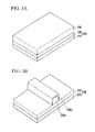
- FIG. 2 is a perspective view showing a structure of a multi-gate transistor according to another embodiment of the present invention.
- FIGS. 3A through 3J are cross-sectional views successively illustrating steps of a method of fabricating a multi-gate transistor according to the present invention.
- a fabrication method of a multi-gate transistor capable of controlling a gate electrode profile with stable profile reproducibility and a multi-gate transistor fabricated thereby are provided.
- an active pattern is formed on a substrate, the active pattern having two or more surfaces on which channel regions are to be formed and a gate insulating layer is formed on the channel regions.
- a conductive layer for a gate electrode is formed on the gate insulating layer and a sacrificial layer is formed thereon.
- the sacrificial layer is planarized for performing a photolithography process on the sacrificial layer and the conductive layer for the gate electrode.
- CMP chemical mechanical polishing
- a polishing stop layer functioning as a stop layer against CMP is formed between the conductive layer for the gate electrode and the sacrificial layer.
- Multi-gate transistors to which a method of fabricating an active structure according to the present invention can be applied include a double-gate transistor having channel regions on two surfaces of an active pattern and a tri-gate transistor having channel regions on three surfaces of an active pattern.
- These multi-gate transistors of the invention also include transistors used in highly integrated semiconductor memory devices such as a dynamic random access memory (DRAM) device, a static RAM (SRAM) device, a flash memory device, a ferroelectric RAM (FRAM) device, a magnetic RAM (MRAM) device, and a parameter RAM (PRAM) device, micro electro mechanical system (MEMS) devices, optoelectronic devices, display devices, and processors such as a central processing unit (CPU) and a digital signal processor (DSP).
- DRAM dynamic random access memory
- SRAM static RAM
- FRAM ferroelectric RAM
- MRAM magnetic RAM
- PRAM parameter RAM
- MEMS micro electro mechanical system
- optoelectronic devices optoelectronic devices
- display devices and processors
- processors such as a central processing unit (CPU) and a digital signal processor (DSP).
- DSP digital signal processor
- FIGS. 1A through 3J preferred embodiments of the present invention will be described in detail with reference to FIGS. 1A through 3J .
- FIG. 1A is a perspective view showing a structure of a multi-gate transistor 100 according to one embodiment of the present invention
- FIG. 1B is a cross-sectional view taken along a line X-X′ in FIG. 1A
- FIG. 1C is a cross-sectional view taken along a line Y-Y′ in FIG. 1A .
- the multi-gate transistor 100 includes an active pattern 230 a formed on a substrate 215 , the active pattern 230 a having two or more surfaces on which channel regions are to be formed, a gate insulating layer 240 a formed on the active pattern 230 a , a gate electrode 250 a formed conformally on the gate insulating layer 240 a according to a shape of the active pattern 230 a , and a source/drain region 235 formed on the active patterns located in both lateral surfaces of the gate electrode 250 a.
- the active pattern 230 a may be formed of a semiconductor material.
- the active pattern 230 a may be formed of silicon (Si), germanium (Ge), silicon germanium (Si x Ge y ), gallium arsenic (GaAs), InSb, GaP and carbon nanotube, and the present invention is not limited thereto.
- an ideal single crystalline film be used as the active pattern 230 a .
- the multi-gate transistor 100 can be used in a high-speed operation device such as a microprocessor.
- a device is not required to meet strict specification requirements, like a liquid crystal display (LCD), a polycrystalline film can be used as the active pattern 230 a.
- LCD liquid crystal display
- the active pattern 230 a has a lower surface 234 formed at a portion contacting the substrate 215 , a pair of lateral surfaces 231 and 233 formed at opposite sides of the lower surface 234 , and an upper surface 232 opposite to and facing the lower surface 234 .
- Channel regions are formed on at least two among three surfaces including the lower surface 234 and the lateral surfaces 231 and 233 of the active pattern 230 a.
- the gate insulating layer 240 a may be formed using an oxide layer, a thermally grown silicon dioxide layer, silk, polyimide, or a high dielectric material.
- the oxide layer may be formed using dry etch using O 2 gas at a temperature of 1000-1100° C., wet etch in an atmosphere of water vapor at a temperature of 1000-1100° C., HCl oxidation using a mixture gas of O 2 gas and HCl gas, oxidation using a mixture gas of O 2 gas and C 2 H 3 Cl 3 gas, oxidation using a mixture gas of O 2 gas and C 2 H 2 Cl 2 gas, or the like.
- the gate insulating layer 240 a is formed to a thickness of 5-50 ⁇ .
- a material having a higher dielectric constant (k) is required, for example, HfO 2 , Ta 2 O 5 , Al 2 O 3 , PZT, or the like.
- the gate electrode 250 a is formed on the gate insulating layer 240 a . It is preferable that the gate electrode 250 a is formed on the gate insulating layer 240 a formed on three surfaces of the active pattern 230 a .
- the gate electrode conducting layer 250 a may be formed by using only a doped polysilicon layer or a metal layer, by sequentially stacking a doped polysilicon layer and a metal layer, or by sequentially stacking a doped polysilicon layer and a metal silicide layer.
- the metal layer is formed of a tungsten layer, a cobalt layer, or a nickel layer.
- Suitable examples of the metal silicide layer include a tungsten silicide layer, a cobalt silicide layer, and a nickel silicide layer.
- the doped polysilicon layer that is widely used at present is formed by LPCVD using SiH 2 Cl 2 and PH 3 gas.
- the gate electrode 250 a is conformally formed along a step of the active pattern 230 a.
- three channels and three gates g 1 , g 2 and g 3 are formed by the gate insulating layer 240 a surrounding the upper surface 232 and the lateral surfaces 231 and 233 of the active pattern 230 a and the gate electrode 250 a formed on the gate insulating layer 240 a .
- Three channels are formed on the upper surface 232 and the lateral surfaces 231 and 233 of the active pattern 230 a .
- the gate width of the multi-gate transistor 100 is equal to the sum of the widths of three channels. That is, the gate width of the multi-gate transistor 100 is equal to the sum of the heights of both lateral surfaces 231 and 233 and the width of the upper surface 232 of the active pattern 230 a.
- FIG. 2 is a perspective view showing a structure of a multi-gate transistor according to another embodiment of the present invention.
- the gate width of a multi-gate transistor 150 can be increased by forming a single gate electrode 170 on a plurality of active patterns 160 a , 160 b and 160 c .
- reference numeral 160 denotes a source/drain region to which the plurality of active patterns 160 a , 160 b and 160 c are connected.
- the gate electrode 170 of the multi-gate transistor 150 is conformally formed along steps of the plurality of underlying active patterns 160 a , 160 b and 160 c .
- a first spacer 180 and a second spacer 190 formed in a side of the gate electrode 170 are conformally formed along the steps of the plurality of underlying active patterns 160 a , 160 b and 160 c.
- the gate electrode 170 shown in FIG. 2 performs the same function as the above-described gate electrode 250 a of FIGS. 1A through 1C and can be fabricated by the same fabrication method as the gate electrode 250 a .
- the first spacer 180 and the second spacer 190 shown in FIG. 2 may perform the same functions as a first spacer 285 and second spacer 290 of FIGS. 1A through 1C and can be fabricated by the same fabrication method as the first spacer 285 and the second spacer 290 , respectively, which will be described below.
- the upper surface 232 and the lateral surfaces 231 and 233 of the active pattern 230 a can be formed to a thickness of 500 ⁇ or less.
- the upper surface 232 of the active pattern 230 a is formed to a width of about 400 ⁇ and the lateral surfaces 231 and 233 of the active pattern 230 a are formed to a length of about 350 ⁇ .
- a height Hg of the gate electrode 250 a shown in FIG. 1B is larger than the lengths of the lateral surfaces 231 and 233 of the active pattern 230 a .
- the height Hg of the gate electrode 250 a is in a range of 500-1,000 ⁇ . More preferably, the height Hg of the gate electrode 250 a is in a range of 750-850 ⁇ .
- the gate length of the multi-gate transistor 100 corresponds to a distance Lg between lateral surfaces 251 and 252 of the gate electrode 250 a . It is preferable that the gate length Lg is formed to a thickness of 600 ⁇ or less. Referring to FIGS. 1A through 1C , it is preferable that the lateral surfaces 251 and 252 of the gate electrode 250 a and the lateral surfaces 231 and 233 of the active pattern 230 a are formed in a perpendicular direction.
- the source/drain region 235 is formed on the active pattern 230 a located at either side of the gate electrode 250 a .
- the source/drain region 235 can be doped with either n-type or p-type dopant impurities.
- the source/drain region 235 according to the present invention may include a lightly doped drain (LDD) region based on shallow ion implantation and a heavily doped region based on deep ion implantation.
- LDD lightly doped drain
- the LDD region is formed by implanting ions in the vicinity of the active pattern 230 a in a low concentration using the gate electrode 250 a as an ion-implantation mask.
- the LDD region is aligned with the first spacer 285 by performing ion implantation using the gate electrode 250 a and the first spacer 285 formed on the lateral surface of the gate electrode 250 a as ion-implantation masks.
- low energy implantation is performed on arsenic (As) or phosphorus (P) having a concentration of about 10 13 atoms/cm 2 .
- deep ion implantation is performed on the active pattern 230 a using the first spacer 285 , the second spacer 290 and the gate electrode 250 a formed on the lateral surface of the gate electrode 250 a as ion-implantation masks, thereby forming the heavily doped region in an aligned manner with respect to the second spacer 290 .
- MOS metal-oxide semiconductor
- high-concentration ion implantation is performed on arsenic (As) or phosphorus (P) having a concentration of about 10 14 -10 15 atoms/cm 2 at an implant energy of several tens of kiloelectron volts (keV).
- the second spacer 290 used as the mask for deep ion-implantation is made of an insulating material and is formed on the lateral surface of the gate electrode 250 a .
- the second spacer 290 according to the present invention may be formed of SiN, SiO 2 , SiON, or a combination thereof.
- the second spacer 290 preferably has a thickness in a range of 20-2,000 ⁇ .
- the active layer 230 is patterned to form the active pattern 230 a .
- the active pattern 230 a is formed through the following processes. First, an insulating layer for a hard mask is deposited on the active layer 230 and the insulating layer for the hard mask is etched and patterned using photoresist. The active layer 230 is etched using the insulating layer for the hard mask as an etch mask, thereby forming the active pattern 230 a . Thereafter, the remaining insulating layer for the hard mask can be removed by wet etching.
- ion implantation for adjusting a threshold voltage may be performed on the entire surface of the resulting structure having the active pattern 230 a.
- the gate insulating layer 240 a is formed on the upper surface 232 and both lateral surfaces 231 and 233 (see FIG. 1B ) of the active pattern 230 a .
- the gate insulating layer 240 a according to the present invention can be formed to a thickness of 5-50 ⁇ by wet oxidation, dry oxidation, CVD, or the like.
- a conductive layer 250 for a gate electrode is formed on the entire surface of the resulting structure having the gate insulating layer 240 a .
- the conductive layer 250 according to the present invention can be formed using a chemical vapor deposition (CVD), such as low-pressure CVD (LPCVD), atmospheric pressure CVD (APCVD), or plasma enhanced CVD (PECVD).
- CVD chemical vapor deposition
- LPCVD low-pressure CVD
- APCVD atmospheric pressure CVD
- PECVD plasma enhanced CVD
- a polishing stop layer 260 is formed on the conductive layer 250 . If needed, ion implantation for doping can be performed on the conductive layer 250 . A thermal process can be performed for the purpose of activating doped ions.
- the polishing stop layer 260 can be formed to a thickness of about 50-2,000 ⁇ using such a method as CVD or atomic layer deposition (ALD).
- the polishing stop layer 260 can function not only as a stop layer for a subsequent CMP process (hereinafter, referred to as a CMP stopper), but also as a buffer layer for preventing the conductive layer 250 from being damaged during the ion-implantation process.
- a CMP stopper atomic layer deposition
- ion implantation for doping is first performed on the conductive layer 250 , followed by activating the doped ions, and the polishing stop layer 260 is then formed on the conductive layer 250 .
- a sacrificial layer 270 is formed on the polishing stop layer 260 .
- amorphous silicon or polycrystalline silicon can be used as the sacrificial layer 270 , the amorphous silicon or polycrystalline silicon exhibiting high wet etch selectivity with respect to the active pattern 230 a made of single crystalline silicon in a subsequent process.
- amorphous silicon exhibiting high wet etch selectivity with respect to the gate electrode 250 a made of polycrystalline silicon in a subsequent process is used as the sacrificial layer 270 .
- the sacrificial layer 270 can be formed to a thickness of about 200-5,000 ⁇ by CVD or ALD.
- a planarized sacrificial layer 270 a is formed by polishing the sacrificial layer 270 by CMP.
- the polishing stop layer 260 can be used as the CMP stopper.
- CMP is preferably performed until the polishing stop layer 260 is exposed outside.
- slurry whose etch selectivity ratio of the sacrificial layer 270 a to the polishing stop layer 260 is 10:1 or higher is preferably used.
- An insulating layer 280 is formed on the planarized sacrificial layer 270 a thus and the polishing stop layer 260 .
- the insulating layer 280 SiO 2 , SiN, SiON or a material consisting of a combination thereof having a high etch selectivity with respect to the gate insulating layer 240 a and the conductive layer 250 for the gate electrode in a subsequent etching process can be used.
- the insulating layer 280 can be formed to a thickness of about 200-2,000 ⁇ by CVD or ALD.
- the insulating layer 280 is patterned by an etching process using photoresist so that a patterned insulating layer 280 a is formed.
- the remaining photoresist pattern can be removed by ashing and stripping processes.
- the patterned insulating layer 280 a is used as a hard mask for forming the gate electrode ( 250 a shown in FIG. 3G ), which will later be described.
- the patterned insulating layer 280 a and the active pattern 230 a be formed in a perpendicular direction with respect to each other.
- the polishing stop layer 260 a and the sacrificial layer 270 b are resultant layers after the polishing stop layer 260 and the sacrificial layer 270 a undergo the etching process.
- the remaining patterned insulating layer 280 a used as the hard mask may be removed by wet etching.
- the surface of the gate electrode 250 a must be planarized.
- the surface of the gate electrode 250 a is not directly planarized but is planarized using the sacrificial 270 a formed on the gate electrode 250 a , followed by performing the photolithography process. Since the gate electrode 250 a conformally formed along the steps of the active pattern 230 a is not etched in a perpendicular direction, an initial shape of the gate electrode as deposited for the first time by a manufacturer can be maintained. That is to say, since a profile of the gate electrode 250 a can be controlled by the manufacturer, the profile of the gate electrode 250 a , which greatly affects electrical characteristics of a transistor is reproducible in a stable manner.
- the first spacer 285 can be formed on the lateral surface of the gate electrode 250 a .
- the first spacer 285 prevents the gate electrode 250 a from being etched in a subsequent wet etching process performed for removal of the sacrificial layer 270 b .
- the first spacer 285 can be formed on the lateral surfaces of the gate electrode 250 a and the sacrificial layer 270 b by performing etch back after coating an insulating layer on the entire surface of the resulting structure shown in FIG. 3G by CVD, for example.
- the first spacer 285 formed on regions other than the lateral surface of the gate electrode 250 a can be removed in subsequent steps of removing and cleaning the sacrificial layer 270 b.
- the first spacer 285 is formed at a predetermined temperature or less to prevent the sacrificial layer 270 b from undergoing a phase change so that the sacrificial layer 270 b is changed from an amorphous silicon phase into a polycrystalline silicon phase. If the sacrificial layer 270 b formed of amorphous silicon is crystallized into polycrystalline silicon in a process for forming the first spacer 285 , the gate electrode 250 a may be etched in the subsequent wet etching process performed for removal of the sacrificial layer 270 b . Generally, amorphous silicon is crystallized at a temperature of about 600 degrees C. or more to become polycrystalline silicon. Thus, it is preferable that the formation process of the first spacer 285 be performed at a low temperature of 550 degrees C. or less.
- both a single layer such as an SiO 2 layer and a multi-layered thin film such as a stack of an SiN layer and an SiO 2 layer can be used as the first spacer 285 .
- a material such as SiO 2 , SiN, SiON, or a combination thereof can also be used as the first spacer 285 .
- the first spacer 285 can be formed to a thickness in a range of 100-200 ⁇ .
- an etchant having high etching selectivity of the sacrificial layer 270 a to the active pattern 230 a formed of single crystalline silicon, that is, greater than 10:1 can be used.
- LDD regions 241 are formed by performing shallow low-concentration ion implantation in the vicinity of the surface of the active pattern 230 a located at either side of the gate electrode 250 a from which the sacrificial layer 270 b has been removed using the gate electrode 250 a and the first spacer 285 formed on the lateral surface of the gate electrode 250 a as ion-implantation masks.
- generally known deep halo implantation can be performed on the active pattern 230 a located directly under the gate electrode 250 a .
- the lightly doped drain region 241 can be formed according to the process condition.
- An insulating layer for a spacer is coated on the entire surface of the resulting structure shown in FIG. 3I by CVD or the like, followed by performing an etch-back process.
- the second spacer 290 is formed on the lateral surface of the first spacer 285 .
- the polishing stop layer 260 a shown in FIG. 3I can be removed by dry etching the insulating layer for forming the second spacer 290 and then cleaning the same.
- the heavily doped region 242 is formed by performing deep ion implantation on the active pattern 230 a using the second spacer 290 formed on the lateral surface of the gate electrode 250 a and the gate electrode 250 a as ion-implantation masks.
- the source/drain region of the multi-gate transistor 100 according to the present invention is defined by the LDD region 241 and the heavily doped region 242 formed within the active pattern 230 a.
- an interlayer dielectric (not shown) is formed and a contact plug (not shown) contacting the source/drain region, another contact plug (not shown) contacting the gate electrode 250 a , and an upper interconnect (not shown), are formed by general methods, thereby completing the multi-gate transistor according to the present invention.
- a profile of a gate electrode can be reproduced in a stable manner, thereby providing a multi-gate transistor having improved performance and a fabrication method thereof.
Abstract
Provided are a method of fabricating an improved multi-gate transistor and a multi-gate transistor fabricated using the method, in which an active pattern is formed on a substrate, the active pattern having two or more surfaces on which channel regions are to be formed, a gate insulating layer is formed on the channel regions, and a patterned gate electrode is formed on the gate insulating layer while maintaining a shape conformal to the active pattern.
Description
This application is a divisional of U.S. application Ser. No. 11/103,115, filed Apr. 11, 2005, which claims priority from Korean Patent Application No. 10-2004-0049663 filed on Jun. 29, 2004 in the Korean Intellectual Property Office, the contents of which are incorporated herein by reference in their entirety.
1. Field of the Invention
The present invention relates to a multi-gate transistor having a gate electrode with improved performance and a fabrication method thereof.
2. Description of the Related Art
Multi-gate transistors having a double-gate structure or a tri-gate structure have been developed for next-generation devices. These devices overcome degradation of performance due to a reduction of gate length (Lg) accompanied with scale down in devices (Kunihiro Suzuki et al., IEEE 1993 “Scaling Theory for Double-Gate SOI MOSFETs”; Robert Chau, SSDM 2002, “Advanced Depleted-Substrate Transistors: Single-Gate, Double-Gate and Tri-Gate”; Z. Krivokapic, SSDM 2003, “High Performance 45 nm CMOS Technology with 20 nm Multi-Gate Devices”; Jeong-Hwan Yang, IEDM 2003, “Fully Working 6T-SRAM Cell with 45 nm Gate Length Triple Gate Transistors”).
A multi-gate transistor having a double-gate or tri-gate structure has a higher tolerance on the thickness (Tsi) of a fully depleted region compared with a single-gate transistor.
Such a general multi-gate transistor structure includes an active pattern formed by patterning a single crystalline silicon body on an insulating layer of a silicon-on-insulator (SOI) wafer and a gate electrode formed on a side and/or an upper surface of the active pattern.
To fabricate a conventional multi-gate transistor an active pattern is formed by patterning a silicon body formed on an insulating layer. Polysilicon for forming a gate electrode is deposited on a lateral surface and/or an upper surface of the active pattern. Here, the underlying active pattern makes the entire surface of polysilicon deposited uneven. Thus, it is quite difficult to perform a photolithography process for forming the gate electrode. To solve this problem, a planarizing process using chemical mechanical polishing (CMP) is additionally performed after depositing a thick layer of polysilicon.
However, in depositing the polysilicon, the thickness of polysilicon deposited is not uniform, resulting in a deviation in the thickness of polysilicon deposited throughout the surface. In the CMP process based on time control, a deviation in the thickness of polysilicon polished throughout the surface may also be generated. The deviation in the thickness of polysilicon makes it difficult to control the thickness of the gate electrode. For example, when it is intended to deposit polysilicon to a thickness of several hundreds to several thousands of Angstroms, use of conventional CMP may cause a thickness deviation of several hundred angstroms across the surface of deposited polysilicon. Thus, it is difficult to control the thickness of a gate electrode structure, ultimately resulting in a degradation of electrical characteristics of the transistor.
The present invention provides a method of fabricating a multi-gate transistor having improved performance, in which a profile of a gate electrode formed on a gate insulating layer of the multi-gate transistor can be controlled in a stable manner.
The present invention also provides a multi-gate transistor fabricated by the method.
According to an aspect of the present invention, there is provided a method of fabricating a multi-gate transistor including forming an active pattern on a substrate, the active pattern having two or more surfaces on which channel regions are to be formed, forming a gate insulating layer on the channel regions, and forming a patterned gate electrode on the gate insulating layer while maintaining a shape conformal to the active pattern.
In one embodiment, forming the patterned gate electrode comprises: forming a conductive layer for a gate electrode on the gate insulating layer conformally to the active pattern; forming a sacrificial layer for planarizing an upper surface of the substrate by filling a step of the conformally formed conductive layer for the gate electrode; and forming the gate electrode by patterning the conductive layer and the sacrificial layer.
In one embodiment, forming the sacrificial layer comprises: forming the sacrificial layer on the entire surface of the resulting structure having the conductive layer; and filling the step of the conformally formed conductive layer by planarizing the sacrificial layer.
In one embodiment, the sacrificial layer is an amorphous silicon layer.
Planarizing the sacrificial layer can include using a chemical mechanical polishing (CMP) process. In one embodiment, a polishing stop layer is formed on the conductive layer after the conductive layer is formed. The polishing stop layer can be formed of a material selected from the group consisting of SiO2, SiN, SiON, and a combination thereof.
In one embodiment, before the patterning of the conductive layer and the sacrificial layer, an insulating layer is formed on the substrate, a hard mask is formed by patterning the insulating layer using a pattern for defining the gate electrode, and the gate electrode is formed by etching the conductive layer and the sacrificial layer using the hard mask as an etch mask.
In one embodiment, after forming the gate electrode, the remaining sacrificial layer is removed. In one embodiment, the remaining sacrificial layer is removed by a selective wet etching process. In one embodiment, a tetramethylammonium hydroxide (TMAH) solution, or a mixed solution of nitric acid, HF and water, is used during the selective wet etching process.
In one embodiment, before the removing of the sacrificial layer, a first spacer is formed on the gate electrode and the lateral surfaces of the sacrificial layer remaining on the gate electrode, wherein in the removing of the sacrificial layer, the first spacer formed on the lateral surface of the sacrificial layer is removed together with the sacrificial layer so that the first spacer remains on the lateral surfaces of the gate electrode. The first spacer can be formed at a temperature of 550 degrees C. or less. The first spacer can be formed of a material selected from the group consisting of SiO2, SiN, SiON, and a combination thereof.
In one embodiment, after removing the sacrificial layer, shallow low-concentration ion implantation is performed by implanting ions into the active pattern using the gate electrode and the first spacer as ion-implantation masks; a second spacer is formed on the lateral surfaces of the first spacer; and deep high-concentration ion implantation is performed by implanting ions into the active pattern using the first and second spacers and the gate electrode as ion-implantation masks. In one embodiment, forming the active pattern comprises: preparing a silicon-on-insulator (SOI) wafer; and forming the active pattern by patterning a silicon layer of the SOI wafer.
In one embodiment, forming the active pattern includes forming a plurality of active patterns on the substrate, the active patterns having two or more surfaces on which the channel regions are to be formed.
According to another aspect of the present invention, there is provided a multi-gate transistor including an active pattern formed on a substrate, the active pattern having two or more surfaces on which channel regions are to be formed, a gate insulating layer formed on the active pattern, a patterned gate electrode formed on the gate insulating layer and having a shape conformal to the active pattern, and a source/drain region formed in the active pattern located in both lateral surfaces of the gate electrode.
In one embodiment, the height of the gate electrode is in a range of 500-1,000 Å.
In one embodiment, a first spacer is formed on the lateral surfaces of the gate electrode conformally to the active pattern. The first spacer can be formed of a material selected from the group consisting of SiO2, SiN, SiON, and a combination thereof. The first spacer can have a thickness in a range of 100-200 Å. In one embodiment, a second spacer is formed on the lateral surface of the first spacer conformally to the active pattern. In one embodiment, the source/drain region comprises a lightly doped drain region aligned with the gate electrode and the first spacer and a heavily doped region aligned with the second spacer.
In one embodiment, the active pattern is a patterned silicon layer of an SOI wafer.
In one embodiment, the active pattern includes a plurality of active patterns having two or more surfaces on which channel regions are to be formed.
The foregoing and other objects, features and advantages of the invention will be apparent from the more particular description of preferred aspects of the invention, as illustrated in the accompanying drawings in which like reference characters refer to the same parts throughout the different views. The drawings are not necessarily to scale, emphasis instead being placed upon illustrating the principles of the invention. In the drawings, the thickness of layers and regions are exaggerated for clarity. In addition, when a layer is described to be formed on another layer or on a substrate, the layer may be formed on the other layer or on the substrate, or a third layer may be interposed between the layer and the other layer or the substrate.
In embodiments of the present invention, a fabrication method of a multi-gate transistor capable of controlling a gate electrode profile with stable profile reproducibility and a multi-gate transistor fabricated thereby are provided.
According to embodiments of the present invention, an active pattern is formed on a substrate, the active pattern having two or more surfaces on which channel regions are to be formed and a gate insulating layer is formed on the channel regions. A conductive layer for a gate electrode is formed on the gate insulating layer and a sacrificial layer is formed thereon. The sacrificial layer is planarized for performing a photolithography process on the sacrificial layer and the conductive layer for the gate electrode. Preferably, chemical mechanical polishing (CMP) is used to planarize the sacrificial layer and a polishing stop layer functioning as a stop layer against CMP is formed between the conductive layer for the gate electrode and the sacrificial layer. Thus, when the surface planarizing process is performed for forming the gate electrode, the sacrificial layer is removed in a subsequent process. As a result, the conductive layer having a desired thickness can be formed and a profile of the gate electrode can be reproduced in a stable manner.
Multi-gate transistors to which a method of fabricating an active structure according to the present invention can be applied include a double-gate transistor having channel regions on two surfaces of an active pattern and a tri-gate transistor having channel regions on three surfaces of an active pattern.
These multi-gate transistors of the invention also include transistors used in highly integrated semiconductor memory devices such as a dynamic random access memory (DRAM) device, a static RAM (SRAM) device, a flash memory device, a ferroelectric RAM (FRAM) device, a magnetic RAM (MRAM) device, and a parameter RAM (PRAM) device, micro electro mechanical system (MEMS) devices, optoelectronic devices, display devices, and processors such as a central processing unit (CPU) and a digital signal processor (DSP). In particular, embodiments of the present invention can be effectively used to fabricate an active structure of a transistor for a logic device or an SRAM device requiring a great driving current to ensure fast operation.
Hereinafter, preferred embodiments of the present invention will be described in detail with reference to FIGS. 1A through 3J .
As shown, the multi-gate transistor 100 according to the present invention includes an active pattern 230 a formed on a substrate 215, the active pattern 230 a having two or more surfaces on which channel regions are to be formed, a gate insulating layer 240 a formed on the active pattern 230 a, a gate electrode 250 a formed conformally on the gate insulating layer 240 a according to a shape of the active pattern 230 a, and a source/drain region 235 formed on the active patterns located in both lateral surfaces of the gate electrode 250 a.
In the following specification, description will be given of the invention with reference to the multi-gate transistor 100 having a tri-gate transistor having channel regions formed on three surfaces of the active pattern 230 a. It will be understood that the invention is applicable to other multi-gate transistor structures.
The substrate 215 may include a bulk semiconductor substrate 210 and an insulating layer 220 stacked on the semiconductor substrate 210. The active pattern 230 a may be a silicon-on-insulator (SOI). Thus, the active pattern 230 a is preferably an SOI layer stacked on the insulating layer 220 formed on the bulk semiconductor substrate 210 in order to enhance a drain induced barrier lowering (DIBL) effect in a tri-gate transistor. The SOI substrate may be formed using a bonding process or a Separation by IMplantation of OXygen (SIMOX) process. The bulk semiconductor substrate 210 may be formed of only silicon or silicon and germanium. In addition, a GaAs substrate may also be used as the bulk semiconductor substrate 210 and the invention is not limited thereto. Nitride, oxide or sapphire may be used as the insulating layer 220. Although the substrate 215 using a silicon-on-insulator (SOI) substrate has been described by way of example, the present invention is not limited thereto and the substrate 215 can also be embodied as a general semiconductor substrate.
The active pattern 230 a may be formed of a semiconductor material. For example, the active pattern 230 a may be formed of silicon (Si), germanium (Ge), silicon germanium (SixGey), gallium arsenic (GaAs), InSb, GaP and carbon nanotube, and the present invention is not limited thereto. In order to improve an electrical characteristic of the multi-gate transistor 100, it is preferable that an ideal single crystalline film be used as the active pattern 230 a. In this case, the multi-gate transistor 100 can be used in a high-speed operation device such as a microprocessor. Here, if a device is not required to meet strict specification requirements, like a liquid crystal display (LCD), a polycrystalline film can be used as the active pattern 230 a.
As shown in FIGS. 1A and 1B , the active pattern 230 a according to the present invention has a lower surface 234 formed at a portion contacting the substrate 215, a pair of lateral surfaces 231 and 233 formed at opposite sides of the lower surface 234, and an upper surface 232 opposite to and facing the lower surface 234. Channel regions are formed on at least two among three surfaces including the lower surface 234 and the lateral surfaces 231 and 233 of the active pattern 230 a.
In the multi-gate transistor 100 according to the present invention, as shown in FIG. 1B , the gate insulating layer 240 a is formed on three surfaces of the active pattern 230 a. That is, the gate insulating layer 240 a is formed on the upper surface 232 and lateral surfaces 231 and 233 of the active pattern 230 a, on which the channel regions are to be formed.
The gate insulating layer 240 a may be formed using an oxide layer, a thermally grown silicon dioxide layer, silk, polyimide, or a high dielectric material. Here, the oxide layer may be formed using dry etch using O2 gas at a temperature of 1000-1100° C., wet etch in an atmosphere of water vapor at a temperature of 1000-1100° C., HCl oxidation using a mixture gas of O2 gas and HCl gas, oxidation using a mixture gas of O2 gas and C2H3Cl3 gas, oxidation using a mixture gas of O2 gas and C2H2Cl2 gas, or the like. The high dielectric material may be formed by forming an Al2O3 layer, a Ta2O5 layer, a HfO2 layer, a ZrO2 layer, a hafnium silicate layer, a zirconium silicate layer, or a combination thereof using atomic layer deposition.
Preferably, the gate insulating layer 240 a is formed to a thickness of 5-50 Å. As the thickness of the gate insulating layer 240 a is reduced, a material having a higher dielectric constant (k) is required, for example, HfO2, Ta2O5, Al2O3, PZT, or the like.
As shown in FIGS. 1A through 1C , the gate electrode 250 a is formed on the gate insulating layer 240 a. It is preferable that the gate electrode 250 a is formed on the gate insulating layer 240 a formed on three surfaces of the active pattern 230 a. The gate electrode conducting layer 250 a may be formed by using only a doped polysilicon layer or a metal layer, by sequentially stacking a doped polysilicon layer and a metal layer, or by sequentially stacking a doped polysilicon layer and a metal silicide layer. The metal layer is formed of a tungsten layer, a cobalt layer, or a nickel layer. Suitable examples of the metal silicide layer include a tungsten silicide layer, a cobalt silicide layer, and a nickel silicide layer. The doped polysilicon layer that is widely used at present is formed by LPCVD using SiH2Cl2 and PH3 gas. The gate electrode 250 a is conformally formed along a step of the active pattern 230 a.
As shown in FIG. 1B , three channels and three gates g1, g2 and g3 are formed by the gate insulating layer 240 a surrounding the upper surface 232 and the lateral surfaces 231 and 233 of the active pattern 230 a and the gate electrode 250 a formed on the gate insulating layer 240 a. Three channels are formed on the upper surface 232 and the lateral surfaces 231 and 233 of the active pattern 230 a. The gate width of the multi-gate transistor 100 is equal to the sum of the widths of three channels. That is, the gate width of the multi-gate transistor 100 is equal to the sum of the heights of both lateral surfaces 231 and 233 and the width of the upper surface 232 of the active pattern 230 a.
Here, the gate electrode 170 shown in FIG. 2 performs the same function as the above-described gate electrode 250 a of FIGS. 1A through 1C and can be fabricated by the same fabrication method as the gate electrode 250 a. In addition, the first spacer 180 and the second spacer 190 shown in FIG. 2 may perform the same functions as a first spacer 285 and second spacer 290 of FIGS. 1A through 1C and can be fabricated by the same fabrication method as the first spacer 285 and the second spacer 290, respectively, which will be described below.
As shown in FIG. 1B , in the multi-gate transistor 100 according to the present invention, the upper surface 232 and the lateral surfaces 231 and 233 of the active pattern 230 a can be formed to a thickness of 500 Å or less. Preferably, the upper surface 232 of the active pattern 230 a is formed to a width of about 400 Å and the lateral surfaces 231 and 233 of the active pattern 230 a are formed to a length of about 350 Å.
It is preferable that a height Hg of the gate electrode 250 a shown in FIG. 1B is larger than the lengths of the lateral surfaces 231 and 233 of the active pattern 230 a. Preferably, the height Hg of the gate electrode 250 a is in a range of 500-1,000 Å. More preferably, the height Hg of the gate electrode 250 a is in a range of 750-850 Å.
As shown in FIG. 1C , the gate length of the multi-gate transistor 100 according to the present invention corresponds to a distance Lg between lateral surfaces 251 and 252 of the gate electrode 250 a. It is preferable that the gate length Lg is formed to a thickness of 600 Å or less. Referring to FIGS. 1A through 1C , it is preferable that the lateral surfaces 251 and 252 of the gate electrode 250 a and the lateral surfaces 231 and 233 of the active pattern 230 a are formed in a perpendicular direction.
Referring back to FIG. 1A , in the multi-gate transistor 100 according to the present invention, the source/drain region 235 is formed on the active pattern 230 a located at either side of the gate electrode 250 a. The source/drain region 235 can be doped with either n-type or p-type dopant impurities. The source/drain region 235 according to the present invention may include a lightly doped drain (LDD) region based on shallow ion implantation and a heavily doped region based on deep ion implantation.
The LDD region is formed by implanting ions in the vicinity of the active pattern 230 a in a low concentration using the gate electrode 250 a as an ion-implantation mask. According to another embodiment of the present invention, as shown in FIG. 1C , in order to ensure the effective channel length during formation of the LDD region, the LDD region is aligned with the first spacer 285 by performing ion implantation using the gate electrode 250 a and the first spacer 285 formed on the lateral surface of the gate electrode 250 a as ion-implantation masks. Generally, in a case of an n-type transistor, low energy implantation is performed on arsenic (As) or phosphorus (P) having a concentration of about 1013 atoms/cm2. Further, in a case of a p-type transistor, low energy implantation is performed on boron (B) having a concentration of about 1013 atoms/cm2. The thus formed LDD region lowers an electric field, thereby preventing a hot carrier effect.
Here, the first spacer 285 used as a mask for low-concentration shallow ion implantation may be not only a single layer, such as an SiO2 layer, but also a multi-layered thin film in which an SiN layer and an SiO2 layer are stacked. Further, the first spacer 285 can be formed to a thickness in a range of 100-200 Å.
As described above, the first spacer 285 is formed on the lateral surface of the gate electrode 250 a, thereby ensuring the effective channel length in a subsequent process for forming the LDD region and preventing the gate electrode 250 a from being etched away in a subsequent wet etching process.
As shown in FIG. 1A , deep ion implantation is performed on the active pattern 230 a using the first spacer 285, the second spacer 290 and the gate electrode 250 a formed on the lateral surface of the gate electrode 250 a as ion-implantation masks, thereby forming the heavily doped region in an aligned manner with respect to the second spacer 290. Generally, in a case of an n-type metal-oxide semiconductor (MOS) transistor, high-concentration ion implantation is performed on arsenic (As) or phosphorus (P) having a concentration of about 1014-1015 atoms/cm2 at an implant energy of several tens of kiloelectron volts (keV). Further, in a case of a p-type MOS transistor, high-concentration ion implantation is performed on boron (B) having a concentration of about 1014-1015 atoms/cm2 at an implant energy of several tens of kiloelectron volts (keV).
Here, the second spacer 290 used as the mask for deep ion-implantation is made of an insulating material and is formed on the lateral surface of the gate electrode 250 a. The second spacer 290 according to the present invention may be formed of SiN, SiO2, SiON, or a combination thereof. The second spacer 290 preferably has a thickness in a range of 20-2,000 Å.
Hereinafter, the method of fabricating the multi-gate transistor 100 according to the present invention will be described with reference to FIGS. 3A through 3J .
As shown in FIG. 3A , the substrate 215 on which an active layer 230 is formed is prepared. Here, the substrate 215 may include a bulk semiconductor substrate 210 and an insulating layer 220 formed on the semiconductor substrate 210, and SOI can be used as the active pattern 230 a.
As shown in FIG. 3B , the active layer 230 is patterned to form the active pattern 230 a. Here, the active pattern 230 a is formed through the following processes. First, an insulating layer for a hard mask is deposited on the active layer 230 and the insulating layer for the hard mask is etched and patterned using photoresist. The active layer 230 is etched using the insulating layer for the hard mask as an etch mask, thereby forming the active pattern 230 a. Thereafter, the remaining insulating layer for the hard mask can be removed by wet etching. Alternatively, the active pattern 230 a may be formed by performing dry etching the active layer 230 after the photoresist is directly coated on the active layer 230 without using the insulating layer for the hard mask to perform a photolithography process. Thereafter, the remaining photoresist can be removed by ashing and stripping processes.
In addition, ion implantation for adjusting a threshold voltage may be performed on the entire surface of the resulting structure having the active pattern 230 a.
Then, as shown in FIG. 3B , the gate insulating layer 240 a is formed on the upper surface 232 and both lateral surfaces 231 and 233 (see FIG. 1B ) of the active pattern 230 a. The gate insulating layer 240 a according to the present invention can be formed to a thickness of 5-50 Å by wet oxidation, dry oxidation, CVD, or the like.
As shown in FIG. 3C , a conductive layer 250 for a gate electrode is formed on the entire surface of the resulting structure having the gate insulating layer 240 a. The conductive layer 250 according to the present invention can be formed using a chemical vapor deposition (CVD), such as low-pressure CVD (LPCVD), atmospheric pressure CVD (APCVD), or plasma enhanced CVD (PECVD). Thus, the conductive layer 250 is conformally formed according to the shape or step of the underlying active pattern 230 a.
A polishing stop layer 260 is formed on the conductive layer 250. If needed, ion implantation for doping can be performed on the conductive layer 250. A thermal process can be performed for the purpose of activating doped ions.
Here, a material such as SiO2, SiN, SiON, or a combination thereof can be used as the polishing stop layer 260. The polishing stop layer 260 can be formed to a thickness of about 50-2,000 Å using such a method as CVD or atomic layer deposition (ALD). The polishing stop layer 260 can function not only as a stop layer for a subsequent CMP process (hereinafter, referred to as a CMP stopper), but also as a buffer layer for preventing the conductive layer 250 from being damaged during the ion-implantation process. Thus, it is preferable that the polishing stop layer 260 be formed to a thickness of 300 Å or more to be used as the CMP stopper. Under a working environment in which a buffer layer for ion-implantation for doping the conductive layer 250 with doped ions is not required, ion implantation for doping is first performed on the conductive layer 250, followed by activating the doped ions, and the polishing stop layer 260 is then formed on the conductive layer 250.
As shown in FIG. 3D , a sacrificial layer 270 is formed on the polishing stop layer 260. Here, amorphous silicon or polycrystalline silicon can be used as the sacrificial layer 270, the amorphous silicon or polycrystalline silicon exhibiting high wet etch selectivity with respect to the active pattern 230 a made of single crystalline silicon in a subsequent process. Preferably, amorphous silicon exhibiting high wet etch selectivity with respect to the gate electrode 250 a made of polycrystalline silicon in a subsequent process is used as the sacrificial layer 270. The sacrificial layer 270 can be formed to a thickness of about 200-5,000 Å by CVD or ALD.
Referring to FIG. 3E , a planarized sacrificial layer 270 a is formed by polishing the sacrificial layer 270 by CMP. Here, the polishing stop layer 260 can be used as the CMP stopper. Thus, to attain the planarized sacrificial layer 270 a, CMP is preferably performed until the polishing stop layer 260 is exposed outside. During the CMP, slurry whose etch selectivity ratio of the sacrificial layer 270 a to the polishing stop layer 260 is 10:1 or higher is preferably used.
An insulating layer 280 is formed on the planarized sacrificial layer 270 a thus and the polishing stop layer 260. Here, as the insulating layer 280, SiO2, SiN, SiON or a material consisting of a combination thereof having a high etch selectivity with respect to the gate insulating layer 240 a and the conductive layer 250 for the gate electrode in a subsequent etching process can be used. The insulating layer 280 can be formed to a thickness of about 200-2,000 Å by CVD or ALD.
Referring to FIG. 3F , the insulating layer 280 is patterned by an etching process using photoresist so that a patterned insulating layer 280 a is formed. The remaining photoresist pattern can be removed by ashing and stripping processes. Here, the patterned insulating layer 280 a is used as a hard mask for forming the gate electrode (250 a shown in FIG. 3G ), which will later be described. As shown in FIG. 3F , it is preferable that the patterned insulating layer 280 a and the active pattern 230 a be formed in a perpendicular direction with respect to each other.
As shown in FIG. 3G , the polishing stop layer 260, the sacrificial layer 270 a and the conductive layer 250 for a gate electrode 250 a are etched using the patterned insulating layer 280 a as a hard mask, thereby forming the gate electrode 250 a. Here, a highly selective etching process is preferably employed for the purpose of allowing the patterned insulating layer 280 a to be less etched than a polishing stop layer 260 a and a sacrificial layer 270 b during the etching process. The polishing stop layer 260 a and the sacrificial layer 270 b are resultant layers after the polishing stop layer 260 and the sacrificial layer 270 a undergo the etching process. The remaining patterned insulating layer 280 a used as the hard mask may be removed by wet etching.
As described above, in order to form the gate electrode 250 a by patterning the conductive layer 250 for the gate electrode, a photolithography process for pattern formation is necessarily performed. In addition, in order to perform the photolithography process, the surface of the gate electrode 250 a must be planarized. In the process for fabricating the gate electrode 250 a according to the present invention, the surface of the gate electrode 250 a is not directly planarized but is planarized using the sacrificial 270 a formed on the gate electrode 250 a, followed by performing the photolithography process. Since the gate electrode 250 a conformally formed along the steps of the active pattern 230 a is not etched in a perpendicular direction, an initial shape of the gate electrode as deposited for the first time by a manufacturer can be maintained. That is to say, since a profile of the gate electrode 250 a can be controlled by the manufacturer, the profile of the gate electrode 250 a, which greatly affects electrical characteristics of a transistor is reproducible in a stable manner.
As shown in FIG. 3H , the first spacer 285 can be formed on the lateral surface of the gate electrode 250 a. The first spacer 285 prevents the gate electrode 250 a from being etched in a subsequent wet etching process performed for removal of the sacrificial layer 270 b. The first spacer 285 can be formed on the lateral surfaces of the gate electrode 250 a and the sacrificial layer 270 b by performing etch back after coating an insulating layer on the entire surface of the resulting structure shown in FIG. 3G by CVD, for example. The first spacer 285 formed on regions other than the lateral surface of the gate electrode 250 a can be removed in subsequent steps of removing and cleaning the sacrificial layer 270 b.
According to the illustrative embodiment of the present invention, since the first spacer 285 is formed on the lateral surface of the gate electrode 250 a, the first spacer 285 prevents the gate electrode 250 a from being etched and ensures an effective channel length in a subsequent process for forming the LDD region.
As described above, the first spacer 285 is formed at a predetermined temperature or less to prevent the sacrificial layer 270 b from undergoing a phase change so that the sacrificial layer 270 b is changed from an amorphous silicon phase into a polycrystalline silicon phase. If the sacrificial layer 270 b formed of amorphous silicon is crystallized into polycrystalline silicon in a process for forming the first spacer 285, the gate electrode 250 a may be etched in the subsequent wet etching process performed for removal of the sacrificial layer 270 b. Generally, amorphous silicon is crystallized at a temperature of about 600 degrees C. or more to become polycrystalline silicon. Thus, it is preferable that the formation process of the first spacer 285 be performed at a low temperature of 550 degrees C. or less.
According to the present invention, both a single layer such as an SiO2 layer and a multi-layered thin film such as a stack of an SiN layer and an SiO2 layer can be used as the first spacer 285. Further, a material such as SiO2, SiN, SiON, or a combination thereof can also be used as the first spacer 285. The first spacer 285 can be formed to a thickness in a range of 100-200 Å.
As shown in FIG. 3I , the sacrificial layer 270 b is removed by wet etching. At this time, the wet etching preferably has high selectivity so that the sacrificial layer 270 b is etched while the gate electrode 250 a is not etched. Further, with respect to the active pattern 230 a, only the sacrificial layer 270 b is preferably selectively etched. Thus, in the illustrative embodiment of the present invention, when the sacrificial layer 270 b is removed by wet etching, an etchant having high etching selectivity of the sacrificial layer 270 a to the active pattern 230 a formed of single crystalline silicon, that is, greater than 10:1, can be used. Examples of such etchant include a tetramethylammonium hydroxide (TMAH) solution, and a mixed solution containing nitric acid, HF and water mixed in a ratio of 100:40:x (x=1−3).
As shown in FIG. 3I , LDD regions 241 are formed by performing shallow low-concentration ion implantation in the vicinity of the surface of the active pattern 230 a located at either side of the gate electrode 250 a from which the sacrificial layer 270 b has been removed using the gate electrode 250 a and the first spacer 285 formed on the lateral surface of the gate electrode 250 a as ion-implantation masks. At this time, generally known deep halo implantation can be performed on the active pattern 230 a located directly under the gate electrode 250 a. In addition, after removing the first spacer 285 formed on the surface of the gate electrode 250 a, the lightly doped drain region 241 can be formed according to the process condition.
An insulating layer for a spacer is coated on the entire surface of the resulting structure shown in FIG. 3I by CVD or the like, followed by performing an etch-back process. As a result, as shown in FIG. 3J , the second spacer 290 is formed on the lateral surface of the first spacer 285. The polishing stop layer 260 a shown in FIG. 3I can be removed by dry etching the insulating layer for forming the second spacer 290 and then cleaning the same.
Referring to FIG. 3J , the heavily doped region 242 is formed by performing deep ion implantation on the active pattern 230 a using the second spacer 290 formed on the lateral surface of the gate electrode 250 a and the gate electrode 250 a as ion-implantation masks.
The source/drain region of the multi-gate transistor 100 according to the present invention is defined by the LDD region 241 and the heavily doped region 242 formed within the active pattern 230 a.
Thereafter, an interlayer dielectric (not shown) is formed and a contact plug (not shown) contacting the source/drain region, another contact plug (not shown) contacting the gate electrode 250 a, and an upper interconnect (not shown), are formed by general methods, thereby completing the multi-gate transistor according to the present invention.
As described above, according to the present invention, a profile of a gate electrode can be reproduced in a stable manner, thereby providing a multi-gate transistor having improved performance and a fabrication method thereof.
Preferred embodiments of the present invention have been disclosed herein and, although specific terms are employed, they are used and are to be interpreted in a generic and descriptive sense only and not for purpose of limitation. Accordingly, it will be understood by those of ordinary skill in the art that various changes in form and details may be made without departing from the spirit and scope of the present invention as set forth in the following claims.
Claims (14)
1. A method of fabricating a multi-gate transistor comprising:
forming an active pattern on a substrate, the active pattern having two or more surfaces on which channel regions are to be formed;
forming a gate insulating layer on the channel regions;
forming a conductive layer for a gate electrode on the gate insulating layer conformally to the active pattern;
forming a sacrificial layer for planarizing an upper surface of the substrate by filling a step of the conformally formed conductive layer for the gate electrode;
forming the gate electrode by patterning the conductive layer and the sacrificial layer;
forming a first spacer on the gate electrode and the lateral surfaces of the sacrificial layer remaining on the gate electrode; and
removing the remaining sacrificial layer after forming the gate electrode,
wherein in the removing of the sacrificial layer, the first spacer formed on the lateral surface of the sacrificial layer is removed together with the sacrificial layer so that the first spacer remains on the lateral surfaces of the gate electrode.
2. The method of claim 1 , wherein forming the sacrificial layer comprises:
forming the sacrificial layer on the surface of the resulting structure having the conductive layer; and
filling the step of the conformally formed conductive layer by planarizing the sacrificial layer.
3. The method of claim 2 , wherein the sacrificial layer is an amorphous silicon layer.
4. The method of claim 2 , wherein planarizing the sacrificial layer includes using a chemical mechanical polishing (CMP) process.
5. The method of claim 4 , after forming of the conductive layer, further comprising forming a polishing stop layer on the conductive layer.
6. The method of claim 5 , wherein the polishing stop layer is formed of a material selected from the group consisting of SiO2, SiN, SiON, and a combination thereof.
7. The method of claim 1 , before the patterning of the conductive layer and the sacrificial layer, further comprising:
forming an insulating layer on the substrate;
forming a hard mask by patterning the insulating layer using a pattern for defining the gate electrode; and
forming the gate electrode by etching the conductive layer and the sacrificial layer using the hard mask as an etch mask.
8. The method of claim 1 , wherein the remaining sacrificial layer is removed by a selective wet etching process.
9. The method of claim 8 , wherein one of a tetramethylammonium hydroxide (TMAH) solution and a mixed solution of nitric acid, HF and water is used during the selective wet etching process.
10. The method of claim 1 , wherein the first spacer is formed at a temperature of 550 degrees C. or less.
11. The method of claim 10 , wherein the first spacer is formed of a material selected from the group consisting of SiO2, SiN, SiON, and a combination thereof.
12. The method of claim 1 , after removing the sacrificial layer, further comprising:
performing shallow low-concentration ion implantation by implanting ions into the active pattern using the gate electrode and the first spacer as ion-implantation masks;
forming a second spacer on the lateral surfaces of the first spacer; and
performing deep high-concentration ion implantation by implanting ions into the active pattern using the first and second spacers and the gate electrode as ion-implantation masks.
13. The method of claim 1 , wherein forming the active pattern comprises:
preparing a silicon-on-insulator (SOI) wafer; and
forming the active pattern by patterning a silicon layer of the SOI wafer.
14. The method of claim 1 , wherein forming the active pattern includes forming a plurality of active patterns on the substrate, the active patterns having two or more surfaces on which the channel regions are to be formed.
Priority Applications (1)
| Application Number | Priority Date | Filing Date | Title |
|---|---|---|---|
| US12/074,580 US7585734B2 (en) | 2004-06-29 | 2008-03-05 | Method of fabricating multi-gate transistor and multi-gate transistor fabricated thereby |
Applications Claiming Priority (4)
| Application Number | Priority Date | Filing Date | Title |
|---|---|---|---|
| KR1020040049663A KR100541657B1 (en) | 2004-06-29 | 2004-06-29 | Multi-gate transistor fabrication method and multi-gate transistor fabricated thereby |
| KR10-2004-0049663 | 2004-06-29 | ||
| US11/103,115 US20050285161A1 (en) | 2004-06-29 | 2005-04-11 | Method of fabricating multi-gate transistor and multi-gate transistor fabricated thereby |
| US12/074,580 US7585734B2 (en) | 2004-06-29 | 2008-03-05 | Method of fabricating multi-gate transistor and multi-gate transistor fabricated thereby |
Related Parent Applications (1)
| Application Number | Title | Priority Date | Filing Date |
|---|---|---|---|
| US11/103,115 Division US20050285161A1 (en) | 2004-06-29 | 2005-04-11 | Method of fabricating multi-gate transistor and multi-gate transistor fabricated thereby |
Publications (2)
| Publication Number | Publication Date |
|---|---|
| US20080160684A1 US20080160684A1 (en) | 2008-07-03 |
| US7585734B2 true US7585734B2 (en) | 2009-09-08 |
Family
ID=35504692
Family Applications (2)
| Application Number | Title | Priority Date | Filing Date |
|---|---|---|---|
| US11/103,115 Abandoned US20050285161A1 (en) | 2004-06-29 | 2005-04-11 | Method of fabricating multi-gate transistor and multi-gate transistor fabricated thereby |
| US12/074,580 Expired - Fee Related US7585734B2 (en) | 2004-06-29 | 2008-03-05 | Method of fabricating multi-gate transistor and multi-gate transistor fabricated thereby |
Family Applications Before (1)
| Application Number | Title | Priority Date | Filing Date |
|---|---|---|---|
| US11/103,115 Abandoned US20050285161A1 (en) | 2004-06-29 | 2005-04-11 | Method of fabricating multi-gate transistor and multi-gate transistor fabricated thereby |
Country Status (2)
| Country | Link |
|---|---|
| US (2) | US20050285161A1 (en) |
| KR (1) | KR100541657B1 (en) |
Cited By (15)
| Publication number | Priority date | Publication date | Assignee | Title |
|---|---|---|---|---|
| US20090267161A1 (en) * | 2008-04-29 | 2009-10-29 | Ravi Pillarisetty | Increasing body dopant uniformity in multi-gate transistor devices |
| US20110034020A1 (en) * | 2009-08-05 | 2011-02-10 | Globalfoundries Inc. | Methods for forming semiconductor structures using selectively-formed sidewall spacers |
| US7898041B2 (en) * | 2005-06-30 | 2011-03-01 | Intel Corporation | Block contact architectures for nanoscale channel transistors |
| US7989280B2 (en) | 2005-11-30 | 2011-08-02 | Intel Corporation | Dielectric interface for group III-V semiconductor device |
| US8071983B2 (en) | 2005-06-21 | 2011-12-06 | Intel Corporation | Semiconductor device structures and methods of forming semiconductor structures |
| US8084818B2 (en) | 2004-06-30 | 2011-12-27 | Intel Corporation | High mobility tri-gate devices and methods of fabrication |
| US8183646B2 (en) | 2005-02-23 | 2012-05-22 | Intel Corporation | Field effect transistor with narrow bandgap source and drain regions and method of fabrication |
| US8273626B2 (en) | 2003-06-27 | 2012-09-25 | Intel Corporationn | Nonplanar semiconductor device with partially or fully wrapped around gate electrode and methods of fabrication |
| US8294180B2 (en) | 2005-09-28 | 2012-10-23 | Intel Corporation | CMOS devices with a single work function gate electrode and method of fabrication |
| US8362566B2 (en) | 2008-06-23 | 2013-01-29 | Intel Corporation | Stress in trigate devices using complimentary gate fill materials |
| WO2013048455A1 (en) * | 2011-09-30 | 2013-04-04 | Intel Corporation | Non-planar transistors and methods of fabrication thereof |
| US8502351B2 (en) | 2004-10-25 | 2013-08-06 | Intel Corporation | Nonplanar device with thinned lower body portion and method of fabrication |
| US8617945B2 (en) | 2006-08-02 | 2013-12-31 | Intel Corporation | Stacking fault and twin blocking barrier for integrating III-V on Si |
| US9269813B2 (en) | 2013-01-02 | 2016-02-23 | Samsung Electronics Co., Ltd. | Field effect transistor |
| US9337307B2 (en) | 2005-06-15 | 2016-05-10 | Intel Corporation | Method for fabricating transistor with thinned channel |
Families Citing this family (17)
| Publication number | Priority date | Publication date | Assignee | Title |
|---|---|---|---|---|
| FR2885733B1 (en) * | 2005-05-16 | 2008-03-07 | St Microelectronics Crolles 2 | THREE-GRID TRANSISTOR STRUCTURE |
| US7491594B2 (en) * | 2005-10-26 | 2009-02-17 | Freescale Semiconductor, Inc. | Methods of generating planar double gate transistor shapes |
| US7530037B2 (en) * | 2005-10-26 | 2009-05-05 | Freescale Semiconductor, Inc. | Methods of generating planar double gate transistor shapes and data processing system readable media to perform the methods |
| US20070287256A1 (en) * | 2006-06-07 | 2007-12-13 | International Business Machines Corporation | Contact scheme for FINFET structures with multiple FINs |
| US20080003755A1 (en) * | 2006-06-30 | 2008-01-03 | Uday Shah | Sacrificial oxide layer which enables spacer over-etch in tri-gate architectures |
| US20080090348A1 (en) * | 2006-09-28 | 2008-04-17 | Chang Peter L D | Gate-assisted silicon-on-insulator on bulk wafer and its application to floating body cell memory and transistors |
| US8368144B2 (en) * | 2006-12-18 | 2013-02-05 | Infineon Technologies Ag | Isolated multigate FET circuit blocks with different ground potentials |
| US20080212392A1 (en) * | 2007-03-02 | 2008-09-04 | Infineon Technologies | Multiple port mugfet sram |
| TWI394306B (en) * | 2008-08-26 | 2013-04-21 | Univ Nat Chiao Tung | Optoelectronic memory device and method for manufacturing and measuring the same |
| US7948307B2 (en) * | 2009-09-17 | 2011-05-24 | International Business Machines Corporation | Dual dielectric tri-gate field effect transistor |
| US8722445B2 (en) | 2010-06-25 | 2014-05-13 | International Business Machines Corporation | Planar cavity MEMS and related structures, methods of manufacture and design structures |
| US8728945B2 (en) * | 2010-11-03 | 2014-05-20 | Texas Instruments Incorporated | Method for patterning sublithographic features |
| CN102842595B (en) * | 2011-06-20 | 2015-12-02 | 中国科学院微电子研究所 | Semiconductor device and manufacture method thereof |
| US8981481B2 (en) | 2012-06-28 | 2015-03-17 | Intel Corporation | High voltage three-dimensional devices having dielectric liners |
| CN105810585B (en) * | 2014-12-31 | 2020-04-07 | 联华电子股份有限公司 | Method for manufacturing semiconductor structure |
| KR102457826B1 (en) * | 2018-06-11 | 2022-10-21 | 에스케이하이닉스 시스템아이씨 주식회사 | High voltage semiconductor device and method of fabricating the same |
| CN110660846B (en) * | 2019-09-30 | 2023-04-07 | 合肥鑫晟光电科技有限公司 | Thin film transistor, manufacturing method and light-emitting device |
Citations (30)
| Publication number | Priority date | Publication date | Assignee | Title |
|---|---|---|---|---|
| US4892753A (en) * | 1986-12-19 | 1990-01-09 | Applied Materials, Inc. | Process for PECVD of silicon oxide using TEOS decomposition |
| JPH0923011A (en) | 1995-07-05 | 1997-01-21 | Hitachi Ltd | Semiconductor device and its manufacture |
| US6413802B1 (en) * | 2000-10-23 | 2002-07-02 | The Regents Of The University Of California | Finfet transistor structures having a double gate channel extending vertically from a substrate and methods of manufacture |
| US20020142530A1 (en) * | 2001-03-30 | 2002-10-03 | Chimin Hu | Utilizing amorphorization of polycrystalline structures to achieve t-shaped mosfet gate |
| US20030102518A1 (en) * | 2001-12-04 | 2003-06-05 | International Business Machines Corporation | Finfet SRAM cell using low mobility plane for cell stability and method for forming |
| US20030178677A1 (en) * | 2002-03-19 | 2003-09-25 | International Business Machines Corporation | Strained fin fets structure and method |
| US20030227036A1 (en) | 2002-02-22 | 2003-12-11 | Naoharu Sugiyama | Semiconductor device |
| US20040036127A1 (en) | 2002-08-23 | 2004-02-26 | Chau Robert S. | Tri-gate devices and methods of fabrication |
| US6703672B1 (en) * | 1995-09-29 | 2004-03-09 | Intel Corporation | Polysilicon/amorphous silicon composite gate electrode |
| US6716690B1 (en) * | 2003-03-12 | 2004-04-06 | Advanced Micro Devices, Inc. | Uniformly doped source/drain junction in a double-gate MOSFET |
| US20040075122A1 (en) | 2002-10-22 | 2004-04-22 | Ming-Ren Lin | Double and triple gate MOSFET devices and methods for making same |
| US6756643B1 (en) * | 2003-06-12 | 2004-06-29 | Advanced Micro Devices, Inc. | Dual silicon layer for chemical mechanical polishing planarization |
| US20040124450A1 (en) * | 2002-03-19 | 2004-07-01 | Yeap Geoffrey C-F | Integrated circuit device and method therefor |
| US20040126975A1 (en) * | 2002-11-08 | 2004-07-01 | Ahmed Shibly S. | Double gate semiconductor device having separate gates |
| US6787476B1 (en) * | 2003-08-04 | 2004-09-07 | Advanced Micro Devices, Inc. | Etch stop layer for etching FinFET gate over a large topography |
| US6815268B1 (en) * | 2002-11-22 | 2004-11-09 | Advanced Micro Devices, Inc. | Method for forming a gate in a FinFET device |
| US20040235300A1 (en) * | 2003-05-22 | 2004-11-25 | Leo Mathew | Transistor with independent gate structures |
| US20050121733A1 (en) | 2003-12-09 | 2005-06-09 | Taiwan Semiconductor Manufacturing Co. | Method of forming a semiconductor device with a high dielectric constant material and an offset spacer |
| US20050156171A1 (en) * | 2003-12-30 | 2005-07-21 | Brask Justin K. | Nonplanar transistors with metal gate electrodes |
| US6943085B2 (en) * | 2003-09-04 | 2005-09-13 | United Microelectronics Corp. | Method of manufacturing metal-oxide-semiconductor transistor |
| US20050224800A1 (en) | 2004-03-31 | 2005-10-13 | Nick Lindert | Bulk non-planar transistor having strained enhanced mobility and methods of fabrication |
| US6992354B2 (en) * | 2003-06-25 | 2006-01-31 | International Business Machines Corporation | FinFET having suppressed parasitic device characteristics |
| US7005330B2 (en) * | 2003-06-27 | 2006-02-28 | Taiwan Semiconductor Manufacturing Company, Ltd. | Structure and method for forming the gate electrode in a multiple-gate transistor |
| US7091068B1 (en) * | 2002-12-06 | 2006-08-15 | Advanced Micro Devices, Inc. | Planarizing sacrificial oxide to improve gate critical dimension in semiconductor devices |
| US7166516B2 (en) * | 2002-10-31 | 2007-01-23 | Fujitsu Limited | Method for fabricating a semiconductor device including the use of a compound containing silicon and nitrogen to form an insulation film of SiN or SiCN |
| US20070158703A1 (en) * | 2006-01-06 | 2007-07-12 | Freescale Semiconductor, Inc. | Electronic device and a process for forming the electronic device |
| US7282766B2 (en) * | 2005-01-17 | 2007-10-16 | Fujitsu Limited | Fin-type semiconductor device with low contact resistance |
| US7361958B2 (en) * | 2004-09-30 | 2008-04-22 | Intel Corporation | Nonplanar transistors with metal gate electrodes |
| US7442596B2 (en) * | 2005-02-24 | 2008-10-28 | Samsung Electronics Co., Ltd. | Methods of manufacturing fin type field effect transistors |
| US20090061572A1 (en) * | 2003-06-27 | 2009-03-05 | Intel Corporation | Nonplanar semiconductor device with partially or fully wrapped around gate electrode and methods of fabrication |
-
2004
- 2004-06-29 KR KR1020040049663A patent/KR100541657B1/en not_active IP Right Cessation
-
2005
- 2005-04-11 US US11/103,115 patent/US20050285161A1/en not_active Abandoned
-
2008
- 2008-03-05 US US12/074,580 patent/US7585734B2/en not_active Expired - Fee Related
Patent Citations (34)
| Publication number | Priority date | Publication date | Assignee | Title |
|---|---|---|---|---|
| US4892753A (en) * | 1986-12-19 | 1990-01-09 | Applied Materials, Inc. | Process for PECVD of silicon oxide using TEOS decomposition |
| JPH0923011A (en) | 1995-07-05 | 1997-01-21 | Hitachi Ltd | Semiconductor device and its manufacture |
| US6703672B1 (en) * | 1995-09-29 | 2004-03-09 | Intel Corporation | Polysilicon/amorphous silicon composite gate electrode |
| US6413802B1 (en) * | 2000-10-23 | 2002-07-02 | The Regents Of The University Of California | Finfet transistor structures having a double gate channel extending vertically from a substrate and methods of manufacture |
| US20020142530A1 (en) * | 2001-03-30 | 2002-10-03 | Chimin Hu | Utilizing amorphorization of polycrystalline structures to achieve t-shaped mosfet gate |
| US20030102518A1 (en) * | 2001-12-04 | 2003-06-05 | International Business Machines Corporation | Finfet SRAM cell using low mobility plane for cell stability and method for forming |
| US20030227036A1 (en) | 2002-02-22 | 2003-12-11 | Naoharu Sugiyama | Semiconductor device |
| US20030178677A1 (en) * | 2002-03-19 | 2003-09-25 | International Business Machines Corporation | Strained fin fets structure and method |
| US20040124450A1 (en) * | 2002-03-19 | 2004-07-01 | Yeap Geoffrey C-F | Integrated circuit device and method therefor |
| US20040036127A1 (en) | 2002-08-23 | 2004-02-26 | Chau Robert S. | Tri-gate devices and methods of fabrication |
| US20040075122A1 (en) | 2002-10-22 | 2004-04-22 | Ming-Ren Lin | Double and triple gate MOSFET devices and methods for making same |
| US7166516B2 (en) * | 2002-10-31 | 2007-01-23 | Fujitsu Limited | Method for fabricating a semiconductor device including the use of a compound containing silicon and nitrogen to form an insulation film of SiN or SiCN |
| US20040126975A1 (en) * | 2002-11-08 | 2004-07-01 | Ahmed Shibly S. | Double gate semiconductor device having separate gates |
| US6815268B1 (en) * | 2002-11-22 | 2004-11-09 | Advanced Micro Devices, Inc. | Method for forming a gate in a FinFET device |
| US7091068B1 (en) * | 2002-12-06 | 2006-08-15 | Advanced Micro Devices, Inc. | Planarizing sacrificial oxide to improve gate critical dimension in semiconductor devices |
| US6716690B1 (en) * | 2003-03-12 | 2004-04-06 | Advanced Micro Devices, Inc. | Uniformly doped source/drain junction in a double-gate MOSFET |
| US20040235300A1 (en) * | 2003-05-22 | 2004-11-25 | Leo Mathew | Transistor with independent gate structures |
| US6756643B1 (en) * | 2003-06-12 | 2004-06-29 | Advanced Micro Devices, Inc. | Dual silicon layer for chemical mechanical polishing planarization |
| US6982464B2 (en) * | 2003-06-12 | 2006-01-03 | Advanced Micro Devices, Inc. | Dual silicon layer for chemical mechanical polishing planarization |
| US6992354B2 (en) * | 2003-06-25 | 2006-01-31 | International Business Machines Corporation | FinFET having suppressed parasitic device characteristics |
| US7005330B2 (en) * | 2003-06-27 | 2006-02-28 | Taiwan Semiconductor Manufacturing Company, Ltd. | Structure and method for forming the gate electrode in a multiple-gate transistor |
| US20090061572A1 (en) * | 2003-06-27 | 2009-03-05 | Intel Corporation | Nonplanar semiconductor device with partially or fully wrapped around gate electrode and methods of fabrication |
| US7276763B2 (en) * | 2003-06-27 | 2007-10-02 | Taiwan Semiconductor Manufacturing Company, Ltd. | Structure and method for forming the gate electrode in a multiple-gate transistor |
| US6787476B1 (en) * | 2003-08-04 | 2004-09-07 | Advanced Micro Devices, Inc. | Etch stop layer for etching FinFET gate over a large topography |
| US20050272213A1 (en) * | 2003-09-04 | 2005-12-08 | Yu-Ren Wang | Method of manufacturing metal-oxide-semiconductor transistor |
| US6943085B2 (en) * | 2003-09-04 | 2005-09-13 | United Microelectronics Corp. | Method of manufacturing metal-oxide-semiconductor transistor |
| US20050121733A1 (en) | 2003-12-09 | 2005-06-09 | Taiwan Semiconductor Manufacturing Co. | Method of forming a semiconductor device with a high dielectric constant material and an offset spacer |
| US7329913B2 (en) * | 2003-12-30 | 2008-02-12 | Intel Corporation | Nonplanar transistors with metal gate electrodes |
| US20050156171A1 (en) * | 2003-12-30 | 2005-07-21 | Brask Justin K. | Nonplanar transistors with metal gate electrodes |
| US20050224800A1 (en) | 2004-03-31 | 2005-10-13 | Nick Lindert | Bulk non-planar transistor having strained enhanced mobility and methods of fabrication |
| US7361958B2 (en) * | 2004-09-30 | 2008-04-22 | Intel Corporation | Nonplanar transistors with metal gate electrodes |
| US7282766B2 (en) * | 2005-01-17 | 2007-10-16 | Fujitsu Limited | Fin-type semiconductor device with low contact resistance |
| US7442596B2 (en) * | 2005-02-24 | 2008-10-28 | Samsung Electronics Co., Ltd. | Methods of manufacturing fin type field effect transistors |
| US20070158703A1 (en) * | 2006-01-06 | 2007-07-12 | Freescale Semiconductor, Inc. | Electronic device and a process for forming the electronic device |
Non-Patent Citations (4)
| Title |
|---|
| Chau, Robert S., et al. "Advanced Depleted-Substrate Transistors: Single-gate, Double-gate and Tri-gate," (Invited Paper), Extended Abstracts of the International Conference on Solid State Devices and Materials (SSDM), Nagoya, Japan, 2002, p. 68-69. |
| Krivokapic, Z., et al. "High Performance 45nm CMOS Technology with 20nm Multi-Gate Devices," Extended Abstracts of the 2003 International Conference on Solid State Devices and Materials (SSDM), Tokyo, Japan, 2003. |
| Suzuki, Kunihiro, et al. "Scaling Theory for Double-Gate SOI MOSFET's," IEEE Transactions on Electron Devices, vol. 40, No. 12, Dec. 1993, p. 2326-2329. |
| Yang, Jeong-Hwan, et al. "Fully Working 1.25umLambda2 6T-STRAM Cell with 45nm Gate Length Triple Gate Transistors," Electron Devices Meeting, 2003, IEDM 2003 Technical Digest, IEEE International, Dec. 8-10, 2003, p. 2.1.1-2.1.4. |
Cited By (43)
| Publication number | Priority date | Publication date | Assignee | Title |
|---|---|---|---|---|
| US8273626B2 (en) | 2003-06-27 | 2012-09-25 | Intel Corporationn | Nonplanar semiconductor device with partially or fully wrapped around gate electrode and methods of fabrication |
| US8084818B2 (en) | 2004-06-30 | 2011-12-27 | Intel Corporation | High mobility tri-gate devices and methods of fabrication |
| US10236356B2 (en) | 2004-10-25 | 2019-03-19 | Intel Corporation | Nonplanar device with thinned lower body portion and method of fabrication |
| US9741809B2 (en) | 2004-10-25 | 2017-08-22 | Intel Corporation | Nonplanar device with thinned lower body portion and method of fabrication |
| US8502351B2 (en) | 2004-10-25 | 2013-08-06 | Intel Corporation | Nonplanar device with thinned lower body portion and method of fabrication |
| US8749026B2 (en) | 2004-10-25 | 2014-06-10 | Intel Corporation | Nonplanar device with thinned lower body portion and method of fabrication |
| US9190518B2 (en) | 2004-10-25 | 2015-11-17 | Intel Corporation | Nonplanar device with thinned lower body portion and method of fabrication |
| US8183646B2 (en) | 2005-02-23 | 2012-05-22 | Intel Corporation | Field effect transistor with narrow bandgap source and drain regions and method of fabrication |
| US8816394B2 (en) | 2005-02-23 | 2014-08-26 | Intel Corporation | Field effect transistor with narrow bandgap source and drain regions and method of fabrication |
| US10121897B2 (en) | 2005-02-23 | 2018-11-06 | Intel Corporation | Field effect transistor with narrow bandgap source and drain regions and method of fabrication |
| US9748391B2 (en) | 2005-02-23 | 2017-08-29 | Intel Corporation | Field effect transistor with narrow bandgap source and drain regions and method of fabrication |
| US9048314B2 (en) | 2005-02-23 | 2015-06-02 | Intel Corporation | Field effect transistor with narrow bandgap source and drain regions and method of fabrication |
| US8368135B2 (en) | 2005-02-23 | 2013-02-05 | Intel Corporation | Field effect transistor with narrow bandgap source and drain regions and method of fabrication |
| US9614083B2 (en) | 2005-02-23 | 2017-04-04 | Intel Corporation | Field effect transistor with narrow bandgap source and drain regions and method of fabrication |
| US8664694B2 (en) | 2005-02-23 | 2014-03-04 | Intel Corporation | Field effect transistor with narrow bandgap source and drain regions and method of fabrication |
| US9368583B2 (en) | 2005-02-23 | 2016-06-14 | Intel Corporation | Field effect transistor with narrow bandgap source and drain regions and method of fabrication |
| US9337307B2 (en) | 2005-06-15 | 2016-05-10 | Intel Corporation | Method for fabricating transistor with thinned channel |
| US9806195B2 (en) | 2005-06-15 | 2017-10-31 | Intel Corporation | Method for fabricating transistor with thinned channel |
| US8581258B2 (en) | 2005-06-21 | 2013-11-12 | Intel Corporation | Semiconductor device structures and methods of forming semiconductor structures |
| US8933458B2 (en) | 2005-06-21 | 2015-01-13 | Intel Corporation | Semiconductor device structures and methods of forming semiconductor structures |
| US9385180B2 (en) | 2005-06-21 | 2016-07-05 | Intel Corporation | Semiconductor device structures and methods of forming semiconductor structures |
| US8071983B2 (en) | 2005-06-21 | 2011-12-06 | Intel Corporation | Semiconductor device structures and methods of forming semiconductor structures |
| US9761724B2 (en) | 2005-06-21 | 2017-09-12 | Intel Corporation | Semiconductor device structures and methods of forming semiconductor structures |
| US7898041B2 (en) * | 2005-06-30 | 2011-03-01 | Intel Corporation | Block contact architectures for nanoscale channel transistors |
| US8294180B2 (en) | 2005-09-28 | 2012-10-23 | Intel Corporation | CMOS devices with a single work function gate electrode and method of fabrication |
| US7989280B2 (en) | 2005-11-30 | 2011-08-02 | Intel Corporation | Dielectric interface for group III-V semiconductor device |
| US8617945B2 (en) | 2006-08-02 | 2013-12-31 | Intel Corporation | Stacking fault and twin blocking barrier for integrating III-V on Si |
| US20110291192A1 (en) * | 2008-04-29 | 2011-12-01 | Ravi Pillarisetty | Increasing body dopant uniformity in multi-gate transistor devices |
| US8022487B2 (en) * | 2008-04-29 | 2011-09-20 | Intel Corporation | Increasing body dopant uniformity in multi-gate transistor devices |
| US20090267161A1 (en) * | 2008-04-29 | 2009-10-29 | Ravi Pillarisetty | Increasing body dopant uniformity in multi-gate transistor devices |
| US8362566B2 (en) | 2008-06-23 | 2013-01-29 | Intel Corporation | Stress in trigate devices using complimentary gate fill materials |
| US9224754B2 (en) | 2008-06-23 | 2015-12-29 | Intel Corporation | Stress in trigate devices using complimentary gate fill materials |
| US8741733B2 (en) | 2008-06-23 | 2014-06-03 | Intel Corporation | Stress in trigate devices using complimentary gate fill materials |
| US9806193B2 (en) | 2008-06-23 | 2017-10-31 | Intel Corporation | Stress in trigate devices using complimentary gate fill materials |
| US9450092B2 (en) | 2008-06-23 | 2016-09-20 | Intel Corporation | Stress in trigate devices using complimentary gate fill materials |
| US8865596B2 (en) * | 2009-08-05 | 2014-10-21 | GlobalFoundries, Inc. | Methods for forming semiconductor structures using selectively-formed sidewall spacers |
| US8383503B2 (en) * | 2009-08-05 | 2013-02-26 | GlobalFoundries, Inc. | Methods for forming semiconductor structures using selectively-formed sidewall spacers |
| US20130143409A1 (en) * | 2009-08-05 | 2013-06-06 | Globalfoundries Inc. | Methods for forming semiconductor structures using selectively-formed sidewall spacers |
| US20110034020A1 (en) * | 2009-08-05 | 2011-02-10 | Globalfoundries Inc. | Methods for forming semiconductor structures using selectively-formed sidewall spacers |
| US9419106B2 (en) | 2011-09-30 | 2016-08-16 | Intel Corporation | Non-planar transistors and methods of fabrication thereof |
| WO2013048455A1 (en) * | 2011-09-30 | 2013-04-04 | Intel Corporation | Non-planar transistors and methods of fabrication thereof |
| US10032915B2 (en) | 2011-09-30 | 2018-07-24 | Intel Corporation | Non-planar transistors and methods of fabrication thereof |
| US9269813B2 (en) | 2013-01-02 | 2016-02-23 | Samsung Electronics Co., Ltd. | Field effect transistor |
Also Published As
| Publication number | Publication date |
|---|---|
| KR100541657B1 (en) | 2006-01-11 |
| US20080160684A1 (en) | 2008-07-03 |
| US20050285161A1 (en) | 2005-12-29 |
Similar Documents
| Publication | Publication Date | Title |
|---|---|---|
| US7585734B2 (en) | Method of fabricating multi-gate transistor and multi-gate transistor fabricated thereby | |
| JP6211673B2 (en) | Trigate device and manufacturing method | |
| EP2270868B1 (en) | Methods of fabrication of a nonplanar semiconductor device with partially or fully wrapped around gate electrode | |
| US7244666B2 (en) | Multi-gate transistor formed with active patterns of uniform critical dimension | |
| US7879675B2 (en) | Field effect transistor with metal source/drain regions | |
| US7105390B2 (en) | Nonplanar transistors with metal gate electrodes | |
| US20110147840A1 (en) | Wrap-around contacts for finfet and tri-gate devices | |
| US20040070007A1 (en) | Vertical field effect transistors including conformal monocrystalline silicon layer on trench sidewall | |
| WO2009032576A2 (en) | Method to fabricate adjacent silicon fins of differing heights | |
| KR102639002B1 (en) | Semiconductor devices including ferroelectric memory and methods of forming the same | |
| CN117374076A (en) | 3DS FET and method of manufacturing the same |
Legal Events
| Date | Code | Title | Description |
|---|---|---|---|
| STCF | Information on status: patent grant |
Free format text: PATENTED CASE |
|
| FPAY | Fee payment |
Year of fee payment: 4 |
|
| FPAY | Fee payment |
Year of fee payment: 8 |
|
| FEPP | Fee payment procedure |
Free format text: MAINTENANCE FEE REMINDER MAILED (ORIGINAL EVENT CODE: REM.); ENTITY STATUS OF PATENT OWNER: LARGE ENTITY |
|
| LAPS | Lapse for failure to pay maintenance fees |
Free format text: PATENT EXPIRED FOR FAILURE TO PAY MAINTENANCE FEES (ORIGINAL EVENT CODE: EXP.); ENTITY STATUS OF PATENT OWNER: LARGE ENTITY |
|
| STCH | Information on status: patent discontinuation |
Free format text: PATENT EXPIRED DUE TO NONPAYMENT OF MAINTENANCE FEES UNDER 37 CFR 1.362 |
|
| FP | Lapsed due to failure to pay maintenance fee |
Effective date: 20210908 |