US7526930B2 - Method system and program storage device for synchronizing displays relative to a point in time - Google Patents
Method system and program storage device for synchronizing displays relative to a point in time Download PDFInfo
- Publication number
- US7526930B2 US7526930B2 US11/112,278 US11227805A US7526930B2 US 7526930 B2 US7526930 B2 US 7526930B2 US 11227805 A US11227805 A US 11227805A US 7526930 B2 US7526930 B2 US 7526930B2
- Authority
- US
- United States
- Prior art keywords
- time
- depth
- log
- data
- interest
- Prior art date
- Legal status (The legal status is an assumption and is not a legal conclusion. Google has not performed a legal analysis and makes no representation as to the accuracy of the status listed.)
- Active, expires
Links
Images


Classifications
-
- G—PHYSICS
- G01—MEASURING; TESTING
- G01V—GEOPHYSICS; GRAVITATIONAL MEASUREMENTS; DETECTING MASSES OR OBJECTS; TAGS
- G01V1/00—Seismology; Seismic or acoustic prospecting or detecting
- G01V1/28—Processing seismic data, e.g. analysis, for interpretation, for correction
- G01V1/34—Displaying seismic recordings or visualisation of seismic data or attributes
-
- Y—GENERAL TAGGING OF NEW TECHNOLOGICAL DEVELOPMENTS; GENERAL TAGGING OF CROSS-SECTIONAL TECHNOLOGIES SPANNING OVER SEVERAL SECTIONS OF THE IPC; TECHNICAL SUBJECTS COVERED BY FORMER USPC CROSS-REFERENCE ART COLLECTIONS [XRACs] AND DIGESTS
- Y10—TECHNICAL SUBJECTS COVERED BY FORMER USPC
- Y10T—TECHNICAL SUBJECTS COVERED BY FORMER US CLASSIFICATION
- Y10T70/00—Locks
- Y10T70/30—Hasp
- Y10T70/333—Key lock
- Y10T70/342—Hasp-carried
- Y10T70/35—Keeper-encasing
- Y10T70/367—Latching bolt
Definitions
- the subject matter set forth in this specification relates to a Time Synchronization and Display software adapted for synchronizing different displays which appear on a workstation or other computer system display screen relative to a selected ‘period of time’, and, in particular, for utilizing a time line on a first display screen to enable the selection the ‘period of time’ and, responsive thereto, for changing one or more ‘other displays’ which appear on the computer system display screen such that the ‘other displays’ will correspond to the selected ‘period of time’.
- a software system that is adapted to be stored in a program storage device of a workstation or other computer system, which, when executed by a processor of the computer system, will time-synchronize one or more different displays that appear on the computer system display screen with respect to a particular selected ‘period of time’.
- the different displays are automatically time-synchronized with respect to a particular ‘period of time’ that is selected by a user, it is no longer necessary to manually place the first display into alignment adjacent to the second display in order to visualize the first set of events taking place on the first display at a specific period of time with respect to the second set of events taking place on the second display at the specific period of time.
- One aspect of the present invention involves method of determining a particular value on a display, comprising the steps of: moving a time log relative to a time line until the time line identifies a selected time on the time log; moving a plurality of values on the display in synchronism with the moving of the time log relative to the time line; and identifying one of the plurality of values on the display when the time line identifies the selected time on the time log, the one of the plurality of values on the display representing the particular value.
- Another aspect of the present invention involves a program storage device readable by a machine tangibly embodying a program of instructions executable by the machine for performing method steps of determining a particular value on a display, the method steps comprising: moving a time log relative to a time line until the time line identifies a selected time on the time log; moving a plurality of values on the display in synchronism with the moving of the time log relative to the time line; and identifying one of the plurality of values on the display when the time line identifies the selected time on the time log, the one of the plurality of values on the display representing the particular value.
- a further aspect of the present invention involves a system adapted for determining a particular value on a display, comprising: apparatus adapted for moving a time log relative to a time line until the time line identifies a selected time on the time log; apparatus adapted for moving a plurality of values on the display in synchronism with the moving of the time log relative to the time line; and apparatus adapted for identifying one of the plurality of values on the display when the time line identifies the selected time on the time log, the one of the plurality of values on the display representing the particular value.
- a further aspect of the present invention involves a computer implemented method for determining a value on a positional log relative to an object of interest, comprising the steps of: identifying a selected time; and, during the identifying step, determining the value on the positional log relative to the object of interest in synchronism with the identification of the selected time during the identifying step.
- a further aspect of the present invention involves a program storage device readable by a machine tangibly embodying a program of instructions executable by the machine to perform method steps for determining a value on a positional log relative to an object of interest, the method steps comprising: identifying a selected time; and, during the identifying step, determining the value on the positional log relative to the object of interest in synchronism with the identification of the selected time during the identifying step.
- a further aspect of the present invention involves a system adapted for determining a value on a positional log relative to an object of interest, comprising: first apparatus adapted for identifying a selected time; and second apparatus adapted for determining the value on the positional log relative to the object of interest in synchronism with the identification of the selected time by the first apparatus.
- a further aspect of the present invention involves a computer implemented method adapted for determining values on a display, comprising the steps of: identifying a selected time on a first part of the display; and determining a value on a second part of the display in synchronism with the identification of the selected time on the first part of the display.
- a further aspect of the present invention involves a program storage device readable by a machine tangibly embodying a program of instructions executable by the machine to perform method steps for determining values on a display, the method steps comprising: identifying a selected time on a first part of the display; and determining a value on a second part of the display in synchronism with the identification of the selected time on the first part of the display.
- FIG. 1 illustrates a computer system adapted for storing a Time Synchronization and Display software
- FIG. 2 illustrates a more detailed construction of the computer system of FIG. 1 which stores the Time Synchronization and Display software, the computer system generating ‘one or more time or depth data displays’ when the Time Synchronization and Display software is executed;
- FIG. 3 illustrates the Time Synchronization and Display software of FIG. 2 which includes a ‘Data Processor, Loader, Correlation, and Synchronization Control’;
- FIG. 4 illustrates a detailed construction of the ‘Data Processor, Loader, Correlation, and Synchronization control’ of FIG. 3 which forms a part of the Time Synchronization and Display software of FIG. 2 ;
- FIG. 5 illustrates a detailed construction of the ‘Data Loader, Correlation, and Synchronization Control’ of FIG. 4 associated with the ‘Data Processor, Loader, Correlation, and Synchronization control’ of FIG. 3 associated with the Time Synchronization and Display software of FIG. 2 ;
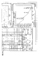
- FIGS. 6 , 7 , 8 , 9 , and 10 illustrate an example of one of the ‘one or more time or depth data displays’ of FIG. 2 which is generated by the computer system of FIGS. 1 and 2 when the Time Synchronization and Display software of FIG. 2 is executed by the computer system processor of FIG. 2 , FIG. 9 illustrating another feature associated with the ‘one or more time or depth data displays’ of FIG.
- a ‘play’ feature including a ‘play’ feature, a ‘pause’ feature, a ‘stop’ feature, a ‘fast reverse’ feature, a ‘fast forward’ feature, and a speed controller feature (located above the play and stop buttons) allowing a user to choose a playback speed when a plan feature is activated thereby allowing the user to play data at a multitude of speeds, such as two-times, three-times, . . . , ten-times, etc.;
- FIG. 11 illustrates a time line which is visible on the lower right portion of the display of FIG. 6 , the time line being usable and selectable by a user to select a particular period of time;
- FIG. 12 illustrates a depth data display, located adjacent a drill bit associated with a scaled image of a Bottom Hole Assembly (BHA), having display characteristics that are changed to correspond to a particular period of time when a user uses the time line of FIG. 11 to select the particular period of time.
- BHA Bottom Hole Assembly
- This specification discloses a method (and associated system and program storage device) for synchronizing various graphical views of data with a single point in time.
- real time measurement data such as drilling measurement data
- a multitude of such measurement data are being updated and displayed on the computer system display screen in real time.
- the measurement data may be viewed in different ways.
- the measurement data can be viewed in the form of a crossplot, or a pie chart, or a bar chart.
- the measurement data can be viewed, on the computer system display screen, in the form of ‘time based data’ or ‘depth based data’.
- This specification discloses a method (and associated system and program storage device) adapted for synchronizing all the received ‘real-time measurement data’ (and/or ‘historical data’) with respect to ‘one given selected point in time’.
- all the displays appearing on the computer system display screen are illustrating or displaying the same exact piece of measurement data and/or the same exact range of measurement data which was received at the ‘one given selected point in time’.
- a depth log is synchronized with, or correlated with, the time log at that ‘one given point in time’.
- the crossplots and pie charts and bar charts are also synchronized with the time log at that ‘one given point in time’.
- a drill bit is being moved up and down in a borehole during that period of time.
- a shorter ‘depth log’ e.g., 10,000 feet
- time log e.g., three days worth of time log data.
- BHA Bottom Hole Assembly
- this specification discloses a ‘Time Synchronization and Display software’ that will allow a user to move a ‘time log’ relative to a ‘time line’; and, when the user moves the ‘time log’ relative to the ‘time line’, a ‘positional log’ (for example, a ‘depth log’) is also moving relative to ‘one fixed point on an object of interest’ [e.g., relative to the ‘drill bit on a Bottom Hole Assembly (BHA) of a borehole tool’] in ‘synchronization’ with the movement of the ‘time log’ relative to the ‘time line’.
- a ‘positional log’ for example, a ‘depth log’
- BHA Bottom Hole Assembly
- the user can determine the exact ‘position’ (e.g., the depth) in the borehole where the ‘one fixed point on the object of interest’ (e.g., the drill bit on the BHA of the borehole tool) was located at any previous or current point in time.
- the exact ‘position’ e.g., the depth
- the ‘one fixed point on the object of interest’ e.g., the drill bit on the BHA of the borehole tool
- the user can select a ‘specific time’ by moving a ‘time log’ relative to a ‘time line’ and, responsive to that selection of the ‘specific time’, the user can then easily determine a position (e.g., a depth) on a ‘positional log’ (e.g., a ‘depth log’) where the ‘one fixed point on the object of interest’ (e.g., the drill bit on the BHA of the borehole tool) was located in the borehole at that ‘specific time’ because the ‘positional log’ (e.g., the ‘depth log’) is moving relative to the ‘object of interest’ [e.g., the Bottom Hole Assembly (BHA) of the borehole tool] in ‘synchronization’ with the movement of the ‘time log’ relative to the ‘time line’.
- a position e.g., a depth
- the ‘one fixed point on the object of interest’ e.g., the drill bit on the BHA of the borehole tool
- the position on the ‘positional log’ (e.g., the depth on the ‘depth log’) can be easily determined because, as the user is scrolling the ‘time log’ relative to the ‘time line’, the ‘positional log’ (e.g., the ‘depth log’) is also scrolling relative to the ‘one fixed point on the object of interest’ (e.g., relative to the drill bit on the BHA) in synchronization with the scrolling of the ‘time log’ relative to the ‘time line’.
- the other displays including the crossplots and the pie charts and the bar charts, will also be changed in synchronization with the scrolling of the ‘time log’ relative to the ‘time line’.
- a corresponding ‘positional log’ e.g., a ‘depth log’
- the ‘object of interest’ e.g., adjacent to the BHA of the borehole tool
- the ‘positional log’ e.g., the ‘depth log’
- the crossplots and the pie charts and the bar charts will also be adjusted in synchronization with the ‘time log’.
- the user will always be able to determine the position (e.g., the depth) on a ‘positional log’ (e.g., on a ‘depth log’) of the ‘object of interest’ (e.g., the Bottom Hole Assembly or BHA) in a borehole because the scrolling of the ‘positional log’ (e.g., the ‘depth log’) is accomplished in synchronization with the scrolling of a ‘time log’ relative to a ‘time line’.
- position e.g., the depth
- a ‘positional log’ e.g., on a ‘depth log’
- the ‘object of interest’ e.g., the Bottom Hole Assembly or BHA
- the Time Synchronization and Display software disclosed in this specification will therefore perform the following functions when executed by the processor of a computer system: (1) Ability to display Bit position versus Hole Depth relative to a “Time Line”; (2) The BHA's bit will follow the “Time Line” bit depth when the time line is moved; (3) The BHA is drawn to scale along the depth log showing how its components relate to the depth data, and this includes the actual position and sizes of stabilizers and the actual position of sensors in Measurement While Drilling (MWD)/Logging While Drilling (LWD) tools; (4) Ability to focus an analysis on a specific time point or period without manually rescaling or resizing each plot; (5) Compute a time breakdown of rig states using a pie or bar chart in conjunction with rig states; (6) Plot time data with respect to an axis other than time while synchronized with the “Time Line”; (7) Plot Depth data with respect to an axis other than depth while synchronized with the Hole Depth at the “Time Line”
- the engineering models are updated in real-time with some measurement data received in real-time.
- the newly updated models are then compared to other real-time measurement data; for example, update the ‘tripping loads model’ with user-defined ‘friction factors’, then plot actual hookload values against the model in real-time.
- a typical computer system is illustrated.
- a computer system 10 receives a program storage device 12 (such as a CD-ROM) on which is stored a software hereinafter known as a ‘Time Synchronization and Display software’ 14 .
- the program storage device 12 is inserted into the computer system 10 and the ‘Time Synchronization and Display software’ 14 is stored into the memory of the computer system 10 .
- the computer system 10 receives the following types of input data: (1) a ‘real time data stream’ 16 , (2) ‘historical data’ 18 , and (3) ‘engineering modeled data’ 19 .
- the ‘real time data stream’ 16 may contain data that may be displayed in ‘logs’ on a display screen.
- ‘real time data stream’ 16 may, itself, become ‘historical data’ 18 .
- the term ‘log’ refers to an output signal which is recorded on a sheet or chart with respect to an (x, y) axis, where the x-axis is usually ‘depth in a borehole’ and the y-axis is usually a measured parameter, such as resistivity or permeability.
- the computer system 10 is adapted for executing the ‘Time Synchronization and Display software’ 14 while using the ‘real time data stream’ 16 and the ‘historical data’ 18 and the ‘engineering modeled data’ 19 , and, responsive thereto, the computer system 10 will record on a ‘display’ (or otherwise printout or record or display on some other ‘recorder or display device’) an ‘output’ which is comprised of ‘one or more time or depth data displays’.
- the computer system 10 includes a processor 10 a operatively connected to a system bus 20 , a memory or other program storage device 10 b operatively connected to the system bus 20 , and a recorder or display device 10 c operatively connected to the system bus 20 .
- the memory or other program storage device 10 b stores the Time Synchronization and Display software 14 which was previously loaded into the memory 10 b from the program storage device 12 of FIG. 1 .
- the Time Synchronization and Display software 14 is owned and operated by Schlumberger Technology Corporation of Houston, Tex.
- the computer system 10 receives ‘Input Data’ 16 and 18 , where the ‘Input Data’ 16 and 18 includes: (1) the ‘real time data stream’ 16 , (2) the ‘historical data’ 18 , and (3) the ‘engineering modeled data’ 19 .
- the processor 10 a will execute the Time Synchronization and Display software 14 , while simultaneously using the ‘real time data stream’ 16 and the ‘historical data’ 18 and the ‘engineering modeled data’ 19 ; and, responsive thereto, the recorder or display device 10 c will generate ‘Output Data’ 22 which is adapted to be recorded by or displayed on the recorder or display device 10 c .
- the ‘Output Data’ 22 includes ‘one or more time or depth data displays’ 22 .
- the computer system 10 may be a personal computer (PC), a workstation, or a mainframe.
- workstations include a Silicon Graphics Indigo 2 workstation or a Sun SPARC workstation or a Sun ULTRA workstation or a Sun BLADE workstation.
- the ‘application’ disclosed in this specification is a ‘windows-based application’ running on any IBM compatible PC.
- the memory or program storage device 10 b is a computer readable medium or a program storage device which is readable by a machine, such as the processor 10 a .
- the processor 10 a may be, for example, a microprocessor, a microcontroller, or a mainframe or workstation processor.
- the memory or program storage device 10 b which stores the Time Synchronization and Display software 14 , may be, for example, a hard disk, ROM, CD-ROM, DRAM, or other RAM, flash memory, magnetic storage, optical storage, registers, or other volatile and/or non-volatile memory.
- FIGS. 3 , 4 , and 5 a detailed construction of the Time Synchronization and Display Software 14 of FIGS. 1 and 2 is illustrated.
- the Time Synchronization and Display Software 14 includes a ‘Data Processor, Loader, Correlation, and Synchronization control’ 24 (hereinafter, the ‘Data Processor’ 24 ).
- the ‘Data Processor’ 24 will receive a ‘real time data stream’ 16 and ‘historical data’ 18 and ‘engineering modeled data’ 19 , and, responsive thereto, the ‘Data Processor, Loader, Correlation, and Synchronization control’ 24 will generate the ‘one or more time or depth data displays’ 22 .
- the ‘Data Processor’ 24 can receive the ‘real time data stream’ 16 and, responsive thereto, generate ‘one or more time or depth data displays’ 22 which will display the ‘real time data stream’; or the ‘Data Processor’ 24 can receive the ‘historical data’ 18 and the ‘engineering modeled data’, and, responsive thereto, generate the ‘one or more time or depth data displays’ 22 which will display the ‘historical data’ and the ‘engineering modeled data’.
- a detailed construction of the ‘Data Processor, Loader, Correlation, and Synchronization control’ 24 of FIG. 3 includes: (1) a ‘Time Data Processor’ 24 a , which will receive the ‘real time data stream’ 16 and the ‘historical data’ 18 and the ‘engineering modeled data’ 19 , and, responsive thereto, the ‘Time Data Processor 24 a will generate ‘time data’ 24 b , ‘depth data’ 24 c , and ‘BHA data’ 24 d ; and (2) a ‘Data Loader, Correlation, Synchronization control 24 e which will receive the ‘time data’ 24 b and the ‘depth data’ 24 c .
- the ‘depth data’ 24 c includes: a ‘plurality of depth data values’, and a ‘plurality of time data values’ which correspond, respectively, to the ‘plurality of depth data values’; as a result, there exists a time value for each depth data value.
- the ‘Data Loader, Correlation, Synchronization control’ 24 e will receive the ‘time data’ 24 b and the ‘depth data’ 24 c from the ‘Time Data Processor’ 24 a , and, responsive thereto, the ‘Data Loader, Correlation, Synchronization control’ 24 e will then load ‘a portion of a particular depth data range’ of the ‘depth data’ associated with a ‘bit depth’ into each individual graphical object depending on a ‘selected time’ on a ‘time log’ relative to a ‘time line’ that is selected by a user.
- the ‘depth based data’ is synchronized with the ‘time based data’ via the time based ‘bit depth’ data, they can be synchronized using any time based depth measurement (e.g., hole depth or formation depth, etc).
- the ‘Data Loader, Correlation, Synchronization control’ 24 e will determine the ‘portion of the particular depth data range’ that is associated with a ‘bit depth’ at a ‘particular point in time’ of the ‘time data’ 24 b and then the ‘Data Loader, Correlation, Synchronization control’ 24 e will send that ‘portion of the particular depth data range’ to each graphical object which includes the ‘one or more time or depth data displays’ 22 (recall that a ‘graphical object’ is a crossplot or a pie chart or a bar chart or a ‘time log’ or a ‘depth log’).
- the ‘data loader’ portion of the ‘Data Loader, Correlation, Synchronization control’ 24 e will receive the ‘time data’ and the ‘depth data’, and, responsive thereto, the ‘data loader’ will send a ‘portion of the particular depth data range’ associated with each ‘bit depth’ of each ‘particular point in time’ of the ‘time data’ to the ‘synchronization control’.
- the ‘synchronization control’ portion of the ‘Data Loader, Correlation, Synchronization Control’ 24 e will send only that ‘portion of the particular depth data range’ associated with a single ‘bit depth’ corresponding to a ‘selected point in time’ to each graphical object (for loading therein) depending upon the ‘selected point in time’ that was selected by the user.
- the ‘selected point in time’ is selected by a user by adjusting a ‘time log’ relative to a ‘time line’ until the ‘time line’ is displayed directly over the ‘selected point in time’ on the ‘time log’ (this function will be discussed in more detail later in this specification).
- the ‘synchronization control’ tells each graphical object: “you are looking at only that ‘portion of the particular depth data range’ which ranges from a first depth to a second depth, the ‘portion of the particular depth data range’ corresponding to the ‘bit depth’ at the ‘selected point in time’”.
- the BHA data 24 d (which represents the ‘BHA’ of a borehole tool being displayed on the ‘one or more time or depth data displays’) will be sent directly to the ‘one or more time or depth data displays’ 22 .
- the ‘one or more time or depth data displays’ 22 represent multiple ‘graphical objects’ or graphical views of the time and depth data.
- the ‘one or more time or depth data displays’ 22 can be a crossplot, a pie chart, a bar chart, a ‘depth log’ adjacent to the BHA of a borehole tool (originating from the BHA data 24 d ), and a ‘time log’ adjacent to a ‘time line’.
- the ‘Data Loader, Correlation, and Synchronization Control’ 24 e includes: (1) a ‘Time Range Focus Controller’ 24 e 1 which receives the Time Data 24 b , (2) a ‘Time Data Loader’ 24 e 2 which receives an output from the ‘Time Range Focus Controller’ 24 e 1 , (3) a ‘Time Line Synchronization Control’ 24 e 3 which receives an output from the ‘Time Range Focus Controller 24 e 1 ’, and (4) a ‘Time ⁇ Depth Correlation Control’ 24 e 6 which receives the ‘depth data’ 24 c and an output on line 24 e 5 from the ‘Time Line Synchronization Control’ 24 e 3 .
- the ‘depth data’ 24 c includes: a plurality of depth data values, and a plurality of time data values which correspond, respectively, to the plurality of depth data values; as a result, there exists a time value for each depth data value.
- the ‘one or more time or depth data displays’ 22 of FIG. 4 includes: (1) ‘one or more time data displays’ 22 a which receives an output from the ‘Time Data Loader’ 24 e 2 and the ‘Time Line Synchronization Control’ 24 e 3 , (2) ‘one or more depth data displays’ 22 b which receives an output from the ‘Time ⁇ Depth Correlation Control’ 24 e 6 , and (3) a BHA Schematic vs.
- the ‘Time Range Focus Controller’ 24 e 1 receives the time data 24 b and, responsive thereto, sends ‘time range data’ to the ‘Time Data Loader’ 24 e 2 which will then send the ‘time range data’ to the ‘one or more time data displays’ 22 a .
- the ‘time range data’ is comprised of a range of times extending from a ‘start time’ to an ‘end time’.
- the ‘Time line Synchronization Control’ 24 e 3 will receive the ‘time range data’ from the ‘Time Range Focus Controller’ 24 e 1 and, responsive thereto, the ‘Time Line Synchronization Control’ 24 e 3 will determine a ‘current time in the data’, where the ‘current time in the data’ will be a specific time which lies within the ‘time range data’. The ‘Time Line Synchronization Control’ 24 e 3 will then send the ‘current time in the data’ to the ‘one or more time data displays’ 22 a of FIG. 5 .
- the ‘one or more time data displays’ 22 a will be receiving: (1) the ‘time range data’ (comprised of a range of times from the ‘start time’ to the ‘end time’) from the ‘Time Data Loader’ 24 e 2 , and (2) the ‘current time in the data’ from the ‘Time Line Synchronization Control’ 24 e 3 .
- the ‘Time Line Synchronization Control’ 24 e 3 will be sending the ‘current time in the data’ along a line 24 e 5 to the ‘Time ⁇ Depth Correlation Control’ 24 e 6 . Recall that the ‘Time ⁇ Depth Correlation Control’ 24 e 6 is receiving the ‘depth data’ 24 c .
- the ‘Time ⁇ Depth Correlation Control’ 24 e 6 will be receiving both the ‘current time in the data’ (from line 24 e 5 ) and the ‘depth data’ 24 c .
- the ‘depth data’ 24 c includes: a ‘plurality of depth data values’, and a ‘plurality of time data values’ which correspond, respectively, to the ‘plurality of depth data values’; as a result, there exists a time data value for each depth data value.
- the ‘Time ⁇ Depth Correlation Control’ 24 e 6 will perform the following function: the ‘Time ⁇ Depth Correlation Control’ 24 e 6 will receive the ‘current time in the data’ from line 24 e 5 ; the ‘Time ⁇ Depth Correlation Control’ 24 e 6 will then locate, from among the ‘plurality of time data values’ of the ‘depth data’ 24 c , a ‘particular time data value’ which corresponds directly to the received ‘current time in the data’, and then the ‘Time ⁇ Depth Correlation Control’ 24 e 6 will generate a ‘particular depth data value’, from among the ‘plurality of depth data values’ of the ‘depth data’ 24 c , which corresponds directly to the ‘particular time data value’.
- the ‘Time ⁇ Depth Correlation Control’ 24 e 6 stores in two columns the following information: a ‘plurality of particular depth data’ is stored in a first column, and a ‘corresponding plurality of ranges of depth data from zero to the particular depth data’ is stored in a second column which correspond, respectively, to the ‘plurality of particular depth data’ in the first column.
- the ‘Time ⁇ Depth Correlation Control’ 24 e 6 will then attempt to locate a match between the incoming ‘particular depth data value’ and ‘one of the plurality of particular depth data’ stored in the first column, and, when a match is found, the ‘Time ⁇ Depth Correlation Control’ 24 e 6 will then locate ‘one of the ranges of depth data from zero depth to the particular depth data value’ in the second column which corresponds to the ‘one of the plurality of particular depth data value’ in the first column.
- the ‘Time ⁇ Depth Correlation Control’ 24 e 6 will then send the aforesaid ‘one of the ranges of depth data from zero depth to the particular depth data value’ to both the ‘one or more depth data displays’ 22 b and the ‘BHA Schematic vs. Hole Depth’ display 22 c .
- the ‘Time ⁇ Depth Correlation Control’ 24 e 6 will: (1) receive the ‘current time in the data’ from line 24 e 5 ; (2) locate, from among the ‘plurality of time data values’ of the ‘depth data’ 24 c , a ‘particular time data value’ which corresponds directly to the received ‘current time in the data’; (3) generate a ‘particular depth data value’, from among the ‘plurality of depth data values’ of the ‘depth data’ 24 c , which corresponds directly to the ‘particular time data value’; (4) determine a ‘range of depth data from zero depth to the particular depth data value’ which corresponds directly to the ‘particular depth data value’; and (5) send the ‘range of depth data from zero depth to the particular depth data value’ to the ‘one or more depth data displays’ 22 b and to the ‘BHA Schematic vs.
- Hole Depth’ display 22 c the ‘one or more time data displays’ 22 a will be receiving the ‘time range data’ (comprised of a range of times from the ‘start time’ to the ‘end time’) from the ‘Time Data Loader’ 24 e 2 , and the ‘current time in the data’ from the ‘Time Line Synchronization Control’ 24 e 3 ; (2) the ‘one or more depth data displays’ 22 b will be receiving the ‘range of depth data from zero depth to the particular depth data value’ from the ‘Time ⁇ Depth Correlation Control’ 24 e 6 ; and (3) the ‘BHA Schematic vs. Hole Depth’ display 22 c will be receiving both: the ‘range of depth data from zero depth to the particular depth data value’ from the ‘Time ⁇ Depth Correlation Control’ 24 e 6 , and the BHA data 24 d.
- time range data (comprised of a range of times from the ‘start time’ to the ‘end time’) from the ‘Time Data Loader’ 24
- FIG. 6 which includes FIGS. 7 , 8 , 9 , and 10
- FIG. 11 and FIG. 12 one example of the ‘one or more time or depth data displays’ 22 of FIGS. 2 through 5 is illustrated.
- a scaled image of an ‘object of interest’ namely, a scaled image of a Bottom Hole Assembly (BHA) is illustrated.
- BHA Bottom Hole Assembly
- FIG. 6 includes: (1) FIG. 7 representing the upper left hand corner of FIG. 6 , (2) FIG. 8 representing the upper right hand corner of FIG. 6 , (3) FIG. 9 representing the lower left hand corner of FIG. 6 , and (4) FIG. 10 representing the lower right hand corner of FIG. 6 .
- FIG. 11 illustrates, in greater detail, the time line 22 a 1 relative to the time log 22 a 2 .
- FIG. 12 illustrates, in greater detail, the depth log 22 b 1 relative to the drill bit 22 c 2 of the Bottom Hole Assembly (BHA) 22 c 1 .
- BHA Bottom Hole Assembly
- the ‘one or more time or depth data displays’ 22 includes the ‘one or more time data displays’ 22 a , the ‘one or more depth data displays’ 22 b , and the ‘BHA Schematic vs hole depth’ 22 c .
- the ‘one or more time data displays’ 22 a includes a ‘time line’ 22 a 1 which is displayed over and adjacent to a ‘time log’ 22 a 2 .
- the ‘time log’ 22 a 2 can be adjusted, by a user, relative to the ‘time line’ 22 a 1 ; this adjustment will locate a ‘current time in the data’ (see line 24 e 5 of FIG. 5 which sends the ‘current time in the data’ from control 24 e 3 to control 24 e 6 ).
- the ‘one or more depth data displays’ 22 b includes a ‘depth log’ 22 b 1 which displays the depth of the Bottom Hole Assembly (BHA) in the borehole, and, in particular, the depth of a ‘drill bit’ 22 c 2 associated with the BHA in the borehole.
- the ‘BHA Schematic vs Hole Depth’ display 22 c includes the Bottom Hole Assembly (BHA) 22 c 1 and the ‘drill bit’ 22 c 2 associated with the BHA 22 c 1 .
- the ‘drill bit’ 22 c 2 is positioned adjacent to the ‘depth log’ 22 b 1 .
- the ‘depth log’ 22 b 1 can scroll upwardly and downwardly adjacent to the ‘drill bit’ 22 c 2 .
- the depth of the ‘drill bit’ 22 c 2 in the borehole can easily be determined by noting the location or position of the ‘drill bit’ 22 c 2 adjacent to the ‘depth log’ 22 b 1 on the depth data display 22 b and 22 c shown in FIG.
- the ‘drill bit’ 22 c 2 is positioned adjacent to depth ‘26955’ on the ‘depth log’ 22 b 1 in FIG. 6 .
- other displays are illustrated, such as the pie chart 22 d , the crossplot 22 e , and the bar chart 22 f.
- FIG. 11 an enlarged view of the ‘time line’ 22 a 1 and the ‘time log’ 22 a 2 of FIG. 6 is illustrated.
- the user can adjust or move the ‘time log’ 22 a 2 relative to the ‘time line’ 22 a 1 .
- the ‘current time in the data’ can easily be determined by adjusting or moving the ‘time log’ 22 a 2 relative to the ‘time line’ 22 a 1 until the ‘time line’ 22 a 1 is positioned directly over the ‘current time in the data’ on the ‘time log’ 22 a 2 .
- FIG. 12 an enlarged view of the BHA 22 c 1 and the ‘drill bit’ 22 c 2 and the ‘depth log’ 22 b 1 of FIG. 6 is illustrated.
- the BHA 22 c 1 is positioned adjacent to the ‘depth log’ 22 b 1 and, as a result, as the ‘depth log’ 22 b 1 moves upwardly and downwardly in FIG. 12 .
- the depth of the ‘drill bit’ 22 c 2 in the borehole can easily be determined by noting its position in the display of FIG. 12 relative to the ‘depth log’ 22 b 1 .
- the ‘drill bit’ 22 c 2 of FIG. 12 is located near the depth ‘26955’ on the ‘depth log’ 22 b 1 and, as a result, the depth of the ‘drill bit’ 22 c 2 in the borehole is approximately ‘26955’ feet.
- the movement of the ‘time log’ 22 a 2 relative to the ‘time line’ 22 a 1 is synchronized with the movement of the ‘depth log’ 22 b 1 relative to the BHA 22 c 1 and its ‘drill bit’ 22 c 2 .
- the BHA 22 c 1 of FIG. 6 is often moved uphole and downhole a plurality of times.
- the BHA 22 c 1 can be downhole
- time ‘t 2 ’ the BHA 22 c 1 can be uphole.
- the BHA 22 c 1 can be uphole, and at time ‘t 2 ’, the BHA 22 c 1 can be downhole. It would be desirable to know the depth of the BHA 22 c 1 in the borehole at all previous and current points in time.
- the ‘synchronization feature’ Since the movement of the ‘time log’ 22 a 2 relative to the ‘time line’ 22 a 1 is synchronized with the movement of the ‘depth log’ 22 b 1 relative to the BHA 22 c 1 and its ‘drill bit’ 22 c 2 (hereinafter called, the ‘synchronization feature’), one can easily determine the depth of the BHA 22 c 1 in the borehole (and the depth of the drill bit 22 c 2 of the BHA 22 c 1 in the borehole) at all previous and current points in time. This ‘synchronization feature’ can be more easily understood with reference to the functional ‘operation’ set forth below in the following paragraphs.
- the ‘one or more time or depth data displays’ 22 includes a ‘play’ button 30 adapted for practicing a ‘play’ feature, a ‘pause’ button 32 adapted for practicing a ‘pause’ feature, a ‘stop’ button 34 adapted for practicing a ‘stop’ feature, a ‘fast reverse’ button 36 adapted for practicing a ‘fast reverse’ feature, and a ‘fast forward’ button 38 adapted for practicing a ‘fast forward’ feature.
- a ‘play’ button 30 adapted for practicing a ‘play’ feature
- a ‘pause’ button 32 adapted for practicing a ‘pause’ feature
- a ‘stop’ button 34 adapted for practicing a ‘stop’ feature
- a ‘fast reverse’ button 36 adapted for practicing a ‘fast reverse’ feature
- a ‘fast forward’ button 38 adapted for practicing a ‘fast forward’ feature.
- the ‘input data’ includes ‘historical data’ 18 as well as a ‘real time data stream’ 16 , when viewing the ‘historical data’ 18 on the ‘one or more time or depth data displays’ 22 , it would be desirable to have the capability to fast forward or fast reverse through the historical data 18 when displaying the ‘historical data’ 18 on the ‘one or more time or depth data displays’ 22 including: (1) the ‘depth log’ 22 b in conjunction with the ‘BHA Schematic’ 22 c , together in association with (2) the ‘time log’ 22 a 2 in conjunction with the ‘time line’ 22 a 1 .
- the user can ‘play’ through the ‘historical data’ 18 being displayed on the ‘one or more time or depth data displays’ 22 of FIG. 6 by pressing or clicking on the ‘play’ button 30 in FIG. 9 .
- the user can ‘pause’ the viewing of the ‘historical data’ 18 being displayed on the ‘one or more time or depth data displays’ 22 of FIG. 6 by clicking on the ‘pause’ button 32 .
- a speed controller feature 40 allows the user to choose the playback speed. By using the speed controller feature 40 in FIG. 9 , the user to play data at a multitude of speeds, such as ‘two-times the normal speed’, or ‘three-times the normal speed’, or ‘four-times the normal speed’.
- the above referenced ‘synchronization feature’ functions in the following manner.
- a user adjusts the location of the ‘time log’ 22 a 2 relative to the ‘time line’ 22 a 1 until the ‘time line’ 22 a 1 is positioned directly over a ‘desired current time in the data’ on the ‘time log’ 22 a 2 .
- the aforementioned adjustment (by the user) of the location of the ‘time log’ 22 a 2 relative to the ‘timeline’ 22 a 1 in FIG.
- the ‘depth log’ 22 b 1 is also moving, in synchronism, relative to the ‘drill bit’ 22 c 2 of the BHA 22 c 1 . Therefore, when the ‘time line’ 22 a 1 ′ is positioned directly over the ‘desired current time in the data’ (which is somewhere between 08:00 and 08:30 on the ‘time log’ 22 a 2 of FIG. 11 ) on the ‘time log’ 22 a 2 of FIG. 11 , the ‘depth log’ 22 b 1 of FIG. 12 has already moved relative to the ‘drill bit’ 22 c 2 (and in synchronization with the movement of the ‘time log’ 22 a 2 relative to the ‘time line’ 22 a 1 of FIG.
- the ‘drill bit’ 22 c 2 of FIG. 12 is located at depth ‘26955’ feet in the borehole.
- the ‘time log’ 22 a 2 of FIGS. 6 and 11 is moved or adjusted, by the user, relative to the ‘time line’ 22 a 1 until a ‘desired current time in the data’ is located (at which point, the ‘time line’ 22 a 1 is positioned directly over the ‘desired current time in the data’ on the ‘time log’ 22 a 2 of FIGS.
- the other displays 22 d , 22 e , and 22 f shown in FIG. 6 i.e, the pie chart 22 d , the crossplot 22 e , and the bar chart 22 f
- the other displays 22 d , 22 e , and 22 f shown in FIG. 6 will also be adjusted, in synchronization, with the movement or adjustment of the ‘time log’ 22 a 2 relative to the ‘time line’ 22 a 1 .
- the other displays 22 d , 22 e , and 22 f shown in FIG. 6 i.e, the pie chart 22 d , the crossplot 22 e , and the bar chart 22 f
- the ‘one more more depth data displays’ 22 b and the ‘BHA Schematic vs Hole Depth’ display 22 c and the ‘other displays’ 22 d , 22 e , and 22 f will be adjusted, in synchronization, with the adjustment of the ‘time log’ 22 a 2 relative to the ‘time line’ 22 a 1 associated with the ‘one or more time data displays’ 22 a of FIGS.
- a ‘particular point in time’ or a ‘desired current time in the data’ is identified by the ‘time line’ 22 a 2 when the ‘time line’ 22 a 2 is positioned over the ‘particular point in time’ or the ‘desired current time in the data’ on the ‘time log’ 22 a 2 of FIGS. 6 and 11 .
- FIGS. 1 and 2 assume that the ‘Time Synchronization and Display software’ 14 of FIG. 1 has been loaded into the computer system 10 and that the ‘real time data stream’ 16 and/or the ‘historical data’ 18 and/or the ‘engineering modeled data’ 19 is provided to the computer system 10 as ‘input data’.
- the processor 10 a can now execute the ‘Time Synchronization and Display software’ 14 which is stored in the memory or program storage device 10 b while using the ‘input data’ which comprises the ‘real time data stream’ 16 and/or the ‘historical data’ 18 and/or the ‘engineering modeled data’ 19 .
- the ‘data output’ 22 of FIG. 2 will be generated by the ‘recorder or display device’ 10 c , the ‘data output’ 22 being ‘one or more time or depth data displays’ 22 .
- the ‘one or more time or depth data displays’ 22 can be either displayed on the ‘Display’ of the computer system 10 of FIG. 1 , or the ‘one or more time or depth data displays’ 22 can be recorded by the ‘recorder or display device’ 10 c .
- the ‘one or more time or depth data displays’ 22 will display either: (1) ‘real time data’ which corresponds to the ‘real time data stream’ 16 , or (2) ‘historical data’ and the ‘engineering modeled data’ which corresponds to the ‘historical data’ 18 .
- the ‘real time data’ would comprise data that is currently being generated, in ‘real time’, by a measuring apparatus, where the measuring apparatus is generating the ‘real time data’ at the present time and not in some past or previous point in time (such as by a measuring apparatus disposed downhole in a borehole that is currently measuring borehole data or drilling data in ‘real time’ at the present time).
- the ‘historical data’ would comprise data that was generated at some previous or past point in time by a measuring apparatus (such as by the measuring apparatus disposed downhole that already previously measured borehole data or drilling data at some past or previous point in time).
- the ‘Data Processor, Loader, Correlation, Synchronization Control’ 24 (or ‘Data Processor’ 24 ) portion of the ‘Time Synchronization and Display software’ 14 of FIG. 2 will receive the ‘real time data stream’ 16 and the ‘historical data’ 18 and the ‘engineering modeled data’ 19 and, responsive thereto, the ‘Data Processor’ 24 will generate the ‘one or more time or depth data displays’ 22 .
- Time Data Processor 24 a includes a Time Data Processor 24 a and a Data Loader, Correlation, Synchronization Control 24 e , the ‘Time Data Processor’ 24 a portion of the ‘Data Processor’ 24 will receive the ‘real time data stream’ 16 and the ‘historical data’ 18 and the ‘engineering modeled data’ 19 and, responsive thereto, will generate the ‘time data’ 24 b , the ‘depth data’ 24 c , and the BHA data 24 d .
- the BHA data 24 d goes directly to the ‘one or more time or depth data displays’ 22 . However, in FIG.
- the ‘time data’ 24 b and the ‘depth data’ 24 c is provided as input data to the ‘Data Loader, Correlation, Synchronization Control’ 24 e .
- the ‘Data Loader, Correlation, Synchronization control’ 24 e will receive the ‘time data’ 24 b and the ‘depth data’ 24 c from the ‘Time Data Processor’ 24 a , and, responsive thereto, the ‘Data Loader, Correlation, Synchronization control’ 24 e will then load a ‘portion of a particular depth data range’ of the ‘depth data’ 22 b 1 associated with a single ‘bit depth’ into each individual graphical object, where the aforementioned ‘portion of a particular depth data range’ corresponds to a ‘bit depth’ and the ‘bit depth’ corresponds to a ‘selected time’ on a ‘time log’ 22 a 2 relative to a ‘time line’ 22 a 1 , the ‘selected time’ being selected by a user.
- the ‘portion of a particular depth data range’ will be a range of depth data starting with ‘zero depth’ and ending with the ‘bit depth’.
- the ‘Time Range Focus Controller’ 24 e 1 receives the time data 24 b and, responsive thereto, sends ‘time range data’ to the ‘Time Data Loader’ 24 e 2 which will then send the ‘time range data’ to the ‘one or more time data displays’ 22 a .
- the ‘Time line Synchronization Control’ 24 e 3 will receive the ‘time range data’ from the ‘Time Range Focus Controller’ 24 e 1 and, responsive thereto, the ‘Time Line Synchronization Control’ 24 e 3 will determine a ‘current time in the data’, where the ‘current time in the data’ will be a specific time which lies within the ‘time range data’. The ‘Time Line Synchronization Control’ 24 e 3 will then send the ‘current time in the data’ to the ‘one or more time data displays’ 22 a of FIG. 5 .
- the ‘one or more time data displays’ 22 a will be receiving: (1) the ‘time range data’ (comprised of a range of times from the ‘start time’ to the ‘end time’) from the ‘Time Data Loader’ 24 e 2 , and (2) the ‘current time in the data’ from the ‘Time Line Synchronization Control’ 24 e 3 .
- the ‘Time Line Synchronization Control’ 24 e 3 will be sending the ‘current time in the data’ along a line 24 e 5 to the ‘Time ⁇ Depth Correlation Control’ 24 e 6 .
- the ‘Time ⁇ Depth Correlation Control’ 24 e 6 will: (1) receive the ‘current time in the data’ from line 24 e 5 ; (2) locate, from among the ‘plurality of time data values’ of the ‘depth data’ 24 c , a ‘particular time data value’ which corresponds directly to the received ‘current time in the data’; (3) generate a ‘particular depth data value’, from among the ‘plurality of depth data values’ of the ‘depth data’ 24 c , which corresponds directly to the ‘particular time data value’; (4) determine a ‘range of depth data from zero depth to the particular depth data value’ which corresponds directly to the ‘particular depth data value’; and (5) send the ‘range of depth data from zero depth to the particular depth data value’ to the ‘one or more depth data displays’ 22 b and to the ‘BHA Schematic vs.
- Hole Depth’ display 22 c the ‘one or more time data displays’ 22 a will be receiving the ‘time range data’ (comprised of a range of times from the ‘start time’ to the ‘end time’) from the ‘Time Data Loader’ 24 e 2 , and the ‘current time in the data’ from the ‘Time Line Synchronization Control’ 24 e 3 ; the ‘one or more depth data displays’ 22 b will be receiving the ‘range of depth data from zero depth to the particular depth data value’ from the ‘Time ⁇ Depth Correlation Control’ 24 e 6 ; and the ‘BHA Schematic vs. Hole Depth’ display 22 c will be receiving both: the ‘range of depth data from zero depth to the particular depth data value’ from the ‘Time ⁇ Depth Correlation Control’ 24 e 6 , and the BHA data 24 d.
- time range data (comprised of a range of times from the ‘start time’ to the ‘end time’) from the ‘Time Data Loader’ 24 e 2
- FIG. 11 assume that a user adjusts the location of the ‘time log’ 22 a 2 relative to the ‘time line’ 22 a 1 until the ‘time line’ 22 a 1 is positioned directly over a ‘desired current time in the data’ on the ‘time log’ 22 a 2 .
- the ‘depth log’ 22 b 1 is also moving, in synchronism, relative to the ‘drill bit’ 22 c 2 of the BHA 22 c 1 .
- the ‘depth log’ 22 b 1 of FIG. 12 has already moved relative to the ‘drill bit’ 22 c 2 (and in synchronization with the movement of the ‘time log’ 22 a 2 relative to the ‘time line’ 22 a 1 of FIG. 11 ) until the ‘drill bit’ 22 c 2 is positioned adjacent the depth ‘26955’ on the ‘depth log’ 22 b 1 .
- the ‘drill bit’ 22 c 2 of FIG. 12 is located at depth ‘26955’ feet in the borehole.
- the ‘time log’ 22 a 2 of FIGS. 11 and 12 is moved or adjusted, by the user, relative to the ‘time line’ 22 a 1 until a ‘desired current time in the data’ is located (at which point, the ‘time line’ 22 a 1 is positioned directly over the ‘desired current time in the data’ on the ‘time log’ 22 a 2 of FIGS. 11 and 12 ), the other displays 22 d , 22 e , and 22 f shown in FIG.
- the user can: ‘play’ the viewing of the ‘historical data’ 18 on the ‘one or more time or depth data displays’ 22 by clicking on the ‘play’ button 30 , or (2) ‘pause’ the viewing of the ‘historical data’ 18 by clicking on the ‘pause’ button 32 , or (3) ‘stop’ the viewing of the ‘historical data’ 18 by clicking on the ‘stop’ button 34 , or (4) ‘fast reverse’ the viewing of the ‘historical data’ 18 by clicking on the ‘fast reverse’ feature 36 , or (5) ‘fast forward’ the viewing of the ‘historical data’ 18 by clicking on the ‘fast forward’ button 38 , or (6) use the ‘speed controller feature’ 40 to vary the playback speed, such as to play back at ‘two-times the normal speed’ or ‘three-times the normal speed’, etc.
- the invention disclosed in this specification is applicable to any process where the position of an ‘object of interest’ varies along a fixed path in space and time. For example, it could equally be applicable to a train on a railway line.
- the ‘object of interest’ e.g., the BHA 22 c 1 of FIG. 12
- goes back and forth along the same path e.g., a wellbore
- the BHA 22 c 1 goes back and forth along the same wellbore path a multiple number of times.
- the BHA 22 c 1 and the depth image 22 b 1 can be rescaled and scrolled such that the depth log 22 b 1 can be viewed in detail with respect to ‘other points of interest’ on the BHA 22 c 1 , other than the drill bit 22 c 2 , such as with respect to the stabilizers.
- the time/depth correlation is dependent on the fact that the position of ‘one fixed point on the object of interest’ is known in the time domain.
- the ‘one fixed point on the object of interest’ is the drill bit 22 c 2 on a BHA 22 c 1 .
- the ‘one fixed point on the object of interest’ could include ‘other fixed points’ on ‘an object of interest’; for example, the ‘other fixed point’ could be a stabilizer; and, in that case, the ‘stabilizer depth’ would be monitored instead of the ‘drill bit depth’.
- the ‘other fixed point’ could be a stabilizer; and, in that case, the ‘stabilizer depth’ would be monitored instead of the ‘drill bit depth’.
- FIG. 6 in addition to ‘historical data’ 18 , we could also be comparing ‘depth logs’ to ‘planned depth logs’.
Abstract
Description
Claims (16)
Priority Applications (1)
| Application Number | Priority Date | Filing Date | Title |
|---|---|---|---|
| US11/112,278 US7526930B2 (en) | 2005-04-22 | 2005-04-22 | Method system and program storage device for synchronizing displays relative to a point in time |
Applications Claiming Priority (1)
| Application Number | Priority Date | Filing Date | Title |
|---|---|---|---|
| US11/112,278 US7526930B2 (en) | 2005-04-22 | 2005-04-22 | Method system and program storage device for synchronizing displays relative to a point in time |
Publications (2)
| Publication Number | Publication Date |
|---|---|
| US20060239118A1 US20060239118A1 (en) | 2006-10-26 |
| US7526930B2 true US7526930B2 (en) | 2009-05-05 |
Family
ID=37186711
Family Applications (1)
| Application Number | Title | Priority Date | Filing Date |
|---|---|---|---|
| US11/112,278 Active 2025-12-02 US7526930B2 (en) | 2005-04-22 | 2005-04-22 | Method system and program storage device for synchronizing displays relative to a point in time |
Country Status (1)
| Country | Link |
|---|---|
| US (1) | US7526930B2 (en) |
Cited By (4)
| Publication number | Priority date | Publication date | Assignee | Title |
|---|---|---|---|---|
| US20150324500A1 (en) * | 2012-12-14 | 2015-11-12 | Schlumberger Technology Corporation | Drilling Data Visualization Method |
| US9528334B2 (en) | 2009-07-30 | 2016-12-27 | Halliburton Energy Services, Inc. | Well drilling methods with automated response to event detection |
| US9567843B2 (en) | 2009-07-30 | 2017-02-14 | Halliburton Energy Services, Inc. | Well drilling methods with event detection |
| CN108885556A (en) * | 2016-03-24 | 2018-11-23 | 微软技术许可有限责任公司 | Control numeral input |
Families Citing this family (16)
| Publication number | Priority date | Publication date | Assignee | Title |
|---|---|---|---|---|
| US7526930B2 (en) | 2005-04-22 | 2009-05-05 | Schlumberger Technology Corporation | Method system and program storage device for synchronizing displays relative to a point in time |
| WO2007130039A1 (en) * | 2006-05-04 | 2007-11-15 | Schlumberger Technology Corporation | Method system and program storage device for synchronizing displays relative to a point in time |
| US8160395B2 (en) * | 2006-11-22 | 2012-04-17 | General Electric Company | Method and apparatus for synchronizing corresponding landmarks among a plurality of images |
| US8705318B2 (en) | 2008-03-10 | 2014-04-22 | Schlumberger Technology Corporation | Data aggregation for drilling operations |
| US20090234623A1 (en) * | 2008-03-12 | 2009-09-17 | Schlumberger Technology Corporation | Validating field data |
| US8857510B2 (en) * | 2009-04-03 | 2014-10-14 | Schlumberger Technology Corporation | System and method for determining movement of a drilling component in a wellbore |
| US8554483B2 (en) | 2010-01-11 | 2013-10-08 | Schlumberger Technology Corporation | Methods and apparatus to process measurements associated with drilling operations |
| US8838390B1 (en) * | 2011-02-17 | 2014-09-16 | Selman and Associates, Ltd. | System for gas detection, well data collection, and real time streaming of well logging data |
| US8775088B1 (en) * | 2011-02-17 | 2014-07-08 | Selman and Associates, Ltd. | Method for acquiring and displaying in near real time gas analysis, well data collection, and other well logging data |
| US8775087B1 (en) * | 2011-02-17 | 2014-07-08 | Selman and Associates, Ltd. | System for acquiring and displaying in near real time gas analysis, well data collection, and other well logging data |
| US20130249917A1 (en) * | 2012-03-26 | 2013-09-26 | Microsoft Corporation | Profile data visualization |
| US9946445B2 (en) * | 2012-08-10 | 2018-04-17 | Landmark Graphics Corporation | Navigating to failures in drilling system displays |
| US9957781B2 (en) | 2014-03-31 | 2018-05-01 | Hitachi, Ltd. | Oil and gas rig data aggregation and modeling system |
| WO2015152880A1 (en) * | 2014-03-31 | 2015-10-08 | Hitachi, Ltd | Oil and gas rig data aggregation and modeling system |
| EP3294985A4 (en) * | 2015-05-13 | 2019-01-16 | Halliburton Energy Services, Inc. | Timeline visualization of events for monitoring well site drilling operations |
| DE102018104332A1 (en) * | 2018-02-26 | 2019-08-29 | Liebherr-Werk Nenzing Gmbh | Attachment for drilling and / or foundation work |
Citations (29)
| Publication number | Priority date | Publication date | Assignee | Title |
|---|---|---|---|---|
| US4422165A (en) * | 1981-02-11 | 1983-12-20 | Mobil Oil Corporation | Maximum likelihood estimation of the ratio of the velocities of compressional and shear waves |
| US4809236A (en) * | 1986-10-15 | 1989-02-28 | Schlumberger Technology Corporation | Method and apparatus for determining the magnitude of components of measurements made from inside a borehole |
| US5278805A (en) * | 1992-10-26 | 1994-01-11 | Schlumberger Technology Corporation | Sonic well logging methods and apparatus utilizing dispersive wave processing |
| US5361379A (en) * | 1991-10-03 | 1994-11-01 | Rockwell International Corporation | Soft-decision classifier |
| US5442741A (en) * | 1991-11-13 | 1995-08-15 | Hewlett-Packard Company | Method for displaying pie chart information on a computer screen |
| US5544267A (en) * | 1993-11-24 | 1996-08-06 | Xerox Corporation | Using a category to analyze an image showing a graphical representation |
| US5594706A (en) * | 1993-12-20 | 1997-01-14 | Schlumberger Technology Corporation | Downhole processing of sonic waveform information |
| US5917482A (en) * | 1996-03-18 | 1999-06-29 | Philips Electronics N.A. Corporation | Data synchronizing system for multiple memory array processing field organized data |
| US6152246A (en) | 1998-12-02 | 2000-11-28 | Noble Drilling Services, Inc. | Method of and system for monitoring drilling parameters |
| US6211873B1 (en) * | 1997-12-03 | 2001-04-03 | Todd Moyer | Method and apparatus for graphically representing information stored in electronic media |
| US20020069218A1 (en) * | 2000-07-24 | 2002-06-06 | Sanghoon Sull | System and method for indexing, searching, identifying, and editing portions of electronic multimedia files |
| US20020133774A1 (en) * | 2000-11-21 | 2002-09-19 | Ando Electric Co.,Ltd. | Semiconductor test apparatus |
| US6549879B1 (en) * | 1999-09-21 | 2003-04-15 | Mobil Oil Corporation | Determining optimal well locations from a 3D reservoir model |
| US20030126136A1 (en) * | 2001-06-22 | 2003-07-03 | Nosa Omoigui | System and method for knowledge retrieval, management, delivery and presentation |
| US20030210899A1 (en) * | 2002-05-08 | 2003-11-13 | Kabushiki Kaisha Toshiba | Replace processing method and replace processing apparatus |
| US6654688B1 (en) * | 1999-04-01 | 2003-11-25 | Schlumberger Technology Corporation | Processing sonic waveform measurements |
| US20040010373A1 (en) * | 2002-07-11 | 2004-01-15 | Smits Jan W. | Intelligent diagnosis of environmental influence on well logs with model-based inversion |
| US6704656B1 (en) * | 2002-10-18 | 2004-03-09 | Schlumberger Technology Corporation | Method, apparatus and computer program product to allow automatic product composition |
| US20040051650A1 (en) * | 2002-09-16 | 2004-03-18 | Bryan Gonsoulin | Two way data communication with a well logging tool using a TCP-IP system |
| US20040064258A1 (en) * | 2002-09-30 | 2004-04-01 | Ireland Peter J. | Method, apparatus and computer program product for creating ream section from memory data based on real-time reaming |
| US6760665B1 (en) * | 2003-05-21 | 2004-07-06 | Schlumberger Technology Corporation | Data central for manipulation and adjustment of down hole and surface well site recordings |
| US20040210392A1 (en) * | 2003-04-11 | 2004-10-21 | Schlumberger Technology Corporation | [system and method for visualizing multi-scale data alongside a 3d trajectory] |
| US20050189483A1 (en) * | 2004-02-26 | 2005-09-01 | Baker Hughes Incorporated | Azimuthal binning of density and porosity data |
| US20050199425A1 (en) * | 2003-12-03 | 2005-09-15 | Baker Hughes Incorporated | Magnetometers for measurement-while-drilling applications |
| US20050228590A1 (en) * | 2001-12-13 | 2005-10-13 | Jeffryes Benjamin P | Method for correlating well logs |
| US20050227625A1 (en) * | 2004-03-25 | 2005-10-13 | Diener Neil R | User interface and time-shifted presentation of data in a system that monitors activity in a shared radio frequency band |
| US20050234647A1 (en) * | 2004-04-19 | 2005-10-20 | Pathfinder Energy Services, Inc. | Enhanced measurement of azimuthal dependence of subterranean parameters |
| US20060080432A1 (en) * | 2004-09-03 | 2006-04-13 | Spataro Jared M | Systems and methods for collaboration |
| US20060239118A1 (en) | 2005-04-22 | 2006-10-26 | Schlumberger Technology Corporation | Method system and program storage device for synchronizing displays relative to a point in time |
-
2005
- 2005-04-22 US US11/112,278 patent/US7526930B2/en active Active
Patent Citations (29)
| Publication number | Priority date | Publication date | Assignee | Title |
|---|---|---|---|---|
| US4422165A (en) * | 1981-02-11 | 1983-12-20 | Mobil Oil Corporation | Maximum likelihood estimation of the ratio of the velocities of compressional and shear waves |
| US4809236A (en) * | 1986-10-15 | 1989-02-28 | Schlumberger Technology Corporation | Method and apparatus for determining the magnitude of components of measurements made from inside a borehole |
| US5361379A (en) * | 1991-10-03 | 1994-11-01 | Rockwell International Corporation | Soft-decision classifier |
| US5442741A (en) * | 1991-11-13 | 1995-08-15 | Hewlett-Packard Company | Method for displaying pie chart information on a computer screen |
| US5278805A (en) * | 1992-10-26 | 1994-01-11 | Schlumberger Technology Corporation | Sonic well logging methods and apparatus utilizing dispersive wave processing |
| US5544267A (en) * | 1993-11-24 | 1996-08-06 | Xerox Corporation | Using a category to analyze an image showing a graphical representation |
| US5594706A (en) * | 1993-12-20 | 1997-01-14 | Schlumberger Technology Corporation | Downhole processing of sonic waveform information |
| US5917482A (en) * | 1996-03-18 | 1999-06-29 | Philips Electronics N.A. Corporation | Data synchronizing system for multiple memory array processing field organized data |
| US6211873B1 (en) * | 1997-12-03 | 2001-04-03 | Todd Moyer | Method and apparatus for graphically representing information stored in electronic media |
| US6152246A (en) | 1998-12-02 | 2000-11-28 | Noble Drilling Services, Inc. | Method of and system for monitoring drilling parameters |
| US6654688B1 (en) * | 1999-04-01 | 2003-11-25 | Schlumberger Technology Corporation | Processing sonic waveform measurements |
| US6549879B1 (en) * | 1999-09-21 | 2003-04-15 | Mobil Oil Corporation | Determining optimal well locations from a 3D reservoir model |
| US20020069218A1 (en) * | 2000-07-24 | 2002-06-06 | Sanghoon Sull | System and method for indexing, searching, identifying, and editing portions of electronic multimedia files |
| US20020133774A1 (en) * | 2000-11-21 | 2002-09-19 | Ando Electric Co.,Ltd. | Semiconductor test apparatus |
| US20030126136A1 (en) * | 2001-06-22 | 2003-07-03 | Nosa Omoigui | System and method for knowledge retrieval, management, delivery and presentation |
| US20050228590A1 (en) * | 2001-12-13 | 2005-10-13 | Jeffryes Benjamin P | Method for correlating well logs |
| US20030210899A1 (en) * | 2002-05-08 | 2003-11-13 | Kabushiki Kaisha Toshiba | Replace processing method and replace processing apparatus |
| US20040010373A1 (en) * | 2002-07-11 | 2004-01-15 | Smits Jan W. | Intelligent diagnosis of environmental influence on well logs with model-based inversion |
| US20040051650A1 (en) * | 2002-09-16 | 2004-03-18 | Bryan Gonsoulin | Two way data communication with a well logging tool using a TCP-IP system |
| US20040064258A1 (en) * | 2002-09-30 | 2004-04-01 | Ireland Peter J. | Method, apparatus and computer program product for creating ream section from memory data based on real-time reaming |
| US6704656B1 (en) * | 2002-10-18 | 2004-03-09 | Schlumberger Technology Corporation | Method, apparatus and computer program product to allow automatic product composition |
| US20040210392A1 (en) * | 2003-04-11 | 2004-10-21 | Schlumberger Technology Corporation | [system and method for visualizing multi-scale data alongside a 3d trajectory] |
| US6760665B1 (en) * | 2003-05-21 | 2004-07-06 | Schlumberger Technology Corporation | Data central for manipulation and adjustment of down hole and surface well site recordings |
| US20050199425A1 (en) * | 2003-12-03 | 2005-09-15 | Baker Hughes Incorporated | Magnetometers for measurement-while-drilling applications |
| US20050189483A1 (en) * | 2004-02-26 | 2005-09-01 | Baker Hughes Incorporated | Azimuthal binning of density and porosity data |
| US20050227625A1 (en) * | 2004-03-25 | 2005-10-13 | Diener Neil R | User interface and time-shifted presentation of data in a system that monitors activity in a shared radio frequency band |
| US20050234647A1 (en) * | 2004-04-19 | 2005-10-20 | Pathfinder Energy Services, Inc. | Enhanced measurement of azimuthal dependence of subterranean parameters |
| US20060080432A1 (en) * | 2004-09-03 | 2006-04-13 | Spataro Jared M | Systems and methods for collaboration |
| US20060239118A1 (en) | 2005-04-22 | 2006-10-26 | Schlumberger Technology Corporation | Method system and program storage device for synchronizing displays relative to a point in time |
Non-Patent Citations (3)
| Title |
|---|
| Lassoued, Chaden, "Remote support leverages assets," E&P, Mar. 2006, Hart Energy Publishing, Houston, Texas, USA. |
| Schlumberger, "PerformView-Real-time drilling and visualization software," Dec. 2005. |
| SPE International-Java Indonesia Section, "SPE News, A Members Magazine," Apr. 2006, pp. 1-24, Jakarta. |
Cited By (5)
| Publication number | Priority date | Publication date | Assignee | Title |
|---|---|---|---|---|
| US9528334B2 (en) | 2009-07-30 | 2016-12-27 | Halliburton Energy Services, Inc. | Well drilling methods with automated response to event detection |
| US9567843B2 (en) | 2009-07-30 | 2017-02-14 | Halliburton Energy Services, Inc. | Well drilling methods with event detection |
| US20150324500A1 (en) * | 2012-12-14 | 2015-11-12 | Schlumberger Technology Corporation | Drilling Data Visualization Method |
| US10430530B2 (en) * | 2012-12-14 | 2019-10-01 | Schlumberger Technology Corporation | Drilling data visualization method |
| CN108885556A (en) * | 2016-03-24 | 2018-11-23 | 微软技术许可有限责任公司 | Control numeral input |
Also Published As
| Publication number | Publication date |
|---|---|
| US20060239118A1 (en) | 2006-10-26 |
Similar Documents
| Publication | Publication Date | Title |
|---|---|---|
| US7526930B2 (en) | Method system and program storage device for synchronizing displays relative to a point in time | |
| US6760665B1 (en) | Data central for manipulation and adjustment of down hole and surface well site recordings | |
| US20210157477A1 (en) | Interactive user interfaces for location-based data analysis | |
| AU2011382642B2 (en) | Geological monitoring console | |
| US7671867B2 (en) | Method for locating underground deposits of hydrocarbon including a method for highlighting an object in a three dimensional scene | |
| CN102893283B (en) | For the system and method for horizontal well correlation and geosteering | |
| US6772066B2 (en) | Interactive rock stability display | |
| US9013573B2 (en) | Knowledge capture and sharing for exploration and production tool sessions | |
| US10049474B2 (en) | Well activity bar charts | |
| US6704656B1 (en) | Method, apparatus and computer program product to allow automatic product composition | |
| Akimov et al. | Evolution of Drilling Dynamics Measurement Systems | |
| WO2018018661A1 (en) | Display method of interactive stability display system for rock slope | |
| CA2416216C (en) | Well-log presentation, software and method thereof | |
| EP2914808B1 (en) | Method and system for performing friction factor calibration | |
| AU2017383097A1 (en) | Monitoring, auditing and/or determining depth of or in a borehole | |
| US20040064258A1 (en) | Method, apparatus and computer program product for creating ream section from memory data based on real-time reaming | |
| WO2007130039A1 (en) | Method system and program storage device for synchronizing displays relative to a point in time | |
| Lesso Jr et al. | Continuous direction and inclination measurements revolutionize real-time directional drilling decision-making | |
| Degrange et al. | Sonic while drilling: multipole acoustic tools for multiple answers | |
| WO2018018660A1 (en) | Interactive stability display system for estimation of rock slope | |
| Underhill et al. | Demonstrations of real-time borehole seismic from an LWD tool | |
| US20040189637A1 (en) | System and method for displaying well log graphics at multiple levels of resolution | |
| Jogi et al. | Visualization of BHA dynamics improves understanding of downhole drilling conditions, speeds up learning curve | |
| Kyllingstad et al. | Factors limiting the quantitative use of mud-logging data | |
| Tollefsen et al. | Logging while drilling measurements: from correlation to evaluation |
Legal Events
| Date | Code | Title | Description |
|---|---|---|---|
| AS | Assignment |
Owner name: SCHLUMBERGER TECHNOLOGY CORPORATION, TEXAS Free format text: ASSIGNMENT OF ASSIGNORS INTEREST;ASSIGNOR:ESSAWI, AMR KHAIRY MOHAMED AHMED;REEL/FRAME:016501/0153 Effective date: 20050401 Owner name: SCHLUMBERGER TECHNOLOGY CORPORATION, TEXAS Free format text: ASSIGNMENT OF ASSIGNORS INTEREST;ASSIGNOR:JAMES, JOHN;REEL/FRAME:016501/0140 Effective date: 20050328 Owner name: SCHLUMBERGER TECHNOLOGY CORPORATION, TEXAS Free format text: ASSIGNMENT OF ASSIGNORS INTEREST;ASSIGNOR:AHORUKOMEYE, MBAGA LOUIS;REEL/FRAME:016501/0201 Effective date: 20050324 Owner name: SCHLUMBERGER TECHNOLOGY CORPORATION, TEXAS Free format text: ASSIGNMENT OF ASSIGNORS INTEREST;ASSIGNOR:CHAPMAN, CLINTON;REEL/FRAME:016501/0157 Effective date: 20050329 Owner name: SCHLUMBERGER TECHNOLOGY CORPROATION, TEXAS Free format text: ASSIGNMENT OF ASSIGNORS INTEREST;ASSIGNOR:BELASKIE, JIM;REEL/FRAME:016501/0126 Effective date: 20050404 Owner name: SCHLUMBERGER TECHNOLOGY CORPORATION, TEXAS Free format text: ASSIGNMENT OF ASSIGNORS INTEREST;ASSIGNOR:GUIDRY, JONATHAN;REEL/FRAME:016501/0105 Effective date: 20050324 Owner name: SCHLUMBERGER TECHNOLOGY CORPORATION, TEXAS Free format text: ASSIGNMENT OF ASSIGNORS INTEREST;ASSIGNOR:BRICOUT, VINCENT;REEL/FRAME:016501/0101 Effective date: 20050329 Owner name: SCHLUMBERGER TECHNOLOGY CORPORATION, TEXAS Free format text: ASSIGNMENT OF ASSIGNORS INTEREST;ASSIGNOR:MEEHAN, RICHARD;REEL/FRAME:016501/0165 Effective date: 20050329 Owner name: SCHLUMBERGER TECHNOLOGY CORPORATION, TEXAS Free format text: ASSIGNMENT OF ASSIGNORS INTEREST;ASSIGNOR:FANG, JOSEPH;REEL/FRAME:016501/0133 Effective date: 20050324 |
|
| STCF | Information on status: patent grant |
Free format text: PATENTED CASE |
|
| FPAY | Fee payment |
Year of fee payment: 4 |
|
| FPAY | Fee payment |
Year of fee payment: 8 |
|
| MAFP | Maintenance fee payment |
Free format text: PAYMENT OF MAINTENANCE FEE, 12TH YEAR, LARGE ENTITY (ORIGINAL EVENT CODE: M1553); ENTITY STATUS OF PATENT OWNER: LARGE ENTITY Year of fee payment: 12 |