US7351238B2 - Catheter having a reinforcing mandrel - Google Patents
Catheter having a reinforcing mandrel Download PDFInfo
- Publication number
- US7351238B2 US7351238B2 US10/692,365 US69236503A US7351238B2 US 7351238 B2 US7351238 B2 US 7351238B2 US 69236503 A US69236503 A US 69236503A US 7351238 B2 US7351238 B2 US 7351238B2
- Authority
- US
- United States
- Prior art keywords
- mandrel
- catheter
- tubular member
- lumen
- proximal
- Prior art date
- Legal status (The legal status is an assumption and is not a legal conclusion. Google has not performed a legal analysis and makes no representation as to the accuracy of the status listed.)
- Expired - Fee Related, expires
Links
Images


Classifications
-
- A—HUMAN NECESSITIES
- A61—MEDICAL OR VETERINARY SCIENCE; HYGIENE
- A61M—DEVICES FOR INTRODUCING MEDIA INTO, OR ONTO, THE BODY; DEVICES FOR TRANSDUCING BODY MEDIA OR FOR TAKING MEDIA FROM THE BODY; DEVICES FOR PRODUCING OR ENDING SLEEP OR STUPOR
- A61M25/00—Catheters; Hollow probes
- A61M25/0021—Catheters; Hollow probes characterised by the form of the tubing
- A61M25/0023—Catheters; Hollow probes characterised by the form of the tubing by the form of the lumen, e.g. cross-section, variable diameter
- A61M25/0026—Multi-lumen catheters with stationary elements
- A61M25/0029—Multi-lumen catheters with stationary elements characterized by features relating to least one lumen located at the middle part of the catheter, e.g. slots, flaps, valves, cuffs, apertures, notches, grooves or rapid exchange ports
-
- A—HUMAN NECESSITIES
- A61—MEDICAL OR VETERINARY SCIENCE; HYGIENE
- A61M—DEVICES FOR INTRODUCING MEDIA INTO, OR ONTO, THE BODY; DEVICES FOR TRANSDUCING BODY MEDIA OR FOR TAKING MEDIA FROM THE BODY; DEVICES FOR PRODUCING OR ENDING SLEEP OR STUPOR
- A61M25/00—Catheters; Hollow probes
- A61M25/0021—Catheters; Hollow probes characterised by the form of the tubing
- A61M25/0023—Catheters; Hollow probes characterised by the form of the tubing by the form of the lumen, e.g. cross-section, variable diameter
- A61M25/0026—Multi-lumen catheters with stationary elements
- A61M25/0032—Multi-lumen catheters with stationary elements characterized by at least one unconventionally shaped lumen, e.g. polygons, ellipsoids, wedges or shapes comprising concave and convex parts
-
- A—HUMAN NECESSITIES
- A61—MEDICAL OR VETERINARY SCIENCE; HYGIENE
- A61M—DEVICES FOR INTRODUCING MEDIA INTO, OR ONTO, THE BODY; DEVICES FOR TRANSDUCING BODY MEDIA OR FOR TAKING MEDIA FROM THE BODY; DEVICES FOR PRODUCING OR ENDING SLEEP OR STUPOR
- A61M25/00—Catheters; Hollow probes
- A61M2025/0004—Catheters; Hollow probes having two or more concentrically arranged tubes for forming a concentric catheter system
-
- A—HUMAN NECESSITIES
- A61—MEDICAL OR VETERINARY SCIENCE; HYGIENE
- A61M—DEVICES FOR INTRODUCING MEDIA INTO, OR ONTO, THE BODY; DEVICES FOR TRANSDUCING BODY MEDIA OR FOR TAKING MEDIA FROM THE BODY; DEVICES FOR PRODUCING OR ENDING SLEEP OR STUPOR
- A61M25/00—Catheters; Hollow probes
- A61M25/0043—Catheters; Hollow probes characterised by structural features
- A61M25/0054—Catheters; Hollow probes characterised by structural features with regions for increasing flexibility
Definitions
- This invention relates to the field of medical devices, and more particularly to a balloon catheter having a reinforcing mandrel.
- catheters designed for intravascular procedures have a number of desirable characteristics. Such catheters must be able to transmit force along the length of the catheter shaft to allow it to be pushed through the vasculature. However, the catheter shaft must also retain sufficient flexibility to allow it to track over a guidewire through the often tortuous vasculature. Additionally, the catheter also must be able to cross stenosed portions of the vascular anatomy.
- prior art designs have supplemented polymer catheter shafts with a stiffening wire or mandrel.
- Other prior art designs have addressed these handling and performance issues by using materials of different stiffness for the proximal and distal portions of the catheter, and employing a high strength metallic proximal shaft section, commonly called a hypotube.
- a stiffening wire to bridge the transition in catheter shaft material.
- support mandrels do not always transmit axial force effectively.
- the invention is directed to catheters having supporting mandrels to improve pushability and trackability.
- the mandrel is constrained within the catheter shaft by being located within a dedicated mandrel lumen or secured at least in part directly to the catheter shaft.
- the length and position of the mandrel within the catheter shaft may vary, so that the mandrel extends distally from the proximal end of the catheter shaft, or alternatively, from a location distal to the proximal end of the catheter shaft.
- the term mandrel should be understood to include a variety of different supporting members such as solid or hollow rods, wires, and the like.
- One embodiment of the catheter of the invention comprises an inner tubular member defining a guidewire lumen and an outer tubular member coaxially or eccentrically disposed about the inner tubular member to form an annular inflation lumen, with a side wall which extends longitudinally within the annular inflation lumen and which defines a mandrel lumen configured to receive a mandrel therein.
- the sidewall extends along at least a portion of an inner surface of the outer tubular member.
- the sidewall may alternatively extend along at least a portion of an outer surface of the inner tubular member.
- the reinforcement provided by the mandrel improves pushability and columnar strength of the catheter shaft formed from relatively soft materials, while inhibiting or preventing shaft kinking.
- the mandrel lumen may be configured to allow the mandrel to be exchanged to adjust the handling characteristics of the catheter.
- the mandrel lumen extends to the proximal end of the shaft to facilitate mandrel exchange.
- the mandrel may be secured within the lumen, at one or more points on the mandrel.
- Another embodiment comprises a mandrel having a proximal end distal to the proximal end of the catheter shaft.
- the mandrel is in an intermediate portion of the shaft between proximal and distal shaft portions.
- the intermediate portion typically has a length less than the length of the proximal or the distal shaft sections.
- the mandrel may be within a sidewall portion defining a mandrel lumen or alternatively, may be secured to the catheter shaft at the proximal and distal ends of the mandrel, or along the length thereof from the proximal to the distal end of the mandrel.
- the mandrel is within the lumen of a side wall which extends longitudinally along at least a portion of an inner surface of the outer tubular member.
- the proximal and distal portions of the outer tubular member have conventional profiles, and form the inflation lumen in conjunction with the coaxial inner tubular member.
- the intermediate portion has a sidewall portion configured to define a mandrel lumen along its inner surface.
- the mandrel is typically secured within the lumen, preferably by heat deformation.
- the mandrel is configured to support the catheter as it bends through the aortic arch and enters the coronary artery.
- the portion of the catheter carrying the mandrel does not enter the coronary artery.
- the mandrel is secured along the length of the mandrel from the proximal to the distal end thereof directly to the inner tubular member or to the outer tubular member, without a sidewall mandrel lumen.
- the catheter has rapid exchange capabilities and generally comprises an elongated proximal tubular member having a sidewall configured to define a mandrel lumen extending longitudinally along an inner surface of the proximal tubular member.
- An inner tubular member overlaps the distal portion of the proximal tubular member and provides a guidewire lumen with guidewire entry and exit ports.
- a distal tubular member secures the adjacent portions of the proximal tubular member and the inner tubular member and carries a balloon, such as a dilatation balloon, on the distal end.
- the support mandrel is disposed within the mandrel lumen. Restraining the support mandrel within the lumen provides superior transmission of axial forces to improve pushability.
- the dedicated lumen addresses failure concerns by allowing the catheter to be withdrawn intact in case of a mandrel fracture. When the mandrel is not confined to a dedicated lumen, a fractured end could penetrate the catheter shaft or otherwise prevent its easy removal through the tortuous vasculature.
- the catheter of the invention having a mandrel has excellent crossability and trackability.
- the mandrel connected to the catheter shaft directly or within the dedicated mandrel lumen provides effective transmission of axial force and avoids the entanglement of the mandrel around the inner tubular member by preventing movement of the mandrel within the annular lumen.
- the catheter of the invention also has a low profile shaft design, and provides suitable stiffness transitions between proximal and distal portions of the catheter to improve handling and performance and minimize kinking.
- FIG. 1 is an elevational view, partially in section, of a balloon catheter which embodies features of the invention, having a dedicated mandrel lumen along an inner surface of the outer tubular member.
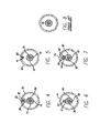
- FIG. 2 is a cross sectional view of the catheter shown in FIG. 1 , taken along lines 2 - 2 .
- FIG. 3 is a cross sectional view of the catheter shown in FIG. 1 , taken along lines 3 - 3 .
- FIG. 4 is a cross sectional view of an alternate embodiment of the catheter of the invention, having a mandrel lumen defined by a sidewall secured to the outer tubular member along a transverse length of the sidewall which is less than the diameter of the side wall.
- FIG. 5 is a cross sectional view of an alternate embodiment showing the support mandrel secured directly to the outer tubular member.
- FIG. 6 is a cross sectional view of an alternate embodiment showing the support mandrel secured directly to the inner tubular member.
- FIG. 7 is a cross sectional view of an alternate embodiment having a support mandrel lumen on an outer surface of an inner tubular member.
- FIG. 8 is a cross sectional view of a prior art catheter having a support mandrel.
- FIG. 9 is a schematic view of an embodiment of the invention which embodies features of the invention, having an intermediate support mandrel.
- FIG. 10 is an enlarged view of the catheter shown in FIG. 9 , taken within area 10 .
- FIG. 10 a is an enlarged view of an alternative embodiment of the catheter shown in FIG. 9 , having a sidewall defining a mandrel lumen within a proximal section of the outer tubular member.
- FIG. 11 is a cross sectional view taken along lines 11 - 11 .
- FIG. 12 is a schematic view of a catheter of the invention which embodies features of the invention, having rapid exchange capabilities.
- FIG. 13 is a cross sectional view of the catheter shown in FIG. 12 taken along lines 13 - 13 .
- FIG. 1 illustrates a balloon catheter 10 embodying features of the invention, having a proximal shaft portion 11 , a distal shaft portion 12 which is typically more flexible than proximal shaft portion 11 , an inner tubular member 13 , and an outer tubular member 14 .
- Inner tubular member 13 has a guidewire port 16 at its distal end and defines a guidewire lumen 18 configured to receive guidewire 20 , as best illustrated in FIGS. 2 and 3 , showing transverse cross sections of the catheter shaft taken along lines 2 - 2 and 3 - 3 , respectively.
- Outer tubular member 14 is coaxially disposed about inner tubular member 13 creating annular inflation lumen 22 .
- a balloon 24 preferably suitable for performing an angioplasty procedure has a proximal end disposed about and secured to a distal portion of outer tubular member 14 , a distal end disposed about and secured to a distal portion of the inner tubular member 13 , and an interior in fluid communication with inflation lumen 22 .
- Adapter 26 at the proximal end of catheter 10 provides fittings for access to inflation lumen 22 and guidewire lumen 18 .
- a sidewall 28 extends longitudinally along an interior surface of outer tubular member 14 , and is configured to define a mandrel lumen 30 .
- a mandrel 32 is disposed within mandrel lumen 30 .
- Sidewall 28 extends from the proximal end of the catheter shaft along at least a section of the proximal shaft section 11 .
- sidewall 28 distal end extends within the proximal shaft portion 11 .
- sidewall 28 may extend within the distal shaft portion 12 .
- the sidewall 28 extends within at least a section of the distal shaft portion 12 .
- the length of the sidewall 28 , and mandrel 32 therein, is about 2% to about 35% less than, and preferably about 15% to about 30% less than the length of the inner tubular member 13 .
- the sidewall 28 and mandrel 32 are typically about 50 cm to about 140 cm long, preferably about 100 cm to about 120 cm long, for a balloon catheter of about 145 cm in length.
- the mandrel 32 preferably extends through the proximal portion of the catheter so that it provides reinforcement and transmission of push through the aortic arch, but generally does not extend into the section of the catheter which extends within the coronary artery.
- the diameter of mandrel 32 may be adjusted as desired to achieve the desired handling characteristics, but generally should be about 0.005 to about 0.015 inch.
- the mandrel lumen 30 has an inner diameter not substantially larger than the diameter of the mandrel, i.e., about 10% to about 30%, preferably about 20% to about 25% greater than the mandrel diameter.
- the mandrel lumen is annular, although other configurations may be used depending on the shape of the mandrel.
- the mandrel 32 may have a tapered distal end.
- Mandrel 30 may be formed from metallic materials such as stainless steel and nickel titanium alloys, as well as other pseudo-elastic or shape-memory materials, and high modulus polymers such as PEEK, PEI, Nylon, and reinforced composite rod.
- the inner tubular member 13 and outer tubular member 14 of the catheters of the invention may be formed by conventional techniques, e.g. extruding, from materials already found useful in intravascular catheters such a polyethylene, polyamide, polyesters and composite materials.
- the use of the support mandrel allows the use of otherwise soft materials, such as polyamide block copolymers, co-polyesters, nylon and polyurethanes, which are compatible with materials used to form dilatation balloons. This facilitates the bonding of the outer 14 and inner 13 tubular members to the balloon 24 by conventional techniques, such as laser bonding.
- the catheter components can be bonded together by heat fusion, adhesive, or by other conventional means.
- adapter 26 has a third arm (not shown) providing access to mandrel lumen 30 so that mandrel 32 may be exchanged to vary the stiffness characteristics of catheter 10 to suit a given procedure.
- the proximal end of the mandrel 32 would extend out the proximal port in the third arm, to facilitate exchange of the mandrel.
- Mandrels having different flexibilities can be used and the length of the mandrel inserted into the catheter can be adjusted. For example, mandrels made from the different mandrel materials listed above, or having different diameters, may be exchanged to vary the stiffness of the catheter.
- mandrel lumen 30 is preferably sealed at the distal end of the lumen 30 .
- mandrel 32 may be fixed within lumen 30 , by heat deformation of sidewall 28 or with adhesive.
- FIGS. 4-7 illustrate alternative embodiments for securing the mandrel 32 to the catheter shaft.
- an outer tubular member 34 has a sidewall portion 36 defining a mandrel lumen 32 .
- the sidewall 36 is secured to the outer tubular member 14 along a transverse length of the sidewall 36 .
- the side wall 36 defining the mandrel lumen 32 has an outer diameter which is less than the outer diameter of the inner tubular member.
- FIG. 5 illustrates another embodiment having mandrel 40 secured directly to an inner surface of outer tubular member 42
- FIG. 6 illustrates an embodiment having a mandrel 44 secured along its length to an outer surface of the inner tubular member 46 .
- the mandrel 40 / 44 is secured using adhesive 41 or by heat fusing the polymer shaft to a polymeric mandrel.
- the mandrel 40 / 44 is secured along the mandrel length from the proximal end of the mandrel to the distal end of the mandrel.
- the mandrel is secured to the outer tubular member only at the proximal and the distal ends of the mandrel.
- FIG. 7 illustrates another embodiment having a longitudinally oriented sidewall portion 48 of inner tubular member 50 defining a mandrel lumen 52 .
- a mandrel 54 is contained within lumen 52 and either may be fixed or exchangeable/positionable through an adapter at the proximal end of the catheter, as discussed above.
- FIG. 8 illustrates a prior art over-the-wire catheter having a mandrel which is unsecured within the inflation lumen.
- Such prior art catheters have poor transfer of axial forces compared to the catheter of the invention.
- the mandrel has improved transfer of axial forces, thus allowing the wall thickness of the tubular members to be decreased, and consequently, the size of the inflation lumen for a given diameter catheter to be increased.
- the increased inflation lumen size provides for improved inflation/deflation times.
- the wall thickness of the inner tubular member is typically about 0.05 to about 0.2 mm, and the wall thickness of the outer tubular member is typically about 0.05 to about 0.5 mm, depending on the shaft material used.
- FIG. 9 illustrates another embodiment in which the mandrel may be confined to an intermediate section of the catheter to provide a transition between the proximal and distal portions of the catheter shaft.
- catheter 60 generally comprises inner tubular member 62 having a guidewire port 64 at the distal end and defining a lumen 66 for slidably receiving guidewire 68 , and outer tubular member 70 comprising a proximal portion 72 , an intermediate portion 74 and a distal portion 76 .
- Outer tubular member 70 is coaxially disposed over inner tubular member 62 creating annular inflation lumen 78 .
- Inflatable member 79 is in communication with inflation lumen 78 .
- Intermediate portion 74 of outer tubular member 70 is shown in sectional detail in FIG. 10 and in cross section in FIG. 11 .
- intermediate portion 74 comprises a sidewall portion 80 extending longitudinally along an inside surface, defining mandrel lumen 82 .
- a mandrel 84 is disposed within lumen 82 , providing a transition between proximal portion 72 and distal portion 76 .
- the mandrel 84 is typically fixed within the lumen 82 by raising the temperature of sidewall portion 80 to cause the material to flow into the ends of the lumen 82 .
- sidewall 80 has a proximal end at the proximal end of the intermediate portion, and a distal end at the distal end of the intermediate portion.
- the sidewall 80 may have a length less than the length of the intermediate section or greater than the length of the intermediate section when the proximal portion 72 or distal portion 76 has a sidewall defining a mandrel lumen adjacent to lumen 82 .
- the sidewall 80 and mandrel 84 therein are substantially shorter than the length of the catheter, i.e., about 5% to about 20% of the length of the catheter.
- the length of the sidewall 80 is typically about 5 to about 25 cm, preferably about 8 to about 20 cm.
- the length of the mandrel 84 is about 7 to about 27 cm, preferably about 10 to about 22 cm.
- the length of mandrel 84 may be varied to optimize the handling characteristics, with ends extending to or beyond the junctions between the intermediate portion 74 and the proximal portion 72 and distal portion 76 .
- the mandrel 84 is ground at each end to provide a taper. This smoothes the transition between materials and minimizes the chances of an end of the mandrel puncturing the catheter.
- the taper extends beyond the ends of the lumen 84 .
- the tapered sections of the mandrel begin beyond the ends of the lumen 84 .
- the taper may extend to the end of the mandrel, or alternatively, a constant diameter section may be located at each end of the mandrel which extends from an end of the taper to the end of the mandrel.
- the mandrel may be about 0% to about 200% longer than the lumen 84 , and is typically about 10% to about 30% longer than the lumen 84 .
- the mandrel may extend from either end of the lumen 84 , or from one end, as for example where mandrel extends only out the distal end of the lumen 84 .
- the intermediate portion should be about 10 cm, while the support mandrel should be about 22 cm, with about 5 cm of taper at each end.
- the support mandrel may be about 0.009 inches in diameter when formed from nickel titanium.
- the proximal portion of the catheter is about 3.2 F while the distal portion tapers to approximately 2.4 F.
- proximal tubular portion 72 , intermediate tubular portion 74 and distal tubular portion 76 are dimensioned so that the distal end of the mandrel is at, or does not extend beyond, the distal end of the guiding catheter used to introduce catheter 60 into the patient's vasculature.
- mandrel 84 supports catheter 60 as it bends through the aortic arch and enters the coronary artery.
- catheter 60 may exhibit a low stiffness, high stiffness, low stiffness profile corresponding to the proximal, intermediate, and distal portions of the catheter shaft.
- the intermediate portion 74 is stiffened by mandrel 84 , whereas the proximal 72 and distal 76 portions of catheter 60 are relatively soft since the guiding catheter can provide support for the proximal portion 72 and the distal portion 76 is formed of soft material to facilitate advancement in the coronary anatomy However, different characteristics may be obtained easily for different applications.
- the sidewall 30 / 80 does not allow uniform support of the tubular member, complicating the use of conventional marking techniques.
- the proximal portion 72 of outer tubular member 70 may be marked in a conventional manner. Additionally, the configuration provides for improved inflation/deflation times.
- the inner and outer tubular members may be formed from materials already found suitable for catheter manufacture.
- proximal, intermediate, and distal portions of the outer tubular member are formed of different materials providing a flexibility increasing from the proximal to the distal end of the catheter.
- proximal portion 72 is formed from a Nylon blend
- the intermediate portion 74 is formed from a Nylon
- the distal portion 76 is formed from a polyamide copolymer such as PEBAX.
- the inner tubular ember may have proximal, intermediate and distal portions similar to the outer tubular member.
- intermediate portion 74 does not have sidewall 80 , and the mandrel 84 is secured directly to the outer tubular member 70 or the inner tubular member 62 at the intermediate portion 74 .
- the mandrel 84 is bonded to the tubular member 70 / 62 with adhesive, although other conventional means of attachment may also be used.
- the mandrel 84 can be attached at two points adjacent its ends, at intermediate points or along its entire length.
- the adhered support mandrel is preferably used with catheter shafts having different materials for the proximal and distal outer tubular member portions, to ease the transition between the two materials.
- intermediate portion 74 is a separate section joined to the proximal and distal ends of the distal 76 and proximal 72 portions, respectively.
- the intermediate portion 74 extends within the proximal 72 and distal 76 portions, although other suitable joints may be used to join the shaft portions together.
- the intermediate portion 74 can be eliminated and the mandrel 84 may be confined to a location within the proximal end of the distal portion 76 , or the distal end of the proximal portion 72 , or it may extend from the proximal portion 72 to the distal portion 76
- catheter 86 is configured to have rapid exchange capabilities.
- catheter shaft 88 comprises an elongated proximal tubular member 90 which defines inflation lumen 92 .
- proximal tubular member 90 defines inflation lumen 92 .
- sidewall portion 94 that defines support mandrel lumen 96 .
- a proximal portion of inner tubular member 98 is adjacent to a distal portion of proximal tubular member.
- Distal tubular member 100 is coaxially disposed about proximal tubular member 90 and inner tubular member 98 .
- Distal tubular member 100 overlaps and seals the proximal portion of inner tubular member 98 and the distal portion of proximal tubular member 90 as shown in cross section in FIG. 13 .
- Distal tubular member defines a lumen 101 that is in communication with inflation lumen 92 .
- Adapter 102 at the proximal end of catheter shaft 88 provides access to inflation lumen 92 .
- An inflatable member 103 at the distal end of the catheter is likewise in communication with lumen 101 .
- Inner tubular member 98 defines guidewire lumen 104 and has a first guidewire port 106 at its proximal end and a second guidewire port 108 at its distal end configured to receive guidewire 109 .
- Support mandrel 110 is disposed within support mandrel lumen 96 and preferably is secured within the lumen but may also be exchangeable.
- Suitable materials may be used to fabricate the tubular members of the catheter shaft 88 .
- the support mandrel 110 is configured to give a level of reinforcement equivalent to convention rapid exchange catheters having a proximal hypotube.
- Presently preferred materials include stainless steel and nickel titanium alloys, with MP35N and 304 stainless steel particularly preferred.
- Mandrel 110 should have a length about equal to the proximal portion of the catheter, such as approximately 115 cm for a typical PTCA procedure. If desired, the distal portion of mandrel 110 can be radiused or tapered to maximize flexibility without causing kinking at the transition. Distal end of mandrel 110 can be about 20 to 25 cm from the distal end of the catheter.
Abstract
A catheter having a mandrel secured to the catheter or constrained within a dedicated lumen. In one embodiment, the catheter has an inner tubular member and an outer tubular member with a sidewall configured to define a mandrel lumen longitudinally along an inner surface of the outer tubular member or along an outer surface of the inner tubular member. The mandrel lumen may be configured to allow the mandrel to be exchanged to adjust the handling characteristics of the catheter. The mandrel may occupy an intermediate portion of the catheter shaft, or may extend from the proximal end to within proximal or distal shaft sections of the catheter. In coronary artery applications, the mandrel is configured to support the catheter as it bends through the aortic arch and enters the coronary artery.
Description
This application is a divisional of application Ser. No. 09/470,519, filed Dec. 22, 1999, issued May 11, 2004 as U.S. Pat. No. 6,733,486.
This invention relates to the field of medical devices, and more particularly to a balloon catheter having a reinforcing mandrel.
Catheters designed for intravascular procedures such as angioplasty have a number of desirable characteristics. Such catheters must be able to transmit force along the length of the catheter shaft to allow it to be pushed through the vasculature. However, the catheter shaft must also retain sufficient flexibility to allow it to track over a guidewire through the often tortuous vasculature. Additionally, the catheter also must be able to cross stenosed portions of the vascular anatomy.
To help meet the desire for a catheter having sufficient pushability and crossability, while maintaining trackability, prior art designs have supplemented polymer catheter shafts with a stiffening wire or mandrel. Other prior art designs have addressed these handling and performance issues by using materials of different stiffness for the proximal and distal portions of the catheter, and employing a high strength metallic proximal shaft section, commonly called a hypotube. To prevent kinking at the junction of these two materials, while maintaining trackability and pushability, some conventional designs have employed a stiffening wire to bridge the transition in catheter shaft material. Despite these attempts, prior art designs have suffered from various drawbacks. For example, support mandrels do not always transmit axial force effectively.
Accordingly, it would be a significant advance to provide a catheter having improved pushability and crossability while maintaining good trackability. This invention satisfies these and other needs.
The invention is directed to catheters having supporting mandrels to improve pushability and trackability. The mandrel is constrained within the catheter shaft by being located within a dedicated mandrel lumen or secured at least in part directly to the catheter shaft. The length and position of the mandrel within the catheter shaft may vary, so that the mandrel extends distally from the proximal end of the catheter shaft, or alternatively, from a location distal to the proximal end of the catheter shaft. The term mandrel should be understood to include a variety of different supporting members such as solid or hollow rods, wires, and the like.
One embodiment of the catheter of the invention comprises an inner tubular member defining a guidewire lumen and an outer tubular member coaxially or eccentrically disposed about the inner tubular member to form an annular inflation lumen, with a side wall which extends longitudinally within the annular inflation lumen and which defines a mandrel lumen configured to receive a mandrel therein. In a presently preferred embodiment, the sidewall extends along at least a portion of an inner surface of the outer tubular member. However, the sidewall may alternatively extend along at least a portion of an outer surface of the inner tubular member. The reinforcement provided by the mandrel improves pushability and columnar strength of the catheter shaft formed from relatively soft materials, while inhibiting or preventing shaft kinking. This aids manufacturing by offering better bonding to balloon materials and allows greater flexibility in catheter design. These designs also permit a reduction in wall thickness to maximize the inflation lumen. The mandrel lumen may be configured to allow the mandrel to be exchanged to adjust the handling characteristics of the catheter. Thus, in one embodiment, the mandrel lumen extends to the proximal end of the shaft to facilitate mandrel exchange. Alternatively, the mandrel may be secured within the lumen, at one or more points on the mandrel.
Another embodiment comprises a mandrel having a proximal end distal to the proximal end of the catheter shaft. In a presently preferred embodiment, the mandrel is in an intermediate portion of the shaft between proximal and distal shaft portions. The intermediate portion typically has a length less than the length of the proximal or the distal shaft sections. The mandrel may be within a sidewall portion defining a mandrel lumen or alternatively, may be secured to the catheter shaft at the proximal and distal ends of the mandrel, or along the length thereof from the proximal to the distal end of the mandrel. In a presently preferred embodiment, the mandrel is within the lumen of a side wall which extends longitudinally along at least a portion of an inner surface of the outer tubular member. The proximal and distal portions of the outer tubular member have conventional profiles, and form the inflation lumen in conjunction with the coaxial inner tubular member. The intermediate portion has a sidewall portion configured to define a mandrel lumen along its inner surface. The mandrel is typically secured within the lumen, preferably by heat deformation. In coronary artery applications, the mandrel is configured to support the catheter as it bends through the aortic arch and enters the coronary artery. Preferably, the portion of the catheter carrying the mandrel does not enter the coronary artery.
In other embodiments, the mandrel is secured along the length of the mandrel from the proximal to the distal end thereof directly to the inner tubular member or to the outer tubular member, without a sidewall mandrel lumen. In another embodiment, the catheter has rapid exchange capabilities and generally comprises an elongated proximal tubular member having a sidewall configured to define a mandrel lumen extending longitudinally along an inner surface of the proximal tubular member. An inner tubular member overlaps the distal portion of the proximal tubular member and provides a guidewire lumen with guidewire entry and exit ports. A distal tubular member secures the adjacent portions of the proximal tubular member and the inner tubular member and carries a balloon, such as a dilatation balloon, on the distal end. The support mandrel is disposed within the mandrel lumen. Restraining the support mandrel within the lumen provides superior transmission of axial forces to improve pushability. Moreover, the dedicated lumen addresses failure concerns by allowing the catheter to be withdrawn intact in case of a mandrel fracture. When the mandrel is not confined to a dedicated lumen, a fractured end could penetrate the catheter shaft or otherwise prevent its easy removal through the tortuous vasculature.
The catheter of the invention having a mandrel has excellent crossability and trackability. The mandrel connected to the catheter shaft directly or within the dedicated mandrel lumen provides effective transmission of axial force and avoids the entanglement of the mandrel around the inner tubular member by preventing movement of the mandrel within the annular lumen. The catheter of the invention also has a low profile shaft design, and provides suitable stiffness transitions between proximal and distal portions of the catheter to improve handling and performance and minimize kinking. These and other advantages of the invention will become more apparent from the following detailed description and exemplary drawings.
The diameter of mandrel 32 may be adjusted as desired to achieve the desired handling characteristics, but generally should be about 0.005 to about 0.015 inch. Preferably, the mandrel lumen 30 has an inner diameter not substantially larger than the diameter of the mandrel, i.e., about 10% to about 30%, preferably about 20% to about 25% greater than the mandrel diameter. In the embodiment illustrated in FIG. 1 , the mandrel lumen is annular, although other configurations may be used depending on the shape of the mandrel. The mandrel 32 may have a tapered distal end.
In certain embodiments, adapter 26 has a third arm (not shown) providing access to mandrel lumen 30 so that mandrel 32 may be exchanged to vary the stiffness characteristics of catheter 10 to suit a given procedure. The proximal end of the mandrel 32 would extend out the proximal port in the third arm, to facilitate exchange of the mandrel. Mandrels having different flexibilities can be used and the length of the mandrel inserted into the catheter can be adjusted. For example, mandrels made from the different mandrel materials listed above, or having different diameters, may be exchanged to vary the stiffness of the catheter. In the embodiment having an exchangeable mandrel, mandrel lumen 30 is preferably sealed at the distal end of the lumen 30. Alternatively, mandrel 32 may be fixed within lumen 30, by heat deformation of sidewall 28 or with adhesive.
In the embodiment illustrated in FIG. 9 , sidewall 80 has a proximal end at the proximal end of the intermediate portion, and a distal end at the distal end of the intermediate portion. However, the sidewall 80 may have a length less than the length of the intermediate section or greater than the length of the intermediate section when the proximal portion 72 or distal portion 76 has a sidewall defining a mandrel lumen adjacent to lumen 82. The sidewall 80 and mandrel 84 therein are substantially shorter than the length of the catheter, i.e., about 5% to about 20% of the length of the catheter. The length of the sidewall 80 is typically about 5 to about 25 cm, preferably about 8 to about 20 cm. The length of the mandrel 84 is about 7 to about 27 cm, preferably about 10 to about 22 cm. The length of mandrel 84 may be varied to optimize the handling characteristics, with ends extending to or beyond the junctions between the intermediate portion 74 and the proximal portion 72 and distal portion 76. In the embodiment illustrated in FIG. 9 , the mandrel 84 is ground at each end to provide a taper. This smoothes the transition between materials and minimizes the chances of an end of the mandrel puncturing the catheter. The taper extends beyond the ends of the lumen 84. In one embodiment illustrated in FIG. 10 , the tapered sections of the mandrel begin beyond the ends of the lumen 84. The taper may extend to the end of the mandrel, or alternatively, a constant diameter section may be located at each end of the mandrel which extends from an end of the taper to the end of the mandrel. The mandrel may be about 0% to about 200% longer than the lumen 84, and is typically about 10% to about 30% longer than the lumen 84. The mandrel may extend from either end of the lumen 84, or from one end, as for example where mandrel extends only out the distal end of the lumen 84. For a catheter about 143 cm in overall length, the intermediate portion should be about 10 cm, while the support mandrel should be about 22 cm, with about 5 cm of taper at each end. The support mandrel may be about 0.009 inches in diameter when formed from nickel titanium. The proximal portion of the catheter is about 3.2 F while the distal portion tapers to approximately 2.4 F.
Preferably, proximal tubular portion 72, intermediate tubular portion 74 and distal tubular portion 76 are dimensioned so that the distal end of the mandrel is at, or does not extend beyond, the distal end of the guiding catheter used to introduce catheter 60 into the patient's vasculature. Thus, mandrel 84 supports catheter 60 as it bends through the aortic arch and enters the coronary artery. In such embodiments, catheter 60 may exhibit a low stiffness, high stiffness, low stiffness profile corresponding to the proximal, intermediate, and distal portions of the catheter shaft. The intermediate portion 74 is stiffened by mandrel 84, whereas the proximal 72 and distal 76 portions of catheter 60 are relatively soft since the guiding catheter can provide support for the proximal portion 72 and the distal portion 76 is formed of soft material to facilitate advancement in the coronary anatomy However, different characteristics may be obtained easily for different applications.
It may be desirable to mark the catheter shaft for fluoroscopic visualization. However, the sidewall 30/80 does not allow uniform support of the tubular member, complicating the use of conventional marking techniques. By limiting the sidewall 80 of outer tubular member to the intermediate portion 74, the proximal portion 72 of outer tubular member 70 may be marked in a conventional manner. Additionally, the configuration provides for improved inflation/deflation times.
As discussed above, the inner and outer tubular members may be formed from materials already found suitable for catheter manufacture. In one preferred embodiment, proximal, intermediate, and distal portions of the outer tubular member are formed of different materials providing a flexibility increasing from the proximal to the distal end of the catheter. In a presently preferred embodiment, proximal portion 72, is formed from a Nylon blend, the intermediate portion 74 is formed from a Nylon, and the distal portion 76 is formed from a polyamide copolymer such as PEBAX. The inner tubular ember may have proximal, intermediate and distal portions similar to the outer tubular member.
In an alternative embodiment (not shown), intermediate portion 74 does not have sidewall 80, and the mandrel 84 is secured directly to the outer tubular member 70 or the inner tubular member 62 at the intermediate portion 74. Preferably, the mandrel 84 is bonded to the tubular member 70/62 with adhesive, although other conventional means of attachment may also be used. The mandrel 84 can be attached at two points adjacent its ends, at intermediate points or along its entire length. The adhered support mandrel is preferably used with catheter shafts having different materials for the proximal and distal outer tubular member portions, to ease the transition between the two materials.
In the embodiment illustrated in FIG. 9 , intermediate portion 74 is a separate section joined to the proximal and distal ends of the distal 76 and proximal 72 portions, respectively. The intermediate portion 74 extends within the proximal 72 and distal 76 portions, although other suitable joints may be used to join the shaft portions together. Alternatively, the intermediate portion 74 can be eliminated and the mandrel 84 may be confined to a location within the proximal end of the distal portion 76, or the distal end of the proximal portion 72, or it may extend from the proximal portion 72 to the distal portion 76
In yet another embodiment of the invention, shown in FIGS. 12 and 13 , catheter 86 is configured to have rapid exchange capabilities. Generally catheter shaft 88 comprises an elongated proximal tubular member 90 which defines inflation lumen 92. Along an inner surface of proximal tubular member 90 is a longitudinally oriented sidewall portion 94 that defines support mandrel lumen 96. A proximal portion of inner tubular member 98 is adjacent to a distal portion of proximal tubular member. Distal tubular member 100 is coaxially disposed about proximal tubular member 90 and inner tubular member 98. Accordingly, the proximal end of distal tubular member 100 overlaps and seals the proximal portion of inner tubular member 98 and the distal portion of proximal tubular member 90 as shown in cross section in FIG. 13 . Distal tubular member defines a lumen 101 that is in communication with inflation lumen 92. Adapter 102 at the proximal end of catheter shaft 88 provides access to inflation lumen 92. An inflatable member 103 at the distal end of the catheter is likewise in communication with lumen 101. Inner tubular member 98 defines guidewire lumen 104 and has a first guidewire port 106 at its proximal end and a second guidewire port 108 at its distal end configured to receive guidewire 109. Support mandrel 110 is disposed within support mandrel lumen 96 and preferably is secured within the lumen but may also be exchangeable.
Suitable materials, such as those already discussed, may be used to fabricate the tubular members of the catheter shaft 88. Generally, the support mandrel 110 is configured to give a level of reinforcement equivalent to convention rapid exchange catheters having a proximal hypotube. Presently preferred materials include stainless steel and nickel titanium alloys, with MP35N and 304 stainless steel particularly preferred. Mandrel 110 should have a length about equal to the proximal portion of the catheter, such as approximately 115 cm for a typical PTCA procedure. If desired, the distal portion of mandrel 110 can be radiused or tapered to maximize flexibility without causing kinking at the transition. Distal end of mandrel 110 can be about 20 to 25 cm from the distal end of the catheter.
While the present invention is described herein in terms of certain preferred embodiments, those skilled in the art will recognize that various modifications and improvements may be made to the invention without departing from the scope thereof. Moreover, although individual features of one embodiment of the invention may be discussed herein or shown in the drawings of the one embodiment and not in other embodiments, it should be apparent that individual features of one embodiment may be combined with one or more features of another embodiment or features from a plurality of embodiments.
Claims (15)
1. A catheter for performing an intravascular procedure, comprising
a) a catheter shaft comprising an inner and outer tubular member fixedly secured together, and the inner tubular member defines a first lumen located within the inner tubular member, and the inner tubular member has an outer diameter that is smaller than an outer diameter of the outer tubular member, and the inner tubular member is disposed within the outer tubular member such that a second ring-shaped lumen extends between an inner surface of the outer tubular member and an outer surface of the inner tubular member;
b) a side wall which extends longitudinally along the outer surface of at least a portion of the inner tubular member within the second lumen and which defines a third lumen configured to receive a mandrel, and which is radially spaced apart from the inner surface of the outer tubular member by the second lumen extending fully around an inner circumference of the outer tubular member, the side wall having an outer diameter measured through a center of the third lumen that is smaller than an outer diameter of the inner tubular member measured through a center of the first lumen; and
c) a mandrel in the third lumen.
2. The catheter claim 1 , wherein the mandrel has tapered ends.
3. The catheter of claim 2 , wherein the tapered ends of the mandrel are about 1 to about 7 centimeters long.
4. The catheter of claim 1 , wherein the mandrel is about 7 to about 120 centimeters long.
5. The catheter of claim 1 , wherein the mandrel is secured within the mandrel lumen by heat deformation of the sidewall.
6. The catheter of claim 1 , wherein the mandrel lumen has an inner diameter which is not substantially larger than an outer diameter of the mandrel.
7. The catheter of claim 1 , wherein the mandrel lumen proximal end is distal to the proximal end of the catheter inner tubular member.
8. The catheter of claim 7 , wherein the mandrel lumen is about 0.5 to about 15 centimeters long.
9. The catheter of claim 7 wherein the inner tubular member has a proximal portion, a distal portion, and an intermediate portion therebetween, and wherein the mandrel lumen is within the intermediate portion.
10. The catheter of claim 9 , wherein the intermediate portion with the mandrel within the mandrel lumen therein is relatively more stiff than the proximal portion and the distal portion.
11. The catheter of claim 1 wherein the mandrel lumen extends to the proximal end of the inner tubular member.
12. The catheter of claim 11 wherein the mandrel lumen is about 110 to about 125 cm long.
13. The catheter of claim 11 , wherein the mandrel is exchangeable.
14. The catheter of claim 1 wherein the mandrel has a length substantially shorter than a length of the catheter.
15. The catheter of claim 1 wherein the third lumen has a length substantially shorter than a length of the catheter.
Priority Applications (1)
| Application Number | Priority Date | Filing Date | Title |
|---|---|---|---|
| US10/692,365 US7351238B2 (en) | 1999-12-22 | 2003-10-22 | Catheter having a reinforcing mandrel |
Applications Claiming Priority (2)
| Application Number | Priority Date | Filing Date | Title |
|---|---|---|---|
| US09/470,519 US6733486B1 (en) | 1999-12-22 | 1999-12-22 | Catheter having a reinforcing mandrel |
| US10/692,365 US7351238B2 (en) | 1999-12-22 | 2003-10-22 | Catheter having a reinforcing mandrel |
Related Parent Applications (1)
| Application Number | Title | Priority Date | Filing Date |
|---|---|---|---|
| US09/470,519 Division US6733486B1 (en) | 1999-12-22 | 1999-12-22 | Catheter having a reinforcing mandrel |
Publications (2)
| Publication Number | Publication Date |
|---|---|
| US20040082935A1 US20040082935A1 (en) | 2004-04-29 |
| US7351238B2 true US7351238B2 (en) | 2008-04-01 |
Family
ID=23867931
Family Applications (2)
| Application Number | Title | Priority Date | Filing Date |
|---|---|---|---|
| US09/470,519 Expired - Lifetime US6733486B1 (en) | 1999-12-22 | 1999-12-22 | Catheter having a reinforcing mandrel |
| US10/692,365 Expired - Fee Related US7351238B2 (en) | 1999-12-22 | 2003-10-22 | Catheter having a reinforcing mandrel |
Family Applications Before (1)
| Application Number | Title | Priority Date | Filing Date |
|---|---|---|---|
| US09/470,519 Expired - Lifetime US6733486B1 (en) | 1999-12-22 | 1999-12-22 | Catheter having a reinforcing mandrel |
Country Status (4)
| Country | Link |
|---|---|
| US (2) | US6733486B1 (en) |
| JP (2) | JP4249925B2 (en) |
| AU (1) | AU2270401A (en) |
| WO (1) | WO2001045782A2 (en) |
Cited By (7)
| Publication number | Priority date | Publication date | Assignee | Title |
|---|---|---|---|---|
| US20110060276A1 (en) * | 2007-09-12 | 2011-03-10 | Cook Incoporated | Balloon catheter for delivering a therapeutic agent |
| US20110137245A1 (en) * | 2007-09-12 | 2011-06-09 | Cook Medical Technologies Llc | Balloon catheter with embedded rod |
| US8673007B2 (en) | 2010-04-20 | 2014-03-18 | Warsaw Orthopedic, Inc. | Implant with insertion device and method |
| US9956384B2 (en) | 2014-01-24 | 2018-05-01 | Cook Medical Technologies Llc | Articulating balloon catheter and method for using the same |
| US10070412B1 (en) | 2017-04-20 | 2018-09-04 | At&T Intellectual Property I, L.P. | Paging based on individual user mobility patterns |
| US10286190B2 (en) | 2013-12-11 | 2019-05-14 | Cook Medical Technologies Llc | Balloon catheter with dynamic vessel engaging member |
| US20210220605A1 (en) * | 2020-01-21 | 2021-07-22 | Becton, Dickinson And Company | Tubular instrument and related devices and methods |
Families Citing this family (43)
| Publication number | Priority date | Publication date | Assignee | Title |
|---|---|---|---|---|
| US6488689B1 (en) | 1999-05-20 | 2002-12-03 | Aaron V. Kaplan | Methods and apparatus for transpericardial left atrial appendage closure |
| US7118551B1 (en) * | 1999-12-22 | 2006-10-10 | Advanced Cardiovascular Systems, Inc. | Non-metal reinforcing mandrel |
| US6733486B1 (en) * | 1999-12-22 | 2004-05-11 | Advanced Cardiovascular Systems, Inc. | Catheter having a reinforcing mandrel |
| US6663648B1 (en) * | 2000-06-15 | 2003-12-16 | Cordis Corporation | Balloon catheter with floating stiffener, and procedure |
| US6929652B1 (en) | 2001-06-01 | 2005-08-16 | Advanced Cardiovascular Systems, Inc. | Delivery and recovery systems having steerability and rapid exchange operating modes for embolic protection systems |
| US6837870B2 (en) * | 2002-07-23 | 2005-01-04 | Advanced Cardiovascular Systems, Inc. | Catheter having a multilayered shaft section with a reinforcing mandrel |
| US7195611B1 (en) * | 2002-12-31 | 2007-03-27 | Advanced Cardiovascular Systems, Inc. | Rapid exchange balloon catheter having a reinforced inner tubular member |
| US20050182386A1 (en) * | 2004-02-17 | 2005-08-18 | Steen Aggerholm | Catheter with stiffening element |
| US9289576B2 (en) * | 2004-06-17 | 2016-03-22 | W. L. Gore & Associates, Inc. | Catheter assembly |
| EP1787673B1 (en) * | 2004-08-11 | 2019-05-22 | Kaneka Corporation | Catheter |
| US20060156998A1 (en) * | 2005-01-19 | 2006-07-20 | Shawn Bridy | Protective collar for animals |
| US20060258987A1 (en) * | 2005-05-10 | 2006-11-16 | Cook Incorporated | Catheter stiffening member |
| WO2009114556A2 (en) * | 2005-10-04 | 2009-09-17 | Ilh, Llc | Catheters with lubricious linings and methods for making and using them |
| US20080171980A1 (en) * | 2007-01-16 | 2008-07-17 | Medtronic Vascular, Inc. | Proximal Shaft for Rapid Exchange Catheter |
| US7815601B2 (en) | 2007-02-05 | 2010-10-19 | Boston Scientific Scimed, Inc. | Rapid exchange enteral stent delivery system |
| EP2148623A1 (en) * | 2007-05-21 | 2010-02-03 | Epitek, Inc. | Left atrial appendage closure |
| US20080294175A1 (en) * | 2007-05-21 | 2008-11-27 | Epitek, Inc. | Left atrial appendage closure |
| US8177753B2 (en) * | 2007-06-01 | 2012-05-15 | Arrow International, Inc. | Catheter insertion assembly |
| US8821477B2 (en) * | 2007-08-06 | 2014-09-02 | Boston Scientific Scimed, Inc. | Alternative micromachined structures |
| GB2471517B (en) * | 2009-07-02 | 2011-09-21 | Cook William Europ | Implant deployment catheter |
| US20110092918A1 (en) * | 2009-10-19 | 2011-04-21 | Ferrosan A/S | Malleable tip for applying an agent to a target site |
| WO2011133736A2 (en) | 2010-04-21 | 2011-10-27 | The Regents Of The University Of Michigan | Fluoroscopy-independent, endovascular aortic occlusion system |
| US9504802B2 (en) * | 2010-07-19 | 2016-11-29 | Sukhjit Gill | Guiding catheter stabilization system |
| US8834510B2 (en) | 2011-05-26 | 2014-09-16 | Abbott Cardiovascular Systems Inc. | Catheter with stepped skived hypotube |
| JP5743270B2 (en) * | 2011-07-13 | 2015-07-01 | 朝日インテック株式会社 | catheter |
| US9474882B2 (en) * | 2013-02-26 | 2016-10-25 | Prytime Medical Devices, Inc. | Fluoroscopy-independent balloon guided occlusion catheter and methods |
| US9974925B2 (en) * | 2013-03-12 | 2018-05-22 | Boston Scientific Scimed, Inc. | Catheter shaft constructions having contrast fluid lumen |
| CA2923419A1 (en) * | 2013-09-09 | 2015-03-12 | Pryor Medical Devices, Inc. | Low-profile occlusion catheter |
| US9868242B2 (en) | 2014-04-25 | 2018-01-16 | Medtronic Ablation Frontiers Llc | Methods of manufacturing a multi-lumen device |
| US9505159B2 (en) | 2014-04-25 | 2016-11-29 | Medtronic Ablation Frontiers Llc | Methods of dimensionally stabilizing a lumen of a multi-lumen device during manufacture |
| US10076634B2 (en) | 2014-04-25 | 2018-09-18 | Medtronic Ablation Frontiers Llc | Multi-lumen device with non collapsable minor lumen |
| EP3077036A4 (en) | 2014-06-10 | 2017-04-19 | Pryor Medical Devices, Inc. | Conduit guiding tip |
| CN105536121B (en) | 2014-09-04 | 2020-06-05 | 雅培心血管系统有限公司 | Balloon catheter |
| CN105582611B (en) | 2014-09-04 | 2020-03-03 | 雅培心血管系统有限公司 | Balloon catheter |
| JP6304886B2 (en) * | 2014-10-28 | 2018-04-04 | 日本ライフライン株式会社 | Balloon catheter |
| EP3270997B1 (en) | 2015-03-19 | 2019-07-03 | Prytime Medical Devices, Inc. | System for low-profile occlusion balloon catheter |
| CR20150458A (en) | 2015-05-19 | 2015-12-14 | Abbott Cardiovascular Systems | BALL CATHETER |
| CN205322986U (en) | 2015-05-19 | 2016-06-22 | 雅培心血管系统有限公司 | Utricule pipe with integral multilayer distally external member |
| EP4302815A3 (en) | 2016-06-02 | 2024-03-27 | Prytime Medical Devices, Inc. | System and method for low-profile occlusion ballon catheter |
| WO2018132623A1 (en) | 2017-01-12 | 2018-07-19 | The Regents Of The University Of California | Endovascular perfusion augmentation for critical care |
| CA3060519A1 (en) | 2017-04-21 | 2018-10-25 | The Regents Of The University Of California | Aortic flow meter and pump for partial-aortic occlusion |
| US11850174B2 (en) * | 2018-12-27 | 2023-12-26 | Lifetech Scientific (Shenzhen) Co, Ltd. | Delivery apparatus and system |
| EP4121159A2 (en) | 2020-03-16 | 2023-01-25 | Certus Critical Care, Inc. | Blood flow control devices, systems, and methods and error detection thereof |
Citations (26)
| Publication number | Priority date | Publication date | Assignee | Title |
|---|---|---|---|---|
| US4762129A (en) | 1984-11-23 | 1988-08-09 | Tassilo Bonzel | Dilatation catheter |
| US4979951A (en) | 1984-05-30 | 1990-12-25 | Simpson John B | Atherectomy device and method |
| WO1992017236A1 (en) | 1991-04-05 | 1992-10-15 | Boston Scientific Corporation | Adjustably stiffenable convertible catheter assembly |
| EP0515119A1 (en) | 1991-05-23 | 1992-11-25 | Scimed Life Systems, Inc. | Intravascular device |
| US5180367A (en) | 1989-09-06 | 1993-01-19 | Datascope Corporation | Procedure and balloon catheter system for relieving arterial or veinal restrictions without exchanging balloon catheters |
| US5224933A (en) | 1992-03-23 | 1993-07-06 | C. R. Bard, Inc. | Catheter purge device |
| US5242396A (en) | 1991-12-19 | 1993-09-07 | Advanced Cardiovascular Systems, Inc. | Dilatation catheter with reinforcing mandrel |
| US5387193A (en) | 1994-02-09 | 1995-02-07 | Baxter International Inc. | Balloon dilation catheter with hypotube |
| US5425711A (en) | 1988-02-29 | 1995-06-20 | Scimed Life Systems, Inc. | Intravascular catheter with distal guide wire lumen and transition member |
| US5507768A (en) | 1991-01-28 | 1996-04-16 | Advanced Cardiovascular Systems, Inc. | Stent delivery system |
| US5531690A (en) | 1992-10-30 | 1996-07-02 | Cordis Corporation | Rapid exchange catheter |
| WO1996020752A1 (en) | 1995-01-04 | 1996-07-11 | Advanced Cardiovascular Systems, Inc. | Catheter shaft with an oblong transverse cross section |
| US5549552A (en) | 1995-03-02 | 1996-08-27 | Scimed Life Systems, Inc. | Balloon dilation catheter with improved pushability, trackability and crossability |
| US5562620A (en) * | 1994-04-01 | 1996-10-08 | Localmed, Inc. | Perfusion shunt device having non-distensible pouch for receiving angioplasty balloon |
| US5607394A (en) | 1993-10-07 | 1997-03-04 | Boston Scientific Corp. | Dilatation catheter having a field stylet |
| US5634902A (en) * | 1995-02-01 | 1997-06-03 | Cordis Corporation | Dilatation catheter with side aperture |
| EP0832670A1 (en) | 1996-08-29 | 1998-04-01 | Advanced Cardiovascular Systems, Inc. | Radiation delivery catheter with reinforcing mandrel |
| EP0835673A2 (en) | 1996-10-10 | 1998-04-15 | Schneider (Usa) Inc. | Catheter for tissue dilatation and drug delivery |
| US5795325A (en) | 1991-07-16 | 1998-08-18 | Heartport, Inc. | Methods and apparatus for anchoring an occluding member |
| US5810867A (en) | 1997-04-28 | 1998-09-22 | Medtronic, Inc. | Dilatation catheter with varied stiffness |
| US5823995A (en) | 1992-08-25 | 1998-10-20 | Bard Connaught | Dilatation catheter with stiffening wire anchored in the vicinity of the guide wire port |
| US5868706A (en) | 1994-12-27 | 1999-02-09 | Advanced Cardiovascular Systems, Inc. | Catheter with reinforced oblong transverse cross section |
| US5882336A (en) | 1994-12-30 | 1999-03-16 | Janacek; Jaroslav | Dilation catheter |
| US5897536A (en) | 1996-09-24 | 1999-04-27 | Cordis Europa, N.V. | Catheter having a controllable stiffness and adapted for use with various contrast media |
| US6733486B1 (en) * | 1999-12-22 | 2004-05-11 | Advanced Cardiovascular Systems, Inc. | Catheter having a reinforcing mandrel |
| US20060129178A1 (en) * | 1991-04-05 | 2006-06-15 | Nikolaus Reifart | Adjustably stiffenable convertible catheter assembly |
Family Cites Families (4)
| Publication number | Priority date | Publication date | Assignee | Title |
|---|---|---|---|---|
| US4651751A (en) * | 1982-10-14 | 1987-03-24 | American Hospital Supply Corporation | Guiding catheter and method of use |
| US5490837A (en) * | 1991-07-05 | 1996-02-13 | Scimed Life Systems, Inc. | Single operator exchange catheter having a distal catheter shaft section |
| EP1346748B1 (en) * | 1995-02-24 | 2006-04-05 | Medtronic Vascular Connaught | Dilatation catheter |
| JPH0938208A (en) * | 1995-07-27 | 1997-02-10 | Sumitomo Bakelite Co Ltd | Aortic balloon catheter with suction route for injection of cardiac muscle protecting fluid |
-
1999
- 1999-12-22 US US09/470,519 patent/US6733486B1/en not_active Expired - Lifetime
-
2000
- 2000-12-14 JP JP2001546720A patent/JP4249925B2/en not_active Expired - Fee Related
- 2000-12-14 AU AU22704/01A patent/AU2270401A/en not_active Abandoned
- 2000-12-14 WO PCT/US2000/034169 patent/WO2001045782A2/en active Application Filing
-
2003
- 2003-10-22 US US10/692,365 patent/US7351238B2/en not_active Expired - Fee Related
-
2006
- 2006-10-30 JP JP2006294612A patent/JP2007014820A/en active Pending
Patent Citations (29)
| Publication number | Priority date | Publication date | Assignee | Title |
|---|---|---|---|---|
| US4979951A (en) | 1984-05-30 | 1990-12-25 | Simpson John B | Atherectomy device and method |
| US4762129B1 (en) | 1984-11-23 | 1991-07-02 | Tassilo Bonzel | |
| US4762129A (en) | 1984-11-23 | 1988-08-09 | Tassilo Bonzel | Dilatation catheter |
| US5425711A (en) | 1988-02-29 | 1995-06-20 | Scimed Life Systems, Inc. | Intravascular catheter with distal guide wire lumen and transition member |
| US5180367A (en) | 1989-09-06 | 1993-01-19 | Datascope Corporation | Procedure and balloon catheter system for relieving arterial or veinal restrictions without exchanging balloon catheters |
| US5507768A (en) | 1991-01-28 | 1996-04-16 | Advanced Cardiovascular Systems, Inc. | Stent delivery system |
| WO1992017236A1 (en) | 1991-04-05 | 1992-10-15 | Boston Scientific Corporation | Adjustably stiffenable convertible catheter assembly |
| US20060129178A1 (en) * | 1991-04-05 | 2006-06-15 | Nikolaus Reifart | Adjustably stiffenable convertible catheter assembly |
| EP0515119A1 (en) | 1991-05-23 | 1992-11-25 | Scimed Life Systems, Inc. | Intravascular device |
| US5795325A (en) | 1991-07-16 | 1998-08-18 | Heartport, Inc. | Methods and apparatus for anchoring an occluding member |
| US5242396A (en) | 1991-12-19 | 1993-09-07 | Advanced Cardiovascular Systems, Inc. | Dilatation catheter with reinforcing mandrel |
| US5224933A (en) | 1992-03-23 | 1993-07-06 | C. R. Bard, Inc. | Catheter purge device |
| US5823995A (en) | 1992-08-25 | 1998-10-20 | Bard Connaught | Dilatation catheter with stiffening wire anchored in the vicinity of the guide wire port |
| US5531690A (en) | 1992-10-30 | 1996-07-02 | Cordis Corporation | Rapid exchange catheter |
| US5931812A (en) | 1993-10-07 | 1999-08-03 | Boston Scientific Corporation | Dilatation catheter |
| US5607394A (en) | 1993-10-07 | 1997-03-04 | Boston Scientific Corp. | Dilatation catheter having a field stylet |
| US5387193A (en) | 1994-02-09 | 1995-02-07 | Baxter International Inc. | Balloon dilation catheter with hypotube |
| US5562620A (en) * | 1994-04-01 | 1996-10-08 | Localmed, Inc. | Perfusion shunt device having non-distensible pouch for receiving angioplasty balloon |
| US5868706A (en) | 1994-12-27 | 1999-02-09 | Advanced Cardiovascular Systems, Inc. | Catheter with reinforced oblong transverse cross section |
| US5882336A (en) | 1994-12-30 | 1999-03-16 | Janacek; Jaroslav | Dilation catheter |
| WO1996020752A1 (en) | 1995-01-04 | 1996-07-11 | Advanced Cardiovascular Systems, Inc. | Catheter shaft with an oblong transverse cross section |
| US5634902A (en) * | 1995-02-01 | 1997-06-03 | Cordis Corporation | Dilatation catheter with side aperture |
| US5549552A (en) | 1995-03-02 | 1996-08-27 | Scimed Life Systems, Inc. | Balloon dilation catheter with improved pushability, trackability and crossability |
| US5782740A (en) | 1996-08-29 | 1998-07-21 | Advanced Cardiovascular Systems, Inc. | Radiation dose delivery catheter with reinforcing mandrel |
| EP0832670A1 (en) | 1996-08-29 | 1998-04-01 | Advanced Cardiovascular Systems, Inc. | Radiation delivery catheter with reinforcing mandrel |
| US5897536A (en) | 1996-09-24 | 1999-04-27 | Cordis Europa, N.V. | Catheter having a controllable stiffness and adapted for use with various contrast media |
| EP0835673A2 (en) | 1996-10-10 | 1998-04-15 | Schneider (Usa) Inc. | Catheter for tissue dilatation and drug delivery |
| US5810867A (en) | 1997-04-28 | 1998-09-22 | Medtronic, Inc. | Dilatation catheter with varied stiffness |
| US6733486B1 (en) * | 1999-12-22 | 2004-05-11 | Advanced Cardiovascular Systems, Inc. | Catheter having a reinforcing mandrel |
Cited By (10)
| Publication number | Priority date | Publication date | Assignee | Title |
|---|---|---|---|---|
| US20110060276A1 (en) * | 2007-09-12 | 2011-03-10 | Cook Incoporated | Balloon catheter for delivering a therapeutic agent |
| US20110137245A1 (en) * | 2007-09-12 | 2011-06-09 | Cook Medical Technologies Llc | Balloon catheter with embedded rod |
| US8182446B2 (en) | 2007-09-12 | 2012-05-22 | Cook Medical Technologies | Balloon catheter for delivering a therapeutic agent |
| US8784602B2 (en) | 2007-09-12 | 2014-07-22 | Cook Medical Technologies Llc | Balloon catheter for delivering a therapeutic agent |
| US8673007B2 (en) | 2010-04-20 | 2014-03-18 | Warsaw Orthopedic, Inc. | Implant with insertion device and method |
| US10286190B2 (en) | 2013-12-11 | 2019-05-14 | Cook Medical Technologies Llc | Balloon catheter with dynamic vessel engaging member |
| US9956384B2 (en) | 2014-01-24 | 2018-05-01 | Cook Medical Technologies Llc | Articulating balloon catheter and method for using the same |
| US10070412B1 (en) | 2017-04-20 | 2018-09-04 | At&T Intellectual Property I, L.P. | Paging based on individual user mobility patterns |
| US10492170B2 (en) | 2017-04-20 | 2019-11-26 | At&T Intellectual Property I, L.P. | Paging based on individual user mobility patterns |
| US20210220605A1 (en) * | 2020-01-21 | 2021-07-22 | Becton, Dickinson And Company | Tubular instrument and related devices and methods |
Also Published As
| Publication number | Publication date |
|---|---|
| JP2003517897A (en) | 2003-06-03 |
| JP2007014820A (en) | 2007-01-25 |
| US6733486B1 (en) | 2004-05-11 |
| AU2270401A (en) | 2001-07-03 |
| WO2001045782A2 (en) | 2001-06-28 |
| JP4249925B2 (en) | 2009-04-08 |
| WO2001045782A3 (en) | 2002-01-03 |
| US20040082935A1 (en) | 2004-04-29 |
Similar Documents
| Publication | Publication Date | Title |
|---|---|---|
| US7351238B2 (en) | Catheter having a reinforcing mandrel | |
| US6589207B1 (en) | Rapid exchange catheter having a support mandrel | |
| US5300025A (en) | Dilatation catheter having a coil supported inflation lumen | |
| US7037291B2 (en) | Catheter shaft junction having a polymeric reinforcing member with a high glass transition temperature | |
| US8221444B2 (en) | Catheter having an improved distal tip | |
| EP0850084B1 (en) | Catheter with reinforced oblong transverse cross section | |
| US6746423B1 (en) | Catheter having improved rapid exchange junction | |
| US6960188B2 (en) | Catheter having enhanced distal pushability | |
| US5242396A (en) | Dilatation catheter with reinforcing mandrel | |
| US5154725A (en) | Easily exchangeable catheter system | |
| JPH09503411A (en) | Dilatation catheter |
Legal Events
| Date | Code | Title | Description |
|---|---|---|---|
| STCF | Information on status: patent grant |
Free format text: PATENTED CASE |
|
| CC | Certificate of correction | ||
| FPAY | Fee payment |
Year of fee payment: 4 |
|
| FPAY | Fee payment |
Year of fee payment: 8 |
|
| FEPP | Fee payment procedure |
Free format text: MAINTENANCE FEE REMINDER MAILED (ORIGINAL EVENT CODE: REM.); ENTITY STATUS OF PATENT OWNER: LARGE ENTITY |
|
| LAPS | Lapse for failure to pay maintenance fees |
Free format text: PATENT EXPIRED FOR FAILURE TO PAY MAINTENANCE FEES (ORIGINAL EVENT CODE: EXP.); ENTITY STATUS OF PATENT OWNER: LARGE ENTITY |
|
| STCH | Information on status: patent discontinuation |
Free format text: PATENT EXPIRED DUE TO NONPAYMENT OF MAINTENANCE FEES UNDER 37 CFR 1.362 |
|
| FP | Lapsed due to failure to pay maintenance fee |
Effective date: 20200401 |