US7274439B2 - Precise, no-contact, position sensing using imaging - Google Patents
Precise, no-contact, position sensing using imaging Download PDFInfo
- Publication number
- US7274439B2 US7274439B2 US11/004,743 US474304A US7274439B2 US 7274439 B2 US7274439 B2 US 7274439B2 US 474304 A US474304 A US 474304A US 7274439 B2 US7274439 B2 US 7274439B2
- Authority
- US
- United States
- Prior art keywords
- sensor assembly
- inertial sensor
- images
- spherical
- velocity
- Prior art date
- Legal status (The legal status is an assumption and is not a legal conclusion. Google has not performed a legal analysis and makes no representation as to the accuracy of the status listed.)
- Active
Links
- 238000003384 imaging method Methods 0.000 title description 4
- 230000003287 optical effect Effects 0.000 claims abstract description 34
- 238000001514 detection method Methods 0.000 claims abstract description 31
- 238000000034 method Methods 0.000 claims description 19
- 238000006073 displacement reaction Methods 0.000 claims description 16
- 238000012545 processing Methods 0.000 claims description 7
- 241000699666 Mus <mouse, genus> Species 0.000 description 28
- 238000005259 measurement Methods 0.000 description 4
- 241000699670 Mus sp. Species 0.000 description 3
- 230000008859 change Effects 0.000 description 3
- 238000010586 diagram Methods 0.000 description 3
- 230000008901 benefit Effects 0.000 description 2
- 238000004891 communication Methods 0.000 description 2
- 238000012937 correction Methods 0.000 description 2
- 238000005516 engineering process Methods 0.000 description 2
- 238000004519 manufacturing process Methods 0.000 description 2
- 238000012544 monitoring process Methods 0.000 description 2
- 230000009467 reduction Effects 0.000 description 2
- 230000006978 adaptation Effects 0.000 description 1
- 238000004458 analytical method Methods 0.000 description 1
- 238000003491 array Methods 0.000 description 1
- 238000004364 calculation method Methods 0.000 description 1
- 230000008878 coupling Effects 0.000 description 1
- 238000010168 coupling process Methods 0.000 description 1
- 238000005859 coupling reaction Methods 0.000 description 1
- 238000013500 data storage Methods 0.000 description 1
- 238000012634 optical imaging Methods 0.000 description 1
- 230000008569 process Effects 0.000 description 1
- 238000004886 process control Methods 0.000 description 1
- 239000002994 raw material Substances 0.000 description 1
Images


Classifications
-
- G—PHYSICS
- G06—COMPUTING; CALCULATING OR COUNTING
- G06F—ELECTRIC DIGITAL DATA PROCESSING
- G06F3/00—Input arrangements for transferring data to be processed into a form capable of being handled by the computer; Output arrangements for transferring data from processing unit to output unit, e.g. interface arrangements
- G06F3/01—Input arrangements or combined input and output arrangements for interaction between user and computer
- G06F3/03—Arrangements for converting the position or the displacement of a member into a coded form
- G06F3/0304—Detection arrangements using opto-electronic means
- G06F3/0317—Detection arrangements using opto-electronic means in co-operation with a patterned surface, e.g. absolute position or relative movement detection for an optical mouse or pen positioned with respect to a coded surface
-
- G—PHYSICS
- G01—MEASURING; TESTING
- G01C—MEASURING DISTANCES, LEVELS OR BEARINGS; SURVEYING; NAVIGATION; GYROSCOPIC INSTRUMENTS; PHOTOGRAMMETRY OR VIDEOGRAMMETRY
- G01C19/00—Gyroscopes; Turn-sensitive devices using vibrating masses; Turn-sensitive devices without moving masses; Measuring angular rate using gyroscopic effects
- G01C19/02—Rotary gyroscopes
- G01C19/04—Details
- G01C19/28—Pick-offs, i.e. devices for taking-off an indication of the displacement of the rotor axis
-
- G—PHYSICS
- G01—MEASURING; TESTING
- G01C—MEASURING DISTANCES, LEVELS OR BEARINGS; SURVEYING; NAVIGATION; GYROSCOPIC INSTRUMENTS; PHOTOGRAMMETRY OR VIDEOGRAMMETRY
- G01C21/00—Navigation; Navigational instruments not provided for in groups G01C1/00 - G01C19/00
- G01C21/10—Navigation; Navigational instruments not provided for in groups G01C1/00 - G01C19/00 by using measurements of speed or acceleration
- G01C21/12—Navigation; Navigational instruments not provided for in groups G01C1/00 - G01C19/00 by using measurements of speed or acceleration executed aboard the object being navigated; Dead reckoning
- G01C21/16—Navigation; Navigational instruments not provided for in groups G01C1/00 - G01C19/00 by using measurements of speed or acceleration executed aboard the object being navigated; Dead reckoning by integrating acceleration or speed, i.e. inertial navigation
- G01C21/166—Mechanical, construction or arrangement details of inertial navigation systems
-
- G—PHYSICS
- G01—MEASURING; TESTING
- G01C—MEASURING DISTANCES, LEVELS OR BEARINGS; SURVEYING; NAVIGATION; GYROSCOPIC INSTRUMENTS; PHOTOGRAMMETRY OR VIDEOGRAMMETRY
- G01C25/00—Manufacturing, calibrating, cleaning, or repairing instruments or devices referred to in the other groups of this subclass
- G01C25/005—Manufacturing, calibrating, cleaning, or repairing instruments or devices referred to in the other groups of this subclass initial alignment, calibration or starting-up of inertial devices
-
- G—PHYSICS
- G01—MEASURING; TESTING
- G01P—MEASURING LINEAR OR ANGULAR SPEED, ACCELERATION, DECELERATION, OR SHOCK; INDICATING PRESENCE, ABSENCE, OR DIRECTION, OF MOVEMENT
- G01P3/00—Measuring linear or angular speed; Measuring differences of linear or angular speeds
- G01P3/36—Devices characterised by the use of optical means, e.g. using infrared, visible, or ultraviolet light
-
- G—PHYSICS
- G01—MEASURING; TESTING
- G01P—MEASURING LINEAR OR ANGULAR SPEED, ACCELERATION, DECELERATION, OR SHOCK; INDICATING PRESENCE, ABSENCE, OR DIRECTION, OF MOVEMENT
- G01P3/00—Measuring linear or angular speed; Measuring differences of linear or angular speeds
- G01P3/64—Devices characterised by the determination of the time taken to traverse a fixed distance
- G01P3/68—Devices characterised by the determination of the time taken to traverse a fixed distance using optical means, i.e. using infrared, visible, or ultraviolet light
-
- G—PHYSICS
- G01—MEASURING; TESTING
- G01P—MEASURING LINEAR OR ANGULAR SPEED, ACCELERATION, DECELERATION, OR SHOCK; INDICATING PRESENCE, ABSENCE, OR DIRECTION, OF MOVEMENT
- G01P3/00—Measuring linear or angular speed; Measuring differences of linear or angular speeds
- G01P3/64—Devices characterised by the determination of the time taken to traverse a fixed distance
- G01P3/80—Devices characterised by the determination of the time taken to traverse a fixed distance using auto-correlation or cross-correlation detection means
- G01P3/806—Devices characterised by the determination of the time taken to traverse a fixed distance using auto-correlation or cross-correlation detection means in devices of the type to be classified in G01P3/68
-
- G—PHYSICS
- G01—MEASURING; TESTING
- G01S—RADIO DIRECTION-FINDING; RADIO NAVIGATION; DETERMINING DISTANCE OR VELOCITY BY USE OF RADIO WAVES; LOCATING OR PRESENCE-DETECTING BY USE OF THE REFLECTION OR RERADIATION OF RADIO WAVES; ANALOGOUS ARRANGEMENTS USING OTHER WAVES
- G01S11/00—Systems for determining distance or velocity not using reflection or reradiation
- G01S11/12—Systems for determining distance or velocity not using reflection or reradiation using electromagnetic waves other than radio waves
-
- G—PHYSICS
- G06—COMPUTING; CALCULATING OR COUNTING
- G06F—ELECTRIC DIGITAL DATA PROCESSING
- G06F3/00—Input arrangements for transferring data to be processed into a form capable of being handled by the computer; Output arrangements for transferring data from processing unit to output unit, e.g. interface arrangements
- G06F3/01—Input arrangements or combined input and output arrangements for interaction between user and computer
- G06F3/03—Arrangements for converting the position or the displacement of a member into a coded form
- G06F3/0304—Detection arrangements using opto-electronic means
- G06F3/0312—Detection arrangements using opto-electronic means for tracking the rotation of a spherical or circular member, e.g. optical rotary encoders used in mice or trackballs using a tracking ball or in mouse scroll wheels
-
- G—PHYSICS
- G06—COMPUTING; CALCULATING OR COUNTING
- G06T—IMAGE DATA PROCESSING OR GENERATION, IN GENERAL
- G06T7/00—Image analysis
- G06T7/20—Analysis of motion
- G06T7/246—Analysis of motion using feature-based methods, e.g. the tracking of corners or segments
Definitions
- the present invention generally relates to the field of motion sensors and in particular to contact free optical motion sensing for inertial reference systems.
- Precision inertial navigation systems typically require concentric sets of ball bearing supported gimbals which allow instruments to freely rotate in flight maneuvers and allow them to be manipulated for calibration.
- the embodiments of the previously referenced '6540 Application which is herein incorporated by reference, eliminate the need for gimbals and ball bearings by supporting the inertial sensor assembly with a spherically shaped gas bearing.
- the gas bearing allows rotation of the inertial sensor assembly in all axes with no wear due to contact between rotating surfaces.
- the need arises to sense the motion of the inertial sensor assembly without physical contact between the sensor and the assembly.
- An optical computer mouse is one example of a low cost sensor that detects relative movement with respect to a flat surface without the need for physical contact between the mouse and the surface.
- the optical mouse system includes an image acquisition system (IAS) and a digital signal processor (DSP).
- IAS image acquisition system
- DSP digital signal processor
- the IAS forms an image of the microscopic textural features of the surface below the sensor. A sequence of these images is taken quickly so that the sequential pictures overlap.
- the images are processed by the DSP to determine the relative direction and distance of motion between the surface and the sensor.
- the DSP further produces a stream of relative delta-x and delta-y displacement values along the x and y axis.
- the resulting displacement data is provided by the output of the mouse to the computer.
- the data is used by the computer to relocate an on-screen pointer in coordination with movement of the mouse.
- Embodiments of the present invention address the problem of sensing and measuring the movement of an object, where physical contact with the object is undesirable, through the use of optical imaging.
- a motion detection system In one embodiment, a motion detection system is disclosed.
- One or more optical sensors each generate image signals of an object.
- a controller is coupled with each sensor to receive the image signals and adapted to apply a delta detection algorithm to the image signals to determine the distance and direction the object has moved. The controller further calculates the velocity of the object's movement based on a time sequence between the received series of image signals and the distance moved.
- another motion detection system is disclosed.
- One or more image acquisition systems are adapted to produce a series of overlapping images of the object.
- a controller is coupled to receive the series of overlapping images from each image acquisition system. The controller measures the elapsed time between images in the series, and applies a delta detection algorithm to the series of overlapping images in order to determine the distance and direction the object has moved. The controller calculates the velocity of the object's movement based on the elapsed time between images and the distance moved.
- a rotational displacement sensing apparatus for an inertial navigation system containing a gas bearing supported spherical inertial sensor assembly containing a gas bearing supported spherical inertial sensor assembly.
- One or more image acquisition systems are adapted to produce a series of overlapping images of the inertial sensor assembly.
- a controller coupled to receive the series of overlapping images applies a delta detection algorithm to the series of overlapping images to determine the distance, the direction of movement of the inertial sensor assembly and the resulting relative position of the gas bearing supported spherical inertial sensor assembly.
- the controller further calculates the rotational velocity of the inertial sensor assembly based on a time sequence between the received series of image signals and the distance moved.
- a method for precisely determining the relative movement and velocity of a moving object comprising capturing a first image of the object precisely at a first known time; capturing a second image of the object precisely at second known time such that the first and second images are taken in sufficiently proximate times that the first and second images are overlapping images of the object; and processing the first and second images through a delta detection algorithm, where the delta detection algorithm determines how far the object has moved, the direction of movement, and the rate of change in position of the object.
- another method for precisely determining the relative movement and velocity of a moving object comprising capturing a first image of the object; associating a time stamp reference to the first image; capturing a second image of the object, where the first and second images are taken in sufficiently proximate times so that the first and second images are overlapping images of the object; associating a time stamp reference to the second image; determining the direction of movement and distance moved by the object by applying a delta detection algorithm to the images; and determining the velocity of the object based on the distance moved and the difference in time between the time stamp references associated with the images.
- another method for precisely determining the relative movement and velocity of a moving object comprising capturing a plurality of images of the object; where each image is taken in sufficiently proximate time so that subsequent images are overlapping images of the object; associating a time stamp reference to each of the images captured; determining the direction of movement and distance moved by the object by applying a delta detection algorithm to the images; and determining the velocity of the object based on the distance moved and the difference in time between the time stamp references associated with the images.
- another method for precisely determining the relative movement and velocity of a moving object comprising aligning an optical computer mouse sensor to the surface of an object; coupling the optical mouse sensor to a computer I/O port; accumulating x-axis and y-axis displacement data communicated by the optical computer mouse sensor to the computer I/O port, from time T 1 to time T 2 ; calculating the distance and direction of movement of the object, the average velocity of movement, and the resulting relative position of the object.
- another motion detection system is disclosed.
- One or more optical computer mice are aligned to capture images of an object.
- a computer is coupled to receive x-axis and y-axis displacement data generated by the mice and to accumulate the x-axis and y-axis displacement over a time interval.
- the computer is further adapted to calculate the distance and direction of movement of the object, the average velocity of movement, and the resulting relative position of the object.
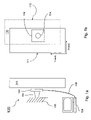
- FIGS. 1 a and 1 b are diagrams illustrating precise, no-contact, position sensing using imaging, with an object having a planar surface.
- FIG. 1 a is a side view of the current invention and
- FIG. 1 b is a front view of the current invention;
- FIG. 2 is a diagram illustrating precise, no-contact, position sensing using imaging, with an object having a spherical surface, of the current invention
- FIG. 3 is a flow chart illustrating the processing of data in one embodiment of the current invention
- FIG. 4 is a diagram illustrating the combination of precise, no-contact, position sensing using imaging, in combination with a gas supported inertial sensor assembly
- FIG. 5 is a flow chart of one embodiment of the present invention.
- Precision inertial navigation systems typically require concentric sets of ball bearing supported gimbals which allow instruments to freely rotate in flight maneuvers and allow them to be manipulated for calibration.
- the embodiments of the previously referenced commonly assigned '6540 Application which is herein incorporated by reference, eliminate the need for gimbals and ball bearings by supporting the inertial sensor assembly with a spherically shaped gas bearing.
- the gas bearing allows rotation of the inertial sensor assembly in all axes with no wear due to contact between rotating surfaces.
- the gas bearing eliminates physical reference points provided by the gimbals, and because physical contact with the freely rotating inertial sensor assembly is undesirable, the need arises to sense the motion, velocity and position of the inertial sensor assembly, without physical contact between the sensor and the assembly.
- the embodiments of the present invention address the problems of contact free motion sensing by applying optical navigation technology to create precision, no-contact motion sensing.
- FIGS. 1 a and 1 b a motion detection system 100 of one embodiment of the present invention is illustrated.
- FIG. 1 a is a side view of the motion detection system 100 adapted to determine the precise relative motion of the surface of an object 110 with respect to the optical sensor 102 .
- FIG. 1 b is a front view of the same embodiment.
- An optical sensor 102 also commonly referred to as an image acquisition system, is rigidly connected by a mounting bracket 104 to a fixed reference structure 106 .
- the output of the optical sensor 102 is connected 109 with a controller 108 .
- the optical sensor 102 captures a sequence of overlapping images of the subject object 110 and communicates these images to the controller 108 .
- the controller applies a delta detection algorithm to the sequence of images which determines how common features in the images moved from one image to the next, along the x-axis and y-axis.
- the delta detection algorithm determines the distance and direction that the object 110 has moved and calculates its new position 112 relative to its previous position 111 .
- the controller creates a time stamp for each image by incorporating data on the relative time each image was captured. By associating a time stamp with each image the time elapsed between images is known.
- the velocity of the object's movement is then calculated by the controller.
- the resulting velocity, direction, and displacement output is then available to other systems for such applications as process controls or process monitoring, or as error correction feedback data.
- FIG. 2 a motion detection system 200 of another embodiment of the present invention is illustrated.
- the subject object is a sphere 202 that is free to rotate 204 about an axis 206 .
- An optical sensor 202 also commonly referred to as an image acquisition system, is rigidly connected by a mounting bracket 204 to a fixed reference structure 206 .
- the output of the optical sensor 202 is connected 209 with a controller 208 .
- the optical sensor 202 captures a sequence of overlapping images of the subject object 210 and communicates these images to the controller 208 .
- the x-axis and y-axis displacement data provided by delta detection algorithm is used by the controller 208 to determine the sphere's angle of rotation, its speed of rotation, and the resulting sphere position relative to the previous position.
- FIG. 2 only illustrates the subject object rotating about a single axis, this motion detection system can be applied to a spherical object rotating on multiple axes.
- Embodiments of the present invention can be used for applications such as measuring the position or movement of raw material in a manufacturing process, for sensing the position of gyroscopes with respect to a fixed housing, robot motion sensing for feedback control, sensing product position in assembly and production facilities, or other systems requiring precision, contact-free, position sensing.
- a motion detection system 300 of another embodiment of the present invention is illustrated, precisely detecting the motion and velocity of an object using an off the shelf computer optical mouse sensor 301 coupled 303 to an Intel based personal computer (PC) running the Microsoft Windows operating system 302 .
- the optical navigation technology creates a sequence of images 301 - 1 of the surface of an object in front of the sensor.
- a digital signal processor 301 - 2 generates a stream of x-axis and y-axis displacement values proportional to the relative movement of the surface of the object with respect to the sensor. These displacement values are formatted by the PS/2 output converter 301 - 3 into the proper protocol to communicate the values to a standard PS/2 mouse I/O device port.
- the data from the optical mouse sensor 301 is received at the PS/2 mouse I/O device port 302 - 1 .
- This embodiment of the present invention includes a software program running on the PC 302 which enables the mouse sensor 301 to be used as a precision motion measurement instrument instead of a pointing device.
- the program receives the data from the PS/2 mouse I/O port 302 - 1 by applying Microsoft's DirectInput application programming interface (API) 302 - 2 .
- Microsoft's DirectInput API is an application programming interface for input devices that communicates directly with device hardware drivers and gives faster access to input data than by relying on Microsoft Windows messages. Because DirectInput works directly with the mouse driver, it bypasses the Microsoft Windows subsystem that normally interprets mouse data for windows applications.
- the software program accumulates the linear x-axis and y-axis displacement values 302 - 3 it receives from the PS/2 mouse I/O device port 302 - 1 and then calculates the distance and direction of movement, the average velocity of movement, and the resulting new relative position of the object 302 - 4 .
- the optical mouse sensor 301 and the PC 302 can communicate via a standard universal serial bus, wirelessly, or through other communication standards, rather than through the PS/2 mouse port.
- the optical mouse sensor 301 can be an assembly constructed from individual component parts rather than an off-the-shelf optical computer mouse.
- the computer system processing the data can be comprised of any computer system configured to communicate with the optical mouse sensor 301 .
- the mathematical algorithms 302 - 3 can be adjusted to map the x-axis and y-axis displacement data into spherical coordinates, cylindrical coordinates, or other system of coordinates in order to calculate the objects direction and distance of movement and the new relative position of the object.
- a motion detection system 401 in combination with the Gas Supported Inertial Sensor Assembly 400 of the '6540 Application of the preferred embodiment of the present invention is illustrated.
- a gas supported inertial navigation system (INS) 400 utilizes a freely rotating spherically shaped inertial sensor assembly (ISA) 408 .
- the ISA is supported, or floats, within a spherically shaped gas bearing 402 generated by a plurality of gas pads 404 - 1 , 404 - 2 (only two of which are shown in FIG. 4 ).
- Pressurized gas is applied to the gas pads 404 - 1 , 404 - 2 and the ISA 408 rides supported on a cushion of gas with little or no contacts between the ISA and the gas pads.
- the gas is air.
- the frictionless gas bearing 402 allows the ISA 408 to rotate on all axes 416 .
- optical sensors 406 and 414 are secured to the outer shell assembly 410 of the INS 400 by brackets 413 and 415 . Additional details regarding the gas bearing 402 , gas pads 404 and the INS 400 are found in the '6540 Application herein incorporated by reference.
- Overlapping images of the inertial sensor assembly 408 are captured by the optical sensors 406 , 414 and communicated 411 , 417 to a controller 412 where the images are processed through a delta detection algorithm to determine delta-x and delta-y displacement of the images, and the relative change in position between the outer shell assembly 410 and the ISA 408 .
- the controller also calculates the velocity of rotation of the inertial sensor assembly 408 based on the precise time each image was captured.
- the controller in this embodiment analyses images from two optical sensors 406 , 414 . Incorporating data from two or more optical sensors allows implementation of better error correction algorithms.
- FIG. 5 a method for precisely determining the relative motion of a moving object 500 of an embodiment of the present invention is illustrated.
- the method comprising: capturing a first image of the object at time T 1 ( 501 ); capturing a second image of the object precisely at time T 2 ( 502 ), where the first and second images are taken in sufficiently proximate times so that the first and second images are overlapping images of the object.
- controller element of the current invention includes, but are not limited to, digital computer systems, programmable controllers, or field programmable gate arrays. Therefore other embodiments of the present invention are program instructions resident on computer readable media which when implemented by such controllers, enable the controllers to implement embodiments of the present invention.
- Computer readable media include any form of computer memory, including but not limited to magnetic disk or tape, CD-ROMs, DVD-ROMs, or any optical data storage system, flash ROM, non-volatile ROM, or RAM.
Abstract
A contact free optical motion sensor for an inertial reference system. One or more image acquisition systems are adapted to produce a series of overlapping images of a gas bearing supported spherical inertial sensor assembly. A controller coupled to receive the series of overlapping images applies a delta detection algorithm to the series of overlapping images to determine the distance, the direction of movement of the inertial sensor assembly and the resulting relative position of the gas bearing supported spherical inertial sensor assembly. The controller further calculates the rotational velocity of the inertial sensor assembly based on a time sequence between the received series of image signals and the distance moved.
Description
This application is related to and claims the benefit of the filing date of U.S. Provisional Application No. 60/608,819 filed on Sep. 10, 2004, entitled GENERALIZED INERTIAL MEASUREMENT ERROR REDUCTION THROUGH MULTIPLE AXIS ROTATION DURING FLIGHT, which is incorporated herein by reference.
This application is related to co-pending U.S. patent application Honeywell docket number H0006540-1628, filed on even date herewith and entitled “GAS SUPPORTED INERTIAL SENSOR SYSTEM AND METHOD” (the '6540 Application). The '6540 Application is incorporated herein by reference.
This application is also related to the following applications filed on even date herewith, all of which are hereby incorporated herein by reference:
U.S. patent application Honeywell docket number H0007169-1628, entitled “SPHERICAL POSITION MONITORING SYSTEM,” (the '7169 Application);
U.S. patent application Honeywell docket number H0007167-1628, entitled “ABSOLUTE POSITION DETERMINATION OF AN OBJECT USING PATERN RECOGNITION,” (the '7167 Application);
U.S. patent application Honeywell docket number H0007194-1628, entitled “THREE DIMENSIONAL BALANCE ASSEMBLY,” (the '7194 Application);
U.S. patent application Honeywell docket number H0006475-1628, entitled “ARTICULATED GAS BEARING SUPPORT PADS,” (the '6475 Application);
U.S. patent application Honeywell docket number H0006535-1628, entitled “GAS JET CONTROL FOR INERTIAL MEASUREMENT UNIT,” (the '6535 Application);
U.S. patent application Honeywell docket number H0006345-1628, entitled “RF WIRELESS COMMUNICATION FOR DEEPLY EMBEDDED AEROSPACE SYSTEMS,” (the '6345 Application); and
U.S. patent application Honeywell docket number H0006368-1628, entitled “GENERALIZED INERTIAL MEASUREMENT ERROR REDUCTION THROUGH MULTIPLE AXIS ROTATION DURING FLIGHT,” (the '6368 Application).
The present invention generally relates to the field of motion sensors and in particular to contact free optical motion sensing for inertial reference systems.
Precision inertial navigation systems typically require concentric sets of ball bearing supported gimbals which allow instruments to freely rotate in flight maneuvers and allow them to be manipulated for calibration. The embodiments of the previously referenced '6540 Application, which is herein incorporated by reference, eliminate the need for gimbals and ball bearings by supporting the inertial sensor assembly with a spherically shaped gas bearing. The gas bearing allows rotation of the inertial sensor assembly in all axes with no wear due to contact between rotating surfaces. However, because physical contact with the freely rotating inertial sensor assembly is undesirable, the need arises to sense the motion of the inertial sensor assembly without physical contact between the sensor and the assembly.
An optical computer mouse is one example of a low cost sensor that detects relative movement with respect to a flat surface without the need for physical contact between the mouse and the surface. The optical mouse system includes an image acquisition system (IAS) and a digital signal processor (DSP). The IAS forms an image of the microscopic textural features of the surface below the sensor. A sequence of these images is taken quickly so that the sequential pictures overlap. The images are processed by the DSP to determine the relative direction and distance of motion between the surface and the sensor. The DSP further produces a stream of relative delta-x and delta-y displacement values along the x and y axis. The resulting displacement data is provided by the output of the mouse to the computer. The data is used by the computer to relocate an on-screen pointer in coordination with movement of the mouse.
The algorithms translating mouse movement into cursor movement are nonlinear in order to aid the user with quickly selecting the desired object on the monitor. A human viewing the computer screen and operating the mouse provides the required feedback loop to ensure that cursor controlled by the mouse is accurately positioned on the screen. Precise calculations of the exact distance, direction and velocity of relative motion between the mouse sensor and surface are not necessary for this application and thus are not determined. For these reasons, the optical navigation system applied by optical computer mice is inadequate in applications where the precise direction and distance of displacement and velocity of an object is required.
For the reasons stated above and for other reasons stated below which will become apparent to those skilled in the art upon reading and understanding the specification, there is a need in the art for contact free precision motion detection system.
The Embodiments of the present invention address the problem of sensing and measuring the movement of an object, where physical contact with the object is undesirable, through the use of optical imaging.
In one embodiment, a motion detection system is disclosed. One or more optical sensors each generate image signals of an object. A controller is coupled with each sensor to receive the image signals and adapted to apply a delta detection algorithm to the image signals to determine the distance and direction the object has moved. The controller further calculates the velocity of the object's movement based on a time sequence between the received series of image signals and the distance moved.
In another embodiment, another motion detection system is disclosed. One or more image acquisition systems are adapted to produce a series of overlapping images of the object. A controller is coupled to receive the series of overlapping images from each image acquisition system. The controller measures the elapsed time between images in the series, and applies a delta detection algorithm to the series of overlapping images in order to determine the distance and direction the object has moved. The controller calculates the velocity of the object's movement based on the elapsed time between images and the distance moved.
In another embodiment, a rotational displacement sensing apparatus for an inertial navigation system containing a gas bearing supported spherical inertial sensor assembly is disclosed. One or more image acquisition systems are adapted to produce a series of overlapping images of the inertial sensor assembly. A controller coupled to receive the series of overlapping images applies a delta detection algorithm to the series of overlapping images to determine the distance, the direction of movement of the inertial sensor assembly and the resulting relative position of the gas bearing supported spherical inertial sensor assembly. The controller further calculates the rotational velocity of the inertial sensor assembly based on a time sequence between the received series of image signals and the distance moved.
In still another embodiment, a method for precisely determining the relative movement and velocity of a moving object is disclosed. The method comprising capturing a first image of the object precisely at a first known time; capturing a second image of the object precisely at second known time such that the first and second images are taken in sufficiently proximate times that the first and second images are overlapping images of the object; and processing the first and second images through a delta detection algorithm, where the delta detection algorithm determines how far the object has moved, the direction of movement, and the rate of change in position of the object.
In still another embodiment, another method for precisely determining the relative movement and velocity of a moving object is disclosed. The method comprising capturing a first image of the object; associating a time stamp reference to the first image; capturing a second image of the object, where the first and second images are taken in sufficiently proximate times so that the first and second images are overlapping images of the object; associating a time stamp reference to the second image; determining the direction of movement and distance moved by the object by applying a delta detection algorithm to the images; and determining the velocity of the object based on the distance moved and the difference in time between the time stamp references associated with the images.
In yet another embodiment, another method for precisely determining the relative movement and velocity of a moving object is disclosed. The method comprising capturing a plurality of images of the object; where each image is taken in sufficiently proximate time so that subsequent images are overlapping images of the object; associating a time stamp reference to each of the images captured; determining the direction of movement and distance moved by the object by applying a delta detection algorithm to the images; and determining the velocity of the object based on the distance moved and the difference in time between the time stamp references associated with the images.
In yet another embodiment, another method for precisely determining the relative movement and velocity of a moving object is disclosed. The method comprising aligning an optical computer mouse sensor to the surface of an object; coupling the optical mouse sensor to a computer I/O port; accumulating x-axis and y-axis displacement data communicated by the optical computer mouse sensor to the computer I/O port, from time T1 to time T2; calculating the distance and direction of movement of the object, the average velocity of movement, and the resulting relative position of the object.
In still another embodiment, another motion detection system is disclosed. One or more optical computer mice are aligned to capture images of an object. A computer is coupled to receive x-axis and y-axis displacement data generated by the mice and to accumulate the x-axis and y-axis displacement over a time interval. The computer is further adapted to calculate the distance and direction of movement of the object, the average velocity of movement, and the resulting relative position of the object.
In yet another embodiment, a method for precisely determining the relative movement and velocity of a moving object, where the method is embedded in a computer-readable medium is disclosed. The method comprising capturing a first image of an object precisely at a first known time; capturing a second image of the object precisely at second known time, where the first and second images are taken in sufficiently proximate times so that the first and second images are overlapping images of the object; processing the first and second images through a delta detection algorithm, where the delta detection algorithm determines how far the object has moved, the direction of movement; and calculating the velocity of the object.
The present invention can be more easily understood and further advantages and uses thereof more readily apparent, when considered in view of the description of the preferred embodiments and the following figures in which:
In accordance with common practice, the various described features are not drawn to scale but are drawn to emphasize features relevant to the present invention. Reference characters denote like elements throughout Figures and text.
In the following detailed description, reference is made to the accompanying drawings that form a part hereof, and in which is shown by way of illustration specific illustrative embodiments in which the invention may be practiced. These embodiments are described in sufficient detail to enable those skilled in the art to practice the invention, and it is to be understood that other embodiments may be utilized and that logical, mechanical and electrical changes may be made without departing from the spirit and scope of the present invention. The following detailed description is, therefore, not to be taken in a limiting sense.
Precision inertial navigation systems typically require concentric sets of ball bearing supported gimbals which allow instruments to freely rotate in flight maneuvers and allow them to be manipulated for calibration. The embodiments of the previously referenced commonly assigned '6540 Application, which is herein incorporated by reference, eliminate the need for gimbals and ball bearings by supporting the inertial sensor assembly with a spherically shaped gas bearing. The gas bearing allows rotation of the inertial sensor assembly in all axes with no wear due to contact between rotating surfaces. However, because the gas bearing eliminates physical reference points provided by the gimbals, and because physical contact with the freely rotating inertial sensor assembly is undesirable, the need arises to sense the motion, velocity and position of the inertial sensor assembly, without physical contact between the sensor and the assembly. The embodiments of the present invention address the problems of contact free motion sensing by applying optical navigation technology to create precision, no-contact motion sensing.
In FIGS. 1 a and 1 b, a motion detection system 100 of one embodiment of the present invention is illustrated. FIG. 1 a is a side view of the motion detection system 100 adapted to determine the precise relative motion of the surface of an object 110 with respect to the optical sensor 102. FIG. 1 b is a front view of the same embodiment. An optical sensor 102, also commonly referred to as an image acquisition system, is rigidly connected by a mounting bracket 104 to a fixed reference structure 106. The output of the optical sensor 102 is connected 109 with a controller 108. The optical sensor 102 captures a sequence of overlapping images of the subject object 110 and communicates these images to the controller 108. The controller applies a delta detection algorithm to the sequence of images which determines how common features in the images moved from one image to the next, along the x-axis and y-axis. The delta detection algorithm then determines the distance and direction that the object 110 has moved and calculates its new position 112 relative to its previous position 111. Additionally, the controller creates a time stamp for each image by incorporating data on the relative time each image was captured. By associating a time stamp with each image the time elapsed between images is known. The velocity of the object's movement is then calculated by the controller. The resulting velocity, direction, and displacement output is then available to other systems for such applications as process controls or process monitoring, or as error correction feedback data.
In FIG. 2 , a motion detection system 200 of another embodiment of the present invention is illustrated. In this embodiment, the subject object is a sphere 202 that is free to rotate 204 about an axis 206. An optical sensor 202, also commonly referred to as an image acquisition system, is rigidly connected by a mounting bracket 204 to a fixed reference structure 206. The output of the optical sensor 202 is connected 209 with a controller 208. The optical sensor 202 captures a sequence of overlapping images of the subject object 210 and communicates these images to the controller 208. In this embodiment, the x-axis and y-axis displacement data provided by delta detection algorithm is used by the controller 208 to determine the sphere's angle of rotation, its speed of rotation, and the resulting sphere position relative to the previous position. Although FIG. 2 only illustrates the subject object rotating about a single axis, this motion detection system can be applied to a spherical object rotating on multiple axes. Embodiments of the present invention can be used for applications such as measuring the position or movement of raw material in a manufacturing process, for sensing the position of gyroscopes with respect to a fixed housing, robot motion sensing for feedback control, sensing product position in assembly and production facilities, or other systems requiring precision, contact-free, position sensing.
In FIG. 3 , a motion detection system 300 of another embodiment of the present invention is illustrated, precisely detecting the motion and velocity of an object using an off the shelf computer optical mouse sensor 301 coupled 303 to an Intel based personal computer (PC) running the Microsoft Windows operating system 302. Internal to the optical mouse sensor 301, the optical navigation technology creates a sequence of images 301-1 of the surface of an object in front of the sensor. A digital signal processor 301-2 generates a stream of x-axis and y-axis displacement values proportional to the relative movement of the surface of the object with respect to the sensor. These displacement values are formatted by the PS/2 output converter 301-3 into the proper protocol to communicate the values to a standard PS/2 mouse I/O device port. At the PC 302, the data from the optical mouse sensor 301 is received at the PS/2 mouse I/O device port 302-1. This embodiment of the present invention includes a software program running on the PC 302 which enables the mouse sensor 301 to be used as a precision motion measurement instrument instead of a pointing device. The program receives the data from the PS/2 mouse I/O port 302-1 by applying Microsoft's DirectInput application programming interface (API) 302-2. Microsoft's DirectInput API is an application programming interface for input devices that communicates directly with device hardware drivers and gives faster access to input data than by relying on Microsoft Windows messages. Because DirectInput works directly with the mouse driver, it bypasses the Microsoft Windows subsystem that normally interprets mouse data for windows applications. The software program accumulates the linear x-axis and y-axis displacement values 302-3 it receives from the PS/2 mouse I/O device port 302-1 and then calculates the distance and direction of movement, the average velocity of movement, and the resulting new relative position of the object 302-4.
In other embodiments, the optical mouse sensor 301 and the PC 302 can communicate via a standard universal serial bus, wirelessly, or through other communication standards, rather than through the PS/2 mouse port. In other embodiments, the optical mouse sensor 301 can be an assembly constructed from individual component parts rather than an off-the-shelf optical computer mouse. Moreover, instead of a PC 302 the computer system processing the data can be comprised of any computer system configured to communicate with the optical mouse sensor 301. Because the surface of the object observed by the optical mouse sensor 301 may be either linearly flat in the x-y plane, or may be a nonlinear surface such as a sphere, in other embodiments, the mathematical algorithms 302-3 can be adjusted to map the x-axis and y-axis displacement data into spherical coordinates, cylindrical coordinates, or other system of coordinates in order to calculate the objects direction and distance of movement and the new relative position of the object.
In FIG. 4 , a motion detection system 401, in combination with the Gas Supported Inertial Sensor Assembly 400 of the '6540 Application of the preferred embodiment of the present invention is illustrated. A gas supported inertial navigation system (INS) 400 utilizes a freely rotating spherically shaped inertial sensor assembly (ISA) 408. The ISA is supported, or floats, within a spherically shaped gas bearing 402 generated by a plurality of gas pads 404-1, 404-2 (only two of which are shown in FIG. 4 ). Pressurized gas is applied to the gas pads 404-1, 404-2 and the ISA 408 rides supported on a cushion of gas with little or no contacts between the ISA and the gas pads. In one embodiment, the gas is air. The frictionless gas bearing 402 allows the ISA 408 to rotate on all axes 416. In this embodiment, optical sensors 406 and 414 are secured to the outer shell assembly 410 of the INS 400 by brackets 413 and 415. Additional details regarding the gas bearing 402, gas pads 404 and the INS 400 are found in the '6540 Application herein incorporated by reference. Overlapping images of the inertial sensor assembly 408 are captured by the optical sensors 406, 414 and communicated 411, 417 to a controller 412 where the images are processed through a delta detection algorithm to determine delta-x and delta-y displacement of the images, and the relative change in position between the outer shell assembly 410 and the ISA 408. The controller also calculates the velocity of rotation of the inertial sensor assembly 408 based on the precise time each image was captured. In order to improve accuracy when sensing movement of the ISA 408 along two or more axis, the controller in this embodiment analyses images from two optical sensors 406, 414. Incorporating data from two or more optical sensors allows implementation of better error correction algorithms.
In FIG. 5 , a method for precisely determining the relative motion of a moving object 500 of an embodiment of the present invention is illustrated. The method comprising: capturing a first image of the object at time T1 (501); capturing a second image of the object precisely at time T2 (502), where the first and second images are taken in sufficiently proximate times so that the first and second images are overlapping images of the object. Processing the first and second images through a delta detection algorithm (503), where the delta detection algorithm determines how far the object surface has moved along the x-axis and y-axis. Calculating the direction and distance of movement, the rate of change in position of the object, and the resulting position of the object (504). Outputting the resulting position and velocity of the object (505).
Several means are available to implement the controller element of the current invention. These means include, but are not limited to, digital computer systems, programmable controllers, or field programmable gate arrays. Therefore other embodiments of the present invention are program instructions resident on computer readable media which when implemented by such controllers, enable the controllers to implement embodiments of the present invention. Computer readable media include any form of computer memory, including but not limited to magnetic disk or tape, CD-ROMs, DVD-ROMs, or any optical data storage system, flash ROM, non-volatile ROM, or RAM.
Although specific embodiments have been illustrated and described herein, it will be appreciated by those of ordinary skill in the art that any arrangement, which is calculated to achieve the same purpose, may be substituted for the specific embodiment shown. This application is intended to cover any adaptations or variations of the present invention. Therefore, it is manifestly intended that this invention be limited only by the claims and the equivalents thereof.
Claims (5)
1. A rotational displacement sensing apparatus for an inertial navigation system comprising:
an inertial navigation system having a gas bearing supported spherical inertial sensor assembly;
one or more image acquisition systems, each image acquisition system adapted to produce a series of overlapping images of the inertial sensor assembly; and
a controller coupled to receive the series of overlapping images, the controller adapted to apply a delta detection algorithm to the series of overlapping images to determine the distance, the direction of movement of the inertial sensor assembly and the resulting relative position of the gas bearing supported spherical inertial sensor assembly, said controller further adapted to calculate the rotational velocity of the inertial sensor assembly based on a time sequence between the received series of image signals and the distance moved.
2. The rotational displacement sensing apparatus for an inertial navigation system of claim 1 , further comprising:
an outer shell assembly enveloping the spherical inertial sensor assembly, the optical sensors attached to the outer shell assembly.
3. A method for precisely determining the relative movement and velocity of a moving spherical inertial sensor assembly comprising:
capturing a first image of the spherical inertial sensor assembly precisely at a first known time;
capturing a second image of the spherical inertial sensor assembly precisely at second known time, wherein the first and second images are taken in sufficiently proximate times so that the first and second images are overlapping images of the spherical inertial sensor assembly;
processing the first and second images through a delta detection algorithm, where the delta detection algorithm determines how far the spherical inertial sensor assembly has moved and the direction of movement; and
calculating the velocity of the spherical inertial sensor assembly.
4. The method of claim 3 further comprising:
outputting the resulting position and velocity of the spherical inertial sensor assembly.
5. A computer-readable medium having computer-executable instructions for performing a method for precisely determining the relative movement and velocity of a moving spherical inertial sensor assembly, the method comprising:
capturing a first image of the spherical inertial sensor assembly precisely at a first known time;
capturing a second image of the spherical inertial sensor assembly precisely at second known time, where the first and second images are taken in sufficiently proximate times so that the first and second images are overlapping images of the spherical inertial sensor assembly;
processing the first and second images through a delta detection algorithm, where the delta detection algorithm determines how far the spherical inertial sensor assembly has moved and the direction of movement; and
calculating the velocity of the spherical inertial sensor assembly.
Priority Applications (3)
| Application Number | Priority Date | Filing Date | Title |
|---|---|---|---|
| US11/004,743 US7274439B2 (en) | 2004-09-10 | 2004-12-03 | Precise, no-contact, position sensing using imaging |
| PCT/US2005/043477 WO2006060576A1 (en) | 2004-12-03 | 2005-12-01 | Precise, no-contact, position sensing using imaging |
| US11/859,948 US20080074641A1 (en) | 2004-09-10 | 2007-09-24 | Precise, no-contact, position sensing using imaging |
Applications Claiming Priority (2)
| Application Number | Priority Date | Filing Date | Title |
|---|---|---|---|
| US60881904P | 2004-09-10 | 2004-09-10 | |
| US11/004,743 US7274439B2 (en) | 2004-09-10 | 2004-12-03 | Precise, no-contact, position sensing using imaging |
Related Child Applications (1)
| Application Number | Title | Priority Date | Filing Date |
|---|---|---|---|
| US11/859,948 Division US20080074641A1 (en) | 2004-09-10 | 2007-09-24 | Precise, no-contact, position sensing using imaging |
Publications (2)
| Publication Number | Publication Date |
|---|---|
| US20060055912A1 US20060055912A1 (en) | 2006-03-16 |
| US7274439B2 true US7274439B2 (en) | 2007-09-25 |
Family
ID=36118177
Family Applications (2)
| Application Number | Title | Priority Date | Filing Date |
|---|---|---|---|
| US11/004,743 Active US7274439B2 (en) | 2004-09-10 | 2004-12-03 | Precise, no-contact, position sensing using imaging |
| US11/859,948 Abandoned US20080074641A1 (en) | 2004-09-10 | 2007-09-24 | Precise, no-contact, position sensing using imaging |
Family Applications After (1)
| Application Number | Title | Priority Date | Filing Date |
|---|---|---|---|
| US11/859,948 Abandoned US20080074641A1 (en) | 2004-09-10 | 2007-09-24 | Precise, no-contact, position sensing using imaging |
Country Status (2)
| Country | Link |
|---|---|
| US (2) | US7274439B2 (en) |
| WO (1) | WO2006060576A1 (en) |
Cited By (2)
| Publication number | Priority date | Publication date | Assignee | Title |
|---|---|---|---|---|
| US20120274810A1 (en) * | 2011-04-28 | 2012-11-01 | Honeywell International Inc. | Inverse star tracker using psuedo-random overlapping circles |
| US8706058B2 (en) | 2011-03-24 | 2014-04-22 | Honeywell International Inc. | RF data transfer in a spherical cavity |
Families Citing this family (7)
| Publication number | Priority date | Publication date | Assignee | Title |
|---|---|---|---|---|
| US7996281B2 (en) * | 2004-12-17 | 2011-08-09 | International Business Machines Corporation | Tiered on-demand location-based tracking service and infrastructure |
| EP1860867A1 (en) | 2006-05-24 | 2007-11-28 | STMicroelectronics (Research & Development) Limited | Panoramic camera |
| CN102788597B (en) * | 2012-08-16 | 2014-10-29 | 辽宁工程技术大学 | Error suppressing method of rotary strap-down inertial navigation system based on space stabilization |
| CN103697914B (en) * | 2013-12-20 | 2016-08-17 | 河北汉光重工有限责任公司 | CCD camera experimental calibration method in binocular passive ranging |
| US9726987B2 (en) * | 2014-04-17 | 2017-08-08 | Nikon Corporation | Positioning system using surface pattern recognition and interpolation |
| US10812695B2 (en) | 2015-09-14 | 2020-10-20 | Nikon Corporation | Three-dimensional positioning system using surface pattern recognition and interpolation |
| US11061338B2 (en) | 2014-04-17 | 2021-07-13 | Nikon Corporation | High-resolution position encoder with image sensor and encoded target pattern |
Citations (45)
| Publication number | Priority date | Publication date | Assignee | Title |
|---|---|---|---|---|
| GB866473A (en) | 1956-08-24 | 1961-04-26 | English Electric Co Ltd | Improvements in or relating to stabilized platform systems for vehicles |
| GB878939A (en) | 1957-02-07 | 1961-10-04 | Sperry Gyroscope Co Ltd | Balance adjustment of suspended bodies |
| US3039316A (en) | 1957-10-25 | 1962-06-19 | North American Aviation Inc | Guidance system utilizing two-axis stabilization |
| US3056303A (en) | 1958-08-29 | 1962-10-02 | Thompson Ramo Wooldridge Inc | Hydraulically and spherically supported inertial reference |
| GB1015681A (en) | 1961-05-26 | 1966-01-05 | Honeywell Inc | Improvements in or relating to the static balancing of rotatable elements |
| US3365942A (en) | 1964-04-03 | 1968-01-30 | Sperry Rand Corp | Inertial altimeter |
| US3439546A (en) | 1965-10-24 | 1969-04-22 | Northrop Corp | Floated inertial platform |
| US3576124A (en) | 1969-03-19 | 1971-04-27 | Bendix Corp | System and method for aligning an inertial navigation system |
| US3670585A (en) | 1970-04-17 | 1972-06-20 | Northrop Corp | Attitude readout for floated inertial platform |
| GB1284195A (en) | 1970-12-04 | 1972-08-02 | Singer Co | Means for dynamically balancing a gyroscope |
| US3769710A (en) | 1969-04-01 | 1973-11-06 | R Reister | Electronic celestial navigation means |
| US3782167A (en) | 1971-11-05 | 1974-01-01 | Westinghouse Electric Corp | Onboard calibration and test of airborne inertial devices |
| US4003265A (en) | 1975-07-09 | 1977-01-18 | Litton Systems, Inc. | Mass balancing system for rotatable assemblies |
| US4150579A (en) | 1977-04-11 | 1979-04-24 | Northrop Corporation | Hydraulic torquer device for floated inertial platform |
| US4244215A (en) | 1979-09-24 | 1981-01-13 | Nasa | Autonomous navigation system |
| US4515486A (en) | 1984-02-03 | 1985-05-07 | Ide Russell D | Elastomeric supported hydrodynamic bearing |
| GB2166920A (en) | 1984-11-08 | 1986-05-14 | Wild Heerbrugg Ag | Measuring angular deviation |
| US4671650A (en) * | 1982-09-20 | 1987-06-09 | Crane Co. (Hydro-Aire Division) | Apparatus and method for determining aircraft position and velocity |
| US4711125A (en) | 1985-11-06 | 1987-12-08 | Morrison Melvin M | Inertial measurement unit |
| US4723735A (en) | 1984-12-28 | 1988-02-09 | The Charles Stark Draper Laboratory, Inc. | Energy storage attitude control and reference system |
| US4917330A (en) * | 1988-03-09 | 1990-04-17 | Bernd Dulat | Target seeking projectile |
| US5067084A (en) | 1989-05-25 | 1991-11-19 | Honeywell Inc. | Inertial measurement unit with aiding from roll isolated gyro |
| US5088825A (en) | 1989-12-27 | 1992-02-18 | Honeywell Inc. | Housing and support assembly for ring laser gyroscope |
| US5099430A (en) | 1988-10-28 | 1992-03-24 | Joseph Hirsch | Method and apparatus for continuously suppressing unwanted rotational phenomena in a rotating body |
| US5319577A (en) | 1992-12-18 | 1994-06-07 | Georgia Tech Research Corporation | Orientation sensing system and method for a spherical body |
| US5357437A (en) | 1992-07-01 | 1994-10-18 | Westinghouse Electric Corporation | Magnetic marker position fixing system for underwater vehicles |
| WO1995005547A1 (en) | 1993-08-17 | 1995-02-23 | Kmc, Inc. | Hydrostatic and active control movable pad bearing |
| US5396326A (en) | 1989-04-03 | 1995-03-07 | Northrop Grumman Corporation | Two gimbal error averaging astro-inertial navigator |
| US5710559A (en) | 1994-03-28 | 1998-01-20 | Bodenseewerk Geratetechnik Gmbh | Flight safety monitoring device for aircraft with alarm |
| US5894323A (en) * | 1996-03-22 | 1999-04-13 | Tasc, Inc, | Airborne imaging system using global positioning system (GPS) and inertial measurement unit (IMU) data |
| US6172665B1 (en) | 1994-11-14 | 2001-01-09 | Edward T. Bullister | Mouse and trackball with optimal measurement optics |
| US20020077189A1 (en) | 2000-12-14 | 2002-06-20 | Mechworks Software Inc. | Proprioceptive golf club with analysis, correction and control capabilities |
| US6481672B1 (en) | 2001-01-18 | 2002-11-19 | Lockheed Martin Corporation | Gimbaled thruster control system |
| US20030120425A1 (en) | 2001-12-26 | 2003-06-26 | Kevin Stanley | Self-correcting wireless inertial navigation system and method |
| US6594623B1 (en) | 1999-11-12 | 2003-07-15 | Cognex Technology And Investment Corporation | Determining three-dimensional orientation of objects |
| US6594911B2 (en) | 2001-05-03 | 2003-07-22 | Sagem Sa | Long-term navigation method and device |
| US6629778B1 (en) | 1999-08-24 | 2003-10-07 | Carl-Zeiss-Stiftung | Fluid pressure bearing |
| US20040015323A1 (en) | 2000-06-23 | 2004-01-22 | Boyton Desmond Bruce | Position encoder using statistically biased pseudorandom sequence |
| WO2004023150A1 (en) | 2002-09-03 | 2004-03-18 | Loughborough University Enterprises Limited | Marking of objects for speed and spin measurements |
| US20040075737A1 (en) | 2002-01-18 | 2004-04-22 | Richard Kirby | Ski speed determination system |
| US20040089083A1 (en) * | 2002-11-12 | 2004-05-13 | Bailey Theodore B. | Three axes line-of-sight transducer |
| US6741209B2 (en) | 2001-10-10 | 2004-05-25 | Roke Manor Research Limited | Positioning system |
| US20040212803A1 (en) | 2003-04-22 | 2004-10-28 | Sultex Ag | Measuring device for movements on a weaving machine |
| US6826478B2 (en) | 2002-04-12 | 2004-11-30 | Ensco, Inc. | Inertial navigation system for mobile objects with constraints |
| US7003399B1 (en) | 2004-09-10 | 2006-02-21 | Honeywell International Inc. | Gas jet control for inertial measurement unit |
Family Cites Families (1)
| Publication number | Priority date | Publication date | Assignee | Title |
|---|---|---|---|---|
| GB9714720D0 (en) * | 1997-07-14 | 2001-03-14 | British Aerospace | Inertial navigation accuracy enhancement |
-
2004
- 2004-12-03 US US11/004,743 patent/US7274439B2/en active Active
-
2005
- 2005-12-01 WO PCT/US2005/043477 patent/WO2006060576A1/en active Application Filing
-
2007
- 2007-09-24 US US11/859,948 patent/US20080074641A1/en not_active Abandoned
Patent Citations (45)
| Publication number | Priority date | Publication date | Assignee | Title |
|---|---|---|---|---|
| GB866473A (en) | 1956-08-24 | 1961-04-26 | English Electric Co Ltd | Improvements in or relating to stabilized platform systems for vehicles |
| GB878939A (en) | 1957-02-07 | 1961-10-04 | Sperry Gyroscope Co Ltd | Balance adjustment of suspended bodies |
| US3039316A (en) | 1957-10-25 | 1962-06-19 | North American Aviation Inc | Guidance system utilizing two-axis stabilization |
| US3056303A (en) | 1958-08-29 | 1962-10-02 | Thompson Ramo Wooldridge Inc | Hydraulically and spherically supported inertial reference |
| GB1015681A (en) | 1961-05-26 | 1966-01-05 | Honeywell Inc | Improvements in or relating to the static balancing of rotatable elements |
| US3365942A (en) | 1964-04-03 | 1968-01-30 | Sperry Rand Corp | Inertial altimeter |
| US3439546A (en) | 1965-10-24 | 1969-04-22 | Northrop Corp | Floated inertial platform |
| US3576124A (en) | 1969-03-19 | 1971-04-27 | Bendix Corp | System and method for aligning an inertial navigation system |
| US3769710A (en) | 1969-04-01 | 1973-11-06 | R Reister | Electronic celestial navigation means |
| US3670585A (en) | 1970-04-17 | 1972-06-20 | Northrop Corp | Attitude readout for floated inertial platform |
| GB1284195A (en) | 1970-12-04 | 1972-08-02 | Singer Co | Means for dynamically balancing a gyroscope |
| US3782167A (en) | 1971-11-05 | 1974-01-01 | Westinghouse Electric Corp | Onboard calibration and test of airborne inertial devices |
| US4003265A (en) | 1975-07-09 | 1977-01-18 | Litton Systems, Inc. | Mass balancing system for rotatable assemblies |
| US4150579A (en) | 1977-04-11 | 1979-04-24 | Northrop Corporation | Hydraulic torquer device for floated inertial platform |
| US4244215A (en) | 1979-09-24 | 1981-01-13 | Nasa | Autonomous navigation system |
| US4671650A (en) * | 1982-09-20 | 1987-06-09 | Crane Co. (Hydro-Aire Division) | Apparatus and method for determining aircraft position and velocity |
| US4515486A (en) | 1984-02-03 | 1985-05-07 | Ide Russell D | Elastomeric supported hydrodynamic bearing |
| GB2166920A (en) | 1984-11-08 | 1986-05-14 | Wild Heerbrugg Ag | Measuring angular deviation |
| US4723735A (en) | 1984-12-28 | 1988-02-09 | The Charles Stark Draper Laboratory, Inc. | Energy storage attitude control and reference system |
| US4711125A (en) | 1985-11-06 | 1987-12-08 | Morrison Melvin M | Inertial measurement unit |
| US4917330A (en) * | 1988-03-09 | 1990-04-17 | Bernd Dulat | Target seeking projectile |
| US5099430A (en) | 1988-10-28 | 1992-03-24 | Joseph Hirsch | Method and apparatus for continuously suppressing unwanted rotational phenomena in a rotating body |
| US5396326A (en) | 1989-04-03 | 1995-03-07 | Northrop Grumman Corporation | Two gimbal error averaging astro-inertial navigator |
| US5067084A (en) | 1989-05-25 | 1991-11-19 | Honeywell Inc. | Inertial measurement unit with aiding from roll isolated gyro |
| US5088825A (en) | 1989-12-27 | 1992-02-18 | Honeywell Inc. | Housing and support assembly for ring laser gyroscope |
| US5357437A (en) | 1992-07-01 | 1994-10-18 | Westinghouse Electric Corporation | Magnetic marker position fixing system for underwater vehicles |
| US5319577A (en) | 1992-12-18 | 1994-06-07 | Georgia Tech Research Corporation | Orientation sensing system and method for a spherical body |
| WO1995005547A1 (en) | 1993-08-17 | 1995-02-23 | Kmc, Inc. | Hydrostatic and active control movable pad bearing |
| US5710559A (en) | 1994-03-28 | 1998-01-20 | Bodenseewerk Geratetechnik Gmbh | Flight safety monitoring device for aircraft with alarm |
| US6172665B1 (en) | 1994-11-14 | 2001-01-09 | Edward T. Bullister | Mouse and trackball with optimal measurement optics |
| US5894323A (en) * | 1996-03-22 | 1999-04-13 | Tasc, Inc, | Airborne imaging system using global positioning system (GPS) and inertial measurement unit (IMU) data |
| US6629778B1 (en) | 1999-08-24 | 2003-10-07 | Carl-Zeiss-Stiftung | Fluid pressure bearing |
| US6594623B1 (en) | 1999-11-12 | 2003-07-15 | Cognex Technology And Investment Corporation | Determining three-dimensional orientation of objects |
| US20040015323A1 (en) | 2000-06-23 | 2004-01-22 | Boyton Desmond Bruce | Position encoder using statistically biased pseudorandom sequence |
| US20020077189A1 (en) | 2000-12-14 | 2002-06-20 | Mechworks Software Inc. | Proprioceptive golf club with analysis, correction and control capabilities |
| US6481672B1 (en) | 2001-01-18 | 2002-11-19 | Lockheed Martin Corporation | Gimbaled thruster control system |
| US6594911B2 (en) | 2001-05-03 | 2003-07-22 | Sagem Sa | Long-term navigation method and device |
| US6741209B2 (en) | 2001-10-10 | 2004-05-25 | Roke Manor Research Limited | Positioning system |
| US20030120425A1 (en) | 2001-12-26 | 2003-06-26 | Kevin Stanley | Self-correcting wireless inertial navigation system and method |
| US20040075737A1 (en) | 2002-01-18 | 2004-04-22 | Richard Kirby | Ski speed determination system |
| US6826478B2 (en) | 2002-04-12 | 2004-11-30 | Ensco, Inc. | Inertial navigation system for mobile objects with constraints |
| WO2004023150A1 (en) | 2002-09-03 | 2004-03-18 | Loughborough University Enterprises Limited | Marking of objects for speed and spin measurements |
| US20040089083A1 (en) * | 2002-11-12 | 2004-05-13 | Bailey Theodore B. | Three axes line-of-sight transducer |
| US20040212803A1 (en) | 2003-04-22 | 2004-10-28 | Sultex Ag | Measuring device for movements on a weaving machine |
| US7003399B1 (en) | 2004-09-10 | 2006-02-21 | Honeywell International Inc. | Gas jet control for inertial measurement unit |
Non-Patent Citations (4)
| Title |
|---|
| Benbasat, "An Inertial Measurement Unit for User Interfaces", Sep. 8, 2000, pp. 1-100, Publisher: Massachusetts Institute of Technology, Published in: MA, USA. |
| El-Sheimy et al., "Structural Monitoring Using Wirelessly Connected MEMS-Based Sensors: Towards System Development", Feb. 18, 2003, pp. 1-10, Publisher: ICPCM, Published in: Cairo, Egypt. |
| IBM CORP., "The Tracking Cube: A Three Dimensional Input Device", Aug. 1, 1989, pp. 91-95, vol. 32, No. 3B, Publisher: IBM Technical Disclosure Bulletin, Published in: NY, US. |
| Ng, "The Optical Mouse as a Two-Dimensional Displacement Sensor," Sensors and Actuators A, Elsevier Sequoia S.A., Lausanne, CH., vol. 107(1), Oct. 1, 2003, pp. 21-25. |
Cited By (3)
| Publication number | Priority date | Publication date | Assignee | Title |
|---|---|---|---|---|
| US8706058B2 (en) | 2011-03-24 | 2014-04-22 | Honeywell International Inc. | RF data transfer in a spherical cavity |
| US20120274810A1 (en) * | 2011-04-28 | 2012-11-01 | Honeywell International Inc. | Inverse star tracker using psuedo-random overlapping circles |
| US8494221B2 (en) * | 2011-04-28 | 2013-07-23 | Honeywell International Inc. | Inverse star tracker using psuedo-random overlapping circles |
Also Published As
| Publication number | Publication date |
|---|---|
| WO2006060576A1 (en) | 2006-06-08 |
| US20060055912A1 (en) | 2006-03-16 |
| US20080074641A1 (en) | 2008-03-27 |
Similar Documents
| Publication | Publication Date | Title |
|---|---|---|
| US20080074641A1 (en) | Precise, no-contact, position sensing using imaging | |
| CN106933390B (en) | Stylus position and posture detection method and system combining inertia technology and ultrasonic waves | |
| TWI474265B (en) | Moving trajectory calibration method and moving trajectory generation method | |
| US7340344B2 (en) | Spherical position monitoring system | |
| JP2004227563A (en) | Integration of inertia sensor | |
| US9001205B2 (en) | System and methods for controlling a surveying device | |
| WO2006060715A2 (en) | Absolute position determination of an object using pattern recognition | |
| EP2304528A2 (en) | Hand held pointing device with roll compensation | |
| KR100501721B1 (en) | Pen-shaped input device using magnetic sensor and method thereof | |
| JPH0328714A (en) | Measuring and control system for sensor scanning | |
| US8614671B2 (en) | Input apparatus, control apparatus, control system, and control method | |
| CN107003778B (en) | Information processing apparatus, control method for information processing apparatus, and storage medium | |
| JP3636792B2 (en) | Nib coordinate input device | |
| US11230019B2 (en) | Posture angle calculation apparatus, moving apparatus, posture angle calculation method, and program | |
| KR20100063065A (en) | Method and apparatus for providing roll compensation | |
| CN102306054A (en) | Attitude sensing equipment and positioning method and device thereof and method and device for controlling mouse pointer | |
| CN104798366A (en) | Mobile receiver unit, method for operating the mobile receiver unit and computer program | |
| CN108491119B (en) | Cursor control method and position detection method and system | |
| JP2005062179A (en) | Measuring device | |
| JPH1031553A (en) | Pen type input device | |
| JP3710603B2 (en) | Pen-type input device | |
| CN110940352B (en) | Automatic calibration system of micro-electro-mechanical system inertia measurement unit and calibration verification method thereof | |
| JP2005092437A (en) | Pen type data input device and program therefor | |
| KR20050063469A (en) | Three dimensional input device using geo-magnetic sensor and data processing method therefor | |
| JPH0875442A (en) | Simplified length measuring machine |
Legal Events
| Date | Code | Title | Description |
|---|---|---|---|
| AS | Assignment |
Owner name: HONEY INTERNATIONAL INC., NEW JERSEY Free format text: ASSIGNMENT OF ASSIGNORS INTEREST;ASSIGNOR:KURTH, ANTONY J.;REEL/FRAME:016061/0804 Effective date: 20041129 |
|
| STCF | Information on status: patent grant |
Free format text: PATENTED CASE |
|
| FPAY | Fee payment |
Year of fee payment: 4 |
|
| FPAY | Fee payment |
Year of fee payment: 8 |
|
| MAFP | Maintenance fee payment |
Free format text: PAYMENT OF MAINTENANCE FEE, 12TH YEAR, LARGE ENTITY (ORIGINAL EVENT CODE: M1553); ENTITY STATUS OF PATENT OWNER: LARGE ENTITY Year of fee payment: 12 |