US7243682B2 - Annular one-way valve - Google Patents
Annular one-way valve Download PDFInfo
- Publication number
- US7243682B2 US7243682B2 US10/677,580 US67758003A US7243682B2 US 7243682 B2 US7243682 B2 US 7243682B2 US 67758003 A US67758003 A US 67758003A US 7243682 B2 US7243682 B2 US 7243682B2
- Authority
- US
- United States
- Prior art keywords
- fluid
- truncated cone
- valve
- elastic cylinder
- groove
- Prior art date
- Legal status (The legal status is an assumption and is not a legal conclusion. Google has not performed a legal analysis and makes no representation as to the accuracy of the status listed.)
- Expired - Fee Related, expires
Links
Images


Classifications
-
- F—MECHANICAL ENGINEERING; LIGHTING; HEATING; WEAPONS; BLASTING
- F16—ENGINEERING ELEMENTS AND UNITS; GENERAL MEASURES FOR PRODUCING AND MAINTAINING EFFECTIVE FUNCTIONING OF MACHINES OR INSTALLATIONS; THERMAL INSULATION IN GENERAL
- F16K—VALVES; TAPS; COCKS; ACTUATING-FLOATS; DEVICES FOR VENTING OR AERATING
- F16K15/00—Check valves
- F16K15/14—Check valves with flexible valve members
- F16K15/144—Check valves with flexible valve members the closure elements being fixed along all or a part of their periphery
- F16K15/145—Check valves with flexible valve members the closure elements being fixed along all or a part of their periphery the closure elements being shaped as a solids of revolution, e.g. cylindrical or conical
-
- F—MECHANICAL ENGINEERING; LIGHTING; HEATING; WEAPONS; BLASTING
- F16—ENGINEERING ELEMENTS AND UNITS; GENERAL MEASURES FOR PRODUCING AND MAINTAINING EFFECTIVE FUNCTIONING OF MACHINES OR INSTALLATIONS; THERMAL INSULATION IN GENERAL
- F16K—VALVES; TAPS; COCKS; ACTUATING-FLOATS; DEVICES FOR VENTING OR AERATING
- F16K15/00—Check valves
- F16K15/14—Check valves with flexible valve members
- F16K15/141—Check valves with flexible valve members the closure elements not being fixed to the valve body
- F16K15/142—Check valves with flexible valve members the closure elements not being fixed to the valve body the closure elements being shaped as solids of revolution, e.g. toroidal or cylindrical rings
-
- Y—GENERAL TAGGING OF NEW TECHNOLOGICAL DEVELOPMENTS; GENERAL TAGGING OF CROSS-SECTIONAL TECHNOLOGIES SPANNING OVER SEVERAL SECTIONS OF THE IPC; TECHNICAL SUBJECTS COVERED BY FORMER USPC CROSS-REFERENCE ART COLLECTIONS [XRACs] AND DIGESTS
- Y10—TECHNICAL SUBJECTS COVERED BY FORMER USPC
- Y10T—TECHNICAL SUBJECTS COVERED BY FORMER US CLASSIFICATION
- Y10T137/00—Fluid handling
- Y10T137/7722—Line condition change responsive valves
- Y10T137/7837—Direct response valves [i.e., check valve type]
- Y10T137/7838—Plural
- Y10T137/7839—Dividing and recombining in a single flow path
- Y10T137/784—Integral resilient member forms plural valves
-
- Y—GENERAL TAGGING OF NEW TECHNOLOGICAL DEVELOPMENTS; GENERAL TAGGING OF CROSS-SECTIONAL TECHNOLOGIES SPANNING OVER SEVERAL SECTIONS OF THE IPC; TECHNICAL SUBJECTS COVERED BY FORMER USPC CROSS-REFERENCE ART COLLECTIONS [XRACs] AND DIGESTS
- Y10—TECHNICAL SUBJECTS COVERED BY FORMER USPC
- Y10T—TECHNICAL SUBJECTS COVERED BY FORMER US CLASSIFICATION
- Y10T137/00—Fluid handling
- Y10T137/7722—Line condition change responsive valves
- Y10T137/7837—Direct response valves [i.e., check valve type]
- Y10T137/7854—In couplings for coaxial conduits, e.g., drill pipe check valves
-
- Y—GENERAL TAGGING OF NEW TECHNOLOGICAL DEVELOPMENTS; GENERAL TAGGING OF CROSS-SECTIONAL TECHNOLOGIES SPANNING OVER SEVERAL SECTIONS OF THE IPC; TECHNICAL SUBJECTS COVERED BY FORMER USPC CROSS-REFERENCE ART COLLECTIONS [XRACs] AND DIGESTS
- Y10—TECHNICAL SUBJECTS COVERED BY FORMER USPC
- Y10T—TECHNICAL SUBJECTS COVERED BY FORMER US CLASSIFICATION
- Y10T137/00—Fluid handling
- Y10T137/7722—Line condition change responsive valves
- Y10T137/7837—Direct response valves [i.e., check valve type]
- Y10T137/7879—Resilient material valve
- Y10T137/7888—With valve member flexing about securement
- Y10T137/7889—Sleeve
Definitions
- This invention relates to the field of fluid control. More specifically, the invention comprises a one-way valve with an annular nozzle.
- valves have been in common use for many years. These valves permit fluid flow in one direction while preventing reverse flow.
- the most common type is a ball and spring valve, where fluid pressure in one direction urges a spring-loaded ball off its seat, thereby permitting flow, while fluid pressure in the opposite direction urges the spring-loaded ball against its seat, thereby preventing flow.
- Such valves are relatively complex. They require precisely formed seals between the ball and the valve seat. They also tend to trap a small amount of fluid in the valve body, which can lead to additional “dripping” flow after the shut off. The remaining fluid can also contaminate the valve, such as where an air-drying liquid is being fed through the valve.
- Reed valves have also been used to create unidirectional flow. These don't tend to trap residual fluids within the valve body. However, they are subject to contamination by small particles, even one of which can cause the valve to remain open when it should be closed. Reed valves, as well as other prior art valve types, are also generally formed of several component parts which must be assembled via rivets, threads, and the like. A simpler valve is obviously desirable.
- the present invention comprises a one-way valve with an annular nozzle.
- the valve body is a truncated cone with an interior fluid manifold.
- the truncated cone section includes a lower retaining groove and a fluid groove.
- a fluid conduit connects the interior fluid manifold to the fluid groove.
- An elastic cylinder having an internal diameter which is smaller than the truncated cone is slipped over the truncated cone. The lower portion of the elastic cylinder slips into the retaining groove. The upper portion rests over the fluid groove.
- fluid pressure within the interior fluid manifold exceeds the pressure outside the valve, fluid flows through the conduit and into the fluid groove. This pressure urges the upper portion of the elastic cylinder away from the truncated cone Fluid then flows out through an annular nozzle formed between the upper portion of the elastic cylinder and the upper portion of the truncated cone.
- FIG. 1 is an exploded perspective view, showing the valve assembly.
- FIG. 2 is a sectional view, showing the internal details of the truncated cone.
- FIG. 3 is a perspective view, showing the valve in an assembled state.
- FIG. 4 is a sectional view, showing the internal details of the assembled valve.
- FIG. 5 is a sectional view, showing the operation of the valve.
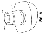
- FIG. 6 is a perspective view, showing the operation of the valve.
- FIG. 7 is a sectional view, showing a version of the valve configured for installation in a fluid line.
- FIG. 8 is a perspective view, showing a version of the valve configured for use as a fuel injector.
- valve assembly 12 truncated cone 14 elastic cylinder 16 retaining groove 18 fluid groove 20 conduit 22 connector 24 female thread 26 inlet cavity 28 fluid manifold 30 annular nozzle 32 in-line variant 34 outlet cavity 36 injector variant
- FIG. 1 shows valve assembly 10 in a disassembled state.
- Truncated cone 12 has a lower end that is larger then its upper end (where “upper” and “lower” are understood in the context of the orientation shown in the view).
- Retaining groove 16 is cut into the lower end, while fluid groove 18 is cut into the truncated cone between retaining groove 16 and the upper end of the truncated cone.
- Connector 22 provides a connection point to a source of fluid which feeds into the valve.
- Elastic cylinder 14 is hollow. It is made of a pliable material, so that it can be slipped over truncated cone 12 , as will be described subsequently.
- FIG. 2 is a sectional view through the valve, with elastic cylinder 14 removed. Fluid flows from inside connector 22 through inlet cavity 26 , fluid manifold 28 , and conduit 20 . Conduit 20 connects fluid manifold 28 to fluid groove 18 .
- FIG. 3 shows a view of valve assembly 10 in an assembled state.
- Elastic cylinder 14 has been placed over truncated cone 12 .
- the inner diameter of elastic cylinder 14 is significantly smaller than the maximum diameter of truncated cone 12 .
- elastic cylinder 14 must deform as shown.
- FIG. 4 is a sectional view through truncated cone 12 and elastic cylinder 14 . The reader will observe that the lower portion of elastic cylinder 14 slips into retaining groove 16 , while the middle portion lays over fluid groove 18 .
- the upper portion of elastic cylinder 14 lies tightly against the upper portion of truncated cone 12 .
- a potential gap exists between the upper portion of elastic cylinder 14 and the upper portion of truncated cone 12 , which is ordinarily sealed. This potential gap is denoted as annular nozzle 30 .
- FIG. 5 another sectional view—shows the operation of the valve.
- the valve opens to admit flow.
- the pressure is transmitted through fluid manifold 28 , conduit 20 , and around fluid groove 18 .
- the shape of the truncated cone dictates that the part of elastic cylinder 14 lying above fluid groove 18 (“above” in the view as shown) is less tightly stretched than the portion lying below fluid groove 18 .
- the fluid travels upward, deflecting that portion of elastic cylinder 14 away from truncated cone 12 .
- Annular nozzle 30 opens and the fluid escapes in the direction indicated by the arrows.
- the reader should note that the deformation of elastic cylinder 14 is exaggerated in the view. The width across the annular nozzle will actually be quite small. In fact, the fluid may escape at two or three main points around the annular nozzle.
- the term “annular nozzle” is intended to describe the shape of the potential gap and not necessarily the shape of the actual fluid flow.
- FIG. 6 shows the same view without the section. Again, the width across annular nozzle 30 is exaggerated for purposes of visual clarity.
- elastic cylinder 14 will be clamped tightly against truncated cone 12 , thereby closing the valve against reverse flow.
- the valve is a one-way “check” type of valve. In looking back at FIG. 4 , those skilled in the art will also realize that no fluid is retained within the valve downstream of the “check” feature (the interface of fluid groove 18 with the interior of elastic cylinder 14 ). This feature allows the valve to be effectively used in many applications, including:
- Spraying operations where exposure of the fluid to air can cause the fluid to solidify, thereby blocking the valve;
- FIG. 7 shows a version of the valve designated as in-line variant 32 . It contains inlet cavity 26 on the “upstream” side and outlet cavity 34 on the “downstream” side. Both cavities have female threads, so that in-line variant 32 can be threaded into a pipeline (Those skilled in the art will know that it may be advisable to use right-hand threads on one end and left-hand threads on the other).
- conduit 20 goes completely through truncated cone 12 and is larger in size. This permits greater flow through the valve.
- One, two, three, or more holes can be used for conduit 20 . Slots or other prior art features can also be substituted.
- the body of the valve can be made from plastic, brass, iron, aluminum, or other known materials.
- the material used for the elastic cylinder depends on the pressure desired across the valve, as well as the fluid used and the expected range of temperatures.
- elastic cylinder 14 can be made of a short piece of vinyl tubing. Numerous other polymers will work. Higher temperature and pressure applications must obviously use different materials.
- FIG. 8 shows one such application.
- the valve assembly shown is used as a diesel fuel injector, designated as injector variant 36 .
- Truncated cone 12 , elastic cylinder 14 , and the internal features are the same as described previously. However, different materials must be used.
- the valve body is typically steel.
- Elastic cylinder 14 must be metal in order to withstand the combustion temperatures. Spring steel is one possible choice for elastic cylinder 14 . In this case, the taper of truncated cone 12 is significantly reduced, since the range of elastic deformation for spring steel is obviously less than for vinyl. It may also be desirable to swage the lower portion of the elastic cylinder into the retaining groove.
- the function of the valve is thereafter identical to the processes described for the plastic and vinyl versions. It opens when the diesel injector pump sends a high-pressure “burst” to the valve, and closes once the burst passes. When the fuel/air mixture ignites within the combustion chamber, the valve closes and prevents any back flow.
Abstract
A one-way valve with an annular nozzle. The valve body is a truncated cone with an interior fluid manifold. The truncated cone section includes a lower retaining groove and a fluid groove. A fluid conduit connects the interior fluid manifold to the fluid groove. An elastic cylinder having an internal diameter which is smaller than the truncated cone is slipped over the truncated cone. The lower portion of the elastic cylinder slips into the retaining groove. The upper portion rests over the fluid groove. When fluid pressure within the interior fluid manifold exceeds the pressure outside the valve, fluid flows through the conduit and into the fluid groove. This pressure urges the upper portion of the elastic cylinder away from the truncated cone Fluid then flows out through an annular nozzle formed between the upper portion of the elastic cylinder and the upper portion of the truncated cone. When pressure outside the valve exceeds the fluid pressure within the interior fluid manifold, the elastic cylinder is clamped tightly against the truncated cone, thereby preventing flow back through the valve.
Description
1. Field of the Invention
This invention relates to the field of fluid control. More specifically, the invention comprises a one-way valve with an annular nozzle.
2. Description of the Related Art
One-way or “check” valves have been in common use for many years. These valves permit fluid flow in one direction while preventing reverse flow. The most common type is a ball and spring valve, where fluid pressure in one direction urges a spring-loaded ball off its seat, thereby permitting flow, while fluid pressure in the opposite direction urges the spring-loaded ball against its seat, thereby preventing flow. Such valves are relatively complex. They require precisely formed seals between the ball and the valve seat. They also tend to trap a small amount of fluid in the valve body, which can lead to additional “dripping” flow after the shut off. The remaining fluid can also contaminate the valve, such as where an air-drying liquid is being fed through the valve.
Reed valves have also been used to create unidirectional flow. These don't tend to trap residual fluids within the valve body. However, they are subject to contamination by small particles, even one of which can cause the valve to remain open when it should be closed. Reed valves, as well as other prior art valve types, are also generally formed of several component parts which must be assembled via rivets, threads, and the like. A simpler valve is obviously desirable.
The present invention comprises a one-way valve with an annular nozzle. The valve body is a truncated cone with an interior fluid manifold. The truncated cone section includes a lower retaining groove and a fluid groove. A fluid conduit connects the interior fluid manifold to the fluid groove. An elastic cylinder having an internal diameter which is smaller than the truncated cone is slipped over the truncated cone. The lower portion of the elastic cylinder slips into the retaining groove. The upper portion rests over the fluid groove. When fluid pressure within the interior fluid manifold exceeds the pressure outside the valve, fluid flows through the conduit and into the fluid groove. This pressure urges the upper portion of the elastic cylinder away from the truncated cone Fluid then flows out through an annular nozzle formed between the upper portion of the elastic cylinder and the upper portion of the truncated cone.
When pressure outside the valve exceeds the fluid pressure within the interior fluid manifold, the elastic cylinder is clamped tightly against the truncated cone, thereby preventing flow back through the valve. In this fashion, flow is only permitted in one direction. Because the valve includes no cavities downstream of the “check” feature, no unwanted fluid is retained within the valve.
| REFERENCE NUMERALS IN THE DRAWINGS |
| 10 | |
12 | truncated |
||
| 14 | |
16 | |
||
| 18 | |
20 | |
||
| 22 | |
24 | |
||
| 26 | |
28 | |
||
| 30 | |
32 | in- |
||
| 34 | |
36 | injector variant | ||
FIG. 5—another sectional view—shows the operation of the valve. When fluid pressure within inlet cavity 26 exceeds the pressure downstream of the valve, the valve opens to admit flow. The pressure is transmitted through fluid manifold 28, conduit 20, and around fluid groove 18. The shape of the truncated cone dictates that the part of elastic cylinder 14 lying above fluid groove 18 (“above” in the view as shown) is less tightly stretched than the portion lying below fluid groove 18. Thus, the fluid travels upward, deflecting that portion of elastic cylinder 14 away from truncated cone 12.
1. Medical valves, where back-flow can contaminate the fluid source with non-sterile agents;
2. Spraying operations, where exposure of the fluid to air can cause the fluid to solidify, thereby blocking the valve;
3. Fuel injection, where residual fuel within the valve tends to build carbon deposits; and
4. Fluid metering operations, where a specific amount of fluid must be added with no subsequent “drip” flow.
The previous illustrations of the valve have not placed it in the context of a larger fluid circuit. Such a circuit is, of course, not particularly important to the invention. However, the reader may wish to know how the valve can be adapted for placement within a fluid circuit. FIG. 7 shows a version of the valve designated as in-line variant 32. It contains inlet cavity 26 on the “upstream” side and outlet cavity 34 on the “downstream” side. Both cavities have female threads, so that in-line variant 32 can be threaded into a pipeline (Those skilled in the art will know that it may be advisable to use right-hand threads on one end and left-hand threads on the other). For the particular version shown, conduit 20 goes completely through truncated cone 12 and is larger in size. This permits greater flow through the valve. One, two, three, or more holes can be used for conduit 20. Slots or other prior art features can also be substituted.
The body of the valve can be made from plastic, brass, iron, aluminum, or other known materials. The material used for the elastic cylinder depends on the pressure desired across the valve, as well as the fluid used and the expected range of temperatures. For water control using a moderate opening pressure, elastic cylinder 14 can be made of a short piece of vinyl tubing. Numerous other polymers will work. Higher temperature and pressure applications must obviously use different materials.
The preceding description contains significant detail regarding the novel aspects of the present invention. It is should not be construed, however, as limiting the scope of the invention but rather as providing illustrations of the preferred embodiments of the invention. Thus, the scope of the invention should be fixed by the following claims, rather than by the examples given.
Claims (11)
1. A fluid control valve, comprising:
a. a truncated cone, having a first end and a second end, wherein said first end is larger than said second end;
b. a retaining groove, proximate said first end of said truncated cone;
c. a fluid groove, between said retaining groove and said second end of said truncated cone; wherein the truncated cone continuously tapers from its second end to its first end, with the exception of the presence of the fluid groove,
d. a fluid manifold inside said truncated cone;
e. a conduit connecting said fluid manifold and said fluid groove; and
f. a hollow elastic cylinder, having a first end and a second end, and being sized to fit tightly over said truncated cone, wherein said first end lies tightly within said retaining groove and wherein said second end lies tightly against said second end of said truncated cone, thereby forming an annular nozzle between said hollow elastic cylinder and said truncated cone.
2. A fluid control valve as recited in claim 1 , further comprising a connector, proximate said first end of said truncated cone, for connecting said fluid control valve to a fluid source.
3. A fluid control valve as recited in claim 2 , further comprising a second connector, proximate said second end of said truncated cone, for connecting said fluid control valve to a fluid circuit.
4. A fluid control valve as recited in claim 1 , wherein said conduit is a hole between said fluid manifold and said fluid groove.
5. A fluid control valve as recited in claim 1 , wherein said conduit is a plurality of holes between said fluid manifold and said fluid groove.
6. A fluid control valve as recited in claim 1 , wherein said elastic cylinder is made from a material capable of withstanding high temperatures.
7. A fluid control valve as recited in claim 1 , wherein said elastic cylinder made from a very elastic material so that it can be manually placed over said truncated cone.
8. A fluid control valve as recited in claim 2 , wherein said connector includes a thread.
9. A fluid control valve as recited in claim 3 , wherein said connector includes a thread and said second connector includes a thread.
10. A fluid control valve as recited in claim 6 , wherein said elastic cylinder is made of spring steel.
11. A fluid control valve as recited in claim 7 , wherein said elastic cylinder is made of vinyl.
Priority Applications (1)
| Application Number | Priority Date | Filing Date | Title |
|---|---|---|---|
| US10/677,580 US7243682B2 (en) | 2003-10-02 | 2003-10-02 | Annular one-way valve |
Applications Claiming Priority (1)
| Application Number | Priority Date | Filing Date | Title |
|---|---|---|---|
| US10/677,580 US7243682B2 (en) | 2003-10-02 | 2003-10-02 | Annular one-way valve |
Publications (2)
| Publication Number | Publication Date |
|---|---|
| US20050072480A1 US20050072480A1 (en) | 2005-04-07 |
| US7243682B2 true US7243682B2 (en) | 2007-07-17 |
Family
ID=34393753
Family Applications (1)
| Application Number | Title | Priority Date | Filing Date |
|---|---|---|---|
| US10/677,580 Expired - Fee Related US7243682B2 (en) | 2003-10-02 | 2003-10-02 | Annular one-way valve |
Country Status (1)
| Country | Link |
|---|---|
| US (1) | US7243682B2 (en) |
Cited By (10)
| Publication number | Priority date | Publication date | Assignee | Title |
|---|---|---|---|---|
| US20060076361A1 (en) * | 2004-09-07 | 2006-04-13 | Clayton Corp. | Anti-crossover dispensing applicator |
| US20100006604A1 (en) * | 2007-02-17 | 2010-01-14 | Yaowu Ding | Lotion pump and one-way valve incorporated therein |
| US20100260892A1 (en) * | 2009-04-08 | 2010-10-14 | Nestec S.A. | Mixing nozzle fitments |
| WO2011049580A1 (en) * | 2009-10-23 | 2011-04-28 | Nestec S.A. | Method and device for aseptically dispensing multiple portions of a fluid |
| EP2383553A1 (en) | 2010-04-30 | 2011-11-02 | Nestec S.A. | Package for storing and dosing a fluid |
| US20120085789A1 (en) * | 2010-10-07 | 2012-04-12 | Fres-Co System Usa, Inc. | Package system including a fitment with anti-flow blocking and shut-off valve for use with dispensing devices |
| US8870025B2 (en) | 2009-10-23 | 2014-10-28 | Nestec S.A. | Method and device for aseptically dispensing multiple portions of a fluid |
| US9867933B2 (en) * | 2010-04-06 | 2018-01-16 | Reseal International Limited Partnership | Delivery system for dispensing metered volumes of pure or sterile flowable substances |
| US20180257841A1 (en) * | 2015-06-11 | 2018-09-13 | Innveri Ag | Device for preserving beverages |
| US10238516B1 (en) * | 2017-11-01 | 2019-03-26 | Barix Medical Corp. | Simplified implantable gastric balloon system with self deflating timer |
Families Citing this family (16)
| Publication number | Priority date | Publication date | Assignee | Title |
|---|---|---|---|---|
| US7331944B2 (en) * | 2000-10-23 | 2008-02-19 | Medical Instill Technologies, Inc. | Ophthalmic dispenser and associated method |
| KR100865601B1 (en) | 2000-10-23 | 2008-10-27 | 피 페턴트, 인크. | Dispenser and method of filling the dispenser |
| US7798185B2 (en) | 2005-08-01 | 2010-09-21 | Medical Instill Technologies, Inc. | Dispenser and method for storing and dispensing sterile food product |
| JP4866005B2 (en) | 2002-08-13 | 2012-02-01 | メディカル・インスティル・テクノロジーズ・インコーポレイテッド | Container for storing and discharging contents and method related thereto |
| US6997219B2 (en) | 2003-05-12 | 2006-02-14 | Medical Instill Technologies, Inc. | Dispenser and apparatus and method for filling a dispenser |
| US7226231B2 (en) | 2003-07-17 | 2007-06-05 | Medical Instill Technologies, Inc. | Piston-type dispenser with one-way valve for storing and dispensing metered amounts of substances |
| JP2008522906A (en) | 2004-12-04 | 2008-07-03 | メディカル・インスティル・テクノロジーズ・インコーポレイテッド | One-way valve and apparatus and method using the valve |
| US7810677B2 (en) * | 2004-12-04 | 2010-10-12 | Medical Instill Technologies, Inc. | One-way valve and apparatus and method of using the valve |
| EP1878210B1 (en) * | 2005-04-29 | 2016-01-13 | Ciena Luxembourg S.a.r.l. | Method and apparatus for non-disruptive call modification |
| RU2480392C2 (en) * | 2006-09-08 | 2013-04-27 | Медикал Инстилл Текнолоджис, Инк. | Device and method for distribution of fluid |
| US8038023B2 (en) * | 2008-05-21 | 2011-10-18 | Sonoco Development, Inc. | Molded container with degassing valve |
| SG185436A1 (en) | 2010-05-07 | 2012-12-28 | Alps Llc | Dispensing machine valve and method |
| JP5484236B2 (en) * | 2010-07-22 | 2014-05-07 | 富士フイルム株式会社 | Endoscopic check valve device |
| KR101740238B1 (en) * | 2012-01-17 | 2017-05-26 | 닥터.피와이 인스터튜트, 엘엘씨 | Device for storing multiple doses of a substance to be diepensed and method for storing and dispensing multiple doses of a substance |
| CN103557358B (en) * | 2013-10-29 | 2017-03-29 | 德施普科技发展温州有限公司 | A kind of discharge valve apparatus |
| US10266382B2 (en) * | 2014-02-18 | 2019-04-23 | The Coca-Cola Company | Beverage nozzle with mixing core |
Citations (16)
| Publication number | Priority date | Publication date | Assignee | Title |
|---|---|---|---|---|
| US384306A (en) * | 1888-06-12 | Francois febnand bouedil | ||
| US2715980A (en) | 1950-10-09 | 1955-08-23 | Leo M Harvey | Liquid handling dispenser |
| US3601151A (en) | 1967-03-29 | 1971-08-24 | Latex Products Proprietary Ltd | Nonreturn valves for medical uses |
| US3739952A (en) | 1971-07-09 | 1973-06-19 | Gillette Co | Intermittent dispensing device |
| US4250844A (en) * | 1979-04-05 | 1981-02-17 | Tews Jan H | Two-cycle engine and piston |
| US4300593A (en) * | 1980-01-04 | 1981-11-17 | Ritter Robert A | Back pressure regulator and non-return valve |
| US4346704A (en) | 1980-09-09 | 1982-08-31 | Baxter Travenol Laboratories, Inc. | Sleeve valve for parenteral solution device |
| US4846810A (en) | 1987-07-13 | 1989-07-11 | Reseal International Limited Partnership | Valve assembly |
| US4919167A (en) | 1989-03-17 | 1990-04-24 | Manska Wayne E | Check valve |
| US5092855A (en) | 1990-01-22 | 1992-03-03 | Reseal International Limited Partnership | Enclosing sleeve for one-way valve |
| USRE34243E (en) | 1987-07-13 | 1993-05-04 | Reseal International Limited Partnership | Valve assembly |
| US5265415A (en) * | 1993-01-27 | 1993-11-30 | The United States Of America As Represented By The Administrator Of The National Aeronautics And Space Administration | Liquid fuel injection elements for rocket engines |
| US5660205A (en) | 1994-12-15 | 1997-08-26 | Epstein; Alan B. | One-way valve |
| US5836484A (en) | 1996-10-03 | 1998-11-17 | Gerber; Bernard R. | Contamination-safe multiple-dose dispensing cartridge for flowable materials |
| US6325253B1 (en) | 2001-02-02 | 2001-12-04 | Owens-Illinois Closure Inc. | Self-closing fluid dispensing closure |
| US6848471B2 (en) * | 2002-09-09 | 2005-02-01 | Hercules Valve Inc. | In-line check valve |
-
2003
- 2003-10-02 US US10/677,580 patent/US7243682B2/en not_active Expired - Fee Related
Patent Citations (16)
| Publication number | Priority date | Publication date | Assignee | Title |
|---|---|---|---|---|
| US384306A (en) * | 1888-06-12 | Francois febnand bouedil | ||
| US2715980A (en) | 1950-10-09 | 1955-08-23 | Leo M Harvey | Liquid handling dispenser |
| US3601151A (en) | 1967-03-29 | 1971-08-24 | Latex Products Proprietary Ltd | Nonreturn valves for medical uses |
| US3739952A (en) | 1971-07-09 | 1973-06-19 | Gillette Co | Intermittent dispensing device |
| US4250844A (en) * | 1979-04-05 | 1981-02-17 | Tews Jan H | Two-cycle engine and piston |
| US4300593A (en) * | 1980-01-04 | 1981-11-17 | Ritter Robert A | Back pressure regulator and non-return valve |
| US4346704A (en) | 1980-09-09 | 1982-08-31 | Baxter Travenol Laboratories, Inc. | Sleeve valve for parenteral solution device |
| USRE34243E (en) | 1987-07-13 | 1993-05-04 | Reseal International Limited Partnership | Valve assembly |
| US4846810A (en) | 1987-07-13 | 1989-07-11 | Reseal International Limited Partnership | Valve assembly |
| US4919167A (en) | 1989-03-17 | 1990-04-24 | Manska Wayne E | Check valve |
| US5092855A (en) | 1990-01-22 | 1992-03-03 | Reseal International Limited Partnership | Enclosing sleeve for one-way valve |
| US5265415A (en) * | 1993-01-27 | 1993-11-30 | The United States Of America As Represented By The Administrator Of The National Aeronautics And Space Administration | Liquid fuel injection elements for rocket engines |
| US5660205A (en) | 1994-12-15 | 1997-08-26 | Epstein; Alan B. | One-way valve |
| US5836484A (en) | 1996-10-03 | 1998-11-17 | Gerber; Bernard R. | Contamination-safe multiple-dose dispensing cartridge for flowable materials |
| US6325253B1 (en) | 2001-02-02 | 2001-12-04 | Owens-Illinois Closure Inc. | Self-closing fluid dispensing closure |
| US6848471B2 (en) * | 2002-09-09 | 2005-02-01 | Hercules Valve Inc. | In-line check valve |
Cited By (21)
| Publication number | Priority date | Publication date | Assignee | Title |
|---|---|---|---|---|
| US7559440B2 (en) * | 2004-09-07 | 2009-07-14 | Clayton Corporation | Anti-crossover dispensing applicator |
| US20060076361A1 (en) * | 2004-09-07 | 2006-04-13 | Clayton Corp. | Anti-crossover dispensing applicator |
| US20100006604A1 (en) * | 2007-02-17 | 2010-01-14 | Yaowu Ding | Lotion pump and one-way valve incorporated therein |
| US8231031B2 (en) * | 2007-02-17 | 2012-07-31 | Yaowu Ding | Lotion pump and one-way valve incorporated therein |
| US8591099B2 (en) | 2009-04-08 | 2013-11-26 | Nestec S.A. | Mixing nozzle fitments |
| US20100260892A1 (en) * | 2009-04-08 | 2010-10-14 | Nestec S.A. | Mixing nozzle fitments |
| US9409757B2 (en) | 2009-04-08 | 2016-08-09 | Nestec S.A. | Mixing nozzle fitments |
| US9278843B2 (en) | 2009-04-08 | 2016-03-08 | Nestec S.A. | Mixing nozzle fitments |
| US9145289B2 (en) | 2009-04-08 | 2015-09-29 | Nestec S.A. | Mixing nozzle fitment and mixed liquid dispenser |
| RU2508245C2 (en) * | 2009-10-23 | 2014-02-27 | Нестек С.А. | Method and device for aseptic feed of great amount of fluid portions |
| US8870025B2 (en) | 2009-10-23 | 2014-10-28 | Nestec S.A. | Method and device for aseptically dispensing multiple portions of a fluid |
| AU2009354185B2 (en) * | 2009-10-23 | 2015-03-05 | Nestec S.A. | Method and device for aseptically dispensing multiple portions of a fluid |
| US9242786B2 (en) | 2009-10-23 | 2016-01-26 | Nestec S.A. | Method and device for aseptically dispensing multiple portions of a fluid |
| WO2011049580A1 (en) * | 2009-10-23 | 2011-04-28 | Nestec S.A. | Method and device for aseptically dispensing multiple portions of a fluid |
| US9867933B2 (en) * | 2010-04-06 | 2018-01-16 | Reseal International Limited Partnership | Delivery system for dispensing metered volumes of pure or sterile flowable substances |
| WO2011134858A2 (en) | 2010-04-30 | 2011-11-03 | Nestec S.A. | Package for storing and dosing a fluid and dispenser for docking the package |
| EP2383553A1 (en) | 2010-04-30 | 2011-11-02 | Nestec S.A. | Package for storing and dosing a fluid |
| US20120085789A1 (en) * | 2010-10-07 | 2012-04-12 | Fres-Co System Usa, Inc. | Package system including a fitment with anti-flow blocking and shut-off valve for use with dispensing devices |
| US20180257841A1 (en) * | 2015-06-11 | 2018-09-13 | Innveri Ag | Device for preserving beverages |
| US10625919B2 (en) * | 2015-06-11 | 2020-04-21 | Innveri Ag | Device for preserving beverages |
| US10238516B1 (en) * | 2017-11-01 | 2019-03-26 | Barix Medical Corp. | Simplified implantable gastric balloon system with self deflating timer |
Also Published As
| Publication number | Publication date |
|---|---|
| US20050072480A1 (en) | 2005-04-07 |
Similar Documents
| Publication | Publication Date | Title |
|---|---|---|
| US7243682B2 (en) | Annular one-way valve | |
| DE602005004990T2 (en) | Flow component for medical infusion / transfusion lines | |
| US3943969A (en) | Positive acting check valve of polyvinylchloride to open in response to predetermined line pressure | |
| EP1129740B1 (en) | Infusion rate adjusting device for drug solution injector | |
| DE102017212726B3 (en) | Jet pump unit for controlling a gaseous medium | |
| US6446652B1 (en) | Backflow preventer assembly | |
| US11654452B2 (en) | Apparatuses and methods using high pressure dual check valve | |
| MX2007003864A (en) | Dome check valve. | |
| JPH08312863A (en) | Piping connection device | |
| GB2569453A (en) | In-line fluid pressure regulator | |
| CN110005932A (en) | With the lubricant injector for improving piston | |
| CN104081039B (en) | For the Fuelinjection nozzle of internal combustion engine | |
| US6168400B1 (en) | Check valve module | |
| US20060018770A1 (en) | Valve | |
| GB2369407A (en) | Valve for controlling liquids, with a central leakage drain | |
| DE10041555A1 (en) | Degassing device used for degassing liquefied gas lines and pumps comprises degassing valve for degassing fluid conveying line in gas outlet, and moving valve body pre-tensioned by pre-tensioned element | |
| CA2478584A1 (en) | Valve for fluid filter | |
| DE20314499U1 (en) | Check valve for vacuum pumps | |
| US20180347715A1 (en) | Pressure-balancing valve | |
| US3456915A (en) | Valve seats for high pressure valves | |
| US20090229675A1 (en) | In-line filter/flow regulator/anti-siphon device | |
| DE102008056109A1 (en) | Valve with a device against water hammer | |
| JP2011021652A (en) | Liquid drip preventing check valve | |
| WO2014072678A2 (en) | A pump assembly and a valve | |
| JP2003033679A (en) | Stopper apparatus |
Legal Events
| Date | Code | Title | Description |
|---|---|---|---|
| FPAY | Fee payment |
Year of fee payment: 4 |
|
| REMI | Maintenance fee reminder mailed | ||
| LAPS | Lapse for failure to pay maintenance fees | ||
| STCH | Information on status: patent discontinuation |
Free format text: PATENT EXPIRED DUE TO NONPAYMENT OF MAINTENANCE FEES UNDER 37 CFR 1.362 |
|
| FP | Lapsed due to failure to pay maintenance fee |
Effective date: 20150717 |