US7214232B2 - Graft fixation device - Google Patents
Graft fixation device Download PDFInfo
- Publication number
- US7214232B2 US7214232B2 US10/142,399 US14239902A US7214232B2 US 7214232 B2 US7214232 B2 US 7214232B2 US 14239902 A US14239902 A US 14239902A US 7214232 B2 US7214232 B2 US 7214232B2
- Authority
- US
- United States
- Prior art keywords
- members
- implantation
- bone
- seen
- matrix
- Prior art date
- Legal status (The legal status is an assumption and is not a legal conclusion. Google has not performed a legal analysis and makes no representation as to the accuracy of the status listed.)
- Expired - Lifetime
Links
Images


Classifications
-
- A—HUMAN NECESSITIES
- A61—MEDICAL OR VETERINARY SCIENCE; HYGIENE
- A61B—DIAGNOSIS; SURGERY; IDENTIFICATION
- A61B17/00—Surgical instruments, devices or methods, e.g. tourniquets
- A61B17/04—Surgical instruments, devices or methods, e.g. tourniquets for suturing wounds; Holders or packages for needles or suture materials
- A61B17/0401—Suture anchors, buttons or pledgets, i.e. means for attaching sutures to bone, cartilage or soft tissue; Instruments for applying or removing suture anchors
-
- A—HUMAN NECESSITIES
- A61—MEDICAL OR VETERINARY SCIENCE; HYGIENE
- A61B—DIAGNOSIS; SURGERY; IDENTIFICATION
- A61B17/00—Surgical instruments, devices or methods, e.g. tourniquets
- A61B17/064—Surgical staples, i.e. penetrating the tissue
- A61B17/0642—Surgical staples, i.e. penetrating the tissue for bones, e.g. for osteosynthesis or connecting tendon to bone
-
- A—HUMAN NECESSITIES
- A61—MEDICAL OR VETERINARY SCIENCE; HYGIENE
- A61B—DIAGNOSIS; SURGERY; IDENTIFICATION
- A61B17/00—Surgical instruments, devices or methods, e.g. tourniquets
- A61B17/068—Surgical staplers, e.g. containing multiple staples or clamps
-
- A—HUMAN NECESSITIES
- A61—MEDICAL OR VETERINARY SCIENCE; HYGIENE
- A61B—DIAGNOSIS; SURGERY; IDENTIFICATION
- A61B17/00—Surgical instruments, devices or methods, e.g. tourniquets
- A61B17/00234—Surgical instruments, devices or methods, e.g. tourniquets for minimally invasive surgery
-
- A—HUMAN NECESSITIES
- A61—MEDICAL OR VETERINARY SCIENCE; HYGIENE
- A61B—DIAGNOSIS; SURGERY; IDENTIFICATION
- A61B17/00—Surgical instruments, devices or methods, e.g. tourniquets
- A61B17/04—Surgical instruments, devices or methods, e.g. tourniquets for suturing wounds; Holders or packages for needles or suture materials
- A61B17/06—Needles ; Sutures; Needle-suture combinations; Holders or packages for needles or suture materials
-
- A—HUMAN NECESSITIES
- A61—MEDICAL OR VETERINARY SCIENCE; HYGIENE
- A61B—DIAGNOSIS; SURGERY; IDENTIFICATION
- A61B17/00—Surgical instruments, devices or methods, e.g. tourniquets
- A61B17/064—Surgical staples, i.e. penetrating the tissue
-
- A—HUMAN NECESSITIES
- A61—MEDICAL OR VETERINARY SCIENCE; HYGIENE
- A61B—DIAGNOSIS; SURGERY; IDENTIFICATION
- A61B17/00—Surgical instruments, devices or methods, e.g. tourniquets
- A61B17/56—Surgical instruments or methods for treatment of bones or joints; Devices specially adapted therefor
- A61B17/58—Surgical instruments or methods for treatment of bones or joints; Devices specially adapted therefor for osteosynthesis, e.g. bone plates, screws, setting implements or the like
- A61B17/88—Osteosynthesis instruments; Methods or means for implanting or extracting internal or external fixation devices
- A61B17/92—Impactors or extractors, e.g. for removing intramedullary devices
-
- A—HUMAN NECESSITIES
- A61—MEDICAL OR VETERINARY SCIENCE; HYGIENE
- A61B—DIAGNOSIS; SURGERY; IDENTIFICATION
- A61B17/00—Surgical instruments, devices or methods, e.g. tourniquets
- A61B2017/00004—(bio)absorbable, (bio)resorbable, resorptive
-
- A—HUMAN NECESSITIES
- A61—MEDICAL OR VETERINARY SCIENCE; HYGIENE
- A61B—DIAGNOSIS; SURGERY; IDENTIFICATION
- A61B17/00—Surgical instruments, devices or methods, e.g. tourniquets
- A61B17/00234—Surgical instruments, devices or methods, e.g. tourniquets for minimally invasive surgery
- A61B2017/00238—Type of minimally invasive operation
- A61B2017/00243—Type of minimally invasive operation cardiac
-
- A—HUMAN NECESSITIES
- A61—MEDICAL OR VETERINARY SCIENCE; HYGIENE
- A61B—DIAGNOSIS; SURGERY; IDENTIFICATION
- A61B17/00—Surgical instruments, devices or methods, e.g. tourniquets
- A61B2017/00743—Type of operation; Specification of treatment sites
- A61B2017/00778—Operations on blood vessels
- A61B2017/00783—Valvuloplasty
-
- A—HUMAN NECESSITIES
- A61—MEDICAL OR VETERINARY SCIENCE; HYGIENE
- A61B—DIAGNOSIS; SURGERY; IDENTIFICATION
- A61B17/00—Surgical instruments, devices or methods, e.g. tourniquets
- A61B17/04—Surgical instruments, devices or methods, e.g. tourniquets for suturing wounds; Holders or packages for needles or suture materials
- A61B17/0401—Suture anchors, buttons or pledgets, i.e. means for attaching sutures to bone, cartilage or soft tissue; Instruments for applying or removing suture anchors
- A61B2017/0406—Pledgets
-
- A—HUMAN NECESSITIES
- A61—MEDICAL OR VETERINARY SCIENCE; HYGIENE
- A61B—DIAGNOSIS; SURGERY; IDENTIFICATION
- A61B17/00—Surgical instruments, devices or methods, e.g. tourniquets
- A61B17/04—Surgical instruments, devices or methods, e.g. tourniquets for suturing wounds; Holders or packages for needles or suture materials
- A61B17/0401—Suture anchors, buttons or pledgets, i.e. means for attaching sutures to bone, cartilage or soft tissue; Instruments for applying or removing suture anchors
- A61B2017/0409—Instruments for applying suture anchors
-
- A—HUMAN NECESSITIES
- A61—MEDICAL OR VETERINARY SCIENCE; HYGIENE
- A61B—DIAGNOSIS; SURGERY; IDENTIFICATION
- A61B17/00—Surgical instruments, devices or methods, e.g. tourniquets
- A61B17/04—Surgical instruments, devices or methods, e.g. tourniquets for suturing wounds; Holders or packages for needles or suture materials
- A61B17/0401—Suture anchors, buttons or pledgets, i.e. means for attaching sutures to bone, cartilage or soft tissue; Instruments for applying or removing suture anchors
- A61B2017/0412—Suture anchors, buttons or pledgets, i.e. means for attaching sutures to bone, cartilage or soft tissue; Instruments for applying or removing suture anchors having anchoring barbs or pins extending outwardly from suture anchor body
-
- A—HUMAN NECESSITIES
- A61—MEDICAL OR VETERINARY SCIENCE; HYGIENE
- A61B—DIAGNOSIS; SURGERY; IDENTIFICATION
- A61B17/00—Surgical instruments, devices or methods, e.g. tourniquets
- A61B17/04—Surgical instruments, devices or methods, e.g. tourniquets for suturing wounds; Holders or packages for needles or suture materials
- A61B17/0401—Suture anchors, buttons or pledgets, i.e. means for attaching sutures to bone, cartilage or soft tissue; Instruments for applying or removing suture anchors
- A61B2017/0414—Suture anchors, buttons or pledgets, i.e. means for attaching sutures to bone, cartilage or soft tissue; Instruments for applying or removing suture anchors having a suture-receiving opening, e.g. lateral opening
-
- A—HUMAN NECESSITIES
- A61—MEDICAL OR VETERINARY SCIENCE; HYGIENE
- A61B—DIAGNOSIS; SURGERY; IDENTIFICATION
- A61B17/00—Surgical instruments, devices or methods, e.g. tourniquets
- A61B17/04—Surgical instruments, devices or methods, e.g. tourniquets for suturing wounds; Holders or packages for needles or suture materials
- A61B17/0401—Suture anchors, buttons or pledgets, i.e. means for attaching sutures to bone, cartilage or soft tissue; Instruments for applying or removing suture anchors
- A61B2017/0419—H-fasteners
-
- A—HUMAN NECESSITIES
- A61—MEDICAL OR VETERINARY SCIENCE; HYGIENE
- A61B—DIAGNOSIS; SURGERY; IDENTIFICATION
- A61B17/00—Surgical instruments, devices or methods, e.g. tourniquets
- A61B17/04—Surgical instruments, devices or methods, e.g. tourniquets for suturing wounds; Holders or packages for needles or suture materials
- A61B17/0401—Suture anchors, buttons or pledgets, i.e. means for attaching sutures to bone, cartilage or soft tissue; Instruments for applying or removing suture anchors
- A61B2017/0427—Suture anchors, buttons or pledgets, i.e. means for attaching sutures to bone, cartilage or soft tissue; Instruments for applying or removing suture anchors having anchoring barbs or pins extending outwardly from the anchor body
-
- A—HUMAN NECESSITIES
- A61—MEDICAL OR VETERINARY SCIENCE; HYGIENE
- A61B—DIAGNOSIS; SURGERY; IDENTIFICATION
- A61B17/00—Surgical instruments, devices or methods, e.g. tourniquets
- A61B17/04—Surgical instruments, devices or methods, e.g. tourniquets for suturing wounds; Holders or packages for needles or suture materials
- A61B17/0401—Suture anchors, buttons or pledgets, i.e. means for attaching sutures to bone, cartilage or soft tissue; Instruments for applying or removing suture anchors
- A61B2017/0445—Suture anchors, buttons or pledgets, i.e. means for attaching sutures to bone, cartilage or soft tissue; Instruments for applying or removing suture anchors cannulated, e.g. with a longitudinal through-hole for passage of an instrument
-
- A—HUMAN NECESSITIES
- A61—MEDICAL OR VETERINARY SCIENCE; HYGIENE
- A61B—DIAGNOSIS; SURGERY; IDENTIFICATION
- A61B17/00—Surgical instruments, devices or methods, e.g. tourniquets
- A61B17/04—Surgical instruments, devices or methods, e.g. tourniquets for suturing wounds; Holders or packages for needles or suture materials
- A61B17/06—Needles ; Sutures; Needle-suture combinations; Holders or packages for needles or suture materials
- A61B2017/06057—Double-armed sutures, i.e. sutures having a needle attached to each end
-
- A—HUMAN NECESSITIES
- A61—MEDICAL OR VETERINARY SCIENCE; HYGIENE
- A61B—DIAGNOSIS; SURGERY; IDENTIFICATION
- A61B17/00—Surgical instruments, devices or methods, e.g. tourniquets
- A61B17/04—Surgical instruments, devices or methods, e.g. tourniquets for suturing wounds; Holders or packages for needles or suture materials
- A61B17/06—Needles ; Sutures; Needle-suture combinations; Holders or packages for needles or suture materials
- A61B17/06066—Needles, e.g. needle tip configurations
- A61B2017/0608—J-shaped
-
- A—HUMAN NECESSITIES
- A61—MEDICAL OR VETERINARY SCIENCE; HYGIENE
- A61B—DIAGNOSIS; SURGERY; IDENTIFICATION
- A61B17/00—Surgical instruments, devices or methods, e.g. tourniquets
- A61B17/064—Surgical staples, i.e. penetrating the tissue
- A61B2017/0646—Surgical staples, i.e. penetrating the tissue for insertion into cartillege, e.g. meniscus
-
- A—HUMAN NECESSITIES
- A61—MEDICAL OR VETERINARY SCIENCE; HYGIENE
- A61B—DIAGNOSIS; SURGERY; IDENTIFICATION
- A61B17/00—Surgical instruments, devices or methods, e.g. tourniquets
- A61B17/064—Surgical staples, i.e. penetrating the tissue
- A61B2017/0647—Surgical staples, i.e. penetrating the tissue having one single leg, e.g. tacks
-
- A—HUMAN NECESSITIES
- A61—MEDICAL OR VETERINARY SCIENCE; HYGIENE
- A61F—FILTERS IMPLANTABLE INTO BLOOD VESSELS; PROSTHESES; DEVICES PROVIDING PATENCY TO, OR PREVENTING COLLAPSING OF, TUBULAR STRUCTURES OF THE BODY, e.g. STENTS; ORTHOPAEDIC, NURSING OR CONTRACEPTIVE DEVICES; FOMENTATION; TREATMENT OR PROTECTION OF EYES OR EARS; BANDAGES, DRESSINGS OR ABSORBENT PADS; FIRST-AID KITS
- A61F2/00—Filters implantable into blood vessels; Prostheses, i.e. artificial substitutes or replacements for parts of the body; Appliances for connecting them with the body; Devices providing patency to, or preventing collapsing of, tubular structures of the body, e.g. stents
- A61F2/0063—Implantable repair or support meshes, e.g. hernia meshes
-
- A—HUMAN NECESSITIES
- A61—MEDICAL OR VETERINARY SCIENCE; HYGIENE
- A61F—FILTERS IMPLANTABLE INTO BLOOD VESSELS; PROSTHESES; DEVICES PROVIDING PATENCY TO, OR PREVENTING COLLAPSING OF, TUBULAR STRUCTURES OF THE BODY, e.g. STENTS; ORTHOPAEDIC, NURSING OR CONTRACEPTIVE DEVICES; FOMENTATION; TREATMENT OR PROTECTION OF EYES OR EARS; BANDAGES, DRESSINGS OR ABSORBENT PADS; FIRST-AID KITS
- A61F2/00—Filters implantable into blood vessels; Prostheses, i.e. artificial substitutes or replacements for parts of the body; Appliances for connecting them with the body; Devices providing patency to, or preventing collapsing of, tubular structures of the body, e.g. stents
- A61F2/02—Prostheses implantable into the body
- A61F2/08—Muscles; Tendons; Ligaments
- A61F2/0811—Fixation devices for tendons or ligaments
-
- A—HUMAN NECESSITIES
- A61—MEDICAL OR VETERINARY SCIENCE; HYGIENE
- A61F—FILTERS IMPLANTABLE INTO BLOOD VESSELS; PROSTHESES; DEVICES PROVIDING PATENCY TO, OR PREVENTING COLLAPSING OF, TUBULAR STRUCTURES OF THE BODY, e.g. STENTS; ORTHOPAEDIC, NURSING OR CONTRACEPTIVE DEVICES; FOMENTATION; TREATMENT OR PROTECTION OF EYES OR EARS; BANDAGES, DRESSINGS OR ABSORBENT PADS; FIRST-AID KITS
- A61F2/00—Filters implantable into blood vessels; Prostheses, i.e. artificial substitutes or replacements for parts of the body; Appliances for connecting them with the body; Devices providing patency to, or preventing collapsing of, tubular structures of the body, e.g. stents
- A61F2/02—Prostheses implantable into the body
- A61F2/28—Bones
- A61F2/2846—Support means for bone substitute or for bone graft implants, e.g. membranes or plates for covering bone defects
Definitions
- the field of art to which this invention relates is surgical fastening devices, in particular, surgical fastening devices for fixating tissue grafts to bone.
- tissue engineering has advanced at a rapid pace.
- cells from the human body for example, chondrocytes and fibrochrondrocytes from the knee joint.
- These autologous cells are then cultured in a laboratory environment on a bioabsorbable matrix.
- the matrix will typically have a shape substantially similar to the tissue section which needs to be replaced.
- the harvested cells will grow on the matrix to form an implantable section of tissue having substantially the same physical configuration as the section of tissue which needs to be replaced in the patient.
- tissue-engineered construct consisting of cells on the matrix (or, alternatively, consisting of a matrix alone without cells) is then affixed to the bone site using conventionally known surgical fasteners including sutures, periosteal coverings, or fibrin glue.
- tissue engineering are many, not the least of which is, for example, that it is now possible to replace cartilage with living cartilage tissue.
- the likelihood of rejection of the tissue implant is minimized since the cartilage tissue which has been grown in-vitro is identical to the autologous cartilage of the patient.
- the graft fixation device has first and second implantation members.
- the members are elongated and preferably have a cylindrical configuration.
- the members also have distal ends, proximal ends, and longitudinal axes. There are longitudinal passages extending through the entire length of each implantation member.
- the members have outer surfaces.
- the implantation members are connected to each other by a rod member having first and second ends and a central section. The first end of the rod member extends from the proximal end of the first implantation member and the second end of the rod member extends from the proximal end of the second implantation member.
- the rod member is preferably relatively rigid and may be configured to have a variety of geometric shapes, for example, an inverted “U” shape.
- the rod member may also be flexible.
- the rod member maintains the implantation members at a relatively fixed distance from each other.
- the central section of the rod member is designed to engage a section of a tissue-engineered matrix implant.
- the implantation members have a series of ridges extending out from the outer surfaces of the implantation members to assist in preventing withdrawal from a bone site or other anchoring site after the implantation members are implanted into previously-created bore holes.
- Yet another aspect of the present invention is a method of using the graft fixation device of the present invention to affix a matrix containing tissue-engineered tissue to a bone.
- Still yet another aspect of the present invention is a graft fixation device combination which is the combination of a fixation device and an insertion device.
- the fixation device has a first implantation member.
- the implantation member has a longitudinal axis, a proximal end, a distal end, an outer surface, and a longitudinal passage therethrough.
- the fixation device also has a second implantation member.
- the second implantation member has a longitudinal axis, a proximal end, a distal end, an outer surface, and a longitudinal passage therethrough.
- Each implantation member has a proximal annular face on its proximal end surrounding the longitudinal passages.
- the connecting member has a central section, a first end extending from the first implantation member and a second end extending from the second implantation member.
- Each insertion device is a member having a proximal end, a distal tapered end and a longitudinal passage therethrough. The distal end of each implantation member is in engagement with the proximal end of an insertion device.
- an insertion device is mounted to the distal end of an implantation member.
- the graft fixation device has first and second implantation members.
- the members are elongated and preferably have a cylindrical configuration.
- the members also have distal ends, proximal ends, and longitudinal axes.
- the members have outer surfaces.
- the implantation members are connected to each other by a rod member having first and second ends and a central section. The first end of the rod member extends from the proximal end of the first implantation member and the second end of the rod member extends from the proximal end of the second implantation member.
- the rod member is preferably relatively rigid and may be configured to have a variety of geometric shapes, for example, an inverted “U” shape. However, the rod member may also be flexible. The rod member maintains the b The wing member facilitates such engagement.
- the implantation members have a series of ridges extending out from the outer surfaces of the implantation members to assist in preventing withdrawal from a bone site or other anchoring site after the implantation members are implanted into previously-created bore holes.
- Yet another aspect of the present invention is a method of using the above-described graft fixation device having a laterally extending wing member to affix a matrix containing tissue-engineered tissue to a bone.
- a further aspect of the present invention is a graft fixation device combination which is the combination of a fixation device and an insertion device.
- the fixation device has a first implantation member.
- the implantation member has a longitudinal axis, a proximal end, a distal end, an outer surface, and a longitudinal passage therethrough.
- the fixation device also has a second implantation member.
- the second implantation member has a longitudinal axis, a proximal end, a distal end, an outer surface, and a longitudinal passage therethrough.
- Each implantation member has a proximal annular face on its proximal end surrounding the longitudinal passages.
- the connecting rod member has a central section, a first end extending from the first implantation member and a second end extending from the second implantation member. Extending laterally outward from the connecting member is at least one wing member. There are a pair of insertion devices. Each insertion device is a member having a proximal end, a distal tapered end and a longitudinal passage therethrough. The distal end of each implantation member is in engagement with the proximal end of an insertion device. Optionally an insertion device is mounted to the distal end of an implantation member.
- Yet another aspect of the present invention is a method of using the above-described graft fixation device combination having a laterally extending wing member to affix a matrix containing tissue-engineered tissue to a bone.
- a further aspect of the present invention is a graft fixation device.
- the graft fixation device has a first implantation member and a second implantation member.
- Each implantation member has an outer surface, a longitudinal axis, a proximal end and a distal end. Extending from, or mounted to, the distal end of each implantation member is a penetrating insertion member.
- the implantation members have a longitudinal passage, and proximal and distal openings in communication with the passage.
- the insertion members have outer surfaces, proximal ends, distal ends, and longitudinal axes.
- Each insertion member has a longitudinal passage and a proximal opening.
- the longitudinal passage has a distal closed, blind end.
- each insertion member is in communication with the distal opening of the implantation member and the longitudinal passage of the insertion member.
- the implantation members are connected to each other by a retention member having first and second ends and a central section.
- the first end of the retention member extends from the proximal end of the first implantation member and the second end of the retention member extends from the proximal end of the second implantation member.
- the retention member is preferably relatively rigid, and may be configured to have a variety of geometric shapes, for example, an inverted “U” shape. However, the retention member may also be flexible.
- extending laterally outward from the retention member is at least one wing member.
- the central section of the retention member with the optional wing member may engage a section of an implant such as a tissue-engineered matrix implant.
- Yet another aspect of the present invention is a method of using the above-described graft fixation device to affix a matrix to a bone, e.g., to mount a matrix to a bone.
- Still yet a further aspect of the present invention is a novel instrument which can be used in a surgical procedure to insert the above-described graft fixation device in bone.
- FIG. 1 is a perspective view of a graft fixation device of the present invention.
- FIG. 2 is a cross-sectional view of the graft fixation device of FIG. 1 taken along view line 2 — 2 .
- FIGS. 3-6 illustrate a surgical procedure for affixing a matrix to bone using the graft fixation device of the present invention.
- FIG. 7 is an illustration of a graft fixation device of the present invention after the implantation members have been implanted in bore holes in bone illustrating the device affixing a matrix securely to the surface of a bone.
- FIG. 8 is a cross-sectional view of the graft fixation device of FIG. 7 implanted in bone, and taken along View Line 8 — 8 .
- FIG. 9 is an alternative embodiment of a graft fixation device of the present invention having two connecting members.
- FIG. 10 is a perspective view of an instrument useful for making bore holes in bone into which the implantable members of the graft fixation devices of the present invention may be emplaced.
- FIG. 11 is a perspective view of an instrument useful for implanting the device of the present invention into bore holes made in bone.
- FIG. 12 is a view of a tissue engineered matrix secured to a bone with several graft fixation devices of the present invention.
- FIG. 13 is a perspective view of an alternate embodiment of a graft fixation device of the present invention.
- FIG. 14 is a side view of the graft fixation device of FIG. 13 .
- FIG. 15 is an end view of the graft fixation device of FIG. 14 .
- FIG. 16 is a cross-sectional view of the graft fixation device of FIG. 14 , taken along View-Line 16 — 16 .
- FIG. 17 is a cross-sectional view of the tissue retention member of the graft fixation device of FIG. 14 , taken along View-Line 17 — 17 .
- FIG. 18 is a perspective view of an insertion member useful to insert a graft fixation member of the present invention.
- FIG. 19 is an exploded perspective view of an insertion instrument, a graft fixation device, and two insertion members.
- FIG. 20 is a side view of the distal end of the insertion instrument, a graft fixation device, and insertion members engaged in bone, prior to removal of the insertion device.
- FIG. 21 is a cross-sectional view taken along View-Line 21 — 21 of FIG. 20 of the prong of the insertion instrument, and a section of the retention member engaged in a longitudinal groove of the prong.
- FIG. 22 is an exploded perspective view of the distal end of an insertion instrument of the present invention, illustrating a removable distal end assembly for creating bore holes in bone for receiving the fixation devices of the present invention, wherein the assembly has an end member and pins.
- FIG. 23 is a cross-section of the assembly end member of FIG. 22 , taken along View-Line 23 .
- FIG. 24 is a perspective view of the assembly end of FIG. 22 , completely assembled and ready for use.
- FIG. 25 is a cross-sectional view of the end assembly of FIG. 24 , taken along View-Line 25 — 25 .
- FIG. 26 is an exploded perspective view of an insertion instrument of the present invention having a removable distal end assembly useful for inserting the graft retention members of the present invention into bore holes in a bone, having an end assembly member and two pins; when used with insertion members, the instrument can be used to emplace the fixation devices directly into bone without first forming bone bore holes.
- FIG. 27 is a cross-sectional view of the end assembly member of FIG. 26 .
- FIG. 28 is a perspective view of the distal end of the insertion instrument of FIG. 26 , having the end assembly member and prongs fully assembled and mounted.
- FIG. 29 is a cross-sectional view of the distal end of the insertion instrument of FIG. 28 take along View-Line 29 — 29 .
- FIG. 30 is a cross-sectional view of the instrument of FIG. 29 taken along View-Line 30 — 30 .
- FIG. 31 illustrates a fixation device of the present member having an insertion member molded into the distal end of each implantation member.
- FIG. 32 is a cross-sectional view of the fixation device of FIG. 31 .
- FIG. 33 is a perspective view of an alternate embodiment of a graft fixation device of the present invention having laterally extending wing members.
- FIG. 34 is a view of a matrix secured to a bone with several graft fixation members of FIG. 33 .
- FIG. 35 is a perspective view of yet another alternate embodiment of a graft fixation device of the present invention having laterally extending wing members.
- FIG. 36 is a view of a matrix secured to a bone with several graft fixation members of FIG. 35 .
- FIG. 37 is a perspective view of an alternate embodiment of a graft fixation device of the present invention.
- the implantation member has a longitudinal passage that extends partially therethrough.
- FIG. 38 is a cross-sectional view of the graft fixation device of FIG. 37 taken along View-Line 38 — 38 , also illustrating the mounting prongs of the insertion instrument.
- FIG. 39 is a top view of a matrix secured to a bone with several of the graft fixation members of FIG. 37 .
- FIG. 40 is a cross-sectional view of the retention member of the fastener of FIG. 37 taken along View-Line 40 — 40 .
- FIG. 41 is a cross-sectional view of the retention member of the fastener of FIG. 37 taken along View-Line 41 — 41 .
- FIG. 42 is an exploded perspective view of an insertion instrument useful to apply the fasteners of FIG. 37 .
- FIG. 42A is a partial magnified perspective view of the distal end of the shaft of the instrument of FIG. 42 illustrating the mounting prongs.
- FIG. 43 is a perspective view of the instrument of FIG. 43 mounted to a slap hammer.
- FIG. 44 is a cross-sectional view of the instrument of FIG. 43 taken along View Line 44 — 44 .
- FIG. 45 is a cross-sectional view of the instrument of FIG. 44 taken along View Line 45 — 45 .
- the graft fixation devices of the present invention can be made from conventional bio-compatible materials, including absorbable and non-absorbable materials, as well as biodegradable materials.
- the non-absorbable materials which can be utilized include conventional biocompatible materials such as stainless steel, polyethylene, Teflon, Nitinol, non-absorbable polymers, other bio-compatible metals, ceramics, combinations thereof and the like.
- the absorbable materials which can be used to manufacture the graft fixation devices of the present invention will typically include those conventional bioabsorbable or bioresorbable materials known in this art which can be effectively molded or machined.
- the bio-absorbable and bio-resorbable materials include polylactic acid, polydioxanone, polycaprolactone, polyglycolic acid, polygalactic acid, other known biocompatible bioabsorbable and bioresorbable polymers, ceramics, composites, combinations thereof and the like and equivalents thereof.
- the graft fixation device 10 is seen to have implantation members 20 .
- the implantation members 20 are seen to be elongated members, preferably having a substantially cylindrical shape.
- the members 20 may have other geometric shapes including conical, pyramidal, polygonal, cubic, spherical, etc.
- the implantation members 20 are seen to have distal ends 22 and proximal ends 24 .
- Each implantation member 20 is seen to have an outer surface 28 and a longitudinal axis 29 .
- Each member 20 is also seen to have longitudinal passage 35 extending therethrough.
- the implantation members 20 are also seen to have optional frustoconical ends 30 , and proximal endface surfaces 32 . Although it is preferred that endface surfaces 32 be flat, endface surface 32 may also be angled, concave, convex, etc. Endface surface 32 is seen to have central circular opening 36 in communication with passage 35 . Preferably, central opening 36 will have a circular cross-section, but it may have other geometric cross-sections as well including elliptical, polygonal, square, rectangular, combinations thereof and the like. Members 20 are also seen to have distal end face surfaces 37 having circular openings 38 in communication with passages 35 .
- the annular end face surface 37 is of de minimis thickness around opening 38 , however this thickness would increase in the absence of a frustoconical end.
- a series of optional projections 40 having tissue engagement edges 44 . Without the projections 40 , the surface 28 of the member 20 will be smooth.
- the device 10 is seen to have graft retention member 50 connecting the implantation members 20 .
- Retention member 50 is seen to be a rod-like member having first end 52 , second end 54 and central section 55 .
- First end 52 is seen to extend from proximal endface surface 32 of the first member 20 while end 54 is seen to extend up from the proximal endface surface 32 of the other member 20 .
- the ends 54 and 52 of retention member 50 may also if desired extend from or be mounted to any section of outer surface 28 .
- the connecting member 50 is seen to be preferably bent or shaped into three segments including top segment 55 and leg segments 56 .
- the top segment 55 is seen to be substantially perpendicular to the leg segments 56 .
- connecting member 50 may have other geometric configurations including semicircular, arced, curved, triangular, polygonal, U-shaped, and the like and combinations thereof.
- the ends 52 and 54 of connecting member 50 may be permanently affixed to the implantation members 20 , or may be removably attached thereto in a conventional manner.
- Member 50 may be rigid or flexible. Member 50 will have a sufficient surface area to effectively retain a tissue-engineered matrix in place on a bone or other body surface.
- connecting member 50 will have a circular cross-section, but may have other geometric cross-sections as well including elliptical, polygonal, square, rectangular, combinations thereof and the like.
- Member 50 may be rigid or flexible, and may have a single filamentary structure or have multiple interconnected filaments or members.
- the initial step prior to the installation of a matrix containing a tissue-engineered tissue using a graft fixation device 10 of the present invention, is to drill or “tap” two bore holes 200 into a bone 210 , for example, subchondral bone in the knee joint.
- the bore holes 200 are seen to be cylindrical holes having a bottom 208 and an open top 202 and side walls 205 .
- the bore holes may be bone tunnels with a continuous passage and no bottom, or an open bottom. It is particularly preferred to tap the holes in the bone by using an instrument 400 as illustrated in FIG.
- tapping or “tap” as used herein is defined to mean a procedure wherein the distal pointed prongs 420 extending from the distal end 415 of the shaft 405 of instrument 400 are located over a bone site, and the proximal end 410 of instrument 400 is tapped or hit with slidable hammer handle 450 (of the “slap hammer”), which slides on shaft 460 between proximal end 410 and proximal stop 470 , to form the bone bore holes 200 .
- the distal end 465 of shaft 460 is connected to proximal end 411 .
- Proximal stop 470 is mounted to proximal end 467 .
- Hammer handle 450 is seen to have grasping section 451 , collars 455 and longitudinal passage 457 .
- a similar pointed instrument may be used to “tap” in the bore holes into bone, that is, any instrument having a nail-like distal end.
- one bone bore hole at a time may be “tapped” in. If the surgeon decides to drill the bore holes into bone, any conventional surgical drilling apparatus may be used. After the bore holes 200 are formed into the bone 210 , the matrix 220 containing tissue-engineering tissue is placed upon the bone surface 201 by the surgeon as seen in FIG. 4 .
- Insertion instrument 250 is seen to be an elongated rod 260 having a proximal end 262 and a distal end 264 .
- Mounted to the distal end 264 of the rod 260 is the depth stop 290 .
- the depth stop 290 is seen to be a substantially rectangular member which is mounted perpendicular to the longitudinal axis 251 of the rod 260 .
- Depth stop 290 is seen to have bottom 292 . Extending distally from the bottom 292 of plate member 290 is a pair of parallel, spaced-apart, mounting prongs 270 .
- the mounting prongs 270 are seen to be substantially rod-like members having distal pointed tips 277 and proximal ends 272 .
- the prongs 270 are seen to have first section 273 and distal section 275 .
- Section 273 is seen to have a greater cross-sectional dimension than distal section 275 such that the entire section 275 is insertable into passages 35 of members 20 , while proximal section 273 is not insertable therein.
- Instrument 250 is also seen to have a “slap hammer section” consisting of proximal shaft 300 extending from proximal end 262 , slidable hammer handle 320 (the “slap hammer”) which is slidable upon shaft 300 between proximal end 262 , and proximal stop 330 .
- Hammer handle member 320 is seen to have grasping section 325 , end collars 327 and longitudinal passage 329 .
- the graft fixation device 10 is mounted to the insertion instrument 250 by sliding the implantation members 20 onto the prongs 270 such that the distal sections 275 of members 270 are engaged within the longitudinal passages 35 of members 20 and distal points 277 protrude beyond the end of distal endface surfaces 37 .
- the instrument 250 is manipulated such that the graft fixation device 10 is inserted through matrix 220 and into bone 210 by moving the implantation members 20 mounted on prongs 270 into the bore holes 200 such that the members 20 are engaged in the bore holes 200 , and such that the tissue engagement section 55 of the retention member 50 engages the matrix 220 such that the matrix 220 is firmly engaged against the surface 201 of the bone 210 .
- holes may be cut into matrix 220 prior to insertion of device 10 . Then, as seen in FIG.
- the insertion instrument 250 is withdrawn proximally causing the prongs 270 to be withdrawn from the passages 35 of the implantation members 20 , thereby leaving the graft fixation device 10 engaged in the bone bore holes, and causing the matrix 220 to be maintained in engagement with the surface 201 of bone 210 .
- the “slap hammer” section of instrument 250 may assist in removal of the prongs.
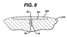
- a cross-sectional view illustrating the device 10 engaged in bone 210 while maintaining the matrix 220 on bone surface 201 is seen in FIG. 8 .
- FIG. 12 illustrates a matrix 220 mounted to bone surface 201 of bone 210 having multiple fixation devices of the present invention installed to secure the matrix 220 .
- the number, anatomical location and orientation of fixation devices 10 necessary to provide sufficiently effective fixation will vary with the size and type of implant or matrix, the type of tissue, the age of the patient, the size of the patient's defect, the size of the fixation devices, the material of construction of the fixation devices, the load on the tissue at the repair site, etc.
- the size of the fixation devices of the present invention will vary in accordance with a number of variables including the specific design of the device, the materials of construction, the specific application for the devices, the type of surgical procedure, etc.
- the size of the matrices fixated with these devices will similarly vary.
- the Figures which are part of this specification are merely schematic and illustrative of the device and method of the present invention; the actual dimensions of the devices and matrices may vary in practice.
- a punch tool 400 was used to create the two requisite bore holes in the subchondral bone to receive one graft fixation device of the present invention. Only one polydioxanone device (4 mm tip-to-tip distance) was used to attach each matrix. To create the bore holes, the punch tool was centered in the defect, oriented in the sagittal plane, and hit or “tapped” with a slap hammer repeatedly until it penetrated several millimeters into the subchondral bone. Next, a 7 mm diameter circular collagen matrix, saturated with saline, was placed in the defect and then blotted dry to remove excess saline.
- the device and inserter tool were centered above the matrix and oriented in the sagittal plane.
- the surgeon then located the previously created bore holes by slowly advancing the distal tips of the inserter through the matrix.
- a hammer was used to fully advance the inserter tool (and implantation members 20 of the fixation device 10 ) through the matrix and into the subchondral bone.
- the inserter tool had a depth stop to prevent the implantation members 20 from being inserted too deeply, thereby assuring the proper placement of the implantation members through the matrix.
- FIG. 9 Another embodiment of the fixation device of the present invention having multiple retention members is seen in FIG. 9 .
- the device 300 is seen to have a pair of implantation members 310 .
- the implantation members 310 are substantially cylindrical members having longitudinal axis 311 , distal ends 314 and proximal ends 312 .
- Each implantation member 310 is seen to have a longitudinal passage 320 .
- the members 310 are seen to have a distal frustoconical end 330 , outer surface 350 , and ridges 355 extending outward from surface 350 .
- the members 310 are seen to be connected by a pair of retention members 340 , having first and second ends 342 and 344 respectively.
- FIGS. 13-17 Yet another embodiment of a fixation device of the present invention is illustrated in FIGS. 13-17 .
- the graft fixation device 500 is seen to have implantation members 520 .
- the implantation members 520 are seen to be elongated members, preferably having a substantially cylindrical shape.
- the members 520 may have other geometric shapes including conical, pyramidal, polygonal, cubic, spherical, etc.
- the implantation members 520 are seen to have distal ends 522 and proximal ends 524 .
- Each implantation member 520 is seen to have an outer surface 528 and a longitudinal axis 529 .
- Each member 520 is also seen to have longitudinal passage 535 extending therethrough.
- the implantation members 520 are also seen to have optional frustoconical ends 530 , and proximal end face surfaces 532 . Although it is preferred that endface surfaces 532 be flat, endface surfaces 532 may also be angled, concave, convex, etc.
- Each endface surface 532 is seen to have central circular opening 536 in communication with passage 535 .
- central opening 536 will have a circular cross-section, but it may have other geometric cross-sections as well including elliptical, polygonal, square, rectangular, combinations thereof and the like.
- Members 520 are also seen to have distal end face surfaces 537 having circular openings 538 in communication with passages 535 .
- endface surfaces 537 have a sharp edge configuration, but may also have various widths with a rounded or flat configuration.
- the annular end face surface 537 is of de minimis thickness around opening 538 , however this thickness would typically increase in the absence of a frustoconical end.
- the end surface 537 could have various widths as previously mentioned.
- Also seen to extend out from the surface 528 of member 520 are a series of optional projections 540 having tissue engagement edges 544 .
- the surface 528 of the member 520 will be smooth, however, it will be appreciated that surface 528 could be rough, or could have a variety of conventional projections such as cones, hemispheres, rods, hooks, etc., and the like and equivalents thereof.
- the device 500 is seen to have graft retention member 550 connecting the implantation members 520 .
- Retention member 550 is seen to be a band-like member preferably having an oval cross-section.
- the retention member 550 is seen to have first end 552 , second end 554 and central section 555 .
- First end 552 is seen to extend up from proximal endface surface 532 of the first member 520 while end 554 is seen to extend up from the proximal endface surface 532 of the other member 520 .
- a section 557 of end 552 is seen to extend out from section 539 of surface 528 , while section 558 of second end 554 is also seen to extend out from a section 539 of surface 528 .
- the ends 554 and 552 of retention member 550 may if desired extend from or be mounted to any section of outer surface 528 .
- the connecting member 550 is seen to be preferably bent or shaped into three segments including top segment 555 and leg segments 556 .
- the top segment 555 is seen to an arc shaped member, and the leg segments 56 are seen to be preferably perpendicular to surfaces 532 .
- connecting member 550 may have other geometric configurations including semicircular, arced, curved, triangular, polygonal, V-shaped, and the like and combinations thereof.
- connecting member 550 may be permanently affixed to the implantation members 520 , or may be removably attached thereto in a variety of conventional manners, for example, a ball and socket joint, a plug joint, etc.
- Member 550 may be rigid or flexible. Member 550 will have a sufficient surface area to effectively retain a tissue-engineered matrix in place on a bone or other body surface.
- connecting member 550 will have an oval cross-section, but may have other geometric cross-sections as well including circular, elliptical, polygonal, square, rectangular, combinations thereof and the like. Member 550 may be rigid or flexible, and may have a single filamentary structure or have multiple interconnected filaments or members.
- FIGS. 35 and 36 An embodiment of graft fixation device 500 having lateral wing members 580 is seen in FIGS. 35 and 36 .
- the device 500 is seen to have wing members 580 extending laterally from the central section 555 of the connecting member (or graft retention member) 550 .
- the wing members 580 are preferably elongated members having a distal end 584 and a proximal end 582 . Extending from the distal end 584 is a rounded nose section 590 . If desired nose section 590 may have other geometric configurations including conical, pyramidal, and the like, etc.
- the wing members 580 are seen to have outer surface 586 . As seen in FIG.
- the wing members 580 are seen to have a circular cross-section, tapering from a maximum dimension at proximal end 582 . There is seen to be a transition section 592 between the proximal end 582 and the top 555 of retention member 550 . If desired, the diameter may be constant along the length of the wing member 580 .
- the wing members 580 may have other cross-sectional configurations as well including oval, square, rectangular, triangular, polygonal, curved, combinations thereof and the like. The length of the wing members 580 is sufficient to provide effective retention of an implant graft. If desired, although not preferred, the wing members 580 may short or of medium length, rather than elongated.
- the width or diameter of the wing members will vary to provide sufficiently effective graft retention.
- a single wing member 580 may be used, or a plurality of wing members 580 may be used with device 500 .
- the retention devices 500 having wing members 580 are illustrated implanted in bone and securing a graft matrix implant in FIG. 36 .
- the method of implanting a device having wing members 580 is substantially similar, and having the same steps, to implanting a device 500 without wing members 580 as described and illustrated previously herein. As seen in FIG. 36 , at least a portion of surface 586 engages the top of the matrix 220 on bone 210 .
- the insertion device 600 is seen to be a substantially cylindrical member having proximal end 610 and distal end 620 .
- Proximal end 610 is seen to have a flat end surface 612 .
- Frustoconical end section 630 is seen to extend distally from distal end 620 , although device 600 may have other configurations as well.
- distal end 620 can have any tapered or curved configuration, but it is preferred that it have a frustoconical end section extending therefrom.
- the frustoconical end section 630 is seen to have outer surface 632 and distal tip 640 .
- the member 600 is also seen to have exterior surface 650 . Extending through member 600 is the longitudinal passage 660 having first circular opening 665 in communication therewith, and second circular opening 667 in tip 640 in communication therewith.
- the insertion members 600 are used in combination with the fixation members of the present invention to engage the fixation member in bone simultaneously with tapping the bore holes into bone, thereby eliminating the need for a separate step to form the bore holes prior to inserting the fixation member.
- a fixation member 500 is mounted to prongs 700 extending from the distal end 415 of the shaft 405 of instrument 400 .
- Each prong 700 is seen to have first cylindrical section 710 extending from the distal end 415 of the shaft 405 .
- Each cylindrical section 710 is seen to have proximal end 711 and distal end 712 , and receiving grooves 715 .
- Extending from the distal end 712 of each first section 710 is the central pin section 720 .
- Central pin section 720 is seen to have proximal end 722 and distal end 724 .
- Extending distally from distal end 724 of central pin section 720 is the distal pin member 730 .
- Distal pin member 730 is seen to have proximal end 732 and distal pointed end 734 .
- the insertion member 600 may be molded into or affixed to the distal end of an implantation member 520 , thereby forming a unitary structure as seen in FIG. 31 and FIG. 32 .
- the insertion member 600 may be mounted to the distal end of an implantation member 520 in a conventional manner by gluing, cementing, mechanical fastening, friction fit and the like and equivalents thereof.
- FIGS. 33 and 34 The combination of a unitary implantation device 500 having wing members 580 as previously described and an insertion member 600 is illustrated in FIGS. 33 and 34 .
- This combination with wing members 580 securing a matrix 220 to bone 210 is seen in FIG. 34 .
- the insertion members 600 may be separate from the insertion device 500 having wing members 580 .
- the method of inserting this combination having wing members 580 is substantially identical to that described and illustrated herein.
- fixation member 500 of the present invention are used to affix a matrix to bone in the following manner.
- the implantation members 520 of a fixation device 500 are placed upon prongs 700 of an instrument 400 such that the leg members 556 are at least partially engaged in grooves 715 in first section 710 (see FIG. 21 ), and, intermediate sections 720 of pin members 700 are engaged in passages 535 of implantation members 520 , while pin members 730 extend out from the distal ends of the implantation members 520 .
- insertion members 600 are placed over the pin members 730 , such that the pin members 730 are engaged in passages 660 , and such that the pointed piercing ends 734 extend beyond the distal ends 640 of the insertion member 660 .
- the tool 400 and the assembly consisting of fixation device 500 and insertion member 600 is placed over a tissue matrix 220 placed upon a bone 210 .
- the piercing points are then pressed through matrix 220 to contact the surface 211 of bone 210 .
- a slap-hammer section of instrument 400 is engaged to drive the piercing points 734 , insertion members 600 and implantation members 520 into the bone 210 as bore holes 200 are formed in the bone.
- the instrument 400 is then withdrawn proximately, thereby removing the intermediate sections 720 of prongs 700 from the implantation members 520 and the pin members 730 from the insertion members 600 , leaving the insertion members 600 and the implantation members 520 securely in the bone (as seen in FIG. 20 ).
- fixation devices of the present invention It is particularly preferred to use conventional remote visualization surgical procedures when inserting the fixation devices of the present invention. For example, inserting a scope through a trocar cannula into the joint or body cavity, while insufflating the joint or body cavity.
- the insertion members 600 will typically be made from a strong, hard, bioabsorbable material such that they can be driven into bone without fracturing or breaking.
- Examples of the types of materials which can be used to make the insertion member 600 include polylactic acid, polyglycolic acid, tricalcium phosphate, calcium phosphate, tetracalcium phosphate and hydroxyapatite, and any copolymers, mixtures or blends thereof.
- the insertion member 600 assists in forming the bore holes 200 while protecting the implantation members 520 .
- FIGS. 22-23 illustrate a disposable distal end assembly 800 for an instrument 400 of the present invention.
- the distal end 415 of the shaft 405 of instrument 400 have screw threads 418 , although other conventional detachable mounts may be used, for example a bayonet-type mount, locking levers and tabs, male and female mating sections, etc.
- the assembly 800 consists of housing 810 having proximal end 811 and distal end 817 . Housing 810 is seen to have hollow cavity 815 therein. Cavity 815 is seen to be in communication with proximal end opening 812 and distal end openings 820 . Member 810 is seen to have outer surface 822 .
- Outer surface 822 is preferably knurled to facilitate the grasping and turning of the housing 810 .
- Housing 810 is further seen to have distal end surface 825 .
- the outer surface 822 is seen to have a tapered section 823 that tapers toward end face 825 .
- Contained within cavity 815 , on inner surface 818 are the screw threads 819 .
- Assembly 800 is also seen to have driving pin members 830 .
- Each driving pin member 830 is seen to have proximal disk member 832 mounted to proximal end 831 , shaft section 834 and distal pointed end 838 .
- Surrounding each opening 820 on the interior of the member 810 are the annular recesses 840 .
- the assembly 800 is mounted to the distal end 415 of the instrument 400 in the following manner.
- the pins 830 are inserted into cavity 815 and through openings 820 such that the shafts 834 and distal piercing points 838 extend through end face 825 , and the disk members 832 are contained within the annular recesses 840 .
- the housing 810 is mounted upon the threads of distal end 415 such that threads 418 engage mating threads 819 , and screwed further such that the proximal end surfaces 833 of the disk members 832 are in contact with the distal end face 416 of distal end 415 .
- the assembly 800 is removed and discarded.
- a new sterile assembly 800 is utilized with a cleaned and sterilized instrument 400 for each new procedure.
- a disposable end assembly 900 for mounting to an insertion instrument 250 is illustrated.
- the insertion member 250 is seen to have distal end 264 , having endface 265 and screw threads 266 .
- the assembly 900 is seen to have housing 950 .
- Housing 950 has proximal end 952 and distal end 956 and exterior surface 954 . Extending from distal end 956 is the plate member 960 .
- Plate member 960 is seen to have distal surface 962 .
- the exterior surface 954 is seen to have optional knurling and distal tapered section 957 tapering into plate member 960 .
- Housing 950 is seen to have internal cavity 955 .
- Housing 950 is also seen to have proximal opening 951 in communication with cavity 955 and distal openings 970 also in communication therewith. Housing 950 is seen to have internal screw threads 959 extending from internal surface 958 . Also contained within the interior of housing 950 in the distal end 956 is the recessed groove 980 . Assembly 900 is mounted to the distal end 264 of instrument 250 in the following manner. Pins 910 are inserted through cavity 950 and openings 970 such that proximal members 922 are engaged in groove 980 . Sections 920 and 930 of pins 910 extend through openings 970 . Sections 920 are seen to have grooves 925 .
- the housing 950 is screwed on to distal end 264 such that the threads 266 engage the mating internal threads 959 of housing 950 .
- the housing is tightened until the distal end surface 265 of the distal end 264 engages the top surfaces 923 of members 922 .
- the assembly 900 is removed from instrument 250 and discarded.
- a new sterile assembly 900 is utilized with a cleaned and sterilized instrument 250 for each new procedure.
- FIGS. 37-41 Another alternate embodiment of the graft fixation members of the present invention is illustrated in FIGS. 37-41 .
- An embodiment of a graft fixation device 1000 having optional lateral wing members 1080 is seen. Referring to FIGS. 37 and 38 , the device 1000 is seen to have wing members 1080 extending laterally from the central section 1055 of the connecting member (or graft retention member) 1050 .
- Retention member 1050 is seen to be a band-like member preferably having an oval cross-section (See FIGS. 40 and 41 ).
- the retention member 1050 is seen to have first end section 1052 , second end section 1054 and central section 1055 .
- First end 1052 is seen to extend up from proximal endface surface 1112 of the first member 1100 while end 1054 is seen to extend up from the proximal endface surface 1112 of the other member 1100 .
- a section 1057 of end 1052 is seen to extend out from a section of outer surface 1114
- a section 1058 of second end 1054 is also seen to extend out from a section of outer surface 1114 .
- the ends 1054 and 1052 of retention member 1050 may if desired extend from or be mounted to any section of outer surface 1114 , or extend solely from proximal end surfaces 1112 .
- the connecting or retention member 1050 is seen to be preferably bent or shaped into three segments including top segment or central section 1055 and leg segments or end sections 1056 .
- connecting member 1050 may have other geometric configurations including semicircular, arced, curved, triangular, polygonal, V-shaped, and the like and combinations thereof.
- the ends 1052 and 1054 of connecting member 1050 may be permanently affixed to the implantation members 1110 , or may be removably attached thereto in a variety of conventional manners, for example, a ball and socket joint, a plug joint, etc.
- Member 1050 may be rigid or flexible. Member 1050 will have a sufficient surface area to effectively retain a tissue-engineered matrix in place on a bone or other body surface.
- connecting member 1050 will have an oval cross-section, but may have other geometric cross-sections as well including circular, elliptical, polygonal, square, rectangular, combinations thereof and the like.
- Member 1050 may be rigid or flexible, segmented, or may have a single filamentary structure or have multiple interconnected filaments or members.
- the optional and preferred wing members 1080 are preferably elongated members having a distal end 1084 and a proximal end 1082 Extending from the distal end 1084 is a rounded nose section 1090 .
- nose section 1090 may have other geometric configurations including conical, pyramidal, and the like, etc.
- the wing members 1080 are seen to have outer surface 1086 .
- the wing members 1080 preferably have an elliptical or circular cross-section, tapering from a maximum dimension at proximal end 1082 .
- the diameter may be constant along the length of the wing member 1080 .
- the wing members 1080 may have other cross-sectional configurations as well including oval, square, rectangular, triangular, polygonal, curved, combinations thereof and the like.
- the length of the wing members 1080 is sufficient to provide effective retention of an implant graft and maintain contact of the implant against a bone, for example, a bone surface.
- the wing members 1080 may be of short or medium length, rather than elongated.
- the width or diameter of the wing members will vary to provide sufficiently effective graft or matrix retention and contact of the graft or matrix with the bone.
- it is preferred to have two opposed wing members 1080 extending laterally from the retention member 1050 a single wing member 1080 may be used, or a plurality of wing members 1080 may be used with device 1000 .
- the members 1100 are seen to have a top section and a bottom section.
- the top section consists of implantation member 1110 and a lower section consists of penetrating insertion member 1150 .
- the upper implantation member 1110 is seen to be a substantially cylindrical member having a proximal end 1120 and a distal end 1130 . Preferably the distal end has a frustoconical configuration.
- Extending through implantation member section 1110 is the passage 1140 .
- Passage 1140 is seen to be an elongated passage.
- An opening 1141 in proximal endface 1112 of implantation member 1110 is seen to be in communication with the passage 1140 .
- Distal opening 1145 is also seen to communicate with passage 1140 .
- the implantation member section 1110 is seen to have outer side surface 1114 . Extending radially outward from outer surface 1114 is at least one engagement member 1117 having edge 1118 forming a ridge.
- the penetrating insertion member sections 1150 are seen to have proximal ends 1160 and distal ends 1170 .
- the distal end 1170 preferably has a distal penetrating tip 1175 .
- Tip 1175 may be blunt or sharp.
- Each penetrating insertion section 1150 is seen to be a substantially conically shaped member having proximal end face 1165 having opening 1191 therein.
- the insertion member sections 1150 are further seen to have longitudinal passages 1190 having blind end walls 1195 . Passage 1190 is seen to be in communication with opening 1191 which in turn is in communication with opening 1145 , and accordingly passages 1140 and 1190 are in communication with each other.
- passage 1190 can continue through the length of insertion member 1150 , with a constant or smaller or tapering diameter, and blind end wall 1195 could be replaced with a flange having an opening or a member protruding radially inward into passage 1190 to engage the distal end of a mounting pin of an insertion instrument.
- the graft fixation devices 1000 are made in a conventional manner preferably from bioabsorbable materials as previously mentioned for other embodiments of the fasteners disclosed herein. It is particularly preferred to co-mold the implantation member section and the insertion member section, although other conventional means of affixing the implantation member and the insertion may be used including mechanical fastening, welding, adhesives, glues, and the like and combinations thereof.
- the penetrating insertion member sections 1150 will typically be made from a strong, hard, bioabsorbable material such that they can be driven into bone without fracturing or breaking.
- Examples of the types of materials which can be used to make the penetrating insertion members 1150 include polylactic acid, polyglycolic acid, tricalcium phosphate, calcium phosphate, tetracalcium phosphate and hydroxyapatite, and any copolymers, mixtures or blends thereof and equivalents thereof.
- a conventional biocompatible material which is not bioabsorbable or biodegradable, such as titanium, stainless steel, ceramics, Nitinol nickel-titanium alloy, polysulfone, acetal and the like and equivalents and combinations thereof.
- the penetrating insertion members 1150 can be made from conventional processes, including machining, molding, combinations and equivalents thereof and the like.
- the penetrating insertion members 1150 assist in forming the implantation or bore holes 200 while protecting the implantation member sections 1110 .
- the implantation member sections 1110 can be made from conventional bio-compatible materials, including absorbable and non-absorbable materials, as well as biodegradable materials.
- the non-absorbable materials which can be utilized include conventional biocompatible materials such as stainless steel, polyethylene, Teflon, Nitinol, non-absorbable polymers, other bio-compatible metals, ceramics, combinations thereof and the like.
- the absorbable materials which can be used to manufacture the implantation members 1110 will typically include those conventional bioabsorbable or bioresorbable materials known in this art which can be effectively molded or machined.
- the bio-absorbable and bio-resorbable materials include polylactic acid, polydioxanone, polycaprolactone, polyglycolic acid, polygalactic acid, other known biocompatible bioabsorbable and bioresorbable polymers, ceramics, composites, combinations thereof and the like and equivalents thereof. If desired the implantation members 1110 and the insertion members 1150 can be made from the same material.
- the graft fixation devices 1000 having wing members 1080 are illustrated implanted in bone 205 and securing a graft matrix implant 220 to the surface 210 of the bone 205 in FIG. 39 .
- FIGS. 42-45 An instrument 1400 and an instrument assembly 1600 useful for implanting graft fixation devices 1000 is illustrated in FIGS. 42-45 .
- the instrument 1400 is seen to have shaft 1410 having proximal end 1415 and distal end 1418 . Extending proximally from proximal end surface 1416 of proximal end 1415 is threaded rod connector 1417 .
- the shaft 1410 is seen to have a tapered end section 1430 extending from distal end 1418 . Extending laterally (radially) out from shaft 1410 toward proximal end 1415 are the guide pins 1420 .
- the sleeve member 1470 is seen to be a tubular member having distal end 1477 and proximal end 1472 .
- the member 1470 has inner or longitudinal passage 1480 in communication with distal opening 1485 and proximal opening 1482 .
- the member 1470 has outer surface outer surface 1475 , and a proximal handle section surface 1476 extending therefrom.
- the sleeve member 1470 is seen to have a plurality of openings 1490 extending therethrough in the distal end 1477 in communication with inner passage 1480 .
- the openings 1490 act as windows so that the interior of sleeve member 1470 may be viewed adjacent thereto.
- the sleeve member 1470 is seen to have opposed longitudinal slots 1492 extending therethrough in the proximal end 1472 .
- the sleeve member 1470 is concentrically and slidably mounted over shaft 1410 such that the pins 1420 are contained within slots 1492 , and mounting pins 1450 are contained within passage 1480 adjacent to distal end 1477 of sleeve member 1470 , or extending out from distal end 1477 of sleeve member 1470 .
- FIG. 43 An assembled insertion instrument assembly 1600 is seen in FIG. 43 , having the sleeve member 1470 in the maximum proximal position to expose the mounting members 1450 .
- the insertion instrument assembly 1600 is seen to have insertion instrument 1400 with an optional conventional slap hammer assembly 1530 mounted to the proximal end 1415 of shaft 1410 .
- the slap hammer assembly 1530 is seen to have a tapered connecting section 1540 having distal end 1541 and proximal end 1546 .
- Distal end 1541 is seen to have threaded cavity 1542 extending therein
- proximal end 1546 is seen to have threaded cavity 1547 extending therein.
- the slap hammer assembly 1530 is seen to have support rod 1550 having proximal end flange 1555 and distal threaded end 1558 .
- the assembly has handle member 1560 slidably mounted on rod 1550 .
- Handle member 1560 is seen to have longitudinal passage 1568 , proximal flange member 1562 and distal flange member 1564 .
- the threaded end 1558 of support rod 1550 is engaged in threaded cavity 1547 of tapered connecting section 1540 .
- the threaded rod connector 1417 of shaft 1410 is similarly engaged in threaded cavity 1542 of connecting section 1540 .
- the insertion instrument 1400 may be used without slap hammer assembly to insert graft fixation devices of the present invention.
- the proximal end 1415 of shaft 1410 may be connected to other conventional force transmitting devices, or the proximal end 1415 may be hammered directly by the surgeon using a conventional orthopedic hammer.
- a method of implanting a graft fixation device 1000 , having optional wing members 1080 , using an insertion instrument assembly 1600 is described as follows. It should be noted that although it is preferred to insert the graft fixation devices 1000 directly into bone using the insertion instrument assembly 1600 without pre-drilling or otherwise pre-creating bore holes in bone, the device 1000 can also be utilized to affix a matrix to bone where the bore holes are pre-drilled or otherwise pre-created.
- a device 1000 is mounted to the mounting pins 1450 of insertion instrument 1400 of insertion assembly 1600 .
- the sleeve member 1470 is moved distally to cover the insertion device 1000 , thereby protecting the device 1000 , and the surgeon locates the device at the surgical site using insertion instrument assembly 1600 .
- the surgeon slides the sleeve 1470 proximally to uncover the insertion device 1000 .
- the distal end of penetrating insertion member 1150 is contacted with the top 221 of the matrix 220 .
- the optional slap hammer assembly 1530 is manipulated to drive the penetrating insertion member 1150 and the implantation member 1100 into the bone 205 .
- This causes the central section 1055 of retention member 1050 and the lateral wing member 1080 to engage the matrix 220 and substantially cause the bottom surface 222 of the matrix 220 to engage the surface 210 of the bone 205 .
- Multiple fixation devices 1000 are inserted in the same manner into the matrix 220 in a spatial configuration sufficient to effectively affix or mount the matrix 220 to the bone 205 .
- the distal flat end faces 1458 of pins 1450 contact end walls 1195 of passage 1190 causing a transfer of force from the mounting pins 1450 to penetrating insertion members 1150 thereby driving the device the penetrating insertion members 1150 and the implantation members 1110 into the bone 205 .
- fixation devices of the present invention and the combination of the fixation devices with insertion members, and methods of using such devices and combinations, of the present invention have many advantages.
- the advantages include providing a fast and routine way to fixate a matrix of tissue engineered tissue or other tissue.
- the fixation devices and combination because they eliminate the need for suture knot tying, can be utilized in arthroscopic surgical procedures that require a minimum of surgical incisions and thus greatly reduce patient morbidity.
- the fixation devices and combination have been demonstrated to provide excellent matrix fixation without damaging the surrounding normal cartilaginous tissue, unlike the conventional fixation of chondral defect matrices with traditional suture that must be passed through (and thus damage) the surrounding tissue.
Abstract
Description
-
- Group 1: defect filled with a collagen matrix, fixed with the graft fixation device of the present invention.
- Group 2: defect filled with a collagen matrix, fixed with 9-0 absorbable Vicryl™ suture (interrupted stitch technique, approximately 12 strands per matrix).
- Group 3: unfilled defect (control group).
Claims (13)
Priority Applications (7)
| Application Number | Priority Date | Filing Date | Title |
|---|---|---|---|
| US10/142,399 US7214232B2 (en) | 1999-07-23 | 2002-05-09 | Graft fixation device |
| EP03252877A EP1360936B1 (en) | 2002-05-09 | 2003-05-08 | Graft fixation device |
| DE60316862T DE60316862T2 (en) | 2002-05-09 | 2003-05-08 | Fastening device for an implant |
| AU2003204120A AU2003204120B2 (en) | 2002-05-09 | 2003-05-09 | Graft fixation device |
| CA2428348A CA2428348C (en) | 2002-05-09 | 2003-05-09 | Graft fixation device |
| JP2003131884A JP4397622B2 (en) | 2002-05-09 | 2003-05-09 | Graft fixation device |
| JP2009137882A JP5323588B2 (en) | 2002-05-09 | 2009-06-09 | Device for inserting a graft fixation member |
Applications Claiming Priority (4)
| Application Number | Priority Date | Filing Date | Title |
|---|---|---|---|
| US09/360,367 US6179840B1 (en) | 1999-07-23 | 1999-07-23 | Graft fixation device and method |
| US09/535,183 US6497707B1 (en) | 1999-07-23 | 2000-03-27 | Graft fixation device combination |
| US09/793,036 US6402766B2 (en) | 1999-07-23 | 2001-02-26 | Graft fixation device combination |
| US10/142,399 US7214232B2 (en) | 1999-07-23 | 2002-05-09 | Graft fixation device |
Related Parent Applications (1)
| Application Number | Title | Priority Date | Filing Date |
|---|---|---|---|
| US09/793,036 Continuation-In-Part US6402766B2 (en) | 1999-07-23 | 2001-02-26 | Graft fixation device combination |
Publications (2)
| Publication Number | Publication Date |
|---|---|
| US20020169465A1 US20020169465A1 (en) | 2002-11-14 |
| US7214232B2 true US7214232B2 (en) | 2007-05-08 |
Family
ID=29249836
Family Applications (1)
| Application Number | Title | Priority Date | Filing Date |
|---|---|---|---|
| US10/142,399 Expired - Lifetime US7214232B2 (en) | 1999-07-23 | 2002-05-09 | Graft fixation device |
Country Status (6)
| Country | Link |
|---|---|
| US (1) | US7214232B2 (en) |
| EP (1) | EP1360936B1 (en) |
| JP (2) | JP4397622B2 (en) |
| AU (1) | AU2003204120B2 (en) |
| CA (1) | CA2428348C (en) |
| DE (1) | DE60316862T2 (en) |
Cited By (161)
| Publication number | Priority date | Publication date | Assignee | Title |
|---|---|---|---|---|
| WO2003007805A2 (en) | 2001-07-16 | 2003-01-30 | Depuy Products, Inc. | Cartilage repair apparatus and method |
| US20060058802A1 (en) * | 2004-09-06 | 2006-03-16 | Hakon Kofoed | Fixation implant for a bone graft within a joint for the purpose of ensuring arthrodesis of the joint |
| US20100125301A1 (en) * | 2008-11-20 | 2010-05-20 | Kyle Kinmon | Surgical device, system and method of use thereof |
| US20100125275A1 (en) * | 2008-11-20 | 2010-05-20 | Kyle Kinmon | Surgical device, system and method of use thereof |
| US7780701B1 (en) | 2003-08-13 | 2010-08-24 | Biomet Sports Medicine, Llc | Suture anchor |
| US7819886B2 (en) | 2004-10-08 | 2010-10-26 | Tyco Healthcare Group Lp | Endoscopic surgical clip applier |
| US7905890B2 (en) | 2004-10-08 | 2011-03-15 | Tyco Healthcare Group Lp | Endoscopic surgical clip applier |
| US8016867B2 (en) | 1999-07-23 | 2011-09-13 | Depuy Mitek, Inc. | Graft fixation device and method |
| US8056565B2 (en) | 2008-08-25 | 2011-11-15 | Tyco Healthcare Group Lp | Surgical clip applier and method of assembly |
| US8128643B2 (en) | 2006-10-17 | 2012-03-06 | Tyco Healthcare Group Lp | Apparatus for applying surgical clips |
| US8267944B2 (en) | 2008-08-29 | 2012-09-18 | Tyco Healthcare Group Lp | Endoscopic surgical clip applier with lock out |
| US8382773B2 (en) | 2007-03-26 | 2013-02-26 | Covidien Lp | Endoscopic surgical clip applier |
| US8403945B2 (en) | 2010-02-25 | 2013-03-26 | Covidien Lp | Articulating endoscopic surgical clip applier |
| US8403946B2 (en) | 2010-07-28 | 2013-03-26 | Covidien Lp | Articulating clip applier cartridge |
| US8409223B2 (en) | 2008-08-29 | 2013-04-02 | Covidien Lp | Endoscopic surgical clip applier with clip retention |
| US8409222B2 (en) | 2004-10-08 | 2013-04-02 | Covidien Lp | Endoscopic surgical clip applier |
| US8449561B2 (en) | 1999-07-23 | 2013-05-28 | Depuy Mitek, Llc | Graft fixation device combination |
| US8465502B2 (en) | 2008-08-25 | 2013-06-18 | Covidien Lp | Surgical clip applier and method of assembly |
| US8506580B2 (en) | 2007-04-11 | 2013-08-13 | Covidien Lp | Surgical clip applier |
| US8545486B2 (en) | 2009-12-15 | 2013-10-01 | Covidien Lp | Surgical clip applier |
| US8585717B2 (en) | 2008-08-29 | 2013-11-19 | Covidien Lp | Single stroke endoscopic surgical clip applier |
| US8668718B2 (en) | 2009-06-04 | 2014-03-11 | Rotation Medical, Inc. | Methods and apparatus for fixing sheet-like materials to a target tissue |
| US8734469B2 (en) | 2009-10-13 | 2014-05-27 | Covidien Lp | Suture clip applier |
| US8864780B2 (en) | 2011-02-15 | 2014-10-21 | Rotation Medical, Inc. | Methods and apparatus for delivering and positioning sheet-like materials |
| US8968337B2 (en) | 2010-07-28 | 2015-03-03 | Covidien Lp | Articulating clip applier |
| US9011464B2 (en) | 2010-11-02 | 2015-04-21 | Covidien Lp | Self-centering clip and jaw |
| US9033201B2 (en) | 2011-02-15 | 2015-05-19 | Rotation Medical, Inc. | Methods and apparatus for fixing sheet-like materials to a target tissue |
| US9101460B2 (en) | 2009-01-08 | 2015-08-11 | Rotation Medical, Inc. | Implantable tendon protection systems and related kits and methods |
| US9107661B2 (en) | 2011-12-19 | 2015-08-18 | Rotation Medical, Inc. | Fasteners and fastener delivery devices for affixing sheet-like materials to bone or tissue |
| US9113977B2 (en) | 2011-02-15 | 2015-08-25 | Rotation Medical, Inc. | Guidewire having a distal fixation member for delivering and positioning sheet-like materials in surgery |
| US9113892B2 (en) | 2013-01-08 | 2015-08-25 | Covidien Lp | Surgical clip applier |
| US9125650B2 (en) | 2011-12-19 | 2015-09-08 | Rotation Medical, Inc. | Apparatus and method for forming pilot holes in bone and delivering fasteners therein for retaining an implant |
| US9179961B2 (en) | 2009-06-04 | 2015-11-10 | Rotation Medical, Inc. | Methods and apparatus for deploying sheet-like materials |
| US9179910B2 (en) | 2009-03-20 | 2015-11-10 | Rotation Medical, Inc. | Medical device delivery system and method |
| US9186153B2 (en) | 2011-01-31 | 2015-11-17 | Covidien Lp | Locking cam driver and jaw assembly for clip applier |
| US9186136B2 (en) | 2009-12-09 | 2015-11-17 | Covidien Lp | Surgical clip applier |
| US9198751B2 (en) | 2011-02-15 | 2015-12-01 | Rotation Medical, Inc. | Methods and apparatus for delivering and positioning sheet-like materials in surgery |
| US9198750B2 (en) | 2010-03-11 | 2015-12-01 | Rotation Medical, Inc. | Tendon repair implant and method of arthroscopic implantation |
| US9204940B2 (en) | 2011-02-15 | 2015-12-08 | Rotation Medical, Inc. | Anatomical location markers and methods of use in positioning sheet-like materials during surgery |
| US9271726B2 (en) | 2011-12-19 | 2016-03-01 | Rotation Medical, Inc. | Fasteners and fastener delivery devices for affixing sheet-like materials to bone or tissue |
| US9358015B2 (en) | 2008-08-29 | 2016-06-07 | Covidien Lp | Endoscopic surgical clip applier with wedge plate |
| US9364216B2 (en) | 2011-12-29 | 2016-06-14 | Covidien Lp | Surgical clip applier with integrated clip counter |
| US9364239B2 (en) | 2011-12-19 | 2016-06-14 | Covidien Lp | Jaw closure mechanism for a surgical clip applier |
| US9370356B2 (en) | 2011-12-19 | 2016-06-21 | Rotation Medical, Inc. | Fasteners and fastener delivery devices for affixing sheet-like materials to bone or tissue |
| US9408610B2 (en) | 2012-05-04 | 2016-08-09 | Covidien Lp | Surgical clip applier with dissector |
| US9414844B2 (en) | 2008-08-25 | 2016-08-16 | Covidien Lp | Surgical clip appliers |
| US20160262901A1 (en) * | 2013-03-14 | 2016-09-15 | Microaire Surgical Instruments Llc | Balloon Implant Device |
| US9532787B2 (en) | 2012-05-31 | 2017-01-03 | Covidien Lp | Endoscopic clip applier |
| US9687247B2 (en) | 2004-10-08 | 2017-06-27 | Covidien Lp | Apparatus for applying surgical clips |
| US9750500B2 (en) | 2013-01-18 | 2017-09-05 | Covidien Lp | Surgical clip applier |
| US9763668B2 (en) | 2004-10-08 | 2017-09-19 | Covidien Lp | Endoscopic surgical clip applier |
| US9775623B2 (en) | 2011-04-29 | 2017-10-03 | Covidien Lp | Surgical clip applier including clip relief feature |
| US9775624B2 (en) | 2013-08-27 | 2017-10-03 | Covidien Lp | Surgical clip applier |
| US9931124B2 (en) | 2015-01-07 | 2018-04-03 | Covidien Lp | Reposable clip applier |
| US20180092759A1 (en) * | 2009-03-27 | 2018-04-05 | Depuy Mitek, Llc | Methods and Devices for Delivering and Affixing Tissue Scaffolds |
| US9968362B2 (en) | 2013-01-08 | 2018-05-15 | Covidien Lp | Surgical clip applier |
| US10123796B2 (en) | 2014-11-04 | 2018-11-13 | Rotation Medical, Inc. | Medical implant delivery system and related methods |
| US10159491B2 (en) | 2015-03-10 | 2018-12-25 | Covidien Lp | Endoscopic reposable surgical clip applier |
| US10166026B2 (en) | 2015-08-26 | 2019-01-01 | Ethicon Llc | Staple cartridge assembly including features for controlling the rotation of staples when being ejected therefrom |
| US10172619B2 (en) | 2015-09-02 | 2019-01-08 | Ethicon Llc | Surgical staple driver arrays |
| US10258459B2 (en) | 2014-05-09 | 2019-04-16 | Rotation Medical, Inc. | Medical implant delivery system and related methods |
| US10265065B2 (en) | 2013-12-23 | 2019-04-23 | Ethicon Llc | Surgical staples and staple cartridges |
| US10265156B2 (en) | 2015-06-15 | 2019-04-23 | Rotation Medical, Inc | Tendon repair implant and method of implantation |
| USD847989S1 (en) | 2016-06-24 | 2019-05-07 | Ethicon Llc | Surgical fastener cartridge |
| US10292712B2 (en) | 2015-01-28 | 2019-05-21 | Covidien Lp | Surgical clip applier with integrated cutter |
| US10299842B2 (en) | 2013-12-20 | 2019-05-28 | Crossroads Extremity Systems, Llc | Bone plates with dynamic elements |
| USD850617S1 (en) | 2016-06-24 | 2019-06-04 | Ethicon Llc | Surgical fastener cartridge |
| US10314689B2 (en) | 2015-12-31 | 2019-06-11 | Rotation Medical, Inc. | Medical implant delivery system and related methods |
| US10357260B2 (en) | 2015-11-02 | 2019-07-23 | First Ray, LLC | Orthopedic fastener, retainer, and guide methods |
| US10376367B2 (en) | 2015-07-02 | 2019-08-13 | First Ray, LLC | Orthopedic fasteners, instruments and methods |
| US10390831B2 (en) | 2015-11-10 | 2019-08-27 | Covidien Lp | Endoscopic reposable surgical clip applier |
| US10426489B2 (en) | 2016-11-01 | 2019-10-01 | Covidien Lp | Endoscopic reposable surgical clip applier |
| US10492841B2 (en) | 2014-07-10 | 2019-12-03 | Crossroads Extremity Systems, Llc | Bone implant and means of insertion |
| US10492795B2 (en) | 2016-11-01 | 2019-12-03 | Covidien Lp | Endoscopic surgical clip applier |
| US10537324B2 (en) | 2016-12-21 | 2020-01-21 | Ethicon Llc | Stepped staple cartridge with asymmetrical staples |
| US10542979B2 (en) | 2016-06-24 | 2020-01-28 | Ethicon Llc | Stamped staples and staple cartridges using the same |
| US10548602B2 (en) | 2017-02-23 | 2020-02-04 | Covidien Lp | Endoscopic surgical clip applier |
| US10568616B2 (en) | 2014-12-17 | 2020-02-25 | Howmedica Osteonics Corp. | Instruments and methods of soft tissue fixation |
| US10582931B2 (en) | 2016-02-24 | 2020-03-10 | Covidien Lp | Endoscopic reposable surgical clip applier |
| US10603038B2 (en) | 2017-02-22 | 2020-03-31 | Covidien Lp | Surgical clip applier including inserts for jaw assembly |
| US10610236B2 (en) | 2016-11-01 | 2020-04-07 | Covidien Lp | Endoscopic reposable surgical clip applier |
| US10639032B2 (en) | 2017-06-30 | 2020-05-05 | Covidien Lp | Endoscopic surgical clip applier including counter assembly |
| US10639044B2 (en) | 2016-10-31 | 2020-05-05 | Covidien Lp | Ligation clip module and clip applier |
| US10653429B2 (en) | 2017-09-13 | 2020-05-19 | Covidien Lp | Endoscopic surgical clip applier |
| US10660651B2 (en) | 2016-10-31 | 2020-05-26 | Covidien Lp | Endoscopic reposable surgical clip applier |
| US10660723B2 (en) | 2017-06-30 | 2020-05-26 | Covidien Lp | Endoscopic reposable surgical clip applier |
| US10660725B2 (en) | 2017-02-14 | 2020-05-26 | Covidien Lp | Endoscopic surgical clip applier including counter assembly |
| US10675112B2 (en) | 2017-08-07 | 2020-06-09 | Covidien Lp | Endoscopic surgical clip applier including counter assembly |
| US10675043B2 (en) | 2017-05-04 | 2020-06-09 | Covidien Lp | Reposable multi-fire surgical clip applier |
| US10687810B2 (en) | 2016-12-21 | 2020-06-23 | Ethicon Llc | Stepped staple cartridge with tissue retention and gap setting features |
| US10702279B2 (en) | 2015-11-03 | 2020-07-07 | Covidien Lp | Endoscopic surgical clip applier |
| US10702278B2 (en) | 2014-12-02 | 2020-07-07 | Covidien Lp | Laparoscopic surgical ligation clip applier |
| US10702280B2 (en) | 2015-11-10 | 2020-07-07 | Covidien Lp | Endoscopic reposable surgical clip applier |
| US10709455B2 (en) | 2017-02-02 | 2020-07-14 | Covidien Lp | Endoscopic surgical clip applier |
| US10722236B2 (en) | 2017-12-12 | 2020-07-28 | Covidien Lp | Endoscopic reposable surgical clip applier |
| US10722235B2 (en) | 2017-05-11 | 2020-07-28 | Covidien Lp | Spring-release surgical clip |
| US10743887B2 (en) | 2017-12-13 | 2020-08-18 | Covidien Lp | Reposable multi-fire surgical clip applier |
| USD894389S1 (en) | 2016-06-24 | 2020-08-25 | Ethicon Llc | Surgical fastener |
| US10758245B2 (en) | 2017-09-13 | 2020-09-01 | Covidien Lp | Clip counting mechanism for surgical clip applier |
| US10758244B2 (en) | 2017-02-06 | 2020-09-01 | Covidien Lp | Endoscopic surgical clip applier |
| US10758228B2 (en) | 2015-11-03 | 2020-09-01 | Rotation Medical, Inc. | Fastener delivery system and related methods |
| US10765431B2 (en) | 2016-01-18 | 2020-09-08 | Covidien Lp | Endoscopic surgical clip applier |
| US10786273B2 (en) | 2018-07-13 | 2020-09-29 | Covidien Lp | Rotation knob assemblies for handle assemblies |
| US10786263B2 (en) | 2017-08-15 | 2020-09-29 | Covidien Lp | Endoscopic reposable surgical clip applier |
| US10786262B2 (en) | 2017-08-09 | 2020-09-29 | Covidien Lp | Endoscopic reposable surgical clip applier |
| US10806464B2 (en) | 2016-08-11 | 2020-10-20 | Covidien Lp | Endoscopic surgical clip applier and clip applying systems |
| US10806463B2 (en) | 2011-11-21 | 2020-10-20 | Covidien Lp | Surgical clip applier |
| US10828036B2 (en) | 2017-11-03 | 2020-11-10 | Covidien Lp | Endoscopic surgical clip applier and handle assemblies for use therewith |
| USD902405S1 (en) | 2018-02-22 | 2020-11-17 | Stryker Corporation | Self-punching bone anchor inserter |
| US10835368B2 (en) | 2017-12-07 | 2020-11-17 | Rotation Medical, Inc. | Medical implant delivery system and related methods |
| US10835260B2 (en) | 2017-09-13 | 2020-11-17 | Covidien Lp | Endoscopic surgical clip applier and handle assemblies for use therewith |
| US10835341B2 (en) | 2017-09-12 | 2020-11-17 | Covidien Lp | Endoscopic surgical clip applier and handle assemblies for use therewith |
| US10849630B2 (en) | 2017-12-13 | 2020-12-01 | Covidien Lp | Reposable multi-fire surgical clip applier |
| US10863992B2 (en) | 2017-08-08 | 2020-12-15 | Covidien Lp | Endoscopic surgical clip applier |
| US10898228B2 (en) | 2015-05-06 | 2021-01-26 | Rotation Medical, Inc. | Medical implant delivery system and related methods |
| US10905425B2 (en) | 2015-11-10 | 2021-02-02 | Covidien Lp | Endoscopic reposable surgical clip applier |
| US10925599B2 (en) | 2013-12-23 | 2021-02-23 | Ethicon Llc | Modular surgical instruments |
| US10932790B2 (en) | 2017-08-08 | 2021-03-02 | Covidien Lp | Geared actuation mechanism and surgical clip applier including the same |
| US10932791B2 (en) | 2017-11-03 | 2021-03-02 | Covidien Lp | Reposable multi-fire surgical clip applier |
| US10932793B2 (en) | 2016-01-11 | 2021-03-02 | Covidien Lp | Endoscopic reposable surgical clip applier |
| US10945734B2 (en) | 2017-11-03 | 2021-03-16 | Covidien Lp | Rotation knob assemblies and surgical instruments including the same |
| US10945725B2 (en) | 2017-02-06 | 2021-03-16 | Crossroads Extremity Systems, Llc | Implant inserter |
| US10945727B2 (en) | 2016-12-21 | 2021-03-16 | Ethicon Llc | Staple cartridge with deformable driver retention features |
| US10959737B2 (en) | 2017-12-13 | 2021-03-30 | Covidien Lp | Reposable multi-fire surgical clip applier |
| US10993715B2 (en) | 2016-12-21 | 2021-05-04 | Ethicon Llc | Staple cartridge comprising staples with different clamping breadths |
| US10993721B2 (en) | 2018-04-25 | 2021-05-04 | Covidien Lp | Surgical clip applier |
| US11000410B2 (en) | 2016-06-17 | 2021-05-11 | Gyroscope Therapeutics Limited | Guide apparatus for tangential entry into suprachoroidal space |
| US11020109B2 (en) | 2013-12-23 | 2021-06-01 | Ethicon Llc | Surgical stapling assembly for use with a powered surgical interface |
| US11033256B2 (en) | 2018-08-13 | 2021-06-15 | Covidien Lp | Linkage assembly for reusable surgical handle assemblies |
| US11051828B2 (en) | 2018-08-13 | 2021-07-06 | Covidien Lp | Rotation knob assemblies and surgical instruments including same |
| US11051827B2 (en) | 2018-01-16 | 2021-07-06 | Covidien Lp | Endoscopic surgical instrument and handle assemblies for use therewith |
| US11058432B2 (en) | 2015-01-15 | 2021-07-13 | Covidien Lp | Endoscopic reposable surgical clip applier |
| US11071553B2 (en) | 2016-08-25 | 2021-07-27 | Covidien Lp | Endoscopic surgical clip applier and clip applying systems |
| US11076851B2 (en) | 2014-11-04 | 2021-08-03 | Rotation Medical, Inc. | Medical implant delivery system and related methods |
| US11116514B2 (en) | 2017-02-06 | 2021-09-14 | Covidien Lp | Surgical clip applier with user feedback feature |
| US11116513B2 (en) | 2017-11-03 | 2021-09-14 | Covidien Lp | Modular surgical clip cartridge |
| US11123065B2 (en) | 2013-12-23 | 2021-09-21 | Cilag Gmbh International | Surgical cutting and stapling instruments with independent jaw control features |
| US11147566B2 (en) | 2018-10-01 | 2021-10-19 | Covidien Lp | Endoscopic surgical clip applier |
| US11179149B2 (en) | 2017-02-07 | 2021-11-23 | Crossroads Extremity Systems, Llc | Counter-torque implant |
| US20210386422A1 (en) * | 2020-06-16 | 2021-12-16 | Ortho Solutions Holdings Limited | Reinforced bridge superelastic bone compression staple and inserter system |
| US11202626B2 (en) | 2014-07-10 | 2021-12-21 | Crossroads Extremity Systems, Llc | Bone implant with means for multi directional force and means of insertion |
| US11213295B2 (en) | 2015-09-02 | 2022-01-04 | Cilag Gmbh International | Surgical staple configurations with camming surfaces located between portions supporting surgical staples |
| US11219456B2 (en) | 2015-08-26 | 2022-01-11 | Cilag Gmbh International | Surgical staple strips for permitting varying staple properties and enabling easy cartridge loading |
| US11219463B2 (en) | 2018-08-13 | 2022-01-11 | Covidien Lp | Bilateral spring for surgical instruments and surgical instruments including the same |
| US11246601B2 (en) | 2018-08-13 | 2022-02-15 | Covidien Lp | Elongated assemblies for surgical clip appliers and surgical clip appliers incorporating the same |
| US11253267B2 (en) | 2018-08-13 | 2022-02-22 | Covidien Lp | Friction reduction mechanisms for handle assemblies |
| US11259887B2 (en) | 2018-08-10 | 2022-03-01 | Covidien Lp | Feedback mechanisms for handle assemblies |
| US11278267B2 (en) | 2018-08-13 | 2022-03-22 | Covidien Lp | Latch assemblies and surgical instruments including the same |
| US11317951B2 (en) | 2013-12-20 | 2022-05-03 | Crossroads Extremity Systems, Llc | Bone plates with dynamic elements |
| US11344316B2 (en) | 2018-08-13 | 2022-05-31 | Covidien Lp | Elongated assemblies for surgical clip appliers and surgical clip appliers incorporating the same |
| US11376015B2 (en) | 2017-11-03 | 2022-07-05 | Covidien Lp | Endoscopic surgical clip applier and handle assemblies for use therewith |
| USD961081S1 (en) | 2020-11-18 | 2022-08-16 | Crossroads Extremity Systems, Llc | Orthopedic implant |
| US11457916B2 (en) | 2014-11-04 | 2022-10-04 | Rotation Medical, Inc. | Medical implant delivery system and related methods |
| US11517325B2 (en) | 2017-06-20 | 2022-12-06 | Cilag Gmbh International | Closed loop feedback control of motor velocity of a surgical stapling and cutting instrument based on measured displacement distance traveled over a specified time interval |
| US11524398B2 (en) | 2019-03-19 | 2022-12-13 | Covidien Lp | Gear drive mechanisms for surgical instruments |
| US11583291B2 (en) | 2017-02-23 | 2023-02-21 | Covidien Lp | Endoscopic surgical clip applier |
| US11684367B2 (en) | 2016-12-21 | 2023-06-27 | Cilag Gmbh International | Stepped assembly having and end-of-life indicator |
| US11690619B2 (en) | 2016-06-24 | 2023-07-04 | Cilag Gmbh International | Staple cartridge comprising staples having different geometries |
| US11723669B2 (en) | 2020-01-08 | 2023-08-15 | Covidien Lp | Clip applier with clip cartridge interface |
| US20230277332A1 (en) * | 2021-10-12 | 2023-09-07 | Randall F. Lee | System and method for a medical implant with integrated propulsors |
| US11779340B2 (en) | 2020-01-02 | 2023-10-10 | Covidien Lp | Ligation clip loading device |
Families Citing this family (33)
| Publication number | Priority date | Publication date | Assignee | Title |
|---|---|---|---|---|
| US20030032961A1 (en) | 2001-07-16 | 2003-02-13 | Pelo Mark Joseph | Devices from naturally occurring biologically derived materials |
| US8025896B2 (en) | 2001-07-16 | 2011-09-27 | Depuy Products, Inc. | Porous extracellular matrix scaffold and method |
| EP1416888A4 (en) | 2001-07-16 | 2007-04-25 | Depuy Products Inc | Meniscus regeneration device and method |
| US7819918B2 (en) | 2001-07-16 | 2010-10-26 | Depuy Products, Inc. | Implantable tissue repair device |
| JP4197160B2 (en) * | 2001-07-16 | 2008-12-17 | デピュイ・プロダクツ・インコーポレイテッド | Supporting scaffold materials and methods for cartilage repair and regeneration |
| US7794408B2 (en) | 2003-03-28 | 2010-09-14 | Ethicon, Inc. | Tissue collection device and methods |
| US8034003B2 (en) | 2003-09-11 | 2011-10-11 | Depuy Mitek, Inc. | Tissue extraction and collection device |
| US7611473B2 (en) | 2003-09-11 | 2009-11-03 | Ethicon, Inc. | Tissue extraction and maceration device |
| US20050240197A1 (en) * | 2004-04-23 | 2005-10-27 | Kmiec Stanley J Jr | Device and method for inserting, positioning and removing an implant |
| US8313524B2 (en) | 2004-08-31 | 2012-11-20 | C. R. Bard, Inc. | Self-sealing PTFE graft with kink resistance |
| JP2008543376A (en) * | 2005-06-08 | 2008-12-04 | シー・アール・バード・インコーポレーテッド | Grafts and stents with inorganic biocompatible calcium salts |
| US8066758B2 (en) | 2005-06-17 | 2011-11-29 | C. R. Bard, Inc. | Vascular graft with kink resistance after clamping |
| US20070093839A1 (en) * | 2005-09-12 | 2007-04-26 | Beckendorf Brandon G | Compression staple |
| EP1945138A4 (en) | 2005-11-09 | 2010-02-10 | Bard Inc C R | Grafts and stent grafts having a radiopaque marker |
| US8709094B2 (en) * | 2006-06-26 | 2014-04-29 | DePuy Synthes Products, LLC | Anti-adhesion sheet |
| US8439952B2 (en) * | 2006-08-04 | 2013-05-14 | Integrity Intellect, Inc. | Connecting rod for bone anchors having a bioresorbable tip |
| WO2008063780A2 (en) | 2006-10-12 | 2008-05-29 | C.R. Bard Inc. | Vascular grafts with multiple channels and methods for making |
| US8114159B2 (en) * | 2006-11-20 | 2012-02-14 | Depuy Spine, Inc. | Anterior spinal vessel protector |
| US7871440B2 (en) | 2006-12-11 | 2011-01-18 | Depuy Products, Inc. | Unitary surgical device and method |
| ITMI20071796A1 (en) * | 2007-09-18 | 2009-03-19 | Reinhold Ganz | SURGICAL INSTRUMENT FOR FIXATION, WITH MINIMUM INVASIVITY, PREFERABLY FOR THE ARTHROSCOPIC WAY, OF THE CARTILAGINEO FABRIC IN BONE. |
| US8308814B2 (en) * | 2009-03-27 | 2012-11-13 | Depuy Mitek, Inc. | Methods and devices for preparing and implanting tissue scaffolds |
| AU2015202749B2 (en) * | 2009-03-27 | 2017-03-30 | Depuy Mitek, Inc. | Methods and devices for delivering and affixing tissue scaffolds |
| US9055945B2 (en) * | 2009-05-12 | 2015-06-16 | Ethicon, Inc. | Surgical fasteners having articulating joints and deflectable tips |
| US8894669B2 (en) | 2009-05-12 | 2014-11-25 | Ethicon, Inc. | Surgical fasteners, applicator instruments, and methods for deploying surgical fasteners |
| US9526831B2 (en) | 2011-09-12 | 2016-12-27 | Panasonic Healthcare Co., Ltd. | Pharmaceutical injection device |
| US9113866B2 (en) | 2011-12-15 | 2015-08-25 | Ethicon Endo-Surgery, Inc. | Devices and methods for endoluminal plication |
| US9113879B2 (en) | 2011-12-15 | 2015-08-25 | Ethicon Endo-Surgery, Inc. | Devices and methods for endoluminal plication |
| US8992547B2 (en) | 2012-03-21 | 2015-03-31 | Ethicon Endo-Surgery, Inc. | Methods and devices for creating tissue plications |
| US9339309B1 (en) | 2012-10-11 | 2016-05-17 | Nuvasive, Inc. | Systems and methods for inserting cross-connectors |
| BR112015021871A2 (en) * | 2013-03-09 | 2017-07-18 | Ethicon Inc | surgical fasteners having hinged joints and deflectable tips |
| USD768297S1 (en) | 2014-10-13 | 2016-10-04 | Ethicon, Inc. | Multi-barbed anchor |
| US10368860B2 (en) | 2014-11-21 | 2019-08-06 | Ethicon, Inc. | Absorbable surgical fasteners for securing prosthetic devices to tissue |
| US11648101B2 (en) * | 2021-04-30 | 2023-05-16 | Davol Inc. | Repositionable surgical anchors |
Citations (31)
| Publication number | Priority date | Publication date | Assignee | Title |
|---|---|---|---|---|
| US4438769A (en) | 1982-04-15 | 1984-03-27 | Pratt Clyde R | Medical staple device |
| US4454875A (en) * | 1982-04-15 | 1984-06-19 | Techmedica, Inc. | Osteal medical staple |
| US4548202A (en) | 1983-06-20 | 1985-10-22 | Ethicon, Inc. | Mesh tissue fasteners |
| US4884572A (en) * | 1986-05-20 | 1989-12-05 | Concept, Inc. | Tack and applicator for treating torn bodily material in vivo |
| EP0390613A1 (en) | 1989-03-31 | 1990-10-03 | United States Surgical Corporation | Absorbable surgical fastener with bone penetrating elements |
| US4994073A (en) * | 1989-02-22 | 1991-02-19 | United States Surgical Corp. | Skin fastener |
| US5059206A (en) | 1989-04-12 | 1991-10-22 | Winters Thomas F | Method and apparatus for repairing a tear in a knee meniscus |
| DE4110123A1 (en) | 1991-03-27 | 1992-10-01 | Augustin Dr Betz | ELASTIC CLAMP |
| US5269783A (en) * | 1991-05-13 | 1993-12-14 | United States Surgical Corporation | Device and method for repairing torn tissue |
| US5293881A (en) * | 1991-04-11 | 1994-03-15 | United States Surgical Corporation | Reduced mass absorbable surgical fastener and retainer |
| EP0589306A2 (en) | 1992-09-21 | 1994-03-30 | United States Surgical Corporation | Device for applying a meniscal staple |
| US5352229A (en) | 1993-05-12 | 1994-10-04 | Marlowe Goble E | Arbor press staple and washer and method for its use |
| US5454814A (en) | 1992-09-02 | 1995-10-03 | Orthomed Sarl | Surgical clamp and clamp driving device |
| US5500000A (en) | 1993-07-01 | 1996-03-19 | United States Surgical Corporation | Soft tissue repair system and method |
| US5520700A (en) | 1992-11-13 | 1996-05-28 | Technion Research & Development Foundation, Ltd. | Stapler device particularly useful in medical suturing |
| US5569252A (en) | 1994-09-27 | 1996-10-29 | Justin; Daniel F. | Device for repairing a meniscal tear in a knee and method |
| EP0770354A1 (en) | 1995-10-20 | 1997-05-02 | United States Surgical Corporation | Meniscal fastener applying apparatus |
| US5647874A (en) | 1982-05-20 | 1997-07-15 | John O. Hayhurst | Anchoring and manipulating tissue |
| US5656492A (en) | 1993-02-12 | 1997-08-12 | Brigham And Women's Hospital, Inc. | Cell induction device |
| US5658313A (en) | 1995-06-06 | 1997-08-19 | Thal; Raymond | Knotless suture anchor assembly |
| EP0578425B1 (en) | 1992-06-30 | 1997-09-10 | Ethicon, Inc. | Surgical fasteners |
| US5702462A (en) | 1996-01-24 | 1997-12-30 | Oberlander; Michael | Method of meniscal repair |
| WO1998032825A2 (en) | 1997-01-24 | 1998-07-30 | The Procter & Gamble Company | Photochemical singlet oxygen generators having enhanced singlet oxygen yields |
| WO1998037825A1 (en) * | 1997-02-28 | 1998-09-03 | Synthes Ag Chur | Osteosynthesis implant |
| WO1999052478A1 (en) | 1998-04-16 | 1999-10-21 | Axya Medical, Inc. | Sutureless soft tissue fixation assembly |
| US5984927A (en) * | 1998-03-03 | 1999-11-16 | Ethicon, Inc. | Device for sutureless attachment of soft tissue to bone |
| US6022352A (en) | 1997-03-28 | 2000-02-08 | Biomet, Inc. | Bone fixation screw system |
| US6251143B1 (en) | 1999-06-04 | 2001-06-26 | Depuy Orthopaedics, Inc. | Cartilage repair unit |
| EP1138263A2 (en) | 2000-03-27 | 2001-10-04 | Ethicon, Inc. | Graft fixation device |
| US20010029382A1 (en) | 1999-07-23 | 2001-10-11 | Bowman Steven M. | Method of securing a graft using a graft fixation device |
| US6402766B2 (en) * | 1999-07-23 | 2002-06-11 | Ethicon, Inc. | Graft fixation device combination |
Family Cites Families (15)
| Publication number | Priority date | Publication date | Assignee | Title |
|---|---|---|---|---|
| US4547202A (en) * | 1982-02-02 | 1985-10-15 | Atlantic Richfield Company | Hydrocarbon oils with improved pour points |
| US5522817A (en) * | 1989-03-31 | 1996-06-04 | United States Surgical Corporation | Absorbable surgical fastener with bone penetrating elements |
| US4993410A (en) * | 1989-05-01 | 1991-02-19 | Kimsey Timothy P | Prosthetic removal device |
| US5269763A (en) * | 1991-07-18 | 1993-12-14 | Vernay Laboratories, Inc. | Self-sealing cannula cap |
| DE4332872C1 (en) * | 1993-09-27 | 1995-04-06 | Zsolt Szabo | Removal tool for joint prostheses |
| US5601566A (en) * | 1994-02-22 | 1997-02-11 | Osteonics Corp. | Method and apparatus for the alignment of a femoral knee prosthesis |
| US5567698A (en) * | 1995-02-15 | 1996-10-22 | Bristol-Myers Squibb Company | Pyridinium thiomethyl substituted chepholosporin derivatives |
| CA2193451C (en) * | 1995-12-21 | 2005-11-01 | Diana F. Mccue | Instrument system for knee prosthesis implantation with universal handle or slap hammer |
| CA2199462C (en) * | 1996-03-14 | 2006-01-03 | Charles J. Winslow | Method and instrumentation for implant insertion |
| DE69900012T2 (en) * | 1998-09-14 | 2001-06-07 | Matsushita Electric Ind Co Ltd | Tilt detection device, optical storage and playback disk device, and tilt detection method |
| JP4573375B2 (en) * | 1999-07-05 | 2010-11-04 | グンゼ株式会社 | Biodegradable staples |
| US6497707B1 (en) * | 1999-07-23 | 2002-12-24 | Ethicon, Inc. | Graft fixation device combination |
| US6179840B1 (en) * | 1999-07-23 | 2001-01-30 | Ethicon, Inc. | Graft fixation device and method |
| US6254606B1 (en) * | 1999-10-13 | 2001-07-03 | William P. Carney | Laser aiming device for performing anterior cruciate ligament reconstruction surgery and method for using same |
| AU781967B2 (en) * | 2000-03-27 | 2005-06-23 | Ethicon Inc. | Method of securing a graft using a graft fixation device |
-
2002
- 2002-05-09 US US10/142,399 patent/US7214232B2/en not_active Expired - Lifetime
-
2003
- 2003-05-08 EP EP03252877A patent/EP1360936B1/en not_active Expired - Fee Related
- 2003-05-08 DE DE60316862T patent/DE60316862T2/en not_active Expired - Lifetime
- 2003-05-09 CA CA2428348A patent/CA2428348C/en not_active Expired - Fee Related
- 2003-05-09 AU AU2003204120A patent/AU2003204120B2/en not_active Ceased
- 2003-05-09 JP JP2003131884A patent/JP4397622B2/en not_active Expired - Fee Related
-
2009
- 2009-06-09 JP JP2009137882A patent/JP5323588B2/en not_active Expired - Fee Related
Patent Citations (37)
| Publication number | Priority date | Publication date | Assignee | Title |
|---|---|---|---|---|
| US4438769A (en) | 1982-04-15 | 1984-03-27 | Pratt Clyde R | Medical staple device |
| US4454875A (en) * | 1982-04-15 | 1984-06-19 | Techmedica, Inc. | Osteal medical staple |
| US5647874A (en) | 1982-05-20 | 1997-07-15 | John O. Hayhurst | Anchoring and manipulating tissue |
| US4548202A (en) | 1983-06-20 | 1985-10-22 | Ethicon, Inc. | Mesh tissue fasteners |
| US4884572A (en) * | 1986-05-20 | 1989-12-05 | Concept, Inc. | Tack and applicator for treating torn bodily material in vivo |
| US4994073A (en) * | 1989-02-22 | 1991-02-19 | United States Surgical Corp. | Skin fastener |
| EP0390613A1 (en) | 1989-03-31 | 1990-10-03 | United States Surgical Corporation | Absorbable surgical fastener with bone penetrating elements |
| US5059206A (en) | 1989-04-12 | 1991-10-22 | Winters Thomas F | Method and apparatus for repairing a tear in a knee meniscus |
| DE4110123A1 (en) | 1991-03-27 | 1992-10-01 | Augustin Dr Betz | ELASTIC CLAMP |
| US5293881A (en) * | 1991-04-11 | 1994-03-15 | United States Surgical Corporation | Reduced mass absorbable surgical fastener and retainer |
| US5643319A (en) | 1991-05-13 | 1997-07-01 | United States Surgical Corporation | Device for applying a meniscal staple |
| US5374268A (en) * | 1991-05-13 | 1994-12-20 | United States Surgical Corporation | Device and method for repairing torn tissue |
| US6190401B1 (en) * | 1991-05-13 | 2001-02-20 | United States Surgical Corporation | Device for applying a meniscal staple |
| US5269783A (en) * | 1991-05-13 | 1993-12-14 | United States Surgical Corporation | Device and method for repairing torn tissue |
| EP0578425B1 (en) | 1992-06-30 | 1997-09-10 | Ethicon, Inc. | Surgical fasteners |
| US5454814A (en) | 1992-09-02 | 1995-10-03 | Orthomed Sarl | Surgical clamp and clamp driving device |
| EP0589306A2 (en) | 1992-09-21 | 1994-03-30 | United States Surgical Corporation | Device for applying a meniscal staple |
| US5520700A (en) | 1992-11-13 | 1996-05-28 | Technion Research & Development Foundation, Ltd. | Stapler device particularly useful in medical suturing |
| US5656492A (en) | 1993-02-12 | 1997-08-12 | Brigham And Women's Hospital, Inc. | Cell induction device |
| US5352229A (en) | 1993-05-12 | 1994-10-04 | Marlowe Goble E | Arbor press staple and washer and method for its use |
| US5500000A (en) | 1993-07-01 | 1996-03-19 | United States Surgical Corporation | Soft tissue repair system and method |
| US5569252A (en) | 1994-09-27 | 1996-10-29 | Justin; Daniel F. | Device for repairing a meniscal tear in a knee and method |
| US5658313A (en) | 1995-06-06 | 1997-08-19 | Thal; Raymond | Knotless suture anchor assembly |
| EP0770354A1 (en) | 1995-10-20 | 1997-05-02 | United States Surgical Corporation | Meniscal fastener applying apparatus |
| US5702462A (en) | 1996-01-24 | 1997-12-30 | Oberlander; Michael | Method of meniscal repair |
| WO1998032825A2 (en) | 1997-01-24 | 1998-07-30 | The Procter & Gamble Company | Photochemical singlet oxygen generators having enhanced singlet oxygen yields |
| WO1998037825A1 (en) * | 1997-02-28 | 1998-09-03 | Synthes Ag Chur | Osteosynthesis implant |
| US6187009B1 (en) * | 1997-02-28 | 2001-02-13 | Synthes (U.S.A.) | Osteosynthesis implant |
| US6022352A (en) | 1997-03-28 | 2000-02-08 | Biomet, Inc. | Bone fixation screw system |
| US5984927A (en) * | 1998-03-03 | 1999-11-16 | Ethicon, Inc. | Device for sutureless attachment of soft tissue to bone |
| WO1999052478A1 (en) | 1998-04-16 | 1999-10-21 | Axya Medical, Inc. | Sutureless soft tissue fixation assembly |
| CA2328467A1 (en) | 1998-04-16 | 1999-10-21 | Axya Medical, Inc. | Sutureless soft tissue fixation assembly |
| US6251143B1 (en) | 1999-06-04 | 2001-06-26 | Depuy Orthopaedics, Inc. | Cartilage repair unit |
| US20010029382A1 (en) | 1999-07-23 | 2001-10-11 | Bowman Steven M. | Method of securing a graft using a graft fixation device |
| US6402766B2 (en) * | 1999-07-23 | 2002-06-11 | Ethicon, Inc. | Graft fixation device combination |
| US6436110B2 (en) * | 1999-07-23 | 2002-08-20 | Ethicon, Inc. | Method of securing a graft using a graft fixation device |
| EP1138263A2 (en) | 2000-03-27 | 2001-10-04 | Ethicon, Inc. | Graft fixation device |
Non-Patent Citations (4)
| Title |
|---|
| Baumgart R; Betz A; 'Elastic Clamp'; English Abstract of German Patent No. DE 4110123A; Jan. 10, 1992; Derwent World Patents Index; Dialog File No. 351 Accession No. 9205525. |
| Canadian Examiner's Requisition dated May 4, 2006 for CA Application No. 2,314,448. |
| European Search Report EP 03 25 0428 dated Mar. 18, 2003. |
| European Search Report EP03252877 dated Nov. 7, 2003. |
Cited By (337)
| Publication number | Priority date | Publication date | Assignee | Title |
|---|---|---|---|---|
| US8016867B2 (en) | 1999-07-23 | 2011-09-13 | Depuy Mitek, Inc. | Graft fixation device and method |
| US8449561B2 (en) | 1999-07-23 | 2013-05-28 | Depuy Mitek, Llc | Graft fixation device combination |
| WO2003007805A2 (en) | 2001-07-16 | 2003-01-30 | Depuy Products, Inc. | Cartilage repair apparatus and method |
| US7780701B1 (en) | 2003-08-13 | 2010-08-24 | Biomet Sports Medicine, Llc | Suture anchor |
| US20060058802A1 (en) * | 2004-09-06 | 2006-03-16 | Hakon Kofoed | Fixation implant for a bone graft within a joint for the purpose of ensuring arthrodesis of the joint |
| US8579918B2 (en) | 2004-10-08 | 2013-11-12 | Covidien Lp | Endoscopic surgical clip applier |
| US10485538B2 (en) | 2004-10-08 | 2019-11-26 | Covidien Lp | Endoscopic surgical clip applier |
| US10349950B2 (en) | 2004-10-08 | 2019-07-16 | Covidien Lp | Apparatus for applying surgical clips |
| US9011465B2 (en) | 2004-10-08 | 2015-04-21 | Covidien Lp | Endoscopic surgical clip applier |
| US9687247B2 (en) | 2004-10-08 | 2017-06-27 | Covidien Lp | Apparatus for applying surgical clips |
| US9364240B2 (en) | 2004-10-08 | 2016-06-14 | Covidien Lp | Endoscopic surgical clip applier |
| US8267946B2 (en) | 2004-10-08 | 2012-09-18 | Tyco Healthcare Group Lp | Endoscopic surgical clip applier |
| US8282655B2 (en) | 2004-10-08 | 2012-10-09 | Tyco Healthcare Group Lp | Endoscopic surgical clip applier |
| US9763668B2 (en) | 2004-10-08 | 2017-09-19 | Covidien Lp | Endoscopic surgical clip applier |
| US8357171B2 (en) | 2004-10-08 | 2013-01-22 | Covidien Lp | Endoscopic surgical clip applier |
| US7819886B2 (en) | 2004-10-08 | 2010-10-26 | Tyco Healthcare Group Lp | Endoscopic surgical clip applier |
| US8409222B2 (en) | 2004-10-08 | 2013-04-02 | Covidien Lp | Endoscopic surgical clip applier |
| US7905890B2 (en) | 2004-10-08 | 2011-03-15 | Tyco Healthcare Group Lp | Endoscopic surgical clip applier |
| US10166027B2 (en) | 2006-10-17 | 2019-01-01 | Covidien Lp | Apparatus for applying surgical clips |
| US9480477B2 (en) | 2006-10-17 | 2016-11-01 | Covidien Lp | Apparatus for applying surgical clips |
| US8603109B2 (en) | 2006-10-17 | 2013-12-10 | Covidien Lp | Apparatus for applying surgical clips |
| US8128643B2 (en) | 2006-10-17 | 2012-03-06 | Tyco Healthcare Group Lp | Apparatus for applying surgical clips |
| US10363045B2 (en) | 2007-03-26 | 2019-07-30 | Covidien Lp | Endoscopic surgical clip applier |
| US9398917B2 (en) | 2007-03-26 | 2016-07-26 | Covidien Lp | Endoscopic surgical clip applier |
| US8747423B2 (en) | 2007-03-26 | 2014-06-10 | Covidien Lp | Endoscopic surgical clip applier |
| US8382773B2 (en) | 2007-03-26 | 2013-02-26 | Covidien Lp | Endoscopic surgical clip applier |
| US10258346B2 (en) | 2007-04-11 | 2019-04-16 | Covidien Lp | Surgical clip applier |
| US8506580B2 (en) | 2007-04-11 | 2013-08-13 | Covidien Lp | Surgical clip applier |
| US9498227B2 (en) | 2007-04-11 | 2016-11-22 | Covidien Lp | Surgical clip applier |
| US8336556B2 (en) | 2008-08-25 | 2012-12-25 | Covidien Lp | Surgical clip applier and method of assembly |
| US9549741B2 (en) | 2008-08-25 | 2017-01-24 | Covidien Lp | Surgical clip applier and method of assembly |
| US10542999B2 (en) | 2008-08-25 | 2020-01-28 | Covidien Lp | Surgical clip applier and method of assembly |
| US8465502B2 (en) | 2008-08-25 | 2013-06-18 | Covidien Lp | Surgical clip applier and method of assembly |
| US9414844B2 (en) | 2008-08-25 | 2016-08-16 | Covidien Lp | Surgical clip appliers |
| US11510682B2 (en) | 2008-08-25 | 2022-11-29 | Covidien Lp | Surgical clip applier and method of assembly |
| US8056565B2 (en) | 2008-08-25 | 2011-11-15 | Tyco Healthcare Group Lp | Surgical clip applier and method of assembly |
| US8409223B2 (en) | 2008-08-29 | 2013-04-02 | Covidien Lp | Endoscopic surgical clip applier with clip retention |
| US10159484B2 (en) | 2008-08-29 | 2018-12-25 | Covidien Lp | Endoscopic surgical clip applier with connector plate |
| US10231738B2 (en) | 2008-08-29 | 2019-03-19 | Covidien Lp | Endoscopic surgical clip applier with wedge plate |
| US11806021B2 (en) | 2008-08-29 | 2023-11-07 | Covidien Lp | Endoscopic surgical clip applier with wedge plate |
| US10231735B2 (en) | 2008-08-29 | 2019-03-19 | Covidien Lp | Endoscopic surgical clip applier |
| US8419752B2 (en) | 2008-08-29 | 2013-04-16 | Covidien Lp | Endoscopic surgical clip applier with connector plate |
| US8894665B2 (en) | 2008-08-29 | 2014-11-25 | Covidien Lp | Endoscopic surgical clip applier |
| US8585717B2 (en) | 2008-08-29 | 2013-11-19 | Covidien Lp | Single stroke endoscopic surgical clip applier |
| US9545254B2 (en) | 2008-08-29 | 2017-01-17 | Covidien Lp | Endoscopic surgical clip applier with connector plate |
| US9113893B2 (en) | 2008-08-29 | 2015-08-25 | Covidien Lp | Endoscopic surgical clip applier with clip retention |
| US8491608B2 (en) | 2008-08-29 | 2013-07-23 | Covidien Lp | Endoscopic surgical clip applier with clip retention |
| US8486091B2 (en) | 2008-08-29 | 2013-07-16 | Covidien Lp | Endoscopic surgical clip applier |
| US9439654B2 (en) | 2008-08-29 | 2016-09-13 | Covidien Lp | Endoscopic surgical clip applier |
| US11213298B2 (en) | 2008-08-29 | 2022-01-04 | Covidien Lp | Endoscopic surgical clip applier with wedge plate |
| US10682135B2 (en) | 2008-08-29 | 2020-06-16 | Covidien Lp | Endoscopic surgical clip applier |
| US9089334B2 (en) | 2008-08-29 | 2015-07-28 | Covidien Lp | Endoscopic surgical clip applier with connector plate |
| US8267944B2 (en) | 2008-08-29 | 2012-09-18 | Tyco Healthcare Group Lp | Endoscopic surgical clip applier with lock out |
| US9358011B2 (en) | 2008-08-29 | 2016-06-07 | Covidien Lp | Endoscopic surgical clip applier with connector plate |
| US9358015B2 (en) | 2008-08-29 | 2016-06-07 | Covidien Lp | Endoscopic surgical clip applier with wedge plate |
| US8888826B2 (en) | 2008-11-20 | 2014-11-18 | Mbrace, Llc | Surgical device, system and method of use thereof |
| US20100125301A1 (en) * | 2008-11-20 | 2010-05-20 | Kyle Kinmon | Surgical device, system and method of use thereof |
| US8679123B2 (en) | 2008-11-20 | 2014-03-25 | Mbrace, Llc | Surgical device, system and method of use thereof |
| US20100125275A1 (en) * | 2008-11-20 | 2010-05-20 | Kyle Kinmon | Surgical device, system and method of use thereof |
| US11116623B2 (en) | 2009-01-08 | 2021-09-14 | Rotation Medical, Inc. | Implantable tendon protection systems and related kits and methods |
| US10413397B2 (en) | 2009-01-08 | 2019-09-17 | Rotation Medical, Inc. | Implantable tendon protection systems and related kits and methods |
| US11413133B2 (en) | 2009-01-08 | 2022-08-16 | Rotation Medical, Inc. | Implantable tendon protection systems and related kits and methods |
| US9101460B2 (en) | 2009-01-08 | 2015-08-11 | Rotation Medical, Inc. | Implantable tendon protection systems and related kits and methods |
| US10226325B2 (en) | 2009-03-20 | 2019-03-12 | Rotation Medical, Inc. | Medical device delivery system and method |
| US10806565B2 (en) | 2009-03-20 | 2020-10-20 | Rotation Medical, Inc. | Medical device delivery system and method |
| US9179910B2 (en) | 2009-03-20 | 2015-11-10 | Rotation Medical, Inc. | Medical device delivery system and method |
| US20180092759A1 (en) * | 2009-03-27 | 2018-04-05 | Depuy Mitek, Llc | Methods and Devices for Delivering and Affixing Tissue Scaffolds |
| US10821005B2 (en) * | 2009-03-27 | 2020-11-03 | DePuy Synthes Products, Inc. | Methods and devices for delivering and affixing tissue scaffolds |
| US8763878B2 (en) | 2009-06-04 | 2014-07-01 | Rotation Medical, Inc. | Methods and apparatus having bowstring-like staple delivery to a target tissue |
| US9931119B2 (en) | 2009-06-04 | 2018-04-03 | Rotation Medical, Inc. | Methods and apparatus having bowstring-like staple delivery to a target tissue |
| US11793510B2 (en) | 2009-06-04 | 2023-10-24 | Rotation Medical, Inc. | Methods and apparatus for delivering staples to a target tissue |
| US8668718B2 (en) | 2009-06-04 | 2014-03-11 | Rotation Medical, Inc. | Methods and apparatus for fixing sheet-like materials to a target tissue |
| US9259220B2 (en) | 2009-06-04 | 2016-02-16 | Rotation Medical, Inc. | Methods and apparatus for fixing sheet-like materials to a target tissue |
| US20140163680A1 (en) * | 2009-06-04 | 2014-06-12 | Charles L. Euteneuer | Methods and apparatus for fixing sheet-like materials to a target tissue |
| US9095337B2 (en) | 2009-06-04 | 2015-08-04 | Rotation Medical, Inc. | Methods and apparatus for delivering staples to a target issue |
| US10568622B2 (en) | 2009-06-04 | 2020-02-25 | Rotation Medical, Inc. | Methods and apparatus for delivering staples to a target tissue |
| US10653415B2 (en) | 2009-06-04 | 2020-05-19 | Rotation Medical, Inc. | Methods and apparatus having bowstring-like staple delivery to a target tissue |
| US11413082B2 (en) | 2009-06-04 | 2022-08-16 | Rotation Medical, Inc. | Methods and apparatus for deploying sheet-like materials |
| US8840642B2 (en) | 2009-06-04 | 2014-09-23 | Rotation Medical, Inc. | Methods and apparatus for fixing sheet-like materials to a target tissue |
| US8920464B2 (en) * | 2009-06-04 | 2014-12-30 | Rotation Medical, Inc. | Methods and apparatus for fixing sheet-like materials to a target tissue |
| US8821537B2 (en) | 2009-06-04 | 2014-09-02 | Rotation Medical, Inc. | Methods and apparatus for fixing sheet-like materials to a target tissue |
| US10426464B2 (en) | 2009-06-04 | 2019-10-01 | Rotation Medical, Inc. | Methods and apparatus for fixing sheet-like materials to a target tissue |
| US10085785B2 (en) | 2009-06-04 | 2018-10-02 | Rotation Medical, Inc. | Methods and apparatus for deploying sheet-like materials |
| US9027819B2 (en) | 2009-06-04 | 2015-05-12 | Rotation Medical, Inc. | Methods and apparatus having bowstring-like staple delivery to a target tissue |
| US8821536B2 (en) | 2009-06-04 | 2014-09-02 | Rotation Medical, Inc. | Methods and apparatus for delivering staples to a target tissue |
| US11723706B2 (en) | 2009-06-04 | 2023-08-15 | Rotation Medical, Inc. | Methods and apparatus for deploying sheet-like materials |
| US10881441B2 (en) | 2009-06-04 | 2021-01-05 | Rotation Medical, Inc. | Methods and apparatus for deploying sheet-like materials |
| US11051808B2 (en) | 2009-06-04 | 2021-07-06 | Rotation Medical, Inc. | Methods and apparatus for fixing sheet-like materials to a target tissue |
| US9179961B2 (en) | 2009-06-04 | 2015-11-10 | Rotation Medical, Inc. | Methods and apparatus for deploying sheet-like materials |
| US9675346B2 (en) | 2009-06-04 | 2017-06-13 | Rotation Medical, Inc. | Methods and apparatus for fixing sheet-like materials to a target tissue |
| US8734469B2 (en) | 2009-10-13 | 2014-05-27 | Covidien Lp | Suture clip applier |
| US10004502B2 (en) | 2009-12-09 | 2018-06-26 | Covidien Lp | Surgical clip applier |
| US9186136B2 (en) | 2009-12-09 | 2015-11-17 | Covidien Lp | Surgical clip applier |
| US10758234B2 (en) | 2009-12-09 | 2020-09-01 | Covidien Lp | Surgical clip applier |
| US10470765B2 (en) | 2009-12-15 | 2019-11-12 | Covidien Lp | Surgical clip applier |
| US8545486B2 (en) | 2009-12-15 | 2013-10-01 | Covidien Lp | Surgical clip applier |
| US9526501B2 (en) | 2009-12-15 | 2016-12-27 | Covidien Lp | Surgical clip applier |
| US8403945B2 (en) | 2010-02-25 | 2013-03-26 | Covidien Lp | Articulating endoscopic surgical clip applier |
| US11918231B2 (en) | 2010-02-25 | 2024-03-05 | Covidien Lp | Articulating endoscopic surgical clip applier |
| US9393024B2 (en) | 2010-02-25 | 2016-07-19 | Covidien Lp | Articulating endoscopic surgical clip applier |
| US8845659B2 (en) | 2010-02-25 | 2014-09-30 | Covidien Lp | Articulating endoscopic surgical clip applier |
| US10271854B2 (en) | 2010-02-25 | 2019-04-30 | Covidien Lp | Articulating endoscopic surgical clip applier |
| US11213299B2 (en) | 2010-02-25 | 2022-01-04 | Covidien Lp | Articulating endoscopic surgical clip applier |
| US10864072B2 (en) | 2010-03-11 | 2020-12-15 | Rotation Medical, Inc. | Tendon repair implant and method of arthroscopic implantation |
| US9393104B2 (en) | 2010-03-11 | 2016-07-19 | Rotation Medical, Inc. | Tendon repair implant and method of arthroscopic implantation |
| US10123866B2 (en) | 2010-03-11 | 2018-11-13 | Rotation Medical, Inc. | Tendon repair implant and method of arthroscopic implantation |
| US9198750B2 (en) | 2010-03-11 | 2015-12-01 | Rotation Medical, Inc. | Tendon repair implant and method of arthroscopic implantation |
| US10105210B2 (en) | 2010-03-11 | 2018-10-23 | Rotation Medical, Inc. | Tendon repair implant and method of arthroscopic implantation |
| US9393103B2 (en) | 2010-03-11 | 2016-07-19 | Rotation Medical, Inc. | Tendon repair implant and method of arthroscopic implantation |
| US11717393B2 (en) | 2010-03-11 | 2023-08-08 | Rotation Medical, Inc. | Tendon repair implant and method of arthroscopic implantation |
| US9717505B2 (en) | 2010-07-28 | 2017-08-01 | Covidien Lp | Articulating clip applier cartridge |
| US10568635B2 (en) | 2010-07-28 | 2020-02-25 | Covidien Lp | Articulating clip applier |
| US8403946B2 (en) | 2010-07-28 | 2013-03-26 | Covidien Lp | Articulating clip applier cartridge |
| US8961542B2 (en) | 2010-07-28 | 2015-02-24 | Covidien Lp | Articulating clip applier cartridge |
| US8968337B2 (en) | 2010-07-28 | 2015-03-03 | Covidien Lp | Articulating clip applier |
| US9737310B2 (en) | 2010-07-28 | 2017-08-22 | Covidien Lp | Articulating clip applier |
| US11517322B2 (en) | 2010-07-28 | 2022-12-06 | Covidien Lp | Articulating clip applier |
| US9011464B2 (en) | 2010-11-02 | 2015-04-21 | Covidien Lp | Self-centering clip and jaw |
| US9642627B2 (en) | 2010-11-02 | 2017-05-09 | Covidien Lp | Self-centering clip and jaw |
| US9186153B2 (en) | 2011-01-31 | 2015-11-17 | Covidien Lp | Locking cam driver and jaw assembly for clip applier |
| US10357250B2 (en) | 2011-01-31 | 2019-07-23 | Covidien Lp | Locking cam driver and jaw assembly for clip applier |
| US9005224B2 (en) | 2011-02-15 | 2015-04-14 | Rotation Medical, Inc. | Methods and apparatus for delivering and positioning sheet-like materials |
| US9314331B2 (en) | 2011-02-15 | 2016-04-19 | Rotation Medical, Inc. | Methods and apparatus for delivering and positioning sheet-like materials in surgery |
| US9993247B2 (en) | 2011-02-15 | 2018-06-12 | Rotation Medical, Inc. | Apparatus for fixing sheet-like materials to a target tissue |
| US8864780B2 (en) | 2011-02-15 | 2014-10-21 | Rotation Medical, Inc. | Methods and apparatus for delivering and positioning sheet-like materials |
| US10449031B2 (en) | 2011-02-15 | 2019-10-22 | Rotation Medical, Inc. | Methods and apparatus for delivering and positioning sheet-like materials |
| US9113977B2 (en) | 2011-02-15 | 2015-08-25 | Rotation Medical, Inc. | Guidewire having a distal fixation member for delivering and positioning sheet-like materials in surgery |
| US10195016B2 (en) | 2011-02-15 | 2019-02-05 | Rotation Medical, Inc. | Methods and apparatus for delivering and positioning sheet-like materials in surgery |
| US9033201B2 (en) | 2011-02-15 | 2015-05-19 | Rotation Medical, Inc. | Methods and apparatus for fixing sheet-like materials to a target tissue |
| US9314314B2 (en) | 2011-02-15 | 2016-04-19 | Rotation Medical, Inc. | Anatomical location markers and methods of use in positioning sheet-like materials during surgery |
| US9204940B2 (en) | 2011-02-15 | 2015-12-08 | Rotation Medical, Inc. | Anatomical location markers and methods of use in positioning sheet-like materials during surgery |
| US9743970B2 (en) | 2011-02-15 | 2017-08-29 | Rotation Medical, Inc. | Anatomical location markers and methods of use in positioning sheet-like materials during surgery |
| US9198751B2 (en) | 2011-02-15 | 2015-12-01 | Rotation Medical, Inc. | Methods and apparatus for delivering and positioning sheet-like materials in surgery |
| US10245138B2 (en) | 2011-02-15 | 2019-04-02 | Rotation Medical, Inc. | Methods and apparatus for delivering and positioning sheet-like materials in surgery |
| US9775623B2 (en) | 2011-04-29 | 2017-10-03 | Covidien Lp | Surgical clip applier including clip relief feature |
| US10806463B2 (en) | 2011-11-21 | 2020-10-20 | Covidien Lp | Surgical clip applier |
| US9955968B2 (en) | 2011-12-19 | 2018-05-01 | Rotation Medical, Inc. | Fasteners and fastener delivery devices for affixing sheet-like materials to bone or tissue |
| US9370356B2 (en) | 2011-12-19 | 2016-06-21 | Rotation Medical, Inc. | Fasteners and fastener delivery devices for affixing sheet-like materials to bone or tissue |
| US9125650B2 (en) | 2011-12-19 | 2015-09-08 | Rotation Medical, Inc. | Apparatus and method for forming pilot holes in bone and delivering fasteners therein for retaining an implant |
| US9247978B2 (en) | 2011-12-19 | 2016-02-02 | Rotation Medical, Inc. | Apparatus and method for forming pilot holes in bone and delivering fasteners therein for retaining an implant |
| US11020111B2 (en) | 2011-12-19 | 2021-06-01 | Rotation Medical, Inc. | Fasteners and fastener delivery devices for affixing sheet-like materials to bone or tissue |
| US9271726B2 (en) | 2011-12-19 | 2016-03-01 | Rotation Medical, Inc. | Fasteners and fastener delivery devices for affixing sheet-like materials to bone or tissue |
| US10912640B2 (en) | 2011-12-19 | 2021-02-09 | Rotation Medical, Inc. | Apparatus and method for forming pilot holes in bone and delivering fasteners therein for retaining an implant |
| US9107661B2 (en) | 2011-12-19 | 2015-08-18 | Rotation Medical, Inc. | Fasteners and fastener delivery devices for affixing sheet-like materials to bone or tissue |
| US10105211B2 (en) | 2011-12-19 | 2018-10-23 | Rotation Medical, Inc. | Apparatus and method for forming pilot holes in bone and delivering fasteners therein for retaining an implant |
| US10058414B2 (en) | 2011-12-19 | 2018-08-28 | Rotation Medical, Inc. | Apparatus and method for forming pilot holes in bone and delivering fasteners therein for retaining an implant |
| US9364239B2 (en) | 2011-12-19 | 2016-06-14 | Covidien Lp | Jaw closure mechanism for a surgical clip applier |
| US9414841B2 (en) | 2011-12-19 | 2016-08-16 | Rotation Medical, Inc. | Fasteners and fastener delivery devices for affixing sheet-like materials to bone or tissue |
| US9566063B2 (en) | 2011-12-19 | 2017-02-14 | Rotation Medical, Inc. | Fasteners and fastener delivery devices for affixing sheet-like materials to bone or tissue |
| US9855043B2 (en) | 2011-12-19 | 2018-01-02 | Covidien Lp | Jaw closure mechanism for a surgical clip applier |
| US9855037B2 (en) | 2011-12-19 | 2018-01-02 | Rotation Medical, Inc. | Fasteners and fastener delivery devices for affixing sheet-like materials to bone or tissue |
| US10349936B2 (en) | 2011-12-29 | 2019-07-16 | Covidien Lp | Surgical clip applier with integrated clip counter |
| US11278287B2 (en) | 2011-12-29 | 2022-03-22 | Covidien Lp | Surgical clip applier with integrated clip counter |
| US10952783B2 (en) | 2011-12-29 | 2021-03-23 | Rotation Medical, Inc. | Guidewire having a distal fixation member for delivering and positioning sheet-like materials in surgery |
| US9364216B2 (en) | 2011-12-29 | 2016-06-14 | Covidien Lp | Surgical clip applier with integrated clip counter |
| US11051932B2 (en) | 2011-12-29 | 2021-07-06 | Rotation Medical, Inc. | Methods and apparatus for delivering and positioning sheet-like materials in surgery |
| US9408610B2 (en) | 2012-05-04 | 2016-08-09 | Covidien Lp | Surgical clip applier with dissector |
| US10660639B2 (en) | 2012-05-04 | 2020-05-26 | Covidien Lp | Surgical clip applier with dissector |
| US9532787B2 (en) | 2012-05-31 | 2017-01-03 | Covidien Lp | Endoscopic clip applier |
| US10159492B2 (en) | 2012-05-31 | 2018-12-25 | Covidien Lp | Endoscopic clip applier |
| US11026696B2 (en) | 2012-05-31 | 2021-06-08 | Covidien Lp | Endoscopic clip applier |
| US9848886B2 (en) | 2013-01-08 | 2017-12-26 | Covidien Lp | Surgical clip applier |
| US9968362B2 (en) | 2013-01-08 | 2018-05-15 | Covidien Lp | Surgical clip applier |
| US10743886B2 (en) | 2013-01-08 | 2020-08-18 | Covidien Lp | Surgical clip applier |
| US9113892B2 (en) | 2013-01-08 | 2015-08-25 | Covidien Lp | Surgical clip applier |
| US10537329B2 (en) | 2013-01-18 | 2020-01-21 | Covidien Lp | Surgical clip applier |
| US9750500B2 (en) | 2013-01-18 | 2017-09-05 | Covidien Lp | Surgical clip applier |
| US9949838B2 (en) * | 2013-03-14 | 2018-04-24 | Microaire Surgical Instruments Llc | Balloon implant device |
| US20160262901A1 (en) * | 2013-03-14 | 2016-09-15 | Microaire Surgical Instruments Llc | Balloon Implant Device |
| US10682146B2 (en) | 2013-08-27 | 2020-06-16 | Covidien Lp | Surgical clip applier |
| US9775624B2 (en) | 2013-08-27 | 2017-10-03 | Covidien Lp | Surgical clip applier |
| US10299842B2 (en) | 2013-12-20 | 2019-05-28 | Crossroads Extremity Systems, Llc | Bone plates with dynamic elements |
| US11109902B2 (en) | 2013-12-20 | 2021-09-07 | Crossroads Extremity Systems, Llc | Bone plates with dynamic elements |
| US11871899B2 (en) | 2013-12-20 | 2024-01-16 | Crossroads Extremity Systems, Llc | Bone plates with dynamic elements |
| US11317951B2 (en) | 2013-12-20 | 2022-05-03 | Crossroads Extremity Systems, Llc | Bone plates with dynamic elements |
| US11759201B2 (en) | 2013-12-23 | 2023-09-19 | Cilag Gmbh International | Surgical stapling system comprising an end effector including an anvil with an anvil cap |
| US11123065B2 (en) | 2013-12-23 | 2021-09-21 | Cilag Gmbh International | Surgical cutting and stapling instruments with independent jaw control features |
| US11896223B2 (en) | 2013-12-23 | 2024-02-13 | Cilag Gmbh International | Surgical cutting and stapling instruments with independent jaw control features |
| US10925599B2 (en) | 2013-12-23 | 2021-02-23 | Ethicon Llc | Modular surgical instruments |
| US11779327B2 (en) | 2013-12-23 | 2023-10-10 | Cilag Gmbh International | Surgical stapling system including a push bar |
| US11020109B2 (en) | 2013-12-23 | 2021-06-01 | Ethicon Llc | Surgical stapling assembly for use with a powered surgical interface |
| US11583273B2 (en) | 2013-12-23 | 2023-02-21 | Cilag Gmbh International | Surgical stapling system including a firing beam extending through an articulation region |
| US11026677B2 (en) | 2013-12-23 | 2021-06-08 | Cilag Gmbh International | Surgical stapling assembly |
| US10265065B2 (en) | 2013-12-23 | 2019-04-23 | Ethicon Llc | Surgical staples and staple cartridges |
| US11246587B2 (en) | 2013-12-23 | 2022-02-15 | Cilag Gmbh International | Surgical cutting and stapling instruments |
| US10588624B2 (en) | 2013-12-23 | 2020-03-17 | Ethicon Llc | Surgical staples, staple cartridges and surgical end effectors |
| US11364028B2 (en) | 2013-12-23 | 2022-06-21 | Cilag Gmbh International | Modular surgical system |
| US10258459B2 (en) | 2014-05-09 | 2019-04-16 | Rotation Medical, Inc. | Medical implant delivery system and related methods |
| US11331180B2 (en) | 2014-05-09 | 2022-05-17 | Rotation Medical, Inc. | Medical implant delivery system and related methods |
| US10492841B2 (en) | 2014-07-10 | 2019-12-03 | Crossroads Extremity Systems, Llc | Bone implant and means of insertion |
| US11284887B2 (en) | 2014-07-10 | 2022-03-29 | Crossroads Extremity Systems, Llc | Bone implant with means for multi directional force and means of insertion |
| US11202626B2 (en) | 2014-07-10 | 2021-12-21 | Crossroads Extremity Systems, Llc | Bone implant with means for multi directional force and means of insertion |
| US11457916B2 (en) | 2014-11-04 | 2022-10-04 | Rotation Medical, Inc. | Medical implant delivery system and related methods |
| US11806010B2 (en) | 2014-11-04 | 2023-11-07 | Rotation Medical, Inc. | Medical implant delivery system and related methods |
| US10123796B2 (en) | 2014-11-04 | 2018-11-13 | Rotation Medical, Inc. | Medical implant delivery system and related methods |
| US10675019B2 (en) | 2014-11-04 | 2020-06-09 | Rotation Medical, Inc. | Medical implant delivery system and related methods |
| US11076851B2 (en) | 2014-11-04 | 2021-08-03 | Rotation Medical, Inc. | Medical implant delivery system and related methods |
| US10702278B2 (en) | 2014-12-02 | 2020-07-07 | Covidien Lp | Laparoscopic surgical ligation clip applier |
| US10568616B2 (en) | 2014-12-17 | 2020-02-25 | Howmedica Osteonics Corp. | Instruments and methods of soft tissue fixation |
| US10765435B2 (en) | 2015-01-07 | 2020-09-08 | Covidien Lp | Reposable clip applier |
| US9931124B2 (en) | 2015-01-07 | 2018-04-03 | Covidien Lp | Reposable clip applier |
| US11058432B2 (en) | 2015-01-15 | 2021-07-13 | Covidien Lp | Endoscopic reposable surgical clip applier |
| US10292712B2 (en) | 2015-01-28 | 2019-05-21 | Covidien Lp | Surgical clip applier with integrated cutter |
| US11134956B2 (en) | 2015-01-28 | 2021-10-05 | Covidien Lp | Surgical clip applier with integrated cutter |
| US10159491B2 (en) | 2015-03-10 | 2018-12-25 | Covidien Lp | Endoscopic reposable surgical clip applier |
| US10828044B2 (en) | 2015-03-10 | 2020-11-10 | Covidien Lp | Endoscopic reposable surgical clip applier |
| US11510702B2 (en) | 2015-05-06 | 2022-11-29 | Rotation Medical, Inc. | Medical implant delivery system and related methods |
| US10898228B2 (en) | 2015-05-06 | 2021-01-26 | Rotation Medical, Inc. | Medical implant delivery system and related methods |
| US11607305B2 (en) | 2015-06-15 | 2023-03-21 | Rotation Medical, Inc. | Tendon repair implant and method of implantation |
| US10265156B2 (en) | 2015-06-15 | 2019-04-23 | Rotation Medical, Inc | Tendon repair implant and method of implantation |
| US10888415B2 (en) | 2015-06-15 | 2021-01-12 | Rotation Medical, Inc. | Tendon repair implant and method of implantation |
| US10376367B2 (en) | 2015-07-02 | 2019-08-13 | First Ray, LLC | Orthopedic fasteners, instruments and methods |
| US10357251B2 (en) | 2015-08-26 | 2019-07-23 | Ethicon Llc | Surgical staples comprising hardness variations for improved fastening of tissue |
| US10980538B2 (en) | 2015-08-26 | 2021-04-20 | Ethicon Llc | Surgical stapling configurations for curved and circular stapling instruments |
| US10390829B2 (en) | 2015-08-26 | 2019-08-27 | Ethicon Llc | Staples comprising a cover |
| US10213203B2 (en) | 2015-08-26 | 2019-02-26 | Ethicon Llc | Staple cartridge assembly without a bottom cover |
| US11219456B2 (en) | 2015-08-26 | 2022-01-11 | Cilag Gmbh International | Surgical staple strips for permitting varying staple properties and enabling easy cartridge loading |
| US10966724B2 (en) | 2015-08-26 | 2021-04-06 | Ethicon Llc | Surgical staples comprising a guide |
| US10517599B2 (en) | 2015-08-26 | 2019-12-31 | Ethicon Llc | Staple cartridge assembly comprising staple cavities for providing better staple guidance |
| US11051817B2 (en) | 2015-08-26 | 2021-07-06 | Cilag Gmbh International | Method for forming a staple against an anvil of a surgical stapling instrument |
| US11510675B2 (en) | 2015-08-26 | 2022-11-29 | Cilag Gmbh International | Surgical end effector assembly including a connector strip interconnecting a plurality of staples |
| US10188394B2 (en) | 2015-08-26 | 2019-01-29 | Ethicon Llc | Staples configured to support an implantable adjunct |
| US10470769B2 (en) | 2015-08-26 | 2019-11-12 | Ethicon Llc | Staple cartridge assembly comprising staple alignment features on a firing member |
| US10433845B2 (en) | 2015-08-26 | 2019-10-08 | Ethicon Llc | Surgical staple strips for permitting varying staple properties and enabling easy cartridge loading |
| US10166026B2 (en) | 2015-08-26 | 2019-01-01 | Ethicon Llc | Staple cartridge assembly including features for controlling the rotation of staples when being ejected therefrom |
| US11103248B2 (en) | 2015-08-26 | 2021-08-31 | Cilag Gmbh International | Surgical staples for minimizing staple roll |
| US11058426B2 (en) | 2015-08-26 | 2021-07-13 | Cilag Gmbh International | Staple cartridge assembly comprising various tissue compression gaps and staple forming gaps |
| US10172619B2 (en) | 2015-09-02 | 2019-01-08 | Ethicon Llc | Surgical staple driver arrays |
| US10314587B2 (en) | 2015-09-02 | 2019-06-11 | Ethicon Llc | Surgical staple cartridge with improved staple driver configurations |
| US11213295B2 (en) | 2015-09-02 | 2022-01-04 | Cilag Gmbh International | Surgical staple configurations with camming surfaces located between portions supporting surgical staples |
| US11382624B2 (en) | 2015-09-02 | 2022-07-12 | Cilag Gmbh International | Surgical staple cartridge with improved staple driver configurations |
| US11589868B2 (en) | 2015-09-02 | 2023-02-28 | Cilag Gmbh International | Surgical staple configurations with camming surfaces located between portions supporting surgical staples |
| US10251648B2 (en) | 2015-09-02 | 2019-04-09 | Ethicon Llc | Surgical staple cartridge staple drivers with central support features |
| US10357252B2 (en) | 2015-09-02 | 2019-07-23 | Ethicon Llc | Surgical staple configurations with camming surfaces located between portions supporting surgical staples |
| US10238390B2 (en) | 2015-09-02 | 2019-03-26 | Ethicon Llc | Surgical staple cartridges with driver arrangements for establishing herringbone staple patterns |
| US10702290B2 (en) | 2015-11-02 | 2020-07-07 | First Ray, LLC | Orthopedic fastener, retainer, and guide |
| US10357260B2 (en) | 2015-11-02 | 2019-07-23 | First Ray, LLC | Orthopedic fastener, retainer, and guide methods |
| US10702279B2 (en) | 2015-11-03 | 2020-07-07 | Covidien Lp | Endoscopic surgical clip applier |
| US10758228B2 (en) | 2015-11-03 | 2020-09-01 | Rotation Medical, Inc. | Fastener delivery system and related methods |
| US11298135B2 (en) | 2015-11-10 | 2022-04-12 | Covidien Lp | Endoscopic reposable surgical clip applier |
| US10390831B2 (en) | 2015-11-10 | 2019-08-27 | Covidien Lp | Endoscopic reposable surgical clip applier |
| US10702280B2 (en) | 2015-11-10 | 2020-07-07 | Covidien Lp | Endoscopic reposable surgical clip applier |
| US10905425B2 (en) | 2015-11-10 | 2021-02-02 | Covidien Lp | Endoscopic reposable surgical clip applier |
| US10314689B2 (en) | 2015-12-31 | 2019-06-11 | Rotation Medical, Inc. | Medical implant delivery system and related methods |
| US10874503B2 (en) | 2015-12-31 | 2020-12-29 | Rotation Medical, Inc. | Medical implant delivery system and related methods |
| US10932793B2 (en) | 2016-01-11 | 2021-03-02 | Covidien Lp | Endoscopic reposable surgical clip applier |
| US10765431B2 (en) | 2016-01-18 | 2020-09-08 | Covidien Lp | Endoscopic surgical clip applier |
| US10582931B2 (en) | 2016-02-24 | 2020-03-10 | Covidien Lp | Endoscopic reposable surgical clip applier |
| US11478252B2 (en) | 2016-02-24 | 2022-10-25 | Covidien Lp | Endoscopic reposable surgical clip applier |
| US11000410B2 (en) | 2016-06-17 | 2021-05-11 | Gyroscope Therapeutics Limited | Guide apparatus for tangential entry into suprachoroidal space |
| USD948043S1 (en) | 2016-06-24 | 2022-04-05 | Cilag Gmbh International | Surgical fastener |
| US10675024B2 (en) | 2016-06-24 | 2020-06-09 | Ethicon Llc | Staple cartridge comprising overdriven staples |
| US11000278B2 (en) | 2016-06-24 | 2021-05-11 | Ethicon Llc | Staple cartridge comprising wire staples and stamped staples |
| US10893863B2 (en) | 2016-06-24 | 2021-01-19 | Ethicon Llc | Staple cartridge comprising offset longitudinal staple rows |
| USD847989S1 (en) | 2016-06-24 | 2019-05-07 | Ethicon Llc | Surgical fastener cartridge |
| USD894389S1 (en) | 2016-06-24 | 2020-08-25 | Ethicon Llc | Surgical fastener |
| USD896379S1 (en) | 2016-06-24 | 2020-09-15 | Ethicon Llc | Surgical fastener cartridge |
| US10702270B2 (en) | 2016-06-24 | 2020-07-07 | Ethicon Llc | Stapling system for use with wire staples and stamped staples |
| USD850617S1 (en) | 2016-06-24 | 2019-06-04 | Ethicon Llc | Surgical fastener cartridge |
| US11786246B2 (en) | 2016-06-24 | 2023-10-17 | Cilag Gmbh International | Stapling system for use with wire staples and stamped staples |
| US10542979B2 (en) | 2016-06-24 | 2020-01-28 | Ethicon Llc | Stamped staples and staple cartridges using the same |
| US11690619B2 (en) | 2016-06-24 | 2023-07-04 | Cilag Gmbh International | Staple cartridge comprising staples having different geometries |
| USD896380S1 (en) | 2016-06-24 | 2020-09-15 | Ethicon Llc | Surgical fastener cartridge |
| US10806464B2 (en) | 2016-08-11 | 2020-10-20 | Covidien Lp | Endoscopic surgical clip applier and clip applying systems |
| US11071553B2 (en) | 2016-08-25 | 2021-07-27 | Covidien Lp | Endoscopic surgical clip applier and clip applying systems |
| US10660651B2 (en) | 2016-10-31 | 2020-05-26 | Covidien Lp | Endoscopic reposable surgical clip applier |
| US10639044B2 (en) | 2016-10-31 | 2020-05-05 | Covidien Lp | Ligation clip module and clip applier |
| US11399846B2 (en) | 2016-11-01 | 2022-08-02 | Covidien Lp | Endoscopic surgical clip applier |
| US10492795B2 (en) | 2016-11-01 | 2019-12-03 | Covidien Lp | Endoscopic surgical clip applier |
| US10426489B2 (en) | 2016-11-01 | 2019-10-01 | Covidien Lp | Endoscopic reposable surgical clip applier |
| US10610236B2 (en) | 2016-11-01 | 2020-04-07 | Covidien Lp | Endoscopic reposable surgical clip applier |
| US10687810B2 (en) | 2016-12-21 | 2020-06-23 | Ethicon Llc | Stepped staple cartridge with tissue retention and gap setting features |
| US10945727B2 (en) | 2016-12-21 | 2021-03-16 | Ethicon Llc | Staple cartridge with deformable driver retention features |
| US11684367B2 (en) | 2016-12-21 | 2023-06-27 | Cilag Gmbh International | Stepped assembly having and end-of-life indicator |
| US11000276B2 (en) | 2016-12-21 | 2021-05-11 | Ethicon Llc | Stepped staple cartridge with asymmetrical staples |
| US10537324B2 (en) | 2016-12-21 | 2020-01-21 | Ethicon Llc | Stepped staple cartridge with asymmetrical staples |
| US10993715B2 (en) | 2016-12-21 | 2021-05-04 | Ethicon Llc | Staple cartridge comprising staples with different clamping breadths |
| US10709455B2 (en) | 2017-02-02 | 2020-07-14 | Covidien Lp | Endoscopic surgical clip applier |
| US10758244B2 (en) | 2017-02-06 | 2020-09-01 | Covidien Lp | Endoscopic surgical clip applier |
| US11864753B2 (en) | 2017-02-06 | 2024-01-09 | Crossroads Extremity Systems, Llc | Implant inserter |
| US11116514B2 (en) | 2017-02-06 | 2021-09-14 | Covidien Lp | Surgical clip applier with user feedback feature |
| US10945725B2 (en) | 2017-02-06 | 2021-03-16 | Crossroads Extremity Systems, Llc | Implant inserter |
| US11179149B2 (en) | 2017-02-07 | 2021-11-23 | Crossroads Extremity Systems, Llc | Counter-torque implant |
| US10660725B2 (en) | 2017-02-14 | 2020-05-26 | Covidien Lp | Endoscopic surgical clip applier including counter assembly |
| US10603038B2 (en) | 2017-02-22 | 2020-03-31 | Covidien Lp | Surgical clip applier including inserts for jaw assembly |
| US11583291B2 (en) | 2017-02-23 | 2023-02-21 | Covidien Lp | Endoscopic surgical clip applier |
| US10548602B2 (en) | 2017-02-23 | 2020-02-04 | Covidien Lp | Endoscopic surgical clip applier |
| US10675043B2 (en) | 2017-05-04 | 2020-06-09 | Covidien Lp | Reposable multi-fire surgical clip applier |
| US11464521B2 (en) | 2017-05-04 | 2022-10-11 | Covidien Lp | Reposable multi-fire surgical clip applier |
| US10722235B2 (en) | 2017-05-11 | 2020-07-28 | Covidien Lp | Spring-release surgical clip |
| US11517325B2 (en) | 2017-06-20 | 2022-12-06 | Cilag Gmbh International | Closed loop feedback control of motor velocity of a surgical stapling and cutting instrument based on measured displacement distance traveled over a specified time interval |
| US10639032B2 (en) | 2017-06-30 | 2020-05-05 | Covidien Lp | Endoscopic surgical clip applier including counter assembly |
| US10660723B2 (en) | 2017-06-30 | 2020-05-26 | Covidien Lp | Endoscopic reposable surgical clip applier |
| US10675112B2 (en) | 2017-08-07 | 2020-06-09 | Covidien Lp | Endoscopic surgical clip applier including counter assembly |
| US10863992B2 (en) | 2017-08-08 | 2020-12-15 | Covidien Lp | Endoscopic surgical clip applier |
| US10932790B2 (en) | 2017-08-08 | 2021-03-02 | Covidien Lp | Geared actuation mechanism and surgical clip applier including the same |
| US10786262B2 (en) | 2017-08-09 | 2020-09-29 | Covidien Lp | Endoscopic reposable surgical clip applier |
| US10786263B2 (en) | 2017-08-15 | 2020-09-29 | Covidien Lp | Endoscopic reposable surgical clip applier |
| US10835341B2 (en) | 2017-09-12 | 2020-11-17 | Covidien Lp | Endoscopic surgical clip applier and handle assemblies for use therewith |
| US10758245B2 (en) | 2017-09-13 | 2020-09-01 | Covidien Lp | Clip counting mechanism for surgical clip applier |
| US10653429B2 (en) | 2017-09-13 | 2020-05-19 | Covidien Lp | Endoscopic surgical clip applier |
| US10835260B2 (en) | 2017-09-13 | 2020-11-17 | Covidien Lp | Endoscopic surgical clip applier and handle assemblies for use therewith |
| US10828036B2 (en) | 2017-11-03 | 2020-11-10 | Covidien Lp | Endoscopic surgical clip applier and handle assemblies for use therewith |
| US10932791B2 (en) | 2017-11-03 | 2021-03-02 | Covidien Lp | Reposable multi-fire surgical clip applier |
| US11116513B2 (en) | 2017-11-03 | 2021-09-14 | Covidien Lp | Modular surgical clip cartridge |
| US10945734B2 (en) | 2017-11-03 | 2021-03-16 | Covidien Lp | Rotation knob assemblies and surgical instruments including the same |
| US11376015B2 (en) | 2017-11-03 | 2022-07-05 | Covidien Lp | Endoscopic surgical clip applier and handle assemblies for use therewith |
| US10987210B2 (en) | 2017-12-07 | 2021-04-27 | Rotation Medical, Inc. | Medical implant delivery system and related methods |
| US10835368B2 (en) | 2017-12-07 | 2020-11-17 | Rotation Medical, Inc. | Medical implant delivery system and related methods |
| US10722236B2 (en) | 2017-12-12 | 2020-07-28 | Covidien Lp | Endoscopic reposable surgical clip applier |
| US10959737B2 (en) | 2017-12-13 | 2021-03-30 | Covidien Lp | Reposable multi-fire surgical clip applier |
| US10743887B2 (en) | 2017-12-13 | 2020-08-18 | Covidien Lp | Reposable multi-fire surgical clip applier |
| US10849630B2 (en) | 2017-12-13 | 2020-12-01 | Covidien Lp | Reposable multi-fire surgical clip applier |
| US11051827B2 (en) | 2018-01-16 | 2021-07-06 | Covidien Lp | Endoscopic surgical instrument and handle assemblies for use therewith |
| USD958989S1 (en) | 2018-02-22 | 2022-07-26 | Stryker Corporation | Self-punching bone anchor inserter |
| USD976405S1 (en) | 2018-02-22 | 2023-01-24 | Stryker Corporation | Self-punching bone anchor inserter |
| USD902405S1 (en) | 2018-02-22 | 2020-11-17 | Stryker Corporation | Self-punching bone anchor inserter |
| US10993721B2 (en) | 2018-04-25 | 2021-05-04 | Covidien Lp | Surgical clip applier |
| US10786273B2 (en) | 2018-07-13 | 2020-09-29 | Covidien Lp | Rotation knob assemblies for handle assemblies |
| US11259887B2 (en) | 2018-08-10 | 2022-03-01 | Covidien Lp | Feedback mechanisms for handle assemblies |
| US11033256B2 (en) | 2018-08-13 | 2021-06-15 | Covidien Lp | Linkage assembly for reusable surgical handle assemblies |
| US11219463B2 (en) | 2018-08-13 | 2022-01-11 | Covidien Lp | Bilateral spring for surgical instruments and surgical instruments including the same |
| US11246601B2 (en) | 2018-08-13 | 2022-02-15 | Covidien Lp | Elongated assemblies for surgical clip appliers and surgical clip appliers incorporating the same |
| US11051828B2 (en) | 2018-08-13 | 2021-07-06 | Covidien Lp | Rotation knob assemblies and surgical instruments including same |
| US11344316B2 (en) | 2018-08-13 | 2022-05-31 | Covidien Lp | Elongated assemblies for surgical clip appliers and surgical clip appliers incorporating the same |
| US11253267B2 (en) | 2018-08-13 | 2022-02-22 | Covidien Lp | Friction reduction mechanisms for handle assemblies |
| US11278267B2 (en) | 2018-08-13 | 2022-03-22 | Covidien Lp | Latch assemblies and surgical instruments including the same |
| US11812972B2 (en) | 2018-10-01 | 2023-11-14 | Covidien Lp | Endoscopic surgical clip applier |
| US11147566B2 (en) | 2018-10-01 | 2021-10-19 | Covidien Lp | Endoscopic surgical clip applier |
| US11524398B2 (en) | 2019-03-19 | 2022-12-13 | Covidien Lp | Gear drive mechanisms for surgical instruments |
| US11779340B2 (en) | 2020-01-02 | 2023-10-10 | Covidien Lp | Ligation clip loading device |
| US11723669B2 (en) | 2020-01-08 | 2023-08-15 | Covidien Lp | Clip applier with clip cartridge interface |
| US11642124B2 (en) * | 2020-06-16 | 2023-05-09 | Ortho Solutions Holdings Limited | Reinforced bridge superelastic bone compression staple and inserter system |
| US20210386422A1 (en) * | 2020-06-16 | 2021-12-16 | Ortho Solutions Holdings Limited | Reinforced bridge superelastic bone compression staple and inserter system |
| USD961081S1 (en) | 2020-11-18 | 2022-08-16 | Crossroads Extremity Systems, Llc | Orthopedic implant |
| US20230277332A1 (en) * | 2021-10-12 | 2023-09-07 | Randall F. Lee | System and method for a medical implant with integrated propulsors |
| US11872141B2 (en) * | 2021-10-12 | 2024-01-16 | Randall F. Lee | System and method for a medical implant with integrated propulsors |
Also Published As
| Publication number | Publication date |
|---|---|
| CA2428348A1 (en) | 2003-11-09 |
| JP2009195749A (en) | 2009-09-03 |
| EP1360936A2 (en) | 2003-11-12 |
| JP5323588B2 (en) | 2013-10-23 |
| DE60316862T2 (en) | 2008-07-24 |
| AU2003204120A1 (en) | 2003-11-27 |
| AU2003204120B2 (en) | 2009-04-02 |
| EP1360936B1 (en) | 2007-10-17 |
| DE60316862D1 (en) | 2007-11-29 |
| JP4397622B2 (en) | 2010-01-13 |
| EP1360936A3 (en) | 2004-01-02 |
| US20020169465A1 (en) | 2002-11-14 |
| JP2004000603A (en) | 2004-01-08 |
| CA2428348C (en) | 2011-07-05 |
Similar Documents
| Publication | Publication Date | Title |
|---|---|---|
| US7214232B2 (en) | Graft fixation device | |
| US6436110B2 (en) | Method of securing a graft using a graft fixation device | |
| US6402766B2 (en) | Graft fixation device combination | |
| US6447517B1 (en) | Instrument for inserting graft fixation device | |
| US6497707B1 (en) | Graft fixation device combination | |
| US6364884B1 (en) | Method of securing a graft using a graft fixation device | |
| US8449561B2 (en) | Graft fixation device combination | |
| US6423073B2 (en) | Instrument for inserting graft fixation device | |
| EP1070487B1 (en) | Graft fixation device | |
| EP1138263B1 (en) | Graft fixation system | |
| CA2342038C (en) | Method of securing a graft using a graft fixation device | |
| CA2342037C (en) | Graft fixation device combination | |
| CA2342041C (en) | Instrument for inserting graft fixation device | |
| AU785000B2 (en) | Method of securing a graft using a graft fixation device |
Legal Events
| Date | Code | Title | Description |
|---|---|---|---|
| AS | Assignment |
Owner name: ETHICON, INC., NEW JERSEY Free format text: ASSIGNMENT OF ASSIGNORS INTEREST;ASSIGNORS:BOWMAN, STEVEN M.;JUSTIN, DANIEL F.;TENHUISEN, KEVOR SHANE;AND OTHERS;REEL/FRAME:013531/0758;SIGNING DATES FROM 20020604 TO 20020924 |
|
| STCF | Information on status: patent grant |
Free format text: PATENTED CASE |
|
| FPAY | Fee payment |
Year of fee payment: 4 |
|
| AS | Assignment |
Owner name: DEPUY MITEK, INC., MASSACHUSETTS Free format text: ASSIGNMENT OF ASSIGNORS INTEREST;ASSIGNOR:ETHICON, INC.;REEL/FRAME:025217/0837 Effective date: 20101101 |
|
| FPAY | Fee payment |
Year of fee payment: 8 |
|
| AS | Assignment |
Owner name: DEPUY MITEK, LLC, MASSACHUSETTS Free format text: CHANGE OF NAME;ASSIGNOR:DEPUY MITEK, INC.;REEL/FRAME:035197/0480 Effective date: 20120613 |
|
| MAFP | Maintenance fee payment |
Free format text: PAYMENT OF MAINTENANCE FEE, 12TH YEAR, LARGE ENTITY (ORIGINAL EVENT CODE: M1553); ENTITY STATUS OF PATENT OWNER: LARGE ENTITY Year of fee payment: 12 |
|
| AS | Assignment |
Owner name: DEPUY SYNTHES SALES, INC., MASSACHUSETTS Free format text: ASSIGNMENT OF ASSIGNORS INTEREST;ASSIGNOR:DEPUY MITEK, LLC;REEL/FRAME:048197/0069 Effective date: 20141229 Owner name: DEPUY SYNTHES PRODUCTS, INC., MASSACHUSETTS Free format text: ASSIGNMENT OF ASSIGNORS INTEREST;ASSIGNOR:DEPUY SYNTHES SALES INC.;REEL/FRAME:048197/0142 Effective date: 20141229 Owner name: DEPUY MITEK HOLDING CORPORATION, MASSACHUSETTS Free format text: ASSIGNMENT OF ASSIGNORS INTEREST;ASSIGNOR:DEPUY MITEK, LLC;REEL/FRAME:048197/0861 Effective date: 20141229 Owner name: DEPUY SYNTHES PRODUCTS, LLC, MASSACHUSETTS Free format text: ASSIGNMENT OF ASSIGNORS INTEREST;ASSIGNOR:DEPUY SPINE, LLC;REEL/FRAME:048198/0497 Effective date: 20141229 Owner name: SYNTHES USA, LLC, PENNSYLVANIA Free format text: ASSIGNMENT OF ASSIGNORS INTEREST;ASSIGNOR:DEPUY MITEK HOLDING CORPORATION;REEL/FRAME:048198/0860 Effective date: 20141219 Owner name: DEPUY SYNTHES PRODUCTS, INC, MASSACHUSETTS Free format text: CHANGE OF NAME;ASSIGNOR:DEPUY SYNTHES PRODUCTS, LLC;REEL/FRAME:048198/0563 Effective date: 20141219 Owner name: DEPUY SPINE, LLC, MASSACHUSETTS Free format text: ASSIGNMENT OF ASSIGNORS INTEREST;ASSIGNOR:SYNTHES USA, LLC;REEL/FRAME:048829/0673 Effective date: 20141229 |