US7126693B2 - Simple high efficiency optical coherence domain reflectometer design - Google Patents
Simple high efficiency optical coherence domain reflectometer design Download PDFInfo
- Publication number
- US7126693B2 US7126693B2 US10/811,748 US81174804A US7126693B2 US 7126693 B2 US7126693 B2 US 7126693B2 US 81174804 A US81174804 A US 81174804A US 7126693 B2 US7126693 B2 US 7126693B2
- Authority
- US
- United States
- Prior art keywords
- polarization
- sample
- light
- beam splitter
- optical
- Prior art date
- Legal status (The legal status is an assumption and is not a legal conclusion. Google has not performed a legal analysis and makes no representation as to the accuracy of the status listed.)
- Active - Reinstated, expires
Links
Images


Classifications
-
- G—PHYSICS
- G01—MEASURING; TESTING
- G01M—TESTING STATIC OR DYNAMIC BALANCE OF MACHINES OR STRUCTURES; TESTING OF STRUCTURES OR APPARATUS, NOT OTHERWISE PROVIDED FOR
- G01M11/00—Testing of optical apparatus; Testing structures by optical methods not otherwise provided for
- G01M11/30—Testing of optical devices, constituted by fibre optics or optical waveguides
- G01M11/31—Testing of optical devices, constituted by fibre optics or optical waveguides with a light emitter and a light receiver being disposed at the same side of a fibre or waveguide end-face, e.g. reflectometers
- G01M11/3181—Reflectometers dealing with polarisation
-
- A—HUMAN NECESSITIES
- A61—MEDICAL OR VETERINARY SCIENCE; HYGIENE
- A61B—DIAGNOSIS; SURGERY; IDENTIFICATION
- A61B5/00—Measuring for diagnostic purposes; Identification of persons
- A61B5/0059—Measuring for diagnostic purposes; Identification of persons using light, e.g. diagnosis by transillumination, diascopy, fluorescence
- A61B5/0062—Arrangements for scanning
- A61B5/0066—Optical coherence imaging
-
- A—HUMAN NECESSITIES
- A61—MEDICAL OR VETERINARY SCIENCE; HYGIENE
- A61B—DIAGNOSIS; SURGERY; IDENTIFICATION
- A61B5/00—Measuring for diagnostic purposes; Identification of persons
- A61B5/0059—Measuring for diagnostic purposes; Identification of persons using light, e.g. diagnosis by transillumination, diascopy, fluorescence
- A61B5/0082—Measuring for diagnostic purposes; Identification of persons using light, e.g. diagnosis by transillumination, diascopy, fluorescence adapted for particular medical purposes
- A61B5/0084—Measuring for diagnostic purposes; Identification of persons using light, e.g. diagnosis by transillumination, diascopy, fluorescence adapted for particular medical purposes for introduction into the body, e.g. by catheters
-
- G—PHYSICS
- G01—MEASURING; TESTING
- G01B—MEASURING LENGTH, THICKNESS OR SIMILAR LINEAR DIMENSIONS; MEASURING ANGLES; MEASURING AREAS; MEASURING IRREGULARITIES OF SURFACES OR CONTOURS
- G01B9/00—Measuring instruments characterised by the use of optical techniques
- G01B9/02—Interferometers
- G01B9/02001—Interferometers characterised by controlling or generating intrinsic radiation properties
- G01B9/0201—Interferometers characterised by controlling or generating intrinsic radiation properties using temporal phase variation
-
- G—PHYSICS
- G01—MEASURING; TESTING
- G01B—MEASURING LENGTH, THICKNESS OR SIMILAR LINEAR DIMENSIONS; MEASURING ANGLES; MEASURING AREAS; MEASURING IRREGULARITIES OF SURFACES OR CONTOURS
- G01B9/00—Measuring instruments characterised by the use of optical techniques
- G01B9/02—Interferometers
- G01B9/02041—Interferometers characterised by particular imaging or detection techniques
- G01B9/02044—Imaging in the frequency domain, e.g. by using a spectrometer
-
- G—PHYSICS
- G01—MEASURING; TESTING
- G01B—MEASURING LENGTH, THICKNESS OR SIMILAR LINEAR DIMENSIONS; MEASURING ANGLES; MEASURING AREAS; MEASURING IRREGULARITIES OF SURFACES OR CONTOURS
- G01B9/00—Measuring instruments characterised by the use of optical techniques
- G01B9/02—Interferometers
- G01B9/0209—Low-coherence interferometers
- G01B9/02091—Tomographic interferometers, e.g. based on optical coherence
-
- G—PHYSICS
- G01—MEASURING; TESTING
- G01N—INVESTIGATING OR ANALYSING MATERIALS BY DETERMINING THEIR CHEMICAL OR PHYSICAL PROPERTIES
- G01N21/00—Investigating or analysing materials by the use of optical means, i.e. using sub-millimetre waves, infrared, visible or ultraviolet light
- G01N21/17—Systems in which incident light is modified in accordance with the properties of the material investigated
- G01N21/47—Scattering, i.e. diffuse reflection
- G01N21/4795—Scattering, i.e. diffuse reflection spatially resolved investigating of object in scattering medium
-
- G—PHYSICS
- G01—MEASURING; TESTING
- G01B—MEASURING LENGTH, THICKNESS OR SIMILAR LINEAR DIMENSIONS; MEASURING ANGLES; MEASURING AREAS; MEASURING IRREGULARITIES OF SURFACES OR CONTOURS
- G01B2290/00—Aspects of interferometers not specifically covered by any group under G01B9/02
- G01B2290/40—Non-mechanical variable delay line
-
- G—PHYSICS
- G01—MEASURING; TESTING
- G01B—MEASURING LENGTH, THICKNESS OR SIMILAR LINEAR DIMENSIONS; MEASURING ANGLES; MEASURING AREAS; MEASURING IRREGULARITIES OF SURFACES OR CONTOURS
- G01B2290/00—Aspects of interferometers not specifically covered by any group under G01B9/02
- G01B2290/70—Using polarization in the interferometer
Definitions
- the invention relates generally to optical imaging and in particular to systems and methods for achieving flexibility in interference fringe visibility control and optimization of signal to noise ratio, as well as for achieving polarization insensitivity, dispersion matching and optical output polarization control in optical coherence domain reflectometry (OCDR) or optical coherence tomography (OCT).
- OCDR optical coherence domain reflectometry
- OCT optical coherence tomography
- Optical coherence domain reflectometry is a technique initially developed to provide a higher resolution over optical time domain reflectometry (OTDR) for the characterization of the position and the magnitude of reflection sites in such optical assemblies as optical fiber based systems, miniature optical components and integrated optics (Youngquist et al., “Optical Coherence-Domain Reflectometry: A New Optical Evaluation Technique”, 1987, Optics Letters 12(3):158–160).
- OCT optical coherence tomography
- OCT optical coherence tomography
- the most straightforward and most commonly used interferometer configuration for OCDR or OCT is a standard Michelson interferometer.
- light from a low coherence source 110 is input into a beam splitter or 2 ⁇ 2 fiber optic coupler 112 , where the light is split and directed into a sample arm 114 and a reference arm 116 .
- An optical fiber 118 in the sample arm 114 extends into a device 120 that scans an object 122 .
- the reference arm 116 provides a variable optical delay. Light input into the reference arm 116 is reflected back by a reference mirror 124 .
- a piezoelectric modulator 126 may be included in the reference arm 116 with a fixed reference mirror 124 , or the modulator 126 may be eliminated by scanning the mirror 124 in the Z-direction.
- the reflected reference beam from reference arm 116 and the scattered sample beam from sample arm 114 pass back through the coupler 112 to detector 128 (including processing electronics), which processes the signals by techniques that are known in the art to produce a backscatter profile or image on a display unit 130 .
- This configuration is advantageous in that it uses a minimum number of optical components and is hence the simplest. It can be implemented using bulk or fiber optics or a combination thereof. However, this configuration is limited to an optical efficiency of 25% as explained below.
- the attenuation by the beam splitter or the fiber coupler (BS/FC) to both the sample optical wave and the reference optical wave is the same and is equal to ⁇ (1 ⁇ ), the only difference is that for one wave it will propagate straight-through the BS/FC first with an attenuation by a factor of ⁇ and then crossover the BS/FC with a further attenuation by a factor of (1 ⁇ ), whereas for the other wave, it will crossover the BS/FC first with an attenuation by a factor of (1 ⁇ ) and then propagate straight-through the BS/FC with a further attenuation by a factor of ⁇ .
- the most efficient power splitting ratio is 50/50, where
- FIG. 2 encompasses six configurations, where the three insets (FIGS. 2 Aii; 2 Bii and 2 Cii) basically show a modification from the three corresponding balanced heterodyne detection approach employing balanced couplers to a single detector based detection employing unbalanced coupler(s) as shown in the main FIGS. 2 Ai; 2 Bi and 2 Ci.
- FIGS. 2 Ai; 2 Bi and 2 Cii Refer now to the first two configurations (FIGS. 2 Ai and 2 Aii), which are based on a Mach-Zehnder interferometer with the sample 222 located in a sample arm 214 and the reference optical delay line (ODL) 225 in the reference arm 216 .
- ODL optical delay line
- the reference arm ODL 225 may be transmissive using, for example, a fiber wrapped PZT based fiber stretcher or it may be retroreflective using, for example, a corner mirror or cube combined with another optical circulator (not shown, see U.S. Pat. No. 6,657,727). Note that in FIG.
- the post fiber coupler 234 has a split ratio of 50/50 and due to the employment of balanced heterodyne detection 236 , Izatt and Rollin showed that the SNR of FIG. 2 Ai can be improved over that of a standard Michelson configuration as shown in FIG. 1 .
- the post fiber coupler 238 is also made non-50/50 and a single detector 240 is used.
- the advantage of FIG. 2 Aii embodiment as compared to FIG. 2 Ai embodiment is that since only one detector is used, the cost of the system will be lower than that of FIG. 2 Ai.
- the reference arm ODL 242 is made retroreflective but without the need of a second optical circulator. Again, the optical power split ratio of both the prior fiber coupler 244 and the post fiber coupler 246 ,
- FIGS. 2 Bi and 2 Bii embodiment can be properly chosen for either the two detector based balanced heterodyne detection case 248 or the unbalanced single detector case 250 to optimize the SNR such that the system is optical power efficient.
- Izatt and Rollin showed that the SNR improvement of the FIGS. 2 Bi and 2 Bii embodiment is very similar to that of FIGS. 2 Ai and 2 Aii embodiments. Note that there will be a small portion of the optical power from the reference ODL 242 being returned to the light source path.
- FIGS. 2 Ci and 2 Cii are basically Michelson interferometer based and their difference as compared to FIG. 1 is the use of an optical circulator 252 in between the light source 254 and the fiber coupler 256 to channel the returned light from the fiber coupler 256 initially propagating towards the light source 254 now completely to the detector, d 2 . While for balanced heterodyne detection, the optical power split ratio of the fiber coupler 256 must be made 50/50, it should be noted that for the case of a single detector unbalanced detection 258 (FIG.
- the optical power delivered to detector d 2 from the sample arm 260 and the reference arm 262 can be made different or non-reciprocal since for detector d 2 , the sample optical signal will propagate straight-through the fiber coupler 256 twice and the reference optical signal will cross-over the fiber coupler 256 twice.
- the optical power delivery to detector d 2 can be made efficient by properly selecting the fiber coupler optical power split ratio
- FIGS. 2 Ci the SNR can be improved over that of FIG. 1 and although this configuration is not as power efficient as the other two, i.e. FIGS. 2 Ai and 2 Bi, its significant advantage is that it can be easily retrofitted with a circulator in the source arm and with a balanced receiver, with no need to disturb the rest of the system.
- FIG. 2 Cii the SNR improvement is similar to that of FIGS. 2 Aii and 2 Bii.
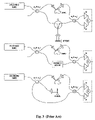
- Izatt and Rollin included, in their patent (U.S. Pat. No. 6,657,727), three more configurations as shown in FIG. 3 in which a transmissive sample is in the place of the circulator and the sample. They defined a transmissive sample as any sample illumination and collection geometry in which the illumination and collection optics occupy separate optical paths. Such designs have significant alignment issues and are not relevant to the invention being described where the illumination and collection optics occupy the same optical path.
- the key advantage of these prior configurations lies in the improvement of the optical power delivery efficiency to the detector(s), by properly selecting an optical power split ratio
- Izatt and Rollins Another issue with the classic Michelson interferometer ( FIG. 1 ) is that light from the reference arm is coupled back into the optical source, causing side effects that can impact the quality of the resulting image.
- Most of the configurations proposed by Izatt and Rollins address this issue as does the invention described herein.
- An issue not addressed by Izatt and Rollins configurations above is polarization fading, or loss of signal associated with mismatches between the polarization states of the light from the reference and sample arms. These mismatches are caused by birefringence and its fluctuations in the sample and reference arms, generally dominated by the birefringence in the optical fibers.
- FIG. 4 shows the approach of using two Faraday rotator mirrors at the end of the two arms of a standard Michelson fiber optic interferometer to eliminate polarization fading (Kersey, A. D. et al. “Polarization-insensitive fiber optic Michelson interferometer”, Electronics Letters, Volume: 27, Issue: 6, pages: 518–520, (1991)).
- the Faraday rotator and mirror enable birefringence compensation in a retraced fiber path for both the sample arm and the reference arm.
- optical splitter configuration is the same as the standard Michelson interferometer configuration of FIG. 1 .
- the invention described herein takes advantage of the polarization rotation caused by the Faraday rotators to increase the optical efficiency of the system by introducing a polarizing beam splitter in the source arm for coupling the light returning toward the source into a detector. This leads to an unbalanced optical efficiency assuming no birefringence in the sample and the use of a polarized source.
- An additional advantage of such a system is that the light being collected on the detector is linearly polarized, which is advantageous for spectral domain optical coherence tomography and reflectometry systems.
- the light is dispersed by a diffraction grating and collected by an array of detectors.
- the efficiency of the diffraction grating is generally polarization dependent, and thus can be made most efficient for linearly polarized light. As will be elaborated later, the present invention can meet such a requirement.
- PM fibers polarization-maintaining fibers.
- PDR polarization diversity receiver
- PM fibers have several issues associated with their two orthogonal polarization axes, which make them undesirable for commercial OCDR or OCT applications. These include variable optical dispersion, difficulties in maintaining high polarization extinction in the connection between two PM-fibers or between a PM-fiber and a polarization optical component, and high cost.
- FIG. 5 shows Sorin, et al.'s polarization independent optical coherence-domain reflectometry configuration (U.S. Pat. No. 5,202,745), where the light returning from the sample and reference arms is split into two orthogonal polarization modes with each mode being detected by a separate detector.
- a linear polarizer in the reference arm is adjusted to compensate for birefringence in the reference arm so as to equal signal powers on each detector in the detector arm in the absence of a signal from the test, or sample, arm.
- the problem with this approach is that the polarizer needs to be adjusted as the birefringence in the reference arm changes. As the birefringence in the non-PM reference arm fiber is strongly affected by temperature and stress, the system must be recalibrated with each use, and suffers from polarization drift during use.
- U.S. Pat. No. 6,385,358 disclosed a hybrid system involving the use of PM fibers, non-PM fibers and Faraday rotators.
- An important feature in this patent is the use of a 22.5° Faraday rotator in the beam path to enable a double path rotation of the polarized beam returned from reference arm so that the beam is equally split into two orthogonal polarization modes to interfere with the two corresponding but not necessarily equally split components of the beam from the sample arm, which are then detected by two detectors.
- the interference signal envelops from the two detectors the final signal is made independent of the birefringence of the sample arm in a similar way as in the case of a polarization diversity receiver.
- the dispersion property of the sample arm is also matched with that of the reference arm to eliminate the dispersion effects that degrade image resolution.
- arbitrary power split ration ⁇ /(1 ⁇ ) fiber coupler is also used to enable high efficiency optical power delivery to the detector. Considering that for medical applications, the portion of the fiber optic interacting with the patient must be changed for hygienic reasons, a non-PM fiber is incorporated into the sample arm to accommodate a disposable section at the end of the sample arm that interacts with the sample.
- a major disadvantage of the disclosed designs is that the system configuration is not simple at all, as it involves length matched PM fiber and non-PM fiber between the sample and references arms, their splices or connections and the use of a relatively large number of various optical components such as (PM or non-PM) fiber coupler, free space polarization beam splitter (PBS), various Faraday rotators of different rotation angles, and two photodetectors.
- PM or non-PM free space polarization beam splitter
- PBS free space polarization beam splitter
- the light beam needs to be expanded from a first fiber, collimated, passed through the Faraday rotator, and then refocused into the other fiber. All of these make the system both quite complicated and also expensive.
- the present invention addresses the above-mentioned problems and significantly improves on the prior art systems by effectively achieving high optical power delivery efficiency, polarization insensitivity and also dispersion matching, in a more compact, more robust, and also less expensive manner.
- the present invention discloses simple configurations of optical coherence domain reflectometry systems that are polarization insensitive and also highly efficient in terms of optical power delivery to the detector(s).
- a unique feature of the present invention is the combined use of a polarizing beam splitter with one or two polarization manipulator(s) that rotate the returned light wave polarization to an orthogonal direction.
- Such a combination provides the flexibility in interference fringe visibility control and the optimization of signal to noise ratio, as well as the possibility of polarization insensitivity, dispersion matching and optical output polarization control in an optical coherence domain reflectometry (OCDR) or optical coherence tomography (OCT) system.
- OCDR optical coherence domain reflectometry
- OCT optical coherence tomography
- an OCDR system (embodiment 1) includes a light source; a polarizing beam splitter having at least three ports; a non-polarizing beam splitter having at least three ports that is optically connected with the polarizing beam splitter; a sample arm leading to a sample that is optically connected to a first output port of the non-polarizing beam splitter; a reference arm leading to a reflector that is optically connected to a second output port of the non-polarizing beam splitter; one or two polarization manipulator(s) that rotate the returned polarization to an orthogonal direction, a detector that collects light combined by the non-polarizing beam splitter from the sample and reference arms, returned to the polarizing beam splitter in an orthogonal polarization state, and thus channeled by the polarizing beam splitter to the detector path for interference signal detection and processing.
- Another aspect of the present invention is to provide a method for performing optical coherence domain reflectometry comprising the steps of: guiding a light beam through a polarizing beam splitter and a non-polarizing beam splitter into a sample arm leading to a sample, and a reference arm leading to a reflector; rotating the polarization direction of returned light waves from said sample and said reflector to an orthogonal direction, followed by combining said returned light waves in said non-polarizing beam splitter, or combining returned light waves from said sample and said reference reflector in said non-polarizing beam splitter, and rotating the polarization direction of said returned light waves to an orthogonal direction; guiding said returned light waves to said polarizing beam splitter; and channeling at said polarizing beam splitter said combined and returned light waves having an orthogonal polarization state to a detector for interference signal extraction and processing.
- an OCDR system (embodiment 2) that includes a light source; a polarizing beam splitter having four ports, for receiving the light from said source through a first port, splitting the light into a second port and a third port, combining the light returned from the second port and third port, and channeling the combined light to a fourth port; a sample arm containing a polarization manipulator that rotates the returned light wave polarization to an orthogonal direction and a sample, wherein the sample arm is optically connected to the second port of the polarizing beam splitter; a reference arm containing a polarization manipulator that rotates the returned light wave polarization to an orthogonal direction and a reflector, wherein the reference arm is optically connected to the third port of the polarizing beam splitter; an analyzer for combining into a common polarization direction, two orthogonally polarized light waves, each from the sample and reference arms respectively, propagation-directionally combined and channeled by the polarizing
- Still another aspect of the present invention is to provide a method for performing optical coherence domain reflectometry comprising the steps of: guiding a light beam through a polarizing beam splitter into a sample arm containing a polarization manipulator that rotates the returned light wave polarization to an orthogonal direction and a sample, and a reference arm containing a polarization manipulator that rotates the returned light wave polarization to an orthogonal direction and a reflector; combining in the polarizing beam splitter, the returned light waves from the sample arm and the reference arm; channeling at the polarizing beam splitter, the combined and returned light waves having mutually orthogonal polarization states through the forth port to an analyzer and detector arm; projecting at the analyzer the two mutually orthogonally polarized light waves from the sample and reference arms respectively onto one (or two) polarization-passing-through-axis(es) of the analyzer; and collecting at the detector(s), the polarization-direction-combined interfering light wave(
- An object of the invention is to achieve high optical power delivery efficiency, polarization insensitivity as well as dispersion matching at the same time in a simple reflective-arms-based optical interferometer configuration, and this is realized through a combined use of a polarizing beam splitter with one or two polarization manipulator(s) that rotates the returned light wave polarization to an orthogonal direction.
- a second object of the invention is to achieve a predetermined or fixed polarization direction of the final combined interfering light waves at the detector or detection module so that a polarization sensitive detector or detection module can be used for such cases as spectral domain optical coherence tomography (SD-OCT).
- SD-OCT spectral domain optical coherence tomography
- a further object of the invention is to use non-PM fiber and non-PM fiber pigtailed fiber optic devices so that the cost of the system is much lower than PM fiber based counterparts.
- Another object of the present invention is to make it possible to adjust the polarization direction of the light wave projecting onto the sample without causing polarization fading resulting from the birefringence changes in the sample arm.
- Another object of the present invention is to make it possible to achieve optical path length delay or phase modulation using a fiber-wrapped PZT based transmissive optical delay line in the lead non-PM fiber portion of either the reference arm or the sample arm, without causing polarization fading resulting from the birefringence changes in the fiber portion of the reference or sample arm.
- Another object of the present invention is to also provide a configuration (embodiment 2) that can be easily converted between a two-detector-based balanced heterodyne detection scheme and a one detector based unbalanced detection scheme.
- Still another object of the invention is to further lower the cost of an OCDR system by using a thin film base analyzer to achieve the one detector based unbalanced detection scheme in embodiment 2.
- FIG. 1 shows a standard Michelson interferometer configuration used for OCDR or OCT.
- FIG. 2 shows 6 different interferometer configurations in which the optical power delivery efficiency to the detector(s) is improved as compared to the standard Michelson interferometer configuration.
- FIG. 3 shows some extensions of FIG. 2 in which the sample arm is transmissive in the sense that the illumination and collection optics geometry occupy separate optical paths
- FIG. 4 shows a prior art polarization insensitive Michelson interferometer configuration in which two 45° Faraday rotators are used at the end of the sample and reference arms.
- FIG. 5 shows another prior art polarization insensitive configuration called polarization diversity detection scheme.
- FIG. 6A shows a fiber optics version of a first embodiment of the presently invented interferometer configuration which is highly optical power efficient as well as polarization insensitive.
- FIG. 6B shows a bulk optics version of a first embodiment of the presently invented interferometer configuration which is highly optical power efficient as well as polarization insensitive.
- FIG. 6C shows a bulk optics version of a first embodiment of the presently invented interferometer configuration which uses only one polarization manipulator and is highly optical power efficient as well as polarization insensitive.
- FIG. 7A shows a fiber optics version of a second embodiment of the presently invented interferometer configuration which is highly optical power efficient as well as polarization insensitive.
- FIG. 7B shows a bulk optics version of a second embodiment of the presently invented interferometer configuration which is highly optical power efficient as well as polarization insensitive.
- FIG. 8 shows an exemplary detection module particularly useful for spectral domain OCT, which is often polarization sensitive hence preferring a predetermined polarization state of the interfered optical waves.
- the present invention is an optical coherence domain reflectometer (OCDR) system with a high optical power delivery efficiency and also fiber birefringence insensitivity that can use non-polarization maintaining (non-PM) fibers.
- OCDR optical coherence domain reflectometer
- the term optical coherence domain reflectometer (OCDR) is used to refer to a system that employs a light source in an optical interferometer to achieve high resolution with a large dynamic range in terms of resolving the light signals reflected or scattered from a sample.
- OCDR covers various modification of the basic technology, which, in addition to the traditional or conventional OCDR/OCT, also includes frequency-domain or Fourier-domain or spectral-domain optical coherence tomography.
- An important feature in the presently disclosed configuration of the invention is a combined use of a polarization beam splitter with one or two polarization manipulator(s) that rotate the returned light wave polarization to an orthogonal direction.
- a polarization beam splitter with one or two polarization manipulator(s) that rotate the returned light wave polarization to an orthogonal direction.
- FIG. 6A is a diagram of the OCDR system according to a first embodiment of the present invention.
- the light source 610 a introduces to the system 600 a a linearly polarized light wave either through a linearly polarized light source 610 a or by placing a linear polarizer (not shown) directly after an unpolarized source, wherein the linear polarizer can be an independent polarizer or the polarizing beam splitter as will be made clear below.
- the light source 610 a has a center wavelength within the optical spectrum range from ultra-through violet to near infrared.
- the light source 610 a is coupled through a short length of a non-PM fiber 612 a to the input port (port I) of a polarizing/polarization beam splitter (PBS) 614 a .
- PBS polarizing/polarization beam splitter
- the PBS 614 a may be based on a polarization beam splitter cube, in which case the light wave from a fiber needs to be collimated using, for example, a graded refractive index (GRIN) lens, and refocused into another fiber using, for example, another GRIN lens, if this is desired.
- GRIN graded refractive index
- the PBS may also be purely fiber optics based in which case polarization-maintaining (PM) fibers may be present.
- a polarization-maintaining (PM) fiber may have already been pig-tailed for the light source and such a PM fiber can be used to connect the light source 610 a to the PBS 614 a to maintain the polarization state.
- PM fiber pig-tailed polarization beam splitters are commercially available and their price is much less than that of a fiber pig-tailed optical circulator.
- the polarized light wave from the light source arm is already in the correct polarization state or direction so that except for the insertion loss introduced by the polarizing beam splitter 614 a , the input light power is substantially coupled to the output port (port II).
- a non-PM single mode fiber based polarization controller 611 a can be placed in front of the PBS 614 a to adjust the input polarization state to the desired direction.
- a non-PM fiber based polarization controller 611 a is preferred here, other types of polarization controller can also be used, for example, a bulk optical wave plate based polarization controller is also a choice.
- the polarized output from port II of the polarizing beam splitter 614 a is sent through a short length of non-PM fiber 616 a to a non-polarizing beam splitter or a non-PM fiber based coupler 618 a having a desired optical power split ratio
- the sample arm contains a certain length of a non-PM single mode fiber 624 a , an optical probe module 630 a and a sample 632 a .
- the non-PM single mode fiber 624 a can have any reasonable length as long as it approximately matches the length and dispersion property of the non-PM single mode fiber 640 a in the reference arm 622 a . It should be noted that here dispersion matching is desirable but not absolutely required. A preferred practice is to cut a single piece of a non-PM fiber into two pieces of substantially the same length with one for the sample arm and the other for the reference arm so that their dispersion property is also well matched.
- the optical probe module 630 a includes some light beam shaping and focusing elements, light beam bending or steering or scanning elements (not shown) such as pivoted scanning or dithering mirrors, and a polarization manipulator 634 a , wherein the polarization manipulator can be a Faraday rotator or a wave plate. It should be noted that in the optical probe module 630 a , the arrangement of various optical elements can be of any order or sequence.
- the polarization manipulator 634 a is placed at the end of the sample arm just in front of the sample, in practice, it may be more reasonable to place the polarization manipulator 634 a before any translational or mechanically movable components, and perhaps the easiest place to put it is at the end or tip of the fiber 624 a , as such a Faraday rotator tipped fiber piece is commercially available.
- the polarization state or direction of the returned light wave will be rotated by 90° after double-passing the non-reciprocal Faraday rotator 634 a to an orthogonal direction with respect to the polarization direction of the original forward-propagating light beam before it hits the Faraday rotator 634 a .
- any birefringence-induced polarization sensitivity or fading effect introduced to the sample arm light wave in the forward direction will be completely compensated for or cancelled when the light wave propagates in the backward direction.
- a polarization controller is included in the fiber section 624 a of the sample arm 620 a , a desired final polarization state of the light beam shining onto the sample can be selected to take full advantage of a biological sample if its light reflection or scattering property is polarization dependent and this polarization controlling will obviously not influence the final well-aligned interfering beam polarization directions from the sample arm and the reference arm (as will be discussed shortly) because of the polarization-insensitive fiber optic Michelson interferometer configuration. For example, one can maximize the final optical interference signal if for certain optical boundaries or interfaces the amount of reflected light is more intense in one polarization direction than the other or to examine the birefringence properties of the biological sample.
- the polarization manipulator may be selected in such a way that when it is combined with the birefringence of the biological sample, a substantially 90° polarization direction rotation for the returned light wave with respect to the original forward propagating light wave is realized.
- a polarization manipulator can be either a wave plate or a combination of a polarization controller and a wave plate, wherein the polarization controller can select a desired polarization direction with respect to the wave plate and the biological sample, and the wave plate can combine its birefringence with that of the biological sample to provide a net quarter wave plate effect.
- the optical power split ratio of the non-polarizing beam splitter or the non-PM fiber based coupler 618 a is polarization-independent, which is generally the case.
- the statement should not exclude the case of a non-PM fiber based coupler that may be slightly polarization sensitive due to imperfection in the fabrication of the coupler and in which case, the attenuation for the returned light wave may be slightly different from that for the forwarding propagating light wave.
- non-PM fiber 650 a is used to guide the light wave to a detector (or a light detection module) 652 a such that the polarization state is not altered by the short length of the non-PM fiber 650 a , the polarization state (or direction) of the light wave reaching the detector (or light detection module) 652 a will be fixed and predetermined.
- this fixed and predetermined polarization state of the arriving light wave is not critical, it is actually very critical for the spectral-domain optical coherence tomography (SD-OCT) detection scheme since in such a system, the grating used to disperse the constituent wavelength components of the broadband optical signal is generally sensitive to the polarization direction of the input beam and hence a fixed or predetermined polarization direction of the input beam to the grating will be extremely beneficial.
- SD-OCT spectral-domain optical coherence tomography
- the reference arm there should preferably be a non-PM single mode fiber 640 a that is approximately matched in length and dispersion property with the non-PM single mode fiber 624 a in the sample arm.
- the optical delay line 642 a is incorporated in the reference arm 622 a and this reference delay line 642 a may be a transmissive one to be implemented in the fiber section 622 a which can be achieved by wrapping a certain length of optical fiber around a piezoelectric cylinder.
- this reference delay line 642 a may be a transmissive one to be implemented in the fiber section 622 a which can be achieved by wrapping a certain length of optical fiber around a piezoelectric cylinder.
- such an optical fiber wrapped PZT based optical delay line will generally introduce a substantial amount of polarization fading as a result of the birefringence change during the optical path length scanning or optical phase modulation process, but with the presently invented configuration, this is no longer an issue any more because of the polarization insensitivity nature and hence it might be advantageous to use such a fiber wrapped PZT based optical path length delay line.
- the optical delay line can also be located in the sample arm or both arms may have an optical delay line with the two operating in a push-and-pull mode or in any other manners as desired such as with one modulating the path length to achieve a depth scan and the other modulating the optical phase to obtain a high carrier frequency for the interference signal.
- an independent optical delay line may be used after the fiber 640 a and a good example is a grating based phase control optical delay line as disclosed in U.S. Pat. Nos. 6,111,645 and 6,282,011.
- the overall optical path length for the reference arm 622 a should roughly match that of the sample arm 620 a and this can be achieved by letting the reference light wave traveling through some free space and/or some other optical elements.
- the requirement for the scan range of the optical delay line 642 a can be lowered and data acquisition time for one depth scan can thus be reduced to a minimum.
- the reference arm 622 a may also contain some light collimating and/or focusing optical elements 644 a , and there should be a polarization manipulator such as a 45° Faraday rotator 646 a and a mirror 648 a to reflect the reference light wave back to the non-polarizing beam splitter or the non-PM fiber coupler 618 a .
- a polarization manipulator such as a 45° Faraday rotator 646 a and a mirror 648 a to reflect the reference light wave back to the non-polarizing beam splitter or the non-PM fiber coupler 618 a .
- the position of the 45° Faraday rotator 646 a is preferably at the end of the reference arm 622 a and right in front of the mirror 648 a so that polarization fading caused by any birefringence or birefringence fluctuations introduced by all the optical elements prior to the Faraday rotator 646 a in the reference arm 622 a can be completely compensated for and hence cancelled.
- the 45° Faraday rotator 646 a can be placed anywhere between the end of the non-PM fiber 640 a and the mirror 648 a .
- the reference arm fiber 640 a may be selected to be longer than the sample arm fiber 624 a such that the overall optical path length between the sample arm 624 a and the reference arm 622 a is roughly matched.
- the light wave returned from the mirror 648 a is collected by the same optical element(s) 644 a & 646 a and is directed back through the same non-PM optical fiber 640 a in the reference arm 622 a to the non-polarizing beam splitter or the non-PM fiber coupler 618 a .
- the polarization state or direction of the returned light wave will be rotated by 90° after double-passing the non-reciprocal Faraday rotator 646 a to an orthogonal direction with respect to the polarization direction of the original forward-propagating light wave in the reference arm 622 a before it hits the Faraday rotator.
- any birefringence-induced polarization sensitivity or fading effect introduced to the reference arm light wave in the forward direction will be completely compensated for or cancelled when the light wave propagates in the backward direction.
- 1 ⁇ the optical power efficiency
- a low optical power efficiency for the reference arm 622 a is desirable as long as the photon shot noise from the reference arm 622 a is above the detector circuit noise.
- a non-polarizing beam splitter or a fiber coupler 618 a that couples as much light as possible to the sample arm 620 a , while leaving enough light from the reference arm 622 a to maintain the shot noise just above detector circuit noise.
- a short length of a non-PM fiber 650 a is used to guide the returned interfering light waves to a detector (or a light detection module) 652 a such that the polarization state is not altered by the short length of the non-PM fiber 650 a , the polarization state or direction of the returned light waves reaching the detector (or light detection module) 652 a will be fixed and predetermined. As has already been pointed out; this is especially beneficial to spectral domain optical coherence tomography (SD-OCT).
- SD-OCT spectral domain optical coherence tomography
- the detector or light detection module 652 a may be directly placed or bonded next to the PBS 614 a and in such a case, the requirement to focus the returned interfered light beam into a single mode fiber may be eliminated as a photodetector generally has a relative large light sensitive area and this may save cost for the systems.
- FIG. 6A a fiber optics version of the first embodiment of the present invention is illustrated; a bulk optics based free space version is obviously a natural extension of the invention.
- the bulk optics version may provide other advantages. For example, with bulk optics, the two 45° Faraday rotators may be replaced by two quarter wave plates which may be less expensive, and the need to expand and collimate a light beam from a single mode fiber, and to refocus the expanded beam back into another single mode optical fiber, may be eliminated, which may also save cost for the system.
- FIG. 6B shows a bulk optics version of the first embodiment of the present invention.
- the light source 610 b can be either a fiber pigtailed or non-fiber-pigtailed but collimated light source. If it is fiber pig-tailed, a collimating lens needs to be used to collimate the output beam.
- the light source can be either originally linearly polarized or externally linearly polarized by placing a linear polarizer (not shown) directly after an unpolarized source or by using the polarizing beam splitter 614 b to polarize it.
- the light source 610 b is directed through a free space 612 b to the input port (port I) of a polarizing/polarization beam splitter (PBS) cube 614 b . It is desirable that the input linearly polarized light wave is already in the correct polarization state or direction and hence the optical power is substantially transmitted to the output port (port II).
- PBS polarizing/polarization beam splitter
- the light wave from port II of the polarizing beam splitter 614 b is directed through a free space 616 b to a non-polarizing beam splitter (NPBS) 618 b with a desired optical power split ratio of
- the light wave in the sample arm travels through a free space optical path 624 b to an optical probe module 630 b , in which the light beam is scanned and focused onto a sample 632 b .
- a polarization manipulator such as a quarter wave plate or a 45° Faraday rotator 634 b is placed in the probe module 630 b to enable the polarization rotation of the returned light wave by 90°. Note that when a quarter wave plate is used, although it may be cheaper than a 45° Faraday rotator, the projected light wave onto the sample will be circularly polarized instead of linearly polarized as in the case of a 45° Faraday rotator.
- a quarter wave plate will not deliver a linearly polarized light wave to the sample 632 b as in the case of a 45° Faraday rotator, where a free space based polarization controller may be inserted in the sample arm path 624 b to deliver a desired polarization direction to the sample 632 b as in the fiber optics version case.
- the returned light wave from the sample 632 b is collected by the probe module 630 b , directed back to the NPBS 618 b , where it is further split with a larger optical power splitting percentage of a back towards the PBS 614 b.
- the use of a quarter wave plate or a 45° Faraday rotator 646 b will rotate the polarization direction of the returned light wave by 90°.
- a quarter wave plate can always be used anywhere in the reference arm, although a more expensive 45° Faraday rotator can also be used.
- a dispersion matching optical element can also be used in the reference arm. Similar to the fiber optics version case, the optical delay line 642 b is preferably incorporated in the reference arm 622 b.
- the light wave returned from the reference mirror 648 b is directed back through the same free space optical path 640 b to the non-polarizing beam splitter NPBS 618 b and is split with a smaller optical power percentage of (1 ⁇ ) towards the polarizing beam splitter PBS 614 b.
- the polarization direction of the returned light waves from both the sample arm and the reference arm have been rotated by 90° with respect to the original forward traveling light wave, basically all of the two returned light waves will now be channeled to port III of the polarizing beam splitter 614 b .
- the polarization state or direction of the returned light waves reaching the detector (or light detection module) 652 b will be fixed and predetermined.
- a detector or a detection module 652 b can be used to collect the two interfering light waves to convert the interfered optical power into an electrical signal for further processing.
- the optical path 650 b can be a free space path and can be shortened to a minimum by placing the detector or detection module 652 b next to the PBS 614 b .
- a fiber pig-tailed detector or detection module may be used and in such a case the optical path 650 b may represent a short length of optic fiber and wherein there will be a need to focus the free space light beam into such an optical fiber.
- FIG. 6C shows another free space optics version of an implementation of embodiment 1.
- FIG. 6C uses only one polarization manipulator 670 c in the common optical path portion between the PBS 614 c and the NPBS 618 c to rotate the polarization of the two returned light waves from the sample arm and the reference arm respectively to an orthogonal direction. Similar to the argument of FIG. 6B , as the retuned light waves to the PBS 614 c have an orthogonal polarization, they will be completely channeled to port III and hence to the detector 652 c with a fixed or predetermined polarization direction.
- the polarization manipulator 670 c can be either a quarter wave plate or a 45° Faraday rotator.
- a quarter wave plate is preferred here due to its lower price and in such a case, the light wave to the right side of the quarter wave plate will be circularly polarized and will be further split by the NPBS 618 c into the sample arm and the reference arm with a desired optical power split ratio.
- the light wave to the right side of the Faraday rotator will be linearly polarized but with an azimuth orientation that is 45° with respect to the incident light wave on the left side of the 45° Faraday rotator.
- Such a linearly polarized light wave will be further split into the sample arm and the reference arm by the NPBS 618 c with a desired optical power split ratio.
- a free space based polarization controller may be inserted in the sample arm path 624 c to deliver a desired polarization direction to the sample 632 c as in the fiber optics version case.
- the returned light waves Upon reflection from the biological sample and the reference mirror, the returned light waves will be further split by the NPBS 618 c toward the polarization manipulator 670 c . Due to the fact that the light wave propagating toward the PBS 614 c from the sample arm will have transmitted through the NPBS 618 c twice, whereas the light wave propagating toward the PBS 614 c from the reference arm will have been reflected twice by NPBS 618 c , the optical power delivery efficiency can hence be made very high by splitting most of the optical power to the sample arm.
- FIG. 6C It should be understood that the rest of the embodiment of FIG. 6C is similar to what has been discussed for FIG. 6A and FIG. 6B and hence will not be repeated here. Note that the embodiment of FIG. 6C may be especially advantageous for free space based SD-OCT system such as SD-OCT microscopes as the cost is even lower than that of FIG. 6B . It should also be understood that a combination of various features of FIG. 6A , FIG. 6B and FIG. 6C can be selected to suit various applications.
- FIG. 7A is a diagram of the OCDR system according to a second embodiment of the present invention.
- the light source 710 a introduces to the system 700 a a linear polarized light wave either through a linearly polarized light source 710 a or by placing a linear polarizer (not shown) directly after an unpolarized source.
- the light source 710 a has a center wavelength within the optical spectrum range from ultra-violet to near infrared.
- the light source 710 a is coupled through a short length of a non-PM fiber 712 a to the input port (port I) of a polarizing/polarization beam splitter (PBS) 714 a .
- PBS polarizing/polarization beam splitter
- the polarization direction of the input light wave of embodiment 2 is neither in the vertical nor in the horizontal direction but is rather selected to lie in a direction in between these two axis.
- the polarization directions of the two light waves in the sample and reference arms are orthogonal or perpendicular with respect to each other.
- the PBS 714 a may be based on a polarization beam splitter cube, in which case the light wave from a fiber needs to be collimated using, for example, a graded refractive index (GRIN) lens and refocused into another fiber using, for example, another GRIN lens, if this is desired.
- GRIN graded refractive index
- the PBS 714 a may also be purely fiber optics based in which case polarization-maintaining (PM) fibers may be present.
- a polarization-maintaining (PM) fiber may have already been pig-tailed for the light source and such a PM fiber can be used to connect the light source 710 a to the PBS 714 a to maintain the polarization state.
- PM fiber pig-tailed polarization beam splitters are commercially available and their price is much less than that of a fiber pig-tailed optical circulator. Hence such fiber pigtailed PBS may be used directly.
- the polarized light wave from the light source arm is already in the desired polarization state or direction to enable a desired percentage of the input optical power to the sample and reference arms respectively.
- the PBS 714 a of FIG. 7A also serves the purpose of the fiber coupler 618 a of FIG. 6A , i.e. to split the input optical power at a desired ratio into the sample and reference arms. If the input polarization state is not in the desired direction, a non-PM single mode fiber based polarization controller 711 a can be placed in front of the PBS 714 a to adjust the input polarization state to the desired direction.
- non-PM fiber based polarization controller 711 a is preferred here, other types of polarization controller can also be used, for example, a bulk optical wave plate based polarization controller is also a choice.
- PBS polarizing beam splitter
- the polarized output from port II of the polarizing beam splitter 714 a is sent through a non-PM single mode fiber 724 a and an optical probe module 730 a to a sample 732 a .
- the non-PM single mode fiber 724 a can have any reasonable length as long as it approximately matches the length and dispersion property of the non-PM single mode fiber 740 a in the reference arm 722 a . It should be noted that here dispersion matching is desirable but not absolutely required. A preferred practice is to cut a single piece of a non-PM fiber into two pieces of substantially the same length with one for the sample arm and the other for the reference arm so that their dispersion property is also well matched.
- the optical probe module 730 a includes some light beam shaping and focusing elements, light beam bending or steering or scanning elements (not shown) such as pivoted scanning or dithering mirrors, and a polarization manipulator such as a 45° Faraday rotator or a quarter wave plate 734 a . It should be noted that in the optical probe module 730 a , the arrangement of various optical elements can be of any order or sequence.
- a Faraday rotator 734 a is placed at the end of the sample arm just in front of the sample, in practice, it may be more reasonable to place the Faraday rotator 734 a before any translational or mechanically movable components, and perhaps the easiest place to put it is at the end or tip of the fiber 724 a as such a Faraday rotator tipped fiber piece is commercially available.
- any birefringence-induced polarization sensitivity or fading effect introduced to the sample arm light wave in the forward direction will be completely compensated for or cancelled when the light wave propagates in the backward direction.
- a polarization controller is included in the fiber section 724 a of the sample arm 720 a , a desired final polarization state of the light beam shining onto the sample can be selected to take full advantage of a biological sample if its light reflection or scattering property is polarization dependent and this polarization controlling will obviously not influence the final polarization direction of the returned light wave from the sample arm. For example, one can maximize the final optical interference signal if, for certain optical boundaries or interfaces, the amount of reflected light is more intense in one polarization direction than the other or to examine the birefringence properties of a biological sample using this approach.
- the polarization manipulator may be selected in such a way that when it is combined with the birefringence of the biological sample, a substantially 90° polarization direction rotation for the returned light wave with respect to the original forward propagating light wave is realized.
- a polarization manipulator can be either a single wave plate or a combination of a polarization controller and a wave plate, wherein the polarization controller can select a desired polarization direction with respect to the wave plate and the biological sample, and the wave plate can combine its birefringence with that of the biological sample to provide a net quarter wave plate effect.
- the wave will propagate to a polarization manipulator such as a Faraday rotator or a quarter wave plate 746 a and a mirror 748 a through a non-PM single mode fiber 740 a that is approximately matched in length and dispersion property with the non-PM single mode fiber 724 a in the sample arm 720 a .
- a polarization manipulator such as a Faraday rotator or a quarter wave plate 746 a and a mirror 748 a
- the optical delay line 742 a for depth scanning is incorporated in the reference arm 722 a .
- This reference delay line 742 a may be a transmissive one to be implemented in the fiber section 722 a , which can be achieved by wrapping a certain length of optical fiber around a piezoelectric stretcher.
- a standard polarization sensitive OCT configuration such as those shown in FIG. 1 and FIG. 2
- such an optical fiber wrapped PZT based optical delay line will generally introduce a substantial amount of polarization fading as a result of the birefringence change during the optical path length scanning or optical phase modulation process, but with the presently invented configuration, this is no longer an issue because of the polarization insensitivity nature and hence it might be advantageous to use such a fiber wrapped PZT based optical path length delay line.
- the optical delay line can also be located in the sample arm or both arms may have an optical delay line with the two operating in a push-and-pull mode or in any other manners as desired such as with one modulating the path length to achieve a depth scan and the other modulating the optical phase to obtain a high carrier frequency for the interference signal.
- an independent optical delay line may be used after the fiber 740 a and a good example is a grating based phase control optical delay line as disclosed in U.S. Pat. Nos. 6,111,645 and 6,282,011.
- the overall optical path length for the reference arm 722 a should roughly match that of the sample arm 720 a and this can be achieved by letting the reference light wave traveling through some free space and/or some other optical elements.
- the requirement for the scan range of the optical delay line 742 a can be lowered and data acquisition time for one depth scan can thus be reduced to a minimum.
- the reference arm 722 a may also contain some light beam shaping and/or focusing optical elements 744 a in addition to the polarization manipulator such as a 45° Faraday rotator 746 a and the mirror 748 a .
- the position of the 45° Faraday rotator 746 a is preferably at the end of the reference arm 722 a and right in front of the mirror 748 a so that polarization fading caused by any birefringence or birefringence fluctuations introduced by all the optical elements prior to the Faraday rotator 746 a in the reference arm 722 a can be completely compensated for and hence cancelled.
- the 45° Faraday rotator 746 a can be placed anywhere between the end of the non-PM fiber 740 a and the mirror 748 a . It is perhaps even more economic to directly use a mirrored 45° Faraday rotator with a non-PM fiber pig-tail as such a device is now commercially available, and in such a case, the reference arm fiber 740 a may be selected to be longer than the sample arm fiber 724 a such that the overall optical path length between the sample arm 720 a and the reference arm 722 a is roughly matched.
- the light wave returned from the mirror 748 a is collected by the same optical element(s) 744 a & 746 a and is directed back through the same non-PM optical fiber 740 a in the reference arm 722 a to the PBS 714 a .
- the polarization state or direction of the returned light wave will be rotated by 90° after double-passing the non-reciprocal Faraday rotator 746 a to an orthogonal direction with respect to the polarization direction of the original forward-propagating light wave in the reference arm 722 a before it hits the Faraday rotator 746 a .
- any birefringence-induced polarization sensitivity or fading effect introduced to the reference arm light wave in the forward direction will be completely compensated for or cancelled when the light wave propagates in the backward direction.
- a major difference here is that the polarization directions of the reference-arm-returned-light wave and the sample-arm-returned-light wave are orthogonal or perpendicular to each other. As a result, if one directly puts a detector to detect these two waves, there will be no interference signals as is well known to those skilled in the art.
- the first one is to arrange another polarizing/polarization beam splitter 752 a in such a way that its azimuth orientation is substantially at 45° with respect to that of the first polarizing beam splitter 714 a .
- a balanced heterodyne detection scheme can be realized as shown in FIG. 7A .
- the second polarizing beam splitter 752 a can actually be glued or bonded to the first polarizing beam splitter 714 a so that they become a rigid solid module together with the two detectors D 1 and D 2 .
- the above statements should not exclude the use of a short length of a non-PM fiber 750 a between the first PBS 714 a and the second PBS 752 a , as long as the polarization state is not altered by the short length of the non-PM fiber 750 a .
- the statements also should not exclude the use of a PM fiber between the first PBS 714 a and the second PBS 752 a , and the reason for this is that a PM fiber pig-tailed PBS with four ports are commercially available and hence can be readily used.
- the second approach to extract the interference signal from two orthogonally polarized optical light waves is to use a simple analyzer together with only one detector.
- the second polarizing beam splitter can be azimuthally oriented in such a way that an enhanced interference fringe visibility is achieved together with shot noise limited detection as has been discussed before.
- the orientation direction of the second PBS 752 a can be chosen such that while a smaller amount of the optical wave from the reference arm is projected to the polarization-passing-through-axis of the analyzer and a lager amount of the optical wave from the sample arm is projected to the same polarization-passing-through-axis of the analyzer, the amount of optical power from the reference wave also gives a photon shot noise from the reference arm that is just above the detector thermal noise.
- the second PBS 752 a now acts as an unbalanced beam combiner with a non-50/50 power split ratio
- a detector e.g. D 1
- the thin film analyzer 754 a it might be even more economical to fix or bond a detector (e.g. D 1 ) and the thin film analyzer 754 a to the first PBS 714 a and in such a case, the requirement to focus the returned light waves into a single mode fiber can be eliminated as a photodetector generally has a relative large light sensitive area and this may save cost for the systems.
- the polarization state or direction of the returned light waves reaching the detector (or light detection module) D 1 will be fixed and predetermined.
- this is especially beneficial to spectral domain optical coherence tomography (SD-OCT), also referred to in the literature as frequency or Fourier domain optical coherence tomography, since in such a system, the grating used to disperse the constituent wavelength components of the broadband optical signal is generally sensitive to the polarization direction of the input beam and hence a fixed or predetermined polarization direction of the input beam to the grating will be extremely beneficial.
- SD-OCT spectral domain optical coherence tomography
- the grating used to disperse the constituent wavelength components of the broadband optical signal is generally sensitive to the polarization direction of the input beam and hence a fixed or predetermined polarization direction of the input beam to the grating will be extremely beneficial.
- the bulk optics version may provide other advantages.
- the two 45° Faraday rotators may be replaced by two quarter wave plates, and the need to expand and collimate a light beam from a single mode fiber, and to refocus the expanded/collimated beam back into another single mode optical fiber, may be eliminated, which may save cost for the system.
- FIG. 7B shows a bulk optics version of the second embodiment of the present invention.
- the light source 710 b is preferably a non-fiber-pigtailed, collimated light source such as one with a TO can package, but can be fiber pig-tailed, in which case a collimating lens needs to be used to collimate the output beam.
- the light source can be either originally linearly polarized or externally linearly polarized by placing a linear polarizer 713 b directly after an unpolarized source.
- the light source 710 b is directed through a free space 712 b to the input port (port I) of a polarizing/polarization beam splitter (PBS) cube 714 b . It is assumed that the input linearly polarized light wave is already in a desired polarization state or direction such that a large portion of input optical power is split into the sample arm 720 b via port II of the PBS cube 714 b and a small portion of the input optical power is split into the reference arm 722 b via port III of the PBS cube 714 b.
- PBS polarizing/polarization beam splitter
- the light wave in the sample arm travels through a free space optical path 724 b to an optical probe module 730 b , in which the light beam is scanned and focused onto a sample 732 b .
- a quarter wave plate or a 45° Faraday rotator 734 b is placed in the probe module 730 b to enable the polarization rotation of the returned light wave by 90°. Note that when a quarter wave plate is used, although it may be cheaper than a 45° Faraday rotator, the projected light wave onto the sample 732 b will be circularly polarized instead of linearly polarized as in the case of a 45° Faraday rotator.
- a quarter wave plate will not deliver a linearly polarized light wave to the sample 732 b as in the case of a 45° Faraday rotator where a free space based polarization controller may be inserted in the sample arm path 720 b to deliver a desired polarization direction to the sample 732 b as in the fiber optics version case.
- the returned light wave from the sample 732 b after being collected by the probe module 730 b , and directed back to the PBS 714 b , will have its polarization direction rotated by 90° with respect to the original forward propagating beam.
- the returned sample wave will now be totally directed to port IV of the PBS 714 b.
- a quarter wave plate or a 45° Faraday rotator 746 b will rotate the polarization direction of the returned reference light wave by 90°. Since the mirror 748 b does not need a preferred polarization state and there is generally no birefringence change for a light wave traveling in free space, a quarter wave plate can always be used anywhere in the reference arm 722 b . In addition to an approximate optical path length matching between the sample arm and the reference arm, a dispersion matching optical element can also be used in the reference arm 722 b . Similar to the fiber optics version case, the optical delay line 742 b is preferably incorporated in the reference arm 722 b.
- the light wave returned from the reference mirror 748 b is directed back through the same free space optical path 740 b to the polarizing beam splitter PBS 714 b . Now that its polarization direction has been rotated by 90° with respect to the original forward propagating beam, as is well known to those skilled in the art, the returned reference wave will now be totally directed to port IV of the PBS 714 b.
- the two waves exiting port IV of the PBS 714 b have orthogonal polarization and in order to extract the interference signal, an analyzer or another PBS needs to be used. While balanced heterodyne detection can be realized using a 45° azimuthally oriented PBS 752 b together with two detectors, a less expensive approach is to use a thin film based analyzer 754 b with one detector (See insert, FIG. 7B ).
- the polarization state or direction of the interfering light waves reaching the detector(s) will be in the polarization-passing-through-direction of the analyzer and hence is fixed and predetermined by the analyzer 754 b or the second PBS 752 b , which as mentioned before, is beneficial to SD-OCT detection scheme.
- the optical path 750 b can be a free space path and can be shortened to a minimum by placing the analyzer 754 b or the second PBS 752 b together with the detector(s) next to the PBS 714 b .
- a fiber pig-tailed detector or detection module may also be used and in such a case there will be a need to focus the free space light beam into such an optical fiber.
- FIG. 7A As has been discussed for embodiment 1, it should be understood that a combination of various features of FIG. 7A , and FIG. 7B can be selected to suit various applications.
- a fiber based sample arm for easy and flexible light delivery to a biological sample together with a 45° Faraday rotator to render the sample arm insensitive to birefringence fluctuations and, to save costs, the reference arm can be a free-space optics based configuration with a quarter wave plate.
- the configurations of the present invention are relatively simple and hence of relatively low cost.
- the main difference in terms of optical components used include a polarizing beam splitter and one or two polarization manupulator(s).
- a polarization insensitive fiber pig-tailed optical circulator contains a number of more optical elements in addition to the use of a polarizing beam splitter and some Faraday rotators, the configurations of the present invention will hence cost less than a configuration that include a polarization insensitive fiber pig-tailed optical circulator.
- the present invention is particularly beneficial for application in spectral domain OCT (SD-OCT), as in such a case it is preferred that the polarization state of the interfering light waves sent to the detection module be fixed or predetermined as the module contains a polarization dependent optical element such as a grating.
- FIG. 8 shows an example of such a SD-OCT detection module. Assuming that the interfered light wave is guided in an optical fiber 810 , a lens 820 can be used to collimate the beam and project it onto a blazed reflection grating 830 . It is preferable that the optical fiber be short to minimize polarization effects in the fiber.
- the grating 830 will disperse the various wavelength components of the light source into parallel beams of different diffraction angles. It should be noted that while a blazed reflection grating has been shown here, other optical dispersing elements can be used to achieve the same goal. Some examples include a transmission grating, an arrayed waveguide grating, and a prism. Lens 840 can be used to focus the various beams of different diffraction angles and hence different wavelength components onto a detector array 850 . Due to the fact that a fixed optical path length difference between a reference reflector and a sample reflection site will correspond to different optical phase delays for different wavelength components, the various wavelength components will hence give rise to alternating constructive and destructive interference fringe on the detector array 850 .
- the optical delay line may be used to achieve a phase shift modulation in order to determine the relative phase of the light returning from the reference and sample arm.
- a phase shift modulation in order to determine the relative phase of the light returning from the reference and sample arm.
- Vakhtin et al. Vakhtin, Andrei B. et al. (2003) “Differential spectral interferometry: an imaging technique for biomedical applications”, Optics Letters, Volume 28, Issue 15, 1332–1334.
- Fercher U.S. Pat. No. 6,377,349
Abstract
Description
and neglecting loss in the splitter, the attenuation by the beam splitter or the fiber coupler (BS/FC) to both the sample optical wave and the reference optical wave is the same and is equal to α(1−α), the only difference is that for one wave it will propagate straight-through the BS/FC first with an attenuation by a factor of α and then crossover the BS/FC with a further attenuation by a factor of (1−α), whereas for the other wave, it will crossover the BS/FC first with an attenuation by a factor of (1−α) and then propagate straight-through the BS/FC with a further attenuation by a factor of α. It is well known to those skilled in the art that for such a configuration, the most efficient power splitting ratio is 50/50, where
simply because the function α(1−α) has its maximum value when α=0.5. For example, with a 50/50 power split ratio, for either the sample arm or the reference arm, the optical power is firstly attenuated at the BS/FC by 50% from the light source to the sample or reference arm and then further attenuated by 50% from the sample or reference arm to the detector, which leads to a total overall power attenuation factor of 50%×50%=25% for both arms. If the BS/FC power split ratio is 90/10, then for the reference and the sample arm respectively, the total overall power attenuation factor by the BS/FC will be 90%×10% and 10%×90%, which is the same and is equal to only 9%.
instead of 50/50 that is optimized for optical power efficient high SNR detection by directing most of the original optical power to the
can be properly chosen for either the two detector based balanced
Izatt and Rollin stated that for the configuration shown in FIGS. 2Ci, the SNR can be improved over that of
(for either the prior and/or the post fiber coupler).
(say, for example,
so that most of the light (for example α=at least 70% and preferably 90%) is coupled to the
such that most of the light is coupled to the
and the optical delivery efficiency is similar to that of FIG. 2Aii, but the present invention is Michelson interferometer based and it makes the system insensitive to polarization fading. It should be pointed out that there is no absolute need to use a cube based second
where M is an integer and λ is the central wavelength of the light source. Hence it should be understood that the 45° Faraday rotator or quarter wave plate can be replaced accordingly as long as the final polarization direction of the returned light wave is in the orthogonal direction with respect to the original forward propagating light wave. Furthermore, even if the birefringence property of the light path in either the sample arm or the reference arm may change or fluctuate, as long as such a change can be monitored and compensated dynamically, one could also achieve the same goal of rotating the returned light wave polarization to the orthogonal direction and a good example is a dynamically controllable quarter-wave plate (QWP), such a QWP can be dynamically tuned in response to changes or fluctuations in the either the sample arm or the reference arm to ensure a total returned polarization direction rotation by 90°.
- U.S. Pat. No. 5,202,745, Sorin, et al. “Polarization independent optical coherence-domain reflectometry”
- U.S. Pat. No. 5,321,501, Swanson, et al. “Method and apparatus for optical imaging with means for controlling the longitudinal range of the sample”
- U.S. Pat. No. 5,459,570, Swanson, et al. “Method and apparatus for performing optical measurements”
- U.S. Pat. No. 6,111,645, Tearney, et al. “Grating based phase control optical delay line”
- U.S. Pat. No. 6,282,011, Tearney, et al. “Grating based phase control optical delay line”
- U.S. Pat. No. 6,377,349, Fercher, “Arrangement for spectral interferometric optical tomography and surface profile measurement”
- U.S. Pat. No. 6,385,358, Everett M. et al. “Birefringence insensitive optical coherence domain reflectometry system”
- U.S. Pat. No. 6,657,727, Izatt, et al. “Interferometers for optical coherence domain reflectometry and optical coherence tomography using nonreciprocal optical elements”
- Fujimoto, J. G. et al. “Optical Coherence Tomography: An Emerging Technology for Biomedical Imaging and Optical Biopsy” Neoplasia (2000) 2, 9–25;
- Fujimoto, J. G. “Optical coherence tomography for ultrahigh resolution in vivo imaging.” Nat Biotechnol 21(11): 1361–7, (2003)
- Huang, D., E. A. Swanson, et al. (1991). “Optical coherence tomography.” Science 254 (5035): 1178–81
- Kersey, A. D. et al. “Polarization-insensitive fiber optic Michelson interferometer”, Electronics Letters, Volume: 27, Issue: 6, pages: 518–520, (1991)
- Kobayashi et al, “Polarization-Independent Interferometric Optical-Time-Domain Reflectometer”, 1991, J. Lightwave Tech. 9(5):623–628
- Rollins A. M. et al. “Emerging Clinical Applications of Optical Coherence Tomography”Optics and Photonics News, Volume 13, Issue 4, 36–41, April 2002;
- Rollins, A. M. and Izatt, J. A. “Optimal interferometer designs for optical coherence tomography” Optics Letters, Vol. 24 Issue 21 Page 1484 (1999)
- Schmitt, J. M. “Optical coherence tomography (OCT): a review”, IEEE Journal of Selected Topics in Quantum Electronics, Volume: 5, Issue: 4, Year: July/August 1999 pages:1205–1215;
- Swanson E. A. et al. “Optical coherence tomography, Principles, instrumentation, and biological applications” Biomedical Optical Instrumentation and Laser-Assisted Biotechnology, A. M. Verga Scheggi et al. (eds.) pages: 291–303, 1996 Kluwer Academic Pulishers, Printed in the Netherlands
- Vakhtin, Andrei B et al. “Differential spectral interferometry: an imaging technique for biomedical applications”, 2003, Optics Letters, 28(15): 1332–1334
- Youngquist et al., “Optical Coherence-Domain Reflectometry: A New Optical Evaluation Technique”, 1987, Optics Letters 12(3):158–160
Claims (69)
Priority Applications (2)
| Application Number | Priority Date | Filing Date | Title |
|---|---|---|---|
| US10/811,748 US7126693B2 (en) | 2004-03-29 | 2004-03-29 | Simple high efficiency optical coherence domain reflectometer design |
| PCT/US2005/010471 WO2005095918A2 (en) | 2004-03-29 | 2005-03-29 | Simple high efficiency optical coherence domain reflectometer design |
Applications Claiming Priority (1)
| Application Number | Priority Date | Filing Date | Title |
|---|---|---|---|
| US10/811,748 US7126693B2 (en) | 2004-03-29 | 2004-03-29 | Simple high efficiency optical coherence domain reflectometer design |
Publications (2)
| Publication Number | Publication Date |
|---|---|
| US20050213103A1 US20050213103A1 (en) | 2005-09-29 |
| US7126693B2 true US7126693B2 (en) | 2006-10-24 |
Family
ID=34967182
Family Applications (1)
| Application Number | Title | Priority Date | Filing Date |
|---|---|---|---|
| US10/811,748 Active - Reinstated 2025-02-04 US7126693B2 (en) | 2004-03-29 | 2004-03-29 | Simple high efficiency optical coherence domain reflectometer design |
Country Status (2)
| Country | Link |
|---|---|
| US (1) | US7126693B2 (en) |
| WO (1) | WO2005095918A2 (en) |
Cited By (78)
| Publication number | Priority date | Publication date | Assignee | Title |
|---|---|---|---|---|
| US20060077395A1 (en) * | 2004-10-13 | 2006-04-13 | Kabushiki Kaisha Topcon | Optical image measuring apparatus and optical image measuring method |
| US20060109477A1 (en) * | 2004-11-19 | 2006-05-25 | Yan Zhou | High efficiency balanced detection interferometer |
| US20060146339A1 (en) * | 2004-12-06 | 2006-07-06 | Fujinon Corporation | Optical tomographic apparatus |
| US20060187462A1 (en) * | 2005-01-21 | 2006-08-24 | Vivek Srinivasan | Methods and apparatus for optical coherence tomography scanning |
| US20070015969A1 (en) * | 2005-06-06 | 2007-01-18 | Board Of Regents, The University Of Texas System | OCT using spectrally resolved bandwidth |
| US20080018907A1 (en) * | 2006-07-18 | 2008-01-24 | Rene Beaulieu | Optical apparatus and method for distance measuring |
| US20080049229A1 (en) * | 2006-08-22 | 2008-02-28 | Feldchtein Felix I | Common path time domain optical coherence reflectometry/tomography device |
| US20080285043A1 (en) * | 2005-12-06 | 2008-11-20 | Carl Zeiss Meditec Ag | Interferometric Sample Measurement |
| DE102007046507A1 (en) | 2007-09-28 | 2009-04-02 | Carl Zeiss Meditec Ag | Kurzkoheränz interferometer |
| US20090254280A1 (en) * | 2008-04-02 | 2009-10-08 | Baker Hughes Incorporated | Method for analyzing strain data |
| US20090296099A1 (en) * | 2005-09-22 | 2009-12-03 | Kurt Burger | Interferometric Layer Thickness Determination |
| US20100208270A1 (en) * | 2009-02-19 | 2010-08-19 | Kulkarni Manish D | Low-cost, portable, rugged optical coherence tomography system |
| US20100245836A1 (en) * | 2009-03-27 | 2010-09-30 | Kulkarni Manish D | Low-cost, compact, & automated diabetic retinopathy diagnostics & management device |
| US20110109913A1 (en) * | 2008-06-20 | 2011-05-12 | Carl Zeiss Meditec Ag | Short coherence interferometry for measuring for measuring spacings |
| US20110273721A1 (en) * | 2009-11-09 | 2011-11-10 | Kulkarni Manish D | Novel compact, affordable optical test, measurement or imaging device |
| US8062316B2 (en) | 2008-04-23 | 2011-11-22 | Avinger, Inc. | Catheter system and method for boring through blocked vascular passages |
| US8265364B2 (en) | 2010-02-05 | 2012-09-11 | Alcon Lensx, Inc. | Gradient search integrated with local imaging in laser surgical systems |
| WO2012140229A2 (en) | 2011-04-15 | 2012-10-18 | Carl Zeiss Meditec Ag | Systems and methods for swept-source optical coherence tomography |
| US20120300216A1 (en) * | 2008-05-15 | 2012-11-29 | Axsun Technologies, Inc. | Integrated Optical Coherence Analysis System |
| US8398238B1 (en) | 2011-08-26 | 2013-03-19 | Alcon Lensx, Inc. | Imaging-based guidance system for ophthalmic docking using a location-orientation analysis |
| US8398236B2 (en) | 2010-06-14 | 2013-03-19 | Alcon Lensx, Inc. | Image-guided docking for ophthalmic surgical systems |
| US8414564B2 (en) | 2010-02-18 | 2013-04-09 | Alcon Lensx, Inc. | Optical coherence tomographic system for ophthalmic surgery |
| US8459794B2 (en) | 2011-05-02 | 2013-06-11 | Alcon Lensx, Inc. | Image-processor-controlled misalignment-reduction for ophthalmic systems |
| US8548571B2 (en) | 2009-12-08 | 2013-10-01 | Avinger, Inc. | Devices and methods for predicting and preventing restenosis |
| US8644913B2 (en) | 2011-03-28 | 2014-02-04 | Avinger, Inc. | Occlusion-crossing devices, imaging, and atherectomy devices |
| US8696695B2 (en) | 2009-04-28 | 2014-04-15 | Avinger, Inc. | Guidewire positioning catheter |
| US8764737B2 (en) | 2007-09-06 | 2014-07-01 | Alcon Lensx, Inc. | Precise targeting of surgical photodisruption |
| US20140293290A1 (en) * | 2010-11-08 | 2014-10-02 | Netra Systems Inc. | Method and System for Compact Optical Coherence Tomography |
| TWI465686B (en) * | 2013-01-17 | 2014-12-21 | Univ Nat Yang Ming | Balanced-detection spectral domain optical coherence tomography system |
| US20150098082A1 (en) * | 2003-06-04 | 2015-04-09 | Tomophase Corporation | Optical measurements of properties in substances using propagation modes of light |
| US9023016B2 (en) | 2011-12-19 | 2015-05-05 | Alcon Lensx, Inc. | Image processor for intra-surgical optical coherence tomographic imaging of laser cataract procedures |
| US20150168231A1 (en) * | 2013-12-16 | 2015-06-18 | Tokyo Electron Limited | Temperature measuring method, substrate processing system and component to be provided in substrate processing apparatus of the substrate processing system |
| US9066784B2 (en) | 2011-12-19 | 2015-06-30 | Alcon Lensx, Inc. | Intra-surgical optical coherence tomographic imaging of cataract procedures |
| US9125562B2 (en) | 2009-07-01 | 2015-09-08 | Avinger, Inc. | Catheter-based off-axis optical coherence tomography imaging system |
| US9345510B2 (en) | 2010-07-01 | 2016-05-24 | Avinger, Inc. | Atherectomy catheters with longitudinally displaceable drive shafts |
| US9345406B2 (en) | 2011-11-11 | 2016-05-24 | Avinger, Inc. | Occlusion-crossing devices, atherectomy devices, and imaging |
| US9345398B2 (en) | 2012-05-14 | 2016-05-24 | Avinger, Inc. | Atherectomy catheter drive assemblies |
| US9400169B2 (en) | 2012-12-06 | 2016-07-26 | Lehigh University | Apparatus and method for space-division multiplexing optical coherence tomography |
| US9492322B2 (en) | 2009-11-16 | 2016-11-15 | Alcon Lensx, Inc. | Imaging surgical target tissue by nonlinear scanning |
| US9498247B2 (en) | 2014-02-06 | 2016-11-22 | Avinger, Inc. | Atherectomy catheters and occlusion crossing devices |
| US9498600B2 (en) | 2009-07-01 | 2016-11-22 | Avinger, Inc. | Atherectomy catheter with laterally-displaceable tip |
| US9532708B2 (en) | 2010-09-17 | 2017-01-03 | Alcon Lensx, Inc. | Electronically controlled fixation light for ophthalmic imaging systems |
| US9557156B2 (en) | 2012-05-14 | 2017-01-31 | Avinger, Inc. | Optical coherence tomography with graded index fiber for biological imaging |
| US9592075B2 (en) | 2014-02-06 | 2017-03-14 | Avinger, Inc. | Atherectomy catheters devices having multi-channel bushings |
| US9622913B2 (en) | 2011-05-18 | 2017-04-18 | Alcon Lensx, Inc. | Imaging-controlled laser surgical system |
| US9677869B2 (en) | 2012-12-05 | 2017-06-13 | Perimeter Medical Imaging, Inc. | System and method for generating a wide-field OCT image of a portion of a sample |
| US9778020B2 (en) | 2015-05-22 | 2017-10-03 | Carl Zeiss Meditec, Inc. | Efficient interferometer designs for optical coherence tomography |
| US9788790B2 (en) | 2009-05-28 | 2017-10-17 | Avinger, Inc. | Optical coherence tomography for biological imaging |
| US9854979B2 (en) | 2013-03-15 | 2018-01-02 | Avinger, Inc. | Chronic total occlusion crossing devices with imaging |
| US9949754B2 (en) | 2011-03-28 | 2018-04-24 | Avinger, Inc. | Occlusion-crossing devices |
| US10130386B2 (en) | 2013-07-08 | 2018-11-20 | Avinger, Inc. | Identification of elastic lamina to guide interventional therapy |
| US10335173B2 (en) | 2012-09-06 | 2019-07-02 | Avinger, Inc. | Re-entry stylet for catheter |
| US10357277B2 (en) | 2014-07-08 | 2019-07-23 | Avinger, Inc. | High speed chronic total occlusion crossing devices |
| US10363062B2 (en) | 2011-10-17 | 2019-07-30 | Avinger, Inc. | Atherectomy catheters and non-contact actuation mechanism for catheters |
| EP3564720A1 (en) * | 2018-05-04 | 2019-11-06 | Deutsches Elektronen-Synchrotron DESY | Polarization maintaining fibre line with a device for compensating for a chromatic dispersion of a polarized laser beam |
| US10485422B2 (en) | 2009-02-19 | 2019-11-26 | Manish Dinkarrao Kulkarni | System and method for imaging subsurface of specimen |
| US10548478B2 (en) | 2010-07-01 | 2020-02-04 | Avinger, Inc. | Balloon atherectomy catheters with imaging |
| US10568520B2 (en) | 2015-07-13 | 2020-02-25 | Avinger, Inc. | Micro-molded anamorphic reflector lens for image guided therapeutic/diagnostic catheters |
| US10577573B2 (en) | 2017-07-18 | 2020-03-03 | Perimeter Medical Imaging, Inc. | Sample container for stabilizing and aligning excised biological tissue samples for ex vivo analysis |
| US10610096B2 (en) | 2016-12-21 | 2020-04-07 | Acucela Inc. | Miniaturized mobile, low cost optical coherence tomography system for home based ophthalmic applications |
| US10932670B2 (en) | 2013-03-15 | 2021-03-02 | Avinger, Inc. | Optical pressure sensor assembly |
| US11096717B2 (en) | 2013-03-15 | 2021-08-24 | Avinger, Inc. | Tissue collection device for catheter |
| US11224459B2 (en) | 2016-06-30 | 2022-01-18 | Avinger, Inc. | Atherectomy catheter with shapeable distal tip |
| US11278248B2 (en) | 2016-01-25 | 2022-03-22 | Avinger, Inc. | OCT imaging catheter with lag correction |
| US11284916B2 (en) | 2012-09-06 | 2022-03-29 | Avinger, Inc. | Atherectomy catheters and occlusion crossing devices |
| US11344327B2 (en) | 2016-06-03 | 2022-05-31 | Avinger, Inc. | Catheter device with detachable distal end |
| US11357401B2 (en) | 2018-06-20 | 2022-06-14 | Acucela Inc. | Miniaturized mobile, low cost optical coherence tomography system for home based ophthalmic applications |
| US11382653B2 (en) | 2010-07-01 | 2022-07-12 | Avinger, Inc. | Atherectomy catheter |
| US11393094B2 (en) | 2020-09-11 | 2022-07-19 | Acucela Inc. | Artificial intelligence for evaluation of optical coherence tomography images |
| US11399863B2 (en) | 2016-04-01 | 2022-08-02 | Avinger, Inc. | Atherectomy catheter with serrated cutter |
| WO2022162224A1 (en) | 2021-02-01 | 2022-08-04 | Carl Zeiss Meditec, Inc. | Micro-bench oct design |
| US11406412B2 (en) | 2012-05-14 | 2022-08-09 | Avinger, Inc. | Atherectomy catheters with imaging |
| US11497396B2 (en) | 2021-03-24 | 2022-11-15 | Acucela Inc. | Axial length measurement monitor |
| US11609381B2 (en) | 2021-07-16 | 2023-03-21 | Canon U.S.A., Inc. | Polarization control module employing hollow shaft motor |
| US11684254B2 (en) | 2020-08-04 | 2023-06-27 | Acucela Inc. | Scan pattern and signal processing for optical coherence tomography |
| US11730363B2 (en) | 2019-12-26 | 2023-08-22 | Acucela Inc. | Optical coherence tomography patient alignment system for home based ophthalmic applications |
| US11793400B2 (en) | 2019-10-18 | 2023-10-24 | Avinger, Inc. | Occlusion-crossing devices |
| US11911105B2 (en) | 2020-09-30 | 2024-02-27 | Acucela Inc. | Myopia prediction, diagnosis, planning, and monitoring device |
Families Citing this family (114)
| Publication number | Priority date | Publication date | Assignee | Title |
|---|---|---|---|---|
| JP3360074B2 (en) * | 2001-03-08 | 2002-12-24 | 科学技術振興事業団 | Variable light wave function circuit and variable light wave function device |
| TWI247096B (en) * | 2004-12-17 | 2006-01-11 | Hon Hai Prec Ind Co Ltd | Optical fiber interference device used for thickness measuring and the method of the same |
| US7342659B2 (en) * | 2005-01-21 | 2008-03-11 | Carl Zeiss Meditec, Inc. | Cross-dispersed spectrometer in a spectral domain optical coherence tomography system |
| EP2461131B1 (en) * | 2005-03-17 | 2017-08-09 | The Board of Trustees of The Leland Stanford Junior University | Apparatus and method for frequency-domain optical coherence tomography |
| US7728985B2 (en) * | 2005-11-14 | 2010-06-01 | Imalux Corporation | Polarization-sensitive common path optical coherence reflectometry/tomography device |
| JP2007240228A (en) * | 2006-03-07 | 2007-09-20 | Fujifilm Corp | Optical tomographic imaging apparatus |
| US8125648B2 (en) * | 2006-06-05 | 2012-02-28 | Board Of Regents, The University Of Texas System | Polarization-sensitive spectral interferometry |
| US9867530B2 (en) | 2006-08-14 | 2018-01-16 | Volcano Corporation | Telescopic side port catheter device with imaging system and method for accessing side branch occlusions |
| JP2008070349A (en) * | 2006-08-15 | 2008-03-27 | Fujifilm Corp | Optical tomographic imaging apparatus |
| JP2008070350A (en) * | 2006-08-15 | 2008-03-27 | Fujifilm Corp | Optical tomographic imaging apparatus |
| US20080100846A1 (en) * | 2006-10-26 | 2008-05-01 | Kailight Photonics, Inc. | Systems and methods for all-optical signal regeneration based on free space optics |
| US7929148B2 (en) | 2007-01-23 | 2011-04-19 | Volcano Corporation | Optical coherence tomography implementation apparatus and method of use |
| US9596993B2 (en) | 2007-07-12 | 2017-03-21 | Volcano Corporation | Automatic calibration systems and methods of use |
| EP2178442B1 (en) | 2007-07-12 | 2017-09-06 | Volcano Corporation | Catheter for in vivo imaging |
| WO2009009802A1 (en) | 2007-07-12 | 2009-01-15 | Volcano Corporation | Oct-ivus catheter for concurrent luminal imaging |
| KR100905881B1 (en) * | 2007-10-05 | 2009-07-03 | 삼성전기주식회사 | Light detection and ranging apparatus |
| US7884946B2 (en) * | 2008-04-28 | 2011-02-08 | Lumetrics, Inc. | Apparatus for measurement of the axial length of an eye |
| FR2941047A1 (en) * | 2009-01-15 | 2010-07-16 | Centre Nat Rech Scient | DEVICE AND METHOD FOR DETERMINING POLARIZATION INFORMATION AND POLARIMETRIC IMAGER |
| TWI408338B (en) * | 2009-08-11 | 2013-09-11 | Univ Nat Taiwan | Interference measuring device and measuring method thereof |
| WO2012012355A1 (en) | 2010-07-19 | 2012-01-26 | Lumetrics, Inc. | Fiber-based interferometric device for measuring axial dimensions of a human eye |
| US11141063B2 (en) | 2010-12-23 | 2021-10-12 | Philips Image Guided Therapy Corporation | Integrated system architectures and methods of use |
| US8437007B2 (en) | 2010-12-30 | 2013-05-07 | Axsun Technologies, Inc. | Integrated optical coherence tomography system |
| US9046337B2 (en) | 2010-12-30 | 2015-06-02 | Volcano Corporation | Integrated OCT detector system with transimpedance amplifier |
| US11040140B2 (en) | 2010-12-31 | 2021-06-22 | Philips Image Guided Therapy Corporation | Deep vein thrombosis therapeutic methods |
| CN102183490B (en) * | 2011-01-31 | 2012-11-07 | 上海大学 | Optical fiber holographic interference measuring device |
| US9164240B2 (en) * | 2011-03-31 | 2015-10-20 | Lightlab Imaging, Inc. | Optical buffering methods, apparatus, and systems for increasing the repetition rate of tunable light sources |
| CN102226763B (en) * | 2011-04-08 | 2013-02-06 | 杭州恒川科技有限公司 | AWG-based star-shaped topological quasi-distributed multipoint refractive index sensing system |
| WO2013033489A1 (en) | 2011-08-31 | 2013-03-07 | Volcano Corporation | Optical rotary joint and methods of use |
| CN102499648B (en) * | 2011-11-16 | 2013-11-06 | 清华大学 | Spectral-domain optical coherence tomography imaging system based on Fresnel spectrometer |
| US20130169971A1 (en) * | 2011-11-23 | 2013-07-04 | Wasatch Photonics, Inc. | Oct imaging system for curved samples |
| US9222850B2 (en) | 2013-03-14 | 2015-12-29 | Axonoptics, Llc | Integrated optics reflectometer |
| US9557243B2 (en) | 2012-03-14 | 2017-01-31 | Axonoptics Llc | Integrated optics reflectometer |
| EP2826112A4 (en) * | 2012-03-14 | 2016-04-20 | Axonoptics Llc | Integrated optics reflectometer |
| JP5885600B2 (en) * | 2012-06-20 | 2016-03-15 | オリンパス株式会社 | Photoacoustic microscope |
| DE102012211549B3 (en) * | 2012-07-03 | 2013-07-04 | Polytec Gmbh | Apparatus and method for interferometric measurement of an object |
| US9324141B2 (en) | 2012-10-05 | 2016-04-26 | Volcano Corporation | Removal of A-scan streaking artifact |
| US9292918B2 (en) | 2012-10-05 | 2016-03-22 | Volcano Corporation | Methods and systems for transforming luminal images |
| US10568586B2 (en) | 2012-10-05 | 2020-02-25 | Volcano Corporation | Systems for indicating parameters in an imaging data set and methods of use |
| US9367965B2 (en) | 2012-10-05 | 2016-06-14 | Volcano Corporation | Systems and methods for generating images of tissue |
| US9858668B2 (en) | 2012-10-05 | 2018-01-02 | Volcano Corporation | Guidewire artifact removal in images |
| JP2015532536A (en) | 2012-10-05 | 2015-11-09 | デイビッド ウェルフォード, | System and method for amplifying light |
| US11272845B2 (en) | 2012-10-05 | 2022-03-15 | Philips Image Guided Therapy Corporation | System and method for instant and automatic border detection |
| US10070827B2 (en) | 2012-10-05 | 2018-09-11 | Volcano Corporation | Automatic image playback |
| US9286673B2 (en) | 2012-10-05 | 2016-03-15 | Volcano Corporation | Systems for correcting distortions in a medical image and methods of use thereof |
| US9307926B2 (en) | 2012-10-05 | 2016-04-12 | Volcano Corporation | Automatic stent detection |
| US9840734B2 (en) | 2012-10-22 | 2017-12-12 | Raindance Technologies, Inc. | Methods for analyzing DNA |
| US9638799B2 (en) | 2012-11-21 | 2017-05-02 | Nikon Corporation | Scan mirrors for laser radar |
| US10119816B2 (en) | 2012-11-21 | 2018-11-06 | Nikon Metrology Nv | Low drift reference for laser radar |
| US9618619B2 (en) * | 2012-11-21 | 2017-04-11 | Nikon Corporation | Radar systems with dual fiber coupled lasers |
| US9677957B2 (en) * | 2012-11-27 | 2017-06-13 | Senek Instrument LLC | Serial fiber Bragg grating interrogator with a pulsed laser for reflection spectrum measurement |
| EP2931132B1 (en) | 2012-12-13 | 2023-07-05 | Philips Image Guided Therapy Corporation | System for targeted cannulation |
| US10939826B2 (en) | 2012-12-20 | 2021-03-09 | Philips Image Guided Therapy Corporation | Aspirating and removing biological material |
| CA2895502A1 (en) | 2012-12-20 | 2014-06-26 | Jeremy Stigall | Smooth transition catheters |
| US9709379B2 (en) | 2012-12-20 | 2017-07-18 | Volcano Corporation | Optical coherence tomography system that is reconfigurable between different imaging modes |
| US11406498B2 (en) | 2012-12-20 | 2022-08-09 | Philips Image Guided Therapy Corporation | Implant delivery system and implants |
| US10942022B2 (en) | 2012-12-20 | 2021-03-09 | Philips Image Guided Therapy Corporation | Manual calibration of imaging system |
| JP2016506276A (en) | 2012-12-20 | 2016-03-03 | ジェレミー スティガール, | Locate the intravascular image |
| US10413317B2 (en) | 2012-12-21 | 2019-09-17 | Volcano Corporation | System and method for catheter steering and operation |
| EP2934280B1 (en) | 2012-12-21 | 2022-10-19 | Mai, Jerome | Ultrasound imaging with variable line density |
| EP2936626A4 (en) | 2012-12-21 | 2016-08-17 | David Welford | Systems and methods for narrowing a wavelength emission of light |
| US10058284B2 (en) | 2012-12-21 | 2018-08-28 | Volcano Corporation | Simultaneous imaging, monitoring, and therapy |
| US10332228B2 (en) | 2012-12-21 | 2019-06-25 | Volcano Corporation | System and method for graphical processing of medical data |
| US9612105B2 (en) | 2012-12-21 | 2017-04-04 | Volcano Corporation | Polarization sensitive optical coherence tomography system |
| US9486143B2 (en) | 2012-12-21 | 2016-11-08 | Volcano Corporation | Intravascular forward imaging device |
| WO2014100606A1 (en) | 2012-12-21 | 2014-06-26 | Meyer, Douglas | Rotational ultrasound imaging catheter with extended catheter body telescope |
| CA2895940A1 (en) | 2012-12-21 | 2014-06-26 | Andrew Hancock | System and method for multipath processing of image signals |
| US10191220B2 (en) | 2012-12-21 | 2019-01-29 | Volcano Corporation | Power-efficient optical circuit |
| WO2014138555A1 (en) | 2013-03-07 | 2014-09-12 | Bernhard Sturm | Multimodal segmentation in intravascular images |
| US10226597B2 (en) | 2013-03-07 | 2019-03-12 | Volcano Corporation | Guidewire with centering mechanism |
| US20140276923A1 (en) | 2013-03-12 | 2014-09-18 | Volcano Corporation | Vibrating catheter and methods of use |
| EP2967391A4 (en) | 2013-03-12 | 2016-11-02 | Donna Collins | Systems and methods for diagnosing coronary microvascular disease |
| US11026591B2 (en) | 2013-03-13 | 2021-06-08 | Philips Image Guided Therapy Corporation | Intravascular pressure sensor calibration |
| JP6339170B2 (en) | 2013-03-13 | 2018-06-06 | ジンヒョン パーク | System and method for generating images from a rotating intravascular ultrasound device |
| US9301687B2 (en) | 2013-03-13 | 2016-04-05 | Volcano Corporation | System and method for OCT depth calibration |
| US10292677B2 (en) | 2013-03-14 | 2019-05-21 | Volcano Corporation | Endoluminal filter having enhanced echogenic properties |
| US10219887B2 (en) | 2013-03-14 | 2019-03-05 | Volcano Corporation | Filters with echogenic characteristics |
| US20160030151A1 (en) | 2013-03-14 | 2016-02-04 | Volcano Corporation | Filters with echogenic characteristics |
| US9444218B1 (en) * | 2013-05-10 | 2016-09-13 | Oplink Communications, Inc. | Compact WDM optical modules |
| CN103454067B (en) * | 2013-08-07 | 2015-08-19 | 北京航空航天大学 | A kind of method of testing waveguide coupler splitting ratio |
| EP3097382B1 (en) * | 2014-01-21 | 2022-10-12 | Santec Corporation | Optical coherence tomography system with multiple sample paths |
| WO2015117043A1 (en) | 2014-01-31 | 2015-08-06 | Magic Leap, Inc. | Multi-focal display system and method |
| TWI557406B (en) * | 2014-04-04 | 2016-11-11 | Nuflare Technology Inc | An imaging device, a defect inspection device, and a defect inspection method |
| JP6578118B2 (en) | 2014-04-04 | 2019-09-18 | 株式会社ニューフレアテクノロジー | Imaging apparatus, inspection apparatus, and inspection method |
| US9547074B2 (en) * | 2014-04-09 | 2017-01-17 | Digital Signal Corporation | System and method for using combining couplers with asymmetric split ratios in a lidar system |
| WO2015183994A1 (en) | 2014-05-28 | 2015-12-03 | Santec Corporation | Non-invasive optical measurement of blood analyte |
| JPWO2016002693A1 (en) * | 2014-06-30 | 2017-05-25 | 興和株式会社 | Tomography system |
| DE102014216278A1 (en) * | 2014-08-15 | 2016-02-18 | Polytec Gmbh | Device for the interferometric measurement of an object |
| CN104180910A (en) * | 2014-09-18 | 2014-12-03 | 苏州光蓝信息技术有限公司 | Spectral width measuring device and method used for SLED light source |
| US10548520B2 (en) | 2015-04-01 | 2020-02-04 | Santec Corporation | Non-invasive optical measurement of blood analyte |
| US9797846B2 (en) | 2015-04-17 | 2017-10-24 | Nuflare Technology, Inc. | Inspection method and template |
| WO2016196463A1 (en) | 2015-06-01 | 2016-12-08 | Santec Corporation | Optical coherence tomography system combining two wavelengths |
| EP3314318B1 (en) | 2015-06-25 | 2023-08-09 | NKT Photonics A/S | A delivery fiber assembly |
| KR102390346B1 (en) | 2015-07-20 | 2022-04-22 | 매직 립, 인코포레이티드 | Design of a collimating fiber scanner with inward facing angles in a virtual/augmented reality system |
| IL294587A (en) | 2015-10-05 | 2022-09-01 | Magic Leap Inc | Microlens collimator for scanning optical fiber in virtual/augmented reality system |
| KR102608802B1 (en) | 2015-10-06 | 2023-11-30 | 매직 립, 인코포레이티드 | Virtual/augmented reality system having reverse angle diffraction grating |
| JP6553817B2 (en) | 2016-01-19 | 2019-07-31 | エーエスエムエル ネザーランズ ビー.ブイ. | Position sensing mechanism, lithographic apparatus including such mechanism, position sensing method, and device manufacturing method |
| KR20180103986A (en) * | 2016-01-20 | 2018-09-19 | 매직 립, 인코포레이티드 | Polarization retention of optical fiber in virtual / augmented reality system |
| CN105534481A (en) * | 2016-01-21 | 2016-05-04 | 华中科技大学 | Frequency domain optical coherence tomograghy device and method |
| US10677580B2 (en) | 2016-04-27 | 2020-06-09 | Santec Corporation | Optical coherence tomography system using polarization switching |
| KR101746352B1 (en) * | 2016-04-29 | 2017-06-12 | 다담마이크로 주식회사 | Non-invasive blood glucose measuring device and method using OTDR and OFDR |
| US9993153B2 (en) | 2016-07-06 | 2018-06-12 | Santec Corporation | Optical coherence tomography system and method with multiple apertures |
| US10426337B2 (en) | 2017-06-01 | 2019-10-01 | Santec Corporation | Flow imaging in an optical coherence tomography (OCT) system |
| US10408600B2 (en) | 2017-06-22 | 2019-09-10 | Santec Corporation | Optical coherence tomography with a fizeau-type interferometer |
| US10206567B2 (en) | 2017-07-12 | 2019-02-19 | Santec Corporation | Dual wavelength resampling system and method |
| US10502546B2 (en) | 2017-11-07 | 2019-12-10 | Santec Corporation | Systems and methods for variable-range fourier domain imaging |
| US10742942B2 (en) * | 2018-02-12 | 2020-08-11 | Microvision, Inc. | Optical power sensing devices and methods |
| US10244297B1 (en) * | 2018-03-14 | 2019-03-26 | Juniper Networks, Inc. | Reduced crosstalk photonic switch |
| US11213200B2 (en) | 2018-03-22 | 2022-01-04 | Santec Corporation | Topographical imaging using combined sensing inputs |
| US11067671B2 (en) | 2018-04-17 | 2021-07-20 | Santec Corporation | LIDAR sensing arrangements |
| US10838047B2 (en) | 2018-04-17 | 2020-11-17 | Santec Corporation | Systems and methods for LIDAR scanning of an environment over a sweep of wavelengths |
| EP3572765A1 (en) * | 2018-05-23 | 2019-11-27 | Haag-Streit Ag | Oct system and oct method |
| CN109187545B (en) * | 2018-07-03 | 2020-08-25 | 昆明理工大学 | Filter rod defect detection device and detection method for roller of cigarette making machine |
| CN110224826B (en) * | 2019-07-02 | 2021-11-09 | 安徽问天量子科技股份有限公司 | Passive compensation interferometer for on-chip polarization change and quantum key distribution system |
| TWI770951B (en) * | 2021-04-21 | 2022-07-11 | 芯聖科技股份有限公司 | Parallel optical scanning inspection device |
Citations (12)
| Publication number | Priority date | Publication date | Assignee | Title |
|---|---|---|---|---|
| US5202745A (en) | 1990-11-07 | 1993-04-13 | Hewlett-Packard Company | Polarization independent optical coherence-domain reflectometry |
| US5321501A (en) | 1991-04-29 | 1994-06-14 | Massachusetts Institute Of Technology | Method and apparatus for optical imaging with means for controlling the longitudinal range of the sample |
| US5883717A (en) | 1996-06-04 | 1999-03-16 | Northeastern University | Optical quadrature interferometry utilizing polarization to obtain in-phase and quadrature information |
| US6111645A (en) | 1991-04-29 | 2000-08-29 | Massachusetts Institute Of Technology | Grating based phase control optical delay line |
| US6377349B1 (en) | 1998-03-30 | 2002-04-23 | Carl Zeiss Jena Gmbh | Arrangement for spectral interferometric optical tomography and surface profile measurement |
| US6385358B1 (en) | 1998-03-30 | 2002-05-07 | The Regents Of The University Of California | Birefringence insensitive optical coherence domain reflectometry system |
| US20020093655A1 (en) * | 1999-01-22 | 2002-07-18 | The Regents Of The University Of California | Optical detection of dental disease using polarized light |
| EP1253398A1 (en) | 1999-11-29 | 2002-10-30 | Corporation . Imalux | Optical interferometer (variants) |
| US6657727B1 (en) | 1998-09-11 | 2003-12-02 | Joseph A. Izatt | Interferometers for optical coherence domain reflectometry and optical coherence tomography using nonreciprocal optical elements |
| US20050036150A1 (en) * | 2003-01-24 | 2005-02-17 | Duke University | Method for optical coherence tomography imaging with molecular contrast |
| US20050140984A1 (en) | 2003-12-31 | 2005-06-30 | Hitzenberger Christoph K. | Efficient optical coherence tomography (OCT) system and method for rapid imaging in three dimensions |
| US6961123B1 (en) * | 2001-09-28 | 2005-11-01 | The Texas A&M University System | Method and apparatus for obtaining information from polarization-sensitive optical coherence tomography |
-
2004
- 2004-03-29 US US10/811,748 patent/US7126693B2/en active Active - Reinstated
-
2005
- 2005-03-29 WO PCT/US2005/010471 patent/WO2005095918A2/en active Application Filing
Patent Citations (14)
| Publication number | Priority date | Publication date | Assignee | Title |
|---|---|---|---|---|
| US5202745A (en) | 1990-11-07 | 1993-04-13 | Hewlett-Packard Company | Polarization independent optical coherence-domain reflectometry |
| US5321501A (en) | 1991-04-29 | 1994-06-14 | Massachusetts Institute Of Technology | Method and apparatus for optical imaging with means for controlling the longitudinal range of the sample |
| US5459570A (en) | 1991-04-29 | 1995-10-17 | Massachusetts Institute Of Technology | Method and apparatus for performing optical measurements |
| US6111645A (en) | 1991-04-29 | 2000-08-29 | Massachusetts Institute Of Technology | Grating based phase control optical delay line |
| US6282011B1 (en) | 1991-04-29 | 2001-08-28 | Massachusetts Institute Of Technology | Grating based phase control optical delay line |
| US5883717A (en) | 1996-06-04 | 1999-03-16 | Northeastern University | Optical quadrature interferometry utilizing polarization to obtain in-phase and quadrature information |
| US6377349B1 (en) | 1998-03-30 | 2002-04-23 | Carl Zeiss Jena Gmbh | Arrangement for spectral interferometric optical tomography and surface profile measurement |
| US6385358B1 (en) | 1998-03-30 | 2002-05-07 | The Regents Of The University Of California | Birefringence insensitive optical coherence domain reflectometry system |
| US6657727B1 (en) | 1998-09-11 | 2003-12-02 | Joseph A. Izatt | Interferometers for optical coherence domain reflectometry and optical coherence tomography using nonreciprocal optical elements |
| US20020093655A1 (en) * | 1999-01-22 | 2002-07-18 | The Regents Of The University Of California | Optical detection of dental disease using polarized light |
| EP1253398A1 (en) | 1999-11-29 | 2002-10-30 | Corporation . Imalux | Optical interferometer (variants) |
| US6961123B1 (en) * | 2001-09-28 | 2005-11-01 | The Texas A&M University System | Method and apparatus for obtaining information from polarization-sensitive optical coherence tomography |
| US20050036150A1 (en) * | 2003-01-24 | 2005-02-17 | Duke University | Method for optical coherence tomography imaging with molecular contrast |
| US20050140984A1 (en) | 2003-12-31 | 2005-06-30 | Hitzenberger Christoph K. | Efficient optical coherence tomography (OCT) system and method for rapid imaging in three dimensions |
Non-Patent Citations (11)
| Title |
|---|
| A.B. Vakhtin et al., "Differential spectral interferometry: an imaging technique for biomedical applications," Optics Letters, vol. 28, No. 15, Aug. 1, 2003, pp. 1332-1334. |
| A.D. Kersey et al., "Polarisation-Insensitive Fibre Optic Michelson Interferometer," Electronics Letters, vol. 27, No. 6, Mar. 14, 1991, pp. 518-520. |
| A.M. Rollins et al., "Emerging Clinical Applications of Optical Coherence Tomography," Optics & Photonics News, vol. 13, Issue 4, Apr. 2002, pp. coversheet and 37-41. |
| A.M. Rollins et al., "Optimal interferometer designs for optical coherence tomography," Optics Letters, vol. 24, No. 21, Nov. 1, 1999, pp. 1484-1486. |
| D. Huang et al., "Optical Coherence Tomography," Science, vol. 254, Nov. 22, 1991, pp. coversheet and 1178-1181. |
| E.A. Swanson et al., "Optical Coherence Tomography Principles, Instrumentation, and Biological Applications," Biomedical Optical Instrumentation of Laser-Assisted Biotechnology, A.M. Verga Scheggi et al. (eds.), 1996 Kluwer Academic Publishers, printed in the Netherlands, pp. 291-303. |
| J.G. Fujimoto et al., "Optical Coherence Tomography: An Emerging Technology for Biomedical Imaging and Optical Biopsy," Neoplasia, vol. 2, Nos. 1-2, Jan.-Apr. 2000, pp. 9-25. |
| J.G. Fujimoto, "Optical coherence tomography for ultrahigh resolution in vivo, imaging," Nature Biotechnology, vol. 21, No. 11, Nov. 2003, pp. 1361-1367. |
| J.M. Schmitt, "Optical Coherence Tomography (OCT): A Review," IEEE Journal of Selected Topics in Quantum Electronics, vol. 5, No. 4, Jul./Aug. 1999, pp. 1205-1215. |
| M. Kobayashi et al., "Polarization-Independent Interferometric Optical-Time-Domain Reflectometer," Journal of Lightwave Technology, vol. 9, No. 5, May 1991, pp. 623-628. |
| R.C. Youngquist et al., "Optical coherence-domain reflectometry: a new optical evaluation technique," Optics Letters, vol. 12, No. 3, Mar. 1987, pp. 158-160. |
Cited By (152)
| Publication number | Priority date | Publication date | Assignee | Title |
|---|---|---|---|---|
| US20150098082A1 (en) * | 2003-06-04 | 2015-04-09 | Tomophase Corporation | Optical measurements of properties in substances using propagation modes of light |
| US9134231B2 (en) * | 2003-06-04 | 2015-09-15 | Tomophase, Inc. | Optical measurements of properties in substances using propagation modes of light |
| US20060077395A1 (en) * | 2004-10-13 | 2006-04-13 | Kabushiki Kaisha Topcon | Optical image measuring apparatus and optical image measuring method |
| US7492466B2 (en) * | 2004-10-13 | 2009-02-17 | Kabushiki Kaisha Topcon | Optical image measuring apparatus and optical image measuring method |
| US20080239294A1 (en) * | 2004-11-19 | 2008-10-02 | Yan Zhou | High efficiency balanced detection interferometer |
| US20060109477A1 (en) * | 2004-11-19 | 2006-05-25 | Yan Zhou | High efficiency balanced detection interferometer |
| US7508525B2 (en) * | 2004-11-19 | 2009-03-24 | Carl Zeiss Meditec, Inc. | High efficiency balanced detection interferometer |
| US7388672B2 (en) * | 2004-11-19 | 2008-06-17 | Carl Ziess Meditec, Inc. | High efficiency balanced detection interferometer |
| US20060146339A1 (en) * | 2004-12-06 | 2006-07-06 | Fujinon Corporation | Optical tomographic apparatus |
| US7372575B2 (en) * | 2004-12-06 | 2008-05-13 | Fujinon Corporation | Optical tomographic apparatus |
| US7884945B2 (en) | 2005-01-21 | 2011-02-08 | Massachusetts Institute Of Technology | Methods and apparatus for optical coherence tomography scanning |
| US20060187462A1 (en) * | 2005-01-21 | 2006-08-24 | Vivek Srinivasan | Methods and apparatus for optical coherence tomography scanning |
| US20110134394A1 (en) * | 2005-01-21 | 2011-06-09 | Massachusetts Institute Of Technology | Methods and apparatus for optical coherence tomography scanning |
| US8405834B2 (en) | 2005-01-21 | 2013-03-26 | Massachusetts Institute Of Technology | Methods and apparatus for optical coherence tomography scanning |
| US7783337B2 (en) * | 2005-06-06 | 2010-08-24 | Board Of Regents, The University Of Texas System | OCT using spectrally resolved bandwidth |
| US9526425B2 (en) | 2005-06-06 | 2016-12-27 | Board Of Regents, The University Of Texas System | OCT using spectrally resolved bandwidth |
| US20070015969A1 (en) * | 2005-06-06 | 2007-01-18 | Board Of Regents, The University Of Texas System | OCT using spectrally resolved bandwidth |
| US20090296099A1 (en) * | 2005-09-22 | 2009-12-03 | Kurt Burger | Interferometric Layer Thickness Determination |
| US20080285043A1 (en) * | 2005-12-06 | 2008-11-20 | Carl Zeiss Meditec Ag | Interferometric Sample Measurement |
| US7982881B2 (en) * | 2005-12-06 | 2011-07-19 | Carl Zeiss Meditec Ag | Apparatus and method for interferometric measurement of a sample |
| US8437008B2 (en) | 2005-12-06 | 2013-05-07 | Carl Zeiss Meditec Ag | Interferometric sample measurement |
| US7515275B2 (en) * | 2006-07-18 | 2009-04-07 | Institut National D'optique | Optical apparatus and method for distance measuring |
| US20080018907A1 (en) * | 2006-07-18 | 2008-01-24 | Rene Beaulieu | Optical apparatus and method for distance measuring |
| US7538886B2 (en) * | 2006-08-22 | 2009-05-26 | Imalux Corporation | Common path time domain optical coherence reflectometry/tomography device |
| US20080049229A1 (en) * | 2006-08-22 | 2008-02-28 | Feldchtein Felix I | Common path time domain optical coherence reflectometry/tomography device |
| WO2008024741A3 (en) * | 2006-08-22 | 2008-06-26 | Imalux Corp | Common path time domain optical coherence reflectometry/tomography device |
| WO2008024741A2 (en) * | 2006-08-22 | 2008-02-28 | Imalux Corporation | Common path time domain optical coherence reflectometry/tomography device |
| US8764737B2 (en) | 2007-09-06 | 2014-07-01 | Alcon Lensx, Inc. | Precise targeting of surgical photodisruption |
| US9408749B2 (en) | 2007-09-06 | 2016-08-09 | Alcon Lensx, Inc. | Precise targeting of surgical photodisruption |
| US9044303B2 (en) | 2007-09-06 | 2015-06-02 | Alcon Lensx, Inc. | Precise targeting of surgical photodisruption |
| US20100284021A1 (en) * | 2007-09-28 | 2010-11-11 | Carl Zeiss Meditec Ag | Short coherence interferometer |
| US8717576B2 (en) | 2007-09-28 | 2014-05-06 | Carl Zeiss Meditec Ag | Short coherence interferometer |
| DE102007046507A1 (en) | 2007-09-28 | 2009-04-02 | Carl Zeiss Meditec Ag | Kurzkoheränz interferometer |
| US8515675B2 (en) | 2008-04-02 | 2013-08-20 | Bakes Hughes Incorporated | Method for analyzing strain data |
| US20090254280A1 (en) * | 2008-04-02 | 2009-10-08 | Baker Hughes Incorporated | Method for analyzing strain data |
| US8361097B2 (en) | 2008-04-23 | 2013-01-29 | Avinger, Inc. | Catheter system and method for boring through blocked vascular passages |
| US10869685B2 (en) | 2008-04-23 | 2020-12-22 | Avinger, Inc. | Catheter system and method for boring through blocked vascular passages |
| US9572492B2 (en) | 2008-04-23 | 2017-02-21 | Avinger, Inc. | Occlusion-crossing devices, imaging, and atherectomy devices |
| US8062316B2 (en) | 2008-04-23 | 2011-11-22 | Avinger, Inc. | Catheter system and method for boring through blocked vascular passages |
| US9918734B2 (en) | 2008-04-23 | 2018-03-20 | Avinger, Inc. | Catheter system and method for boring through blocked vascular passages |
| US11092426B2 (en) * | 2008-05-15 | 2021-08-17 | Excelitas Technologies Corp. | Integrated optical coherence analysis system |
| US20120300216A1 (en) * | 2008-05-15 | 2012-11-29 | Axsun Technologies, Inc. | Integrated Optical Coherence Analysis System |
| US9772177B2 (en) * | 2008-05-15 | 2017-09-26 | Axsun Technologies Llc | Integrated optical coherence analysis system |
| US20180031363A1 (en) * | 2008-05-15 | 2018-02-01 | Axsun Technologies, Inc. | Integrated Optical Coherence Analysis System |
| US9155462B2 (en) | 2008-06-20 | 2015-10-13 | Carl Zeiss Meditec Ag | Short coherence interferometry for measuring distances |
| US20110109913A1 (en) * | 2008-06-20 | 2011-05-12 | Carl Zeiss Meditec Ag | Short coherence interferometry for measuring for measuring spacings |
| US20100208270A1 (en) * | 2009-02-19 | 2010-08-19 | Kulkarni Manish D | Low-cost, portable, rugged optical coherence tomography system |
| US10485422B2 (en) | 2009-02-19 | 2019-11-26 | Manish Dinkarrao Kulkarni | System and method for imaging subsurface of specimen |
| US20100245836A1 (en) * | 2009-03-27 | 2010-09-30 | Kulkarni Manish D | Low-cost, compact, & automated diabetic retinopathy diagnostics & management device |
| US8696695B2 (en) | 2009-04-28 | 2014-04-15 | Avinger, Inc. | Guidewire positioning catheter |
| US9642646B2 (en) | 2009-04-28 | 2017-05-09 | Avinger, Inc. | Guidewire positioning catheter |
| US11076773B2 (en) | 2009-04-28 | 2021-08-03 | Avinger, Inc. | Guidewire positioning catheter |
| US11284839B2 (en) | 2009-05-28 | 2022-03-29 | Avinger, Inc. | Optical coherence tomography for biological imaging |
| US11839493B2 (en) | 2009-05-28 | 2023-12-12 | Avinger, Inc. | Optical coherence tomography for biological imaging |
| US9788790B2 (en) | 2009-05-28 | 2017-10-17 | Avinger, Inc. | Optical coherence tomography for biological imaging |
| US10342491B2 (en) | 2009-05-28 | 2019-07-09 | Avinger, Inc. | Optical coherence tomography for biological imaging |
| US11717314B2 (en) | 2009-07-01 | 2023-08-08 | Avinger, Inc. | Atherectomy catheter with laterally-displaceable tip |
| US9125562B2 (en) | 2009-07-01 | 2015-09-08 | Avinger, Inc. | Catheter-based off-axis optical coherence tomography imaging system |
| US10052125B2 (en) | 2009-07-01 | 2018-08-21 | Avinger, Inc. | Atherectomy catheter with laterally-displaceable tip |
| US10729326B2 (en) | 2009-07-01 | 2020-08-04 | Avinger, Inc. | Catheter-based off-axis optical coherence tomography imaging system |
| US9498600B2 (en) | 2009-07-01 | 2016-11-22 | Avinger, Inc. | Atherectomy catheter with laterally-displaceable tip |
| US8797551B2 (en) * | 2009-11-09 | 2014-08-05 | Netra Systems Inc | Compact, affordable optical test, measurement or imaging device |
| US20110273721A1 (en) * | 2009-11-09 | 2011-11-10 | Kulkarni Manish D | Novel compact, affordable optical test, measurement or imaging device |
| US9492322B2 (en) | 2009-11-16 | 2016-11-15 | Alcon Lensx, Inc. | Imaging surgical target tissue by nonlinear scanning |
| US8548571B2 (en) | 2009-12-08 | 2013-10-01 | Avinger, Inc. | Devices and methods for predicting and preventing restenosis |
| US8265364B2 (en) | 2010-02-05 | 2012-09-11 | Alcon Lensx, Inc. | Gradient search integrated with local imaging in laser surgical systems |
| US8414564B2 (en) | 2010-02-18 | 2013-04-09 | Alcon Lensx, Inc. | Optical coherence tomographic system for ophthalmic surgery |
| US8398236B2 (en) | 2010-06-14 | 2013-03-19 | Alcon Lensx, Inc. | Image-guided docking for ophthalmic surgical systems |
| US10349974B2 (en) | 2010-07-01 | 2019-07-16 | Avinger, Inc. | Atherectomy catheters with longitudinally displaceable drive shafts |
| US11382653B2 (en) | 2010-07-01 | 2022-07-12 | Avinger, Inc. | Atherectomy catheter |
| US9345510B2 (en) | 2010-07-01 | 2016-05-24 | Avinger, Inc. | Atherectomy catheters with longitudinally displaceable drive shafts |
| US10548478B2 (en) | 2010-07-01 | 2020-02-04 | Avinger, Inc. | Balloon atherectomy catheters with imaging |
| US9532708B2 (en) | 2010-09-17 | 2017-01-03 | Alcon Lensx, Inc. | Electronically controlled fixation light for ophthalmic imaging systems |
| US20140293290A1 (en) * | 2010-11-08 | 2014-10-02 | Netra Systems Inc. | Method and System for Compact Optical Coherence Tomography |
| US11134849B2 (en) | 2011-03-28 | 2021-10-05 | Avinger, Inc. | Occlusion-crossing devices, imaging, and atherectomy devices |
| US8644913B2 (en) | 2011-03-28 | 2014-02-04 | Avinger, Inc. | Occlusion-crossing devices, imaging, and atherectomy devices |
| US11903677B2 (en) | 2011-03-28 | 2024-02-20 | Avinger, Inc. | Occlusion-crossing devices, imaging, and atherectomy devices |
| US9949754B2 (en) | 2011-03-28 | 2018-04-24 | Avinger, Inc. | Occlusion-crossing devices |
| US10952763B2 (en) | 2011-03-28 | 2021-03-23 | Avinger, Inc. | Occlusion-crossing devices |
| WO2012140229A2 (en) | 2011-04-15 | 2012-10-18 | Carl Zeiss Meditec Ag | Systems and methods for swept-source optical coherence tomography |
| US8908189B2 (en) | 2011-04-15 | 2014-12-09 | Carl Zeiss Meditec, Inc. | Systems and methods for swept-source optical coherence tomography |
| US8459794B2 (en) | 2011-05-02 | 2013-06-11 | Alcon Lensx, Inc. | Image-processor-controlled misalignment-reduction for ophthalmic systems |
| US9622913B2 (en) | 2011-05-18 | 2017-04-18 | Alcon Lensx, Inc. | Imaging-controlled laser surgical system |
| US8398238B1 (en) | 2011-08-26 | 2013-03-19 | Alcon Lensx, Inc. | Imaging-based guidance system for ophthalmic docking using a location-orientation analysis |
| US10363062B2 (en) | 2011-10-17 | 2019-07-30 | Avinger, Inc. | Atherectomy catheters and non-contact actuation mechanism for catheters |
| US11135019B2 (en) | 2011-11-11 | 2021-10-05 | Avinger, Inc. | Occlusion-crossing devices, atherectomy devices, and imaging |
| US9345406B2 (en) | 2011-11-11 | 2016-05-24 | Avinger, Inc. | Occlusion-crossing devices, atherectomy devices, and imaging |
| US9023016B2 (en) | 2011-12-19 | 2015-05-05 | Alcon Lensx, Inc. | Image processor for intra-surgical optical coherence tomographic imaging of laser cataract procedures |
| US9456926B2 (en) | 2011-12-19 | 2016-10-04 | Alcon Lensx, Inc. | Intra-surgical optical coherence tomographic imaging of cataract procedures |
| US9456927B2 (en) | 2011-12-19 | 2016-10-04 | Alcon Lensx, Inc. | Image processor for intra-surgical optical coherence tomographic imaging of laser cataract procedures |
| US9066784B2 (en) | 2011-12-19 | 2015-06-30 | Alcon Lensx, Inc. | Intra-surgical optical coherence tomographic imaging of cataract procedures |
| US11206975B2 (en) | 2012-05-14 | 2021-12-28 | Avinger, Inc. | Atherectomy catheter drive assemblies |
| US9557156B2 (en) | 2012-05-14 | 2017-01-31 | Avinger, Inc. | Optical coherence tomography with graded index fiber for biological imaging |
| US9345398B2 (en) | 2012-05-14 | 2016-05-24 | Avinger, Inc. | Atherectomy catheter drive assemblies |
| US11406412B2 (en) | 2012-05-14 | 2022-08-09 | Avinger, Inc. | Atherectomy catheters with imaging |
| US11647905B2 (en) | 2012-05-14 | 2023-05-16 | Avinger, Inc. | Optical coherence tomography with graded index fiber for biological imaging |
| US10952615B2 (en) | 2012-05-14 | 2021-03-23 | Avinger, Inc. | Optical coherence tomography with graded index fiber for biological imaging |
| US10244934B2 (en) | 2012-05-14 | 2019-04-02 | Avinger, Inc. | Atherectomy catheter drive assemblies |
| US10335173B2 (en) | 2012-09-06 | 2019-07-02 | Avinger, Inc. | Re-entry stylet for catheter |
| US11284916B2 (en) | 2012-09-06 | 2022-03-29 | Avinger, Inc. | Atherectomy catheters and occlusion crossing devices |
| US10359271B2 (en) | 2012-12-05 | 2019-07-23 | Perimeter Medical Imaging, Inc. | System and method for tissue differentiation in imaging |
| US9677869B2 (en) | 2012-12-05 | 2017-06-13 | Perimeter Medical Imaging, Inc. | System and method for generating a wide-field OCT image of a portion of a sample |
| US10107616B2 (en) | 2012-12-06 | 2018-10-23 | Lehigh University | Apparatus and method for space-division multiplexing optical coherence tomography |
| US9400169B2 (en) | 2012-12-06 | 2016-07-26 | Lehigh University | Apparatus and method for space-division multiplexing optical coherence tomography |
| TWI465686B (en) * | 2013-01-17 | 2014-12-21 | Univ Nat Yang Ming | Balanced-detection spectral domain optical coherence tomography system |
| US10722121B2 (en) | 2013-03-15 | 2020-07-28 | Avinger, Inc. | Chronic total occlusion crossing devices with imaging |
| US9854979B2 (en) | 2013-03-15 | 2018-01-02 | Avinger, Inc. | Chronic total occlusion crossing devices with imaging |
| US10932670B2 (en) | 2013-03-15 | 2021-03-02 | Avinger, Inc. | Optical pressure sensor assembly |
| US11723538B2 (en) | 2013-03-15 | 2023-08-15 | Avinger, Inc. | Optical pressure sensor assembly |
| US11890076B2 (en) | 2013-03-15 | 2024-02-06 | Avinger, Inc. | Chronic total occlusion crossing devices with imaging |
| US11096717B2 (en) | 2013-03-15 | 2021-08-24 | Avinger, Inc. | Tissue collection device for catheter |
| US11944342B2 (en) | 2013-07-08 | 2024-04-02 | Avinger, Inc. | Identification of elastic lamina to guide interventional therapy |
| US10806484B2 (en) | 2013-07-08 | 2020-10-20 | Avinger, Inc. | Identification of elastic lamina to guide interventional therapy |
| US10130386B2 (en) | 2013-07-08 | 2018-11-20 | Avinger, Inc. | Identification of elastic lamina to guide interventional therapy |
| US9952032B2 (en) * | 2013-12-16 | 2018-04-24 | Tokyo Electron Limited | Temperature measuring method, substrate processing system and component to be provided in substrate processing apparatus of the substrate processing system |
| US20150168231A1 (en) * | 2013-12-16 | 2015-06-18 | Tokyo Electron Limited | Temperature measuring method, substrate processing system and component to be provided in substrate processing apparatus of the substrate processing system |
| US10568655B2 (en) | 2014-02-06 | 2020-02-25 | Avinger, Inc. | Atherectomy catheters devices having multi-channel bushings |
| US10470795B2 (en) | 2014-02-06 | 2019-11-12 | Avinger, Inc. | Atherectomy catheters and occlusion crossing devices |
| US9498247B2 (en) | 2014-02-06 | 2016-11-22 | Avinger, Inc. | Atherectomy catheters and occlusion crossing devices |
| US9592075B2 (en) | 2014-02-06 | 2017-03-14 | Avinger, Inc. | Atherectomy catheters devices having multi-channel bushings |
| US11147583B2 (en) | 2014-07-08 | 2021-10-19 | Avinger, Inc. | High speed chronic total occlusion crossing devices |
| US11931061B2 (en) | 2014-07-08 | 2024-03-19 | Avinger, Inc. | High speed chronic total occlusion crossing devices |
| US10357277B2 (en) | 2014-07-08 | 2019-07-23 | Avinger, Inc. | High speed chronic total occlusion crossing devices |
| US9778020B2 (en) | 2015-05-22 | 2017-10-03 | Carl Zeiss Meditec, Inc. | Efficient interferometer designs for optical coherence tomography |
| US11627881B2 (en) | 2015-07-13 | 2023-04-18 | Avinger, Inc. | Micro-molded anamorphic reflector lens for image guided therapeutic/diagnostic catheters |
| US10568520B2 (en) | 2015-07-13 | 2020-02-25 | Avinger, Inc. | Micro-molded anamorphic reflector lens for image guided therapeutic/diagnostic catheters |
| US11033190B2 (en) | 2015-07-13 | 2021-06-15 | Avinger, Inc. | Micro-molded anamorphic reflector lens for image guided therapeutic/diagnostic catheters |
| US11278248B2 (en) | 2016-01-25 | 2022-03-22 | Avinger, Inc. | OCT imaging catheter with lag correction |
| US11399863B2 (en) | 2016-04-01 | 2022-08-02 | Avinger, Inc. | Atherectomy catheter with serrated cutter |
| US11344327B2 (en) | 2016-06-03 | 2022-05-31 | Avinger, Inc. | Catheter device with detachable distal end |
| US11224459B2 (en) | 2016-06-30 | 2022-01-18 | Avinger, Inc. | Atherectomy catheter with shapeable distal tip |
| US10952607B2 (en) | 2016-12-21 | 2021-03-23 | Acucela Inc. | Miniaturized mobile, low cost optical coherence tomography system for home based ophthalmic applications |
| US11627874B2 (en) | 2016-12-21 | 2023-04-18 | Acucela Inc. | Miniaturized mobile, low cost optical coherence tomography system for home based ophthalmic applications |
| US10610096B2 (en) | 2016-12-21 | 2020-04-07 | Acucela Inc. | Miniaturized mobile, low cost optical coherence tomography system for home based ophthalmic applications |
| US11890053B2 (en) | 2016-12-21 | 2024-02-06 | Acucela Inc. | Miniaturized mobile, low cost optical coherence tomography system for home based ophthalmic applications |
| US10894939B2 (en) | 2017-07-18 | 2021-01-19 | Perimeter Medical Imaging, Inc. | Sample container for stabilizing and aligning excised biological tissue samples for ex vivo analysis |
| US10577573B2 (en) | 2017-07-18 | 2020-03-03 | Perimeter Medical Imaging, Inc. | Sample container for stabilizing and aligning excised biological tissue samples for ex vivo analysis |
| EP3564720A1 (en) * | 2018-05-04 | 2019-11-06 | Deutsches Elektronen-Synchrotron DESY | Polarization maintaining fibre line with a device for compensating for a chromatic dispersion of a polarized laser beam |
| US11896308B2 (en) | 2018-06-20 | 2024-02-13 | Acucela Inc. | Miniaturized mobile, low cost optical coherence tomography system for home based ophthalmic applications |
| US11576572B2 (en) | 2018-06-20 | 2023-02-14 | Acucela Inc. | Miniaturized mobile, low cost optical coherence tomography system for home based ophthalmic applications |
| US11357401B2 (en) | 2018-06-20 | 2022-06-14 | Acucela Inc. | Miniaturized mobile, low cost optical coherence tomography system for home based ophthalmic applications |
| US11793400B2 (en) | 2019-10-18 | 2023-10-24 | Avinger, Inc. | Occlusion-crossing devices |
| US11730363B2 (en) | 2019-12-26 | 2023-08-22 | Acucela Inc. | Optical coherence tomography patient alignment system for home based ophthalmic applications |
| US11684254B2 (en) | 2020-08-04 | 2023-06-27 | Acucela Inc. | Scan pattern and signal processing for optical coherence tomography |
| US11798164B2 (en) | 2020-09-11 | 2023-10-24 | Acucela Inc. | Artificial intelligence for evaluation of optical coherence tomography images |
| US11620749B2 (en) | 2020-09-11 | 2023-04-04 | Acucela Inc. | Artificial intelligence for evaluation of optical coherence tomography images |
| US11393094B2 (en) | 2020-09-11 | 2022-07-19 | Acucela Inc. | Artificial intelligence for evaluation of optical coherence tomography images |
| US11911105B2 (en) | 2020-09-30 | 2024-02-27 | Acucela Inc. | Myopia prediction, diagnosis, planning, and monitoring device |
| WO2022162224A1 (en) | 2021-02-01 | 2022-08-04 | Carl Zeiss Meditec, Inc. | Micro-bench oct design |
| US11779206B2 (en) | 2021-03-24 | 2023-10-10 | Acucela Inc. | Axial length measurement monitor |
| US11497396B2 (en) | 2021-03-24 | 2022-11-15 | Acucela Inc. | Axial length measurement monitor |
| US11609381B2 (en) | 2021-07-16 | 2023-03-21 | Canon U.S.A., Inc. | Polarization control module employing hollow shaft motor |
Also Published As
| Publication number | Publication date |
|---|---|
| WO2005095918A3 (en) | 2005-12-15 |
| US20050213103A1 (en) | 2005-09-29 |
| WO2005095918A2 (en) | 2005-10-13 |
Similar Documents
| Publication | Publication Date | Title |
|---|---|---|
| US7126693B2 (en) | Simple high efficiency optical coherence domain reflectometer design | |
| US7728985B2 (en) | Polarization-sensitive common path optical coherence reflectometry/tomography device | |
| US6385358B1 (en) | Birefringence insensitive optical coherence domain reflectometry system | |
| US7508525B2 (en) | High efficiency balanced detection interferometer | |
| CA2594311C (en) | Interferometric system for complex image extraction | |
| US7705992B2 (en) | Optical coherence tomography system | |
| US7777892B2 (en) | Tomography system and method of adjusting quality of image obtained by optical tomography system | |
| US6992776B2 (en) | Method for studying a sample and optical interferometer for doing the same | |
| JP5571558B2 (en) | Short coherence interferometer | |
| US7929148B2 (en) | Optical coherence tomography implementation apparatus and method of use | |
| US7576866B2 (en) | Optical tomography system | |
| US20050174578A1 (en) | High efficiency low coherence interferometry | |
| WO2006100544A1 (en) | Phase sensitive fourier domain optical coherence tomography | |
| CN103293126A (en) | Method and apparatus for performing optical imaging using frequency-domain interferometry | |
| JP2008070349A (en) | Optical tomographic imaging apparatus | |
| JP2007178409A (en) | Apparatus for measuring optical image | |
| RU2169347C1 (en) | Optical interferometer | |
| JP2009253129A (en) | Light source, and optical tomography imaging apparatus | |
| US20200249008A1 (en) | Methods and devices for adding polarization sensing function to standard low coherence interferometry | |
| EP2659222B1 (en) | Integrated balanced optical detector system with amplifier for oct imaging | |
| JP2010016270A (en) | Wavelength sweep light source | |
| Milner et al. | Fiber-based optical low coherence tomography |
Legal Events
| Date | Code | Title | Description |
|---|---|---|---|
| AS | Assignment |
Owner name: CARL ZEISS MEDITEC, INC., CALIFORNIA Free format text: ASSIGNMENT OF ASSIGNORS INTEREST;ASSIGNORS:EVERETT, MATTHEW J.;ZHOU, YAN;REEL/FRAME:015481/0328 Effective date: 20040406 |
|
| FPAY | Fee payment |
Year of fee payment: 4 |
|
| FPAY | Fee payment |
Year of fee payment: 8 |
|
| FEPP | Fee payment procedure |
Free format text: MAINTENANCE FEE REMINDER MAILED (ORIGINAL EVENT CODE: REM.) |
|
| LAPS | Lapse for failure to pay maintenance fees |
Free format text: PATENT EXPIRED FOR FAILURE TO PAY MAINTENANCE FEES (ORIGINAL EVENT CODE: EXP.); ENTITY STATUS OF PATENT OWNER: LARGE ENTITY |
|
| STCH | Information on status: patent discontinuation |
Free format text: PATENT EXPIRED DUE TO NONPAYMENT OF MAINTENANCE FEES UNDER 37 CFR 1.362 |
|
| FP | Lapsed due to failure to pay maintenance fee |
Effective date: 20181024 |
|
| FEPP | Fee payment procedure |
Free format text: PETITION RELATED TO MAINTENANCE FEES FILED (ORIGINAL EVENT CODE: PMFP); ENTITY STATUS OF PATENT OWNER: LARGE ENTITY |
|
| MAFP | Maintenance fee payment |
Free format text: PAYMENT OF MAINTENANCE FEE, 12TH YEAR, LARGE ENTITY (ORIGINAL EVENT CODE: M1553); ENTITY STATUS OF PATENT OWNER: LARGE ENTITY Year of fee payment: 12 |
|
| REFU | Refund |
Free format text: REFUND - PAYMENT OF MAINTENANCE FEE, 12TH YEAR, LARGE ENTITY (ORIGINAL EVENT CODE: R1553); ENTITY STATUS OF PATENT OWNER: LARGE ENTITY |
|
| PRDP | Patent reinstated due to the acceptance of a late maintenance fee |
Effective date: 20200708 |
|
| FEPP | Fee payment procedure |
Free format text: PETITION RELATED TO MAINTENANCE FEES GRANTED (ORIGINAL EVENT CODE: PMFG); ENTITY STATUS OF PATENT OWNER: LARGE ENTITY |
|
| STCF | Information on status: patent grant |
Free format text: PATENTED CASE |