US7072775B2 - Viscosity-corrected flowmeter - Google Patents
Viscosity-corrected flowmeter Download PDFInfo
- Publication number
- US7072775B2 US7072775B2 US10/873,651 US87365104A US7072775B2 US 7072775 B2 US7072775 B2 US 7072775B2 US 87365104 A US87365104 A US 87365104A US 7072775 B2 US7072775 B2 US 7072775B2
- Authority
- US
- United States
- Prior art keywords
- liquid
- viscosity
- flow parameter
- apparent
- gas
- Prior art date
- Legal status (The legal status is an assumption and is not a legal conclusion. Google has not performed a legal analysis and makes no representation as to the accuracy of the status listed.)
- Active
Links
Images


Classifications
-
- G—PHYSICS
- G01—MEASURING; TESTING
- G01F—MEASURING VOLUME, VOLUME FLOW, MASS FLOW OR LIQUID LEVEL; METERING BY VOLUME
- G01F1/00—Measuring the volume flow or mass flow of fluid or fluent solid material wherein the fluid passes through a meter in a continuous flow
- G01F1/76—Devices for measuring mass flow of a fluid or a fluent solid material
- G01F1/78—Direct mass flowmeters
- G01F1/80—Direct mass flowmeters operating by measuring pressure, force, momentum, or frequency of a fluid flow to which a rotational movement has been imparted
- G01F1/84—Coriolis or gyroscopic mass flowmeters
- G01F1/845—Coriolis or gyroscopic mass flowmeters arrangements of measuring means, e.g., of measuring conduits
- G01F1/8468—Coriolis or gyroscopic mass flowmeters arrangements of measuring means, e.g., of measuring conduits vibrating measuring conduits
- G01F1/8481—Coriolis or gyroscopic mass flowmeters arrangements of measuring means, e.g., of measuring conduits vibrating measuring conduits having loop-shaped measuring conduits, e.g. the measuring conduits form a loop with a crossing point
- G01F1/8486—Coriolis or gyroscopic mass flowmeters arrangements of measuring means, e.g., of measuring conduits vibrating measuring conduits having loop-shaped measuring conduits, e.g. the measuring conduits form a loop with a crossing point with multiple measuring conduits
-
- G—PHYSICS
- G01—MEASURING; TESTING
- G01F—MEASURING VOLUME, VOLUME FLOW, MASS FLOW OR LIQUID LEVEL; METERING BY VOLUME
- G01F1/00—Measuring the volume flow or mass flow of fluid or fluent solid material wherein the fluid passes through a meter in a continuous flow
- G01F1/74—Devices for measuring flow of a fluid or flow of a fluent solid material in suspension in another fluid
-
- G—PHYSICS
- G01—MEASURING; TESTING
- G01F—MEASURING VOLUME, VOLUME FLOW, MASS FLOW OR LIQUID LEVEL; METERING BY VOLUME
- G01F1/00—Measuring the volume flow or mass flow of fluid or fluent solid material wherein the fluid passes through a meter in a continuous flow
- G01F1/76—Devices for measuring mass flow of a fluid or a fluent solid material
- G01F1/78—Direct mass flowmeters
- G01F1/80—Direct mass flowmeters operating by measuring pressure, force, momentum, or frequency of a fluid flow to which a rotational movement has been imparted
- G01F1/84—Coriolis or gyroscopic mass flowmeters
- G01F1/8409—Coriolis or gyroscopic mass flowmeters constructional details
- G01F1/8436—Coriolis or gyroscopic mass flowmeters constructional details signal processing
-
- G—PHYSICS
- G01—MEASURING; TESTING
- G01F—MEASURING VOLUME, VOLUME FLOW, MASS FLOW OR LIQUID LEVEL; METERING BY VOLUME
- G01F15/00—Details of, or accessories for, apparatus of groups G01F1/00 - G01F13/00 insofar as such details or appliances are not adapted to particular types of such apparatus
- G01F15/02—Compensating or correcting for variations in pressure, density or temperature
- G01F15/022—Compensating or correcting for variations in pressure, density or temperature using electrical means
- G01F15/024—Compensating or correcting for variations in pressure, density or temperature using electrical means involving digital counting
-
- G—PHYSICS
- G01—MEASURING; TESTING
- G01N—INVESTIGATING OR ANALYSING MATERIALS BY DETERMINING THEIR CHEMICAL OR PHYSICAL PROPERTIES
- G01N11/00—Investigating flow properties of materials, e.g. viscosity, plasticity; Analysing materials by determining flow properties
- G01N11/10—Investigating flow properties of materials, e.g. viscosity, plasticity; Analysing materials by determining flow properties by moving a body within the material
- G01N11/16—Investigating flow properties of materials, e.g. viscosity, plasticity; Analysing materials by determining flow properties by moving a body within the material by measuring damping effect upon oscillatory body
-
- G—PHYSICS
- G01—MEASURING; TESTING
- G01N—INVESTIGATING OR ANALYSING MATERIALS BY DETERMINING THEIR CHEMICAL OR PHYSICAL PROPERTIES
- G01N9/00—Investigating density or specific gravity of materials; Analysing materials by determining density or specific gravity
- G01N9/002—Investigating density or specific gravity of materials; Analysing materials by determining density or specific gravity using variation of the resonant frequency of an element vibrating in contact with the material submitted to analysis
- G01N2009/006—Investigating density or specific gravity of materials; Analysing materials by determining density or specific gravity using variation of the resonant frequency of an element vibrating in contact with the material submitted to analysis vibrating tube, tuning fork
Definitions
- This description relates to flowmeters.
- a Coriolis flowmeter is a type of flowmeter, where flowmeters, generally speaking, provide information about materials being transferred through a conduit or flowtube.
- density meters or densitometers
- mass flowmeters provide a measurement of the mass of material being transferred through a conduit by, for example, deriving the mass flow measurement from an earlier density measurement and a volumetric flow measurement. Other mass flowmeters may calculate mass flow directly.
- Coriolis-type flowmeter systems calculate density and mass flow using the Coriolis effect, in which material flowing through a rotating conduit is affected by a Coriolis force and therefore experiences an acceleration.
- Many Coriolis mass flowmeter systems induce a Coriolis force by sinusoidally oscillating a conduit about a pivot axis orthogonal to the length of the conduit.
- the Coriolis reaction force experienced by the traveling fluid mass is transferred to the conduit itself and is manifested as a deflection or offset of the conduit in the direction of the Coriolis force vector in the plane of rotation.
- a digital flowmeter in one aspect, includes a vibratable conduit with a mixture of a liquid and a gas flowing therethrough.
- a driver is connected to the conduit and operable to impart motion to the conduit, and a sensor is connected to the conduit and operable to sense the motion of the conduit.
- a digital transmitter is connected to the conduit and includes a void fraction determination system configured to determine a gas void fraction of the mixture, a viscosity determination system configured to determine a viscosity of the liquid in the mixture, and a flow parameter correction system operable to determine a flow parameter associated with the flowing mixture, based on the gas void fraction and the viscosity.
- the void fraction determination system may include a void fraction sensor, where the sensor may be contact or non-contact.
- the viscosity determination system may include an in-line viscometer or an off-line viscometer.
- the viscometer may automatically sample the liquid from the mixture and determine a viscosity of the liquid. Alternatively, the liquid may be manually sampled and for determination of the viscosity.
- the viscosity determination system may be operable to determine a viscosity correction factor for use by the flow parameter correction system in determining the flow parameter.
- the flow parameter correction system may include a mathematical model of liquid-gas flow.
- the mathematical model may include a bubble model in which the gas is assumed to form bubbles within the liquid, and may include a curve fit model.
- the flow parameter correction system may be operable to correct errors in an apparent density or apparent mass flow rate detected by the digital flowmeter.
- the flow parameter correction system may include a mathematical model of liquid-gas flow for correcting errors in an apparent mass flow rate detected by the digital flowmeter.
- a model may include, for example, a bubble model in which the gas is assumed to form bubbles within the liquid, or a curve fit model.
- the digital transmitter may include a self-contained modular unit, and may be operable to communicate with external devices and systems including a central control system.
- a digital transmitter includes a transceiver configured to send signals to, and receive signals from, sensors monitoring a vibrating flowtube and a liquid-gas mixture flowing therein.
- the digital transmitter also includes an apparent flow parameter determination system that is operable to generate apparent flow parameter values of the mixture from the signals, and a flow parameter correction system operable to correct the apparent flow parameter values, based on a viscosity of the liquid within the liquid-gas mixture.
- Implementations may include one or more of the following features.
- a viscosity determination system may be included that is operable to determine the viscosity, and is further operable to determine a viscosity correction factor based on the viscosity for use by the flow parameter correction system.
- the digital transmitter may include a void fraction determination system that is operable to determine a void fraction of the gas within the liquid-gas flow, where the flow parameter correction system may be operable to correct the apparent flow parameter values, based on the void fraction.
- the flow parameter correction system may include a mathematical model for correcting an apparent density generated by the apparent flow parameter system.
- the mathematical model may include a bubble model that assumes bubble flow of the gas within the liquid of the liquid-gas mixture.
- the mathematical model may include a curve fit model.
- the flow parameter correction system may include include a mathematical model for correcting an apparent mass flowrate generated by the flow parameter system.
- the mathematical model may include a bubble model that assumes bubble flow of the gas within the liquid of the liquid-gas mixture.
- the mathematical model may include a curve fit model.
- an apparent flow parameter of a liquid-gas mixture flowing through a vibrating flowtube is determined, and a viscosity of the liquid is determined to thereby determine a viscosity correction factor.
- An error in the apparent flow parameter may be determined, based upon the viscosity correction factor, and the error in the apparent flow parameter may be corrected.
- Implementations may include one or more of the following features.
- an apparent density or mass flowrate of the mixture may be determined by observing the deflection of the vibrating flowtube.
- the viscosity may be determined by exposing an in-line viscometer to the liquid, or by providing a sample of the liquid to a viscometer.
- the viscosity correction factor may be determined using a bubble model that assumes that the gas within the liquid-gas mixture is contained as bubbled within the mixture.
- the model may include using a curve fit to correct the error.
- FIG. 1A is an illustration of a Coriolis flowmeter using a bent flowtube.
- FIG. 1B is an illustration of a Coriolis flowmeter using a straight flowtube.
- FIG. 2 is a block diagram of a Coriolis flowmeter configured for liquid-gas flow.
- FIG. 3 is a flowchart illustrating a process for correcting density and/or mass flow measurement in a two-phase flow.
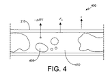
- FIG. 4 is an example of two-phase flow in a flowtube.
- FIG. 5 is a graph of a viscosity correction factor.
- FIG. 6 is a graph comparing predicted values using a bubble model with experimental results.
- FIG. 7 is a graph comparing mass flow error with the drop in density for a series of set liquid flows versus the predicted error.
- FIG. 8 is a map representing gas-liquid flow regimes representing the flow conditions used in testing the model.
- FIG. 9 is a graph comparing a ratio of an actual density to a measured density.
- FIG. 10 is a graph comparing a ratio of an actual mass flow rate to a measured mass flowrate.
- flowtube refers to the flowtube and any associated mechanical parts, drivers, and sensors
- transmitter refers to the electronics for producing drive signals to control the flowtube oscillations and calculating the properties of the material flowing through the flowtube based on signals received from the sensors.
- Coriolis flowmeter may generally refer to a combination of flowtube and transmitter.
- U.S. Pat. No. 6,311,136 which is hereby incorporated by reference, discloses the use of a digital flowmeter system and related technology. Such digital flowmeter systems are very precise in their measurements, with little or negligible noise, and are capable of enabling a wide range of positive and negative gains at the driver circuitry for driving the conduit. Such digital flowmeter systems are thus advantageous in a variety of settings.
- U.S. Pat. No. 6,505,519 discloses the use of a wide gain range, and/or the use of negative gain, to prevent stalling and to more accurately exercise control of the flowtube.
- a digital transmitter exchanges sensor and drive signals with its associated conduit or flowtube, so as to both sense an oscillation of the flowtube, and to drive the oscillation of the flowtube accordingly.
- the digital transmitter may provide for fast and accurate operation of the flowtube in determining characteristics of the flow including a mass flow rate of the flow.
- flowmeter or “meter” is used to refer to any type of device and/or system in which a Coriolis flowmeter system uses various control systems and related elements to measure a mass flow, density, and/or other parameters of a material(s) moving through a flowtube or other conduit.
- FIG. 1A is an illustration of a digital flowmeter using a bent flowtube 102 .
- the bent flowtube 102 may be used to measure one or more physical characteristics of, for example, a (traveling) fluid, as referred to above.
- a digital transmitter 104 exchanges sensor and drive signals with the bent flowtube 102 , so as to both sense an oscillation of the bent flowtube 102 , and to drive the oscillation of the bent flowtube 102 accordingly.
- the digital transmitter 104 provides for fast and accurate operation of the bent flowtube 102 . Examples of the digital transmitter 104 being used with a bent flowtube are provided in, for example, commonly-assigned U.S. Pat. No. 6,311,136.
- FIG. 1B is an illustration of a digital flowmeter using a straight flowtube 106 . More specifically, in FIG. 1B , the straight flowtube 106 interacts with the digital transmitter 104 . Such a straight flowtube operates similarly to the bent flowtube 102 on a conceptual level, and has various advantages/disadvantages relative to the bent flowtube 102 . For example, the straight flowtube 106 may be easier to (completely) fill and empty than the bent flowtube 102 , simply due to the geometry of its construction. In operation, the bent flowtube 102 may operate at a frequency of, for example, 50–110 Hz, while the straight flowtube 106 may operate at a frequency of, for example, 300–1,000 Hz.
- a digital mass flowmeter 200 includes a digital transmitter 104 .
- the digital transmitter 104 may be implemented using one or more of, for example, a processor, a Digital Signal Processor (DSP), a field-programmable gate array (FPGA), an ASIC, other programmable logic or gate arrays, or programmable logic with a processor core.
- the digital flowmeter also may include one or more motion sensors 205 , one or more drivers 210 , and a flowtube 215 (which also may be referred to as a conduit, and which may represent either the bent flowtube 102 , the straight flowtube 106 , or some other type of flowtube).
- Additional sensors may be included and may include a temperature sensor 220 , a pressure sensor 225 , an in-line viscometer 230 , and a gas void fraction sensor 235 .
- the gas void fraction sensor 235 may be used when a fluid flow through the flowtube 215 includes both a liquid and a gas, such as, for example, a liquid containing air bubbles. This condition is also referred to as “two-phase flow.”
- a venturi tube i.e., a tube with a constricted throat that determines fluid pressures and velocities by measurement of differential pressures generated at the throat as a fluid traverses the tube
- a pressure gradient a restriction
- measurements of gas void fractions may be obtained using equipment (e.g., the gas void fraction sensor 235 ) that is wholly external to the flowtube.
- sonar measurements may be taken to determine gas void fraction.
- the SONARtracTM gas void fraction monitoring system produced by CiDRA Corporation of Wallingford, Conn. may be used.
- the digital transmitter 104 generates a measurement of, for example, density and/or mass flow of a material flowing through the flowtube 215 , based at least on signals received from the motion sensors 205 .
- the digital transmitter 104 also controls the drivers 210 to induce motion in the flowtube 215 . This motion is sensed by the motion sensors 205 .
- Density measurements of the material flowing through the flowtube are related to, for example, the frequency of the motion of the flowtube 215 that is induced in the flowtube 215 by a driving force supplied by the drivers 210 , and/or to the temperature of the flowtube 215 .
- mass flow through the flowtube 215 is related to the phase and frequency of the motion of the flowtube 215 , as well as to the temperature of the flowtube 215 .
- the temperature in the flowtube 215 which is measured using the temperature sensor 220 , affects certain properties of the flowtube, such as its stiffness and dimensions.
- the digital transmitter 104 may compensate for these temperature effects.
- a pressure sensor 225 is in communication with the transmitter 104 , and is connected to the flowtube 215 so as to be operable to sense a pressure of a material flowing through the flowtube 215 .
- both the pressure of the fluid entering the flowtube 215 and the pressure drop across relevant points on the flowtube may be indicators of certain flow conditions.
- external temperature sensors may be used to measure the fluid temperature
- such sensors may be used in addition to an internal flowmeter sensor designed to measure a representative temperature for flowtube calibrations.
- some flowtubes use multiple temperature sensors for the purpose of correcting measurements for an effect of differential temperature between the process fluid and the environment (e.g., a case temperature of a housing of the flowtube).
- the digital transmitter 104 can include a variety of measurement and calculation systems.
- the digital transmitter can include an apparent density and mass flow rate determination system 265 .
- the system 265 can generate raw (i.e., uncorrected) values for the density and mass flow rate of the two-phase flow in flowtube 215 for any of several parameters that may affect the true value of these characteristics.
- the temperature can affect the value of density for both the liquid phase and the gas phase.
- two-phase flow itself may result in incorrect apparent readings for density or mass flow.
- the apparent density and mass flowrate can be corrected by the density correction system 240 and the mass flow rate correction system 250 , as discussed in more detail below.
- the density correction database 245 and the mass flow rate correction 255 database should be understood to contain, for example, values generated by the correction systems 240 and 250 , based upon corrections taking into account any of a number of parameters including, for example, temperature, pressure, void fraction, and viscosity.
- FIG. 2 represents one implementation that includes a void fraction determination system 260 , a viscosity determination system 270 , and a liquid phase density determination system 280 .
- Each of these systems may represent, for example, systems that interpret actual sensor data and generate values of the parameter to feed the correction systems 240 and 250 , or, as another example, they may represent systems that generate the parameter data from stored information, or by comparing the stored information to the data gathered or input for other physical parameters.
- the liquid phase density system 280 can produce a value for the density of water at a specific temperature and pressure based on the measured values of temperature and pressure from sensors 220 and 225 , and/or from tabular data for water stored in system 280 .
- a sample of the process liquid can be brought to the actual operating pressure and temperature, and the density can be measured off-line using a densitometer or other device known to those skilled in the art of density determination, and the determined value can be returned to the transmitter 104 either by the system 280 or by physical input of the data.
- the parameter determination systems may include off-line measurement systems or in-line determination systems, and may include systems that connect online devices to the transmitter 104 .
- Such connections can be any of the well-known data transfer connections such as, for example, direct wire connections, wireless connections including optical and RF connections, modem connections, DSL, cable and any other methods of transferring data between two devices.
- FIG. 2 includes the in-line viscometer 230 for determining the liquid viscosity in cooperation with the viscosity determination system 270 .
- the liquid viscosity could be determined by the determination system 270 and an off-line viscometer or rheometer, or could be calculated based on other known physical data, or taken from previously tabulated data.
- Liquid viscosity may be accounted for when monitoring and measuring two-phase gas-liquid flow as discussed herein.
- the digital transmitter 104 may then correct the initially calculated output values for density and mass flow rate, using density and mass flowrate correction systems 240 and 250 .
- systems 240 and 250 may have correction models programmed into them. These correction models can be calculable mathematical models, as discussed in more detail below.
- the correction models also may include historical curve fit models stored in the systems 240 and 250 or can be a combination of a curve fit model and a mathematical model.
- a correction model may be implemented for conditions where curve fitting data is either not available or where the curve fit is no longer an accurate representation of an existing flow regime, while the curve fit is used where it is accurate and available. Additionally, the models may be used simultaneously, producing multiple corrected values for density and flowrate
- a Coriolis flowmeter may, by means of resonant frequency, determine the density of a process fluid in the flowtube 215 . That is, an accurate bulk density of the process fluid can typically be determined.
- the process fluid is a binary mixture of two materials, such as, for example, oil and water.
- two-phase flows a relative percentage of each constituent may be determined using, for example, an algebraic sum or an algorithm relating density to composition.
- Another example of two-phase flow includes a liquid-gas flow, in which the gas forms bubbles flowing within the liquid and through the flowtube.
- the density and mass flow solutions become more complex, and error may be introduced in calculating the mass flow and density as a result of operating difficulties and measurement errors.
- a model may be constructed that assumes such bubble flow and that accounts for, for example, a gas void fraction resulting from the bubble flow and/or a viscosity of the liquid within the two-phase flow.
- FIG. 3 is a flowchart illustrating a process for correcting density and/or mass flow measurement in a two-phase flow.
- the liquid phase viscosity is determined ( 304 ), as well as the liquid phase density ( 306 ) and the gas void fraction ( 308 ), using, for example, the corresponding sensors and systems discussed above with respect to FIG. 2 . Some of these parameters may be dependent on other additional parameters such as temperature or pressure, which can also be measured or calculated using, for example, the systems and sensors of FIG. 2 .
- the viscosity may then be used to determine a viscosity correction factor ( 309 ), referred to as the factor “F” below.
- the correction factor F and some or all of the other determined parameters may be used to determine an error in the apparent values ( 312 ). As a result, a corrected density and mass flow rate may be determined ( 314 ).
- FIG. 4 indicates a short section of Coriolis mass flowmeter tube 400 through which two-phase flow is taking place indicated by bubbles 405 and liquid 410 .
- the tube is undergoing a small amplitude sinusoidal vibration in the z direction (the displacement being the distance z from the static equilibrium position of the tube). It is assumed that the vibrational frequency is so high that during one cycle of vibration the interfaces between the phases do not change geometrically and move along the tube over a small distance compared to the length of the tube section.
- the inertia reaction forces can thus be calculated as if the gas/liquid mixture was suspended in its motion along the tube (i.e. disregarding gravitational forces and surface tension, and flow).
- each liquid element dV experiences an inertia force ⁇ dVz( ⁇ dV ⁇ umlaut over (z) ⁇ ) in the z-direction giving rise to a small vibrational flow of the liquid and a corresponding reaction force F m on the tube:
- FIG. 6 is a graph comparing predicted values using the bubble model just described with experimental results. As can be seen from the graph the bubble model correlates reasonably with the experimental results, and results in a significant drop in the mass flow measurement error. For example, at a flow rate of 1.5 kg/s and a void fraction of 3.3% the measurement error is reduced from about 10% without the viscosity correction to about 3% with the correction. Similarly, for a void fraction of about 6.7%, the mass flow rate measurement error is reduced from about 19% to about 5%.
- FIG. 7 is a graph comparing mass flow error with the drop in density for a series of set liquid flows versus the predicted error from the viscosity corrected model. As can be seen, the mass flow error is small for small gas void fractions of up to about 5%.
- FIG. 8 is a map representing gas-liquid flow regimes used in testing the model.
- test conditions are shown under which experiments described herein were generally conducted. However, it should be understood that the results described herein may be generally applicable to other conditions and/or flow regimes.
- FIG. 9 is a graph comparing a ratio of an actual density to a measured density
- FIG. 10 is a graph comparing a ratio of an actual mass flow rate to a measured mass flowrate.
- superficial liquid and gas velocities are illustrated.
Abstract
Description
-
- Fm =−ρzAm(ρ{umlaut over (z)}Am) or in the complex notation Fm=ρω2zAm per unit length of the tube m, which reduces to
- Am=A the tubes internal cross-sectional area, for single-phase flow.
F c =−i2ρωνδz/δsA c
where ν is the mean flow velocity related to the total volumetric flow rate QL by:
Q L=(1−α)νA
-
- Am=Ac to a good approximation.
F z=−4/3πa 3ρω2 zF
where a is the bubble radius, ρ is the liquid density, ω is the angular frequency of the harmonic motion (=2πf), z is the displacement amplitude in the +νe z-direction and F, i.e., the viscosity correction factor discussed above with respect to
ζ=−a/δ(−1+i)
where
δ=(2ν/ω)0.5
ν being the kinematic viscosity of the liquid. The expression of F in terms of ζ is
where V is the volume of the tube section interior. The inertia reaction force due to several bubbles in the tube section is
where the sum extends over all the bubbles in the tube section. In the summation, a and F depend on bubble size. In terms of void fractions αn for bubbles of radius an, n=1,2,3 . . . N results in
per unit length of tube where A is the internal area of cross-section of the tube. Then an effective area for inertia may be written as
also giving the effective area Ac.
F m=ρω2 zA m=ρω2 z(1−3α)A per unit length of tube
per unit length of tube
ρa=ρ(1−3α)
{dot over (m)} a =ρνA(1−3α) (3).
{dot over (m)}=ρ(1−α)νA
the mass flow fractional error (neglecting the mass of the gas) E{dot over (m)} is
A m =A c=(1−α)A
F m=ρω2 z(1−α)A
ρa=(1−α)ρ
{dot over (m)} a =ρνA(1−α)
giving:
Ed=α
E{dot over (m)}=0.
This suggests that, with the gas density negligible compared with that of the liquid, the density and mass flow registered by the Coriolis meter is the density and mass flow of gas and liquid mixture being homogeneous and with no slip between the phases.
Claims (40)
Priority Applications (3)
| Application Number | Priority Date | Filing Date | Title |
|---|---|---|---|
| US10/873,651 US7072775B2 (en) | 2003-06-26 | 2004-06-23 | Viscosity-corrected flowmeter |
| PCT/US2004/020013 WO2005003690A2 (en) | 2003-06-26 | 2004-06-24 | Viscosity-corrected flowmeter |
| DE112004001119T DE112004001119B4 (en) | 2003-06-26 | 2004-06-24 | Viscosity-corrected flowmeter |
Applications Claiming Priority (2)
| Application Number | Priority Date | Filing Date | Title |
|---|---|---|---|
| US48253703P | 2003-06-26 | 2003-06-26 | |
| US10/873,651 US7072775B2 (en) | 2003-06-26 | 2004-06-23 | Viscosity-corrected flowmeter |
Publications (2)
| Publication Number | Publication Date |
|---|---|
| US20050022611A1 US20050022611A1 (en) | 2005-02-03 |
| US7072775B2 true US7072775B2 (en) | 2006-07-04 |
Family
ID=34107678
Family Applications (1)
| Application Number | Title | Priority Date | Filing Date |
|---|---|---|---|
| US10/873,651 Active US7072775B2 (en) | 2003-06-26 | 2004-06-23 | Viscosity-corrected flowmeter |
Country Status (3)
| Country | Link |
|---|---|
| US (1) | US7072775B2 (en) |
| DE (1) | DE112004001119B4 (en) |
| WO (1) | WO2005003690A2 (en) |
Cited By (5)
| Publication number | Priority date | Publication date | Assignee | Title |
|---|---|---|---|---|
| US20080034890A1 (en) * | 2006-07-21 | 2008-02-14 | Invensys Systems, Inc. | Multi-phase coriolis flowmeter |
| US20100109653A1 (en) * | 2007-01-12 | 2010-05-06 | Koninklijke Philips Electronics N.V. | Sensor device for and a method of sensing particles |
| WO2017062273A1 (en) * | 2015-10-07 | 2017-04-13 | Logilube, LLC | Fluid monitoring and management devices, fluid monitoring and management systems, and fluid monitoring and management methods |
| US10436692B2 (en) * | 2014-12-19 | 2019-10-08 | Endress + Hauser Flowtec Ag | Measuring arrangement and method for measuring the density of flowable media |
| US20220373371A1 (en) * | 2019-10-07 | 2022-11-24 | Endress+Hauser Flowtec Ag | Method for monitoring a measuring device system |
Families Citing this family (25)
| Publication number | Priority date | Publication date | Assignee | Title |
|---|---|---|---|---|
| US7040181B2 (en) * | 2004-03-19 | 2006-05-09 | Endress + Hauser Flowtec Ag | Coriolis mass measuring device |
| US7284449B2 (en) * | 2004-03-19 | 2007-10-23 | Endress + Hauser Flowtec Ag | In-line measuring device |
| DE102005046319A1 (en) | 2005-09-27 | 2007-03-29 | Endress + Hauser Flowtec Ag | Two or multi-phase medium e.g. fluid`s, physical flow parameter e.g. flow rate, measuring method, involves producing measurement values representing parameter by considering pressure difference of medium and by usage of transfer function |
| DE102006031456B4 (en) * | 2006-07-07 | 2019-11-07 | Schaeffler Technologies AG & Co. KG | Storage arrangement with integrated torque measurement and device for controlling a torque distribution |
| PL2115992T3 (en) | 2007-01-29 | 2017-12-29 | Nokia Technologies Oy | Submit report handling in smsip |
| CN101715545B (en) | 2007-05-25 | 2012-04-18 | 微动公司 | Vibratory flow meter and method for correcting for entrained gas in a flow material |
| DE102008050116A1 (en) | 2008-10-06 | 2010-04-08 | Endress + Hauser Flowtec Ag | In-line measuring device |
| DE102008050113A1 (en) | 2008-10-06 | 2010-04-08 | Endress + Hauser Flowtec Ag | In-line measuring device |
| DE102008050115A1 (en) | 2008-10-06 | 2010-04-08 | Endress + Hauser Flowtec Ag | In-line measuring device |
| GB201001948D0 (en) | 2010-02-06 | 2010-03-24 | Mobrey Ltd | Improvements in or relating to vibrating tube densitometers |
| DE102010056418B4 (en) | 2010-12-23 | 2015-12-17 | Volkswagen Ag | Process and device for the treatment of oily sewage |
| US9851239B2 (en) * | 2011-05-23 | 2017-12-26 | Micro Motion, Inc. | System and method for preventing false flow measurements in a vibrating meter |
| DE102011083881A1 (en) * | 2011-09-30 | 2013-04-04 | Krones Aktiengesellschaft | Viscosity-controlled processing of a liquid food |
| GB2529902A (en) * | 2014-09-08 | 2016-03-09 | Simon Parker | Flow meter and aircraft |
| DE102015122225A1 (en) * | 2015-12-18 | 2017-06-22 | Endress + Hauser Flowtec Ag | Method for Reynolds number correction of a flow measurement of a Coriolis flowmeter |
| EP3591349B1 (en) * | 2016-05-16 | 2024-01-03 | Micro Motion Inc. | Multi-channel flow tube |
| DE102016114974A1 (en) | 2016-08-11 | 2018-02-15 | Endress+Hauser Flowtec Ag | Method for determining a gas volume fraction of a gas-laden medium |
| CN107741385B (en) * | 2017-11-10 | 2023-09-12 | 西安航天动力试验技术研究所 | System and method for on-site calibration and measurement of gel viscosity of liquid rocket engine |
| DE102018123534A1 (en) * | 2018-09-25 | 2020-03-26 | Krohne Messtechnik Gmbh | Method for determining the gas content in the medium flowing through a Coriolis mass flow meter |
| DE102019135320A1 (en) * | 2019-12-19 | 2021-06-24 | Endress + Hauser Flowtec Ag | Method for measuring the flow of a medium on the basis of a differential pressure measurement |
| WO2021177961A1 (en) * | 2020-03-05 | 2021-09-10 | Micro Motion, Inc. | Selecting a measurement correction method |
| JP7245806B2 (en) * | 2020-03-27 | 2023-03-24 | マイクロ モーション インコーポレイテッド | How to measure fluids with multi-channel flow tubes |
| DE102020114713A1 (en) | 2020-06-03 | 2021-12-09 | Krohne Ag | Method for determining flow measurement values of a Coriolis mass flow meter in the presence of a two-phase flow |
| CN114459955B (en) * | 2022-03-01 | 2023-09-15 | 天津大学 | Liquid field kinematic viscosity coefficient measurement method based on bubble elasticity characteristics |
| EP4257934A1 (en) | 2022-04-08 | 2023-10-11 | Sensirion AG | Method and device for determining a flow rate |
Citations (49)
| Publication number | Priority date | Publication date | Assignee | Title |
|---|---|---|---|---|
| USRE31450E (en) | 1977-07-25 | 1983-11-29 | Micro Motion, Inc. | Method and structure for flow measurement |
| US4422338A (en) | 1981-02-17 | 1983-12-27 | Micro Motion, Inc. | Method and apparatus for mass flow measurement |
| US4491025A (en) | 1982-11-03 | 1985-01-01 | Micro Motion, Inc. | Parallel path Coriolis mass flow rate meter |
| US4524610A (en) * | 1983-09-02 | 1985-06-25 | National Metal And Refining Company, Ltd. | In-line vibratory viscometer-densitometer |
| US4679947A (en) | 1985-07-16 | 1987-07-14 | Engineering Measurements Co. | Method and apparatus for measuring steam quality |
| US4817448A (en) | 1986-09-03 | 1989-04-04 | Micro Motion, Inc. | Auto zero circuit for flow meter |
| US4852395A (en) | 1988-12-08 | 1989-08-01 | Atlantic Richfield Company | Three phase fluid flow measuring system |
| US4876897A (en) | 1987-12-10 | 1989-10-31 | The Foxboro Company | Steam quality measurement apparatus and method |
| US4879911A (en) | 1988-07-08 | 1989-11-14 | Micro Motion, Incorporated | Coriolis mass flow rate meter having four pulse harmonic rejection |
| US4911006A (en) | 1986-10-03 | 1990-03-27 | Micro Motion Incorporated | Custody transfer meter |
| US4934196A (en) | 1989-06-02 | 1990-06-19 | Micro Motion, Inc. | Coriolis mass flow rate meter having a substantially increased noise immunity |
| US4996871A (en) | 1989-06-02 | 1991-03-05 | Micro Motion, Inc. | Coriolis densimeter having substantially increased noise immunity |
| US5027662A (en) | 1987-07-15 | 1991-07-02 | Micro Motion, Inc. | Accuracy mass flow meter with asymmetry and viscous damping compensation |
| US5029482A (en) | 1989-02-03 | 1991-07-09 | Chevron Research Company | Gas/liquid flow measurement using coriolis-based flow meters |
| US5228327A (en) | 1991-07-11 | 1993-07-20 | Micro Motion, Inc. | Technique for determining a mechanical zero value for a coriolis meter |
| US5259250A (en) | 1990-05-14 | 1993-11-09 | Atlantic Richfield Company | Multi-phase fluid flow mesurement |
| US5295084A (en) * | 1991-10-08 | 1994-03-15 | Micromotion, Inc. | Vibrating tube densimeter |
| US5301557A (en) | 1989-06-09 | 1994-04-12 | Micro Motion, Inc. | Stability coriolis mass flow meter |
| US5347874A (en) | 1993-01-25 | 1994-09-20 | Micro Motion, Incorporated | In-flow coriolis effect mass flowmeter |
| US5359881A (en) | 1992-03-20 | 1994-11-01 | Micro Motion, Incorporated | Viscometer for sanitary applications |
| US5398215A (en) * | 1993-11-19 | 1995-03-14 | Schlumberger Technology Corporation | Identification of stress induced anisotropy in formations |
| US5400653A (en) | 1991-12-23 | 1995-03-28 | Micro Motion, Inc. | Coriolis effect meter using optical fiber sensors |
| US5469748A (en) | 1994-07-20 | 1995-11-28 | Micro Motion, Inc. | Noise reduction filter system for a coriolis flowmeter |
| US5497666A (en) | 1994-07-20 | 1996-03-12 | Micro Motion, Inc. | Increased sensitivity coriolis effect flowmeter using nodal-proximate sensors |
| US5535632A (en) | 1993-10-05 | 1996-07-16 | Atlantic Richfield Company | Systems and methods for measuring flow rates and densities of the components of oil, water and gas mixtures |
| US5555190A (en) | 1995-07-12 | 1996-09-10 | Micro Motion, Inc. | Method and apparatus for adaptive line enhancement in Coriolis mass flow meter measurement |
| US5594180A (en) | 1994-08-12 | 1997-01-14 | Micro Motion, Inc. | Method and apparatus for fault detection and correction in Coriolis effect mass flowmeters |
| US5654502A (en) | 1995-12-28 | 1997-08-05 | Micro Motion, Inc. | Automatic well test system and method of operating the same |
| US5687100A (en) | 1996-07-16 | 1997-11-11 | Micro Motion, Inc. | Vibrating tube densimeter |
| US5734112A (en) | 1996-08-14 | 1998-03-31 | Micro Motion, Inc. | Method and apparatus for measuring pressure in a coriolis mass flowmeter |
| US5821407A (en) * | 1993-09-29 | 1998-10-13 | Toki Sangyo Co., Ltd. | Automatic viscosity measuring apparatus with rotor automatically detachable |
| US5969264A (en) | 1998-11-06 | 1999-10-19 | Technology Commercialization Corp. | Method and apparatus for total and individual flow measurement of a single-or multi-phase medium |
| US6006609A (en) * | 1996-12-11 | 1999-12-28 | Endress + Hauser Flowtec Ag | Coriolis mass flow/density sensor with a single straight measuring tube |
| US6032539A (en) | 1996-10-11 | 2000-03-07 | Accuflow, Inc. | Multiphase flow measurement method and apparatus |
| US6092429A (en) | 1997-12-04 | 2000-07-25 | Micro Motion, Inc. | Driver for oscillating a vibrating conduit |
| US6176323B1 (en) * | 1997-06-27 | 2001-01-23 | Baker Hughes Incorporated | Drilling systems with sensors for determining properties of drilling fluid downhole |
| US6233526B1 (en) * | 1998-07-16 | 2001-05-15 | Micro Motion, Inc. | Vibrating conduit parameter sensors and methods of operation therefor utilizing spatial integration |
| US6311136B1 (en) * | 1997-11-26 | 2001-10-30 | Invensys Systems, Inc. | Digital flowmeter |
| US6318156B1 (en) | 1999-10-28 | 2001-11-20 | Micro Motion, Inc. | Multiphase flow measurement system |
| US6318186B1 (en) | 1999-06-28 | 2001-11-20 | Micro Motion, Inc. | Type identification and parameter selection for drive control in a coriolis flowmeter |
| US6327914B1 (en) | 1998-09-30 | 2001-12-11 | Micro Motion, Inc. | Correction of coriolis flowmeter measurements due to multiphase flows |
| WO2002008703A1 (en) | 2000-07-21 | 2002-01-31 | Micro Motion, Inc. | A system for calibrating a drive signal in a coriolis flowmeter |
| US6343507B1 (en) * | 1998-07-30 | 2002-02-05 | Schlumberger Technology Corporation | Method to improve the quality of a formation fluid sample |
| US6360579B1 (en) * | 1999-03-26 | 2002-03-26 | Micro Motion, Inc. | Flowmeter calibration system with statistical optimization technique |
| US6505131B1 (en) | 1999-06-28 | 2003-01-07 | Micro Motion, Inc. | Multi-rate digital signal processor for signals from pick-offs on a vibrating conduit |
| US6505519B2 (en) * | 2000-03-23 | 2003-01-14 | Invensys Systems, Inc. | Correcting for two-phase flow in a digital flowmeter |
| US6609067B2 (en) * | 2000-06-06 | 2003-08-19 | Halliburton Energy Services, Inc. | Real-time method for maintaining formation stability and monitoring fluid-formation interaction |
| US6651513B2 (en) * | 2000-04-27 | 2003-11-25 | Endress + Hauser Flowtec Ag | Vibration meter and method of measuring a viscosity of a fluid |
| US6763730B1 (en) * | 1999-05-25 | 2004-07-20 | Abb Limited | Vibrating tube meter |
Family Cites Families (5)
| Publication number | Priority date | Publication date | Assignee | Title |
|---|---|---|---|---|
| US4718443A (en) * | 1987-02-06 | 1988-01-12 | Conoco Inc. | Mass flowmeter apparatus |
| US4987914A (en) * | 1989-01-11 | 1991-01-29 | Conoco Inc. | Mass flowmeter apparatus |
| US5741980A (en) * | 1994-11-02 | 1998-04-21 | Foster-Miller, Inc. | Flow analysis system and method |
| US6170338B1 (en) * | 1997-03-27 | 2001-01-09 | Rosemont Inc. | Vortex flowmeter with signal processing |
| CN1178048C (en) * | 1998-12-11 | 2004-12-01 | 安德雷斯和霍瑟·弗罗泰克有限公司 | Coriolis-type mass flowmeter/densimeter |
-
2004
- 2004-06-23 US US10/873,651 patent/US7072775B2/en active Active
- 2004-06-24 DE DE112004001119T patent/DE112004001119B4/en not_active Revoked
- 2004-06-24 WO PCT/US2004/020013 patent/WO2005003690A2/en active Application Filing
Patent Citations (56)
| Publication number | Priority date | Publication date | Assignee | Title |
|---|---|---|---|---|
| USRE31450E (en) | 1977-07-25 | 1983-11-29 | Micro Motion, Inc. | Method and structure for flow measurement |
| US4422338A (en) | 1981-02-17 | 1983-12-27 | Micro Motion, Inc. | Method and apparatus for mass flow measurement |
| US4422338B1 (en) | 1981-02-17 | 1987-07-14 | ||
| US4491025A (en) | 1982-11-03 | 1985-01-01 | Micro Motion, Inc. | Parallel path Coriolis mass flow rate meter |
| US4491025B1 (en) | 1982-11-03 | 1988-01-05 | ||
| US4524610A (en) * | 1983-09-02 | 1985-06-25 | National Metal And Refining Company, Ltd. | In-line vibratory viscometer-densitometer |
| US4679947A (en) | 1985-07-16 | 1987-07-14 | Engineering Measurements Co. | Method and apparatus for measuring steam quality |
| US4817448A (en) | 1986-09-03 | 1989-04-04 | Micro Motion, Inc. | Auto zero circuit for flow meter |
| US4911006A (en) | 1986-10-03 | 1990-03-27 | Micro Motion Incorporated | Custody transfer meter |
| US5027662A (en) | 1987-07-15 | 1991-07-02 | Micro Motion, Inc. | Accuracy mass flow meter with asymmetry and viscous damping compensation |
| US4876897A (en) | 1987-12-10 | 1989-10-31 | The Foxboro Company | Steam quality measurement apparatus and method |
| US4879911A (en) | 1988-07-08 | 1989-11-14 | Micro Motion, Incorporated | Coriolis mass flow rate meter having four pulse harmonic rejection |
| US4852395A (en) | 1988-12-08 | 1989-08-01 | Atlantic Richfield Company | Three phase fluid flow measuring system |
| US5029482A (en) | 1989-02-03 | 1991-07-09 | Chevron Research Company | Gas/liquid flow measurement using coriolis-based flow meters |
| US4934196A (en) | 1989-06-02 | 1990-06-19 | Micro Motion, Inc. | Coriolis mass flow rate meter having a substantially increased noise immunity |
| US4996871A (en) | 1989-06-02 | 1991-03-05 | Micro Motion, Inc. | Coriolis densimeter having substantially increased noise immunity |
| US5301557A (en) | 1989-06-09 | 1994-04-12 | Micro Motion, Inc. | Stability coriolis mass flow meter |
| US5259250A (en) | 1990-05-14 | 1993-11-09 | Atlantic Richfield Company | Multi-phase fluid flow mesurement |
| US5228327A (en) | 1991-07-11 | 1993-07-20 | Micro Motion, Inc. | Technique for determining a mechanical zero value for a coriolis meter |
| US5295084A (en) * | 1991-10-08 | 1994-03-15 | Micromotion, Inc. | Vibrating tube densimeter |
| US5400653A (en) | 1991-12-23 | 1995-03-28 | Micro Motion, Inc. | Coriolis effect meter using optical fiber sensors |
| US5359881A (en) | 1992-03-20 | 1994-11-01 | Micro Motion, Incorporated | Viscometer for sanitary applications |
| US5347874A (en) | 1993-01-25 | 1994-09-20 | Micro Motion, Incorporated | In-flow coriolis effect mass flowmeter |
| US5821407A (en) * | 1993-09-29 | 1998-10-13 | Toki Sangyo Co., Ltd. | Automatic viscosity measuring apparatus with rotor automatically detachable |
| US5535632A (en) | 1993-10-05 | 1996-07-16 | Atlantic Richfield Company | Systems and methods for measuring flow rates and densities of the components of oil, water and gas mixtures |
| US5398215A (en) * | 1993-11-19 | 1995-03-14 | Schlumberger Technology Corporation | Identification of stress induced anisotropy in formations |
| US5469748A (en) | 1994-07-20 | 1995-11-28 | Micro Motion, Inc. | Noise reduction filter system for a coriolis flowmeter |
| US5497666A (en) | 1994-07-20 | 1996-03-12 | Micro Motion, Inc. | Increased sensitivity coriolis effect flowmeter using nodal-proximate sensors |
| US5594180A (en) | 1994-08-12 | 1997-01-14 | Micro Motion, Inc. | Method and apparatus for fault detection and correction in Coriolis effect mass flowmeters |
| US5555190A (en) | 1995-07-12 | 1996-09-10 | Micro Motion, Inc. | Method and apparatus for adaptive line enhancement in Coriolis mass flow meter measurement |
| US5654502A (en) | 1995-12-28 | 1997-08-05 | Micro Motion, Inc. | Automatic well test system and method of operating the same |
| US5687100A (en) | 1996-07-16 | 1997-11-11 | Micro Motion, Inc. | Vibrating tube densimeter |
| US5734112A (en) | 1996-08-14 | 1998-03-31 | Micro Motion, Inc. | Method and apparatus for measuring pressure in a coriolis mass flowmeter |
| US6032539A (en) | 1996-10-11 | 2000-03-07 | Accuflow, Inc. | Multiphase flow measurement method and apparatus |
| US6006609A (en) * | 1996-12-11 | 1999-12-28 | Endress + Hauser Flowtec Ag | Coriolis mass flow/density sensor with a single straight measuring tube |
| US6176323B1 (en) * | 1997-06-27 | 2001-01-23 | Baker Hughes Incorporated | Drilling systems with sensors for determining properties of drilling fluid downhole |
| US6754594B2 (en) * | 1997-11-26 | 2004-06-22 | Invensys Systems, Inc. | Digital flowmeter |
| US6311136B1 (en) * | 1997-11-26 | 2001-10-30 | Invensys Systems, Inc. | Digital flowmeter |
| US6507791B2 (en) * | 1997-11-26 | 2003-01-14 | Invensys Systems, Inc. | Digital flowmeter |
| US6092429A (en) | 1997-12-04 | 2000-07-25 | Micro Motion, Inc. | Driver for oscillating a vibrating conduit |
| US6233526B1 (en) * | 1998-07-16 | 2001-05-15 | Micro Motion, Inc. | Vibrating conduit parameter sensors and methods of operation therefor utilizing spatial integration |
| US6343507B1 (en) * | 1998-07-30 | 2002-02-05 | Schlumberger Technology Corporation | Method to improve the quality of a formation fluid sample |
| US6327914B1 (en) | 1998-09-30 | 2001-12-11 | Micro Motion, Inc. | Correction of coriolis flowmeter measurements due to multiphase flows |
| US5969264A (en) | 1998-11-06 | 1999-10-19 | Technology Commercialization Corp. | Method and apparatus for total and individual flow measurement of a single-or multi-phase medium |
| US6360579B1 (en) * | 1999-03-26 | 2002-03-26 | Micro Motion, Inc. | Flowmeter calibration system with statistical optimization technique |
| US6763730B1 (en) * | 1999-05-25 | 2004-07-20 | Abb Limited | Vibrating tube meter |
| US6318186B1 (en) | 1999-06-28 | 2001-11-20 | Micro Motion, Inc. | Type identification and parameter selection for drive control in a coriolis flowmeter |
| US6505131B1 (en) | 1999-06-28 | 2003-01-07 | Micro Motion, Inc. | Multi-rate digital signal processor for signals from pick-offs on a vibrating conduit |
| US6318156B1 (en) | 1999-10-28 | 2001-11-20 | Micro Motion, Inc. | Multiphase flow measurement system |
| US6564619B2 (en) | 1999-10-28 | 2003-05-20 | Micro Motion, Inc. | Multiphase flow measurement system |
| US20020033043A1 (en) | 1999-10-28 | 2002-03-21 | Dutton Robert E. | Multiphase flow measurement system |
| US6505519B2 (en) * | 2000-03-23 | 2003-01-14 | Invensys Systems, Inc. | Correcting for two-phase flow in a digital flowmeter |
| US6758102B2 (en) * | 2000-03-23 | 2004-07-06 | Invensys Systems, Inc. | Correcting for two-phase flow in a digital flowmeter |
| US6651513B2 (en) * | 2000-04-27 | 2003-11-25 | Endress + Hauser Flowtec Ag | Vibration meter and method of measuring a viscosity of a fluid |
| US6609067B2 (en) * | 2000-06-06 | 2003-08-19 | Halliburton Energy Services, Inc. | Real-time method for maintaining formation stability and monitoring fluid-formation interaction |
| WO2002008703A1 (en) | 2000-07-21 | 2002-01-31 | Micro Motion, Inc. | A system for calibrating a drive signal in a coriolis flowmeter |
Non-Patent Citations (5)
| Title |
|---|
| Hemp J., Sultan, G. (1989) "On the theory and performance of Coriolis mass flowmeter" Proc of the International Conference on Mass Flow Measurement Direct and Indirect, 1989, Feb. IBC Technical Services, London, 1989. |
| Lamb, H. (1975) "Hydrodynamics" 6<SUP>th </SUP>Ed (1975) CUP, p. 505. |
| Lui, R.P., Fuent, M.J., Henry, M.P., Duta, M.D.(2001) "A neural network to correct mass flow errors caused by two phase flow in a digital Coriolis mass flowmeter" Journal of Flow Measurement and Instrumentation, 12 (2001), pp. 53-63. |
| Reizner, "Coriolis-The Almost Perfect Flow Meter," Colloquium on Coriolis Mass Flow Metering, Oxford, Jun. 2003. |
| Wenger, A; "Vibrating Fluid Densimeters: A Solution To The Viscosity Problem"; IEEE Transactions on Industrial Electroincs an Control Instrumentation; vol. 1 IECI-27 No. 3; pp. 247-253. * |
Cited By (9)
| Publication number | Priority date | Publication date | Assignee | Title |
|---|---|---|---|---|
| US20080034890A1 (en) * | 2006-07-21 | 2008-02-14 | Invensys Systems, Inc. | Multi-phase coriolis flowmeter |
| US7614312B2 (en) * | 2006-07-21 | 2009-11-10 | Invensys Systems, Inc. | Multi-phase coriolis flowmeter |
| US20100094568A1 (en) * | 2006-07-21 | 2010-04-15 | Invensys Systems, Inc. | Multi-phase coriolis flowmeter |
| US20100109653A1 (en) * | 2007-01-12 | 2010-05-06 | Koninklijke Philips Electronics N.V. | Sensor device for and a method of sensing particles |
| US8970215B2 (en) * | 2007-01-12 | 2015-03-03 | Koninklijkle Philips N.V. | Sensor device for and a method of sensing particles |
| US10436692B2 (en) * | 2014-12-19 | 2019-10-08 | Endress + Hauser Flowtec Ag | Measuring arrangement and method for measuring the density of flowable media |
| WO2017062273A1 (en) * | 2015-10-07 | 2017-04-13 | Logilube, LLC | Fluid monitoring and management devices, fluid monitoring and management systems, and fluid monitoring and management methods |
| US10466152B2 (en) | 2015-10-07 | 2019-11-05 | Logilube, LLC | Fluid monitoring and management devices, fluid monitoring and management systems, and fluid monitoring and management methods |
| US20220373371A1 (en) * | 2019-10-07 | 2022-11-24 | Endress+Hauser Flowtec Ag | Method for monitoring a measuring device system |
Also Published As
| Publication number | Publication date |
|---|---|
| WO2005003690A2 (en) | 2005-01-13 |
| US20050022611A1 (en) | 2005-02-03 |
| DE112004001119B4 (en) | 2009-01-02 |
| DE112004001119T5 (en) | 2006-06-01 |
| WO2005003690A3 (en) | 2005-04-28 |
Similar Documents
| Publication | Publication Date | Title |
|---|---|---|
| US7072775B2 (en) | Viscosity-corrected flowmeter | |
| US7726203B2 (en) | Multiphase Coriolis flowmeter | |
| US7930114B2 (en) | Compensating for frequency change in flowmeters | |
| US10718648B2 (en) | Method for determining a physical parameter of a compressible medium with a measuring transducer of vibration-type and measuring transducer for performing such a method | |
| US7185526B2 (en) | Flowmeter calibration techniques | |
| US7188534B2 (en) | Multi-phase coriolis flowmeter | |
| US9091581B2 (en) | Wet gas measurement | |
| US7257988B2 (en) | Densitometer with pulsing pressure | |
| US8738305B2 (en) | Method for detecting blockage in a Coriolis flow measuring device | |
| EP1817554B1 (en) | Method and apparatus for determining flow pressure using density information | |
| US8892371B2 (en) | Wet gas measurement | |
| EP1724558A1 (en) | Coriolis mass flow/density measuring devices and method for compensating measurement errors in such devices | |
| MX2013014108A (en) | Vibratory flow meter and zero check method. | |
| EP2926096B1 (en) | Vibrating type flow meter, meter electronics and flow metering method with detection of fluid tube cross-sectional area changes by determining tube stiffness by the help of a lateral vibration mode | |
| EP3775792B1 (en) | Flowmeter phase fraction and concentration measurement adjustment method and apparatus | |
| RU2420715C2 (en) | Multi-phase coriolis flowmetre |
Legal Events
| Date | Code | Title | Description |
|---|---|---|---|
| AS | Assignment |
Owner name: INVENSYS SYSTEMS, INC., MASSACHUSETTS Free format text: ASSIGNMENT OF ASSIGNORS INTEREST;ASSIGNORS:HEMP, JOHN;YEUNG, HOI CHEONG;REEL/FRAME:015239/0263 Effective date: 20041008 |
|
| STCF | Information on status: patent grant |
Free format text: PATENTED CASE |
|
| AS | Assignment |
Owner name: DEUTSCHE BANK AG, LONDON BRANCH,UNITED KINGDOM Free format text: SECURITY AGREEMENT;ASSIGNOR:INVENSYS SYSTEMS, INC.;REEL/FRAME:017921/0766 Effective date: 20060713 Owner name: DEUTSCHE BANK AG, LONDON BRANCH, UNITED KINGDOM Free format text: SECURITY AGREEMENT;ASSIGNOR:INVENSYS SYSTEMS, INC.;REEL/FRAME:017921/0766 Effective date: 20060713 |
|
| FPAY | Fee payment |
Year of fee payment: 4 |
|
| AS | Assignment |
Owner name: INVENSYS SYSTEMS, INC., MASSACHUSETTS Free format text: RELEASE BY SECURED PARTY;ASSIGNOR:DEUTSCHE BANK AG, LONDON BRANCH;REEL/FRAME:030982/0737 Effective date: 20080723 |
|
| FPAY | Fee payment |
Year of fee payment: 8 |
|
| AS | Assignment |
Owner name: SCHNEIDER ELECTRIC SYSTEMS USA, INC., MASSACHUSETT Free format text: CHANGE OF NAME;ASSIGNOR:INVENSYS SYSTEMS, INC.;REEL/FRAME:043379/0925 Effective date: 20170101 |
|
| MAFP | Maintenance fee payment |
Free format text: PAYMENT OF MAINTENANCE FEE, 12TH YEAR, LARGE ENTITY (ORIGINAL EVENT CODE: M1553) Year of fee payment: 12 |