US7041094B2 - Tissue treatment device and method - Google Patents
Tissue treatment device and method Download PDFInfo
- Publication number
- US7041094B2 US7041094B2 US10/687,040 US68704003A US7041094B2 US 7041094 B2 US7041094 B2 US 7041094B2 US 68704003 A US68704003 A US 68704003A US 7041094 B2 US7041094 B2 US 7041094B2
- Authority
- US
- United States
- Prior art keywords
- skin
- patient
- window
- area
- laser
- Prior art date
- Legal status (The legal status is an assumption and is not a legal conclusion. Google has not performed a legal analysis and makes no representation as to the accuracy of the status listed.)
- Expired - Fee Related
Links
Images


Classifications
-
- A—HUMAN NECESSITIES
- A61—MEDICAL OR VETERINARY SCIENCE; HYGIENE
- A61B—DIAGNOSIS; SURGERY; IDENTIFICATION
- A61B18/00—Surgical instruments, devices or methods for transferring non-mechanical forms of energy to or from the body
- A61B18/18—Surgical instruments, devices or methods for transferring non-mechanical forms of energy to or from the body by applying electromagnetic radiation, e.g. microwaves
- A61B18/20—Surgical instruments, devices or methods for transferring non-mechanical forms of energy to or from the body by applying electromagnetic radiation, e.g. microwaves using laser
- A61B18/203—Surgical instruments, devices or methods for transferring non-mechanical forms of energy to or from the body by applying electromagnetic radiation, e.g. microwaves using laser applying laser energy to the outside of the body
-
- A—HUMAN NECESSITIES
- A61—MEDICAL OR VETERINARY SCIENCE; HYGIENE
- A61B—DIAGNOSIS; SURGERY; IDENTIFICATION
- A61B18/00—Surgical instruments, devices or methods for transferring non-mechanical forms of energy to or from the body
- A61B2018/00005—Cooling or heating of the probe or tissue immediately surrounding the probe
- A61B2018/00011—Cooling or heating of the probe or tissue immediately surrounding the probe with fluids
- A61B2018/00023—Cooling or heating of the probe or tissue immediately surrounding the probe with fluids closed, i.e. without wound contact by the fluid
-
- A—HUMAN NECESSITIES
- A61—MEDICAL OR VETERINARY SCIENCE; HYGIENE
- A61B—DIAGNOSIS; SURGERY; IDENTIFICATION
- A61B18/00—Surgical instruments, devices or methods for transferring non-mechanical forms of energy to or from the body
- A61B2018/00005—Cooling or heating of the probe or tissue immediately surrounding the probe
- A61B2018/00011—Cooling or heating of the probe or tissue immediately surrounding the probe with fluids
- A61B2018/00029—Cooling or heating of the probe or tissue immediately surrounding the probe with fluids open
-
- A—HUMAN NECESSITIES
- A61—MEDICAL OR VETERINARY SCIENCE; HYGIENE
- A61B—DIAGNOSIS; SURGERY; IDENTIFICATION
- A61B18/00—Surgical instruments, devices or methods for transferring non-mechanical forms of energy to or from the body
- A61B2018/00005—Cooling or heating of the probe or tissue immediately surrounding the probe
- A61B2018/00041—Heating, e.g. defrosting
-
- A—HUMAN NECESSITIES
- A61—MEDICAL OR VETERINARY SCIENCE; HYGIENE
- A61B—DIAGNOSIS; SURGERY; IDENTIFICATION
- A61B18/00—Surgical instruments, devices or methods for transferring non-mechanical forms of energy to or from the body
- A61B2018/00315—Surgical instruments, devices or methods for transferring non-mechanical forms of energy to or from the body for treatment of particular body parts
- A61B2018/00452—Skin
- A61B2018/00458—Deeper parts of the skin, e.g. treatment of vascular disorders or port wine stains
-
- A—HUMAN NECESSITIES
- A61—MEDICAL OR VETERINARY SCIENCE; HYGIENE
- A61B—DIAGNOSIS; SURGERY; IDENTIFICATION
- A61B18/00—Surgical instruments, devices or methods for transferring non-mechanical forms of energy to or from the body
- A61B2018/00315—Surgical instruments, devices or methods for transferring non-mechanical forms of energy to or from the body for treatment of particular body parts
- A61B2018/00452—Skin
- A61B2018/00476—Hair follicles
Definitions
- wavelength-selective photo-thermolysis Use of light to denature very specific kinds of tissue has been called wavelength-selective photo-thermolysis.
- the use of lasers for this purpose has been well described in the literature. See, for example, R. G. Wheland, “Laser-assisted hair removal”, Lasers in Dermatology , Vol. 15, pp. 469–477, and references cited.
- a laser with the right wavelength and energy per unit area (fluence) a particular light-absorbing target substance (chromophore) in living tissue, such as melanin or hemoglobin, will absorb energy from the laser beam and become hot enough to destroy functionality in the tissue containing the chromophore. Tissue in the same area that does not have high concentration of the target chromophore will not be affected.
- Hair includes two basic parts, the shaft, which is the portion of the hair above the epidermis, and the root, which is the portion below the surface of the epidermis.
- Various tissues surround the root of the hair. Hair color is primarily do to the presence of melanin in the hair. Melanin is created at the base of the hair follicle and is passed into the hair as it grows. The presence of melanin has made it possible to use lasers and other light sources for hair removal with melanin as the target chromophore.
- the hair follicle and surrounding structure (referred to collectively as hair tissue) are selectively heated when the melanin in the hair tissue and in the hair root itself and is exposed to treatment radiation. The hair tissue is thermally damaged so that a result of the localized heating, many of the exposed hairs later atrophy and are sloughed from the epidermis.
- the pulsed ruby laser (694 nm).
- Long pulse ruby lasers (as opposed to Q-switched ruby lasers) typically have a pulse duration in the 1 millisecond range.
- the wavelength is highly absorbed in melanin, the wavelength selection has significant limitations with darker skin types as the epidermis can blister from the superficial melanin heating.
- Lightsheer One commercially-available system, sold by Coherent of Santa Clara as Lightsheer, weighs in the 45 kg (100 pound) range and allows the physician to treat the darkest skin types with minimal risk of post operative blistering.
- the high pulse energy diode approach is very expensive as it requires up to 100 diode bars to achieve the peak powers needed for the desired clinical result.
- Another limitation with this approach is in the delivery device.
- the current Lightsheer system houses all diodes and associated hardware in a handpiece that is used in direct contact with the skin. This approach results in a heavy handpiece, weighing several pounds, that causes user fatigue and an overall bulky design.
- Dermatologists have used cooling devices in dermatologic applications prior to laser treatment. The purpose is to chill the skin with the understanding that exposure to treatment radiation will elevate the epidermal temperature. Chilling lowers the initial temperature so that the post treatment temperature at the epidermis will not create a heat-induced blister.
- U.S. Pat. No. 5,735,844 describes apparatus which uses a cooled lens, through which radiation passes, pressed against the patient's skin to cool the epidermis.
- the present invention is directed to a hair removal device and method by which hair tissue-damaging radiation passes from a radiation source through a recessed window to the patient's skin.
- the hair removal device also includes a skin-cooling element having a cooling surface which is used to contact the skin prior to exposure of that skin area to the radiation.
- the window is laterally offset from the cooling surface as well as spaced apart from the cooling surface in a direction away from the patient's skin so to create a gap between the window and the patient's skin.
- the presence of a gap between the window of the radiation source and the patient's skin offers several benefits.
- One problem associated with a contact cooling window in direct contact with the skin is debris build up. Dermatologic tissue accumulates on the contact window as treatment pulses are delivered. The window must be periodically wiped in order to preserve the window from local, intense overheating that thermally and mechanically stresses the window and causes pitting. A recessed window does not exhibit this problem.
- Another advantage is that the window can be kept warm and above the local dewpoint temperature for both the inner and outer surfaces, so water and other condensables do not collect on it. Since the window is not in contact with the skin, it does not cause any re-heating of the pre-cooled skin.
- the radiation source includes an optical chamber having an exit aperture covered by the recessed window and an optical fiber entrance in which an optical fiber can be housed to permit tissue-damaging radiation to pass from the optical fiber into the optical chamber.
- the optical chamber may also be heated to help prevent condensation from forming on the walls of the chamber or the window.
- the window may include both an inner window and an outer, user-replaceable window; if the outer window becomes damaged through use, it can be easily replaced without affecting the integrity of the optical chamber. This is an advantage over fixed, single window designs that are rendered unusable if there is a surface imperfection due to, for example, localized pitting.
- the hair removal device may be coupled to a laser which supplies laser light to the radiation source for passage through the recessed window.
- the laser may be controlled by user-operated laser power inputs including a laser-pulse duration input and one of a laser-pulse amplitude input and a laser-pulse fluence input.
- the laser-pulse duration input may be adjusted according to the diameter of the hair, which corresponds to the thermal relaxation time of the hair. Therefore, smaller diameter hairs will typically call for shorter laser-pulse duration inputs while larger diameter hairs will call for a longer laser-pulse duration inputs.
- Another aspect of the invention relates to a method for removing hair including the steps of (1) determining the diameter typical of the hair to be removed, (2) selecting a laser-pulse duration for a hair removal device according to this diameter of the hair so that smaller diameter hair results in a shorter laser-pulse duration than larger diameter hair, and (3) applying laser energy through a window of a hair removal device of the selected laser-pulse duration to a patient's skin to cause thermal injury to hair tissue. This applies to both individual hairs and a plurality of hairs.
- the method may include selecting a chosen one of a laser-pulse amplitude and a laser-pulse fluence prior to the applying step. Further, the method may also include positioning a cooling element of the hair removal device against a first target area and then moving, after a period of time, the cooling element from the first target area to a second target area so that the window overlies and is spaced apart from the first target area; laser energy is then applied to the first target area through the window with the window overlying and spaced apart from the first target area.
- a short pulse typically in the sub-5 ms, range creates high peak powers because high fluence is required to deliver enough energy to achieve the proper clinical endpoint. High peak power tends to heat the epidermis. Longer pulses result in lower peak power.
- Shorter wavelengths such as 694 nm
- Shorter wavelengths do not penetrate deeply into the patient's skin so, some believe, that it may be desirable, with such shorter wavelengths, to use a convex window pressing against the skin to shorten the path from the window to the hair tissue as is taught by U.S. Pat. No. 5,735,844 patent. It has been found that by the use of longer wavelengths which are still absorbed by melanin, such as 800 to 1200 nm, it is not necessary for the window of the radiation source to press against the patient's skin to effectively irradiate the hair tissue at a target area.
- Another aspect of the invention is the recognition that it is not necessary to cool the skin the same time it is being irradiated. This is because once the skin has been cooled through contact with a cold surface, removal of the cold surface permits the skin to warm up but it does so much more slowly than it has cooled down because it is relying almost entirely on convection rather than conduction. Recognizing the fact that the skin remains sufficiently cool for a second or two after removal of the cooling surface permits the window of the radiation source to be positioned spaced apart from the surface of the skin. This eliminates some problems created when the window of the radiation source directly contacts the skin during irradiation, such as window surface damage caused by intense heating from hair fragments that are heated by the laser beam.
- a further aspect of the invention is the recognition that radiation in the longer wavelengths (about 800 to 1200 nm) of the band of melanin-absorbing radiation, typically considered from about 600 nm to 1200 nm, can be used without the need for the use of chromophore contaminants as taught by U.S. Pat. No. 5,425,728.
- FIG. 1 is a simplified cross-sectional view of a hair with its root within a hair follicle
- FIG. 2 plots absorption coefficient versus wavelength for different substances including melanin
- FIG. 3 is a schematic representation of a hair removal assembly made according to the invention.
- FIG. 3A is a simplified side view of the hair removal device of FIG. 3 with portions broken away to show internal detail;
- FIG. 3B is a simplified cross-sectional view taken along line 3 B- 3 B of FIG. 3A ;
- FIG. 4 is a bottom plan view of the hair removal device of FIG. 3A ;
- FIG. 4A is an overall view of the lower end of an alternative embodiment of the hair removal device of FIG. 3A ;
- FIG. 5 is a theoretical plot of fluence versus radial position for a diverging beam
- FIG. 5A shows an idealized plot of how to square off or equalize the fluence of the beam of FIG. 5 ;
- FIG. 6 is a simplified view of the radiation source of FIG. 3 showing how radiation is reflected from the walls of the reflective chamber to help equalize radiation intensity and reduce hot spots;
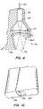
- FIG. 7 shows several idealized plots of temperature versus depth below the skin surface
- FIGS. 8A , 8 b , 8 C and 8 D are two isometric views, a top plan view and an end view of another alternative embodiment of the hair removal device of FIG. 3A with the ergonomically shaped body removed;
- FIG. 9 is a simplified partial cross-sectional view of an alternative embodiment of the hair removal device of FIG. 3A in which the device is configured to permit the user to see the skin area being treated;
- FIG. 10 is a simplified view of the bottom of a further alternative embodiment of the hair removal device of FIG. 3A showing leading and trailing cooling surfaces.
- FIG. 1 illustrates, in simplified form, a hair 2 including a shaft 4 extending above skin surface 6 and a root 8 extending below the skin surface.
- the root 8 passes through epidermis 10 into dermis 12 with the base of the root being about 4 mm below surface 6 .
- Root 8 is housed within hair follicle 14 , hair follicle 14 being surrounded by various tissues including connective tissue sheath 16 and blood vessels 18 .
- the various tissues closely surrounding root 8 and connected with the growth of hair 2 including hair follicle 14 and connective tissue sheath 16 , are collectively referred to as hair tissue 20 in this application.
- wavelengths in the 800 to 1200 nm range in particular, an Nd:YAG (neodimium-doped YAG) laser having a wavelength of 1.06 micron is preferred because it is a relatively efficient source and the technology is well developed and readily available.
- FIG. 3 illustrates, schematically, a hair removal assembly 21 including a hand-held hair removal device 22 , device 22 shown in more detail in the simplified views of FIGS. 3A and 3B .
- Device 22 includes a hand-grippable body 24 having an upper or outer end 26 into which an umbilical cable 28 passes.
- Body 24 also has a lower or skin contacting end 30 housing a formed aluminum block 32 , block 32 having various cavities to provide various features and functions as described below.
- Block 32 defines a cooling surface 34 , see also FIG. 4 , which is used to contact the patient's skin and cool the skin and prior to irradiation.
- Surface 34 is a low friction, high lubricity surface to help prevent bonding between the cooling surface and the skin.
- Aluminum block 32 also houses a radiation source 36 .
- Radiation source 36 includes a reflective chamber 38 , in this embodiment having a square cross-sectional shape.
- Reflective chamber 38 has its walls covered with a highly reflective material, such as gold; the material is chosen for its reflective qualities for the particular wavelength radiation to be used. Other materials, such as dielectric layers combined with high-reflectivity metals, could also be used.
- Chamber 38 has an optical fiber entrance 40 to permit an optical fiber 42 , or a bundle of optical fibers, to extend into chamber 38 .
- the opposite end of chamber 38 has an exit aperture 44 covered by a recessed window 46 .
- Recessed window 46 is spaced apart from cooling surface 34 by a distance or gap 47 , such as about 1 to 3 mm (0.04 to 0.12 in).
- Recessed window 46 includes an inner window 48 , typically permanently or semi-permanently mounted to aluminum block 32 at exit aperture 44 , and an outer window 50 .
- Outer window 50 is removable secured in place by the use of an clip, not shown, or other suitable means.
- Windows 48 , 50 are made of a suitable material, such as fused silica, although other materials, such as optical glasses, could also be used.
- inner and outer windows 48 , 50 if outer window 50 is damaged, it can be easily replaced by the user. Accordingly, outer window 50 acts as a sacrificial window which if damaged, such as can occur through spalling as a result of bits of hair exploding when subjected to high power radiation, can be easily replaced.
- Cooling surface 34 is cooled through the use of a coolant evaporator 52 house within a blind bore 54 formed in aluminum block 30 .
- the coolant which may be of various commercially available types, commonly Freon® or other fluorinated hydrocarbons, is directed to evaporator 52 through a coolant liquid line 56 and is recycled back to a refrigerant compressor 62 through a coolant vapor return line 58 .
- Line 58 coaxially houses coolant liquid line 56 , line 58 being housed within thermal insulation 60 .
- Lines 56 , 58 and insulation 60 pass through umbilical cable 28 to refrigerant compressor 62 associated with a control console 64 .
- cooling surface 34 can be cooled by a thermoelectric, Peltier device instead of the coolant evaporator. This, currently preferred, embodiment of the cooling device is discussed below with reference to FIGS. 8A–8D .
- a separation slot 66 is made between that portion aluminum block 32 used to cool surface 34 and that portion of the block used for radiation source 36 .
- An electrical, typically resistive, heating element 68 is positioned along one wall of slot 66 , the right wall as shown in FIGS. 3A and 3B , while the other, left wall is covered with thermal insulation 70 .
- Heating element 68 is connected to console 64 through a conductor 71 extending along umbilical cable 28 .
- the hot side of a thermoelectric type of heating element such as discussed below with reference to FIGS. 8A–8D , could be used.
- Laser hair removal treatments are designed to be effective and yet safe. That is, the treatment should cause thermal damage to hair tissue 20 but not substantial damage to surrounding tissue, such as blistering to the skin. To do so the energy per unit area (fluence) of the laser beam 74 at skin surface 6 must be controlled. Part of this control requires that the distance between skin surface 6 and the end of optical fiber 42 be controlled because beam 74 expands as it passes through reflective chamber 38 . The distribution of energy across the laser beam at the skin surface should be substantially constant so that no hot spots, which could cause local damage to the epidermis, are created. Also, the individual exposure sites must fit tightly together, commonly called a tiled effect, so that there is little or no overlapping of the exposure sites and, at the same time, little or no area is left unexposed. The simplest shape that meets this tiling requirement is a rectangle. Other shapes can create a tiled pattern but they have other drawbacks. Reflective chamber 38 and window 46 both have square cross-sectional shapes for efficient and effective treatment.
- FIG. 5 illustrates a graph of fluence versus radial position for a diverging beam, such as from optical fiber 42 . What is desired is to square off the graph to equalize the fluence over the beam spot. This is suggested in FIG. 5A in which those portions of the beam at the edges are reflected or folded over back into the main portion of the beam to create a generally square wave graph of fluence versus radial position.
- FIG. 6 illustrates how this is accomplished with the present invention.
- the walls 72 of chamber 38 are made to be highly reflective of the particular wavelength of radiation. In the preferred embodiment the wavelength is 1.06 micron and surface 72 is provided with a highly reflective gold surface. As suggested in FIGS.
- the diverging laser beam 74 not only passes directly through window 46 but the edge portions of the beam are reflected off the walls 72 back into the main portion of the beam to create a generally equalized fluence level.
- Other optical arrangements can be used to help equalize the fluence applied to skin surface 6 .
- various devices called optical integrators or beam homogenizers are well known in the art of laser material processing. The simplicity of the present device is possible because the exit aperture, by virtue of being close to the cooling surface 34 , is located close to the target surface.
- reflective chamber 38 , exit aperture 44 and protective window 46 A are spaced much further from the skin surface to, for example, give the practitioner a better view of the treatment area 73 through a view port 75 .
- View port 75 may be an open region, as illustrated, or it could include, for example, transparent and/or reflective members to permit direct or indirect viewing of area 73 .
- a lens system 77 is used between exit aperture 44 and window 46 A to make an image of the exit aperture on the skin surface at treatment area 73 .
- the size of the exit aperture need not be the same size as the treatment area 73 on the skin surface.
- the size of treatment area 73 could be made variable by proper selection of the focal length of lens system 77 and the distance between exit aperture 44 and the lens system. This would be useful when it is desired to use the device for other treatments, such as the treatment of varicose veins.
- FIG. 7 illustrates several idealized plots of tissue temperature versus depth below the skin surface.
- Plot A shows the normal variation of temperature versus depth with the temperature rapidly approaching the normal core temperature of 37° C.
- Plot B illustrates the temperature at a range of tissue depth following a laser pulse when there has been no prior cooling of the skin. Assuming the energy is high enough to cause thermal damage at a depth of about 2 to 4 mm, the typical range of depths need to cause damage to hair tissue 20 , the skin surface temperature is hot enough to cause blistering and burning.
- Plot C illustrates the result of cooling the skin surface after adequate pre-cooling. Adequate pre-cooling has commonly been found to be created when an aluminum heat sink, pre-cooled to about 0° C., is applied to the skin surface for about 1 to 2 seconds.
- Plot D plots temperature versus skin depth immediately after exposing the skin surface, pre-cooled as in the Plot C, to a laser-pulse similar to that which created Plot B.
- pre-cooling the skin surface results in prevention of burning or blistering the skin while permitting the target tissue, that is hair tissue 20 , to be raised to a sufficiently high temperature to cause thermal damage to the tissue.
- the plots in FIG. 7 are not taken from actual test data but are idealized plots provided to aid understanding the advantages of pre-cooling of the skin.
- cooling surface 34 lies adjacent to window 46 in the direction of movement indicated by arrow 80 .
- the width of surface 34 and window 46 are substantially the same while the length of 34 is about twice the length of window 46 , that is with the length considered to be in the direction of arrow 80 .
- the forward end 82 of cooling surface 34 is placed over the first target area on skin surface 6 . After about one second in that position, device 22 is moved in the direction of arrow 80 the length of recessed window 46 ; in the preferred embodiment this is about one centimeter.
- the first target area shifts to a position covered by cooling surface 34 but adjacent to window 46 .
- device 22 is again moved the length of recessed window 46 ; at this time the first target area, which has been cooled for a total of about two seconds, is aligned with recessed window 46 .
- the practitioner then presses a fire button 84 on body 24 of device 22 causing a laser-pulse to be directed at skin surface 6 .
- the practitioner then continues moving device 22 and pressing fire button 84 at one-second intervals to provide the desired laser treatment of the skin surface.
- the desired two-second cooling of skin surface 6 could also be done with cooling surface 34 about the same size as window 46 . To do so would require that device 22 be moved only every two seconds, or some other length of time needed to cool the skin surface 4 .
- cooling surface 34 With a length greater than the length of window 46 , the amount of time between laser-pulses need not be controlled by how long it takes to cool the skin surface. Rather, the device can be designed so that the time between laser-pulses is chosen to be at a comfortable pace for the operator while not unduly extending the time the entire procedure takes.
- FIG. 4A illustrates an alternative embodiment of the invention in which window 46 A is rectangular having a width about three times its length.
- cooling surface 34 A would have a width about equal to the width window 46 A.
- the length of cooling surface 34 A is, like in the embodiment of FIG. 4 , about twice the length of window 46 A based on the premise that the interval between actuation of fire button 84 will be equal to one-half the length of time it is desired to apply equal surface 34 A to the skin surface to properly cool the skin surface.
- the pre-cooling of the skin surface followed by the irradiation is based on the premise that the skin can be cooled relatively quickly compared with the time it takes to warm back to its normal temperature. For example, using a cooling surface 34 maintained at about 0° C. and applying the cooling surface to skin surface 6 for one second lowers the skin surface temperature about 12° C.; application for two seconds lowers the skin temperature by about 18° C.; application for three seconds lowers the skin temperature by about 20° C. Therefore, two seconds of cooling time appears to be adequate with this particular cooling surface; three seconds of cooling time is better but only marginally so.
- cooling time While one second of cooling time does produce a significant drop in skin temperature, it may not be adequate depending upon various factors, primarily the amount of pigment in the patient's skin, the patient's hair color and other such factors. Accordingly, it is believed cooling times from about one to two seconds, and generally more preferably about two seconds, are expected to produce good results at a reasonable pace with the disclosed embodiment.
- the laser system would be set to emit pulses continuously at a constant repetition rate of, for example, 1 Hz.
- the practitioner would hold the handpiece in continuous contact with the patient's skin and move it at a constant velocity equal to the product of exposure-area length time repetition rate. This will maximize the rate at which the treatment proceeds while still providing adequate skin cooling and complete coverage.
- FIGS. 8A–8D illustrate another alternative embodiment hair removal device 22 but with the ergonomically shaped body shown in FIG. 3 removed.
- Device 22 A is similar to device 22 but instead of using coolant evaporator 52 , device 22 uses a thermoelectric device 88 , typically a Peltier device.
- Thermoelectric device 88 has a warm part and a cold part created by the passage of electricity through the thermoelectric device.
- thermoelectric device 88 includes a water cooled heat sink 90 having inlet and outlet lines 92 , 94 .
- the cold part of device 88 is thermally coupled to aluminum block 32 A so to cool cooling surface 34 A.
- FIG. 10 illustrates another embodiment of the invention in which recessed window 46 is centered between two cooling surfaces 34 .
- This provides two advantages: (1) the practitioner can move device 22 in either direction, back and forth, without having to rotate the handpiece, (2) the trailing cooling surface will reduce both pain and trauma to the skin following the laser exposure. This will be particularly important for the treatment of patients with darker skin types.
- Another aspect of the invention relates to the control of the laser-pulse according to the diameter of shaft 4 of hair 2 .
- Part of this selection is based on the belief that laser-pulse duration should be selected to match the thermal relaxation time of the targeted hair. For small diameter hair the pulse should be shorter while for larger diameter hair the pulse should be longer. This belief is used in conjunction with the belief that high peak powers should be avoided. Thus, it is preferred to use longer pulse durations with lower peak powers and to selectively adjust the duration according to the shaft diameter to minimize or eliminate damage to epidermis 10 while not sacrificing heat transfer to hair tissue 20 . With this in mind, it is believed that a wavelength in the range of about 800 to 1200 nm would be quite suitable for use with the present invention.
- a wavelength of 1.06 micron has been chosen.
- the choice of a 1.06 micron laser is beneficial for many reasons. It permits treating of patient having darker pigmented skin than the shorter wavelength lasers commonly used.
- the 1.06 micron laser is relatively efficient, requires no special cooling and has the ability to create high pulse energy (such as about 4000 watts in one preferred embodiment) in low duty cycle pulses without large power-consuming support systems. Further the 1.06 micron laser can use flash lamp exitation which can be engineered at a fraction of the cost of high peak power diode lasers.
- Console 64 is provided with control panel 95 (see FIG. 3 ) having a number of inputs 96 to provide the desired user control.
- Inputs 96 include a laser-pulse duration input, which is chosen according to the hair shaft diameter.
- the laser-pulse duration pulse input could be selected in terms of actual or relative time duration or in terms of actual or relative hair shaft diameter thickness.
- control panel 96 also includes one or both of a laser-pulse amplitude input or a laser-pulse fluence input. Other inputs to permit other variables to be controlled can also be provided.
- Console 64 may also include a display 98 to provide the user with information, such as the temperature of cooling surface 34 , optimal laser pulse actuation rate, laser-pulse duration selected, etc.
- control panel 95 includes the following inputs: keyswitch to start the system and turn it off, standby and ready buttons to select the state of operation, controls to select fluence level, pulse width and repetition rate, and emergency-off button; and has the option of displaying the following information: laser and handpiece status (ready/not ready), laser emission indicator, and pulse counter.
- the operator first determines the general diameter of the hair to be removed from the patient. Then the laser-pulse duration is selected using the appropriate input 96 . In one embodiment, typical hair shaft diameters of about 25 to 150 micrometers will result in laser-pulse durations of about 25 to 150 microseconds.
- the laser-pulse amplitude or laser-pulse fluence is also selected using an appropriate input 96 .
- the front end 82 of cooling surface 34 is placed on the initial target area on the patient's skin. To ensure full treatment of the entire area of the skin without missing areas or having excessive overlaps in area, the skin area may be temporarily marked with a set of lines or a grid to help guide device 22 .
- Cooling surface 34 typically remains in place from about 0.25 to two seconds. In one preferred embodiment, cooling surface 34 remains in place for one second; after the first second, device 22 is moved in the direction of arrow 80 a distance equal to the length of window 46 . After remaining at this position for one second, the user again moves a distance equal to one window length. At this point the first target area has been cooled for the designed two seconds so the target area can be irradiated by pressing fire button 84 during the next one-second interval.
- the operator again moves device 22 in the direction arrow 80 one window length and presses fire button 84 to irradiate skin surface 6 thus causing thermal damage to hair tissue 20 .
- the thermal damage is intended to cause most or all of the treated hairs to fall out and preferably not grow back. This procedure continues over the entire treatment area.
Abstract
Description
Claims (31)
Priority Applications (3)
| Application Number | Priority Date | Filing Date | Title |
|---|---|---|---|
| US10/687,040 US7041094B2 (en) | 1999-03-15 | 2003-10-16 | Tissue treatment device and method |
| US11/265,716 US7465307B2 (en) | 1999-03-15 | 2005-11-02 | Tissue treatment system |
| US11/347,782 US7618414B2 (en) | 1999-03-15 | 2006-02-03 | Tissue treatment system |
Applications Claiming Priority (5)
| Application Number | Priority Date | Filing Date | Title |
|---|---|---|---|
| US12470999P | 1999-03-15 | 1999-03-15 | |
| US12445099P | 1999-03-15 | 1999-03-15 | |
| US09/270,118 US6383176B1 (en) | 1999-03-15 | 1999-03-15 | Hair removal device and method |
| US09/998,821 US6666856B2 (en) | 1999-03-15 | 2001-11-15 | Hair removal device and method |
| US10/687,040 US7041094B2 (en) | 1999-03-15 | 2003-10-16 | Tissue treatment device and method |
Related Parent Applications (1)
| Application Number | Title | Priority Date | Filing Date |
|---|---|---|---|
| US09/998,821 Continuation US6666856B2 (en) | 1999-03-15 | 2001-11-15 | Hair removal device and method |
Related Child Applications (3)
| Application Number | Title | Priority Date | Filing Date |
|---|---|---|---|
| US11/265,716 Continuation US7465307B2 (en) | 1999-03-15 | 2005-11-02 | Tissue treatment system |
| US11/347,782 Continuation US7618414B2 (en) | 1999-03-15 | 2006-02-03 | Tissue treatment system |
| US11/495,413 Division US8412297B2 (en) | 2003-10-01 | 2006-07-28 | Forehead sensor placement |
Publications (2)
| Publication Number | Publication Date |
|---|---|
| US20040082941A1 US20040082941A1 (en) | 2004-04-29 |
| US7041094B2 true US7041094B2 (en) | 2006-05-09 |
Family
ID=46300149
Family Applications (3)
| Application Number | Title | Priority Date | Filing Date |
|---|---|---|---|
| US10/687,040 Expired - Fee Related US7041094B2 (en) | 1999-03-15 | 2003-10-16 | Tissue treatment device and method |
| US11/265,716 Expired - Fee Related US7465307B2 (en) | 1999-03-15 | 2005-11-02 | Tissue treatment system |
| US11/347,782 Expired - Fee Related US7618414B2 (en) | 1999-03-15 | 2006-02-03 | Tissue treatment system |
Family Applications After (2)
| Application Number | Title | Priority Date | Filing Date |
|---|---|---|---|
| US11/265,716 Expired - Fee Related US7465307B2 (en) | 1999-03-15 | 2005-11-02 | Tissue treatment system |
| US11/347,782 Expired - Fee Related US7618414B2 (en) | 1999-03-15 | 2006-02-03 | Tissue treatment system |
Country Status (1)
| Country | Link |
|---|---|
| US (3) | US7041094B2 (en) |
Cited By (32)
| Publication number | Priority date | Publication date | Assignee | Title |
|---|---|---|---|---|
| US20060122585A1 (en) * | 1999-03-15 | 2006-06-08 | Acme Medical, Inc. | Tissue treatment system |
| US20060253177A1 (en) * | 2001-11-01 | 2006-11-09 | Taboada Luis D | Device and method for providing phototherapy to the brain |
| US20070179571A1 (en) * | 2006-01-30 | 2007-08-02 | Luis De Taboada | Light-emitting device and method for providing phototherapy to the brain |
| US20070271714A1 (en) * | 2006-03-17 | 2007-11-29 | Light Dimensions, Inc. | Light-based enhancing apparatuses and methods of use |
| US20080009923A1 (en) * | 2006-06-14 | 2008-01-10 | Paithankar Dilip Y | Treatment of Skin by Spatial Modulation of Thermal Heating |
| US20080058783A1 (en) * | 2003-11-04 | 2008-03-06 | Palomar Medical Technologies, Inc. | Handheld Photocosmetic Device |
| US20080070229A1 (en) * | 2002-01-09 | 2008-03-20 | Jackson Streeter | Method for preserving organs for transplantation |
| US20080125836A1 (en) * | 2006-08-24 | 2008-05-29 | Jackson Streeter | Low level light therapy for enhancement of neurologic function of a patient affected by parkinson's disease |
| US20080262484A1 (en) * | 2007-04-23 | 2008-10-23 | Nlight Photonics Corporation | Motion-controlled laser surface treatment apparatus |
| US20090054882A1 (en) * | 2007-08-24 | 2009-02-26 | Hansen Lars Kurt | Skin cooling for a dermatologic treatment procedure |
| US20090216301A1 (en) * | 2003-01-24 | 2009-08-27 | Jackson Streeter | Low level light therapy for enhancement of neurologic function |
| US20090254154A1 (en) * | 2008-03-18 | 2009-10-08 | Luis De Taboada | Method and apparatus for irradiating a surface with pulsed light |
| US20100067128A1 (en) * | 2008-09-18 | 2010-03-18 | Scott Delapp | Single-use lens assembly |
| US20100211136A1 (en) * | 2009-02-19 | 2010-08-19 | Photothera, Inc. | Apparatus and method for irradiating a surface with light |
| US7846108B2 (en) | 2002-04-16 | 2010-12-07 | Vivant Medical, Inc. | Localization element with energized tip |
| US20110060266A1 (en) * | 2001-11-01 | 2011-03-10 | Photothera, Inc. | Enhanced stem cell therapy and stem cell production through the administration of low level light energy |
| US20110060321A1 (en) * | 2009-09-04 | 2011-03-10 | Chandler Paul E | Follicular unit harvesting tool |
| US20110144723A1 (en) * | 2001-11-01 | 2011-06-16 | Photothera, Inc. | Low level light therapy for enhancement of neurologic function by altering axonal transport rate |
| US8292880B2 (en) | 2007-11-27 | 2012-10-23 | Vivant Medical, Inc. | Targeted cooling of deployable microwave antenna |
| US20130227841A1 (en) * | 2011-06-22 | 2013-09-05 | Radiancy, Inc. | Heated element based shaver with hair regrowth suppression |
| US8915948B2 (en) | 2002-06-19 | 2014-12-23 | Palomar Medical Technologies, Llc | Method and apparatus for photothermal treatment of tissue at depth |
| US9028536B2 (en) | 2006-08-02 | 2015-05-12 | Cynosure, Inc. | Picosecond laser apparatus and methods for its operation and use |
| US20160030233A1 (en) * | 2014-08-01 | 2016-02-04 | Empire Technology Development Llc | Apparatuses and methods for cooling a surface |
| US9780518B2 (en) | 2012-04-18 | 2017-10-03 | Cynosure, Inc. | Picosecond laser apparatus and methods for treating target tissues with same |
| US10045808B2 (en) | 2013-12-03 | 2018-08-14 | Kirn Medical Design, Llc | Device for effecting change in tissue at a treatment site |
| US10245107B2 (en) | 2013-03-15 | 2019-04-02 | Cynosure, Inc. | Picosecond optical radiation systems and methods of use |
| US10434324B2 (en) | 2005-04-22 | 2019-10-08 | Cynosure, Llc | Methods and systems for laser treatment using non-uniform output beam |
| US10729496B2 (en) | 2017-11-21 | 2020-08-04 | Cutera, Inc. | Dermatological picosecond laser treatment systems and methods using optical parametric oscillator |
| US10864380B1 (en) * | 2020-02-29 | 2020-12-15 | Cutera, Inc. | Systems and methods for controlling therapeutic laser pulse duration |
| US11253720B2 (en) | 2020-02-29 | 2022-02-22 | Cutera, Inc. | Dermatological systems and methods with handpiece for coaxial pulse delivery and temperature sensing |
| US11400308B2 (en) | 2017-11-21 | 2022-08-02 | Cutera, Inc. | Dermatological picosecond laser treatment systems and methods using optical parametric oscillator |
| US11418000B2 (en) | 2018-02-26 | 2022-08-16 | Cynosure, Llc | Q-switched cavity dumped sub-nanosecond laser |
Families Citing this family (29)
| Publication number | Priority date | Publication date | Assignee | Title |
|---|---|---|---|---|
| US9192780B2 (en) | 1998-11-30 | 2015-11-24 | L'oreal | Low intensity light therapy for treatment of retinal, macular, and visual pathway disorders |
| US6887260B1 (en) | 1998-11-30 | 2005-05-03 | Light Bioscience, Llc | Method and apparatus for acne treatment |
| US6283956B1 (en) | 1998-11-30 | 2001-09-04 | David H. McDaniels | Reduction, elimination, or stimulation of hair growth |
| US20060212025A1 (en) | 1998-11-30 | 2006-09-21 | Light Bioscience, Llc | Method and apparatus for acne treatment |
| KR20060041161A (en) | 2003-04-10 | 2006-05-11 | 라이트 바이오사이언스, 엘엘씨 | Photomodulation methods and devices for regulating cell proliferation and gene expression |
| JP4739202B2 (en) | 2003-07-31 | 2011-08-03 | ジェントルウェイブス エルエルシー | System and method for photodynamic treatment of burns, wounds, and related skin diseases |
| WO2006000873A2 (en) * | 2004-06-21 | 2006-01-05 | Kilolambda Technologies Ltd. | Dermatological laser system |
| US7780656B2 (en) * | 2004-12-10 | 2010-08-24 | Reliant Technologies, Inc. | Patterned thermal treatment using patterned cryogen spray and irradiation by light |
| KR20070086431A (en) * | 2004-12-22 | 2007-08-27 | 더 지렛트 캄파니 | Reduction of hair growth with survivin inhibitors |
| MX2007007623A (en) * | 2004-12-22 | 2007-08-03 | Gillette Co | Reduction of hair growth. |
| CN101087585A (en) * | 2004-12-22 | 2007-12-12 | 吉莱特公司 | Reduction of hair growth |
| EP1998700B1 (en) * | 2006-03-03 | 2015-01-21 | Alma Lasers Ltd | Method for light-based hair removal |
| WO2007099546A2 (en) * | 2006-03-03 | 2007-09-07 | Alma Lasers Ltd. | Method and apparatus for light-based hair removal using incoherent light pulses |
| US8460280B2 (en) * | 2006-04-28 | 2013-06-11 | Cutera, Inc. | Localized flashlamp skin treatments |
| US8613741B1 (en) | 2006-10-11 | 2013-12-24 | Candela Corporation | Voltage bucking circuit for driving flashlamp-pumped lasers for treating skin |
| US20080281307A1 (en) * | 2007-05-09 | 2008-11-13 | Nadine Donahue | Therapeutic device incorporating light and cold therapy modalities |
| US8435251B2 (en) * | 2008-03-25 | 2013-05-07 | Koninklijke Philips Electronics N.V. | Docking station for a skin treatment device having a cooling member |
| US8790382B2 (en) | 2009-08-04 | 2014-07-29 | Yonatan Gerlitz | Handheld low-level laser therapy apparatus |
| US9553422B2 (en) | 2009-08-04 | 2017-01-24 | Medical Coherence Llc | Multiple aperture hand-held laser therapy apparatus |
| US8912500B1 (en) | 2011-06-06 | 2014-12-16 | UVDynamics Inc. | UV radiation detector with a replaceable secondary window |
| US9149332B2 (en) | 2012-02-01 | 2015-10-06 | Lumenis Ltd. | Reconfigurable handheld laser treatment systems and methods |
| US9078681B2 (en) * | 2012-02-01 | 2015-07-14 | Lumenis Ltd. | Reconfigurable handheld laser treatment systems and methods |
| US9606003B2 (en) | 2012-03-28 | 2017-03-28 | Yonatan Gerlitz | Clinical hand-held infrared thermometer with special optical configuration |
| EP2833819B1 (en) * | 2012-06-14 | 2015-10-14 | Koninklijke Philips N.V. | Liob based skin treatment system |
| EP3345564A1 (en) * | 2013-03-15 | 2018-07-11 | St. Jude Medical, Cardiology Division, Inc. | Multi-electrode ablation system with a controller for determining a thermal gain of each electrode |
| US9946082B2 (en) | 2013-04-30 | 2018-04-17 | Medical Coherence Llc | Handheld, low-level laser apparatuses and methods for low-level laser beam production |
| US10518104B2 (en) | 2015-04-23 | 2019-12-31 | Cynosure, Llc | Systems and methods of unattended treatment |
| US10737109B2 (en) | 2015-04-23 | 2020-08-11 | Cynosure, Llc | Systems and methods of unattended treatment of a subject's head or neck |
| US11154336B2 (en) | 2016-12-06 | 2021-10-26 | Marc J. LEVINE | Retractor/compression/distraction system |
Citations (98)
| Publication number | Priority date | Publication date | Assignee | Title |
|---|---|---|---|---|
| US2699771A (en) | 1949-04-08 | 1955-01-18 | Ruttger-Pelli Maria | Apparatus for the treatment of the skin |
| US3327712A (en) | 1961-09-15 | 1967-06-27 | Ira H Kaufman | Photocoagulation type fiber optical surgical device |
| US3538919A (en) | 1967-04-07 | 1970-11-10 | Gregory System Inc | Depilation by means of laser energy |
| US3648706A (en) | 1970-11-23 | 1972-03-14 | Jean Holzer | Irradiation apparatus |
| US3693623A (en) | 1970-12-25 | 1972-09-26 | Gregory System Inc | Photocoagulation means and method for depilation |
| US3834391A (en) | 1973-01-19 | 1974-09-10 | Block Carol Ltd | Method and apparatus for photoepilation |
| US3867948A (en) | 1971-05-03 | 1975-02-25 | Adolf Kallenborn | Infra red radiation means with fan means |
| US3900034A (en) | 1974-04-10 | 1975-08-19 | Us Energy | Photochemical stimulation of nerves |
| US4020383A (en) | 1975-12-31 | 1977-04-26 | Gte Sylvania Incorporated | Method of pulsing incandescent lamp filaments |
| US4022534A (en) | 1976-03-23 | 1977-05-10 | Kollmorgen Corporation | Reflectometer optical system |
| US4122853A (en) | 1977-03-14 | 1978-10-31 | Spectra-Med | Infrared laser photocautery device |
| US4233493A (en) | 1974-05-21 | 1980-11-11 | Nath Guenther | Apparatus for applying intense light radiation to a limited area |
| US4298005A (en) | 1976-03-05 | 1981-11-03 | Mutzhas Maximilian F | Radiation apparatus |
| US4388924A (en) | 1981-05-21 | 1983-06-21 | Weissman Howard R | Method for laser depilation |
| US4461294A (en) | 1982-01-20 | 1984-07-24 | Baron Neville A | Apparatus and process for recurving the cornea of an eye |
| US4505545A (en) | 1982-08-27 | 1985-03-19 | Salia Munoz Miguel | Apparatus for applying light through an optical grid |
| US4539987A (en) | 1980-02-27 | 1985-09-10 | Nath Guenther | Apparatus for coagulation by heat radiation |
| US4608990A (en) | 1983-09-12 | 1986-09-02 | Elings Virgil B | Measuring skin perfusion |
| US4608978A (en) | 1983-09-26 | 1986-09-02 | Carol Block Limited | Method and apparatus for photoepiltion |
| US4617926A (en) | 1982-07-09 | 1986-10-21 | Sutton A Gunilla | Depilation device and method |
| US4658823A (en) | 1986-04-15 | 1987-04-21 | Beddoe Alexander F | Incandescent lamp structure for applying therapeutic heat |
| US4667658A (en) | 1979-11-27 | 1987-05-26 | Sunset Ltd. | Thermotherapy technique |
| US4686986A (en) | 1981-09-02 | 1987-08-18 | Marta Fenyo | Method and apparatus for promoting healing |
| US4733660A (en) | 1984-08-07 | 1988-03-29 | Medical Laser Research And Development Corporation | Laser system for providing target specific energy deposition and damage |
| US4747660A (en) | 1983-08-12 | 1988-05-31 | Olympus Optical Co., Ltd. | Light transmitter |
| US4757431A (en) | 1986-07-01 | 1988-07-12 | Laser Media | Off-axis application of concave spherical reflectors as condensing and collecting optics |
| US4784135A (en) | 1982-12-09 | 1988-11-15 | International Business Machines Corporation | Far ultraviolet surgical and dental procedures |
| US4813412A (en) | 1982-12-28 | 1989-03-21 | Ya-Man Ltd. | Automatic system for an epilator device |
| US4819669A (en) | 1985-03-29 | 1989-04-11 | Politzer Eugene J | Method and apparatus for shaving the beard |
| US4829262A (en) | 1984-10-25 | 1989-05-09 | Candela Laser Corporation | Long pulse tunable light amplifier |
| US4860172A (en) | 1988-01-19 | 1989-08-22 | Biotronics Associates, Inc. | Lamp-based laser simulator |
| US4884568A (en) | 1987-07-14 | 1989-12-05 | Messerschmitt-Bolkow-Blohm Gmbh | Radiation coagulator |
| US4917084A (en) | 1985-07-31 | 1990-04-17 | C. R. Bard, Inc. | Infrared laser catheter system |
| US4930504A (en) | 1987-11-13 | 1990-06-05 | Diamantopoulos Costas A | Device for biostimulation of tissue and method for treatment of tissue |
| US4950880A (en) | 1989-07-28 | 1990-08-21 | Recon/Optical, Inc. | Synthetic aperture optical imaging system |
| US4976709A (en) | 1988-12-15 | 1990-12-11 | Sand Bruce J | Method for collagen treatment |
| US5000752A (en) | 1985-12-13 | 1991-03-19 | William J. Hoskin | Treatment apparatus and method |
| US5057104A (en) | 1989-05-30 | 1991-10-15 | Cyrus Chess | Method and apparatus for treating cutaneous vascular lesions |
| US5059192A (en) | 1990-04-24 | 1991-10-22 | Nardo Zaias | Method of hair depilation |
| US5139494A (en) | 1988-11-10 | 1992-08-18 | Premier Laser Systems, Inc. | Multiwavelength medical laser method |
| US5161526A (en) | 1989-04-04 | 1992-11-10 | Hellwing Isak A | Method of treating of bleeding in hemophiliacs |
| US5182857A (en) | 1989-11-02 | 1993-02-02 | U.S. Philips Corp. | Shaving apparatus |
| US5207671A (en) | 1991-04-02 | 1993-05-04 | Franken Peter A | Laser debridement of wounds |
| US5217455A (en) | 1991-08-12 | 1993-06-08 | Tan Oon T | Laser treatment method for removing pigmentations, lesions, and abnormalities from the skin of a living human |
| US5226907A (en) | 1991-10-29 | 1993-07-13 | Tankovich Nikolai I | Hair removal device and method |
| US5258989A (en) | 1990-02-12 | 1993-11-02 | Diomed Limited | Solid state laser diode light source |
| US5259380A (en) | 1987-11-04 | 1993-11-09 | Amcor Electronics, Ltd. | Light therapy system |
| US5304170A (en) | 1993-03-12 | 1994-04-19 | Green Howard A | Method of laser-induced tissue necrosis in carotenoid-containing skin structures |
| US5304169A (en) | 1985-09-27 | 1994-04-19 | Laser Biotech, Inc. | Method for collagen shrinkage |
| US5312395A (en) | 1990-03-14 | 1994-05-17 | Boston University | Method of treating pigmented lesions using pulsed irradiation |
| US5320618A (en) | 1990-04-09 | 1994-06-14 | Morgan Gustafsson | Device for treatment of undesired skin disfigurements |
| US5336217A (en) | 1986-04-24 | 1994-08-09 | Institut National De La Sante Et De La Recherche Medicale (Insepm) | Process for treatment by irradiating an area of a body, and treatment apparatus usable in dermatology for the treatment of cutaneous angio dysplasias |
| US5337741A (en) | 1991-06-21 | 1994-08-16 | Diamond Donald A | Photo radiation treatment apparatus and method |
| US5344434A (en) | 1991-12-29 | 1994-09-06 | Technion Research & Development Foundation, Ltd. | Apparatus for the photodynamic therapy treatment |
| US5344418A (en) | 1991-12-12 | 1994-09-06 | Shahriar Ghaffari | Optical system for treatment of vascular lesions |
| US5374265A (en) | 1985-09-27 | 1994-12-20 | Laser Biotech, Inc. | Collagen treatment apparatus and method |
| US5397327A (en) | 1993-07-27 | 1995-03-14 | Coherent, Inc. | Surgical laser handpiece for slit incisions |
| US5405368A (en) | 1992-10-20 | 1995-04-11 | Esc Inc. | Method and apparatus for therapeutic electromagnetic treatment |
| US5409479A (en) | 1983-10-06 | 1995-04-25 | Premier Laser Systems, Inc. | Method for closing tissue wounds using radiative energy beams |
| US5425728A (en) | 1991-10-29 | 1995-06-20 | Tankovich; Nicolai I. | Hair removal device and method |
| US5441531A (en) | 1993-10-18 | 1995-08-15 | Dusa Pharmaceuticals Inc. | Illuminator and methods for photodynamic therapy |
| US5458596A (en) | 1994-05-06 | 1995-10-17 | Dorsal Orthopedic Corporation | Method and apparatus for controlled contraction of soft tissue |
| US5474549A (en) | 1991-07-09 | 1995-12-12 | Laserscope | Method and system for scanning a laser beam for controlled distribution of laser dosage |
| US5486172A (en) | 1989-05-30 | 1996-01-23 | Chess; Cyrus | Apparatus for treating cutaneous vascular lesions |
| US5511563A (en) | 1991-06-21 | 1996-04-30 | Diamond; Donald A. | Apparatus and method for treating rheumatoid and psoriatic arthritis |
| US5522813A (en) | 1994-09-23 | 1996-06-04 | Coherent, Inc. | Method of treating veins |
| US5527350A (en) | 1993-02-24 | 1996-06-18 | Star Medical Technologies, Inc. | Pulsed infrared laser treatment of psoriasis |
| US5569979A (en) | 1992-02-28 | 1996-10-29 | General Electric Company | UV absorbing fused quartz and its use for lamp envelopes |
| US5572091A (en) | 1992-09-15 | 1996-11-05 | Patent-Treuhand-Gesellschaft f ur elektrische Gl uhlampen mbH | Quartz glass with reduced ultraviolet radiation transmissivity, and electrical discharge lamp using such glass |
| US5591157A (en) | 1994-09-07 | 1997-01-07 | Hennings; David R. | Method and apparatus for tympanic membrane shrinkage |
| US5595568A (en) | 1995-02-01 | 1997-01-21 | The General Hospital Corporation | Permanent hair removal using optical pulses |
| US5611795A (en) | 1995-02-03 | 1997-03-18 | Laser Industries, Ltd. | Laser facial rejuvenation |
| US5620478A (en) | 1992-10-20 | 1997-04-15 | Esc Medical Systems Ltd. | Method and apparatus for therapeutic electromagnetic treatment |
| US5660836A (en) | 1995-05-05 | 1997-08-26 | Knowlton; Edward W. | Method and apparatus for controlled contraction of collagen tissue |
| US5683380A (en) | 1995-03-29 | 1997-11-04 | Esc Medical Systems Ltd. | Method and apparatus for depilation using pulsed electromagnetic radiation |
| US5735844A (en) * | 1995-02-01 | 1998-04-07 | The General Hospital Corporation | Hair removal using optical pulses |
| US5755753A (en) | 1995-05-05 | 1998-05-26 | Thermage, Inc. | Method for controlled contraction of collagen tissue |
| US5769878A (en) | 1995-03-23 | 1998-06-23 | Kamei; Tsutomu | Method of noninvasively enhancing immunosurveillance capacity |
| US5769844A (en) | 1991-06-26 | 1998-06-23 | Ghaffari; Shahriar | Conventional light-pumped high power system for medical applications |
| US5807261A (en) | 1992-09-14 | 1998-09-15 | Sextant Medical Corporation | Noninvasive system for characterizing tissue in vivo |
| US5810801A (en) | 1997-02-05 | 1998-09-22 | Candela Corporation | Method and apparatus for treating wrinkles in skin using radiation |
| US5814040A (en) | 1994-04-05 | 1998-09-29 | The Regents Of The University Of California | Apparatus and method for dynamic cooling of biological tissues for thermal mediated surgery |
| US5820625A (en) | 1996-09-26 | 1998-10-13 | Ya-Man Ltd. | Light depilating apparatus |
| US5830208A (en) * | 1997-01-31 | 1998-11-03 | Laserlite, Llc | Peltier cooled apparatus and methods for dermatological treatment |
| US5843143A (en) | 1992-10-23 | 1998-12-01 | Cancer Research Campaign Technology Ltd. | Light source |
| US5843074A (en) | 1997-03-17 | 1998-12-01 | Cocilovo; Tony | Therapeutic device using pulsed and colored light |
| US5885274A (en) | 1997-06-24 | 1999-03-23 | New Star Lasers, Inc. | Filament lamp for dermatological treatment |
| US5964749A (en) | 1995-09-15 | 1999-10-12 | Esc Medical Systems Ltd. | Method and apparatus for skin rejuvenation and wrinkle smoothing |
| US5989283A (en) | 1996-09-26 | 1999-11-23 | Heinrike Wilkens | Irradiation device, especially for the cosmetic, diagnostic and therapeutic application of light |
| US6015404A (en) | 1996-12-02 | 2000-01-18 | Palomar Medical Technologies, Inc. | Laser dermatology with feedback control |
| US6050990A (en) | 1996-12-05 | 2000-04-18 | Thermolase Corporation | Methods and devices for inhibiting hair growth and related skin treatments |
| US6080147A (en) | 1998-06-10 | 2000-06-27 | Tobinick; Edward L. | Method of employing a flashlamp for removal of hair, veins and capillaries |
| US6080146A (en) | 1998-02-24 | 2000-06-27 | Altshuler; Gregory | Method and apparatus for hair removal |
| US6096066A (en) | 1998-09-11 | 2000-08-01 | Light Sciences Limited Partnership | Conformal patch for administering light therapy to subcutaneous tumors |
| US6168590B1 (en) | 1997-08-12 | 2001-01-02 | Y-Beam Technologies, Inc. | Method for permanent hair removal |
| US6264649B1 (en) * | 1998-04-09 | 2001-07-24 | Ian Andrew Whitcroft | Laser treatment cooling head |
| US6383176B1 (en) * | 1999-03-15 | 2002-05-07 | Altus Medical, Inc. | Hair removal device and method |
| US6758845B1 (en) * | 1999-10-08 | 2004-07-06 | Lumenis Inc. | Automatic firing apparatus and methods for laser skin treatment over large areas |
Family Cites Families (33)
| Publication number | Priority date | Publication date | Assignee | Title |
|---|---|---|---|---|
| US634113A (en) * | 1899-02-16 | 1899-10-03 | Hermann Zadig | Water-filter. |
| US6280438B1 (en) * | 1992-10-20 | 2001-08-28 | Esc Medical Systems Ltd. | Method and apparatus for electromagnetic treatment of the skin, including hair depilation |
| US6241753B1 (en) * | 1995-05-05 | 2001-06-05 | Thermage, Inc. | Method for scar collagen formation and contraction |
| US6573063B2 (en) * | 1995-10-04 | 2003-06-03 | Cytoscan Sciences, Llc | Methods and systems for assessing biological materials using optical and spectroscopic detection techniques |
| US5824023A (en) * | 1995-10-12 | 1998-10-20 | The General Hospital Corporation | Radiation-delivery device |
| US6350276B1 (en) * | 1996-01-05 | 2002-02-26 | Thermage, Inc. | Tissue remodeling apparatus containing cooling fluid |
| US5951542A (en) * | 1996-04-01 | 1999-09-14 | S.L.T. Japan Co., Ltd. | Method of laser treatment for living tissue and target to be used therein |
| US6517532B1 (en) * | 1997-05-15 | 2003-02-11 | Palomar Medical Technologies, Inc. | Light energy delivery head |
| US6508813B1 (en) * | 1996-12-02 | 2003-01-21 | Palomar Medical Technologies, Inc. | System for electromagnetic radiation dermatology and head for use therewith |
| US7204832B2 (en) * | 1996-12-02 | 2007-04-17 | Pálomar Medical Technologies, Inc. | Cooling system for a photo cosmetic device |
| US5715153A (en) * | 1996-12-11 | 1998-02-03 | International Power Devices, Inc. | Dual-output DC-DC power supply |
| US5782892A (en) * | 1997-04-25 | 1998-07-21 | Medtronic, Inc. | Medical lead adaptor for external medical device |
| US6235015B1 (en) * | 1997-05-14 | 2001-05-22 | Applied Optronics Corporation | Method and apparatus for selective hair depilation using a scanned beam of light at 600 to 1000 nm |
| ES2226133T3 (en) * | 1997-05-15 | 2005-03-16 | Palomar Medical Technologies, Inc. | DERMATOLOGICAL TREATMENT DEVICE. |
| US6413253B1 (en) * | 1997-08-16 | 2002-07-02 | Cooltouch Corporation | Subsurface heating of material |
| US6074382A (en) * | 1997-08-29 | 2000-06-13 | Asah Medico A/S | Apparatus for tissue treatment |
| US6436127B1 (en) * | 1997-10-08 | 2002-08-20 | The General Hospital Corporation | Phototherapy methods and systems |
| US7048731B2 (en) * | 1998-01-23 | 2006-05-23 | Laser Abrasive Technologies, Llc | Methods and apparatus for light induced processing of biological tissues and of dental materials |
| RU2175873C2 (en) * | 1998-01-23 | 2001-11-20 | Альтшулер Григорий Борисович | Method and device for carrying out light-induced treatment of materials, mainly biological tissues |
| ES2403359T3 (en) * | 1998-03-27 | 2013-05-17 | The General Hospital Corporation | Procedure and apparatus for the selective determination of lipid rich tissues |
| US6228074B1 (en) * | 1998-10-15 | 2001-05-08 | Stephen Almeida | Multiple pulse photo-epilator |
| US6059820A (en) * | 1998-10-16 | 2000-05-09 | Paradigm Medical Corporation | Tissue cooling rod for laser surgery |
| US6936044B2 (en) * | 1998-11-30 | 2005-08-30 | Light Bioscience, Llc | Method and apparatus for the stimulation of hair growth |
| US6569155B1 (en) * | 1999-03-15 | 2003-05-27 | Altus Medical, Inc. | Radiation delivery module and dermal tissue treatment method |
| US7041094B2 (en) * | 1999-03-15 | 2006-05-09 | Cutera, Inc. | Tissue treatment device and method |
| DE60023475T2 (en) * | 1999-03-19 | 2006-07-20 | Asah Medico A/S | APPARATUS FOR TISSUE TREATMENT |
| US6451007B1 (en) * | 1999-07-29 | 2002-09-17 | Dale E. Koop | Thermal quenching of tissue |
| US6743222B2 (en) * | 1999-12-10 | 2004-06-01 | Candela Corporation | Method of treating disorders associated with sebaceous follicles |
| US6436094B1 (en) * | 2000-03-16 | 2002-08-20 | Laserscope, Inc. | Electromagnetic and laser treatment and cooling device |
| JP2002011106A (en) * | 2000-06-28 | 2002-01-15 | Nidek Co Ltd | Laser therapeutic apparatus |
| US6602275B1 (en) * | 2000-09-18 | 2003-08-05 | Jana Sullivan | Device and method for therapeutic treatment of living organisms |
| US6638272B2 (en) * | 2001-06-04 | 2003-10-28 | Cynosure, Inc | Cooling delivery guide attachment for a laser scanner apparatus |
| US6918905B2 (en) * | 2002-03-21 | 2005-07-19 | Ceramoptec Industries, Inc. | Monolithic irradiation handpiece |
-
2003
- 2003-10-16 US US10/687,040 patent/US7041094B2/en not_active Expired - Fee Related
-
2005
- 2005-11-02 US US11/265,716 patent/US7465307B2/en not_active Expired - Fee Related
-
2006
- 2006-02-03 US US11/347,782 patent/US7618414B2/en not_active Expired - Fee Related
Patent Citations (106)
| Publication number | Priority date | Publication date | Assignee | Title |
|---|---|---|---|---|
| US2699771A (en) | 1949-04-08 | 1955-01-18 | Ruttger-Pelli Maria | Apparatus for the treatment of the skin |
| US3327712A (en) | 1961-09-15 | 1967-06-27 | Ira H Kaufman | Photocoagulation type fiber optical surgical device |
| US3538919A (en) | 1967-04-07 | 1970-11-10 | Gregory System Inc | Depilation by means of laser energy |
| US3648706A (en) | 1970-11-23 | 1972-03-14 | Jean Holzer | Irradiation apparatus |
| US3693623A (en) | 1970-12-25 | 1972-09-26 | Gregory System Inc | Photocoagulation means and method for depilation |
| US3867948A (en) | 1971-05-03 | 1975-02-25 | Adolf Kallenborn | Infra red radiation means with fan means |
| US3834391A (en) | 1973-01-19 | 1974-09-10 | Block Carol Ltd | Method and apparatus for photoepilation |
| US3900034A (en) | 1974-04-10 | 1975-08-19 | Us Energy | Photochemical stimulation of nerves |
| US4233493A (en) | 1974-05-21 | 1980-11-11 | Nath Guenther | Apparatus for applying intense light radiation to a limited area |
| US4020383A (en) | 1975-12-31 | 1977-04-26 | Gte Sylvania Incorporated | Method of pulsing incandescent lamp filaments |
| US4298005A (en) | 1976-03-05 | 1981-11-03 | Mutzhas Maximilian F | Radiation apparatus |
| US4022534A (en) | 1976-03-23 | 1977-05-10 | Kollmorgen Corporation | Reflectometer optical system |
| US4122853A (en) | 1977-03-14 | 1978-10-31 | Spectra-Med | Infrared laser photocautery device |
| US4667658A (en) | 1979-11-27 | 1987-05-26 | Sunset Ltd. | Thermotherapy technique |
| US4539987A (en) | 1980-02-27 | 1985-09-10 | Nath Guenther | Apparatus for coagulation by heat radiation |
| US4388924A (en) | 1981-05-21 | 1983-06-21 | Weissman Howard R | Method for laser depilation |
| US4686986A (en) | 1981-09-02 | 1987-08-18 | Marta Fenyo | Method and apparatus for promoting healing |
| US4461294A (en) | 1982-01-20 | 1984-07-24 | Baron Neville A | Apparatus and process for recurving the cornea of an eye |
| US4617926A (en) | 1982-07-09 | 1986-10-21 | Sutton A Gunilla | Depilation device and method |
| US4505545A (en) | 1982-08-27 | 1985-03-19 | Salia Munoz Miguel | Apparatus for applying light through an optical grid |
| US4784135A (en) | 1982-12-09 | 1988-11-15 | International Business Machines Corporation | Far ultraviolet surgical and dental procedures |
| US4813412A (en) | 1982-12-28 | 1989-03-21 | Ya-Man Ltd. | Automatic system for an epilator device |
| US4747660A (en) | 1983-08-12 | 1988-05-31 | Olympus Optical Co., Ltd. | Light transmitter |
| US4608990A (en) | 1983-09-12 | 1986-09-02 | Elings Virgil B | Measuring skin perfusion |
| US4608978A (en) | 1983-09-26 | 1986-09-02 | Carol Block Limited | Method and apparatus for photoepiltion |
| US5409479A (en) | 1983-10-06 | 1995-04-25 | Premier Laser Systems, Inc. | Method for closing tissue wounds using radiative energy beams |
| US4733660A (en) | 1984-08-07 | 1988-03-29 | Medical Laser Research And Development Corporation | Laser system for providing target specific energy deposition and damage |
| US4829262A (en) | 1984-10-25 | 1989-05-09 | Candela Laser Corporation | Long pulse tunable light amplifier |
| US4819669A (en) | 1985-03-29 | 1989-04-11 | Politzer Eugene J | Method and apparatus for shaving the beard |
| US4917084A (en) | 1985-07-31 | 1990-04-17 | C. R. Bard, Inc. | Infrared laser catheter system |
| US5374265A (en) | 1985-09-27 | 1994-12-20 | Laser Biotech, Inc. | Collagen treatment apparatus and method |
| US5304169A (en) | 1985-09-27 | 1994-04-19 | Laser Biotech, Inc. | Method for collagen shrinkage |
| US5000752A (en) | 1985-12-13 | 1991-03-19 | William J. Hoskin | Treatment apparatus and method |
| US4658823A (en) | 1986-04-15 | 1987-04-21 | Beddoe Alexander F | Incandescent lamp structure for applying therapeutic heat |
| US5336217A (en) | 1986-04-24 | 1994-08-09 | Institut National De La Sante Et De La Recherche Medicale (Insepm) | Process for treatment by irradiating an area of a body, and treatment apparatus usable in dermatology for the treatment of cutaneous angio dysplasias |
| US4757431A (en) | 1986-07-01 | 1988-07-12 | Laser Media | Off-axis application of concave spherical reflectors as condensing and collecting optics |
| US4884568A (en) | 1987-07-14 | 1989-12-05 | Messerschmitt-Bolkow-Blohm Gmbh | Radiation coagulator |
| US5259380A (en) | 1987-11-04 | 1993-11-09 | Amcor Electronics, Ltd. | Light therapy system |
| US4930504A (en) | 1987-11-13 | 1990-06-05 | Diamantopoulos Costas A | Device for biostimulation of tissue and method for treatment of tissue |
| US4860172A (en) | 1988-01-19 | 1989-08-22 | Biotronics Associates, Inc. | Lamp-based laser simulator |
| US5139494A (en) | 1988-11-10 | 1992-08-18 | Premier Laser Systems, Inc. | Multiwavelength medical laser method |
| US4976709A (en) | 1988-12-15 | 1990-12-11 | Sand Bruce J | Method for collagen treatment |
| US5161526A (en) | 1989-04-04 | 1992-11-10 | Hellwing Isak A | Method of treating of bleeding in hemophiliacs |
| US5486172A (en) | 1989-05-30 | 1996-01-23 | Chess; Cyrus | Apparatus for treating cutaneous vascular lesions |
| US5057104A (en) | 1989-05-30 | 1991-10-15 | Cyrus Chess | Method and apparatus for treating cutaneous vascular lesions |
| US5282797A (en) | 1989-05-30 | 1994-02-01 | Cyrus Chess | Method for treating cutaneous vascular lesions |
| US4950880A (en) | 1989-07-28 | 1990-08-21 | Recon/Optical, Inc. | Synthetic aperture optical imaging system |
| US5182857A (en) | 1989-11-02 | 1993-02-02 | U.S. Philips Corp. | Shaving apparatus |
| US5258989A (en) | 1990-02-12 | 1993-11-02 | Diomed Limited | Solid state laser diode light source |
| US5312395A (en) | 1990-03-14 | 1994-05-17 | Boston University | Method of treating pigmented lesions using pulsed irradiation |
| US5320618A (en) | 1990-04-09 | 1994-06-14 | Morgan Gustafsson | Device for treatment of undesired skin disfigurements |
| US5059192A (en) | 1990-04-24 | 1991-10-22 | Nardo Zaias | Method of hair depilation |
| US5207671A (en) | 1991-04-02 | 1993-05-04 | Franken Peter A | Laser debridement of wounds |
| US5511563A (en) | 1991-06-21 | 1996-04-30 | Diamond; Donald A. | Apparatus and method for treating rheumatoid and psoriatic arthritis |
| US5337741A (en) | 1991-06-21 | 1994-08-16 | Diamond Donald A | Photo radiation treatment apparatus and method |
| US5769844A (en) | 1991-06-26 | 1998-06-23 | Ghaffari; Shahriar | Conventional light-pumped high power system for medical applications |
| US5474549A (en) | 1991-07-09 | 1995-12-12 | Laserscope | Method and system for scanning a laser beam for controlled distribution of laser dosage |
| US5217455A (en) | 1991-08-12 | 1993-06-08 | Tan Oon T | Laser treatment method for removing pigmentations, lesions, and abnormalities from the skin of a living human |
| US5290273A (en) | 1991-08-12 | 1994-03-01 | Tan Oon T | Laser treatment method for removing pigement containing lesions from the skin of a living human |
| US5226907A (en) | 1991-10-29 | 1993-07-13 | Tankovich Nikolai I | Hair removal device and method |
| US5425728A (en) | 1991-10-29 | 1995-06-20 | Tankovich; Nicolai I. | Hair removal device and method |
| US5344418A (en) | 1991-12-12 | 1994-09-06 | Shahriar Ghaffari | Optical system for treatment of vascular lesions |
| US5344434A (en) | 1991-12-29 | 1994-09-06 | Technion Research & Development Foundation, Ltd. | Apparatus for the photodynamic therapy treatment |
| US5569979A (en) | 1992-02-28 | 1996-10-29 | General Electric Company | UV absorbing fused quartz and its use for lamp envelopes |
| US5807261A (en) | 1992-09-14 | 1998-09-15 | Sextant Medical Corporation | Noninvasive system for characterizing tissue in vivo |
| US5572091A (en) | 1992-09-15 | 1996-11-05 | Patent-Treuhand-Gesellschaft f ur elektrische Gl uhlampen mbH | Quartz glass with reduced ultraviolet radiation transmissivity, and electrical discharge lamp using such glass |
| US5620478A (en) | 1992-10-20 | 1997-04-15 | Esc Medical Systems Ltd. | Method and apparatus for therapeutic electromagnetic treatment |
| US5405368A (en) | 1992-10-20 | 1995-04-11 | Esc Inc. | Method and apparatus for therapeutic electromagnetic treatment |
| US5843143A (en) | 1992-10-23 | 1998-12-01 | Cancer Research Campaign Technology Ltd. | Light source |
| US6171332B1 (en) | 1992-10-23 | 2001-01-09 | Photo Therapeutics Limited | Light source |
| US5527350A (en) | 1993-02-24 | 1996-06-18 | Star Medical Technologies, Inc. | Pulsed infrared laser treatment of psoriasis |
| US5304170A (en) | 1993-03-12 | 1994-04-19 | Green Howard A | Method of laser-induced tissue necrosis in carotenoid-containing skin structures |
| US5397327A (en) | 1993-07-27 | 1995-03-14 | Coherent, Inc. | Surgical laser handpiece for slit incisions |
| US5441531A (en) | 1993-10-18 | 1995-08-15 | Dusa Pharmaceuticals Inc. | Illuminator and methods for photodynamic therapy |
| US5782895A (en) | 1993-10-18 | 1998-07-21 | Dusa Pharmaceuticals, Inc. | Illuminator for photodynamic therapy |
| US5814040A (en) | 1994-04-05 | 1998-09-29 | The Regents Of The University Of California | Apparatus and method for dynamic cooling of biological tissues for thermal mediated surgery |
| US5458596A (en) | 1994-05-06 | 1995-10-17 | Dorsal Orthopedic Corporation | Method and apparatus for controlled contraction of soft tissue |
| US5591157A (en) | 1994-09-07 | 1997-01-07 | Hennings; David R. | Method and apparatus for tympanic membrane shrinkage |
| US5522813A (en) | 1994-09-23 | 1996-06-04 | Coherent, Inc. | Method of treating veins |
| US5595568A (en) | 1995-02-01 | 1997-01-21 | The General Hospital Corporation | Permanent hair removal using optical pulses |
| US5735844A (en) * | 1995-02-01 | 1998-04-07 | The General Hospital Corporation | Hair removal using optical pulses |
| US5611795A (en) | 1995-02-03 | 1997-03-18 | Laser Industries, Ltd. | Laser facial rejuvenation |
| US5769878A (en) | 1995-03-23 | 1998-06-23 | Kamei; Tsutomu | Method of noninvasively enhancing immunosurveillance capacity |
| US5683380A (en) | 1995-03-29 | 1997-11-04 | Esc Medical Systems Ltd. | Method and apparatus for depilation using pulsed electromagnetic radiation |
| US5755753A (en) | 1995-05-05 | 1998-05-26 | Thermage, Inc. | Method for controlled contraction of collagen tissue |
| US5660836A (en) | 1995-05-05 | 1997-08-26 | Knowlton; Edward W. | Method and apparatus for controlled contraction of collagen tissue |
| US5919219A (en) | 1995-05-05 | 1999-07-06 | Thermage, Inc. | Method for controlled contraction of collagen tissue using RF energy |
| US5964749A (en) | 1995-09-15 | 1999-10-12 | Esc Medical Systems Ltd. | Method and apparatus for skin rejuvenation and wrinkle smoothing |
| US5820625A (en) | 1996-09-26 | 1998-10-13 | Ya-Man Ltd. | Light depilating apparatus |
| US5989283A (en) | 1996-09-26 | 1999-11-23 | Heinrike Wilkens | Irradiation device, especially for the cosmetic, diagnostic and therapeutic application of light |
| US6015404A (en) | 1996-12-02 | 2000-01-18 | Palomar Medical Technologies, Inc. | Laser dermatology with feedback control |
| US6050990A (en) | 1996-12-05 | 2000-04-18 | Thermolase Corporation | Methods and devices for inhibiting hair growth and related skin treatments |
| US5830208A (en) * | 1997-01-31 | 1998-11-03 | Laserlite, Llc | Peltier cooled apparatus and methods for dermatological treatment |
| US6120497A (en) | 1997-02-05 | 2000-09-19 | Massachusetts General Hospital | Method and apparatus for treating wrinkles in skin using radiation |
| US5810801A (en) | 1997-02-05 | 1998-09-22 | Candela Corporation | Method and apparatus for treating wrinkles in skin using radiation |
| US5843074A (en) | 1997-03-17 | 1998-12-01 | Cocilovo; Tony | Therapeutic device using pulsed and colored light |
| US5885274A (en) | 1997-06-24 | 1999-03-23 | New Star Lasers, Inc. | Filament lamp for dermatological treatment |
| US6168590B1 (en) | 1997-08-12 | 2001-01-02 | Y-Beam Technologies, Inc. | Method for permanent hair removal |
| US6080146A (en) | 1998-02-24 | 2000-06-27 | Altshuler; Gregory | Method and apparatus for hair removal |
| US6264649B1 (en) * | 1998-04-09 | 2001-07-24 | Ian Andrew Whitcroft | Laser treatment cooling head |
| US6080147A (en) | 1998-06-10 | 2000-06-27 | Tobinick; Edward L. | Method of employing a flashlamp for removal of hair, veins and capillaries |
| US6096066A (en) | 1998-09-11 | 2000-08-01 | Light Sciences Limited Partnership | Conformal patch for administering light therapy to subcutaneous tumors |
| US6383176B1 (en) * | 1999-03-15 | 2002-05-07 | Altus Medical, Inc. | Hair removal device and method |
| US6485484B1 (en) * | 1999-03-15 | 2002-11-26 | Altus Medical, Inc. | Hair removal device |
| US6666856B2 (en) * | 1999-03-15 | 2003-12-23 | Altus Medical, Inc. | Hair removal device and method |
| US6758845B1 (en) * | 1999-10-08 | 2004-07-06 | Lumenis Inc. | Automatic firing apparatus and methods for laser skin treatment over large areas |
Non-Patent Citations (43)
| Title |
|---|
| "Laser Surgery of Angiomas with Special Reference to Port-Wine Angiomas," AMA Association, Jun. 18-22, 1967, 8 pages in length. |
| Bartley et al., "An Experimental Study to Compare Methods of Eyelash Ablation," Ophthalmology, 94:1286-1289 (1987). |
| Boulnois, "Photophysical Processes in Recent Medical Laser Developments: a Review," Lasers in Medical Science, 1:47-64 (1986). |
| Brochure, from Laser Aesthetics, Inc., "The Cool Touch Laser," one page in length. |
| C. Chess et al., "Cool Laser Optics Treatment of Large Telangiectasia of the Lower Extremities," J. Dermatol. Surg. Oncol., vol. 19, pp. 74-80 (1993). |
| C.C. Danielsen, "Age-related thermal stability and susceptibility to proteolysis of rat bone collagen," Biochem J., vol. 272, No. 3, Dec. 15, 1990, pp. 697-701. |
| C.C. Danielsen, Thermal Stability of Reconstituted Collagen Fibrils, Shrinkage Characteristics upon In Vitro Maturation, Mechanisms of Ageing and Development, vol. 15, pp. 269-278 (1981). |
| D.Y. Paithankar et al., "Acne Treatment With a 1,450 nm Wavelength Laser and Cryogen Spray Cooling," Lasers in Surgery and Medicine, vol. 31, pp. 106-114 (2002). |
| E.R. Squibb & Sons, "Lasers Light the Way to New Research Concepts in Science Industry Medicine," 33 pages in length. |
| Finkelstein et al., "Epilation of Hair-Bearing Urethral Grafts Using the Neodymium: YAG Surgical Laser," J. Urology, 146:840-842 (1991). |
| Grossman et al., "Experimental Comparison of Laser and CryoSurgical Cilia Destruction," Ophthalmic Surgery, 23: 179-182 (1992). |
| Grossman et al., "Prospective Evaluation of the Argon Laser in the Treatment of Trichiasis," Ophthalmic Surgery, 23:183-187 (1992). |
| H. Kubota et al., "Atrial Ablation With an IRK-151 Infrared Coagulator," Ann. Thoracic Surg., vol. 66, pp. 95-100 (1998). |
| H. Ohtsuka et al., "Ru Laser Histological Studies and Clinical Experiences of Ruby Laser Treatment," 9 pages in length (1991) (1st page is an English Abstract). |
| I. Ono et al., "Histopathological Alteration of Skin and Irradiation of Ruby Laser," Journal of the Japanese Society for Laser Surgery and Medicine, vol. 11, No. 4, Mar. 4, 1991, 2 pages in length (1st page is an English abstract). |
| J.A. Pearce et al., "Kinetic Models of Laser-Tissue Fusion Processes," Biomed. Sci. Instrum., vol. 29, 355-360 (1993). |
| J.B. Murdoch, Illumination Engineering-From Edison's Lamp to the Laser, Chapt. 6.8 entitled "Tungsten-Halogen Lamps," published by Macmillan Publishing Company (1985), pp. 208-211. |
| J.C. Allain et al., "Isometric Tensions Developed During the Hydrothermal Swelling of Rat Skin," Connective Tissue Research, vol. 7, pp. 127-133 (1980). |
| J.G. Kuhns et al., "Laser Injury in Skin," Laboratory Investigations, vol. 17, No. 1, pp. 1-13 (1967). |
| J.M. Grevelink et al., "Clinical and Histological Responses of Congenital Melanocytic Nevi After Single Treatment With Q-Switched Lasers," Arch. Dermatol., vol. 133, Mar. 1997, pp. 349-353. |
| J.S. Dover et al., "Pigmented Guinea Pig Skin Irradiated With Q-Switched Ruby Laser Pulses," Arch. Dermatol., vol. 125, Jan. 1989, pp. 43-49. |
| K. Iwasaki et al., (Astract) "Development of Laser Systems for Treatment of Hyperpigmented Skin Lesions," Publication unknown-entire article is in Japanese except for the Abstract, revised Mar. 1, 1989, pp. 26-34 (Abstract appears on p. 34). |
| K. Kincade, "Demand for Laser Resurfacing Soars," Dermatology Times, vol. 16, No. 10, Oct. 1995, 4 pages in length. |
| Kuriloff et al., "Pharyngoesophageal Hair Growth: the role of Laser Epilation," Case Reports, 98:342-345 (1988). |
| L. Goldman, "Comparison of the Biomedical Effects of the Exposure of Human Tissues to Low and High Energy Lasers," Ann. N.Y. Acad. Sci., vol. 122, May 29, 1965, pp. 802-833. |
| L.L. Polla et al., "Melanosomes Are a Primary Target of Q-Switched Ruby Laser Irradiation in Guinea Pig Skin," The Journal of Investigative Dermatology, vol. 89, No. 3, Sep. 1987, pp. 281-286. |
| M.A. Mainster, "Ophthalimic applications of infrared lasers-thermal considerations," Invest. Ophthalmal. Visual Sci., vol. 18, No. 4, Apr. 1979, pp. 414-420. |
| M.H. Niemz, Laser-Tissue Interactions Fundamentals and Applications, Chapt. 3.2.3 entitled "Heat Effects," published by Springer-Verlag Berlin Heidelberg (1996), pp. 77-80. |
| P. Kronick et al., "The Locations of Collagens with Different Thermal Stabilities in Fibrils of Bovine Reticular Dermis," Connective Tissue Research, vol. 18, pp. 123-134 (1988). |
| Press Release, "New Laser Eliminates 'Lipstick Bleed,'" 3 pages in length. |
| R. Fitzpatrick, "Treatment of Wrinkles with the UltraPulse. CO<SUB>2 </SUB>Laser," 3 pages in length. |
| R. Tanino et al., "Development of Ruby Laser System for Medical Use," Journal of the Japanese Society for Laser Surgery and Medicine, vol. 11, No. 4, Mar. 4, 1991, pp. 93-98. |
| R.M. Adrian, "Treatment of Facial Telangiectasia Using the VersaPulse(R) Variable Pulse Width Frequency Doubled Neodymium:YAG Laser: A Case Report," 2 pages in length. |
| R.R. Anderson et al., International Advances in Surgical Oncology (vol. 5), section entitled "Lasers in Dermatology Provide a Model for Exposing New Applications in Surgical Oncology," publisher Alan R. Liss, Inc. (1982), pp. 341-358. |
| R.R. Anderson, "Clinical Use of the EpiLaser(R) System," 8 pages in length (1998). |
| R.R. Anderson, "Hair Removal Using Light," Harvard Medical School, Mar. 1997, 2 pages in length. |
| R.R. Anderson, "Safety and Efficacy of the Palomar Ruby Laser for Hair Removal," Harvard Medical School, Mar. 1997, 2 pages in length. |
| R.R. Anderson, Brochure by Palomar Medical Technologies, Inc., "A Clinical Study on Ruby Lasers for Permanent Hair Reduction," 8 pages in length (1999). |
| Spectrum Medical Technologies, Inc., an operator's manual written by Lasermetrics, Inc., exclusively for Spectrum Medical Technologies, Inc., Q-Switched Ruby Laser System Model RD-1200, 23 pages in length. |
| T. Matsumoto et al., "Ruby Laser Treatment of Melanin Pigmented Skin Lasions using Toshiba Model LRT-301A Ruby Laser," Journal of the Japanese Society for Laser Surgery and Medicine, vol. 10, No. 3, Dec. 1989, pp. 451-454. |
| T. Ohshiro et al., "The Ruby and Argon Lasers in the Treatment of Naevi," Annals Academy of Medicine, vol. 12, No. 2 (Suppl.), Apr. 1983, 8 pages in length. |
| T. Ohshiro, "Treatment by Ruby Laser Beams in the Field of Dermatology," "Japanese Medical News," Separate Vol. No. 2768, issued on May 14, 1997, 21 pages in length (English translation attached). |
| W.F. Coulson et al., "Nonablative Laser Treatment of Facial Rhytides: Animal Study," Abstract of BiOS '98 Symposium [Cutaneous Applications of Lasers], Jan. 24-30, 1998 in San Jose, CA, one page in length. |
Cited By (74)
| Publication number | Priority date | Publication date | Assignee | Title |
|---|---|---|---|---|
| US7618414B2 (en) * | 1999-03-15 | 2009-11-17 | Cutera, Inc. | Tissue treatment system |
| US20070208326A1 (en) * | 1999-03-15 | 2007-09-06 | Connors Kevin P | Tissue treatment system |
| US20060122585A1 (en) * | 1999-03-15 | 2006-06-08 | Acme Medical, Inc. | Tissue treatment system |
| US7465307B2 (en) * | 1999-03-15 | 2008-12-16 | Cutera, Inc. | Tissue treatment system |
| US20060253177A1 (en) * | 2001-11-01 | 2006-11-09 | Taboada Luis D | Device and method for providing phototherapy to the brain |
| US10913943B2 (en) | 2001-11-01 | 2021-02-09 | Pthera LLC | Enhanced stem cell therapy and stem cell production through the administration of low level light energy |
| US10683494B2 (en) | 2001-11-01 | 2020-06-16 | Pthera LLC | Enhanced stem cell therapy and stem cell production through the administration of low level light energy |
| US10758743B2 (en) | 2001-11-01 | 2020-09-01 | Pthera LLC | Method for providing phototherapy to the brain |
| US20110144723A1 (en) * | 2001-11-01 | 2011-06-16 | Photothera, Inc. | Low level light therapy for enhancement of neurologic function by altering axonal transport rate |
| US20110060266A1 (en) * | 2001-11-01 | 2011-03-10 | Photothera, Inc. | Enhanced stem cell therapy and stem cell production through the administration of low level light energy |
| US9993659B2 (en) | 2001-11-01 | 2018-06-12 | Pthera, Llc | Low level light therapy for enhancement of neurologic function by altering axonal transport rate |
| US20080070229A1 (en) * | 2002-01-09 | 2008-03-20 | Jackson Streeter | Method for preserving organs for transplantation |
| US7846108B2 (en) | 2002-04-16 | 2010-12-07 | Vivant Medical, Inc. | Localization element with energized tip |
| US10556123B2 (en) | 2002-06-19 | 2020-02-11 | Palomar Medical Technologies, Llc | Method and apparatus for treatment of cutaneous and subcutaneous conditions |
| US8915948B2 (en) | 2002-06-19 | 2014-12-23 | Palomar Medical Technologies, Llc | Method and apparatus for photothermal treatment of tissue at depth |
| US10500413B2 (en) | 2002-06-19 | 2019-12-10 | Palomar Medical Technologies, Llc | Method and apparatus for treatment of cutaneous and subcutaneous conditions |
| US20090216301A1 (en) * | 2003-01-24 | 2009-08-27 | Jackson Streeter | Low level light therapy for enhancement of neurologic function |
| US9795803B2 (en) | 2003-01-24 | 2017-10-24 | Pthera LLC | Low level light therapy for enhancement of neurologic function |
| US20080004565A1 (en) * | 2003-01-24 | 2008-01-03 | Jackson Streeter | Method of treating or preventing depression |
| US8167921B2 (en) | 2003-01-24 | 2012-05-01 | Jackson Streeter | Low level light therapy for enhancement of neurologic function |
| US8025687B2 (en) | 2003-01-24 | 2011-09-27 | Photothera, Inc. | Low level light therapy for enhancement of neurologic function |
| US20080058783A1 (en) * | 2003-11-04 | 2008-03-06 | Palomar Medical Technologies, Inc. | Handheld Photocosmetic Device |
| US10434324B2 (en) | 2005-04-22 | 2019-10-08 | Cynosure, Llc | Methods and systems for laser treatment using non-uniform output beam |
| US11179572B2 (en) | 2006-01-30 | 2021-11-23 | Pthera LLC | Light-emitting device and method for providing phototherapy to the brain |
| US10188872B2 (en) | 2006-01-30 | 2019-01-29 | Pthera LLC | Light-emitting device and method for providing phototherapy to the brain |
| US7575589B2 (en) * | 2006-01-30 | 2009-08-18 | Photothera, Inc. | Light-emitting device and method for providing phototherapy to the brain |
| US20070179571A1 (en) * | 2006-01-30 | 2007-08-02 | Luis De Taboada | Light-emitting device and method for providing phototherapy to the brain |
| US20070271714A1 (en) * | 2006-03-17 | 2007-11-29 | Light Dimensions, Inc. | Light-based enhancing apparatuses and methods of use |
| US9486285B2 (en) | 2006-06-14 | 2016-11-08 | Candela Corporation | Treatment of skin by spatial modulation of thermal heating |
| US20080009923A1 (en) * | 2006-06-14 | 2008-01-10 | Paithankar Dilip Y | Treatment of Skin by Spatial Modulation of Thermal Heating |
| US8246611B2 (en) | 2006-06-14 | 2012-08-21 | Candela Corporation | Treatment of skin by spatial modulation of thermal heating |
| US11712299B2 (en) | 2006-08-02 | 2023-08-01 | Cynosure, LLC. | Picosecond laser apparatus and methods for its operation and use |
| US9028536B2 (en) | 2006-08-02 | 2015-05-12 | Cynosure, Inc. | Picosecond laser apparatus and methods for its operation and use |
| US10849687B2 (en) | 2006-08-02 | 2020-12-01 | Cynosure, Llc | Picosecond laser apparatus and methods for its operation and use |
| US10966785B2 (en) | 2006-08-02 | 2021-04-06 | Cynosure, Llc | Picosecond laser apparatus and methods for its operation and use |
| US8308784B2 (en) | 2006-08-24 | 2012-11-13 | Jackson Streeter | Low level light therapy for enhancement of neurologic function of a patient affected by Parkinson's disease |
| US20080125836A1 (en) * | 2006-08-24 | 2008-05-29 | Jackson Streeter | Low level light therapy for enhancement of neurologic function of a patient affected by parkinson's disease |
| US20080262484A1 (en) * | 2007-04-23 | 2008-10-23 | Nlight Photonics Corporation | Motion-controlled laser surface treatment apparatus |
| US8734434B2 (en) * | 2007-08-24 | 2014-05-27 | Ellipse A/S | Skin cooling for a dermatologic treatment procedure |
| US20090054882A1 (en) * | 2007-08-24 | 2009-02-26 | Hansen Lars Kurt | Skin cooling for a dermatologic treatment procedure |
| US8292880B2 (en) | 2007-11-27 | 2012-10-23 | Vivant Medical, Inc. | Targeted cooling of deployable microwave antenna |
| US11273319B2 (en) | 2008-03-18 | 2022-03-15 | Pthera LLC | Method and apparatus for irradiating a surface with pulsed light |
| US20090254154A1 (en) * | 2008-03-18 | 2009-10-08 | Luis De Taboada | Method and apparatus for irradiating a surface with pulsed light |
| US20100067128A1 (en) * | 2008-09-18 | 2010-03-18 | Scott Delapp | Single-use lens assembly |
| US7848035B2 (en) | 2008-09-18 | 2010-12-07 | Photothera, Inc. | Single-use lens assembly |
| US10071259B2 (en) | 2008-09-18 | 2018-09-11 | Pthera, Llc | Optical assembly |
| US8149526B2 (en) | 2008-09-18 | 2012-04-03 | Photothera, Inc. | Single use lens assembly |
| US20100211136A1 (en) * | 2009-02-19 | 2010-08-19 | Photothera, Inc. | Apparatus and method for irradiating a surface with light |
| US11219782B2 (en) | 2009-02-19 | 2022-01-11 | Pthera LLC | Apparatus and method for irradiating a surface with light |
| US10357662B2 (en) | 2009-02-19 | 2019-07-23 | Pthera LLC | Apparatus and method for irradiating a surface with light |
| US9414889B2 (en) * | 2009-09-04 | 2016-08-16 | Restoration Robotics, Inc. | Follicular unit harvesting tool |
| US20110060321A1 (en) * | 2009-09-04 | 2011-03-10 | Chandler Paul E | Follicular unit harvesting tool |
| US10010369B2 (en) | 2009-09-04 | 2018-07-03 | Restoration Robotics, Inc. | Follicular unit harvesting tool |
| US9839475B2 (en) * | 2011-06-22 | 2017-12-12 | ICTV Brands, Inc | Heated element based shaver with hair regrowth suppression |
| US20130227841A1 (en) * | 2011-06-22 | 2013-09-05 | Radiancy, Inc. | Heated element based shaver with hair regrowth suppression |
| US10581217B2 (en) | 2012-04-18 | 2020-03-03 | Cynosure, Llc | Picosecond laser apparatus and methods for treating target tissues with same |
| US9780518B2 (en) | 2012-04-18 | 2017-10-03 | Cynosure, Inc. | Picosecond laser apparatus and methods for treating target tissues with same |
| US11664637B2 (en) | 2012-04-18 | 2023-05-30 | Cynosure, Llc | Picosecond laser apparatus and methods for treating target tissues with same |
| US10305244B2 (en) | 2012-04-18 | 2019-05-28 | Cynosure, Llc | Picosecond laser apparatus and methods for treating target tissues with same |
| US11095087B2 (en) | 2012-04-18 | 2021-08-17 | Cynosure, Llc | Picosecond laser apparatus and methods for treating target tissues with same |
| US11446086B2 (en) | 2013-03-15 | 2022-09-20 | Cynosure, Llc | Picosecond optical radiation systems and methods of use |
| US10765478B2 (en) | 2013-03-15 | 2020-09-08 | Cynosurce, Llc | Picosecond optical radiation systems and methods of use |
| US10245107B2 (en) | 2013-03-15 | 2019-04-02 | Cynosure, Inc. | Picosecond optical radiation systems and methods of use |
| US10285757B2 (en) | 2013-03-15 | 2019-05-14 | Cynosure, Llc | Picosecond optical radiation systems and methods of use |
| US10045808B2 (en) | 2013-12-03 | 2018-08-14 | Kirn Medical Design, Llc | Device for effecting change in tissue at a treatment site |
| US20160030233A1 (en) * | 2014-08-01 | 2016-02-04 | Empire Technology Development Llc | Apparatuses and methods for cooling a surface |
| US11400308B2 (en) | 2017-11-21 | 2022-08-02 | Cutera, Inc. | Dermatological picosecond laser treatment systems and methods using optical parametric oscillator |
| US10729496B2 (en) | 2017-11-21 | 2020-08-04 | Cutera, Inc. | Dermatological picosecond laser treatment systems and methods using optical parametric oscillator |
| US11389237B2 (en) | 2017-11-21 | 2022-07-19 | Cutera, Inc. | Dermatological picosecond laser treatment systems and methods using optical parametric oscillator |
| US11418000B2 (en) | 2018-02-26 | 2022-08-16 | Cynosure, Llc | Q-switched cavity dumped sub-nanosecond laser |
| US11791603B2 (en) | 2018-02-26 | 2023-10-17 | Cynosure, LLC. | Q-switched cavity dumped sub-nanosecond laser |
| US10864380B1 (en) * | 2020-02-29 | 2020-12-15 | Cutera, Inc. | Systems and methods for controlling therapeutic laser pulse duration |
| US11253720B2 (en) | 2020-02-29 | 2022-02-22 | Cutera, Inc. | Dermatological systems and methods with handpiece for coaxial pulse delivery and temperature sensing |
| US11738206B2 (en) | 2020-02-29 | 2023-08-29 | Cutera, Inc. | Systems and methods for controlling therapeutic laser pulse duration |
Also Published As
| Publication number | Publication date |
|---|---|
| US20060122585A1 (en) | 2006-06-08 |
| US7465307B2 (en) | 2008-12-16 |
| US20040082941A1 (en) | 2004-04-29 |
| US20070208326A1 (en) | 2007-09-06 |
| US7618414B2 (en) | 2009-11-17 |
Similar Documents
| Publication | Publication Date | Title |
|---|---|---|
| US7041094B2 (en) | Tissue treatment device and method | |
| US6666856B2 (en) | Hair removal device and method | |
| US6235015B1 (en) | Method and apparatus for selective hair depilation using a scanned beam of light at 600 to 1000 nm | |
| US5595568A (en) | Permanent hair removal using optical pulses | |
| US5683380A (en) | Method and apparatus for depilation using pulsed electromagnetic radiation | |
| US5885273A (en) | Method for depilation using pulsed electromagnetic radiation | |
| US7122029B2 (en) | Thermal quenching of tissue | |
| US5885274A (en) | Filament lamp for dermatological treatment | |
| US6168590B1 (en) | Method for permanent hair removal | |
| US6511475B1 (en) | Heads for dermatology treatment | |
| US5968034A (en) | Pulsed filament lamp for dermatological treatment | |
| EP0806913B2 (en) | Hair removal using optical pulses | |
| US7524328B2 (en) | Radiation delivery module and dermal tissue treatment method | |
| EP0830090A1 (en) | Method and apparatus for hair removal | |
| WO2000057229A1 (en) | Direct diode laser with fiber delivery |
Legal Events
| Date | Code | Title | Description |
|---|---|---|---|
| AS | Assignment |
Owner name: CUTERA, INC., CALIFORNIA Free format text: CHANGE OF NAME;ASSIGNOR:ALTUS MEDICAL, INC.;REEL/FRAME:016500/0424 Effective date: 20031205 |
|
| AS | Assignment |
Owner name: ALTUS MEDICAL, INC., CALIFORNIA Free format text: CHANGE OF NAME;ASSIGNOR:ACME MEDICAL, INC.;REEL/FRAME:016522/0788 Effective date: 19990713 |
|
| FPAY | Fee payment |
Year of fee payment: 4 |
|
| FPAY | Fee payment |
Year of fee payment: 8 |
|
| FEPP | Fee payment procedure |
Free format text: MAINTENANCE FEE REMINDER MAILED (ORIGINAL EVENT CODE: REM.) |
|
| LAPS | Lapse for failure to pay maintenance fees |
Free format text: PATENT EXPIRED FOR FAILURE TO PAY MAINTENANCE FEES (ORIGINAL EVENT CODE: EXP.) |
|
| STCH | Information on status: patent discontinuation |
Free format text: PATENT EXPIRED DUE TO NONPAYMENT OF MAINTENANCE FEES UNDER 37 CFR 1.362 |
|
| FP | Lapsed due to failure to pay maintenance fee |
Effective date: 20180509 |