US6933656B2 - Ultrasonic motor having integrated electrodes and manufacturing method of the same - Google Patents
Ultrasonic motor having integrated electrodes and manufacturing method of the same Download PDFInfo
- Publication number
- US6933656B2 US6933656B2 US10/773,439 US77343904A US6933656B2 US 6933656 B2 US6933656 B2 US 6933656B2 US 77343904 A US77343904 A US 77343904A US 6933656 B2 US6933656 B2 US 6933656B2
- Authority
- US
- United States
- Prior art keywords
- aluminum
- electrodes
- piezoelectric element
- ultrasonic motor
- electrode
- Prior art date
- Legal status (The legal status is an assumption and is not a legal conclusion. Google has not performed a legal analysis and makes no representation as to the accuracy of the status listed.)
- Expired - Fee Related
Links
- 238000004519 manufacturing process Methods 0.000 title description 10
- 229910052782 aluminium Inorganic materials 0.000 claims abstract description 130
- XAGFODPZIPBFFR-UHFFFAOYSA-N aluminium Chemical compound [Al] XAGFODPZIPBFFR-UHFFFAOYSA-N 0.000 claims abstract description 130
- 229910052751 metal Inorganic materials 0.000 claims abstract description 68
- 239000002184 metal Substances 0.000 claims abstract description 68
- 229910000838 Al alloy Inorganic materials 0.000 claims abstract description 11
- 239000000758 substrate Substances 0.000 claims description 10
- 230000002093 peripheral effect Effects 0.000 description 14
- 229910045601 alloy Inorganic materials 0.000 description 11
- 239000000956 alloy Substances 0.000 description 11
- 239000000463 material Substances 0.000 description 11
- 238000000034 method Methods 0.000 description 11
- 239000004020 conductor Substances 0.000 description 10
- 230000008569 process Effects 0.000 description 9
- 238000005452 bending Methods 0.000 description 5
- 230000004048 modification Effects 0.000 description 5
- 238000012986 modification Methods 0.000 description 5
- 230000004044 response Effects 0.000 description 5
- RYGMFSIKBFXOCR-UHFFFAOYSA-N Copper Chemical compound [Cu] RYGMFSIKBFXOCR-UHFFFAOYSA-N 0.000 description 4
- XEEYBQQBJWHFJM-UHFFFAOYSA-N Iron Chemical compound [Fe] XEEYBQQBJWHFJM-UHFFFAOYSA-N 0.000 description 4
- 229910052802 copper Inorganic materials 0.000 description 4
- 239000010949 copper Substances 0.000 description 4
- 238000009429 electrical wiring Methods 0.000 description 4
- 239000011347 resin Substances 0.000 description 4
- 229920005989 resin Polymers 0.000 description 4
- 239000002783 friction material Substances 0.000 description 2
- 238000009434 installation Methods 0.000 description 2
- 229910052742 iron Inorganic materials 0.000 description 2
- 230000010287 polarization Effects 0.000 description 2
- 238000004064 recycling Methods 0.000 description 2
- 238000005336 cracking Methods 0.000 description 1
- 230000006872 improvement Effects 0.000 description 1
- 238000009413 insulation Methods 0.000 description 1
- 230000003340 mental effect Effects 0.000 description 1
- 229920001721 polyimide Polymers 0.000 description 1
- 239000009719 polyimide resin Substances 0.000 description 1
- 229910000679 solder Inorganic materials 0.000 description 1
- 238000005476 soldering Methods 0.000 description 1
- 239000007787 solid Substances 0.000 description 1
Images


Classifications
-
- H—ELECTRICITY
- H02—GENERATION; CONVERSION OR DISTRIBUTION OF ELECTRIC POWER
- H02N—ELECTRIC MACHINES NOT OTHERWISE PROVIDED FOR
- H02N2/00—Electric machines in general using piezoelectric effect, electrostriction or magnetostriction
- H02N2/0005—Electric machines in general using piezoelectric effect, electrostriction or magnetostriction producing non-specific motion; Details common to machines covered by H02N2/02 - H02N2/16
- H02N2/001—Driving devices, e.g. vibrators
- H02N2/0045—Driving devices, e.g. vibrators using longitudinal or radial modes combined with torsion or shear modes
-
- H—ELECTRICITY
- H02—GENERATION; CONVERSION OR DISTRIBUTION OF ELECTRIC POWER
- H02N—ELECTRIC MACHINES NOT OTHERWISE PROVIDED FOR
- H02N2/00—Electric machines in general using piezoelectric effect, electrostriction or magnetostriction
- H02N2/0005—Electric machines in general using piezoelectric effect, electrostriction or magnetostriction producing non-specific motion; Details common to machines covered by H02N2/02 - H02N2/16
- H02N2/0075—Electrical details, e.g. drive or control circuits or methods
- H02N2/0085—Leads; Wiring arrangements
-
- H—ELECTRICITY
- H02—GENERATION; CONVERSION OR DISTRIBUTION OF ELECTRIC POWER
- H02N—ELECTRIC MACHINES NOT OTHERWISE PROVIDED FOR
- H02N2/00—Electric machines in general using piezoelectric effect, electrostriction or magnetostriction
- H02N2/10—Electric machines in general using piezoelectric effect, electrostriction or magnetostriction producing rotary motion, e.g. rotary motors
- H02N2/106—Langevin motors
Definitions
- the present invention relates to an ultrasonic motor and a manufacturing method thereof.
- FIG. 8 shows an actuator having one previously proposed Langevin type ultrasonic motor.
- the previously proposed ultrasonic motor includes a stator 81 and a rotor 82 .
- the stator 81 is formed into a generally cylindrical shape.
- the stator 81 includes an upper metal block 89 , a first electrode plate 88 , a first piezoelectric element 87 , a second electrode plate 86 , a second piezoelectric element 85 , a third electrode plate 84 and a lower metal block 83 , which are stacked in this order from top to bottom of the stator 81 and are fastened by a bolt 90 that extends therethrough.
- a plurality of slits 83 a is formed in an outer peripheral surface of the lower metal block 83 in such a manner that the slits 83 a are circumferentially arranged at generally equal angular intervals.
- the slits 83 a generate a torsional vibration in response to a longitudinal vibration generated by the first and second piezoelectric elements 87 , 85 .
- the rotor 82 is formed into a generally cylindrical shape. The rotor 82 is urged against a top end surface of the stator 81 , i.e., a top end surface of the upper mental block 89 by a Belleville spring 91 .
- the first to third electrode plates 88 , 86 , 84 which are made of copper or its alloy, are used as conductive members that are electrically connected to the first and second piezoelectric elements 87 , 85 .
- the lower and upper metal blocks 83 , 89 are made of aluminum or its alloy.
- the first to third electrode plates 88 , 86 , 84 (copper or its alloy) need to be removed from the stator 81 (aluminum or its alloy).
- the first to third electrode plates 88 , 86 , 84 are fastened between the lower metal block 83 and the upper metal block 89 , so that it is difficult to remove the first to third electrode plates 88 , 86 , 84 from the lower and upper metal blocks 83 , 89 , resulting in low recyclability of the materials.
- the present invention addresses the above disadvantages.
- an ultrasonic motor including a stator and a rotor.
- the stator includes at least one piezoelectric element, a flexible aluminum-based connective arrangement and a plurality of aluminum-based metal blocks.
- the flexible aluminum-based connective arrangement includes a plurality of aluminum-based electrodes, which apply a voltage to the at least one piezoelectric element to generate a vibration from the at least one piezoelectric element.
- Each aluminum-based electrode is made of one of aluminum and an aluminum alloy and directly contacts a corresponding one of axial ends of the at least one piezoelectric element.
- Each aluminum-based metal block is made of one of aluminum and an aluminum alloy.
- the at least one piezoelectric element and the aluminum-based electrodes are interposed between corresponding two of the aluminum-based metal blocks.
- the rotor is slidably and rotatably urged against the stator. The rotor is rotated upon generation of the vibration in the stator.
- a method for manufacturing an ultrasonic motor In the method, a flexible aluminum-based connective arrangement is first formed.
- the flexible aluminum-based connective arrangement is planar and includes a plurality of aluminum-based electrodes, each of which is made of one of aluminum and an aluminum alloy.
- a stator is constructed by assembling the flexible aluminum-based connective arrangement, at least one piezoelectric element and a plurality of aluminum-based metal blocks.
- Each aluminum-based metal block is made of one of aluminum and an aluminum alloy.
- the flexible aluminum-based connective arrangement is bent, and each aluminum-based electrode directly contacts a corresponding one of axial ends of the at least one piezoelectric element.
- a rotor is installed to the stator in such a manner that the rotor is slidably and rotatably urged against the stator.
- FIG. 1 is a schematic cross sectional view of an actuator according to an embodiment of the present invention
- FIG. 2 is an enlarged schematic perspective view of an ultrasonic motor of the actuator shown in FIG. 1 ;
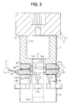
- FIG. 3 is an enlarged schematic cross sectional view of the ultrasonic motor
- FIG. 4 is a plan view of a flexible aluminum-based connective arrangement of the ultrasonic motor
- FIG. 5 is a plan view showing one modification of the flexible aluminum-based connective arrangement of FIG. 4 ;
- FIG. 6 is a plan view showing another modification of the flexible aluminum-based connective arrangement of the FIG. 4 ;
- FIG. 7 is a plan view showing another modification of the flexible aluminum-based connective arrangement of the FIG. 4 ;
- FIG. 8 is a schematic cross sectional view of a previously proposed actuator.
- the actuator 1 includes a housing (serving as a support member) 2 and an ultrasonic motor 3 of a standing wave type.
- the housing 2 is made of a plurality of components and is formed into a generally cylindrical shape.
- a rotatable shaft 5 is rotatably supported by ball bearings 4 at its one end.
- An engaging portion 5 b which has engaging grooves, is formed in the other end (lower end in FIG. 1 ) of the rotatable shaft 5 .
- a flange 5 a which projects radially outward, is arranged adjacent to the engaging portion 5 b in the rotatable shaft 5 .
- the ultrasonic motor 3 includes a stator 11 and a rotor 12 .
- the stator 11 includes an upper metal block 13 , a lower metal block 14 , first and second piezoelectric elements 15 , 16 , a flexible aluminum-based connective arrangement 17 , a bolt 18 and a dielectric collar 19 .
- the upper and lower metal blocks 13 , 14 are formed as first and second aluminum-based metal blocks, which are made of aluminum or its alloy. In this embodiment, the upper and lower metal blocks 13 , 14 are made of an aluminum alloy.
- the upper metal block 13 is formed into a generally cylindrical shape.
- a horn portion 13 a which has an increased inner diameter to amplify a vibration in a top end surface of the upper metal block 13 , is formed in a top part of the upper metal block 13 .
- a female thread 13 b is formed in an inner peripheral surface of the upper metal block 13 except the horn portion 13 a .
- a thin friction material 21 is bonded to the top end surface of the upper metal block 13 .
- the lower metal block 14 is formed into a generally cylindrical shape, which has an inner diameter and an outer diameter similar to the inner diameter and the outer diameter of the upper metal block 13 other than the horn portion 13 a .
- a plurality of slits (recesses) 14 a is formed in a top part (a top part in FIGS. 1 and 2 ) of an outer peripheral surface of the lower metal block 14 .
- the slits 14 a serve as vibration converting portions, which are recessed radially inward in the outer peripheral surface of the lower metal block 14 and generate a torsional vibration in response to a longitudinal vibration generated from the piezoelectric elements 15 , 16 upon application of a high frequency voltage to the piezoelectric elements 15 , 16 .
- the slits 14 a are arranged at generally equal angular intervals in the outer peripheral surface of the lower metal block 14 in the circumferential direction. Furthermore, each slit 14 a is tilted relative a direction that is parallel to an axial direction of the stator 11 .
- a plurality of securing projections 14 b is arranged in the outer peripheral surface of the lower metal block 14 at an axial intermediate location of the lower metal block 14 .
- the securing projections 14 b are arranged at generally equal angular intervals in the circumferential direction and project radially outward to secure the lower metal block 14 to an external member, i.e., the housing 2 .
- a female thread 14 c is formed in an inner peripheral surface (indicated by dotted lines in FIGS. 1 and 3 ) of the lower metal block 14 .
- Each of the first and second piezoelectric elements 15 , 16 is formed into an annular disk shape and has a through hole that axially penetrates through the center of the piezoelectric elements 15 , 16 .
- An inner diameter of each of the first and second piezoelectric elements 15 , 16 is greater than the inner diameter of the upper metal block 13 and of the lower metal block 14 .
- the flexible aluminum-based connective arrangement 17 has a conductive material part 22 (schematically indicated by a bold line in FIG. 3 ), which is made of an aluminum or its alloy that can be recycled together with the material (aluminum alloy in this embodiment) of the upper and lower metal blocks 13 , 14 without requiring separate collection of the recyclable material.
- the conductive material part 22 of the flexible aluminum-based connective arrangement 17 is made of aluminum.
- the flexible aluminum-based connective arrangement 17 further includes a dielectric substrate 23 in addition to the conductive material part 22 .
- the substrate 23 of the present embodiment is made of polyimide resin. A thickness of the substrate 23 of the present embodiment is set to 10 ⁇ m, which can minimize its influence on vibration characteristics of the stator 11 while providing sufficient electric insulation between the conductive material part 22 and the upper and lower metal blocks 13 , 14 .
- FIG. 4 shows a deployed state of the flexible aluminum-based connective arrangement 17 before assembly of the flexible aluminum-based connective arrangement 17 into the stator 11 .
- the flexible aluminum-based connective arrangement 17 is formed as a single integral body and includes a plurality of annular disks 31 - 34 and a plurality of connecting portions 35 - 37 , each of which connects between corresponding two of the disks 31 - 34 .
- the disks 31 - 34 include first to fourth disks 31 - 34
- the connecting portions 35 - 37 include first to third connecting portions 35 - 37 .
- a shape of each disk 31 - 34 corresponds to a shape of an opposed end surface of the piezoelectric element 15 , 16 , which is opposed to the disk 31 - 34 . More specifically, an inner diameter and an outer diameter of each disk 31 - 34 are substantially the same as those of the opposed end of the piezoelectric element 15 , 16 .
- the flexible aluminum-based connective arrangement 17 further includes an extension 38 .
- the extension 38 is electrically connected to a connector C, which in turn is electrically connected to an external device (control device or external power source).
- Sections of the conductive material part 22 which are located in the first to fourth disks 31 - 34 , respectively, form first to fourth electrodes (integrated electrodes) 31 a - 34 a , each of which serves as a conductive member electrically connected to a corresponding one of the first and second piezoelectric elements 15 , 16 .
- the first to third connecting portions 35 - 37 , the first to fourth disks 31 - 34 and the extension 38 are arranged in a single plane. Then, at the time of installing the flexible aluminum-based connective arrangement 17 to the stator 11 , the flexible aluminum-based connective arrangement 17 is bent into a predetermined shape shown in FIGS. 1-3 .
- the first to fourth electrodes 31 a - 34 a are all arranged on one side of the above-described single plane (i.e., on a front side of a plane of FIG. 4 ).
- the first to third connecting portions 35 - 37 are connected to the first to fourth disks 31 - 34 in such a manner that the first to fourth disks 31 - 34 (i.e., the centers of the first to fourth disks 31 - 34 or the centers of the first to fourth electrodes 31 a - 34 a ) are aligned along an imaginary straight line.
- the first connecting portion 35 connects between the first disk 31 and the second disk 32 .
- the second connecting portion 36 connects between the second disk 32 and the third disk 33 .
- the third connecting portion 37 connects between the third disk 33 and the fourth disk 34 .
- the first to third connecting portions 35 - 37 are arranged to align the first to fourth disks 31 - 34 along the imaginary straight line, as described above.
- the extension 38 extends from the centered second connecting portion 36 .
- the first electrode 31 a is connected to the second electrode 32 a by a portion of a first conductive line 22 x of the conductive material part 22 , which is arranged (embedded) in the first connecting portion 35 .
- the second electrode 32 a is connected to a first terminal 38 a , which is exposed at a distal end of the extension 38 (more specifically, at a distal end of the first conductive line 22 x ), through another portion of the first conductive line 22 x of the conductive material part 22 , which is arranged (embedded) in the second connecting portion 36 and in the extension 38 .
- the fourth electrode 34 a is connected to the third electrode 33 a through a portion of a second conductive line 22 y of the conductive material part 22 , which is arranged (embedded) in the third connecting portion 37 .
- the third electrode 33 a is connected to a second terminal 38 b , which is exposed at the distal end of the extension 38 (more specifically, at a distal end of the second conductive line 22 y ), through another portion of the second conductive line 22 y of the conductive material part 22 , which is arranged (embedded) in the second connecting portion 36 and in the extension 38 .
- the first and second electrodes 31 a , 32 a which are arranged on one side (left side in FIG.
- first electrode pair also referred to as a first group of aluminum-based electrodes
- third and fourth electrodes 33 a , 34 a which are arranged on the other side (right side in FIG. 4 ) of the centered second connecting portion 36 , form a second electrode pair (also referred to as a second group of aluminum-based electrodes).
- the first electrode pair i.e., the first and second electrodes 31 a , 32 a
- the second electrode pair (i.e., the third and fourth electrodes 33 a , 34 a ) is electrically connected to the second terminal 38 b through the second conductive line 22 y .
- One of the first electrode pair and the second electrode pair serves as positive electrode pair, and the other one of the first electrode pair and the second electrode pair serves as negative electrode pair.
- the bolt 18 is formed into a generally cylindrical shape, which includes a male thread 18 a in its outer peripheral surface to threadably engage with the female threads 13 b , 14 c.
- the dielectric collar 19 is made of a dielectric resin and is shaped into an annular cylindrical shape.
- An outer diameter of the dielectric collar 19 is generally the same as an inner diameter of the first and second piezoelectric elements 15 , 16 and of the first to fourth disks 31 - 34 .
- An inner diameter of the dielectric collar 19 is generally the same as an outer diameter of the male thread 18 a of the bolt 18 to receive the bolt therethrough.
- the upper metal block 13 and the lower metal block 14 are fastened together by the bolt 18 that axially extends therebetween while the first and second piezoelectric elements 15 , 16 and the first to fourth disks 31 - 34 (first to fourth electrodes 31 a - 34 a ) are arranged between the upper metal block 13 and the lower metal block 14 .
- planar flexible aluminum-based connective arrangement 17 in the deployed state i.e., the state shown in FIG. 4 before installation of the flexible aluminum-based connective arrangement 17 to the stator 11 .
- the upper metal block 13 and the lower metal block 14 are fastened together to form the stator 11 while the first and second piezoelectric elements 15 , 16 , the first to fourth disks 31 - 34 are held between the upper metal block 13 and the lower metal block 14 .
- the fastening process includes a bending and positioning process.
- the first to third connecting portions 35 - 37 are bent such that each of the first to fourth electrodes 31 a - 34 a of the first to fourth disks 31 - 34 engages a corresponding one of the end surfaces of the first and second piezoelectric elements 15 , 16 , and the first to fourth disks 31 - 34 and the first and second piezoelectric elements 15 , 16 are clamped between the upper metal block 13 and the lower metal block 14 .
- the flexible aluminum-based connective arrangement is seen from the one side where the first to fourth electrodes 31 a - 34 a are exposed (FIG.
- the first connecting portion 35 is bent to form a mountain fold, and each of the second and third connecting portions 36 , 37 forms a valley fold.
- the first and second electrodes 31 a , 32 a which form the first electrode pair, are oriented in opposite directions and are thus placed in a back-to-back relationship.
- the third electrode 33 a of the second electrode pair is opposed to the second electrode 32 a
- the fourth electrode 34 a of the second electrode pair is opposed to the first electrode 31 a .
- the fourth electrode 34 a and the first electrode plate 31 a are opposed to one another such that the first piezoelectric element 15 is interposed between the fourth electrode 34 a and the first electrode 31 a .
- the second electrode 32 a and the third electrode 33 a are opposed to one another such that the second piezoelectric element 16 is interposed between the second electrode 32 a and the third electrode 33 a .
- a first axial end of the first piezoelectric element 15 which is adjacent to the upper metal block 13 , directly contacts the fourth aluminum-based electrode 34 a .
- a second axial end of the first piezoelectric element 15 which is opposite from the first axial end of the first piezoelectric element 15 , directly contacts the first aluminum-based electrode 31 a .
- a first axial end of the second piezoelectric element 16 which is adjacent to the second axial end of the first piezoelectric element 15 , directly contacts the second aluminum-based electrode 32 a .
- a second axial end of the second piezoelectric element 16 which is opposite from the first axial end of the second piezoelectric element 16 and is adjacent to the lower metal block 14 , directly contacts the third aluminum-based electrode 33 a.
- the lower metal block 14 , the third disk 33 , the second piezoelectric element 16 , the second disk 32 , the first disk 31 , the first piezoelectric element 15 , the fourth disk 34 , the upper metal block 13 are stacked in this order, and the male thread 18 a of the bolt 18 is threadably engaged with the female threads 13 b , 14 b to fasten them together.
- the first piezoelectric element 15 and the second piezoelectric element 16 are stacked in such a manner that a polarization direction of the first piezoelectric element 15 is opposite from a polarization direction of the second piezoelectric element 16 in the vertical direction in FIG. 3 .
- the dielectric collar 19 is placed between the outer peripheral surface of the male thread 18 a of the bolt 18 and the inner peripheral surfaces of the first and second piezoelectric elements 15 , 16 and of the first to fourth disks 31 - 34 .
- the outer peripheral surface of the bolt 18 is electrically insulated from the inner peripheral surfaces of the first and second piezoelectric elements 15 , 16 and of the first to fourth disks 31 - 34 (first to fourth electrodes 31 a - 34 a ).
- the first and second piezoelectric elements 15 , 16 and the first to fourth electrodes 31 a - 34 a are electrically insulated from the upper and lower metal blocks 13 , 14 by the substrate 23 of the flexible aluminum-based connective arrangement 17 in the axial direction.
- the rotor 12 is made of iron or its alloy.
- the rotor 12 is formed into a generally cylindrical shape and has an outer diameter, which is larger than the outer diameter of the upper metal block 13 and the outer diameter of the lower metal block 14 .
- the rotor slits are arranged at equal angular intervals in a circumferential direction.
- the rotor 12 is slidably and rotatably urged against a top end surface of the stator 11 , i.e., against the top end surface of the upper metal block 13 (the friction material 21 ).
- an engaging recess 12 a which is engageable with the engaging portion 5 b of the rotatable shaft 5 , is formed in one end (upper end in FIG. 3 ) of the rotor 12 .
- the rotor 12 is connected to the rotatable shaft 5 in such a manner that the rotor 12 is non-rotatable to the rotatable shaft 5 and is axially movable relative to the engaging portion 5 b .
- a Belleville spring 41 is interposed between the flange 5 a of the rotatable shaft 5 and the rotor 12 .
- the stator 11 is received in the housing 2 , and the securing projections 14 b of the stator 11 is connected to the housing 2 through a connecting member 42 to secure the stator 11 to the housing 2 in such a manner that the top end surface of the stator 11 has pressure engagement with the rotor 12 (compressing the Belleville spring 41 ).
- the distal end of the extension 38 i.e., the first and second terminals 38 a , 38 b ( FIG. 4 ) of the flexible aluminum-based connective arrangement 17 is placed outside of the housing 2 .
- the first and second terminals 38 a , 38 b are received and held in a housing of the connector C to serve as connection terminals of the connector C.
- the control device (not shown) when the control device (not shown) is operated to apply a high frequency voltage to the first to fourth electrodes 31 a - 34 a (i.e., between the first electrode pair and the second electrode pair) through the first and second terminals 38 a , 38 b , a relatively large longitudinal vibration is generated by the first and second piezoelectric elements 15 , 16 (a degree of the longitudinal vibration is a sum of vibrations of the first and second piezoelectric elements 15 , 16 ). Then, torsional vibrations are generated by the slits 14 a of the stator 11 and the rotor slits (not shown) of the rotor 12 in response to the longitudinal vibration.
- the rotor 12 is rotated by lift force generated by a longitudinal vibration component and a rotational drive force generated by a torsional vibration component, and the rotatable shaft 5 is rotated together with the rotor 12 .
- the conductive members which are electrically connected to the first and second piezoelectric elements 15 , 16 , include the first to fourth aluminum-based electrodes 31 a - 34 a of the flexible aluminum-based connective arrangement 17 that is clamped together with the first and second piezoelectric elements 15 , 16 between the upper metal block 13 and the lower metal block 14 .
- it is not required to remove copper (more specifically, electrode plates made of copper or its alloy) from the stator 11 , which cannot be easily disassembled.
- a recyclability of the actuator 1 (ultrasonic motor 3 ) is further improved.
- the flexible aluminum-based connective arrangement 17 integrally includes the first to fourth disks 31 - 34 , each of which is shaped to correspond with the end surface of the corresponding piezoelectric element 15 , 16 , and the first to third connecting portions 35 - 37 , each of which connects between the corresponding disks 31 , 34 .
- the number of components can be minimized.
- the flexible aluminum-based connective arrangement 17 further integrally includes the extension 38 , which is connected to the connector C to be connected to the external device (control device).
- the number of components can be further minimized.
- it is not required to solder electrical wires to the electrode plates, and thus there is no soldering related failure, such as cracking at the soldered portions.
- the first to third connecting portions 35 - 37 which are originally formed as the flat component together with first to fourth disks 31 - 34 , are bent in the bending and positioning process.
- the flexible aluminum-based connective arrangement 17 can be more easily formed in the flexible aluminum-based conductive arrangement manufacturing process in comparison to the case where the flexible aluminum-based connective arrangement 17 is formed to have, for example, steps at the unassembled component state (FIG. 4 ).
- the first to fourth electrodes 31 a - 34 a are all arranged on one side of the single plane (on the front side of the plane of FIG. 4 ), so that manufacturing of the first to fourth electrodes 31 a - 34 a are eased in comparison to the case where one or more of the first to fourth electrodes 31 a - 34 a is arranged on the one side of the single plane, and the rest of the first to fourth electrodes 31 a - 34 a is arranged on the other side of the single plane.
- the first and second terminals 38 a , 38 b are all arranged on the one side of the single plane (on the front side of the plane of FIG. 4 ), so that the first and second terminals 38 a , 38 b can be manufactured together with the first to fourth electrodes 31 a - 34 a in a single process.
- the manufacturing of the flexible aluminum-based connective arrangement 17 is eased.
- the first and second electrodes 31 a , 32 a which are arranged on one side of the centered second connecting portion 36 , form the first electrode pair
- the third and fourth electrodes 33 a , 34 a which are arranged on the other side of the centered second connecting portion 36 , form the second electrode pair.
- the extension 38 extends from the centered second connecting portion 36 .
- the first to third connecting portions 35 - 37 connect the first to fourth disks 31 , 34 along the straight line.
- bending lines which are indicated by dot-dot-dash lines in FIG. 4 , are oriented in the same direction (top-bottom direction in FIG. 4 ).
- the bending process of the first to third connecting portions 35 - 37 is eased, and the first to fourth disks 31 - 34 can be easily arranged.
- the first and second piezoelectric elements 15 , 16 and the first to fourth electrodes 31 a - 34 a are electrically insulated from the upper and lower metal blocks 13 , 14 by the substrate 23 of the flexible aluminum-based connective arrangement 17 .
- any other insulating means is not required.
- a dielectric resin material 94 or the like which is indicated by a solid bold line in FIG. 8 , is required between the securing projections 83 b and the connecting member 92 .
- a separate engaging member 96 made of a dielectric resin material is secured to a rotatable shaft 95 , and the rotatable shaft 95 is connected to the rotor 82 through the engaging member 96 .
- the separate dielectric resin material 94 and the separate dielectric engaging member 96 are not required.
- the flexible aluminum-based connective arrangement 17 of the above embodiment can be changed to any other appropriate shape as long as the conductive material part 22 of the flexible aluminum-based connective arrangement 17 is made of aluminum or its alloy.
- the flexible aluminum-based connective arrangement 17 can be modified to any one of flexible aluminum-based connective arrangements 51 , 61 , 71 shown in FIGS. 5 to 7 .
- first to third connecting portions 52 - 54 connect first to fourth annular disks 55 - 58 (first to fourth electrodes 55 a - 58 a ) along a line, more specifically, along a bent line. More specifically, in the present instance, the first to third connecting portions 52 - 54 connect the first to fourth disks 55 - 58 such that the first to fourth disks 55 - 58 are arranged in corners, respectively, of an imaginary quadrangle.
- first to third connecting portions 62 - 64 connect first to fourth annular disks 65 - 68 (first to fourth electrodes 65 a - 68 a ) along a line, more specifically, along a bent line. More specifically, in the present instance, the first to third connecting portions 62 - 64 connect the first to fourth disks 65 - 68 such that an imaginary line, which connects a center of each of the first to fourth disks 65 - 68 , forms a crank line that is bent twice to define two right angles.
- first to third connecting portions 72 - 74 connect first to fourth annular disks 75 - 78 (first to fourth electrodes 75 a - 78 a ) along a line, more specifically, along a bent line. More specifically, in the present instance, the first to third connecting portions 72 - 74 connect the first to fourth disks 75 - 78 such that an imaginary straight line, which extends through a center of the first disk 75 and a center of the second disk 76 , defines a right angle with an imaginary straight line, which extends through each center of the second to fourth disks 76 - 78 .
- any one of the flexible aluminum-based connective arrangements 17 , 51 , 61 , 71 can be selected based on a desired size and/or shape that is manufacturable with a designated manufacturing apparatus.
- the extension 38 which is connected to the connector C, is formed integrally with the flexible aluminum-based connective arrangement 17 .
- a separate wiring can be used to connect between the flexible aluminum-based connective arrangement and the connector C.
- the first to fourth electrodes 31 a - 34 a are all arranged on the one side of the single plane.
- one or more of the first to fourth electrodes 31 a - 34 a can be arranged on the one side of the single plane, and the rest of the first to fourth electrodes 31 a - 34 a can be arranged on the other side of the single plane, if desired.
- the disk which is interposed between the first piezoelectric element 15 and the second piezoelectric element 16 , can have two electrodes on its axial end surfaces, respectively, to engage with the first and second piezoelectric elements 15 , 16 , respectively. With this arrangement, the number of the disks can be reduced to three.
- the extension 38 extends from the centered second connecting portion 36 .
- the extension can extend from any other appropriate location, such as from the first disk 31 or the first connecting portion 35 when the extension extends from the first disk 31 or the first connecting portion 35 , an additional electrical wiring to the second electrode pair (i.e., the third and fourth electrodes 33 , 34 ) needs to be provided at an outer peripheral of the second disk 32 .
- the single flexible aluminum-based connective arrangement 17 is used.
- more that one flexible aluminum-based connective arrangement can be used.
- one flexible aluminum-based connective arrangement which includes the first electrode pair (i.e., the first and second electrodes 31 a , 32 a ), and another flexible aluminum-based connective arrangement, which includes the second electrode pair (i.e., the third and fourth electrodes 33 a , 34 a ) can be provided.
- the rotor 12 is made of iron or its alloy.
- the rotor 12 can be made of aluminum or its alloy. In this way, collection of the recyclable material from the stator 11 needs not be performed separately from collection of the recyclable material from the rotor 12 . This allows an improvement in the recyclability of the material.
- the present invention is embodied in the ultrasonic motor, which has the first and second piezoelectric elements 15 , 16 .
- the present invention can be embodied in an ultrasonic motor, which has only one piezoelectric element or more than two piezoelectric elements. In such a case, the structure (e.g., the number of the disks) of the flexible aluminum-based connective arrangement 17 needs to be changed in an appropriate manner.
- the first to fourth electrodes 31 a - 34 a which are electrically connected to the first and second piezoelectric elements 15 , 16 , are used as the voltage supply electrodes.
- one or more of the first to fourth electrodes can be used in any other usage, for example, can be used as a feedback electrode, which conducts electrical voltage generated in the piezoelectric elements to the control device).
- the bolt 18 of the above embodiment can be changed to any other fastening member, such as one that has bendable ends to be bent to securely connect between the components.
Abstract
A stator includes first and second piezoelectric elements, a flexible aluminum-based connective arrangement and upper and lower aluminum-based metal blocks. The flexible aluminum-based connective arrangement includes first to fourth aluminum-based electrodes, which apply a voltage to the piezoelectric elements to generate a vibration. Each aluminum-based electrode is made of one of aluminum and an aluminum alloy and directly contacts a corresponding one of axial ends of the piezoelectric elements. Each aluminum-based metal block is made of one of aluminum and an aluminum alloy. The piezoelectric elements and the aluminum-based electrodes are interposed between the aluminum-based metal blocks.
Description
This application is based on and incorporates herein by reference Japanese Patent Application No. 2003-33459 filed on Feb. 12, 2003.
1. Field of the Invention
The present invention relates to an ultrasonic motor and a manufacturing method thereof.
2. Description of Related Art
Various Langevin type ultrasonic motors, each of which has a generally cylindrical shape and generates a standing wave, have been known (e.g., one disclosed in U.S. Pat. No. 6,018,213 corresponding to Japanese Unexamined Patent Publication No. 11-155288). FIG. 8 shows an actuator having one previously proposed Langevin type ultrasonic motor. The previously proposed ultrasonic motor includes a stator 81 and a rotor 82. The stator 81 is formed into a generally cylindrical shape. Furthermore, the stator 81 includes an upper metal block 89, a first electrode plate 88, a first piezoelectric element 87, a second electrode plate 86, a second piezoelectric element 85, a third electrode plate 84 and a lower metal block 83, which are stacked in this order from top to bottom of the stator 81 and are fastened by a bolt 90 that extends therethrough. A plurality of slits 83 a is formed in an outer peripheral surface of the lower metal block 83 in such a manner that the slits 83 a are circumferentially arranged at generally equal angular intervals. The slits 83 a generate a torsional vibration in response to a longitudinal vibration generated by the first and second piezoelectric elements 87, 85. The rotor 82 is formed into a generally cylindrical shape. The rotor 82 is urged against a top end surface of the stator 81, i.e., a top end surface of the upper mental block 89 by a Belleville spring 91.
When a high frequency voltage is applied to the first to third electrode plates 88, 86, 84, a longitudinal vibration is generated by the first and second piezoelectric elements 87, 85, and a torsional vibration is generated by the slits 83 a in response to the longitudinal vibration. Thus, the rotor 82 is rotated by these vibrations.
In the previously proposed ultrasonic motor shown in FIG. 8 , the first to third electrode plates 88, 86, 84, which are made of copper or its alloy, are used as conductive members that are electrically connected to the first and second piezoelectric elements 87, 85. The lower and upper metal blocks 83, 89 are made of aluminum or its alloy. In order to perform appropriate recycling of materials of the ultrasonic motor, the first to third electrode plates 88, 86, 84 (copper or its alloy) need to be removed from the stator 81 (aluminum or its alloy). However, in the stator 81, the first to third electrode plates 88, 86, 84 are fastened between the lower metal block 83 and the upper metal block 89, so that it is difficult to remove the first to third electrode plates 88, 86, 84 from the lower and upper metal blocks 83, 89, resulting in low recyclability of the materials.
The present invention addresses the above disadvantages. Thus, it is an objective of the present invention to provide an ultrasonic motor having improved recyclability of materials of the ultrasonic motor. It is another objective of the present invention to provide a manufacturing method of such an ultrasonic motor.
To achieve the objectives of the present invention, there is provided an ultrasonic motor including a stator and a rotor. The stator includes at least one piezoelectric element, a flexible aluminum-based connective arrangement and a plurality of aluminum-based metal blocks. The flexible aluminum-based connective arrangement includes a plurality of aluminum-based electrodes, which apply a voltage to the at least one piezoelectric element to generate a vibration from the at least one piezoelectric element. Each aluminum-based electrode is made of one of aluminum and an aluminum alloy and directly contacts a corresponding one of axial ends of the at least one piezoelectric element. Each aluminum-based metal block is made of one of aluminum and an aluminum alloy. The at least one piezoelectric element and the aluminum-based electrodes are interposed between corresponding two of the aluminum-based metal blocks. The rotor is slidably and rotatably urged against the stator. The rotor is rotated upon generation of the vibration in the stator.
To achieve the objectives of the present invention, there is further provided a method for manufacturing an ultrasonic motor. In the method, a flexible aluminum-based connective arrangement is first formed. The flexible aluminum-based connective arrangement is planar and includes a plurality of aluminum-based electrodes, each of which is made of one of aluminum and an aluminum alloy. Then, a stator is constructed by assembling the flexible aluminum-based connective arrangement, at least one piezoelectric element and a plurality of aluminum-based metal blocks. Each aluminum-based metal block is made of one of aluminum and an aluminum alloy. At this stage, the flexible aluminum-based connective arrangement is bent, and each aluminum-based electrode directly contacts a corresponding one of axial ends of the at least one piezoelectric element. Thereafter, a rotor is installed to the stator in such a manner that the rotor is slidably and rotatably urged against the stator.
The invention, together with additional objectives, features and advantages thereof, will be best understood from the following description, the appended claims and the accompanying drawings in which:
An actuator according to an embodiment of the present invention will be described with reference to FIGS. 1 to 4. As shown in FIG. 1 , the actuator 1 includes a housing (serving as a support member) 2 and an ultrasonic motor 3 of a standing wave type.
The housing 2 is made of a plurality of components and is formed into a generally cylindrical shape. In one end (upper end in FIG. 1 ) of the housing 2, a rotatable shaft 5 is rotatably supported by ball bearings 4 at its one end. An engaging portion 5 b, which has engaging grooves, is formed in the other end (lower end in FIG. 1 ) of the rotatable shaft 5. A flange 5 a, which projects radially outward, is arranged adjacent to the engaging portion 5 b in the rotatable shaft 5.
As shown in FIGS. 1 and 3 , the ultrasonic motor 3 includes a stator 11 and a rotor 12. The stator 11 includes an upper metal block 13, a lower metal block 14, first and second piezoelectric elements 15, 16, a flexible aluminum-based connective arrangement 17, a bolt 18 and a dielectric collar 19.
The upper and lower metal blocks 13, 14 are formed as first and second aluminum-based metal blocks, which are made of aluminum or its alloy. In this embodiment, the upper and lower metal blocks 13, 14 are made of an aluminum alloy. The upper metal block 13 is formed into a generally cylindrical shape. A horn portion 13 a, which has an increased inner diameter to amplify a vibration in a top end surface of the upper metal block 13, is formed in a top part of the upper metal block 13. A female thread 13 b is formed in an inner peripheral surface of the upper metal block 13 except the horn portion 13 a. A thin friction material 21 is bonded to the top end surface of the upper metal block 13.
The lower metal block 14 is formed into a generally cylindrical shape, which has an inner diameter and an outer diameter similar to the inner diameter and the outer diameter of the upper metal block 13 other than the horn portion 13 a. A plurality of slits (recesses) 14 a is formed in a top part (a top part in FIGS. 1 and 2 ) of an outer peripheral surface of the lower metal block 14. The slits 14 a serve as vibration converting portions, which are recessed radially inward in the outer peripheral surface of the lower metal block 14 and generate a torsional vibration in response to a longitudinal vibration generated from the piezoelectric elements 15, 16 upon application of a high frequency voltage to the piezoelectric elements 15, 16. The slits 14 a are arranged at generally equal angular intervals in the outer peripheral surface of the lower metal block 14 in the circumferential direction. Furthermore, each slit 14 a is tilted relative a direction that is parallel to an axial direction of the stator 11.
A plurality of securing projections 14 b is arranged in the outer peripheral surface of the lower metal block 14 at an axial intermediate location of the lower metal block 14. The securing projections 14 b are arranged at generally equal angular intervals in the circumferential direction and project radially outward to secure the lower metal block 14 to an external member, i.e., the housing 2. A female thread 14 c is formed in an inner peripheral surface (indicated by dotted lines in FIGS. 1 and 3 ) of the lower metal block 14.
Each of the first and second piezoelectric elements 15, 16 is formed into an annular disk shape and has a through hole that axially penetrates through the center of the piezoelectric elements 15, 16. An inner diameter of each of the first and second piezoelectric elements 15, 16 is greater than the inner diameter of the upper metal block 13 and of the lower metal block 14.
The flexible aluminum-based connective arrangement 17 has a conductive material part 22 (schematically indicated by a bold line in FIG. 3), which is made of an aluminum or its alloy that can be recycled together with the material (aluminum alloy in this embodiment) of the upper and lower metal blocks 13, 14 without requiring separate collection of the recyclable material. In the present embodiment, the conductive material part 22 of the flexible aluminum-based connective arrangement 17 is made of aluminum. The flexible aluminum-based connective arrangement 17 further includes a dielectric substrate 23 in addition to the conductive material part 22. The substrate 23 of the present embodiment is made of polyimide resin. A thickness of the substrate 23 of the present embodiment is set to 10 μm, which can minimize its influence on vibration characteristics of the stator 11 while providing sufficient electric insulation between the conductive material part 22 and the upper and lower metal blocks 13, 14.
In the deployed state, i.e., in the state before installation of the flexible aluminum-based connective arrangement 17 to the stator 11, the first to third connecting portions 35-37, the first to fourth disks 31-34 and the extension 38 are arranged in a single plane. Then, at the time of installing the flexible aluminum-based connective arrangement 17 to the stator 11, the flexible aluminum-based connective arrangement 17 is bent into a predetermined shape shown in FIGS. 1-3 .
The first to fourth electrodes 31 a-34 a are all arranged on one side of the above-described single plane (i.e., on a front side of a plane of FIG. 4). The first to third connecting portions 35-37 are connected to the first to fourth disks 31-34 in such a manner that the first to fourth disks 31-34 (i.e., the centers of the first to fourth disks 31-34 or the centers of the first to fourth electrodes 31 a-34 a) are aligned along an imaginary straight line.
Specifically, the first connecting portion 35 connects between the first disk 31 and the second disk 32. The second connecting portion 36 connects between the second disk 32 and the third disk 33. The third connecting portion 37 connects between the third disk 33 and the fourth disk 34. Furthermore, in the present embodiment, the first to third connecting portions 35-37 are arranged to align the first to fourth disks 31-34 along the imaginary straight line, as described above. The extension 38 extends from the centered second connecting portion 36. The first electrode 31 a is connected to the second electrode 32 a by a portion of a first conductive line 22 x of the conductive material part 22, which is arranged (embedded) in the first connecting portion 35. The second electrode 32 a is connected to a first terminal 38 a, which is exposed at a distal end of the extension 38 (more specifically, at a distal end of the first conductive line 22 x), through another portion of the first conductive line 22 x of the conductive material part 22, which is arranged (embedded) in the second connecting portion 36 and in the extension 38. The fourth electrode 34 a is connected to the third electrode 33 a through a portion of a second conductive line 22 y of the conductive material part 22, which is arranged (embedded) in the third connecting portion 37. The third electrode 33 a is connected to a second terminal 38 b, which is exposed at the distal end of the extension 38 (more specifically, at a distal end of the second conductive line 22 y), through another portion of the second conductive line 22 y of the conductive material part 22, which is arranged (embedded) in the second connecting portion 36 and in the extension 38. In the present embodiment, the first and second electrodes 31 a, 32 a, which are arranged on one side (left side in FIG. 4 ) of the centered second connecting portion 36, form a first electrode pair (also referred to as a first group of aluminum-based electrodes), and the third and fourth electrodes 33 a, 34 a, which are arranged on the other side (right side in FIG. 4 ) of the centered second connecting portion 36, form a second electrode pair (also referred to as a second group of aluminum-based electrodes). The first electrode pair (i.e., the first and second electrodes 31 a, 32 a) is electrically connected to the first terminal 38 a through the first conductive line 22 x. The second electrode pair (i.e., the third and fourth electrodes 33 a, 34 a) is electrically connected to the second terminal 38 b through the second conductive line 22 y. One of the first electrode pair and the second electrode pair serves as positive electrode pair, and the other one of the first electrode pair and the second electrode pair serves as negative electrode pair.
The bolt 18 is formed into a generally cylindrical shape, which includes a male thread 18 a in its outer peripheral surface to threadably engage with the female threads 13 b, 14 c.
The dielectric collar 19 is made of a dielectric resin and is shaped into an annular cylindrical shape. An outer diameter of the dielectric collar 19 is generally the same as an inner diameter of the first and second piezoelectric elements 15, 16 and of the first to fourth disks 31-34. An inner diameter of the dielectric collar 19 is generally the same as an outer diameter of the male thread 18 a of the bolt 18 to receive the bolt therethrough.
The upper metal block 13 and the lower metal block 14 are fastened together by the bolt 18 that axially extends therebetween while the first and second piezoelectric elements 15, 16 and the first to fourth disks 31-34 (first to fourth electrodes 31 a-34 a) are arranged between the upper metal block 13 and the lower metal block 14.
Manufacturing of the stator 11 will be described further.
In a flexible aluminum-based conductive arrangement manufacturing process, the planar flexible aluminum-based connective arrangement 17 in the deployed state (i.e., the state shown in FIG. 4 before installation of the flexible aluminum-based connective arrangement 17 to the stator 11) is formed.
Then, in a fastening process, the upper metal block 13 and the lower metal block 14 are fastened together to form the stator 11 while the first and second piezoelectric elements 15, 16, the first to fourth disks 31-34 are held between the upper metal block 13 and the lower metal block 14.
More specifically, the fastening process includes a bending and positioning process.
In the bending and positioning process, the first to third connecting portions 35-37 are bent such that each of the first to fourth electrodes 31 a-34 a of the first to fourth disks 31-34 engages a corresponding one of the end surfaces of the first and second piezoelectric elements 15, 16, and the first to fourth disks 31-34 and the first and second piezoelectric elements 15, 16 are clamped between the upper metal block 13 and the lower metal block 14. In the present embodiment, when the flexible aluminum-based connective arrangement is seen from the one side where the first to fourth electrodes 31 a-34 a are exposed (FIG. 4), the first connecting portion 35 is bent to form a mountain fold, and each of the second and third connecting portions 36, 37 forms a valley fold. In this way, as shown in FIG. 3 , the first and second electrodes 31 a, 32 a, which form the first electrode pair, are oriented in opposite directions and are thus placed in a back-to-back relationship. Also, the third electrode 33 a of the second electrode pair is opposed to the second electrode 32 a, and the fourth electrode 34 a of the second electrode pair is opposed to the first electrode 31 a. Furthermore, the fourth electrode 34 a and the first electrode plate 31 a are opposed to one another such that the first piezoelectric element 15 is interposed between the fourth electrode 34 a and the first electrode 31 a. In addition, the second electrode 32 a and the third electrode 33 a are opposed to one another such that the second piezoelectric element 16 is interposed between the second electrode 32 a and the third electrode 33 a. More specifically, a first axial end of the first piezoelectric element 15, which is adjacent to the upper metal block 13, directly contacts the fourth aluminum-based electrode 34 a. A second axial end of the first piezoelectric element 15, which is opposite from the first axial end of the first piezoelectric element 15, directly contacts the first aluminum-based electrode 31 a. A first axial end of the second piezoelectric element 16, which is adjacent to the second axial end of the first piezoelectric element 15, directly contacts the second aluminum-based electrode 32 a. A second axial end of the second piezoelectric element 16, which is opposite from the first axial end of the second piezoelectric element 16 and is adjacent to the lower metal block 14, directly contacts the third aluminum-based electrode 33 a.
Furthermore, in the fastening process, the lower metal block 14, the third disk 33, the second piezoelectric element 16, the second disk 32, the first disk 31, the first piezoelectric element 15, the fourth disk 34, the upper metal block 13 are stacked in this order, and the male thread 18 a of the bolt 18 is threadably engaged with the female threads 13 b, 14 b to fasten them together. At this time, the first piezoelectric element 15 and the second piezoelectric element 16 are stacked in such a manner that a polarization direction of the first piezoelectric element 15 is opposite from a polarization direction of the second piezoelectric element 16 in the vertical direction in FIG. 3. Furthermore, the dielectric collar 19 is placed between the outer peripheral surface of the male thread 18 a of the bolt 18 and the inner peripheral surfaces of the first and second piezoelectric elements 15, 16 and of the first to fourth disks 31-34. Thus, the outer peripheral surface of the bolt 18 is electrically insulated from the inner peripheral surfaces of the first and second piezoelectric elements 15, 16 and of the first to fourth disks 31-34 (first to fourth electrodes 31 a-34 a). Also, at this stage, the first and second piezoelectric elements 15, 16 and the first to fourth electrodes 31 a-34 a are electrically insulated from the upper and lower metal blocks 13, 14 by the substrate 23 of the flexible aluminum-based connective arrangement 17 in the axial direction.
The rotor 12 is made of iron or its alloy. The rotor 12 is formed into a generally cylindrical shape and has an outer diameter, which is larger than the outer diameter of the upper metal block 13 and the outer diameter of the lower metal block 14. A plurality of undepicted rotor slits (recesses), which generate a torsional vibration in response to the longitudinal vibration, is formed in an outer peripheral surface of the rotor 12. The rotor slits are arranged at equal angular intervals in a circumferential direction. The rotor 12 is slidably and rotatably urged against a top end surface of the stator 11, i.e., against the top end surface of the upper metal block 13 (the friction material 21).
More specifically, an engaging recess 12 a, which is engageable with the engaging portion 5 b of the rotatable shaft 5, is formed in one end (upper end in FIG. 3 ) of the rotor 12. When the engaging portion 5 b is fitted into the engaging recess 12 a, the rotor 12 is connected to the rotatable shaft 5 in such a manner that the rotor 12 is non-rotatable to the rotatable shaft 5 and is axially movable relative to the engaging portion 5 b. Furthermore, at this time, a Belleville spring 41 is interposed between the flange 5 a of the rotatable shaft 5 and the rotor 12. The stator 11 is received in the housing 2, and the securing projections 14 b of the stator 11 is connected to the housing 2 through a connecting member 42 to secure the stator 11 to the housing 2 in such a manner that the top end surface of the stator 11 has pressure engagement with the rotor 12 (compressing the Belleville spring 41). At this state, the distal end of the extension 38, i.e., the first and second terminals 38 a, 38 b (FIG. 4 ) of the flexible aluminum-based connective arrangement 17 is placed outside of the housing 2. The first and second terminals 38 a, 38 b are received and held in a housing of the connector C to serve as connection terminals of the connector C.
In the thus constructed actuator 1 (ultrasonic motor 3), when the control device (not shown) is operated to apply a high frequency voltage to the first to fourth electrodes 31 a-34 a (i.e., between the first electrode pair and the second electrode pair) through the first and second terminals 38 a, 38 b, a relatively large longitudinal vibration is generated by the first and second piezoelectric elements 15, 16 (a degree of the longitudinal vibration is a sum of vibrations of the first and second piezoelectric elements 15, 16). Then, torsional vibrations are generated by the slits 14 a of the stator 11 and the rotor slits (not shown) of the rotor 12 in response to the longitudinal vibration. Thus, the rotor 12 is rotated by lift force generated by a longitudinal vibration component and a rotational drive force generated by a torsional vibration component, and the rotatable shaft 5 is rotated together with the rotor 12.
Next, advantages of the above embodiment will be described.
(1) The conductive members, which are electrically connected to the first and second piezoelectric elements 15, 16, include the first to fourth aluminum-based electrodes 31 a-34 a of the flexible aluminum-based connective arrangement 17 that is clamped together with the first and second piezoelectric elements 15, 16 between the upper metal block 13 and the lower metal block 14. Thus, at the time of recycling (in a recycle process), unlike the previously proposed ultrasonic motor, it is not required to remove copper (more specifically, electrode plates made of copper or its alloy) from the stator 11, which cannot be easily disassembled. Thus, a recyclability of the actuator 1 (ultrasonic motor 3) is further improved.
(2) The flexible aluminum-based connective arrangement 17 integrally includes the first to fourth disks 31-34, each of which is shaped to correspond with the end surface of the corresponding piezoelectric element 15, 16, and the first to third connecting portions 35-37, each of which connects between the corresponding disks 31, 34. Thus, the number of components can be minimized.
(3) The flexible aluminum-based connective arrangement 17 further integrally includes the extension 38, which is connected to the connector C to be connected to the external device (control device). Thus, the number of components can be further minimized. In addition, unlike the previously proposed ultrasonic motor, it is not required to solder electrical wires to the electrode plates, and thus there is no soldering related failure, such as cracking at the soldered portions.
(4) The first to third connecting portions 35-37, which are originally formed as the flat component together with first to fourth disks 31-34, are bent in the bending and positioning process. Thus, the flexible aluminum-based connective arrangement 17 can be more easily formed in the flexible aluminum-based conductive arrangement manufacturing process in comparison to the case where the flexible aluminum-based connective arrangement 17 is formed to have, for example, steps at the unassembled component state (FIG. 4).
(5) The first to fourth electrodes 31 a-34 a are all arranged on one side of the single plane (on the front side of the plane of FIG. 4), so that manufacturing of the first to fourth electrodes 31 a-34 a are eased in comparison to the case where one or more of the first to fourth electrodes 31 a-34 a is arranged on the one side of the single plane, and the rest of the first to fourth electrodes 31 a-34 a is arranged on the other side of the single plane. Furthermore, in the present embodiment, the first and second terminals 38 a, 38 b are all arranged on the one side of the single plane (on the front side of the plane of FIG. 4), so that the first and second terminals 38 a, 38 b can be manufactured together with the first to fourth electrodes 31 a-34 a in a single process. Thus, the manufacturing of the flexible aluminum-based connective arrangement 17 is eased.
(6) The first and second electrodes 31 a, 32 a, which are arranged on one side of the centered second connecting portion 36, form the first electrode pair, and the third and fourth electrodes 33 a, 34 a, which are arranged on the other side of the centered second connecting portion 36, form the second electrode pair. Furthermore, the extension 38 extends from the centered second connecting portion 36. Thus, the electrical wiring (i.e., the conductive lines 22 x, 22 y) to the two types of electrodes (first and second electrode pairs) can be easily arranged and can be minimized. More specifically, for example, when the extension extends from the first connecting portion 35 located on the one side of the centered second connecting portion 36, electrical wiring to the second electrode pair (i.e., the third and fourth electrodes 33 a, 34 a) located on the other side of the centered second connecting portion 36 becomes more complicated and elongated. However, with the above symmetrical arrangement of the electrodes, the electrical wiring can be more easily arranged and minimized.
(7) The first to third connecting portions 35-37 connect the first to fourth disks 31, 34 along the straight line. With this arrangement, bending lines, which are indicated by dot-dot-dash lines in FIG. 4 , are oriented in the same direction (top-bottom direction in FIG. 4). Thus, the bending process of the first to third connecting portions 35-37 is eased, and the first to fourth disks 31-34 can be easily arranged.
(8) The first and second piezoelectric elements 15, 16 and the first to fourth electrodes 31 a-34 a are electrically insulated from the upper and lower metal blocks 13, 14 by the substrate 23 of the flexible aluminum-based connective arrangement 17. Thus, when the upper and lower metal blocks 13, 14 are secured to the housing 2, any other insulating means is not required. More specifically, with reference to FIG. 8 , in the previously proposed ultrasonic motor, when the securing projections 83 b are secured to the housing 93 through a connecting member 92, a dielectric resin material 94 or the like, which is indicated by a solid bold line in FIG. 8 , is required between the securing projections 83 b and the connecting member 92. Furthermore, in the previously proposed ultrasonic motor depicted in FIG. 8 , a separate engaging member 96 made of a dielectric resin material is secured to a rotatable shaft 95, and the rotatable shaft 95 is connected to the rotor 82 through the engaging member 96. Contrary to this, in the case of the actuator 1 according to the present embodiment, the separate dielectric resin material 94 and the separate dielectric engaging member 96 are not required.
The above embodiment can be modified as follows.
The flexible aluminum-based connective arrangement 17 of the above embodiment can be changed to any other appropriate shape as long as the conductive material part 22 of the flexible aluminum-based connective arrangement 17 is made of aluminum or its alloy. For example, the flexible aluminum-based connective arrangement 17 can be modified to any one of flexible aluminum-based connective arrangements 51, 61, 71 shown in FIGS. 5 to 7.
With reference to FIG. 5 , in the flexible aluminum-based connective arrangement 51, first to third connecting portions 52-54 connect first to fourth annular disks 55-58 (first to fourth electrodes 55 a-58 a) along a line, more specifically, along a bent line. More specifically, in the present instance, the first to third connecting portions 52-54 connect the first to fourth disks 55-58 such that the first to fourth disks 55-58 are arranged in corners, respectively, of an imaginary quadrangle.
With reference to FIG. 6 , in the flexible aluminum-based connective arrangement 61, first to third connecting portions 62-64 connect first to fourth annular disks 65-68 (first to fourth electrodes 65 a-68 a) along a line, more specifically, along a bent line. More specifically, in the present instance, the first to third connecting portions 62-64 connect the first to fourth disks 65-68 such that an imaginary line, which connects a center of each of the first to fourth disks 65-68, forms a crank line that is bent twice to define two right angles.
With reference to FIG. 7 , in the flexible aluminum-based connective arrangement 71, first to third connecting portions 72-74 connect first to fourth annular disks 75-78 (first to fourth electrodes 75 a-78 a) along a line, more specifically, along a bent line. More specifically, in the present instance, the first to third connecting portions 72-74 connect the first to fourth disks 75-78 such that an imaginary straight line, which extends through a center of the first disk 75 and a center of the second disk 76, defines a right angle with an imaginary straight line, which extends through each center of the second to fourth disks 76-78.
Even with the above modifications (FIGS. 5-7), advantages similar to those discussed in the above sections (1)-(6) and (8) can be achieved. Furthermore, in order to improve productivity, any one of the flexible aluminum-based connective arrangements 17, 51, 61, 71 can be selected based on a desired size and/or shape that is manufacturable with a designated manufacturing apparatus.
In the above embodiment, the extension 38, which is connected to the connector C, is formed integrally with the flexible aluminum-based connective arrangement 17. Alternatively, a separate wiring can be used to connect between the flexible aluminum-based connective arrangement and the connector C.
In the above embodiment, the first to fourth electrodes 31 a-34 a are all arranged on the one side of the single plane. However, one or more of the first to fourth electrodes 31 a-34 a can be arranged on the one side of the single plane, and the rest of the first to fourth electrodes 31 a-34 a can be arranged on the other side of the single plane, if desired. Furthermore, the disk, which is interposed between the first piezoelectric element 15 and the second piezoelectric element 16, can have two electrodes on its axial end surfaces, respectively, to engage with the first and second piezoelectric elements 15, 16, respectively. With this arrangement, the number of the disks can be reduced to three.
In the above embodiment, the extension 38 extends from the centered second connecting portion 36. Alternatively, the extension can extend from any other appropriate location, such as from the first disk 31 or the first connecting portion 35 when the extension extends from the first disk 31 or the first connecting portion 35, an additional electrical wiring to the second electrode pair (i.e., the third and fourth electrodes 33, 34) needs to be provided at an outer peripheral of the second disk 32.
In the above embodiment, the single flexible aluminum-based connective arrangement 17 is used. Alternatively, more that one flexible aluminum-based connective arrangement can be used. For example, one flexible aluminum-based connective arrangement, which includes the first electrode pair (i.e., the first and second electrodes 31 a, 32 a), and another flexible aluminum-based connective arrangement, which includes the second electrode pair (i.e., the third and fourth electrodes 33 a, 34 a) can be provided.
In the above embodiment, the rotor 12 is made of iron or its alloy. Alternatively, the rotor 12 can be made of aluminum or its alloy. In this way, collection of the recyclable material from the stator 11 needs not be performed separately from collection of the recyclable material from the rotor 12. This allows an improvement in the recyclability of the material.
In the above embodiment, the present invention is embodied in the ultrasonic motor, which has the first and second piezoelectric elements 15, 16. Alternatively, the present invention can be embodied in an ultrasonic motor, which has only one piezoelectric element or more than two piezoelectric elements. In such a case, the structure (e.g., the number of the disks) of the flexible aluminum-based connective arrangement 17 needs to be changed in an appropriate manner.
In the above embodiment, the first to fourth electrodes 31 a-34 a, which are electrically connected to the first and second piezoelectric elements 15, 16, are used as the voltage supply electrodes. Alternatively, one or more of the first to fourth electrodes can be used in any other usage, for example, can be used as a feedback electrode, which conducts electrical voltage generated in the piezoelectric elements to the control device).
The bolt 18 of the above embodiment can be changed to any other fastening member, such as one that has bendable ends to be bent to securely connect between the components.
Additional advantages and modifications will readily occur to those skilled in the art. The invention in its broader terms is therefore not limited to the specific details, representative apparatus, and illustrative examples shown and described.
Claims (9)
1. An ultrasonic motor comprising:
a stator that includes:
at least one piezoelectric element;
a flexible aluminum-based connective arrangement that includes a plurality of aluminum-based electrodes, which apply a voltage to the at least one piezoelectric element to generate a vibration from the at least one piezoelectric element, wherein each aluminum-based electrode is made of one of aluminum and an aluminum alloy and directly contacts a corresponding one of axial ends of the at least one piezoelectric element; and
a plurality of aluminum-based metal blocks, each of which is made of one of aluminum and an aluminum alloy, wherein the at least one piezoelectric element and the aluminum-based electrodes are interposed between corresponding two of the aluminum-based metal blocks; and
a rotor that is slidably and rotatably urged against the stator, wherein the rotor is rotated upon generation of the vibration in the stator, wherein:
the plurality of aluminum-based electrodes includes a first group of aluminum-based electrodes and a second group of aluminum-based electrodes;
the flexible aluminum-based connective arrangement further includes a first conductive line and a second conductive line;
the first conductive line is electrically connected to the aluminum-based electrodes of the first group; and
the second conductive line is electrically connected to the aluminum-based electrodes of the second group.
2. The ultrasonic motor according to claim 1 , wherein the flexible aluminum-based connective arrangement is a single flexible aluminum-based connective arrangement present in the stator.
3. The ultrasonic motor according to claim 1 , wherein the flexible aluminum-based connective arrangement is integrally formed and further includes:
a plurality of disks, each of which has at least one of the aluminum-based electrodes; and
a plurality of connecting portions, each of which connects between corresponding two of the disks.
4. The ultrasonic motor according to claim 3 , further comprising a connector that is connected to an external power source, wherein the flexible aluminum-based connective arrangement further includes an extension that is electrically connected to the connector at one end of the extension and is electrically connected to one of the disks and the connecting portions at the other end of the extension.
5. The ultrasonic motor according to claim 1 , wherein:
the flexible aluminum-based connective arrangement further includes a dielectric substrate; and
the first group of aluminum-based electrodes, the second group of aluminum-based electrodes, the first conductive line and the second conductive line are formed on the dielectric substrate.
6. The ultrasonic motor according to claim 5 , wherein the at least one piezoelectric element includes first and second piezoelectric elements.
7. The ultrasonic motor according to claim 6 , wherein:
the corresponding two of the aluminum-based metal blocks are first and second aluminum-based metal blocks, respectively;
the first group of aluminum-based electrodes includes first and second aluminum-based electrodes;
the second group of aluminum-based electrodes includes third and fourth aluminum-based electrodes;
a first axial end of the first piezoelectric element, which is adjacent to the first aluminum-based metal block, directly contacts the fourth aluminum-based electrode;
a second axial end of the first piezoelectric element, which is opposite from the first axial end of the first piezoelectric element, directly contacts the first aluminum-based electrode;
a first axial end of the second piezoelectric element, which is adjacent to the second axial end of the first piezoelectric element, directly contacts the second aluminum-based electrode; and
a second axial end of the second piezoelectric element, which is opposite from the first axial end of the second piezoelectric element and is adjacent to the second aluminum-based metal block, directly contacts the third aluminum-based electrode.
8. The ultrasonic motor according to claim 7 , wherein:
the first aluminum-based electrode is electrically insulated from the second aluminum-based electrode by the dielectric substrate;
the third aluminum-based electrode is electrically insulated from the second aluminum-based metal block by the dielectric substrate; and
the fourth aluminum-based electrode is electrically insulated from the first aluminum-based metal block by the dielectric substrate.
9. The ultrasonic motor according to claim 1 , wherein the rotor is made of one of aluminum and an aluminum alloy.
Applications Claiming Priority (2)
| Application Number | Priority Date | Filing Date | Title |
|---|---|---|---|
| JP2003-33459 | 2003-02-12 | ||
| JP2003033459A JP2004248368A (en) | 2003-02-12 | 2003-02-12 | Ultrasonic motor and manufacturing method thereof |
Publications (2)
| Publication Number | Publication Date |
|---|---|
| US20040160146A1 US20040160146A1 (en) | 2004-08-19 |
| US6933656B2 true US6933656B2 (en) | 2005-08-23 |
Family
ID=32844364
Family Applications (1)
| Application Number | Title | Priority Date | Filing Date |
|---|---|---|---|
| US10/773,439 Expired - Fee Related US6933656B2 (en) | 2003-02-12 | 2004-02-09 | Ultrasonic motor having integrated electrodes and manufacturing method of the same |
Country Status (2)
| Country | Link |
|---|---|
| US (1) | US6933656B2 (en) |
| JP (1) | JP2004248368A (en) |
Cited By (133)
| Publication number | Priority date | Publication date | Assignee | Title |
|---|---|---|---|---|
| US20090121814A1 (en) * | 2007-11-12 | 2009-05-14 | Dr. Hielscher Gmbh | Device for coupling low-frequency high-power ultrasound resonators by a tolerance-compensating force-transmitting connection |
| US20090134744A1 (en) * | 2007-11-27 | 2009-05-28 | Korea Institute Of Science And Technology | Ring type piezoelectric ultrasonic resonator and piezoelectric ultrasonic rotary motor using the same |
| US8419759B2 (en) | 2010-02-11 | 2013-04-16 | Ethicon Endo-Surgery, Inc. | Ultrasonic surgical instrument with comb-like tissue trimming device |
| US8461744B2 (en) | 2009-07-15 | 2013-06-11 | Ethicon Endo-Surgery, Inc. | Rotating transducer mount for ultrasonic surgical instruments |
| US8469981B2 (en) | 2010-02-11 | 2013-06-25 | Ethicon Endo-Surgery, Inc. | Rotatable cutting implement arrangements for ultrasonic surgical instruments |
| US8486096B2 (en) | 2010-02-11 | 2013-07-16 | Ethicon Endo-Surgery, Inc. | Dual purpose surgical instrument for cutting and coagulating tissue |
| US8512365B2 (en) | 2007-07-31 | 2013-08-20 | Ethicon Endo-Surgery, Inc. | Surgical instruments |
| US8523889B2 (en) | 2007-07-27 | 2013-09-03 | Ethicon Endo-Surgery, Inc. | Ultrasonic end effectors with increased active length |
| US8531064B2 (en) | 2010-02-11 | 2013-09-10 | Ethicon Endo-Surgery, Inc. | Ultrasonically powered surgical instruments with rotating cutting implement |
| US8546996B2 (en) | 2008-08-06 | 2013-10-01 | Ethicon Endo-Surgery, Inc. | Devices and techniques for cutting and coagulating tissue |
| US8546999B2 (en) * | 2009-06-24 | 2013-10-01 | Ethicon Endo-Surgery, Inc. | Housing arrangements for ultrasonic surgical instruments |
| US8579928B2 (en) | 2010-02-11 | 2013-11-12 | Ethicon Endo-Surgery, Inc. | Outer sheath and blade arrangements for ultrasonic surgical instruments |
| US8591536B2 (en) | 2007-11-30 | 2013-11-26 | Ethicon Endo-Surgery, Inc. | Ultrasonic surgical instrument blades |
| US8623027B2 (en) | 2007-10-05 | 2014-01-07 | Ethicon Endo-Surgery, Inc. | Ergonomic surgical instruments |
| US8663220B2 (en) | 2009-07-15 | 2014-03-04 | Ethicon Endo-Surgery, Inc. | Ultrasonic surgical instruments |
| US8704425B2 (en) | 2008-08-06 | 2014-04-22 | Ethicon Endo-Surgery, Inc. | Ultrasonic device for cutting and coagulating with stepped output |
| US8709031B2 (en) | 2007-07-31 | 2014-04-29 | Ethicon Endo-Surgery, Inc. | Methods for driving an ultrasonic surgical instrument with modulator |
| US8808319B2 (en) | 2007-07-27 | 2014-08-19 | Ethicon Endo-Surgery, Inc. | Surgical instruments |
| US8900259B2 (en) | 2007-03-22 | 2014-12-02 | Ethicon Endo-Surgery, Inc. | Surgical instruments |
| US8951272B2 (en) | 2010-02-11 | 2015-02-10 | Ethicon Endo-Surgery, Inc. | Seal arrangements for ultrasonically powered surgical instruments |
| US8951248B2 (en) | 2009-10-09 | 2015-02-10 | Ethicon Endo-Surgery, Inc. | Surgical generator for ultrasonic and electrosurgical devices |
| US8961547B2 (en) | 2010-02-11 | 2015-02-24 | Ethicon Endo-Surgery, Inc. | Ultrasonic surgical instruments with moving cutting implement |
| US9017326B2 (en) | 2009-07-15 | 2015-04-28 | Ethicon Endo-Surgery, Inc. | Impedance monitoring apparatus, system, and method for ultrasonic surgical instruments |
| US9044261B2 (en) | 2007-07-31 | 2015-06-02 | Ethicon Endo-Surgery, Inc. | Temperature controlled ultrasonic surgical instruments |
| US9050124B2 (en) | 2007-03-22 | 2015-06-09 | Ethicon Endo-Surgery, Inc. | Ultrasonic surgical instrument and cartilage and bone shaping blades therefor |
| US9095367B2 (en) | 2012-10-22 | 2015-08-04 | Ethicon Endo-Surgery, Inc. | Flexible harmonic waveguides/blades for surgical instruments |
| US9168054B2 (en) | 2009-10-09 | 2015-10-27 | Ethicon Endo-Surgery, Inc. | Surgical generator for ultrasonic and electrosurgical devices |
| US9198714B2 (en) | 2012-06-29 | 2015-12-01 | Ethicon Endo-Surgery, Inc. | Haptic feedback devices for surgical robot |
| US9226766B2 (en) | 2012-04-09 | 2016-01-05 | Ethicon Endo-Surgery, Inc. | Serial communication protocol for medical device |
| US9226767B2 (en) | 2012-06-29 | 2016-01-05 | Ethicon Endo-Surgery, Inc. | Closed feedback control for electrosurgical device |
| US9232979B2 (en) | 2012-02-10 | 2016-01-12 | Ethicon Endo-Surgery, Inc. | Robotically controlled surgical instrument |
| US9237921B2 (en) | 2012-04-09 | 2016-01-19 | Ethicon Endo-Surgery, Inc. | Devices and techniques for cutting and coagulating tissue |
| US9241731B2 (en) | 2012-04-09 | 2016-01-26 | Ethicon Endo-Surgery, Inc. | Rotatable electrical connection for ultrasonic surgical instruments |
| US9241728B2 (en) | 2013-03-15 | 2016-01-26 | Ethicon Endo-Surgery, Inc. | Surgical instrument with multiple clamping mechanisms |
| US9259234B2 (en) | 2010-02-11 | 2016-02-16 | Ethicon Endo-Surgery, Llc | Ultrasonic surgical instruments with rotatable blade and hollow sheath arrangements |
| US9283045B2 (en) | 2012-06-29 | 2016-03-15 | Ethicon Endo-Surgery, Llc | Surgical instruments with fluid management system |
| US9326788B2 (en) | 2012-06-29 | 2016-05-03 | Ethicon Endo-Surgery, Llc | Lockout mechanism for use with robotic electrosurgical device |
| US9351754B2 (en) | 2012-06-29 | 2016-05-31 | Ethicon Endo-Surgery, Llc | Ultrasonic surgical instruments with distally positioned jaw assemblies |
| US9393037B2 (en) | 2012-06-29 | 2016-07-19 | Ethicon Endo-Surgery, Llc | Surgical instruments with articulating shafts |
| US9408622B2 (en) | 2012-06-29 | 2016-08-09 | Ethicon Endo-Surgery, Llc | Surgical instruments with articulating shafts |
| US9439668B2 (en) | 2012-04-09 | 2016-09-13 | Ethicon Endo-Surgery, Llc | Switch arrangements for ultrasonic surgical instruments |
| US9439669B2 (en) | 2007-07-31 | 2016-09-13 | Ethicon Endo-Surgery, Llc | Ultrasonic surgical instruments |
| US9504483B2 (en) | 2007-03-22 | 2016-11-29 | Ethicon Endo-Surgery, Llc | Surgical instruments |
| US9636135B2 (en) | 2007-07-27 | 2017-05-02 | Ethicon Endo-Surgery, Llc | Ultrasonic surgical instruments |
| US9700339B2 (en) | 2009-05-20 | 2017-07-11 | Ethicon Endo-Surgery, Inc. | Coupling arrangements and methods for attaching tools to ultrasonic surgical instruments |
| US9707027B2 (en) | 2010-05-21 | 2017-07-18 | Ethicon Endo-Surgery, Llc | Medical device |
| US9724118B2 (en) | 2012-04-09 | 2017-08-08 | Ethicon Endo-Surgery, Llc | Techniques for cutting and coagulating tissue for ultrasonic surgical instruments |
| US9820768B2 (en) | 2012-06-29 | 2017-11-21 | Ethicon Llc | Ultrasonic surgical instruments with control mechanisms |
| US9883884B2 (en) | 2007-03-22 | 2018-02-06 | Ethicon Llc | Ultrasonic surgical instruments |
| US20180131255A1 (en) * | 2015-06-01 | 2018-05-10 | Prime Datum Development Company, Llc | Line Replaceable Unit (LRU) Sensor Systems For Motors And Other Machines |
| US10010339B2 (en) | 2007-11-30 | 2018-07-03 | Ethicon Llc | Ultrasonic surgical blades |
| US10034704B2 (en) | 2015-06-30 | 2018-07-31 | Ethicon Llc | Surgical instrument with user adaptable algorithms |
| US10034684B2 (en) | 2015-06-15 | 2018-07-31 | Ethicon Llc | Apparatus and method for dissecting and coagulating tissue |
| US10154852B2 (en) | 2015-07-01 | 2018-12-18 | Ethicon Llc | Ultrasonic surgical blade with improved cutting and coagulation features |
| US10179022B2 (en) | 2015-12-30 | 2019-01-15 | Ethicon Llc | Jaw position impedance limiter for electrosurgical instrument |
| US10194973B2 (en) | 2015-09-30 | 2019-02-05 | Ethicon Llc | Generator for digitally generating electrical signal waveforms for electrosurgical and ultrasonic surgical instruments |
| US10201365B2 (en) | 2012-10-22 | 2019-02-12 | Ethicon Llc | Surgeon feedback sensing and display methods |
| US10226273B2 (en) | 2013-03-14 | 2019-03-12 | Ethicon Llc | Mechanical fasteners for use with surgical energy devices |
| US10245064B2 (en) | 2016-07-12 | 2019-04-02 | Ethicon Llc | Ultrasonic surgical instrument with piezoelectric central lumen transducer |
| US10251664B2 (en) | 2016-01-15 | 2019-04-09 | Ethicon Llc | Modular battery powered handheld surgical instrument with multi-function motor via shifting gear assembly |
| USD847990S1 (en) | 2016-08-16 | 2019-05-07 | Ethicon Llc | Surgical instrument |
| US10278721B2 (en) | 2010-07-22 | 2019-05-07 | Ethicon Llc | Electrosurgical instrument with separate closure and cutting members |
| US10285723B2 (en) | 2016-08-09 | 2019-05-14 | Ethicon Llc | Ultrasonic surgical blade with improved heel portion |
| US10285724B2 (en) | 2014-07-31 | 2019-05-14 | Ethicon Llc | Actuation mechanisms and load adjustment assemblies for surgical instruments |
| US10321950B2 (en) | 2015-03-17 | 2019-06-18 | Ethicon Llc | Managing tissue treatment |
| US10342602B2 (en) | 2015-03-17 | 2019-07-09 | Ethicon Llc | Managing tissue treatment |
| US10349999B2 (en) | 2014-03-31 | 2019-07-16 | Ethicon Llc | Controlling impedance rise in electrosurgical medical devices |
| US10357303B2 (en) | 2015-06-30 | 2019-07-23 | Ethicon Llc | Translatable outer tube for sealing using shielded lap chole dissector |
| US10376305B2 (en) | 2016-08-05 | 2019-08-13 | Ethicon Llc | Methods and systems for advanced harmonic energy |
| US10420580B2 (en) | 2016-08-25 | 2019-09-24 | Ethicon Llc | Ultrasonic transducer for surgical instrument |
| US10433900B2 (en) | 2011-07-22 | 2019-10-08 | Ethicon Llc | Surgical instruments for tensioning tissue |
| US10441345B2 (en) | 2009-10-09 | 2019-10-15 | Ethicon Llc | Surgical generator for ultrasonic and electrosurgical devices |
| US10456193B2 (en) | 2016-05-03 | 2019-10-29 | Ethicon Llc | Medical device with a bilateral jaw configuration for nerve stimulation |
| US10463421B2 (en) | 2014-03-27 | 2019-11-05 | Ethicon Llc | Two stage trigger, clamp and cut bipolar vessel sealer |
| US10485607B2 (en) | 2016-04-29 | 2019-11-26 | Ethicon Llc | Jaw structure with distal closure for electrosurgical instruments |
| US10524854B2 (en) | 2010-07-23 | 2020-01-07 | Ethicon Llc | Surgical instrument |
| US10537352B2 (en) | 2004-10-08 | 2020-01-21 | Ethicon Llc | Tissue pads for use with surgical instruments |
| US10555769B2 (en) | 2016-02-22 | 2020-02-11 | Ethicon Llc | Flexible circuits for electrosurgical instrument |
| US10575892B2 (en) | 2015-12-31 | 2020-03-03 | Ethicon Llc | Adapter for electrical surgical instruments |
| US10595929B2 (en) | 2015-03-24 | 2020-03-24 | Ethicon Llc | Surgical instruments with firing system overload protection mechanisms |
| US10595930B2 (en) | 2015-10-16 | 2020-03-24 | Ethicon Llc | Electrode wiping surgical device |
| US10603064B2 (en) | 2016-11-28 | 2020-03-31 | Ethicon Llc | Ultrasonic transducer |
| US10639092B2 (en) | 2014-12-08 | 2020-05-05 | Ethicon Llc | Electrode configurations for surgical instruments |
| US10646269B2 (en) | 2016-04-29 | 2020-05-12 | Ethicon Llc | Non-linear jaw gap for electrosurgical instruments |
| USRE47996E1 (en) | 2009-10-09 | 2020-05-19 | Ethicon Llc | Surgical generator for ultrasonic and electrosurgical devices |
| US10702329B2 (en) | 2016-04-29 | 2020-07-07 | Ethicon Llc | Jaw structure with distal post for electrosurgical instruments |
| US10716615B2 (en) | 2016-01-15 | 2020-07-21 | Ethicon Llc | Modular battery powered handheld surgical instrument with curved end effectors having asymmetric engagement between jaw and blade |
| US10765470B2 (en) | 2015-06-30 | 2020-09-08 | Ethicon Llc | Surgical system with user adaptable techniques employing simultaneous energy modalities based on tissue parameters |
| US10779845B2 (en) | 2012-06-29 | 2020-09-22 | Ethicon Llc | Ultrasonic surgical instruments with distally positioned transducers |
| US10779848B2 (en) | 2006-01-20 | 2020-09-22 | Ethicon Llc | Ultrasound medical instrument having a medical ultrasonic blade |
| US10779879B2 (en) | 2014-03-18 | 2020-09-22 | Ethicon Llc | Detecting short circuits in electrosurgical medical devices |
| US10820920B2 (en) | 2017-07-05 | 2020-11-03 | Ethicon Llc | Reusable ultrasonic medical devices and methods of their use |
| US10835307B2 (en) | 2001-06-12 | 2020-11-17 | Ethicon Llc | Modular battery powered handheld surgical instrument containing elongated multi-layered shaft |
| US10842522B2 (en) | 2016-07-15 | 2020-11-24 | Ethicon Llc | Ultrasonic surgical instruments having offset blades |
| US10856896B2 (en) | 2005-10-14 | 2020-12-08 | Ethicon Llc | Ultrasonic device for cutting and coagulating |
| US10856929B2 (en) | 2014-01-07 | 2020-12-08 | Ethicon Llc | Harvesting energy from a surgical generator |
| US10874418B2 (en) | 2004-02-27 | 2020-12-29 | Ethicon Llc | Ultrasonic surgical shears and method for sealing a blood vessel using same |
| US10881449B2 (en) | 2012-09-28 | 2021-01-05 | Ethicon Llc | Multi-function bi-polar forceps |
| US10893883B2 (en) | 2016-07-13 | 2021-01-19 | Ethicon Llc | Ultrasonic assembly for use with ultrasonic surgical instruments |
| US10898256B2 (en) | 2015-06-30 | 2021-01-26 | Ethicon Llc | Surgical system with user adaptable techniques based on tissue impedance |
| US10912580B2 (en) | 2013-12-16 | 2021-02-09 | Ethicon Llc | Medical device |
| US10912603B2 (en) | 2013-11-08 | 2021-02-09 | Ethicon Llc | Electrosurgical devices |
| US10925659B2 (en) | 2013-09-13 | 2021-02-23 | Ethicon Llc | Electrosurgical (RF) medical instruments for cutting and coagulating tissue |
| US10952759B2 (en) | 2016-08-25 | 2021-03-23 | Ethicon Llc | Tissue loading of a surgical instrument |
| US10987123B2 (en) | 2012-06-28 | 2021-04-27 | Ethicon Llc | Surgical instruments with articulating shafts |
| US11020140B2 (en) | 2015-06-17 | 2021-06-01 | Cilag Gmbh International | Ultrasonic surgical blade for use with ultrasonic surgical instruments |
| US11033292B2 (en) | 2013-12-16 | 2021-06-15 | Cilag Gmbh International | Medical device |
| US11051873B2 (en) | 2015-06-30 | 2021-07-06 | Cilag Gmbh International | Surgical system with user adaptable techniques employing multiple energy modalities based on tissue parameters |
| US11090104B2 (en) | 2009-10-09 | 2021-08-17 | Cilag Gmbh International | Surgical generator for ultrasonic and electrosurgical devices |
| US11129670B2 (en) | 2016-01-15 | 2021-09-28 | Cilag Gmbh International | Modular battery powered handheld surgical instrument with selective application of energy based on button displacement, intensity, or local tissue characterization |
| US11129669B2 (en) | 2015-06-30 | 2021-09-28 | Cilag Gmbh International | Surgical system with user adaptable techniques based on tissue type |
| US11229471B2 (en) | 2016-01-15 | 2022-01-25 | Cilag Gmbh International | Modular battery powered handheld surgical instrument with selective application of energy based on tissue characterization |
| US11266430B2 (en) | 2016-11-29 | 2022-03-08 | Cilag Gmbh International | End effector control and calibration |
| US11311326B2 (en) | 2015-02-06 | 2022-04-26 | Cilag Gmbh International | Electrosurgical instrument with rotation and articulation mechanisms |
| US11324527B2 (en) | 2012-11-15 | 2022-05-10 | Cilag Gmbh International | Ultrasonic and electrosurgical devices |
| US11337747B2 (en) | 2014-04-15 | 2022-05-24 | Cilag Gmbh International | Software algorithms for electrosurgical instruments |
| US11399855B2 (en) | 2014-03-27 | 2022-08-02 | Cilag Gmbh International | Electrosurgical devices |
| US11452525B2 (en) | 2019-12-30 | 2022-09-27 | Cilag Gmbh International | Surgical instrument comprising an adjustment system |
| US11589916B2 (en) | 2019-12-30 | 2023-02-28 | Cilag Gmbh International | Electrosurgical instruments with electrodes having variable energy densities |
| US11660089B2 (en) | 2019-12-30 | 2023-05-30 | Cilag Gmbh International | Surgical instrument comprising a sensing system |
| US11684412B2 (en) | 2019-12-30 | 2023-06-27 | Cilag Gmbh International | Surgical instrument with rotatable and articulatable surgical end effector |
| US11696776B2 (en) | 2019-12-30 | 2023-07-11 | Cilag Gmbh International | Articulatable surgical instrument |
| US11723716B2 (en) | 2019-12-30 | 2023-08-15 | Cilag Gmbh International | Electrosurgical instrument with variable control mechanisms |
| US11759251B2 (en) | 2019-12-30 | 2023-09-19 | Cilag Gmbh International | Control program adaptation based on device status and user input |
| US11779329B2 (en) | 2019-12-30 | 2023-10-10 | Cilag Gmbh International | Surgical instrument comprising a flex circuit including a sensor system |
| US11779387B2 (en) | 2019-12-30 | 2023-10-10 | Cilag Gmbh International | Clamp arm jaw to minimize tissue sticking and improve tissue control |
| US11786291B2 (en) | 2019-12-30 | 2023-10-17 | Cilag Gmbh International | Deflectable support of RF energy electrode with respect to opposing ultrasonic blade |
| US11812957B2 (en) | 2019-12-30 | 2023-11-14 | Cilag Gmbh International | Surgical instrument comprising a signal interference resolution system |
| US11911063B2 (en) | 2019-12-30 | 2024-02-27 | Cilag Gmbh International | Techniques for detecting ultrasonic blade to electrode contact and reducing power to ultrasonic blade |
| US11937866B2 (en) | 2019-12-30 | 2024-03-26 | Cilag Gmbh International | Method for an electrosurgical procedure |
| US11937863B2 (en) | 2019-12-30 | 2024-03-26 | Cilag Gmbh International | Deflectable electrode with variable compression bias along the length of the deflectable electrode |
| US11944366B2 (en) | 2019-12-30 | 2024-04-02 | Cilag Gmbh International | Asymmetric segmented ultrasonic support pad for cooperative engagement with a movable RF electrode |
| US11950797B2 (en) | 2019-12-30 | 2024-04-09 | Cilag Gmbh International | Deflectable electrode with higher distal bias relative to proximal bias |
Families Citing this family (5)
| Publication number | Priority date | Publication date | Assignee | Title |
|---|---|---|---|---|
| US9293685B2 (en) * | 2010-05-28 | 2016-03-22 | Piezomotor Uppsala Ab | Rotating load bearer |
| CN104771362B (en) * | 2014-09-03 | 2018-01-02 | 沈阳药科大学 | A kind of CLA ion pair lipide microsphere injection and preparation method thereof |
| CN105391335A (en) * | 2015-01-06 | 2016-03-09 | 长春工业大学 | SMD-type mode switching ultrasonic motor, driving platform, and driving method |
| CN105322825A (en) * | 2015-01-06 | 2016-02-10 | 长春工业大学 | Longitudinal vibration sandwich beam and plate complex excitation ultrasonic motor, driving platform and driving method thereof |
| CN105281598A (en) * | 2015-01-06 | 2016-01-27 | 长春工业大学 | Sandwich-type mode transition ultrasonic motor, drive platform and drive method thereof |
Citations (7)
| Publication number | Priority date | Publication date | Assignee | Title |
|---|---|---|---|---|
| US4637246A (en) * | 1983-12-02 | 1987-01-20 | Regie Nationale Des Usines Renault | Axial acceleration sensor |
| US4651310A (en) * | 1984-12-18 | 1987-03-17 | Kabushiki Kaisha Toshiba | Polymeric piezoelectric ultrasonic probe |
| US5155409A (en) * | 1991-07-11 | 1992-10-13 | Caterpillar Inc. | Integral conductor for a piezoelectric actuator |
| US5168189A (en) * | 1991-09-18 | 1992-12-01 | Caterpillar Inc. | Solderless connector for a solid state motor stack |
| US5998908A (en) * | 1996-05-09 | 1999-12-07 | Crest Ultrasonics Corp. | Transducer assembly having ceramic structure |
| US6018213A (en) | 1997-11-21 | 2000-01-25 | Asmo Co., Ltd | Ultrasonic motor |
| JP2002067316A (en) | 2000-08-31 | 2002-03-05 | Seiko Epson Corp | Actuator apparatus, ink-jet recording head, manufacturing method therefor, and ink-jet recording apparatus |
-
2003
- 2003-02-12 JP JP2003033459A patent/JP2004248368A/en active Pending
-
2004
- 2004-02-09 US US10/773,439 patent/US6933656B2/en not_active Expired - Fee Related
Patent Citations (7)
| Publication number | Priority date | Publication date | Assignee | Title |
|---|---|---|---|---|
| US4637246A (en) * | 1983-12-02 | 1987-01-20 | Regie Nationale Des Usines Renault | Axial acceleration sensor |
| US4651310A (en) * | 1984-12-18 | 1987-03-17 | Kabushiki Kaisha Toshiba | Polymeric piezoelectric ultrasonic probe |
| US5155409A (en) * | 1991-07-11 | 1992-10-13 | Caterpillar Inc. | Integral conductor for a piezoelectric actuator |
| US5168189A (en) * | 1991-09-18 | 1992-12-01 | Caterpillar Inc. | Solderless connector for a solid state motor stack |
| US5998908A (en) * | 1996-05-09 | 1999-12-07 | Crest Ultrasonics Corp. | Transducer assembly having ceramic structure |
| US6018213A (en) | 1997-11-21 | 2000-01-25 | Asmo Co., Ltd | Ultrasonic motor |
| JP2002067316A (en) | 2000-08-31 | 2002-03-05 | Seiko Epson Corp | Actuator apparatus, ink-jet recording head, manufacturing method therefor, and ink-jet recording apparatus |
Cited By (283)
| Publication number | Priority date | Publication date | Assignee | Title |
|---|---|---|---|---|
| US10835307B2 (en) | 2001-06-12 | 2020-11-17 | Ethicon Llc | Modular battery powered handheld surgical instrument containing elongated multi-layered shaft |
| US11229472B2 (en) | 2001-06-12 | 2022-01-25 | Cilag Gmbh International | Modular battery powered handheld surgical instrument with multiple magnetic position sensors |
| US10874418B2 (en) | 2004-02-27 | 2020-12-29 | Ethicon Llc | Ultrasonic surgical shears and method for sealing a blood vessel using same |
| US11730507B2 (en) | 2004-02-27 | 2023-08-22 | Cilag Gmbh International | Ultrasonic surgical shears and method for sealing a blood vessel using same |
| US10537352B2 (en) | 2004-10-08 | 2020-01-21 | Ethicon Llc | Tissue pads for use with surgical instruments |
| US11006971B2 (en) | 2004-10-08 | 2021-05-18 | Ethicon Llc | Actuation mechanism for use with an ultrasonic surgical instrument |
| US10856896B2 (en) | 2005-10-14 | 2020-12-08 | Ethicon Llc | Ultrasonic device for cutting and coagulating |
| US10779848B2 (en) | 2006-01-20 | 2020-09-22 | Ethicon Llc | Ultrasound medical instrument having a medical ultrasonic blade |
| US10828057B2 (en) | 2007-03-22 | 2020-11-10 | Ethicon Llc | Ultrasonic surgical instruments |
| US8900259B2 (en) | 2007-03-22 | 2014-12-02 | Ethicon Endo-Surgery, Inc. | Surgical instruments |
| US9801648B2 (en) | 2007-03-22 | 2017-10-31 | Ethicon Llc | Surgical instruments |
| US10722261B2 (en) | 2007-03-22 | 2020-07-28 | Ethicon Llc | Surgical instruments |
| US9987033B2 (en) | 2007-03-22 | 2018-06-05 | Ethicon Llc | Ultrasonic surgical instruments |
| US9050124B2 (en) | 2007-03-22 | 2015-06-09 | Ethicon Endo-Surgery, Inc. | Ultrasonic surgical instrument and cartilage and bone shaping blades therefor |
| US9504483B2 (en) | 2007-03-22 | 2016-11-29 | Ethicon Endo-Surgery, Llc | Surgical instruments |
| US9883884B2 (en) | 2007-03-22 | 2018-02-06 | Ethicon Llc | Ultrasonic surgical instruments |
| US9642644B2 (en) | 2007-07-27 | 2017-05-09 | Ethicon Endo-Surgery, Llc | Surgical instruments |
| US9220527B2 (en) | 2007-07-27 | 2015-12-29 | Ethicon Endo-Surgery, Llc | Surgical instruments |
| US9913656B2 (en) | 2007-07-27 | 2018-03-13 | Ethicon Llc | Ultrasonic surgical instruments |
| US9414853B2 (en) | 2007-07-27 | 2016-08-16 | Ethicon Endo-Surgery, Llc | Ultrasonic end effectors with increased active length |
| US10531910B2 (en) | 2007-07-27 | 2020-01-14 | Ethicon Llc | Surgical instruments |
| US11607268B2 (en) | 2007-07-27 | 2023-03-21 | Cilag Gmbh International | Surgical instruments |
| US9636135B2 (en) | 2007-07-27 | 2017-05-02 | Ethicon Endo-Surgery, Llc | Ultrasonic surgical instruments |
| US8808319B2 (en) | 2007-07-27 | 2014-08-19 | Ethicon Endo-Surgery, Inc. | Surgical instruments |
| US8523889B2 (en) | 2007-07-27 | 2013-09-03 | Ethicon Endo-Surgery, Inc. | Ultrasonic end effectors with increased active length |
| US11690641B2 (en) | 2007-07-27 | 2023-07-04 | Cilag Gmbh International | Ultrasonic end effectors with increased active length |
| US9707004B2 (en) | 2007-07-27 | 2017-07-18 | Ethicon Llc | Surgical instruments |
| US10398466B2 (en) | 2007-07-27 | 2019-09-03 | Ethicon Llc | Ultrasonic end effectors with increased active length |
| US8709031B2 (en) | 2007-07-31 | 2014-04-29 | Ethicon Endo-Surgery, Inc. | Methods for driving an ultrasonic surgical instrument with modulator |
| US11666784B2 (en) | 2007-07-31 | 2023-06-06 | Cilag Gmbh International | Surgical instruments |
| US11058447B2 (en) | 2007-07-31 | 2021-07-13 | Cilag Gmbh International | Temperature controlled ultrasonic surgical instruments |
| US9439669B2 (en) | 2007-07-31 | 2016-09-13 | Ethicon Endo-Surgery, Llc | Ultrasonic surgical instruments |
| US9044261B2 (en) | 2007-07-31 | 2015-06-02 | Ethicon Endo-Surgery, Inc. | Temperature controlled ultrasonic surgical instruments |
| US9445832B2 (en) | 2007-07-31 | 2016-09-20 | Ethicon Endo-Surgery, Llc | Surgical instruments |
| US10426507B2 (en) | 2007-07-31 | 2019-10-01 | Ethicon Llc | Ultrasonic surgical instruments |
| US10420579B2 (en) | 2007-07-31 | 2019-09-24 | Ethicon Llc | Surgical instruments |
| US8512365B2 (en) | 2007-07-31 | 2013-08-20 | Ethicon Endo-Surgery, Inc. | Surgical instruments |
| US11877734B2 (en) | 2007-07-31 | 2024-01-23 | Cilag Gmbh International | Ultrasonic surgical instruments |
| US9486236B2 (en) | 2007-10-05 | 2016-11-08 | Ethicon Endo-Surgery, Llc | Ergonomic surgical instruments |
| US8623027B2 (en) | 2007-10-05 | 2014-01-07 | Ethicon Endo-Surgery, Inc. | Ergonomic surgical instruments |
| US9848902B2 (en) | 2007-10-05 | 2017-12-26 | Ethicon Llc | Ergonomic surgical instruments |
| US10828059B2 (en) | 2007-10-05 | 2020-11-10 | Ethicon Llc | Ergonomic surgical instruments |
| US7888845B2 (en) * | 2007-11-12 | 2011-02-15 | Dr. Hielscher Gmbh | Device for coupling low-frequency high-power ultrasound resonators by a tolerance-compensating force-transmitting connection |
| US20090121814A1 (en) * | 2007-11-12 | 2009-05-14 | Dr. Hielscher Gmbh | Device for coupling low-frequency high-power ultrasound resonators by a tolerance-compensating force-transmitting connection |
| US20090134744A1 (en) * | 2007-11-27 | 2009-05-28 | Korea Institute Of Science And Technology | Ring type piezoelectric ultrasonic resonator and piezoelectric ultrasonic rotary motor using the same |
| US10010339B2 (en) | 2007-11-30 | 2018-07-03 | Ethicon Llc | Ultrasonic surgical blades |
| US10433866B2 (en) | 2007-11-30 | 2019-10-08 | Ethicon Llc | Ultrasonic surgical blades |
| US11253288B2 (en) | 2007-11-30 | 2022-02-22 | Cilag Gmbh International | Ultrasonic surgical instrument blades |
| US11439426B2 (en) | 2007-11-30 | 2022-09-13 | Cilag Gmbh International | Ultrasonic surgical blades |
| US11690643B2 (en) | 2007-11-30 | 2023-07-04 | Cilag Gmbh International | Ultrasonic surgical blades |
| US10245065B2 (en) | 2007-11-30 | 2019-04-02 | Ethicon Llc | Ultrasonic surgical blades |
| US11766276B2 (en) | 2007-11-30 | 2023-09-26 | Cilag Gmbh International | Ultrasonic surgical blades |
| US10888347B2 (en) | 2007-11-30 | 2021-01-12 | Ethicon Llc | Ultrasonic surgical blades |
| US9066747B2 (en) | 2007-11-30 | 2015-06-30 | Ethicon Endo-Surgery, Inc. | Ultrasonic surgical instrument blades |
| US9339289B2 (en) | 2007-11-30 | 2016-05-17 | Ehticon Endo-Surgery, LLC | Ultrasonic surgical instrument blades |
| US10045794B2 (en) | 2007-11-30 | 2018-08-14 | Ethicon Llc | Ultrasonic surgical blades |
| US10463887B2 (en) | 2007-11-30 | 2019-11-05 | Ethicon Llc | Ultrasonic surgical blades |
| US10441308B2 (en) | 2007-11-30 | 2019-10-15 | Ethicon Llc | Ultrasonic surgical instrument blades |
| US8591536B2 (en) | 2007-11-30 | 2013-11-26 | Ethicon Endo-Surgery, Inc. | Ultrasonic surgical instrument blades |
| US10433865B2 (en) | 2007-11-30 | 2019-10-08 | Ethicon Llc | Ultrasonic surgical blades |
| US11266433B2 (en) | 2007-11-30 | 2022-03-08 | Cilag Gmbh International | Ultrasonic surgical instrument blades |
| US10265094B2 (en) | 2007-11-30 | 2019-04-23 | Ethicon Llc | Ultrasonic surgical blades |
| US9795808B2 (en) | 2008-08-06 | 2017-10-24 | Ethicon Llc | Devices and techniques for cutting and coagulating tissue |
| US8704425B2 (en) | 2008-08-06 | 2014-04-22 | Ethicon Endo-Surgery, Inc. | Ultrasonic device for cutting and coagulating with stepped output |
| US10022567B2 (en) | 2008-08-06 | 2018-07-17 | Ethicon Llc | Devices and techniques for cutting and coagulating tissue |
| US9504855B2 (en) | 2008-08-06 | 2016-11-29 | Ethicon Surgery, LLC | Devices and techniques for cutting and coagulating tissue |
| US9072539B2 (en) | 2008-08-06 | 2015-07-07 | Ethicon Endo-Surgery, Inc. | Devices and techniques for cutting and coagulating tissue |
| US8749116B2 (en) | 2008-08-06 | 2014-06-10 | Ethicon Endo-Surgery, Inc. | Devices and techniques for cutting and coagulating tissue |
| US10022568B2 (en) | 2008-08-06 | 2018-07-17 | Ethicon Llc | Devices and techniques for cutting and coagulating tissue |
| US11890491B2 (en) | 2008-08-06 | 2024-02-06 | Cilag Gmbh International | Devices and techniques for cutting and coagulating tissue |
| US8546996B2 (en) | 2008-08-06 | 2013-10-01 | Ethicon Endo-Surgery, Inc. | Devices and techniques for cutting and coagulating tissue |
| US9089360B2 (en) | 2008-08-06 | 2015-07-28 | Ethicon Endo-Surgery, Inc. | Devices and techniques for cutting and coagulating tissue |
| US10335614B2 (en) | 2008-08-06 | 2019-07-02 | Ethicon Llc | Devices and techniques for cutting and coagulating tissue |
| US8779648B2 (en) | 2008-08-06 | 2014-07-15 | Ethicon Endo-Surgery, Inc. | Ultrasonic device for cutting and coagulating with stepped output |
| US10709906B2 (en) | 2009-05-20 | 2020-07-14 | Ethicon Llc | Coupling arrangements and methods for attaching tools to ultrasonic surgical instruments |
| US9700339B2 (en) | 2009-05-20 | 2017-07-11 | Ethicon Endo-Surgery, Inc. | Coupling arrangements and methods for attaching tools to ultrasonic surgical instruments |
| US8546999B2 (en) * | 2009-06-24 | 2013-10-01 | Ethicon Endo-Surgery, Inc. | Housing arrangements for ultrasonic surgical instruments |
| US9498245B2 (en) | 2009-06-24 | 2016-11-22 | Ethicon Endo-Surgery, Llc | Ultrasonic surgical instruments |
| US8650728B2 (en) | 2009-06-24 | 2014-02-18 | Ethicon Endo-Surgery, Inc. | Method of assembling a transducer for a surgical instrument |
| US8754570B2 (en) | 2009-06-24 | 2014-06-17 | Ethicon Endo-Surgery, Inc. | Ultrasonic surgical instruments comprising transducer arrangements |
| US8461744B2 (en) | 2009-07-15 | 2013-06-11 | Ethicon Endo-Surgery, Inc. | Rotating transducer mount for ultrasonic surgical instruments |
| US11717706B2 (en) | 2009-07-15 | 2023-08-08 | Cilag Gmbh International | Ultrasonic surgical instruments |
| US9764164B2 (en) | 2009-07-15 | 2017-09-19 | Ethicon Llc | Ultrasonic surgical instruments |
| US8663220B2 (en) | 2009-07-15 | 2014-03-04 | Ethicon Endo-Surgery, Inc. | Ultrasonic surgical instruments |
| US8773001B2 (en) | 2009-07-15 | 2014-07-08 | Ethicon Endo-Surgery, Inc. | Rotating transducer mount for ultrasonic surgical instruments |
| US10688321B2 (en) | 2009-07-15 | 2020-06-23 | Ethicon Llc | Ultrasonic surgical instruments |
| US9017326B2 (en) | 2009-07-15 | 2015-04-28 | Ethicon Endo-Surgery, Inc. | Impedance monitoring apparatus, system, and method for ultrasonic surgical instruments |
| US11090104B2 (en) | 2009-10-09 | 2021-08-17 | Cilag Gmbh International | Surgical generator for ultrasonic and electrosurgical devices |
| US9050093B2 (en) | 2009-10-09 | 2015-06-09 | Ethicon Endo-Surgery, Inc. | Surgical generator for ultrasonic and electrosurgical devices |
| US9168054B2 (en) | 2009-10-09 | 2015-10-27 | Ethicon Endo-Surgery, Inc. | Surgical generator for ultrasonic and electrosurgical devices |
| US9623237B2 (en) | 2009-10-09 | 2017-04-18 | Ethicon Endo-Surgery, Llc | Surgical generator for ultrasonic and electrosurgical devices |
| US9060776B2 (en) | 2009-10-09 | 2015-06-23 | Ethicon Endo-Surgery, Inc. | Surgical generator for ultrasonic and electrosurgical devices |
| US9060775B2 (en) | 2009-10-09 | 2015-06-23 | Ethicon Endo-Surgery, Inc. | Surgical generator for ultrasonic and electrosurgical devices |
| US11871982B2 (en) | 2009-10-09 | 2024-01-16 | Cilag Gmbh International | Surgical generator for ultrasonic and electrosurgical devices |
| US10265117B2 (en) | 2009-10-09 | 2019-04-23 | Ethicon Llc | Surgical generator method for controlling and ultrasonic transducer waveform for ultrasonic and electrosurgical devices |
| US10263171B2 (en) | 2009-10-09 | 2019-04-16 | Ethicon Llc | Surgical generator for ultrasonic and electrosurgical devices |
| US9039695B2 (en) | 2009-10-09 | 2015-05-26 | Ethicon Endo-Surgery, Inc. | Surgical generator for ultrasonic and electrosurgical devices |
| USRE47996E1 (en) | 2009-10-09 | 2020-05-19 | Ethicon Llc | Surgical generator for ultrasonic and electrosurgical devices |
| US10441345B2 (en) | 2009-10-09 | 2019-10-15 | Ethicon Llc | Surgical generator for ultrasonic and electrosurgical devices |
| US10201382B2 (en) | 2009-10-09 | 2019-02-12 | Ethicon Llc | Surgical generator for ultrasonic and electrosurgical devices |
| US8951248B2 (en) | 2009-10-09 | 2015-02-10 | Ethicon Endo-Surgery, Inc. | Surgical generator for ultrasonic and electrosurgical devices |
| US8956349B2 (en) | 2009-10-09 | 2015-02-17 | Ethicon Endo-Surgery, Inc. | Surgical generator for ultrasonic and electrosurgical devices |
| US8986302B2 (en) | 2009-10-09 | 2015-03-24 | Ethicon Endo-Surgery, Inc. | Surgical generator for ultrasonic and electrosurgical devices |
| US9427249B2 (en) | 2010-02-11 | 2016-08-30 | Ethicon Endo-Surgery, Llc | Rotatable cutting implements with friction reducing material for ultrasonic surgical instruments |
| US9649126B2 (en) | 2010-02-11 | 2017-05-16 | Ethicon Endo-Surgery, Llc | Seal arrangements for ultrasonically powered surgical instruments |
| US8961547B2 (en) | 2010-02-11 | 2015-02-24 | Ethicon Endo-Surgery, Inc. | Ultrasonic surgical instruments with moving cutting implement |
| US11382642B2 (en) | 2010-02-11 | 2022-07-12 | Cilag Gmbh International | Rotatable cutting implements with friction reducing material for ultrasonic surgical instruments |
| US11369402B2 (en) | 2010-02-11 | 2022-06-28 | Cilag Gmbh International | Control systems for ultrasonically powered surgical instruments |
| US8579928B2 (en) | 2010-02-11 | 2013-11-12 | Ethicon Endo-Surgery, Inc. | Outer sheath and blade arrangements for ultrasonic surgical instruments |
| US8531064B2 (en) | 2010-02-11 | 2013-09-10 | Ethicon Endo-Surgery, Inc. | Ultrasonically powered surgical instruments with rotating cutting implement |
| US8486096B2 (en) | 2010-02-11 | 2013-07-16 | Ethicon Endo-Surgery, Inc. | Dual purpose surgical instrument for cutting and coagulating tissue |
| US8951272B2 (en) | 2010-02-11 | 2015-02-10 | Ethicon Endo-Surgery, Inc. | Seal arrangements for ultrasonically powered surgical instruments |
| US10117667B2 (en) | 2010-02-11 | 2018-11-06 | Ethicon Llc | Control systems for ultrasonically powered surgical instruments |
| US8469981B2 (en) | 2010-02-11 | 2013-06-25 | Ethicon Endo-Surgery, Inc. | Rotatable cutting implement arrangements for ultrasonic surgical instruments |
| US9510850B2 (en) | 2010-02-11 | 2016-12-06 | Ethicon Endo-Surgery, Llc | Ultrasonic surgical instruments |
| US8419759B2 (en) | 2010-02-11 | 2013-04-16 | Ethicon Endo-Surgery, Inc. | Ultrasonic surgical instrument with comb-like tissue trimming device |
| US9107689B2 (en) | 2010-02-11 | 2015-08-18 | Ethicon Endo-Surgery, Inc. | Dual purpose surgical instrument for cutting and coagulating tissue |
| US10299810B2 (en) | 2010-02-11 | 2019-05-28 | Ethicon Llc | Rotatable cutting implements with friction reducing material for ultrasonic surgical instruments |
| US9962182B2 (en) | 2010-02-11 | 2018-05-08 | Ethicon Llc | Ultrasonic surgical instruments with moving cutting implement |
| US9848901B2 (en) | 2010-02-11 | 2017-12-26 | Ethicon Llc | Dual purpose surgical instrument for cutting and coagulating tissue |
| US9259234B2 (en) | 2010-02-11 | 2016-02-16 | Ethicon Endo-Surgery, Llc | Ultrasonic surgical instruments with rotatable blade and hollow sheath arrangements |
| US10835768B2 (en) | 2010-02-11 | 2020-11-17 | Ethicon Llc | Dual purpose surgical instrument for cutting and coagulating tissue |
| US9707027B2 (en) | 2010-05-21 | 2017-07-18 | Ethicon Endo-Surgery, Llc | Medical device |
| US10278721B2 (en) | 2010-07-22 | 2019-05-07 | Ethicon Llc | Electrosurgical instrument with separate closure and cutting members |
| US10524854B2 (en) | 2010-07-23 | 2020-01-07 | Ethicon Llc | Surgical instrument |
| US10433900B2 (en) | 2011-07-22 | 2019-10-08 | Ethicon Llc | Surgical instruments for tensioning tissue |
| US9925003B2 (en) | 2012-02-10 | 2018-03-27 | Ethicon Endo-Surgery, Llc | Robotically controlled surgical instrument |
| US9232979B2 (en) | 2012-02-10 | 2016-01-12 | Ethicon Endo-Surgery, Inc. | Robotically controlled surgical instrument |
| US10729494B2 (en) | 2012-02-10 | 2020-08-04 | Ethicon Llc | Robotically controlled surgical instrument |
| US9226766B2 (en) | 2012-04-09 | 2016-01-05 | Ethicon Endo-Surgery, Inc. | Serial communication protocol for medical device |
| US9439668B2 (en) | 2012-04-09 | 2016-09-13 | Ethicon Endo-Surgery, Llc | Switch arrangements for ultrasonic surgical instruments |
| US9700343B2 (en) | 2012-04-09 | 2017-07-11 | Ethicon Endo-Surgery, Llc | Devices and techniques for cutting and coagulating tissue |
| US10517627B2 (en) | 2012-04-09 | 2019-12-31 | Ethicon Llc | Switch arrangements for ultrasonic surgical instruments |
| US11419626B2 (en) | 2012-04-09 | 2022-08-23 | Cilag Gmbh International | Switch arrangements for ultrasonic surgical instruments |
| US9724118B2 (en) | 2012-04-09 | 2017-08-08 | Ethicon Endo-Surgery, Llc | Techniques for cutting and coagulating tissue for ultrasonic surgical instruments |
| US9241731B2 (en) | 2012-04-09 | 2016-01-26 | Ethicon Endo-Surgery, Inc. | Rotatable electrical connection for ultrasonic surgical instruments |
| US9237921B2 (en) | 2012-04-09 | 2016-01-19 | Ethicon Endo-Surgery, Inc. | Devices and techniques for cutting and coagulating tissue |
| US10987123B2 (en) | 2012-06-28 | 2021-04-27 | Ethicon Llc | Surgical instruments with articulating shafts |
| US10441310B2 (en) | 2012-06-29 | 2019-10-15 | Ethicon Llc | Surgical instruments with curved section |
| US10779845B2 (en) | 2012-06-29 | 2020-09-22 | Ethicon Llc | Ultrasonic surgical instruments with distally positioned transducers |
| US10993763B2 (en) | 2012-06-29 | 2021-05-04 | Ethicon Llc | Lockout mechanism for use with robotic electrosurgical device |
| US9393037B2 (en) | 2012-06-29 | 2016-07-19 | Ethicon Endo-Surgery, Llc | Surgical instruments with articulating shafts |
| US9820768B2 (en) | 2012-06-29 | 2017-11-21 | Ethicon Llc | Ultrasonic surgical instruments with control mechanisms |
| US10524872B2 (en) | 2012-06-29 | 2020-01-07 | Ethicon Llc | Closed feedback control for electrosurgical device |
| US9351754B2 (en) | 2012-06-29 | 2016-05-31 | Ethicon Endo-Surgery, Llc | Ultrasonic surgical instruments with distally positioned jaw assemblies |
| US11871955B2 (en) | 2012-06-29 | 2024-01-16 | Cilag Gmbh International | Surgical instruments with articulating shafts |
| US9326788B2 (en) | 2012-06-29 | 2016-05-03 | Ethicon Endo-Surgery, Llc | Lockout mechanism for use with robotic electrosurgical device |
| US10543008B2 (en) | 2012-06-29 | 2020-01-28 | Ethicon Llc | Ultrasonic surgical instruments with distally positioned jaw assemblies |
| US9226767B2 (en) | 2012-06-29 | 2016-01-05 | Ethicon Endo-Surgery, Inc. | Closed feedback control for electrosurgical device |
| US11096752B2 (en) | 2012-06-29 | 2021-08-24 | Cilag Gmbh International | Closed feedback control for electrosurgical device |
| US10335183B2 (en) | 2012-06-29 | 2019-07-02 | Ethicon Llc | Feedback devices for surgical control systems |
| US9737326B2 (en) | 2012-06-29 | 2017-08-22 | Ethicon Endo-Surgery, Llc | Haptic feedback devices for surgical robot |
| US11717311B2 (en) | 2012-06-29 | 2023-08-08 | Cilag Gmbh International | Surgical instruments with articulating shafts |
| US9198714B2 (en) | 2012-06-29 | 2015-12-01 | Ethicon Endo-Surgery, Inc. | Haptic feedback devices for surgical robot |
| US11602371B2 (en) | 2012-06-29 | 2023-03-14 | Cilag Gmbh International | Ultrasonic surgical instruments with control mechanisms |
| US10842580B2 (en) | 2012-06-29 | 2020-11-24 | Ethicon Llc | Ultrasonic surgical instruments with control mechanisms |
| US11583306B2 (en) | 2012-06-29 | 2023-02-21 | Cilag Gmbh International | Surgical instruments with articulating shafts |
| US9408622B2 (en) | 2012-06-29 | 2016-08-09 | Ethicon Endo-Surgery, Llc | Surgical instruments with articulating shafts |
| US10335182B2 (en) | 2012-06-29 | 2019-07-02 | Ethicon Llc | Surgical instruments with articulating shafts |
| US9283045B2 (en) | 2012-06-29 | 2016-03-15 | Ethicon Endo-Surgery, Llc | Surgical instruments with fluid management system |
| US9713507B2 (en) | 2012-06-29 | 2017-07-25 | Ethicon Endo-Surgery, Llc | Closed feedback control for electrosurgical device |
| US11426191B2 (en) | 2012-06-29 | 2022-08-30 | Cilag Gmbh International | Ultrasonic surgical instruments with distally positioned jaw assemblies |
| US10966747B2 (en) | 2012-06-29 | 2021-04-06 | Ethicon Llc | Haptic feedback devices for surgical robot |
| US10398497B2 (en) | 2012-06-29 | 2019-09-03 | Ethicon Llc | Lockout mechanism for use with robotic electrosurgical device |
| US10881449B2 (en) | 2012-09-28 | 2021-01-05 | Ethicon Llc | Multi-function bi-polar forceps |
| US9795405B2 (en) | 2012-10-22 | 2017-10-24 | Ethicon Llc | Surgical instrument |
| US11179173B2 (en) | 2012-10-22 | 2021-11-23 | Cilag Gmbh International | Surgical instrument |
| US10201365B2 (en) | 2012-10-22 | 2019-02-12 | Ethicon Llc | Surgeon feedback sensing and display methods |
| US9095367B2 (en) | 2012-10-22 | 2015-08-04 | Ethicon Endo-Surgery, Inc. | Flexible harmonic waveguides/blades for surgical instruments |
| US11324527B2 (en) | 2012-11-15 | 2022-05-10 | Cilag Gmbh International | Ultrasonic and electrosurgical devices |
| US11272952B2 (en) | 2013-03-14 | 2022-03-15 | Cilag Gmbh International | Mechanical fasteners for use with surgical energy devices |
| US10226273B2 (en) | 2013-03-14 | 2019-03-12 | Ethicon Llc | Mechanical fasteners for use with surgical energy devices |
| US9743947B2 (en) | 2013-03-15 | 2017-08-29 | Ethicon Endo-Surgery, Llc | End effector with a clamp arm assembly and blade |
| US9241728B2 (en) | 2013-03-15 | 2016-01-26 | Ethicon Endo-Surgery, Inc. | Surgical instrument with multiple clamping mechanisms |
| US10925659B2 (en) | 2013-09-13 | 2021-02-23 | Ethicon Llc | Electrosurgical (RF) medical instruments for cutting and coagulating tissue |
| US10912603B2 (en) | 2013-11-08 | 2021-02-09 | Ethicon Llc | Electrosurgical devices |
| US10912580B2 (en) | 2013-12-16 | 2021-02-09 | Ethicon Llc | Medical device |
| US11033292B2 (en) | 2013-12-16 | 2021-06-15 | Cilag Gmbh International | Medical device |
| US10856929B2 (en) | 2014-01-07 | 2020-12-08 | Ethicon Llc | Harvesting energy from a surgical generator |
| US10932847B2 (en) | 2014-03-18 | 2021-03-02 | Ethicon Llc | Detecting short circuits in electrosurgical medical devices |
| US10779879B2 (en) | 2014-03-18 | 2020-09-22 | Ethicon Llc | Detecting short circuits in electrosurgical medical devices |
| US11399855B2 (en) | 2014-03-27 | 2022-08-02 | Cilag Gmbh International | Electrosurgical devices |
| US10463421B2 (en) | 2014-03-27 | 2019-11-05 | Ethicon Llc | Two stage trigger, clamp and cut bipolar vessel sealer |
| US11471209B2 (en) | 2014-03-31 | 2022-10-18 | Cilag Gmbh International | Controlling impedance rise in electrosurgical medical devices |
| US10349999B2 (en) | 2014-03-31 | 2019-07-16 | Ethicon Llc | Controlling impedance rise in electrosurgical medical devices |
| US11337747B2 (en) | 2014-04-15 | 2022-05-24 | Cilag Gmbh International | Software algorithms for electrosurgical instruments |
| US11413060B2 (en) | 2014-07-31 | 2022-08-16 | Cilag Gmbh International | Actuation mechanisms and load adjustment assemblies for surgical instruments |
| US10285724B2 (en) | 2014-07-31 | 2019-05-14 | Ethicon Llc | Actuation mechanisms and load adjustment assemblies for surgical instruments |
| US10639092B2 (en) | 2014-12-08 | 2020-05-05 | Ethicon Llc | Electrode configurations for surgical instruments |
| US11311326B2 (en) | 2015-02-06 | 2022-04-26 | Cilag Gmbh International | Electrosurgical instrument with rotation and articulation mechanisms |
| US10342602B2 (en) | 2015-03-17 | 2019-07-09 | Ethicon Llc | Managing tissue treatment |
| US10321950B2 (en) | 2015-03-17 | 2019-06-18 | Ethicon Llc | Managing tissue treatment |
| US10595929B2 (en) | 2015-03-24 | 2020-03-24 | Ethicon Llc | Surgical instruments with firing system overload protection mechanisms |
| US20180131255A1 (en) * | 2015-06-01 | 2018-05-10 | Prime Datum Development Company, Llc | Line Replaceable Unit (LRU) Sensor Systems For Motors And Other Machines |
| US10804770B2 (en) * | 2015-06-01 | 2020-10-13 | Prime Datum Development Company, Llc | Line replaceable unit (LRU) sensor systems for motors and other machines |
| US10034684B2 (en) | 2015-06-15 | 2018-07-31 | Ethicon Llc | Apparatus and method for dissecting and coagulating tissue |
| US11020140B2 (en) | 2015-06-17 | 2021-06-01 | Cilag Gmbh International | Ultrasonic surgical blade for use with ultrasonic surgical instruments |
| US10357303B2 (en) | 2015-06-30 | 2019-07-23 | Ethicon Llc | Translatable outer tube for sealing using shielded lap chole dissector |
| US10034704B2 (en) | 2015-06-30 | 2018-07-31 | Ethicon Llc | Surgical instrument with user adaptable algorithms |
| US10952788B2 (en) | 2015-06-30 | 2021-03-23 | Ethicon Llc | Surgical instrument with user adaptable algorithms |
| US11903634B2 (en) | 2015-06-30 | 2024-02-20 | Cilag Gmbh International | Surgical instrument with user adaptable techniques |
| US11553954B2 (en) | 2015-06-30 | 2023-01-17 | Cilag Gmbh International | Translatable outer tube for sealing using shielded lap chole dissector |
| US10898256B2 (en) | 2015-06-30 | 2021-01-26 | Ethicon Llc | Surgical system with user adaptable techniques based on tissue impedance |
| US11141213B2 (en) | 2015-06-30 | 2021-10-12 | Cilag Gmbh International | Surgical instrument with user adaptable techniques |
| US11129669B2 (en) | 2015-06-30 | 2021-09-28 | Cilag Gmbh International | Surgical system with user adaptable techniques based on tissue type |
| US11051873B2 (en) | 2015-06-30 | 2021-07-06 | Cilag Gmbh International | Surgical system with user adaptable techniques employing multiple energy modalities based on tissue parameters |
| US10765470B2 (en) | 2015-06-30 | 2020-09-08 | Ethicon Llc | Surgical system with user adaptable techniques employing simultaneous energy modalities based on tissue parameters |
| US10154852B2 (en) | 2015-07-01 | 2018-12-18 | Ethicon Llc | Ultrasonic surgical blade with improved cutting and coagulation features |
| US11559347B2 (en) | 2015-09-30 | 2023-01-24 | Cilag Gmbh International | Techniques for circuit topologies for combined generator |
| US10736685B2 (en) | 2015-09-30 | 2020-08-11 | Ethicon Llc | Generator for digitally generating combined electrical signal waveforms for ultrasonic surgical instruments |
| US10624691B2 (en) | 2015-09-30 | 2020-04-21 | Ethicon Llc | Techniques for operating generator for digitally generating electrical signal waveforms and surgical instruments |
| US10194973B2 (en) | 2015-09-30 | 2019-02-05 | Ethicon Llc | Generator for digitally generating electrical signal waveforms for electrosurgical and ultrasonic surgical instruments |
| US10610286B2 (en) | 2015-09-30 | 2020-04-07 | Ethicon Llc | Techniques for circuit topologies for combined generator |
| US11033322B2 (en) | 2015-09-30 | 2021-06-15 | Ethicon Llc | Circuit topologies for combined generator |
| US11766287B2 (en) | 2015-09-30 | 2023-09-26 | Cilag Gmbh International | Methods for operating generator for digitally generating electrical signal waveforms and surgical instruments |
| US11058475B2 (en) | 2015-09-30 | 2021-07-13 | Cilag Gmbh International | Method and apparatus for selecting operations of a surgical instrument based on user intention |
| US10751108B2 (en) | 2015-09-30 | 2020-08-25 | Ethicon Llc | Protection techniques for generator for digitally generating electrosurgical and ultrasonic electrical signal waveforms |
| US10687884B2 (en) | 2015-09-30 | 2020-06-23 | Ethicon Llc | Circuits for supplying isolated direct current (DC) voltage to surgical instruments |
| US10595930B2 (en) | 2015-10-16 | 2020-03-24 | Ethicon Llc | Electrode wiping surgical device |
| US11666375B2 (en) | 2015-10-16 | 2023-06-06 | Cilag Gmbh International | Electrode wiping surgical device |
| US10179022B2 (en) | 2015-12-30 | 2019-01-15 | Ethicon Llc | Jaw position impedance limiter for electrosurgical instrument |
| US10575892B2 (en) | 2015-12-31 | 2020-03-03 | Ethicon Llc | Adapter for electrical surgical instruments |
| US11229471B2 (en) | 2016-01-15 | 2022-01-25 | Cilag Gmbh International | Modular battery powered handheld surgical instrument with selective application of energy based on tissue characterization |
| US10828058B2 (en) | 2016-01-15 | 2020-11-10 | Ethicon Llc | Modular battery powered handheld surgical instrument with motor control limits based on tissue characterization |
| US10251664B2 (en) | 2016-01-15 | 2019-04-09 | Ethicon Llc | Modular battery powered handheld surgical instrument with multi-function motor via shifting gear assembly |
| US10299821B2 (en) | 2016-01-15 | 2019-05-28 | Ethicon Llc | Modular battery powered handheld surgical instrument with motor control limit profile |
| US10779849B2 (en) | 2016-01-15 | 2020-09-22 | Ethicon Llc | Modular battery powered handheld surgical instrument with voltage sag resistant battery pack |
| US11051840B2 (en) | 2016-01-15 | 2021-07-06 | Ethicon Llc | Modular battery powered handheld surgical instrument with reusable asymmetric handle housing |
| US11058448B2 (en) | 2016-01-15 | 2021-07-13 | Cilag Gmbh International | Modular battery powered handheld surgical instrument with multistage generator circuits |
| US10842523B2 (en) | 2016-01-15 | 2020-11-24 | Ethicon Llc | Modular battery powered handheld surgical instrument and methods therefor |
| US11684402B2 (en) | 2016-01-15 | 2023-06-27 | Cilag Gmbh International | Modular battery powered handheld surgical instrument with selective application of energy based on tissue characterization |
| US11896280B2 (en) | 2016-01-15 | 2024-02-13 | Cilag Gmbh International | Clamp arm comprising a circuit |
| US11129670B2 (en) | 2016-01-15 | 2021-09-28 | Cilag Gmbh International | Modular battery powered handheld surgical instrument with selective application of energy based on button displacement, intensity, or local tissue characterization |
| US11134978B2 (en) | 2016-01-15 | 2021-10-05 | Cilag Gmbh International | Modular battery powered handheld surgical instrument with self-diagnosing control switches for reusable handle assembly |
| US10716615B2 (en) | 2016-01-15 | 2020-07-21 | Ethicon Llc | Modular battery powered handheld surgical instrument with curved end effectors having asymmetric engagement between jaw and blade |
| US10537351B2 (en) | 2016-01-15 | 2020-01-21 | Ethicon Llc | Modular battery powered handheld surgical instrument with variable motor control limits |
| US10709469B2 (en) | 2016-01-15 | 2020-07-14 | Ethicon Llc | Modular battery powered handheld surgical instrument with energy conservation techniques |
| US11229450B2 (en) | 2016-01-15 | 2022-01-25 | Cilag Gmbh International | Modular battery powered handheld surgical instrument with motor drive |
| US11751929B2 (en) | 2016-01-15 | 2023-09-12 | Cilag Gmbh International | Modular battery powered handheld surgical instrument with selective application of energy based on tissue characterization |
| US11202670B2 (en) | 2016-02-22 | 2021-12-21 | Cilag Gmbh International | Method of manufacturing a flexible circuit electrode for electrosurgical instrument |
| US10555769B2 (en) | 2016-02-22 | 2020-02-11 | Ethicon Llc | Flexible circuits for electrosurgical instrument |
| US10702329B2 (en) | 2016-04-29 | 2020-07-07 | Ethicon Llc | Jaw structure with distal post for electrosurgical instruments |
| US10646269B2 (en) | 2016-04-29 | 2020-05-12 | Ethicon Llc | Non-linear jaw gap for electrosurgical instruments |
| US10485607B2 (en) | 2016-04-29 | 2019-11-26 | Ethicon Llc | Jaw structure with distal closure for electrosurgical instruments |
| US11864820B2 (en) | 2016-05-03 | 2024-01-09 | Cilag Gmbh International | Medical device with a bilateral jaw configuration for nerve stimulation |
| US10456193B2 (en) | 2016-05-03 | 2019-10-29 | Ethicon Llc | Medical device with a bilateral jaw configuration for nerve stimulation |
| US10966744B2 (en) | 2016-07-12 | 2021-04-06 | Ethicon Llc | Ultrasonic surgical instrument with piezoelectric central lumen transducer |
| US10245064B2 (en) | 2016-07-12 | 2019-04-02 | Ethicon Llc | Ultrasonic surgical instrument with piezoelectric central lumen transducer |
| US11883055B2 (en) | 2016-07-12 | 2024-01-30 | Cilag Gmbh International | Ultrasonic surgical instrument with piezoelectric central lumen transducer |
| US10893883B2 (en) | 2016-07-13 | 2021-01-19 | Ethicon Llc | Ultrasonic assembly for use with ultrasonic surgical instruments |
| US10842522B2 (en) | 2016-07-15 | 2020-11-24 | Ethicon Llc | Ultrasonic surgical instruments having offset blades |
| US11344362B2 (en) | 2016-08-05 | 2022-05-31 | Cilag Gmbh International | Methods and systems for advanced harmonic energy |
| US10376305B2 (en) | 2016-08-05 | 2019-08-13 | Ethicon Llc | Methods and systems for advanced harmonic energy |
| US10285723B2 (en) | 2016-08-09 | 2019-05-14 | Ethicon Llc | Ultrasonic surgical blade with improved heel portion |
| USD847990S1 (en) | 2016-08-16 | 2019-05-07 | Ethicon Llc | Surgical instrument |
| USD924400S1 (en) | 2016-08-16 | 2021-07-06 | Cilag Gmbh International | Surgical instrument |
| US10952759B2 (en) | 2016-08-25 | 2021-03-23 | Ethicon Llc | Tissue loading of a surgical instrument |
| US11925378B2 (en) | 2016-08-25 | 2024-03-12 | Cilag Gmbh International | Ultrasonic transducer for surgical instrument |
| US10420580B2 (en) | 2016-08-25 | 2019-09-24 | Ethicon Llc | Ultrasonic transducer for surgical instrument |
| US11350959B2 (en) | 2016-08-25 | 2022-06-07 | Cilag Gmbh International | Ultrasonic transducer techniques for ultrasonic surgical instrument |
| US10779847B2 (en) | 2016-08-25 | 2020-09-22 | Ethicon Llc | Ultrasonic transducer to waveguide joining |
| US10603064B2 (en) | 2016-11-28 | 2020-03-31 | Ethicon Llc | Ultrasonic transducer |
| US11266430B2 (en) | 2016-11-29 | 2022-03-08 | Cilag Gmbh International | End effector control and calibration |
| US10820920B2 (en) | 2017-07-05 | 2020-11-03 | Ethicon Llc | Reusable ultrasonic medical devices and methods of their use |
| US11696776B2 (en) | 2019-12-30 | 2023-07-11 | Cilag Gmbh International | Articulatable surgical instrument |
| US11779387B2 (en) | 2019-12-30 | 2023-10-10 | Cilag Gmbh International | Clamp arm jaw to minimize tissue sticking and improve tissue control |
| US11786294B2 (en) | 2019-12-30 | 2023-10-17 | Cilag Gmbh International | Control program for modular combination energy device |
| US11786291B2 (en) | 2019-12-30 | 2023-10-17 | Cilag Gmbh International | Deflectable support of RF energy electrode with respect to opposing ultrasonic blade |
| US11812957B2 (en) | 2019-12-30 | 2023-11-14 | Cilag Gmbh International | Surgical instrument comprising a signal interference resolution system |
| US11779329B2 (en) | 2019-12-30 | 2023-10-10 | Cilag Gmbh International | Surgical instrument comprising a flex circuit including a sensor system |
| US11759251B2 (en) | 2019-12-30 | 2023-09-19 | Cilag Gmbh International | Control program adaptation based on device status and user input |
| US11744636B2 (en) | 2019-12-30 | 2023-09-05 | Cilag Gmbh International | Electrosurgical systems with integrated and external power sources |
| US11723716B2 (en) | 2019-12-30 | 2023-08-15 | Cilag Gmbh International | Electrosurgical instrument with variable control mechanisms |
| US11707318B2 (en) | 2019-12-30 | 2023-07-25 | Cilag Gmbh International | Surgical instrument with jaw alignment features |
| US11684412B2 (en) | 2019-12-30 | 2023-06-27 | Cilag Gmbh International | Surgical instrument with rotatable and articulatable surgical end effector |
| US11660089B2 (en) | 2019-12-30 | 2023-05-30 | Cilag Gmbh International | Surgical instrument comprising a sensing system |
| US11589916B2 (en) | 2019-12-30 | 2023-02-28 | Cilag Gmbh International | Electrosurgical instruments with electrodes having variable energy densities |
| US11911063B2 (en) | 2019-12-30 | 2024-02-27 | Cilag Gmbh International | Techniques for detecting ultrasonic blade to electrode contact and reducing power to ultrasonic blade |
| US11452525B2 (en) | 2019-12-30 | 2022-09-27 | Cilag Gmbh International | Surgical instrument comprising an adjustment system |
| US11937866B2 (en) | 2019-12-30 | 2024-03-26 | Cilag Gmbh International | Method for an electrosurgical procedure |
| US11937863B2 (en) | 2019-12-30 | 2024-03-26 | Cilag Gmbh International | Deflectable electrode with variable compression bias along the length of the deflectable electrode |
| US11944366B2 (en) | 2019-12-30 | 2024-04-02 | Cilag Gmbh International | Asymmetric segmented ultrasonic support pad for cooperative engagement with a movable RF electrode |
| US11950797B2 (en) | 2019-12-30 | 2024-04-09 | Cilag Gmbh International | Deflectable electrode with higher distal bias relative to proximal bias |
Also Published As
| Publication number | Publication date |
|---|---|
| US20040160146A1 (en) | 2004-08-19 |
| JP2004248368A (en) | 2004-09-02 |
Similar Documents
| Publication | Publication Date | Title |
|---|---|---|
| US6933656B2 (en) | Ultrasonic motor having integrated electrodes and manufacturing method of the same | |
| US20210050759A1 (en) | Busbar apparatus, motor, and method of manufacturing busbar apparatus | |
| JP5522009B2 (en) | Electric compressor | |
| US8067867B2 (en) | Motor with neutral bus ring connecting multiple motor coils | |
| US6469419B2 (en) | Ultrasonic motor capable of sensing both longitudinal and torsional vibrations thereof and method for operating the same | |
| JP4358391B2 (en) | Method of connecting ring-shaped electric noise prevention element to commutator in electric motor, and commutator including electric noise prevention element connected by the method | |
| US10938262B2 (en) | Motor and electric power steering device | |
| JP2006517776A (en) | Electrical machine commutator | |
| US11929660B2 (en) | Rotary electric machine | |
| JP5896333B2 (en) | motor | |
| US20020114177A1 (en) | Vehicular modular design multiple application rectifier assembly | |
| JP4097968B2 (en) | Power collection and distribution ring for rotating electrical machine and method for manufacturing the same | |
| JP7035999B2 (en) | Electric compressor | |
| JP4625016B2 (en) | Commutators for electrical equipment | |
| WO2020008905A1 (en) | Electrical drive device and electrical power steering device | |
| EP1271668A2 (en) | Stacked type electro-mechanical energy conversion element and vibration wave driving apparatus using the same | |
| CN109309425B (en) | Motor with a stator having a stator core | |
| US20190331121A1 (en) | Device for driving a compressor and method for assembling of the device | |
| JP6112983B2 (en) | Rotating electric machine | |
| JP2006180615A (en) | Stator of rotating electric machine | |
| US6882085B2 (en) | Ultrasonic motor having securing projections | |
| CN111864951B (en) | Terminal connection structure of rotary machine | |
| JPWO2019215776A1 (en) | Rotating machine | |
| JP7180190B2 (en) | MOTOR MANUFACTURING METHOD, MOTOR, AND ELECTRIC POWER STEERING DEVICE | |
| US20210351657A1 (en) | Motor |
Legal Events
| Date | Code | Title | Description |
|---|---|---|---|
| AS | Assignment |
Owner name: ASMO CO., LTD., JAPAN Free format text: ASSIGNMENT OF ASSIGNORS INTEREST;ASSIGNORS:MATSUSHITA, YUKIHIKO;YANO, MOTOYASU;KOMODA, MASAHIKO;REEL/FRAME:014969/0382 Effective date: 20040203 |
|
| REMI | Maintenance fee reminder mailed | ||
| LAPS | Lapse for failure to pay maintenance fees | ||
| STCH | Information on status: patent discontinuation |
Free format text: PATENT EXPIRED DUE TO NONPAYMENT OF MAINTENANCE FEES UNDER 37 CFR 1.362 |
|
| FP | Expired due to failure to pay maintenance fee |
Effective date: 20090823 |