US6830987B1 - Semiconductor device with a silicon-on-void structure and method of making the same - Google Patents
Semiconductor device with a silicon-on-void structure and method of making the same Download PDFInfo
- Publication number
- US6830987B1 US6830987B1 US10/460,160 US46016003A US6830987B1 US 6830987 B1 US6830987 B1 US 6830987B1 US 46016003 A US46016003 A US 46016003A US 6830987 B1 US6830987 B1 US 6830987B1
- Authority
- US
- United States
- Prior art keywords
- silicon body
- substrate
- silicon
- forming
- void
- Prior art date
- Legal status (The legal status is an assumption and is not a legal conclusion. Google has not performed a legal analysis and makes no representation as to the accuracy of the status listed.)
- Expired - Lifetime
Links
Images


Classifications
-
- H—ELECTRICITY
- H01—ELECTRIC ELEMENTS
- H01L—SEMICONDUCTOR DEVICES NOT COVERED BY CLASS H10
- H01L21/00—Processes or apparatus adapted for the manufacture or treatment of semiconductor or solid state devices or of parts thereof
- H01L21/70—Manufacture or treatment of devices consisting of a plurality of solid state components formed in or on a common substrate or of parts thereof; Manufacture of integrated circuit devices or of parts thereof
- H01L21/71—Manufacture of specific parts of devices defined in group H01L21/70
- H01L21/76—Making of isolation regions between components
- H01L21/762—Dielectric regions, e.g. EPIC dielectric isolation, LOCOS; Trench refilling techniques, SOI technology, use of channel stoppers
- H01L21/7624—Dielectric regions, e.g. EPIC dielectric isolation, LOCOS; Trench refilling techniques, SOI technology, use of channel stoppers using semiconductor on insulator [SOI] technology
- H01L21/76264—SOI together with lateral isolation, e.g. using local oxidation of silicon, or dielectric or polycristalline material refilled trench or air gap isolation regions, e.g. completely isolated semiconductor islands
- H01L21/76283—Lateral isolation by refilling of trenches with dielectric material
-
- H—ELECTRICITY
- H01—ELECTRIC ELEMENTS
- H01L—SEMICONDUCTOR DEVICES NOT COVERED BY CLASS H10
- H01L21/00—Processes or apparatus adapted for the manufacture or treatment of semiconductor or solid state devices or of parts thereof
- H01L21/70—Manufacture or treatment of devices consisting of a plurality of solid state components formed in or on a common substrate or of parts thereof; Manufacture of integrated circuit devices or of parts thereof
- H01L21/71—Manufacture of specific parts of devices defined in group H01L21/70
- H01L21/76—Making of isolation regions between components
- H01L21/762—Dielectric regions, e.g. EPIC dielectric isolation, LOCOS; Trench refilling techniques, SOI technology, use of channel stoppers
- H01L21/7624—Dielectric regions, e.g. EPIC dielectric isolation, LOCOS; Trench refilling techniques, SOI technology, use of channel stoppers using semiconductor on insulator [SOI] technology
- H01L21/76264—SOI together with lateral isolation, e.g. using local oxidation of silicon, or dielectric or polycristalline material refilled trench or air gap isolation regions, e.g. completely isolated semiconductor islands
- H01L21/76289—Lateral isolation by air gap
-
- H—ELECTRICITY
- H01—ELECTRIC ELEMENTS
- H01L—SEMICONDUCTOR DEVICES NOT COVERED BY CLASS H10
- H01L21/00—Processes or apparatus adapted for the manufacture or treatment of semiconductor or solid state devices or of parts thereof
- H01L21/70—Manufacture or treatment of devices consisting of a plurality of solid state components formed in or on a common substrate or of parts thereof; Manufacture of integrated circuit devices or of parts thereof
- H01L21/71—Manufacture of specific parts of devices defined in group H01L21/70
- H01L21/76—Making of isolation regions between components
- H01L21/764—Air gaps
Definitions
- the present invention relates to the field of semiconductor manufacturing, and more particularly, to the formation of a silicon-on-insulator structure with improved capacitance characteristics.
- SOI MOSFETs Silicon-on-insulator metal-oxide semiconductor field effect transistors
- VLSI very large scale integration
- a conventional SOI structure comprises a substrate made of silicon, for example.
- An insulator layer is formed over the substrate, and is typically an oxide, such as silicon oxide.
- a silicon body, or silicon island is formed on the insulator layer. This causes the insulator layer to be a “buried oxide” layer or BOX layer.
- the silicon bodies are isolated from one another by shallow trench isolation (STI) regions or other isolation regions.
- the source/drain regions are formed in the silicon body and the gate electrode is formed on top of the silicon body, thus forming the MOSFET device.
- STI shallow trench isolation
- One of the limiting factors in transistor performance in SOI devices is the capacitance that exists from the source/drain regions to the substrate.
- the typical dielectric constant of the oxide that is conventionally used as the insulator layer of SOI devices is approximately 3.9. Reduction in the capacitance from the source/drain regions to the substrate will improve overall performance of the device by lowering the RC time constant.
- embodiments of the present invention which provide a semiconductor device comprising a substrate, dielectric support structures, and a silicon body held between the dielectric support structures and above the substrate such that a void is formed between the silicon body and the substrate.
- the void between the silicon body and the substrate has the advantage of presenting a reduced dielectric constant and thereby reduction in the capacitance between source/drain regions and the substrate.
- the dielectric constant of air is equal to one, which is significantly lower than the dielectric constant for silicon dioxide (approximately 3.9).
- the reduced capacitance improves the overall performance of the device of the present invention.
- embodiments of the present invention which provide a method of forming a semiconductor device comprising the steps of forming a silicon-on-insulator precursor including a substrate, a buried oxide layer on the substrate, a silicon body on the buried oxide layer, and isolation regions surrounding the periphery of the silicon body.
- the portions of the buried oxide layer that are under the silicon body are etched to create a void between the substrate and the silicon body.
- the etching of portions of the buried oxide layer in accordance with the embodiments of the present invention serves to create the void that provides the reduced dielectric constant between the source/drain regions and the substrate.
- the etching allows the creation of the void in a production-worthy method.
- embodiments of the present invention which provide a method of forming a semiconductor device comprising the steps of forming a SOI structure having a substrate, an insulator on the substrate, a silicon body on the insulator, and isolation regions surrounding the periphery of the silicon body.
- a void is formed in the insulator layer between the silicon body and the substrate.
- FIG. 1A is a cross-section of a silicon-on-insulator (SOI) precursor formed in accordance with embodiments of the present invention.
- SOI silicon-on-insulator
- FIG. 1B is a top view of the SOI precursor of FIG. 1 A.
- FIG. 2A depicts the structure of FIG. 1A following the formation of an etch mask in accordance with embodiments of the present invention.
- FIG. 2B depicts the top view of the structure of FIG. 2A after the wet etch mask has been formed.
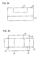
- FIG. 3A shows the structure of FIG. 2B following a wet etch procedure formed in accordance with embodiments of the present invention.
- FIG. 3B depicts a top view of the structure of FIG. 3A with a mask in place.
- FIG. 4A depicts the structure of 3 A following the formation of dielectric support structures in accordance with embodiments of the present invention.
- FIG. 4B shows the structure of FIG. 4A, with the mask in place.
- FIG. 5 shows the structure of FIG. 4A following further processing steps to form a MOSFET, in accordance with embodiments of the present invention.
- the present invention addresses problems related to the formation of SOI devices, and the capacitance between the source/drain regions and the substrate in SOI devices.
- the present invention improves upon the conventional devices by reducing the capacitance between the source/drain regions and the substrate. This is achieved, in part by the formation of a void underneath the silicon body of an SOI structure.
- the silicon body is supported by dielectric support structures, maintaining the void between the silicon body and the substrate. Since the air in the void has a much lower dielectric constant than the typical oxide employed in the insulator layer of an SOI structure, the capacitance between the source/drain regions and the substrate is significantly reduced.
- FIG. 1A depicts the cross-section of a silicon-on-insulator (SOI) precursor constructed in accordance with embodiments of the present invention.
- a precursor 10 may be formed in a conventional manner and includes a silicon substrate 12 , formed of bulk silicon.
- An insulator layer 14 or buried oxide layer, is provided on the substrate 12 .
- a silicon body 16 is provided on the buried oxide (BOX) layer 14 .
- This silicon body 16 forms an island, or a silicon island, as it is surrounded on its periphery by isolation regions 18 .
- These isolation regions 18 may be formed of oxide, for example.
- a shallow trench isolation (STI) technique may be employed to form the isolation regions 18 .
- STI shallow trench isolation
- FIG. 1 B A top view of the SOI precursor 10 is provided in FIG. 1 B.
- FIG. 2A shows the SOI precursor 2 A as it is exposed by a mask 20 , depicted in FIG. 2 B.
- the mask 20 is a wet etch mask.
- the isolation regions 18 that are not covered by the mask 20 will not be etched during the wet etching procedure.
- the wet etch mask 20 exposes portions 19 of the isolation regions 18 to the etchant.
- the silicon body 16 is also exposed to the etchant.
- a suitable etchant is employed that is highly selective to etch the oxide in the portions 19 of the isolation regions 18 that are exposed by the mask 20 , and not etch the silicon body 16 .
- a suitable exemplary etch is a buffered oxide etch (BOE) well known to those of ordinary skill in the art for preferentially etching oxide and maintaining the silicon intact.
- BOE buffered oxide etch
- the results of the wet etch step are depicted in FIG. 3 A and in FIG. 3 B.
- the isolation regions 18 exposed by the mask 20 are etched through to create a void 22 that also extend underneath the silicon body 16 .
- the silicon body 16 is suspended by the isolation regions 18 that have not been etched. This can best be seen in FIG. 3 B. At this point in the formation process, only two sides of the periphery of the silicon body 16 are contacted by the isolation regions 18 , rather than all four sides.
- dielectric support structures 24 are formed, as depicted in FIG. 4 A.
- the dielectric support structures 24 are formed by deposition of a dielectric material, such as silicon dioxide, into the isolation regions 18 that were etched through.
- a conventional deposition technique such as chemical vapor deposition, may be employed to deposit the dielectric support structures 24 .
- the dielectric support structures 24 together with the isolation regions 18 that were not etched, securely support the silicon body 16 above the substrate 12 , with a void 26 formed between the silicon body 16 and the substrate 12 .
- the void 26 will contain air, which has a dielectric constant of one. This dielectric constant is much lower than that of the buried oxide material that was previously underneath the silicon body 16 . This reduces the capacitance between the source/drain regions that will be formed in the silicon body 16 and the substrate 12 . Improved performance of the SOI device is therefore a result.
- a top view of the SO structure and mask 20 is provided in FIG. 4 B.
- Source/drain regions 28 are formed in the silicon body 16 .
- a gate electrode 30 is provided on the silicon body 16 , over a gate dielectric.
- Dielectric material 32 is formed over the gate electrode 30 .
- Silicide regions 38 are provided on the source/drain regions 28 and the gate electrode 30 .
- Sidewalls 34 are formed on the sides of the gate electrode 30 .
- Contacts 36 may be formed through the dielectric layer 32 to the silicide regions 38 .
- the completed SOI device depicted in FIG. 5 exhibits reduced capacitance between the source/drain regions 28 and the substrate 12 , due to the lower dielectric constant in the void 26 underneath the silicon body 16 , as compared to conventional SOI structures in which the silicon body is on an oxide layer.
Abstract
An SOI semiconductor and method for making the same includes a substrate and dielectric support structures that support a silicon body above the substrate. This creates a void underneath the silicon body and thereby reduces the capacitance between the source/drain regions on body and the substrate.
Description
The present invention relates to the field of semiconductor manufacturing, and more particularly, to the formation of a silicon-on-insulator structure with improved capacitance characteristics.
Silicon-on-insulator (SOI) metal-oxide semiconductor field effect transistors (MOSFETs) are well known in the field of semiconductors. SOI MOSFETs have been demonstrated to be superior to bulk silicon MOSFETs in low-power, high-speed, very large scale integration (VLSI) applications. Some of the advantages include (1) less junction capacitance so that higher circuit speed can be achieved; (2) better device isolation; and (3) sufficient radiation hardness.
A conventional SOI structure comprises a substrate made of silicon, for example. An insulator layer is formed over the substrate, and is typically an oxide, such as silicon oxide. A silicon body, or silicon island, is formed on the insulator layer. This causes the insulator layer to be a “buried oxide” layer or BOX layer. The silicon bodies are isolated from one another by shallow trench isolation (STI) regions or other isolation regions. The source/drain regions are formed in the silicon body and the gate electrode is formed on top of the silicon body, thus forming the MOSFET device.
One of the limiting factors in transistor performance in SOI devices is the capacitance that exists from the source/drain regions to the substrate. The typical dielectric constant of the oxide that is conventionally used as the insulator layer of SOI devices is approximately 3.9. Reduction in the capacitance from the source/drain regions to the substrate will improve overall performance of the device by lowering the RC time constant.
There is a need for a SOI device that exhibits reduced capacitance between the source/drain regions and the substrate.
These and other needs are met by embodiments of the present invention which provide a semiconductor device comprising a substrate, dielectric support structures, and a silicon body held between the dielectric support structures and above the substrate such that a void is formed between the silicon body and the substrate.
The void between the silicon body and the substrate, as provided by the present invention, has the advantage of presenting a reduced dielectric constant and thereby reduction in the capacitance between source/drain regions and the substrate. For example, the dielectric constant of air is equal to one, which is significantly lower than the dielectric constant for silicon dioxide (approximately 3.9). The reduced capacitance improves the overall performance of the device of the present invention.
The earlier stated needs are also met by embodiments of the present invention which provide a method of forming a semiconductor device comprising the steps of forming a silicon-on-insulator precursor including a substrate, a buried oxide layer on the substrate, a silicon body on the buried oxide layer, and isolation regions surrounding the periphery of the silicon body. The portions of the buried oxide layer that are under the silicon body are etched to create a void between the substrate and the silicon body.
The etching of portions of the buried oxide layer in accordance with the embodiments of the present invention serves to create the void that provides the reduced dielectric constant between the source/drain regions and the substrate. The etching allows the creation of the void in a production-worthy method.
The earlier stated needs are also met by embodiments of the present invention which provide a method of forming a semiconductor device comprising the steps of forming a SOI structure having a substrate, an insulator on the substrate, a silicon body on the insulator, and isolation regions surrounding the periphery of the silicon body. In this method, a void is formed in the insulator layer between the silicon body and the substrate.
The foregoing and other features, aspects and advantages of the present invention will become more apparent from the following detailed description when taken in conjunction with the accompanying drawings.
FIG. 1A is a cross-section of a silicon-on-insulator (SOI) precursor formed in accordance with embodiments of the present invention.
FIG. 1B is a top view of the SOI precursor of FIG. 1A.
FIG. 2A depicts the structure of FIG. 1A following the formation of an etch mask in accordance with embodiments of the present invention.
FIG. 2B depicts the top view of the structure of FIG. 2A after the wet etch mask has been formed.
FIG. 3A shows the structure of FIG. 2B following a wet etch procedure formed in accordance with embodiments of the present invention.
FIG. 3B depicts a top view of the structure of FIG. 3A with a mask in place.
FIG. 4A depicts the structure of 3A following the formation of dielectric support structures in accordance with embodiments of the present invention.
FIG. 4B shows the structure of FIG. 4A, with the mask in place.
FIG. 5 shows the structure of FIG. 4A following further processing steps to form a MOSFET, in accordance with embodiments of the present invention.
The present invention addresses problems related to the formation of SOI devices, and the capacitance between the source/drain regions and the substrate in SOI devices. The present invention improves upon the conventional devices by reducing the capacitance between the source/drain regions and the substrate. This is achieved, in part by the formation of a void underneath the silicon body of an SOI structure. The silicon body is supported by dielectric support structures, maintaining the void between the silicon body and the substrate. Since the air in the void has a much lower dielectric constant than the typical oxide employed in the insulator layer of an SOI structure, the capacitance between the source/drain regions and the substrate is significantly reduced.
FIG. 1A depicts the cross-section of a silicon-on-insulator (SOI) precursor constructed in accordance with embodiments of the present invention. A precursor 10 may be formed in a conventional manner and includes a silicon substrate 12, formed of bulk silicon. An insulator layer 14, or buried oxide layer, is provided on the substrate 12. A silicon body 16 is provided on the buried oxide (BOX) layer 14. This silicon body 16 forms an island, or a silicon island, as it is surrounded on its periphery by isolation regions 18. These isolation regions 18 may be formed of oxide, for example. A shallow trench isolation (STI) technique may be employed to form the isolation regions 18.
Conventional methodologies may be employed to create the precursor 10, such as SIMOX and others. A top view of the SOI precursor 10 is provided in FIG. 1B.
FIG. 2A shows the SOI precursor 2A as it is exposed by a mask 20, depicted in FIG. 2B. The mask 20 is a wet etch mask.
The isolation regions 18 that are not covered by the mask 20 will not be etched during the wet etching procedure. The wet etch mask 20 exposes portions 19 of the isolation regions 18 to the etchant. The silicon body 16 is also exposed to the etchant. A suitable etchant is employed that is highly selective to etch the oxide in the portions 19 of the isolation regions 18 that are exposed by the mask 20, and not etch the silicon body 16. A suitable exemplary etch is a buffered oxide etch (BOE) well known to those of ordinary skill in the art for preferentially etching oxide and maintaining the silicon intact.
The results of the wet etch step are depicted in FIG. 3A and in FIG. 3B. The isolation regions 18 exposed by the mask 20 are etched through to create a void 22 that also extend underneath the silicon body 16.
The silicon body 16 is suspended by the isolation regions 18 that have not been etched. This can best be seen in FIG. 3B. At this point in the formation process, only two sides of the periphery of the silicon body 16 are contacted by the isolation regions 18, rather than all four sides.
In order to provide enhanced structural stability, dielectric support structures 24 are formed, as depicted in FIG. 4A. The dielectric support structures 24 are formed by deposition of a dielectric material, such as silicon dioxide, into the isolation regions 18 that were etched through. A conventional deposition technique, such as chemical vapor deposition, may be employed to deposit the dielectric support structures 24.
The dielectric support structures 24, together with the isolation regions 18 that were not etched, securely support the silicon body 16 above the substrate 12, with a void 26 formed between the silicon body 16 and the substrate 12. The void 26 will contain air, which has a dielectric constant of one. This dielectric constant is much lower than that of the buried oxide material that was previously underneath the silicon body 16. This reduces the capacitance between the source/drain regions that will be formed in the silicon body 16 and the substrate 12. Improved performance of the SOI device is therefore a result. A top view of the SO structure and mask 20 is provided in FIG. 4B.
Following the formation of the dielectric support structures 24 and the void 26 underneath the silicon body 16, further processing may be performed in a conventional manner to complete the formation of an SOI device. An exemplary embodiment of an SOI device constructed in accordance with the present invention is provided in FIG. 5. Source/drain regions 28 are formed in the silicon body 16. A gate electrode 30 is provided on the silicon body 16, over a gate dielectric. Dielectric material 32 is formed over the gate electrode 30. Silicide regions 38 are provided on the source/drain regions 28 and the gate electrode 30. Sidewalls 34 are formed on the sides of the gate electrode 30. Contacts 36 may be formed through the dielectric layer 32 to the silicide regions 38.
The completed SOI device depicted in FIG. 5 exhibits reduced capacitance between the source/drain regions 28 and the substrate 12, due to the lower dielectric constant in the void 26 underneath the silicon body 16, as compared to conventional SOI structures in which the silicon body is on an oxide layer.
Although the present invention has been described and illustrated in detail, it is to be clearly understood that the same is by way of illustration and example only, and is not to be taken by way of limitation, the scope of the present invention be limited only by the terms of the appended claims.
Claims (12)
1. A method of forming a semiconductor device, comprising the steps of:
forming a silicon-on-insulator (SOI) precursor including a substrate, a buried oxide layer on the substrate, a silicon body on the buried oxide layer; and isolation regions surrounding the periphery of the silicon body;
etching portions of the buried oxide layer under the silicon body to create a void between the substrate and the silicon body; and
forming active regions in the silicon body and a gate electrode on the silicon body to form an operative semiconductor device having the void between the substrate and the silicon body.
2. The method of claim 1 , further comprising forming dielectric support structures on the periphery of the silicon body.
3. The method of claim 2 , wherein the step of etching portions of the buried oxide layer include etching through at least some of the isolation regions.
4. The method of claim 3 , wherein the dielectric support structures are formed in place of the isolation regions that have been etched through.
5. The method of claim 4 , wherein the dielectric support structures comprise SiO2.
6. The method of claim 4 , wherein the step of etching portions of the buried oxide layer includes performing a wet etch.
7. The method of claim 6 , wherein the wet etch is a buffered oxide etch.
8. A method of forming a semiconductor device, comprising the steps of: forming an silicon-on-insulator (SOI) structure having a substrate, an insulator layer
on the substrate, a silicon body on the insulator layer, and isolation regions surrounding the periphery of the silicon body;
forming a void in the insulator layer between the silicon body and the substrate; and
forming active regions in the silicon body and a gate electrode on the silicon body to form an operative semiconductor device having the void between the substrate and the silicon body.
9. The method of claim 8 , wherein the step of forming a void includes etching the SOI structure with a wet etch to etch through portions of the isolation regions and etch the insulator layer between the silicon body and the substrate.
10. The method of claim 9 , wherein the step of etching includes forming a mask over the SOI structure, the mask protecting at least some of the isolation regions from etching.
11. The method of claim 10 , wherein the wet etch comprises a buffered oxide etch.
12. The method of claim 10 , further comprising depositing a dielectric material on the SOI structure to replace the portions of the isolation regions that have been etched through the dielectric material forming support structures for the silicon body and extending to the substrate.
Priority Applications (1)
| Application Number | Priority Date | Filing Date | Title |
|---|---|---|---|
| US10/460,160 US6830987B1 (en) | 2003-06-13 | 2003-06-13 | Semiconductor device with a silicon-on-void structure and method of making the same |
Applications Claiming Priority (1)
| Application Number | Priority Date | Filing Date | Title |
|---|---|---|---|
| US10/460,160 US6830987B1 (en) | 2003-06-13 | 2003-06-13 | Semiconductor device with a silicon-on-void structure and method of making the same |
Publications (1)
| Publication Number | Publication Date |
|---|---|
| US6830987B1 true US6830987B1 (en) | 2004-12-14 |
Family
ID=33490470
Family Applications (1)
| Application Number | Title | Priority Date | Filing Date |
|---|---|---|---|
| US10/460,160 Expired - Lifetime US6830987B1 (en) | 2003-06-13 | 2003-06-13 | Semiconductor device with a silicon-on-void structure and method of making the same |
Country Status (1)
| Country | Link |
|---|---|
| US (1) | US6830987B1 (en) |
Cited By (5)
| Publication number | Priority date | Publication date | Assignee | Title |
|---|---|---|---|---|
| US20040129998A1 (en) * | 2002-09-19 | 2004-07-08 | Kazumi Inoh | Semiconductor device with a cavity therein and a method of manufacturing the same |
| US20050215037A1 (en) * | 2004-03-26 | 2005-09-29 | Texas Instruments, Incorporated | Method for manufacturing a semiconductor device having a silicided gate electrode and a method for manufacturing an integrated circuit including the same |
| US20060189157A1 (en) * | 2005-01-21 | 2006-08-24 | Stmicroelectronics S.A. | Method for forming an integrated circuit semiconductor substrate |
| US8610211B2 (en) | 2010-07-23 | 2013-12-17 | International Business Machines Corporation | Semiconductor-on-insulator (SOI) structure with selectively placed sub-insulator layer void(s) and method of forming the SOI structure |
| JP2013258258A (en) * | 2012-06-12 | 2013-12-26 | Takehide Shirato | Semiconductor device and manufacturing method of the same |
Citations (11)
| Publication number | Priority date | Publication date | Assignee | Title |
|---|---|---|---|---|
| US5689087A (en) * | 1994-10-04 | 1997-11-18 | Santa Barbara Research Center | Integrated thermopile sensor for automotive, spectroscopic and imaging applications, and methods of fabricating same |
| US5811315A (en) * | 1997-03-13 | 1998-09-22 | National Semiconductor Corporation | Method of forming and planarizing deep isolation trenches in a silicon-on-insulator (SOI) structure |
| US6200866B1 (en) * | 1998-02-23 | 2001-03-13 | Sharp Laboratories Of America, Inc. | Use of silicon germanium and other alloys as the replacement gate for the fabrication of MOSFET |
| US20020017689A1 (en) * | 2000-08-04 | 2002-02-14 | Mitsubishi Denki Kabushiki Kaisha | Semiconductor device and method of manufacturing same |
| US6396113B1 (en) * | 1999-11-19 | 2002-05-28 | Mitsubishi Denki Kabushiki Kaisha | Active trench isolation structure to prevent punch-through and junction leakage |
| US20020115268A1 (en) * | 2001-02-19 | 2002-08-22 | Samsung Electronics Co., Ltd. | Silicon-on-insulator (SOI) substrate and method for manufacturing the same |
| US20030062332A1 (en) * | 2001-09-28 | 2003-04-03 | Harris Richard D. | Method for fabricating a microelectromechanical system (MEMS) device using a pre-patterned bridge |
| US6548364B2 (en) * | 2001-03-29 | 2003-04-15 | Sharp Laboratories Of America, Inc. | Self-aligned SiGe HBT BiCMOS on SOI substrate and method of fabricating the same |
| US6563173B2 (en) * | 1998-01-20 | 2003-05-13 | International Business Machines Corporation | Silicon-on-insulator chip having an isolation barrier for reliability |
| US6744113B2 (en) * | 2002-09-13 | 2004-06-01 | Renesas Technology Corp. | Semiconductor device with element isolation using impurity-doped insulator and oxynitride film |
| US20040126985A1 (en) * | 2002-12-30 | 2004-07-01 | Bendernagel Robert E. | Formation of patterned silicon-on-insulator (SOI)/silicon-on-nothing (SON) composite structure by porous Si engineering |
-
2003
- 2003-06-13 US US10/460,160 patent/US6830987B1/en not_active Expired - Lifetime
Patent Citations (11)
| Publication number | Priority date | Publication date | Assignee | Title |
|---|---|---|---|---|
| US5689087A (en) * | 1994-10-04 | 1997-11-18 | Santa Barbara Research Center | Integrated thermopile sensor for automotive, spectroscopic and imaging applications, and methods of fabricating same |
| US5811315A (en) * | 1997-03-13 | 1998-09-22 | National Semiconductor Corporation | Method of forming and planarizing deep isolation trenches in a silicon-on-insulator (SOI) structure |
| US6563173B2 (en) * | 1998-01-20 | 2003-05-13 | International Business Machines Corporation | Silicon-on-insulator chip having an isolation barrier for reliability |
| US6200866B1 (en) * | 1998-02-23 | 2001-03-13 | Sharp Laboratories Of America, Inc. | Use of silicon germanium and other alloys as the replacement gate for the fabrication of MOSFET |
| US6396113B1 (en) * | 1999-11-19 | 2002-05-28 | Mitsubishi Denki Kabushiki Kaisha | Active trench isolation structure to prevent punch-through and junction leakage |
| US20020017689A1 (en) * | 2000-08-04 | 2002-02-14 | Mitsubishi Denki Kabushiki Kaisha | Semiconductor device and method of manufacturing same |
| US20020115268A1 (en) * | 2001-02-19 | 2002-08-22 | Samsung Electronics Co., Ltd. | Silicon-on-insulator (SOI) substrate and method for manufacturing the same |
| US6548364B2 (en) * | 2001-03-29 | 2003-04-15 | Sharp Laboratories Of America, Inc. | Self-aligned SiGe HBT BiCMOS on SOI substrate and method of fabricating the same |
| US20030062332A1 (en) * | 2001-09-28 | 2003-04-03 | Harris Richard D. | Method for fabricating a microelectromechanical system (MEMS) device using a pre-patterned bridge |
| US6744113B2 (en) * | 2002-09-13 | 2004-06-01 | Renesas Technology Corp. | Semiconductor device with element isolation using impurity-doped insulator and oxynitride film |
| US20040126985A1 (en) * | 2002-12-30 | 2004-07-01 | Bendernagel Robert E. | Formation of patterned silicon-on-insulator (SOI)/silicon-on-nothing (SON) composite structure by porous Si engineering |
Cited By (11)
| Publication number | Priority date | Publication date | Assignee | Title |
|---|---|---|---|---|
| US20040129998A1 (en) * | 2002-09-19 | 2004-07-08 | Kazumi Inoh | Semiconductor device with a cavity therein and a method of manufacturing the same |
| US7009273B2 (en) * | 2002-09-19 | 2006-03-07 | Kabushiki Kaisha Toshiba | Semiconductor device with a cavity therein and a method of manufacturing the same |
| US20060157789A1 (en) * | 2002-09-19 | 2006-07-20 | Kazumi Inoh | Semiconductor device with a cavity therein and a method of manufacturing the same |
| US7145215B2 (en) * | 2002-09-19 | 2006-12-05 | Kabushiki Kaisha Toshiba | Semiconductor device with a cavity therein and a method of manufacturing the same |
| US20050215037A1 (en) * | 2004-03-26 | 2005-09-29 | Texas Instruments, Incorporated | Method for manufacturing a semiconductor device having a silicided gate electrode and a method for manufacturing an integrated circuit including the same |
| US7338888B2 (en) * | 2004-03-26 | 2008-03-04 | Texas Instruments Incorporated | Method for manufacturing a semiconductor device having a silicided gate electrode and a method for manufacturing an integrated circuit including the same |
| US20060189157A1 (en) * | 2005-01-21 | 2006-08-24 | Stmicroelectronics S.A. | Method for forming an integrated circuit semiconductor substrate |
| US7476574B2 (en) * | 2005-01-21 | 2009-01-13 | Stmicroelectronics S.A. | Method for forming an integrated circuit semiconductor substrate |
| US8610211B2 (en) | 2010-07-23 | 2013-12-17 | International Business Machines Corporation | Semiconductor-on-insulator (SOI) structure with selectively placed sub-insulator layer void(s) and method of forming the SOI structure |
| US9059203B2 (en) | 2010-07-23 | 2015-06-16 | International Business Machines Corporation | Semiconductor-on-insulator (SOI) structure with selectivity placed sub-insulator layer void(s) and method of forming the SOI structure |
| JP2013258258A (en) * | 2012-06-12 | 2013-12-26 | Takehide Shirato | Semiconductor device and manufacturing method of the same |
Similar Documents
| Publication | Publication Date | Title |
|---|---|---|
| US6949420B1 (en) | Silicon-on-insulator (SOI) substrate having dual surface crystallographic orientations and method of forming same | |
| KR101208781B1 (en) | Isolated tri-gate transistor fabricated on bulk substrate | |
| CN100461430C (en) | Semiconductor structure and its forming method | |
| US7648871B2 (en) | Field effect transistors (FETS) with inverted source/drain metallic contacts, and method of fabricating same | |
| US20020175378A1 (en) | SOI substrate having an etch stop layer, and fabrication method thereof, SOI integrated circuit fabricated thereon, and method of fabricating SOI integrated circuit using the same | |
| US6787423B1 (en) | Strained-silicon semiconductor device | |
| JP2003512724A (en) | Field effect transistor with non-floating body and method for forming the transistor on a bulk silicon wafer | |
| JP2002033490A (en) | Manufacturing method for soi-mos field-effect transistor | |
| US6617202B2 (en) | Method for fabricating a full depletion type SOI device | |
| US5438015A (en) | Silicon-on-insulator technique with buried gap | |
| US6897122B1 (en) | Wide neck shallow trench isolation region to prevent strain relaxation at shallow trench isolation region edges | |
| US6830987B1 (en) | Semiconductor device with a silicon-on-void structure and method of making the same | |
| US6352903B1 (en) | Junction isolation | |
| CN112382605A (en) | Method for manufacturing FDSOI | |
| US8497556B2 (en) | Semiconductor devices with active semiconductor height variation | |
| US7288447B2 (en) | Semiconductor device having trench isolation for differential stress and method therefor | |
| US20210305088A1 (en) | Method for manufacturing semiconductor structure | |
| US20020167049A1 (en) | Field-effect transistor and manufacture thereof | |
| KR100539008B1 (en) | METHOD FOR MAKING Fin TRANSISTOR | |
| KR960042931A (en) | Manufacturing Method of Semiconductor Device Having SOI Structure | |
| US6664165B2 (en) | Semiconductor device and fabrication method therefor | |
| US10796943B2 (en) | Manufacturing method of semiconductor structure | |
| TW513755B (en) | Manufacture method of semiconductor device with self-aligned inter-well isolation | |
| KR100412144B1 (en) | Method for manufacturing semiconductor device | |
| KR19980029390A (en) | Manufacturing method of semiconductor device |
Legal Events
| Date | Code | Title | Description |
|---|---|---|---|
| AS | Assignment |
Owner name: ADVANCED MICRO DEVICES, INC., CALIFORNIA Free format text: ASSIGNMENT OF ASSIGNORS INTEREST;ASSIGNORS:PELELLA, MARIO M.;KRISHNAN, SRINATH;EN, WILLIAM G.;AND OTHERS;REEL/FRAME:014177/0962;SIGNING DATES FROM 20030317 TO 20030508 |
|
| STCF | Information on status: patent grant |
Free format text: PATENTED CASE |
|
| FPAY | Fee payment |
Year of fee payment: 4 |
|
| FPAY | Fee payment |
Year of fee payment: 8 |
|
| FPAY | Fee payment |
Year of fee payment: 12 |