US6803771B2 - Paving material analyzer system and method - Google Patents

Paving material analyzer system and method Download PDF

Info

Publication number
US6803771B2
US6803771B2 US10/185,510 US18551002A US6803771B2 US 6803771 B2 US6803771 B2 US 6803771B2 US 18551002 A US18551002 A US 18551002A US 6803771 B2 US6803771 B2 US 6803771B2
Authority
US
United States
Prior art keywords
paving material
impedance
sensor
determining
density
Prior art date
Legal status (The legal status is an assumption and is not a legal conclusion. Google has not performed a legal analysis and makes no representation as to the accuracy of the status listed.)
Expired - Lifetime, expires
Application number
US10/185,510
Other versions
US20020175691A1 (en
Inventor
Robert A. Sovik
Richard N. Hosterman
George G. Moross
Current Assignee (The listed assignees may be inaccurate. Google has not performed a legal analysis and makes no representation or warranty as to the accuracy of the list.)
TransTech Systems Inc
Original Assignee
TransTech Systems Inc
Priority date (The priority date is an assumption and is not a legal conclusion. Google has not performed a legal analysis and makes no representation as to the accuracy of the date listed.)
Filing date
Publication date
Family has litigation
First worldwide family litigation filed litigation Critical https://patents.darts-ip.com/?family=46279281&utm_source=google_patent&utm_medium=platform_link&utm_campaign=public_patent_search&patent=US6803771(B2) "Global patent litigation dataset” by Darts-ip is licensed under a Creative Commons Attribution 4.0 International License.
US case filed in North Carolina Eastern District Court litigation https://portal.unifiedpatents.com/litigation/North%20Carolina%20Eastern%20District%20Court/case/5%3A21-cv-00265 Source: District Court Jurisdiction: North Carolina Eastern District Court "Unified Patents Litigation Data" by Unified Patents is licensed under a Creative Commons Attribution 4.0 International License.
Priority claimed from US09/565,022 external-priority patent/US6414497B1/en
Application filed by TransTech Systems Inc filed Critical TransTech Systems Inc
Priority to US10/185,510 priority Critical patent/US6803771B2/en
Assigned to TRANSTECH SYSTEMS, INC. reassignment TRANSTECH SYSTEMS, INC. ASSIGNMENT OF ASSIGNORS INTEREST (SEE DOCUMENT FOR DETAILS). Assignors: HOSTERMAN, RICHARD N., MOROSS, GEORGE G., SOVIK, ROBERT A.
Publication of US20020175691A1 publication Critical patent/US20020175691A1/en
Application granted granted Critical
Publication of US6803771B2 publication Critical patent/US6803771B2/en
Adjusted expiration legal-status Critical
Expired - Lifetime legal-status Critical Current

Links

Images

Classifications

    • GPHYSICS
    • G01MEASURING; TESTING
    • G01NINVESTIGATING OR ANALYSING MATERIALS BY DETERMINING THEIR CHEMICAL OR PHYSICAL PROPERTIES
    • G01N9/00Investigating density or specific gravity of materials; Analysing materials by determining density or specific gravity
    • GPHYSICS
    • G01MEASURING; TESTING
    • G01NINVESTIGATING OR ANALYSING MATERIALS BY DETERMINING THEIR CHEMICAL OR PHYSICAL PROPERTIES
    • G01N27/00Investigating or analysing materials by the use of electric, electrochemical, or magnetic means
    • G01N27/02Investigating or analysing materials by the use of electric, electrochemical, or magnetic means by investigating impedance
    • GPHYSICS
    • G01MEASURING; TESTING
    • G01NINVESTIGATING OR ANALYSING MATERIALS BY DETERMINING THEIR CHEMICAL OR PHYSICAL PROPERTIES
    • G01N33/00Investigating or analysing materials by specific methods not covered by groups G01N1/00 - G01N31/00
    • G01N33/42Road-making materials

Definitions

  • the present invention relates generally to paving material density analyzers. More particularly, the present invention relates to a paving material analyzer system and a method for analyzing paving material. The invention also relates to mechanisms for improving the accuracy of a paving material analyzer system and method.
  • paving material is usually laid at about 75% of acceptable compaction.
  • Acceptable compaction is a recommended level of compaction that reduces variations in the material, such as air voids, that can create potential defects in the paving material. It is highly advantageous to compact the paving material to a level as close to acceptable compaction as possible. Unfortunately, the level of compaction is not readily apparent by viewing the compacted paving material. In order to address this problem, measurement of dielectric properties of paving material is known to be very useful for determining material density, a key indicator of compaction level.
  • Blackwell U.S. Pat. No. 3,784,905.
  • Blackwell's device measures dielectric properties of the asphalt, which is representative of the change in density in the asphalt.
  • the device of Blackwell has many disadvantages. For example, in order to obtain a reading, the Blackwell device must be moved at extremely slow speeds across the material being tested and, accordingly, requires an extended time period to provide a determination. The Blackwell device, due to its excessive weight, also requires a large sled frame (contact area) to be dragged across the pavement surface. Another disadvantage is limited adjustability of the depth of measurement of the device caused by the given set of electrodes only being able to vary the depth of measurement by changing the height of the electrodes. Yet another disadvantage is the inability to measure density when the paving material is wet.
  • a nuclear source is used to determine density of pavement material.
  • This device has a variety of obvious drawbacks. For instance, the device requires a licensed operator and a radiation shield (e.g., a lead enclosure). Furthermore, the device is non-adjustable for area, time-consuming in use, and heavy.
  • Another disadvantage of the above-described devices is their inability to vary the shape and area of the sensing area. Altering the shape and area of the sensing area is advantageous for determining the density in particular pavement attributes, e.g., dips, joints, odd shaped patches, etc.
  • Another shortcoming of current devices is inaccuracy created by, among other things, moisture on a surface of the paving material and a standoff distance of the sensor from the paving material surface.
  • a paving material analyzer system comprising: a sensor; an electronic circuit operatively coupled to the sensor to generate an electrical field from the sensor proximate the paving material; and a data analyzer that determines a density of the paving material based on the effect of impedance characteristics of the paving material on the electrical field.
  • a second aspect of the invention provides a method for analyzing paving material comprising the steps of: determining an impedance of the paving material; and determining the density of the paving material based on the impedance determination of the paving material.
  • a third aspect of the invention provides a paving material analyzer system comprising: means for determining an impedance of the paving material; and means for determining the density of the paving material based on the impedance determination of the paving material.
  • a paving material analyzer system comprising: a sensor; an electronic circuit operatively coupled to the sensor to generate an electrical field from the sensor proximate the paving material; and a density determining data analyzer that determines a density of the paving material regardless of moisture presence on the paving material.
  • a fifth aspect of the invention is directed to a paving material analyzer system comprising: an electronic circuit including an inductor adapted to null a capacitive reactance portion of an impedance reading of the paving material leaving a non-reactive portion; and a data analyzer operatively coupled to the electronic circuit that determines: a total impedance of the paving material based on the non-reactive portion, a known inductive reactance and a known operating frequency of the electronic circuit, and a density of the paving material based on the total impedance.
  • a sixth aspect of the invention is directed to a paving material analyzer system comprising: means for measuring an impedance of the paving material and nulling a capacitive reactance portion of the impedance; means for analyzing data operatively coupled to the means for measuring, the means for analyzing determining: a total impedance of the paving material based on a non-reactive portion of the impedance, a known inductive reactance portion of the impedance and a known operational frequency of the means for measuring, and a density of the paving material based on the total impedance.
  • a seventh aspect of the invention provides a method for analyzing paving material comprising the steps of: determining an impedance of the paving material; determining a capacitance of a space between a sensor and the paving material; and determining the density of the paving material based on the impedance determination of the paving material and the capacitance of the space.
  • An eighth aspect of the invention is directed to a paving material analyzer system having a sensor operatively couple to an electronic circuit for generating an electric field proximate paving material and a data analyzer for determining a density of the paving material, the system comprising: a standoff distance corrector that corrects the density for a distance of the sensor to the paving material.
  • FIG. 1 shows a schematic view of a paving material analyzer system
  • FIG. 2 shows a cross-sectional view of the system of FIG. 1 in use
  • FIG. 3 shows a circuit diagram of a sensor circuit
  • FIG. 4 shows a cross-sectional view of an alternative operational setting of the system of FIG. 1;
  • FIG. 5 shows a detail view of a first alternative embodiment of a sensor
  • FIG. 6 shows a detail view of a second alternative embodiment of a sensor
  • FIG. 7 shows a detail view of a third alternative embodiment of a sensor
  • FIG. 8 shows a paving material profile
  • FIG. 9 shows a circuit diagram of an alternative sensor circuit
  • FIG. 10 shows a circuit diagram of another alternative sensor circuit
  • FIG. 11 shows a circuit diagram of another alternative sensor circuit.
  • paving material should be interpreted broadly to include all varieties of asphalt, cement, concrete, soil, sand, stones, bituminous material and all other forms of in-place material.
  • System 10 includes a sensor 20 and an analyzer unit 22 .
  • Analyzer unit 22 preferably has a sensor circuit 24 and a data analyzer 28 .
  • Sensor circuit 24 is an electronic circuit that: 1) applies an electric potential to sensor 20 to generate, or transmit, an electrical field; and 2) receives the electrical field.
  • Sensor circuit 24 preferably includes a guarded circuit 26 .
  • data analyzer 28 may include a percentage compaction calculator 27 , a display 29 and a correction system 30 .
  • Sensor 20 may include an active inner element 32 surrounded by an intermediate ground element 34 which is surrounded by a first outer element 36 and a second outer element 38 .
  • an electrical field 40 is created proximate paving material 42 by applying an electric potential (from electronic circuit 24 shown in FIG. 1) through sensor 20 .
  • Electrical field 40 is transmitted from sensor 20 via element 38 and/or element 36 into adjacent paving material 42 .
  • Sensor 20 may be in contact with paving material 42 during use.
  • Inner element 32 then receives this electrical field signal from paving material 42 , the signal having been altered by the impedance characteristics of paving material 42 .
  • Each of elements 32 , 34 , 36 , 38 may be constructed of any conducting material, but are preferably made of copper, aluminum or steel. Elements are held together and insulated from each other by a non-conductive material such as an epoxy.
  • sensor circuit 24 preferably includes a transmitting circuit 44 and a receiving circuit 45 . While preferred embodiments of these circuits have been illustrated, it should be noted that these circuits 24 , 44 , 45 may take a variety of forms. The embodiments disclosed for each should, therefore, not be taken as limiting the invention to any particular number or form of circuitry.
  • transmitting circuit 44 is a constant voltage source circuit.
  • Circuit 44 includes a square wave oscillator (crystal) 46 coupled to a high speed switch 48 .
  • a reference voltage 50 is supplied to an error amplifier 52 that is also coupled to high speed switch 48 .
  • An amplitude detector 54 is also coupled to error amplifier 52 .
  • a low pass filter 56 is provided at an output of high speed switch 48 . Output of low pass filter 56 is the constant voltage sine wave output for sensor 20 .
  • Amplitude detector 54 also receives the output of low pass filter 56 and maintains the constant voltage output.
  • the output to sensor 20 preferably has a frequency in the range of 200 kHz to 15 MHz. It should be recognized that while a preferred constant voltage source circuit has been illustrated, other systems that provide a constant voltage source are also possible. Accordingly, the invention should not be limited to any particular form of constant voltage source circuitry.
  • a phase detector 47 and an amplitude detector 49 receive the electrical field signal back from sensor 20 .
  • Phase detector 47 is also coupled to an amplitude detector 54 , which it may share with transmitting circuit 44 .
  • Phase detector 47 and amplitude detector 49 feed to a low pass filter 51 and a low pass filter 53 , respectively.
  • the outputs of low pass filters 51 , 53 are coupled to data analyzer 28 for analysis of the electrical field signal.
  • guarded circuit 26 is included so sensor circuit 24 and sensor 20 are guarded. In this setting, guarded circuit 26 would be coupled to an additional element 74 , shown in FIG. 5 . Element 74 acts as a guard element for sensor 20 . It has been found that this promotes accuracy because determinations are not subject to stray fields.
  • system 10 includes a data analyzer 28 .
  • data analyzer 28 is a microcomputer configured to determine the density of paving material 42 based on the effect of the impedance characteristics of paving material 42 on electrical field 40 .
  • data analyzer 28 determines an impedance value of paving material 42 , e.g., by comparing a transmitted electrical field signal versus a received electrical field signal that has passed through paving material 42 .
  • Data analyzer 28 uses the impedance value to determine a density value of paving material 42 . Impedance has been found to be a more useful measure of density than predecessor systems'use of capacitance.
  • Data analyzer 28 is capable of determining paving material density in terms of: 1) variations in paving material density across a measurement area, and 2) actual density indications. In order to determine the density of paving material 42 in terms of variations in density, variations in impedance of electrical field 40 created by the impedance characteristics of paving material 42 are tracked.
  • data analyzer 28 is configured to mathematically provide actual density determinations, e.g., 140 lb/ft 3 , and output them to a display 29 .
  • Density mathematical algorithms used to determine actual density indications may be created by modeling empirical data. Empirical data may be produced, for example, by calibrating a given sensor at a preferred operational setting with regard to specific types of paving material at known compaction densities. Mathematical modeling of the relationships between the measured impedance and known compaction densities results in a way to accurately determine density from an impedance of a specific type of paving material. Different mathematical algorithms can be created for different paving material and/or different sensors to make system 10 more accommodating, as will be described in more detail below. As one with skill in the art will appreciate, there may be other mechanisms other than mathematical modeling to determine actual density values. For instance, it may be possible to simply use the empirical data as a database to determine density, i.e., use the data as a lookup table.
  • Data analyzer 28 may also include a percentage compaction calculator 27 that calculates a percentage of maximum compaction, or percentage of air voids, of a particular paving material from the determination of density. The percentage can then be outputted to display 29 .
  • the relationship of density to a compaction percentage may be determined in many ways. One example method is by dividing the density determination by a known maximum compaction density for a particular paving material 42 that has been inputted to data analyzer 28 .
  • Data analyzer 28 may also be configured to calculate a compaction percentage without a separate calculator 27 , i.e., as part of its operations discussed above.
  • data analyzer 28 may also include a correction system 30 .
  • Correction system 30 may include a number of correction subsystems 58 , 64 , 66 , etc. for making corrections to an impedance determination and, hence, determination of density and percentage compaction.
  • a first preferred correction subsystem 58 is a moisture corrector that corrects for moisture 60 on a top surface 62 of paving material 42 , as shown in FIG. 2 .
  • moisture correction mathematical algorithms can be created by modeling empirical data of moisture content.
  • a moisture content mathematical algorithm can then be appropriately factored into the density mathematical algorithm to correct for moisture content, i.e., by removing a moisture content factor from the density mathematical algorithm. As a result, more accurate density determinations are possible.
  • a number of moisture content mathematical algorithms can be created for different paving material and/or different sensors to make system 10 more accommodating.
  • a system 10 can determine the density of paving material based on the effect on the electrical field caused by the impedance characteristics of the paving material and regardless of moisture presence on the paving material.
  • Any impedance determination completed by system 10 automatically includes a quantity that is attributable,solely to sensor 20 , i.e., a sensor impedance. Accordingly, inaccuracies may result unless the sensor impedance is removed from the overall impedance determination.
  • Sensor impedance may be created by a number of factors such as the type of a protective coating (not shown) that may be applied to sensor 20 and/or any air void that may be provided between a protective coating and sensor elements 32 , 34 , etc. Where a given system 10 will be used on only one paving material 42 and will not have a changeable sensor 20 , a pre-set sensor impedance correction factor can be used to remove the pre-determined sensor impedance from the density mathematical algorithms.
  • a sensor impedance corrector 64 is preferably provided as a second correction subsystem to remedy the problem.
  • a sensor impedance correction factor for each sensor may be predetermined, and a sensor selector 65 (FIG. 1) may be provided for choosing a given sensor and correction factor. Data analyzer 28 could then automatically correct for sensor impedance regardless of the sensor used.
  • a sensor selector 65 (FIG. 1) may be provided for choosing a given sensor and correction factor.
  • Data analyzer 28 could then automatically correct for sensor impedance regardless of the sensor used.
  • each sensor 20 may have a sensor impedance correction factor indicated thereon for input by a user into system 10 .
  • sensor impedance corrector 64 may also operate to implement different density mathematical algorithms for each sensor that automatically account for sensor impedance.
  • Another correction subsystem 66 that may be provided is for selection of a particular paving material 42 .
  • subsystem 66 could provide a paving material selector 67 (FIG. 1) so data analyzer 28 can automatically correct problems that may cause inaccuracies.
  • each common paving material would have a predetermined correction factor(s) associated therewith.
  • paving material selector 67 may operate to implement different density mathematical algorithms for each paving material that automatically account for any necessary special treatment.
  • a temperature corrector 68 may also be provided as a correction subsystem. Temperature corrector 68 would include a thermometer 70 and would create a correction factor by way of a correction algorithm. For instance, it has been found that an increase in paving material temperature results in a higher density determination and that the density determination can be corrected by subtracting a density value proportional to paving material temperature.
  • a standoff distance corrector 78 Another correction subsystem that may be provided is a standoff distance corrector 78 . As shown in FIG. 4, it is contemplated that sensor 20 can operate at a standoff distance from paving material 42 . Capacitance caused by gap 72 between sensor 20 and paving material 42 can adversely affect the impedance determination and, hence, the density determination if not corrected. To remedy this problem, an additional standoff distance corrector 78 can be added that uses, for example, an RC oscillator system similar to that discussed in U.S. Pat. No. 5,900,736, which is hereby incorporated by reference. In another embodiment, shown in FIG.
  • a standoff distance corrector may include a mechanism 80 for measuring surface characteristics (e.g., texture, uniformity and segregation) and the distance of sensor 20 to paving material 42 .
  • standoff distance corrector 78 includes a laser probe 82 (FIG. 4 ), which is focused on paving material 42 . The reflection of the laser can be used to determine the distance from sensor 20 to paving material 42 .
  • the laser shown is set to detect an angle, which can be used to determine the distance, it should be recognized that other arrangements using a laser are possible.
  • Laser probe 82 can also be used to determine a paving material surface characteristic profile 84 , as shown in FIG. 8, as sensor 20 moves over paving material 42 .
  • Profile 84 may be used to sense characteristics such as segregation of paving material 42 and the general quality of the surface. Profile 84 may also be used to determine the distance of sensor 20 to paving material 42 by averaging the distances indicated in the profile.
  • standoff distance corrector 78 (FIG. 1) may include an ultrasonic unit 86 . Once the distance is determined, a size of the space is determined and the capacitance due to the space can be determined and an appropriate correction to the total impedance made, thus giving a more accurate determination of the density of paving material 42 . The capacitance due to the space may be determined by mathematical modeling, lookup tables, etc., similarly to the density calculations discussed above.
  • exemplary mechanisms 80 for measuring the distance and surface characteristics have been described and illustrated, any now known or later developed device for providing such function can be used within the scope of the invention.
  • Another remedy for this problem includes the provision of additional mechanisms 80 ,for measuring the distance from sensor 20 to paving material 42 . Using a number of mechanisms 80 , an angle(s) of sensor 20 relative to paving material 42 can be determined such that a correction(s) can be implemented in the capacitance calculation.
  • Another remedy includes controlled positioning of sensor 20 to maintain it substantially parallel to paving material 42 , e.g., by use of one or more servo-mechanisms. This latter remedy may also require additional mechanisms 80 to determine when sensor 20 is not parallel with paving material 42 .
  • Other remedies may also be implemented to address this problem.
  • analyzer unit 22 and its components can be realized in hardware, software, or a combination of hardware and software.
  • analyzer unit 22 may be realized in a centralized fashion in one computer system, or in a distributed fashion where different elements are spread across several interconnected computer systems, e.g., data analyzer 28 can split into an impedance determining unit, a density determining unit, etc. Any kind of computer system—or other apparatus adapted for carrying out the methods described herein—is suited.
  • a typical combination of hardware and software could be a general purpose computer system with a computer program that, when being loaded and executed, controls data analyzer 28 such that it carries out the methods described herein.
  • the present invention can also be embedded in a computer program product, which comprises all the features enabling the implementation of the methods described herein, and which—when loaded in a computer system—is able to carry out these methods.
  • Computer program, software program, or planning software in the present context mean any expression, in any language, code or notation, of a set of instructions intended to cause a system having an information processing capability to perform a particular function either directly or after either or both of the following: (a) conversion to another language, code or notation; (b) reproduction in a different material form.
  • a variety of sensors 20 having different numbers of elements are shown.
  • a sensor 20 shown in FIG. 5 has an additional guard element 74
  • a sensor 20 shown in FIG. 6 has outermost element 38 removed.
  • guard element 74 is provided, it is coupled to guard circuit 26 so that sensor circuit 24 and sensor 20 are guarded.
  • Additional elements surrounding those described above, and structured in similar fashion as those above, may be used to make system 10 more stable. Additional elements are advantageous to make the electrical field more uniform or compensate for other parameters that may interfere with impedance measurement, e.g., known electromagnetic interference.
  • FIGS. 5-7 also illustrate how the shape and size of sensors can be selectively different.
  • the examples shown are a circular shape in FIG. 5; an elliptical shape in FIG. 6; and a polygonal, i.e., rectangular, shape in FIG. 7 .
  • Adjustability of the shape and size of sensor 20 is advantageous to system 10 because the shape and size of sensor 20 , inter alia, dictates the depth of penetration and area of electrical field 40 and, accordingly, the volume of the field of test. For instance, as illustrated in FIG. 4, operation of a smaller sized sensor 20 allows the depth of penetration to be reduced to D 2 as opposed to the depth D 1 shown in FIG. 2 . Being able to accurately control the depth of penetration prevents imprecise determinations when the signal penetrates through a new lift coat into an underlying surface that may not have the same density.
  • Changing the shape and size of sensor 20 also allows for a variation of the shape of the area tested. For instance, when a user wishes to determine density at a joint between two new lift coats, he can now use, for example, a long rectangular sensor as shown in FIG. 7 to assure accurate sensing along the joint.
  • FIGS. 5-7 show sensors in three preferred shapes
  • sensor 20 may take a variety of alternative shapes.
  • the embodiments shown are fixed in nature, it is also envisioned to provide a sensor with an adjustable shape.
  • Constant voltage source circuit in sensor circuit 24 also provides a lower impedance sensor, which provides a stable system that is not alterable by environmental factors, e.g., electromagnetic interference. Accordingly, the potential for mismeasurement is reduced.
  • system 10 is lightweight and allows for instantaneous and continuous determinations that reduces paving time. The provision of correction system 30 and its related subsystems makes system 10 even more accurate.
  • an alternative sensor circuit 124 may include an inductor 126 that allows for improved accuracy.
  • inductor 126 is a variable electronic inductor, e.g., based on an active operational amplifier circuit.
  • Inductor 126 as controlled by data analyzer 28 is adapted to null a capacitive reactance portion of the impedance by applying a known inductive reactance. That is, inductor 126 is configured to be variable by data analyzer 28 , e.g., by applying a known voltage, to cancel the capacitive reactance portion of the impedance leaving only the non-reactive portion of the impedance, i.e., a resistance portion.
  • data analyzer 28 functions to determine a total impedance of paving material 42 based on the non-reactive portion, the known inductive reactance portion and a known operating frequency of circuit 124 .
  • data analyzer 28 can determine the value of the unknown capacitance from the known value of the inductive reactance portion and the operational frequency.
  • the total impedance is then based on the capacitive reactance, inductive reactance and the non-reactive portion (resistance).
  • the density of the paving material can be determined based on the total impedance.
  • alternative sensor circuit 124 is implemented with substantially the same transmitting circuit 44 as that shown in FIG. 3 .
  • Receiving circuit 145 is provided with a phase ( ⁇ ) detector 132 , a first multiplier 134 and a second multiplier 136 that receive the electrical field signal from sensor 20 .
  • Phase detector 132 is also coupled to an amplitude detector 54 , which it may share with transmitting circuit 44 .
  • Phase detector 132 also feeds to each multiplier 134 and 136 .
  • Phase comparator 138 feeds to a null generator 140 and variable electronic inductor 126 .
  • Null generator 140 also feeds to variable electronic inductor 126 .
  • Inductor 126 feeds back to phase detector 138 an inductive reactance signal X L .
  • Null generator 140 also feeds back to data analyzer 28 a signal that can be used to determine the inductive reactance portion and, hence, the resultant capacitive reactance of the paving material 42 .
  • data analyzer 28 calculates total impedance and density based on the above information.
  • square wave oscillator 46 of transmitting circuit 44 may be replaced in the above sensor circuits 24 (FIG. 3) and 124 (FIG. 9) with a variable oscillator 146 ( ⁇ ( ⁇ ) 1 n ), which provides increase applicability. Frequency can then be varied, for example, in a sweep fashion or multiplexed to provide a number of sequential frequency signals. In any case, each of the other parts shown are configured to operate at whatever frequency or range is implemented.
  • FIG. 10 shows a variable oscillator 146 implemented on sensor circuit 24 of FIG. 3
  • FIG. 11 shows a variable oscillator 146 implemented on sensor circuit 124 of FIG. 9 .
  • the invention also includes a method for analyzing paving material using the above-described system(s).
  • the method includes the steps of determining an impedance of the paving material; and determining the density of the paving material based on the impedance determination of the paving material.
  • the step of determining an impedance may include: providing a sensor; applying an electric potential through the sensor to generate an electrical field proximate the paving material; receiving the electrical field from the paving material; and determining an impedance of the paving material based on the effect of impedance characteristics of the paving material on the electrical field.
  • the step of determining an impedance may also include correcting the determination for an impedance of the sensor, and correcting the determination for moisture on a top surface of the paving material.
  • the correction for moisture is preferably provided by monitoring a phase angle of the impedance to determine moisture on a top surface of the paving material, and correcting the impedance determination accordingly.
  • An alternative step would be to calculate a percentage of full compaction of the paving material.
  • An alternative method for analyzing paving material may include the steps of: determining an impedance of the paving material; determining a capacitance of a space between a sensor and the paving material; and determining the density of the paving material based on the impedance determination of the paving material and the capacitance of the space.
  • the correction steps discussed above may also be included as part of this alternative method.

Abstract

A paving material analyzer system is disclosed that uses paving material impedance to determine paving material density. The invention also includes methods for analyzing paving material, in particular, determining paving material density. The paving material density can also be used to determine a percentage of maximum compaction. A paving material analyzer system is also disclosed that determines paving material density regardless of moisture presence on the paving material or a standoff distance of a sensor to the paving material. Sensor circuits providing for improved accuracy are also provided.

Description

This application is a continuation-in-part application of U.S. Ser. No. 09/565,022 filed May 4, 2002, to be issued Jul. 2, 2002 as U.S. Pat. No. 6,414,497.
BACKGROUND OF THE INVENTION
1. Technical Field
The present invention relates generally to paving material density analyzers. More particularly, the present invention relates to a paving material analyzer system and a method for analyzing paving material. The invention also relates to mechanisms for improving the accuracy of a paving material analyzer system and method.
2. Related Art
During paving operations, paving material is usually laid at about 75% of acceptable compaction. Acceptable compaction is a recommended level of compaction that reduces variations in the material, such as air voids, that can create potential defects in the paving material. It is highly advantageous to compact the paving material to a level as close to acceptable compaction as possible. Unfortunately, the level of compaction is not readily apparent by viewing the compacted paving material. In order to address this problem, measurement of dielectric properties of paving material is known to be very useful for determining material density, a key indicator of compaction level.
One pavement density indicator device is that of Blackwell, U.S. Pat. No. 3,784,905. Blackwell's device measures dielectric properties of the asphalt, which is representative of the change in density in the asphalt. The device of Blackwell has many disadvantages. For example, in order to obtain a reading, the Blackwell device must be moved at extremely slow speeds across the material being tested and, accordingly, requires an extended time period to provide a determination. The Blackwell device, due to its excessive weight, also requires a large sled frame (contact area) to be dragged across the pavement surface. Another disadvantage is limited adjustability of the depth of measurement of the device caused by the given set of electrodes only being able to vary the depth of measurement by changing the height of the electrodes. Yet another disadvantage is the inability to measure density when the paving material is wet.
In another apparatus, a nuclear source is used to determine density of pavement material. This device has a variety of obvious drawbacks. For instance, the device requires a licensed operator and a radiation shield (e.g., a lead enclosure). Furthermore, the device is non-adjustable for area, time-consuming in use, and heavy.
Another disadvantage of the above-described devices is their inability to vary the shape and area of the sensing area. Altering the shape and area of the sensing area is advantageous for determining the density in particular pavement attributes, e.g., dips, joints, odd shaped patches, etc.
Yet another disadvantage of the above-described devices is that their operation speed is relatively slow. It is therefore desired to have a system which is faster than those available.
Another shortcoming of current devices is inaccuracy created by, among other things, moisture on a surface of the paving material and a standoff distance of the sensor from the paving material surface.
In view of the foregoing there is a long felt need for a reliable paving material analyzer system and method for analyzing paving material. There is also a need for a system and method that can correct for moisture on the paving material. In addition, there is a need in the art for a system and method having increased accuracy.
SUMMARY OF THE INVENTION
The invention overcomes the above shortcomings by providing in a first aspect of the invention, a paving material analyzer system comprising: a sensor; an electronic circuit operatively coupled to the sensor to generate an electrical field from the sensor proximate the paving material; and a data analyzer that determines a density of the paving material based on the effect of impedance characteristics of the paving material on the electrical field.
A second aspect of the invention provides a method for analyzing paving material comprising the steps of: determining an impedance of the paving material; and determining the density of the paving material based on the impedance determination of the paving material.
A third aspect of the invention provides a paving material analyzer system comprising: means for determining an impedance of the paving material; and means for determining the density of the paving material based on the impedance determination of the paving material.
In a fourth aspect of the invention is provided a paving material analyzer system comprising: a sensor; an electronic circuit operatively coupled to the sensor to generate an electrical field from the sensor proximate the paving material; and a density determining data analyzer that determines a density of the paving material regardless of moisture presence on the paving material.
A fifth aspect of the invention is directed to a paving material analyzer system comprising: an electronic circuit including an inductor adapted to null a capacitive reactance portion of an impedance reading of the paving material leaving a non-reactive portion; and a data analyzer operatively coupled to the electronic circuit that determines: a total impedance of the paving material based on the non-reactive portion, a known inductive reactance and a known operating frequency of the electronic circuit, and a density of the paving material based on the total impedance.
A sixth aspect of the invention is directed to a paving material analyzer system comprising: means for measuring an impedance of the paving material and nulling a capacitive reactance portion of the impedance; means for analyzing data operatively coupled to the means for measuring, the means for analyzing determining: a total impedance of the paving material based on a non-reactive portion of the impedance, a known inductive reactance portion of the impedance and a known operational frequency of the means for measuring, and a density of the paving material based on the total impedance.
A seventh aspect of the invention provides a method for analyzing paving material comprising the steps of: determining an impedance of the paving material; determining a capacitance of a space between a sensor and the paving material; and determining the density of the paving material based on the impedance determination of the paving material and the capacitance of the space.
An eighth aspect of the invention is directed to a paving material analyzer system having a sensor operatively couple to an electronic circuit for generating an electric field proximate paving material and a data analyzer for determining a density of the paving material, the system comprising: a standoff distance corrector that corrects the density for a distance of the sensor to the paving material.
The foregoing and other features and advantages of the invention will be apparent from the following more particular description of preferred embodiments of the invention.
BRIEF DESCRIPTION OF THE DRAWINGS
The preferred embodiments of this invention will be described in detail, with reference to the following figures, wherein like designations denote like elements, and wherein:
FIG. 1 shows a schematic view of a paving material analyzer system;
FIG. 2 shows a cross-sectional view of the system of FIG. 1 in use;
FIG. 3 shows a circuit diagram of a sensor circuit;
FIG. 4 shows a cross-sectional view of an alternative operational setting of the system of FIG. 1;
FIG. 5 shows a detail view of a first alternative embodiment of a sensor;
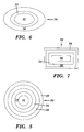
FIG. 6 shows a detail view of a second alternative embodiment of a sensor;
FIG. 7 shows a detail view of a third alternative embodiment of a sensor;
FIG. 8 shows a paving material profile;
FIG. 9 shows a circuit diagram of an alternative sensor circuit;
FIG. 10 shows a circuit diagram of another alternative sensor circuit; and
FIG. 11 shows a circuit diagram of another alternative sensor circuit.
DESCRIPTION OF THE PREFERRED EMBODIMENTS
While the preferred embodiments will be described in conjunction with the paving environment, other applications of the invention will become apparent to those skilled in the art. The limited description is intended only for ease of explaining the construction and operation of the device. Accordingly, “paving material” should be interpreted broadly to include all varieties of asphalt, cement, concrete, soil, sand, stones, bituminous material and all other forms of in-place material.
Referring to FIG. 1, a schematic view of a paving material analyzer system 10 is shown. System 10 includes a sensor 20 and an analyzer unit 22. Analyzer unit 22 preferably has a sensor circuit 24 and a data analyzer 28. Sensor circuit 24 is an electronic circuit that: 1) applies an electric potential to sensor 20 to generate, or transmit, an electrical field; and 2) receives the electrical field. Sensor circuit 24 preferably includes a guarded circuit 26. As will be described in greater detail below, data analyzer 28 may include a percentage compaction calculator 27, a display 29 and a correction system 30.
An exemplary structure of sensor 20 is shown in FIGS. 1 and 2. Sensor 20 may include an active inner element 32 surrounded by an intermediate ground element 34 which is surrounded by a first outer element 36 and a second outer element 38. As shown in FIG. 2, an electrical field 40 is created proximate paving material 42 by applying an electric potential (from electronic circuit 24 shown in FIG. 1) through sensor 20. Electrical field 40 is transmitted from sensor 20 via element 38 and/or element 36 into adjacent paving material 42. Sensor 20 may be in contact with paving material 42 during use. Inner element 32 then receives this electrical field signal from paving material 42, the signal having been altered by the impedance characteristics of paving material 42. Each of elements 32, 34, 36, 38 may be constructed of any conducting material, but are preferably made of copper, aluminum or steel. Elements are held together and insulated from each other by a non-conductive material such as an epoxy.
Turning to FIG. 3, in one embodiment, sensor circuit 24 preferably includes a transmitting circuit 44 and a receiving circuit 45. While preferred embodiments of these circuits have been illustrated, it should be noted that these circuits 24, 44, 45 may take a variety of forms. The embodiments disclosed for each should, therefore, not be taken as limiting the invention to any particular number or form of circuitry.
In the exemplary circuits shown in FIG. 3, transmitting circuit 44 is a constant voltage source circuit. Circuit 44 includes a square wave oscillator (crystal) 46 coupled to a high speed switch 48. A reference voltage 50 is supplied to an error amplifier 52 that is also coupled to high speed switch 48. An amplitude detector 54 is also coupled to error amplifier 52. A low pass filter 56 is provided at an output of high speed switch 48. Output of low pass filter 56 is the constant voltage sine wave output for sensor 20. Amplitude detector 54 also receives the output of low pass filter 56 and maintains the constant voltage output. The output to sensor 20 preferably has a frequency in the range of 200 kHz to 15 MHz. It should be recognized that while a preferred constant voltage source circuit has been illustrated, other systems that provide a constant voltage source are also possible. Accordingly, the invention should not be limited to any particular form of constant voltage source circuitry.
In the exemplary receiving circuit 45, a phase detector 47 and an amplitude detector 49 receive the electrical field signal back from sensor 20. Phase detector 47 is also coupled to an amplitude detector 54, which it may share with transmitting circuit 44. Phase detector 47 and amplitude detector 49 feed to a low pass filter 51 and a low pass filter 53, respectively. The outputs of low pass filters 51, 53 are coupled to data analyzer 28 for analysis of the electrical field signal.
Returning to FIG. 1, regardless of the type of sensor circuit 24 used, it is preferred that a guarded circuit 26 is included so sensor circuit 24 and sensor 20 are guarded. In this setting, guarded circuit 26 would be coupled to an additional element 74, shown in FIG. 5. Element 74 acts as a guard element for sensor 20. It has been found that this promotes accuracy because determinations are not subject to stray fields.
As also shown in FIG. 1, system 10 includes a data analyzer 28. In one embodiment, data analyzer 28 is a microcomputer configured to determine the density of paving material 42 based on the effect of the impedance characteristics of paving material 42 on electrical field 40. In particular, data analyzer 28 determines an impedance value of paving material 42, e.g., by comparing a transmitted electrical field signal versus a received electrical field signal that has passed through paving material 42. Data analyzer 28 uses the impedance value to determine a density value of paving material 42. Impedance has been found to be a more useful measure of density than predecessor systems'use of capacitance.
Data analyzer 28 is capable of determining paving material density in terms of: 1) variations in paving material density across a measurement area, and 2) actual density indications. In order to determine the density of paving material 42 in terms of variations in density, variations in impedance of electrical field 40 created by the impedance characteristics of paving material 42 are tracked.
In a preferred embodiment, however, data analyzer 28 is configured to mathematically provide actual density determinations, e.g., 140 lb/ft3, and output them to a display 29. Density mathematical algorithms used to determine actual density indications may be created by modeling empirical data. Empirical data may be produced, for example, by calibrating a given sensor at a preferred operational setting with regard to specific types of paving material at known compaction densities. Mathematical modeling of the relationships between the measured impedance and known compaction densities results in a way to accurately determine density from an impedance of a specific type of paving material. Different mathematical algorithms can be created for different paving material and/or different sensors to make system 10 more accommodating, as will be described in more detail below. As one with skill in the art will appreciate, there may be other mechanisms other than mathematical modeling to determine actual density values. For instance, it may be possible to simply use the empirical data as a database to determine density, i.e., use the data as a lookup table.
Data analyzer 28 may also include a percentage compaction calculator 27 that calculates a percentage of maximum compaction, or percentage of air voids, of a particular paving material from the determination of density. The percentage can then be outputted to display 29. The relationship of density to a compaction percentage may be determined in many ways. One example method is by dividing the density determination by a known maximum compaction density for a particular paving material 42 that has been inputted to data analyzer 28. Data analyzer 28 may also be configured to calculate a compaction percentage without a separate calculator 27, i.e., as part of its operations discussed above.
As shown in FIG. 1, data analyzer 28 may also include a correction system 30. Correction system 30 may include a number of correction subsystems 58, 64, 66, etc. for making corrections to an impedance determination and, hence, determination of density and percentage compaction.
A first preferred correction subsystem 58 is a moisture corrector that corrects for moisture 60 on a top surface 62 of paving material 42, as shown in FIG. 2. In particular, it has been found that an increase in the phase angle of the measured impedance is indicative of increased moisture 60 on a top surface 62 of paving material 42. Similarly to the overall density mathematical algorithms discussed above, moisture correction mathematical algorithms can be created by modeling empirical data of moisture content. A moisture content mathematical algorithm can then be appropriately factored into the density mathematical algorithm to correct for moisture content, i.e., by removing a moisture content factor from the density mathematical algorithm. As a result, more accurate density determinations are possible. As with the density mathematical algorithms, a number of moisture content mathematical algorithms can be created for different paving material and/or different sensors to make system 10 more accommodating. With the above moisture corrector 58, a system 10 can determine the density of paving material based on the effect on the electrical field caused by the impedance characteristics of the paving material and regardless of moisture presence on the paving material.
Any impedance determination completed by system 10 automatically includes a quantity that is attributable,solely to sensor 20, i.e., a sensor impedance. Accordingly, inaccuracies may result unless the sensor impedance is removed from the overall impedance determination. Sensor impedance may be created by a number of factors such as the type of a protective coating (not shown) that may be applied to sensor 20 and/or any air void that may be provided between a protective coating and sensor elements 32, 34, etc. Where a given system 10 will be used on only one paving material 42 and will not have a changeable sensor 20, a pre-set sensor impedance correction factor can be used to remove the pre-determined sensor impedance from the density mathematical algorithms. However, where system 10 may be used with different sensors 20, a sensor impedance corrector 64 is preferably provided as a second correction subsystem to remedy the problem. In this setting, a sensor impedance correction factor for each sensor may be predetermined, and a sensor selector 65 (FIG. 1) may be provided for choosing a given sensor and correction factor. Data analyzer 28 could then automatically correct for sensor impedance regardless of the sensor used. It should be recognized that other mechanisms for inputting a sensor impedance correction factor may be provided and not depart from the spirit of this invention. For instance, each sensor 20 may have a sensor impedance correction factor indicated thereon for input by a user into system 10. As an alternative, rather than simply providing a sensor impedance correction factor, sensor impedance corrector 64 may also operate to implement different density mathematical algorithms for each sensor that automatically account for sensor impedance.
Another correction subsystem 66 that may be provided is for selection of a particular paving material 42. For instance, if a particular paving material 42 is known to require special treatment by system 10, subsystem 66 could provide a paving material selector 67 (FIG. 1) so data analyzer 28 can automatically correct problems that may cause inaccuracies. In this setting, each common paving material would have a predetermined correction factor(s) associated therewith. Alternatively, paving material selector 67 may operate to implement different density mathematical algorithms for each paving material that automatically account for any necessary special treatment.
A temperature corrector 68 may also be provided as a correction subsystem. Temperature corrector 68 would include a thermometer 70 and would create a correction factor by way of a correction algorithm. For instance, it has been found that an increase in paving material temperature results in a higher density determination and that the density determination can be corrected by subtracting a density value proportional to paving material temperature.
Another correction subsystem that may be provided is a standoff distance corrector 78. As shown in FIG. 4, it is contemplated that sensor 20 can operate at a standoff distance from paving material 42. Capacitance caused by gap 72 between sensor 20 and paving material 42 can adversely affect the impedance determination and, hence, the density determination if not corrected. To remedy this problem, an additional standoff distance corrector 78 can be added that uses, for example, an RC oscillator system similar to that discussed in U.S. Pat. No. 5,900,736, which is hereby incorporated by reference. In another embodiment, shown in FIG. 4, a standoff distance corrector may include a mechanism 80 for measuring surface characteristics (e.g., texture, uniformity and segregation) and the distance of sensor 20 to paving material 42. In one embodiment, standoff distance corrector 78 (FIG. 1) includes a laser probe 82 (FIG. 4), which is focused on paving material 42. The reflection of the laser can be used to determine the distance from sensor 20 to paving material 42. Although the laser shown is set to detect an angle, which can be used to determine the distance, it should be recognized that other arrangements using a laser are possible. Laser probe 82 can also be used to determine a paving material surface characteristic profile 84, as shown in FIG. 8, as sensor 20 moves over paving material 42. Profile 84 may be used to sense characteristics such as segregation of paving material 42 and the general quality of the surface. Profile 84 may also be used to determine the distance of sensor 20 to paving material 42 by averaging the distances indicated in the profile. As an exemplary alternative (also shown in FIG. 4), standoff distance corrector 78 (FIG. 1) may include an ultrasonic unit 86. Once the distance is determined, a size of the space is determined and the capacitance due to the space can be determined and an appropriate correction to the total impedance made, thus giving a more accurate determination of the density of paving material 42. The capacitance due to the space may be determined by mathematical modeling, lookup tables, etc., similarly to the density calculations discussed above. Although exemplary mechanisms 80 for measuring the distance and surface characteristics have been described and illustrated, any now known or later developed device for providing such function can be used within the scope of the invention.
It should be recognized that, in some instances, maintaining sensor 20 parallel to paving material 42 may be required for accurate capacitance determination of space 72. However, undulations and the like in paving material 42 may make this difficult. One remedy for this problem includes the provision of additional mechanisms 80,for measuring the distance from sensor 20 to paving material 42. Using a number of mechanisms 80, an angle(s) of sensor 20 relative to paving material 42 can be determined such that a correction(s) can be implemented in the capacitance calculation. Another remedy includes controlled positioning of sensor 20 to maintain it substantially parallel to paving material 42, e.g., by use of one or more servo-mechanisms. This latter remedy may also require additional mechanisms 80 to determine when sensor 20 is not parallel with paving material 42. Other remedies may also be implemented to address this problem.
It is understood that analyzer unit 22 and its components can be realized in hardware, software, or a combination of hardware and software. Furthermore, analyzer unit 22 may be realized in a centralized fashion in one computer system, or in a distributed fashion where different elements are spread across several interconnected computer systems, e.g., data analyzer 28 can split into an impedance determining unit, a density determining unit, etc. Any kind of computer system—or other apparatus adapted for carrying out the methods described herein—is suited. A typical combination of hardware and software could be a general purpose computer system with a computer program that, when being loaded and executed, controls data analyzer 28 such that it carries out the methods described herein. The present invention can also be embedded in a computer program product, which comprises all the features enabling the implementation of the methods described herein, and which—when loaded in a computer system—is able to carry out these methods.
Computer program, software program, or planning software, in the present context mean any expression, in any language, code or notation, of a set of instructions intended to cause a system having an information processing capability to perform a particular function either directly or after either or both of the following: (a) conversion to another language, code or notation; (b) reproduction in a different material form.
Referring to FIGS. 5-7, a variety of sensors 20 having different numbers of elements are shown. For instance, a sensor 20 shown in FIG. 5 has an additional guard element 74, and a sensor 20 shown in FIG. 6 has outermost element 38 removed. When guard element 74 is provided, it is coupled to guard circuit 26 so that sensor circuit 24 and sensor 20 are guarded. Additional elements surrounding those described above, and structured in similar fashion as those above, may be used to make system 10 more stable. Additional elements are advantageous to make the electrical field more uniform or compensate for other parameters that may interfere with impedance measurement, e.g., known electromagnetic interference.
FIGS. 5-7 also illustrate how the shape and size of sensors can be selectively different. The examples shown are a circular shape in FIG. 5; an elliptical shape in FIG. 6; and a polygonal, i.e., rectangular, shape in FIG. 7. Adjustability of the shape and size of sensor 20 is advantageous to system 10 because the shape and size of sensor 20, inter alia, dictates the depth of penetration and area of electrical field 40 and, accordingly, the volume of the field of test. For instance, as illustrated in FIG. 4, operation of a smaller sized sensor 20 allows the depth of penetration to be reduced to D2 as opposed to the depth D1 shown in FIG. 2. Being able to accurately control the depth of penetration prevents imprecise determinations when the signal penetrates through a new lift coat into an underlying surface that may not have the same density.
Changing the shape and size of sensor 20 also allows for a variation of the shape of the area tested. For instance, when a user wishes to determine density at a joint between two new lift coats, he can now use, for example, a long rectangular sensor as shown in FIG. 7 to assure accurate sensing along the joint.
Although FIGS. 5-7 show sensors in three preferred shapes, sensor 20 may take a variety of alternative shapes. Furthermore, although the embodiments shown are fixed in nature, it is also envisioned to provide a sensor with an adjustable shape.
The provision of a constant voltage source circuit enables system 10 to detect material density with more accuracy and reliability than related art devices or the constant current source disclosed in U.S. Pat. No. 5,900,736. Constant voltage source circuit in sensor circuit 24 also provides a lower impedance sensor, which provides a stable system that is not alterable by environmental factors, e.g., electromagnetic interference. Accordingly, the potential for mismeasurement is reduced. Furthermore, system 10 is lightweight and allows for instantaneous and continuous determinations that reduces paving time. The provision of correction system 30 and its related subsystems makes system 10 even more accurate.
Referring to FIG. 9, an alternative sensor circuit 124 may include an inductor 126 that allows for improved accuracy. In one embodiment, inductor 126 is a variable electronic inductor, e.g., based on an active operational amplifier circuit. Inductor 126 as controlled by data analyzer 28 is adapted to null a capacitive reactance portion of the impedance by applying a known inductive reactance. That is, inductor 126 is configured to be variable by data analyzer 28, e.g., by applying a known voltage, to cancel the capacitive reactance portion of the impedance leaving only the non-reactive portion of the impedance, i.e., a resistance portion. In this setting, data analyzer 28 functions to determine a total impedance of paving material 42 based on the non-reactive portion, the known inductive reactance portion and a known operating frequency of circuit 124. In particular, data analyzer 28 can determine the value of the unknown capacitance from the known value of the inductive reactance portion and the operational frequency. The total impedance is then based on the capacitive reactance, inductive reactance and the non-reactive portion (resistance). As discussed above, the density of the paving material can be determined based on the total impedance.
In one embodiment, shown in FIG. 9, alternative sensor circuit 124 is implemented with substantially the same transmitting circuit 44 as that shown in FIG. 3. Receiving circuit 145 is provided with a phase (Φ) detector 132, a first multiplier 134 and a second multiplier 136 that receive the electrical field signal from sensor 20. Phase detector 132 is also coupled to an amplitude detector 54, which it may share with transmitting circuit 44. Phase detector 132 also feeds to each multiplier 134 and 136. First multiplier 134 feeds a capacitive reactance signal (Xc=Z sin Φ) to a phase comparator 138. Phase comparator 138 feeds to a null generator 140 and variable electronic inductor 126. Null generator 140 also feeds to variable electronic inductor 126. Inductor 126 feeds back to phase detector 138 an inductive reactance signal XL. Second multiplier 136 feeds back to data analyzer 28 a non-reactive portion (resistance) of impedance (R=Z cos Φ). Null generator 140 also feeds back to data analyzer 28 a signal that can be used to determine the inductive reactance portion and, hence, the resultant capacitive reactance of the paving material 42. As discussed above, data analyzer 28 calculates total impedance and density based on the above information.
Referring to FIGS. 10 and 11, square wave oscillator 46 of transmitting circuit 44 may be replaced in the above sensor circuits 24 (FIG. 3) and 124 (FIG. 9) with a variable oscillator 146 (ƒ(ω)1 n), which provides increase applicability. Frequency can then be varied, for example, in a sweep fashion or multiplexed to provide a number of sequential frequency signals. In any case, each of the other parts shown are configured to operate at whatever frequency or range is implemented. FIG. 10 shows a variable oscillator 146 implemented on sensor circuit 24 of FIG. 3, and FIG. 11 shows a variable oscillator 146 implemented on sensor circuit 124 of FIG. 9.
The invention also includes a method for analyzing paving material using the above-described system(s). The method includes the steps of determining an impedance of the paving material; and determining the density of the paving material based on the impedance determination of the paving material. The step of determining an impedance may include: providing a sensor; applying an electric potential through the sensor to generate an electrical field proximate the paving material; receiving the electrical field from the paving material; and determining an impedance of the paving material based on the effect of impedance characteristics of the paving material on the electrical field.
The step of determining an impedance may also include correcting the determination for an impedance of the sensor, and correcting the determination for moisture on a top surface of the paving material. The correction for moisture is preferably provided by monitoring a phase angle of the impedance to determine moisture on a top surface of the paving material, and correcting the impedance determination accordingly. An alternative step would be to calculate a percentage of full compaction of the paving material.
An alternative method for analyzing paving material may include the steps of: determining an impedance of the paving material; determining a capacitance of a space between a sensor and the paving material; and determining the density of the paving material based on the impedance determination of the paving material and the capacitance of the space. The correction steps discussed above may also be included as part of this alternative method.
While this invention has been described in conjunction with the specific embodiments outlined above, it is evident that many alternatives, modifications and variations will be apparent to those skilled in the art. Accordingly, the preferred embodiments of the invention as set forth above are intended to be illustrative, not limiting. Various changes may be made without departing from the spirit and scope of the invention as defined in the following claims.

Claims (11)

We claim:
1. A method for analyzing paving material comprising the steps of:
determining an impedance of the paving material;
determining a capacitance of a space between a sensor and the paving material by measuring a distance of the sensor to the paving material and determining the capacitance based on the distance; and
determining the density of the paving material based on the impedance determination of the paving material and the capacitance of the space.
2. The method of claim 1, wherein the step of determining an impedance of the paving material includes:
providing a sensor;
applying an electric potential to the sensor to generate an electrical field proximate the paving material;
receiving the electrical field from the paving material; and
determining an impedance of the paving material based on the effect of impedance characteristics of the paving material on the electrical field.
3. The method of claim 2, wherein the step of determining the impedance of the paving material includes nulling a capacitive reactance portion of the impedance.
4. The method of claim 1, wherein the step of determining an impedance of the paving material includes correcting the determination for an impedance of the sensor.
5. The method of claim 1, wherein the step of determining an impedance of the paving material includes correcting the determination for moisture on a top surface of the paving material.
6. The method of claim 5, wherein the step of correcting includes monitoring a phase angle of the impedance to determine moisture on a top surface of the paving material.
7. A paving material analyzer system having a sensor operatively coupled to an electronic circuit for generating an electric field proximate paving material end a data analyzer for determining a density of the paving material, the system comprising;
a standoff distance corrector that corrects the density for a distance of the sensor to the paving material,
wherein the standoff distance corrector includes a distance measurer configured to measure the distance of the sensor to the paving material and the standoff distance corrector determines a capacitance based on the distance.
8. The system of claim 7, wherein the distance measurer includes a laser probe.
9. The system of claim 8, wherein the standoff distance corrector also determines a paving material surface profile.
10. The system of claim 7, wherein the distance measurer includes a paving material contact and a Hall effect sensor coupled thereto.
11. The system of claim 7, wherein the electronic circuit includes means for determining an impedance of the paving material and nulling a capacitive reactance portion of the impedance.
US10/185,510 2000-05-04 2002-06-28 Paving material analyzer system and method Expired - Lifetime US6803771B2 (en)

Priority Applications (1)

Application Number Priority Date Filing Date Title
US10/185,510 US6803771B2 (en) 2000-05-04 2002-06-28 Paving material analyzer system and method

Applications Claiming Priority (2)

Application Number Priority Date Filing Date Title
US09/565,022 US6414497B1 (en) 2000-05-04 2000-05-04 Paving material analyzer system and method
US10/185,510 US6803771B2 (en) 2000-05-04 2002-06-28 Paving material analyzer system and method

Related Parent Applications (1)

Application Number Title Priority Date Filing Date
US09/565,022 Continuation-In-Part US6414497B1 (en) 2000-05-04 2000-05-04 Paving material analyzer system and method

Publications (2)

Publication Number Publication Date
US20020175691A1 US20020175691A1 (en) 2002-11-28
US6803771B2 true US6803771B2 (en) 2004-10-12

Family

ID=46279281

Family Applications (1)

Application Number Title Priority Date Filing Date
US10/185,510 Expired - Lifetime US6803771B2 (en) 2000-05-04 2002-06-28 Paving material analyzer system and method

Country Status (1)

Country Link
US (1) US6803771B2 (en)

Cited By (12)

* Cited by examiner, † Cited by third party
Publication number Priority date Publication date Assignee Title
US20040250612A1 (en) * 2001-09-19 2004-12-16 Laura Stridiron System for measuring material properties from a moving construction vehicle
US20050150278A1 (en) * 2003-10-24 2005-07-14 Troxler Electronic Laboratories, Inc. Pavement material microwave density measurement methods and apparatuses
US20050267700A1 (en) * 2004-05-26 2005-12-01 Gamache Ronald W Material analysis including density and moisture content determinations
US20060226857A1 (en) * 2005-03-18 2006-10-12 Troxler Electronic Laboratories, Inc. Apparatuses and systems for density gauge reference emulation
US20070046289A1 (en) * 2005-08-30 2007-03-01 Troxler Robert E Methods, systems, and computer program products for determining a property of construction material
US20080003057A1 (en) * 2006-06-29 2008-01-03 Hall David R Checking Density while Compacting
US20090194676A1 (en) * 2008-01-04 2009-08-06 Troxler Electronic Laboratories, Inc. Nuclear gauges and methods of configuration and calibration of nuclear gauges
US20150030392A1 (en) * 2012-04-06 2015-01-29 The Board Of Regents Of The University Of Oklahoma Method and apparatus for determining stiffness of a roadway
US9190183B2 (en) 2005-03-18 2015-11-17 Troxler Electronic Laboratories, Inc. Apparatuses and systems for density gauge calibration and reference emulation
US9902068B1 (en) * 2016-12-29 2018-02-27 Texas Instruments Incorporated Impedance signature analyzer to control automated actions
US10145837B2 (en) 2013-03-14 2018-12-04 Robert Ernest Troxler Systems and methods for asphalt density and soil moisture measurements using ground penetrating radar
EP3896438A1 (en) 2020-04-16 2021-10-20 Transtech Systems, Inc. Methods, circuits and systems for obtaining impedance or dielectric measurements of a material under test

Families Citing this family (9)

* Cited by examiner, † Cited by third party
Publication number Priority date Publication date Assignee Title
US8190338B2 (en) * 2008-09-02 2012-05-29 The Board Of Regents Of The University Of Oklahoma Method and apparatus for compaction of roadway materials
US20140167795A1 (en) * 2012-12-14 2014-06-19 Texas Instruments Incorporated Active feedback silicon failure analysis die temperature control system
PL2982951T3 (en) 2014-08-05 2019-04-30 Voegele Ag J Thermography module for road finishers
EP2990531A1 (en) * 2014-08-27 2016-03-02 Joseph Vögele AG System for road finisher with a temperature measuring device, method for determining a cooling behaviour und computer-readable storage medium
EP3245507B1 (en) * 2015-01-15 2019-11-06 Transtech Systems, Inc. Measurement and monitoring of physical properties of material under test (mut) from a vehicle
EP3495808A1 (en) 2017-12-05 2019-06-12 Airbus Helicopters A probe for non-intrusively detecting imperfections in a test object
US10494774B2 (en) * 2018-03-29 2019-12-03 Geophysical Survey Systems, Inc. Asphalt dielectric measurement accuracy improvement using asphalt surface temperature
CN111025285B (en) * 2019-11-01 2021-08-24 长安大学 Asphalt pavement water damage detection method based on map gray scale self-adaptive selection
CN114814183B (en) * 2022-05-27 2023-09-12 江苏新越沥青产业研发有限公司 Rapid nondestructive testing device for compactness of asphalt pavement

Citations (35)

* Cited by examiner, † Cited by third party
Publication number Priority date Publication date Assignee Title
US3400331A (en) 1965-01-18 1968-09-03 Pratt & Whitney Inc Gaging device including a probe having a plurality of concentric and coextensive electrodes
US3671857A (en) 1970-04-29 1972-06-20 Karlis Alfredovich Bergmanis Device for measuring permittivity of materials
US3694742A (en) 1970-07-15 1972-09-26 Karlis Alfredovich Bergmanis Device for measuring permittivity of materials
US3781672A (en) 1971-05-10 1973-12-25 Drexelbrook Controls Continuous condition measuring system
US3784905A (en) 1972-11-29 1974-01-08 Soiltest Inc Apparatus for determination of the density of in-place materials by measurement of their dielectric strength
US3882381A (en) 1973-11-05 1975-05-06 Surface Systems System for detecting wet and icy surface conditions
US3967912A (en) 1974-03-18 1976-07-06 Parker Jimmy L Paver feed control
US4099118A (en) 1977-07-25 1978-07-04 Franklin Robert C Electronic wall stud sensor
US4389136A (en) 1981-01-23 1983-06-21 Seaman Nuclear Corporation Method of determining density
US4433286A (en) 1979-04-09 1984-02-21 Georgetown University Identification of materials using their complex dielectric response
US4468610A (en) 1982-04-14 1984-08-28 Penril Corp. Radio frequency apparatus for measuring moisture content of materials as a function of dielectric constant
US4604612A (en) 1982-08-03 1986-08-05 United Kingdom Atomic Energy Authority Ice detector
FR2593200A1 (en) 1986-01-20 1987-07-24 Blandin Yves Multi-function finisher
US4766369A (en) 1986-03-31 1988-08-23 The United States Of America As Represented By The Administrator Of The National Aeronautics And Space Administration Ice detector
US4817021A (en) 1985-01-24 1989-03-28 Commonwealth Scientific And Industrial Research Organisation Moisture and density determination
US4933853A (en) 1988-09-28 1990-06-12 Raytheon Company Ultrasonic grade and auger control
US4972154A (en) 1989-06-06 1990-11-20 Metriguard, Inc Apparatus and method for measuring wood grain angle
US5051026A (en) 1990-08-15 1991-09-24 Aw-2R, Inc. Controlled density paving and apparatus therefor
US5088854A (en) 1990-08-13 1992-02-18 Aw-2R, Inc. Paving joints
US5134380A (en) 1986-02-10 1992-07-28 Otakar Jonas Icing detector and method
US5138268A (en) 1990-08-15 1992-08-11 Steve Mulkey Thickness measuring system for nonconducting materials
US5210500A (en) 1990-04-11 1993-05-11 Flachglas Aktiengesellschaft Process for contactless measurement of the electrical resistance of a test material
US5213442A (en) 1990-08-15 1993-05-25 Aw-2R, Inc. Controlled density paving and apparatus therefor
US5223796A (en) 1991-05-28 1993-06-29 Axiomatics Corporation Apparatus and methods for measuring the dielectric and geometric properties of materials
US5309110A (en) 1992-03-04 1994-05-03 The Perkin Elmer Corporation Differential dielectric analyzer
US5363051A (en) 1992-11-23 1994-11-08 The United States Of America As Represented By The Administrator Of The National Aeronautics And Space Administration Steering capaciflector sensor
US5378994A (en) 1990-04-24 1995-01-03 Novak; James L. Non-contact capacitance based image sensing method and system
US5386196A (en) * 1993-08-23 1995-01-31 Denmar, Inc. System and method for accurate contactless measurement of the resistivity of a test material
US5398547A (en) 1989-01-10 1995-03-21 Innovative Dynamics, Inc. Apparatus for measuring ice distribution profiles
US5436565A (en) 1992-09-14 1995-07-25 The United States Of America As Represented By The Secretary Of The Navy Non-contacting capacitance probe for dielectric cure monitoring
US5484226A (en) 1994-01-18 1996-01-16 Caterpillar Paving Products Inc. Controlling apparatus for asphalt pavers
US5521515A (en) 1995-02-17 1996-05-28 The United States Of America As Represented By The Administrator Of The National Aeronautics And Space Administration Frequency scanning capaciflector for capacitively determining the material properties
US5602486A (en) 1994-03-14 1997-02-11 Sandia Corporation Impedance sensing of flaws in non-homogenous materials
US5900736A (en) 1997-07-28 1999-05-04 Transtech Systems, Inc. Paving material density indicator and method using capacitance
US6536553B1 (en) * 2000-04-25 2003-03-25 The United States Of America As Represented By The Secretary Of The Army Method and apparatus using acoustic sensor for sub-surface object detection and visualization

Patent Citations (36)

* Cited by examiner, † Cited by third party
Publication number Priority date Publication date Assignee Title
US3400331A (en) 1965-01-18 1968-09-03 Pratt & Whitney Inc Gaging device including a probe having a plurality of concentric and coextensive electrodes
US3671857A (en) 1970-04-29 1972-06-20 Karlis Alfredovich Bergmanis Device for measuring permittivity of materials
US3694742A (en) 1970-07-15 1972-09-26 Karlis Alfredovich Bergmanis Device for measuring permittivity of materials
US3781672A (en) 1971-05-10 1973-12-25 Drexelbrook Controls Continuous condition measuring system
US3784905A (en) 1972-11-29 1974-01-08 Soiltest Inc Apparatus for determination of the density of in-place materials by measurement of their dielectric strength
US3882381A (en) 1973-11-05 1975-05-06 Surface Systems System for detecting wet and icy surface conditions
US3967912A (en) 1974-03-18 1976-07-06 Parker Jimmy L Paver feed control
US4099118A (en) 1977-07-25 1978-07-04 Franklin Robert C Electronic wall stud sensor
US4433286A (en) 1979-04-09 1984-02-21 Georgetown University Identification of materials using their complex dielectric response
US4389136A (en) 1981-01-23 1983-06-21 Seaman Nuclear Corporation Method of determining density
US4468610A (en) 1982-04-14 1984-08-28 Penril Corp. Radio frequency apparatus for measuring moisture content of materials as a function of dielectric constant
US4604612A (en) 1982-08-03 1986-08-05 United Kingdom Atomic Energy Authority Ice detector
US4817021A (en) 1985-01-24 1989-03-28 Commonwealth Scientific And Industrial Research Organisation Moisture and density determination
FR2593200A1 (en) 1986-01-20 1987-07-24 Blandin Yves Multi-function finisher
US5134380A (en) 1986-02-10 1992-07-28 Otakar Jonas Icing detector and method
US4766369A (en) 1986-03-31 1988-08-23 The United States Of America As Represented By The Administrator Of The National Aeronautics And Space Administration Ice detector
US4933853A (en) 1988-09-28 1990-06-12 Raytheon Company Ultrasonic grade and auger control
US5551288A (en) 1989-01-10 1996-09-03 Innovative Dynamics, Inc. Measuring ice distribution profiles on a surface with attached capacitance electrodes
US5398547A (en) 1989-01-10 1995-03-21 Innovative Dynamics, Inc. Apparatus for measuring ice distribution profiles
US4972154A (en) 1989-06-06 1990-11-20 Metriguard, Inc Apparatus and method for measuring wood grain angle
US5210500A (en) 1990-04-11 1993-05-11 Flachglas Aktiengesellschaft Process for contactless measurement of the electrical resistance of a test material
US5378994A (en) 1990-04-24 1995-01-03 Novak; James L. Non-contact capacitance based image sensing method and system
US5088854A (en) 1990-08-13 1992-02-18 Aw-2R, Inc. Paving joints
US5051026A (en) 1990-08-15 1991-09-24 Aw-2R, Inc. Controlled density paving and apparatus therefor
US5213442A (en) 1990-08-15 1993-05-25 Aw-2R, Inc. Controlled density paving and apparatus therefor
US5138268A (en) 1990-08-15 1992-08-11 Steve Mulkey Thickness measuring system for nonconducting materials
US5223796A (en) 1991-05-28 1993-06-29 Axiomatics Corporation Apparatus and methods for measuring the dielectric and geometric properties of materials
US5309110A (en) 1992-03-04 1994-05-03 The Perkin Elmer Corporation Differential dielectric analyzer
US5436565A (en) 1992-09-14 1995-07-25 The United States Of America As Represented By The Secretary Of The Navy Non-contacting capacitance probe for dielectric cure monitoring
US5363051A (en) 1992-11-23 1994-11-08 The United States Of America As Represented By The Administrator Of The National Aeronautics And Space Administration Steering capaciflector sensor
US5386196A (en) * 1993-08-23 1995-01-31 Denmar, Inc. System and method for accurate contactless measurement of the resistivity of a test material
US5484226A (en) 1994-01-18 1996-01-16 Caterpillar Paving Products Inc. Controlling apparatus for asphalt pavers
US5602486A (en) 1994-03-14 1997-02-11 Sandia Corporation Impedance sensing of flaws in non-homogenous materials
US5521515A (en) 1995-02-17 1996-05-28 The United States Of America As Represented By The Administrator Of The National Aeronautics And Space Administration Frequency scanning capaciflector for capacitively determining the material properties
US5900736A (en) 1997-07-28 1999-05-04 Transtech Systems, Inc. Paving material density indicator and method using capacitance
US6536553B1 (en) * 2000-04-25 2003-03-25 The United States Of America As Represented By The Secretary Of The Army Method and apparatus using acoustic sensor for sub-surface object detection and visualization

Non-Patent Citations (3)

* Cited by examiner, † Cited by third party
Title
Atkins, R.T., Pangburn, T., Bates, R.E., and Brockett, B.E., "Soil Moisture Determinations Using Capacitance Probe Methodology," U.S. Army Cold Regions Research and Engineering Laboratory, Special Report 98-2, Jan. 1998.
Evaluation of Dielectric Measurement Apparatus For Determining Pavement Density, Jul. 1969, Prepared by Department of Highways State of Colorado-Planning and Research Division.
Time domain technique for low frequency dielectric measurements, J. Phys. E: Sci. Instrum., vol. 13 (1980); Printed in Great Britain (month unavaliable).

Cited By (52)

* Cited by examiner, † Cited by third party
Publication number Priority date Publication date Assignee Title
US7226239B2 (en) * 2001-09-19 2007-06-05 Ingersoll-Rand Company System for measuring material properties from a moving construction vehicle
US20040250612A1 (en) * 2001-09-19 2004-12-16 Laura Stridiron System for measuring material properties from a moving construction vehicle
US7575395B2 (en) 2001-09-19 2009-08-18 Volvo Construction Equipment Ab System for measuring material properties from a moving construction vehicle
US20070201951A1 (en) * 2001-09-19 2007-08-30 Ingersoll-Rand Company System for measuring material properties from a moving construction vehicle
US8847609B2 (en) * 2003-10-24 2014-09-30 Troxler Electronic Laboratories, Inc. Pavement material microwave moisture-density measurement methods and apparatuses
US10908096B2 (en) * 2003-10-24 2021-02-02 Troxler Electronic Laboratories, Inc. Pavement material microwave moisture-density measurement methods and apparatuses
US11740187B2 (en) 2003-10-24 2023-08-29 Troxler Electronic Laboratories Inc. Pavement material microwave density measurement methods and apparatuses
CN1981190A (en) * 2003-10-24 2007-06-13 特罗克斯勒电子实验有限公司 Pavement material microwave density measurement methods and apparatuses
US7239150B2 (en) 2003-10-24 2007-07-03 Troxler Electronic Laboratories, Inc. Pavement material microwave density measurement methods and apparatuses
US20070188177A1 (en) * 2003-10-24 2007-08-16 Troxier Electronic Laboratories, Inc. Pavement material microwave density measurement methods and apparatuses
EP2345890A2 (en) 2003-10-24 2011-07-20 Troxler Electronic Laboratories, Inc. Pavement material microwave density measurement methods and apparatuses
US20050150278A1 (en) * 2003-10-24 2005-07-14 Troxler Electronic Laboratories, Inc. Pavement material microwave density measurement methods and apparatuses
US8400168B2 (en) 2003-10-24 2013-03-19 Troxler Electronic Laboratories, Inc. Pavement material microwave density measurement methods and apparatuses
US20150028890A1 (en) * 2003-10-24 2015-01-29 Troxler Electronic Labs Pavement material microwave moisture-density measurement methods and apparatuses
CN1981190B (en) * 2003-10-24 2014-04-16 特罗克斯勒电子实验有限公司 Pavement material microwave density measurement methods and apparatuses
US20050267700A1 (en) * 2004-05-26 2005-12-01 Gamache Ronald W Material analysis including density and moisture content determinations
US7219024B2 (en) * 2004-05-26 2007-05-15 Transtech Systems, Inc. Material analysis including density and moisture content determinations
US7705614B2 (en) 2005-03-18 2010-04-27 Troxler Electronic Laboratories, Inc. Apparatuses and systems for density gauge reference emulation
US9190183B2 (en) 2005-03-18 2015-11-17 Troxler Electronic Laboratories, Inc. Apparatuses and systems for density gauge calibration and reference emulation
US20060226857A1 (en) * 2005-03-18 2006-10-12 Troxler Electronic Laboratories, Inc. Apparatuses and systems for density gauge reference emulation
US8071937B2 (en) 2005-08-30 2011-12-06 Troxler Electronic Laboratories, Inc. Methods, systems, and computer program products for measuring the density of material including a non-nuclear moisture property detector
US20230094204A1 (en) * 2005-08-30 2023-03-30 Troxler Electronic Laboratories, Inc. Methods, systems, and computer program products for determining a property of construction material
US20110035182A1 (en) * 2005-08-30 2011-02-10 Robert Ernest Troxler Methods, systems, and computer program products for measuring the density of material including a non-nuclear moisture property detector
US7928360B2 (en) 2005-08-30 2011-04-19 Troxler Electronic Laboratories, Inc. Methods, systems, and computer program products for measuring the density of material including a non-nuclear moisture property detector
US20090314090A1 (en) * 2005-08-30 2009-12-24 Robert Ernest Troxler Methods, systems, and computer program products for determining a property of construction material
US8011248B2 (en) 2005-08-30 2011-09-06 Troxler Electronic Laboratories, Inc. Methods, systems, and computer program products for determining a property of construction material
US20070046289A1 (en) * 2005-08-30 2007-03-01 Troxler Robert E Methods, systems, and computer program products for determining a property of construction material
US8984946B2 (en) 2005-08-30 2015-03-24 Troxler Electronic Laboratories, Inc. Methods, systems, and computer program products for determining a property of construction material
US7820960B2 (en) 2005-08-30 2010-10-26 Troxler Electronic Laboratories, Inc. Methods, systems, and computer program products for measuring the density of material including a non-nuclear moisture property detector
US11531019B2 (en) 2005-08-30 2022-12-20 Troxler Electronic Laboratories, Inc Methods, systems, and computer program products for determining a property of construction material
US7569810B1 (en) 2005-08-30 2009-08-04 Troxler Electronic Laboratories, Inc. Methods, systems, and computer program products for measuring the density of material
US10928376B2 (en) 2005-08-30 2021-02-23 Troxler Electronic Laboratories, Inc. Methods, systems, and computer program products for determining a property of construction material
US7581446B2 (en) 2005-08-30 2009-09-01 Troxler Electronic Laboratories, Inc. Methods, systems, and computer program products for determining a property of construction material
US20080003057A1 (en) * 2006-06-29 2008-01-03 Hall David R Checking Density while Compacting
US7591608B2 (en) * 2006-06-29 2009-09-22 Hall David R Checking density while compacting
US20090250599A1 (en) * 2008-01-04 2009-10-08 Troxler Electronic Laboratories, Inc. Nuclear gauges and related methods of assembly
US11313983B2 (en) 2008-01-04 2022-04-26 Troxler Electronic Laboratories, Inc. Nuclear gauges and methods of configuration and calibration of nuclear gauges
US20090194676A1 (en) * 2008-01-04 2009-08-06 Troxler Electronic Laboratories, Inc. Nuclear gauges and methods of configuration and calibration of nuclear gauges
US20090274275A1 (en) * 2008-01-04 2009-11-05 Troxler Electronic Laboratories, Inc. Nuclear gauges and related methods of assembly
US9958562B2 (en) 2008-01-04 2018-05-01 Troxler Electronic Laboratories, Inc. Nuclear gauges and methods of configuration and calibration of nuclear gauges
US8164048B2 (en) 2008-01-04 2012-04-24 Troxler Electronic Laboratories, Inc. Nuclear gauges and methods of configuration and calibration of nuclear gauges
US8410423B2 (en) 2008-01-04 2013-04-02 Troxler Electronic Laboratories, Inc. Nuclear gauges and related methods of assembly
US9063062B2 (en) 2008-01-04 2015-06-23 Troxler Electronic Laboratories, Inc. Nuclear gauges and methods of configuration and calibration of nuclear gauges
US10520614B2 (en) 2008-01-04 2019-12-31 Troxler Electronic Laboratories, Inc. Nuclear gauges and methods of configuration and calibration of nuclear gauges
US8716650B2 (en) 2008-01-04 2014-05-06 Troxler Electronic Laboratories, Inc. Nuclear gauges and related methods of assembly
US20150030392A1 (en) * 2012-04-06 2015-01-29 The Board Of Regents Of The University Of Oklahoma Method and apparatus for determining stiffness of a roadway
US11346835B2 (en) * 2013-03-14 2022-05-31 International Research Institute CiRI Systems and methods for asphalt density and soil moisture measurements using ground penetrating radar
US10145837B2 (en) 2013-03-14 2018-12-04 Robert Ernest Troxler Systems and methods for asphalt density and soil moisture measurements using ground penetrating radar
US10514348B2 (en) * 2016-12-29 2019-12-24 Texas Instruments Incorporated Impedance signature analyzer to control automated actions
US20180186006A1 (en) * 2016-12-29 2018-07-05 Texas Instruments Incorporated Impedance signature analyzer to control automated actions
US9902068B1 (en) * 2016-12-29 2018-02-27 Texas Instruments Incorporated Impedance signature analyzer to control automated actions
EP3896438A1 (en) 2020-04-16 2021-10-20 Transtech Systems, Inc. Methods, circuits and systems for obtaining impedance or dielectric measurements of a material under test

Also Published As

Publication number Publication date
US20020175691A1 (en) 2002-11-28

Similar Documents

Publication Publication Date Title
US6803771B2 (en) Paving material analyzer system and method
US6414497B1 (en) Paving material analyzer system and method
US5900736A (en) Paving material density indicator and method using capacitance
US7219024B2 (en) Material analysis including density and moisture content determinations
US7944220B2 (en) Moisture content sensor and related methods
US6982562B2 (en) Multiple frequency grain moisture sensor for combines
US4070612A (en) Method and apparatus for measuring terrain resistivity
US7205769B2 (en) Method and apparatus for processing a signal received by an electromagnetic prober
JP4526043B2 (en) Measuring apparatus and measuring method for measuring dielectric properties of products, in particular humidity and / or density
US9687169B2 (en) System, controller, and method for determining conductance of an object
JP4060315B2 (en) Material segregation, density, and moisture analysis apparatus and method
JPH03189503A (en) Apparatus and method for measuring thick- ness of coating
US6400161B1 (en) Material segregation and density analyzing apparatus and method
JP2018502312A (en) Measurement and monitoring of physical properties of materials under test from vehicles
Chew et al. Design and calibration of a large broadband dielectric measurement cell
Kuklin Device for the field measurements of frequency-dependent soil properties in the frequency range of lightning currents
Vinogradova et al. Selection of method and means of measuring resonant frequency of serial oscillatory circuit
Gruzdev et al. Determining the field of application of the noncontact resistivity technique
Bhunjun et al. Sensor system for contactless and online moisture measurements
US8244494B2 (en) Plasma insensitive height sensing
US11408835B2 (en) Microwave soil moisture sensor based on phase shift method and independent of electrical conductivity of the soil
Yavna et al. The Moisture Uniformity Control of the Draining Soil Layers in the Roadbed Construction
NL2028809B1 (en) Sensor and system for monitoring a substrate
SU379864A1 (en) DEVICE FOR MEASURING THE MOISTURE OF SOIL-GROUND
Huan et al. Soil Moisture Content Detection Based on Sensor Networks

Legal Events

Date Code Title Description
AS Assignment

Owner name: TRANSTECH SYSTEMS, INC., NEW YORK

Free format text: ASSIGNMENT OF ASSIGNORS INTEREST;ASSIGNORS:SOVIK, ROBERT A.;HOSTERMAN, RICHARD N.;MOROSS, GEORGE G.;REEL/FRAME:013062/0979

Effective date: 20020628

FEPP Fee payment procedure

Free format text: PAYOR NUMBER ASSIGNED (ORIGINAL EVENT CODE: ASPN); ENTITY STATUS OF PATENT OWNER: SMALL ENTITY

STCF Information on status: patent grant

Free format text: PATENTED CASE

FPAY Fee payment

Year of fee payment: 4

REMI Maintenance fee reminder mailed
FPAY Fee payment

Year of fee payment: 8

FPAY Fee payment

Year of fee payment: 12