US6785379B1 - Call management system with call control form user workstation computers - Google Patents
Call management system with call control form user workstation computers Download PDFInfo
- Publication number
- US6785379B1 US6785379B1 US09/340,379 US34037999A US6785379B1 US 6785379 B1 US6785379 B1 US 6785379B1 US 34037999 A US34037999 A US 34037999A US 6785379 B1 US6785379 B1 US 6785379B1
- Authority
- US
- United States
- Prior art keywords
- call
- call management
- management system
- user
- accordance
- Prior art date
- Legal status (The legal status is an assumption and is not a legal conclusion. Google has not performed a legal analysis and makes no representation as to the accuracy of the status listed.)
- Expired - Lifetime
Links
Images


Classifications
-
- H—ELECTRICITY
- H04—ELECTRIC COMMUNICATION TECHNIQUE
- H04M—TELEPHONIC COMMUNICATION
- H04M7/00—Arrangements for interconnection between switching centres
- H04M7/0024—Services and arrangements where telephone services are combined with data services
-
- H—ELECTRICITY
- H04—ELECTRIC COMMUNICATION TECHNIQUE
- H04M—TELEPHONIC COMMUNICATION
- H04M3/00—Automatic or semi-automatic exchanges
- H04M3/42—Systems providing special services or facilities to subscribers
- H04M3/42025—Calling or Called party identification service
- H04M3/42034—Calling party identification service
- H04M3/42059—Making use of the calling party identifier
-
- H—ELECTRICITY
- H04—ELECTRIC COMMUNICATION TECHNIQUE
- H04M—TELEPHONIC COMMUNICATION
- H04M3/00—Automatic or semi-automatic exchanges
- H04M3/42—Systems providing special services or facilities to subscribers
- H04M3/436—Arrangements for screening incoming calls, i.e. evaluating the characteristics of a call before deciding whether to answer it
-
- H—ELECTRICITY
- H04—ELECTRIC COMMUNICATION TECHNIQUE
- H04M—TELEPHONIC COMMUNICATION
- H04M3/00—Automatic or semi-automatic exchanges
- H04M3/42—Systems providing special services or facilities to subscribers
- H04M3/50—Centralised arrangements for answering calls; Centralised arrangements for recording messages for absent or busy subscribers ; Centralised arrangements for recording messages
- H04M3/53—Centralised arrangements for recording incoming messages, i.e. mailbox systems
- H04M3/533—Voice mail systems
Definitions
- This invention pertains to telephone switching systems in general.
- the focus of computer technology has become the desktop workstation computer attached to one or more business enterprisewide, high-speed digital networks which interconnect the workstation computers of business enterprise's employees with a variety of information servers, communications and computing devices.
- the business enterprise's digital network may be a combination of Local Area Networks LANs and Wide Area Networks WANs attached together via a variety of transmission media augmented by the Internet.
- These corporate communications worlds, i.e., business enterprise's digital networks and the public switched telephone network PSTN remain separate and distinct until now.
- a Call Management System for handling business communications.
- the system alters the architecture and philosophy of the past, providing the users an array of new features and functions and expanded existing features.
- a Call Management System provides for the real-time management of incoming voice calls by called parties.
- Real-time call management enables the called party to know who is calling before the call is accepted and, thus, to establish the likely priority of the call and decide how best to handle the call before his telephone rings.
- This method of call handling is intended to improve significantly the efficiency of the called party's interactions with customers, vendors, coworkers, and others.
- Each called party is notified via his/her computer terminal of each incoming call and the caller's identity, even when the called party's extension is already busy, allowing the called party to choose the appropriate handling of each incoming call before ringing the extension (hold, transfer, put through, send to voice. mail, etc.
- a call management computer intercepts telephone and data trunks which link the business to the telephone provider's central office.
- the call management computer interacts with and controls telephone and data trunks connecting with the telephone service provider.
- the call management computer receives and answers all calls from the telephone provider's central office, determines the type of call voice, fax, data, determines for whom the call is intended the called party, and proactively determines who is the calling party. This information determines how the call will be handled.
- Proactive caller identification is used to identify the caller by interacting directly with the caller to obtain an identifiable telephone number or the caller's spoken voice which are then identified through specialized primary or secondary Caller ID databases or a voice name database.
- Call alert information is transferred via operator or digital network interconnecting workstation computer to the called party's workstation, even when the called party's telephone extension is busy.
- the called party instructs the call management computer via the digital network what to do with the calls in progress.
- the call management computer also provides for call handling rules to be defined by the business organization or by the system users. These rules, called “VIP rules”, are an adjunct to the called party's direct control and provide for special handling of important individuals, groups or even for all callers.
- the call management computer either receives control commands from the called party or operates in accordance with an appropriate VIP rule and responds to the calling party accordingly by, for example, playing out recorded voice messages, receiving additional information from the caller, transferring the call to the called party, to voice mail or elsewhere either within or outside the organization.
- Call Management System provides system users with the many unique features and functions while requiring nothing more than simple “POTS” (plain old telephone service) telephones or headsets instead of expensive multi-button proprietary business telephone instruments.
- POTS plain old telephone service
- the Call Management System also functions as an outbound call processor, working in conjunction with software in each user's workstation to provide outbound call processing services.
- the personal call logs can be reviewed by a user and used to return missed phone calls through a point-and-click interface.
- a database containing caller identification information may also be used online for outdialing calls to selected people, all without the need for manual dialing.
- the Call Management System creates reusable “voice pathways” from the call management computer to the called party when it is appropriate to put a call through to a destination because of user selection or VIP rule processing. Voice pathways, once created, are reused repeatedly so long as the destination has calls in process. This enables rapid switching between calls with only the click of a workstation mouse and avoids the typical operation of establishing and tearing down entire calls in order to switch between them.
- Real-time protocol conversion is provided between central office trunks and PBX trunks of the Call Management System. This allows the system to receive new or different types of services from the telephone provider while still connecting to and utilizing existing telephone systems which cannot otherwise accept the new capabilities directly. It also permits the Call Management System to utilize directly the user's telephone instruments or headsets, removing the need for a separate PBX or other switch. “Conversion” between different trunk circuits allows the system's many new features and functions to be implemented without upgrade of the organization's legacy PBX or other switch or alternatively as a replacement for an existing PBX.
- the system monitors and controls the individual trunk circuits obtaining call content information and directly interacts with the caller to handle voice, Fax and data calls automatically in any combination.
- a Call Management System in accordance with the invention treats all calls external and internal in the same way, allowing the transferring and conferencing of calls from inside to outside, outside to outside, or in any other combination. This removes the historical limitations on the handling of calls depending upon their source.
- the Call Management System provides for the use of a single unique telephone number for each user. This “one number” is used to receive, identify and automatically handle all the user's voice, fax and data calls, one or several at a time using multiple trunk circuits. The use of only one number per user significantly reduces the costs, complexity, inefficiency and confusion of having multiple different telephone numbers for different functions.
- Proactive caller identification is provided by using direct system interactions with the calling party. Predetermined messages and acquired responses are used to identify the caller for the called party. This provides the system user and call management system with knowledge of who each caller is so that appropriate priority and special handling can be applied to each call.
- the call management computer automatically answers each call, identifies the called party, determines the call type and identifies the calling party.
- the call management computer alerts the called party system users through the organization's local area or wide area networks or via the Internet, providing the called party direct call control via their workstation.
- a system user can handle multiple calls at the same time, knowing who each caller is and applying appropriate priority to each call, eliminating “voice-mail-jail” since only humans, not machines, send callers to voice mail and reducing the incidence of “telephone tag”. This capability improves the user's ability to service multiple customers at the same time, as well as saves the time and costs of the otherwise inevitable “telephone tag”.
- VIP callers may be identified as “VIP” callers.
- special handling of the call is initiated.
- the special handling may include personalized voice messages in the user's own voice, user-generated voice “menus” for the caller, receipt of and routing based on caller-entered information, special call rerouting inside or outside, including “follow me” and “find-me” rerouting of the call to the user, even when the user is out of the office, and/or a distinctive ringing sound to alert the user.
- “Page me” or “Beep me” features are also included, even for calls which are routed to voice mail or elsewhere.
- the system routes or conferences calls from any station directly connected to the system, connected to the system via a PBX or other switch, or connected to the system via the public service telephone network or via Internet.
- the Call Management System views all sources and destinations as equivalent, only differing in their technological access requirements.
- “Call tags” which may be digital, text or voice messages, may be attached to voice calls by any system user to provide additional information to other system users to whom the call may be transferred or conferenced.
- the Call Management System identifies and automatically receives Fax and data calls directed to each individual system user. Once received and stored in the call management database, the user is alerted to the presence of the file and allowed to transfer it to his/her workstation for further examination or use. Likewise, Faxes or data files can be sent to selected or specified receivers through the Call Management System with individualized Fax banner information for each user.
- Summaries are maintained of all incoming and outgoing calls in an interactive, real-time, user-accessible “call log” portion of the Call Management Databases, allowing the called party to know who called, when they called, which calls were missed even if no voice mail or other form of message was left, and to return calls automatically through simple mouse clicks.
- a single telephone call can retrieve voice messages, e-mail, Fax and data messages even though in different forms and stored in different places.
- Users are provided a variety of retrieval mechanisms including: sending to a remote Fax machine anywhere in the world, or sending to a remote computer. This improves the ability for traveling and at-home users to stay in touch with all their information and thus their customers and prospects.
- Voice mail-jail is prevented because only humans, not machines, send callers to voice mail.
- the Call Management System transfers callers to voice mail when system users request or because of their VIP rules, it alerts users when voice mail exists for them to hear and it utilizes voice mail access to provide “One-Call Message Retrieval” of user's e-mail, voice mail, Fax, and data.
- the Call Management System monitors the current status of all system users and makes status information available to all other system users on demand.
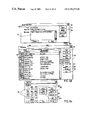
- FIG. 1 is a diagram of a Call Management System
- FIG. 2 is a block diagram of a call management computer
- FIG. 3 is a block diagram of a digital signal processor
- FIG. 4 is a detailed block diagram of a portion of the digital signal processor of FIG. 3;
- FIG. 5 is a diagram showing how callers are identified
- FIGS. 6 a through 6 e show components of the call management window as they appear at a workstation display
- FIG. 7 shows components of call management windows for VIP rule creation and management
- FIG. 8 shows a Fax handling display
- FIGS. 9 a and 9 b show components of call management windows
- FIGS. 10 a and 10 b show “copper bypass” configurations for Call Management System fault tolerance.
- FIG. 1 is an overall block diagram of one embodiment of the improved Call Management System, in which call control is provided by the user through a networked workstation computer, not a conventional telephone instrument.
- FIG. 1 shows the organization's environment with its Local Area Network and/or Wide Area Network (LAN/WAN), an on-site system user with a LAN/WAN based workstation, a PBX or similar switch, voice mail and a call management computer.
- LAN/WAN Local Area Network and/or Wide Area Network
- PBX Wide Area Network
- FIG. 1 an organization utilizing the Call Management System is clustered at the bottom of the figure and the outside world of callers and system users is clustered at the top.
- the organization's calls are handled using a call management computer which is placed so as to intercept telephone and data trunks between the telephone provider's central office and the organization's PBX or other switch (or as its replacement). Also shown are a work-at-home system user with workstation connected via the Internet, a voice caller at a pay phone as well as Fax and data callers all connecting through the public switched telephone network.
- call control is provided through a user workstation 114 to provide new and improved capabilities for the user and substantially eliminating the shortcomings and disadvantages of past systems.
- FIG. 1 shows pictorially the public switched telephone network (PSTN) with voice 118 , Fax 119 , a call management system 99 coupled to the public switched telephone network 100 through a telephone central office (CO) 103 .
- the call management system 99 includes a PBX or similar switch 104 and connections to user telephone instruments 106 .
- a digital data network 109 attaches to user workstation computers 114 a - 114 n .
- the digital data network of the illustrative embodiment is a conventional Local Area Network (LAN) or Wide Area Network (WAN).
- LAN Local Area Network
- WAN Wide Area Network
- the PSTN allows access to/from the call management system 101 via voice communication device 118 , fax device 119 , data 120 .
- a call management computer 101 is placed so as to attach to five 5 separate interfaces described below.
- Call Management System 99 is coupled to central office 103 via Central Office trunks 102 for both voice and data connections.
- CO trunks 102 includes a variety of trunks, including analog, DID, ISDN, T-1, DID over T-1, 800/900 T-1 services, data, and Internet.
- the central office 103 is interconnected within the public switched telephone network 100 via Local Exchange Carriers, Inter-exchange long-distance Carriers, Cable companies, RF or satellite carriers, digital Internet providers or any other types of voice or data carriers.
- CO trunks 102 may include multiple individual “circuits” ISDN, T-1, etc. which carry voice and/or data for individual calls.
- CO trunks include Internet connections.
- Call management computer 101 is configured and programmed to appear to telephone service providers 103 as though it is a business PBX or other business telephone switch and/or an Internet or other data server or node.
- PBX trunks 105 are the means by which the Call Management System 101 provides voice or data connections to system users or workstations or other devices within the business 99 .
- CO trunks For traveling or work-at-home users 111 , access to the outside using CO trunks is considered just a part of PBX trunk access, e.g., voice calls to an at-home system user's 111 telephone 106 p or Internet voice or data connections.
- PBX includes a variety of different telephone switches including classical private branch exchanges PBXs, automatic call directors ACDs, key telephone sets, or integrated switches within the call management computer 101 .
- Telephone instrument 106 a - 106 n as shown as physical telephones but may also include headsets, earpieces, computer sound systems, isochronous network technology such as isoEthernet and ATM, and other means of providing a voice or data connection to a user.
- the call management computer 101 may attach to the organization's PBX or other telephone switch 104 through PBX trunks 105 .
- the call management computer can sit in front of virtually any type of switch. No switch-specific hardware or software is required for integration.
- PBX trunks 105 may be analog, DID, DISA, ISDN, T-1, DID over T-1, 800/900 T-1 services or other available types. in all available variations and combinations.
- the call management computer 101 may be connected directly to the organization's telephone instruments 106 a - 106 n or directly to the user's workstation 114 a - 114 n for voice or data connections in place of a switch 104 .
- PBX trunks may or may not be of the same kind and/or number as the CO trunks 102 .
- the Call Management System may provide a one-to-one direct relationship between CO trunks 102 and PBX trunks 105 or it may provide protocol “conversion” between differing CO and PBX trunk types and/or numbers.
- PBX trunks also include direct connections to the user's telephone instruments 106 .
- the call management computer 101 is so configured and programmed that it appears to the business PBX or other switch as though it is a central office and/or it appears to the direct telephone instruments 106 a - 106 n as though it is a business PBX switch such as 104 .
- Trunk interfaces 203 , 206 , circuit switches 204 and DSP digital signal processors 208 interact with and control the CO and PBX trunks under the overall control of the call management computer 101 .
- All CO trunks 102 and PBX trunks 105 are attached to the call management system through appropriate trunk interfaces 203 and PBX trunk interfaces 206 .
- the interfaced trunk signals are further attached through circuit switches 204 and high-speed telephony buses 210 to each other and to special DSP's 208 .
- the configuration of the call management computer 101 with individual interface boards 203 , circuit switches 204 , DSP processors 208 and the high-speed buses 210 provide means for real-time sensing, switching and management of calls and the means for the call management computer 101 to appear to the central office 103 , through the CO trunks 102 , 202 , as a business PBX 104 or other switch and/or a server computer for data functions.
- This configuration further permits computer 101 to appear to the business PBX or other switch 104 or to the user's telephone instrument through the PBX trunks 105 , 205 as a central office switch such as 103 and/or a data server.
- Notification of events and control over multiple calls is accomplished independently of the organization's PBX or other switch system even if the user's telephone instrument 106 a - 106 n is currently busy because the digital networks 109 are separate from and independent of the user's telephone instrument 106 or telephone system 104 .
- the call management computer 101 attaches to the organization's digital data network including a LAN as well as Internet and/or other external WAN networks such as Internet via interfaces. 209 , 213 and 214 , through which it has immediate access to the user workstations, whether in-the-office 113 or at the site of a remote user 111 . These networks operate independent of whether the user's telephone instrument 106 is busy or not.
- the digital networks 109 are used by the call management computer 101 to alert called users such as users 111 and 113 to incoming voice calls and newly received Fax, voice or data messages and for receiving back user controls of all types from the user's workstation 114 .
- the digital networks 109 provides access to the organization's LAN server computers 110 for e-mail, voice mail, database, Internet access and other services.
- the call management system 101 utilizes a variety of interactive call management databases 215 for functions including: system and user configurations, primary and secondary caller identifications and voice caller identification, VIP rules, phone directories, Fax and data file storage, voice message storage, user-accessible call logs and many other functions.
- These on-line, real-time databases 215 may reside on the call management computer 101 itself or elsewhere on the digital network, e.g., on a LAN-based database server 110 .
- the Call Management System structure of the embodiment includes call management computer 101 , the CO Trunks 102 , the PBX Trunks 105 , the trunk interfaces 203 , circuit switching 204 and DSP processing 208 , the organization's digital network(s) 109 , 209 and the call management databases 215 .
- implementation may be in various combined or extended ways, such as when the call management computer 101 is built into the central office 103 or into a PBX or similar switch 104 .
- the call management computer 101 may replace the PBX and control the organization's telephone instruments 106 directly.
- the call management computer 101 is configured as shown in FIG. 2 . It is based on an industry-standard computer with processors, memory, power supply and cabinetry.
- the computer 101 is coupled to a data bus 211 .
- the data bus has connections to LAN interface 209 and disk memory which stores Call Management Databases 215 .
- the databases may alternatively reside on the digital network system 109 .
- the data bus 211 is connected to interfaces for Digital Internet connections 213 and bulk calling line identification BCLID data link 214 to the central office.
- the telephony subsystem ties together the CO trunk 102 and PBX trunks 105 through their specific trunk interfaces 203 , 206 and circuit switches 204 to the telephony signal buses 210 .
- Each of the trunk interfaces 203 , 206 is also coupled to the computer data bus 211 , through which the computer processors 201 receive information and provide control and data to both the CO trunk interface 203 and its circuit switches 204 .
- the DSP digital signal processors 208 include multiple DSPs. The multiple DSPs as needed are attached to the telephony signal buses 210 through switches 204 and to the computer data bus 211 through which they provide information to the computer processor 201 and receive back control and data e.g. voice messages to play out Lo the caller.
- voice interface board 207 is connected to the computer data bus 211 and through its own circuit switches 204 to the telephony signal bus 210 , through which the voice connections can be made to/from any telephone instrument 106 .
- Typical call paths 121 , 221 are shown on FIGS. 1 and 2.
- the in-band call information from central office 103 is sent through a CO trunk 102 to the call management computer 101 where it attaches through an appropriate CO trunk interface 203 and circuit switch 204 to the telephony signal buses 210 .
- the call management system assigns one or more DSP processors 208 connected to the telephony signal bus 210 , to provide a monitoring and control link 219 for that call.
- An incoming call such as from the payphone caller 118 or the Fax caller 119 or data callers 120 is routed through the PSTN 100 to the central office 103 and then to the call management system 99 through a CO trunk 102 .
- the assigned DSP 208 and/or CO interfaces 203 monitor for an incoming call analog or digital signals in any available form, appropriate to the type of trunk and/or circuit.
- the call setup commands are recognized through the trunk interface 203 or through the associated DSP 208 and the call management computer processors 201 receives this information via the trunk interface 203 or DSP 208 connections to the computer signal buses 211 .
- Control signals from the call management computer 101 then cause the call to be answered via the same route according to the trunk and circuit type.
- a first call path segment 221 a to a DSP monitoring and control link 219 for the trunk and circuit terminates at the assigned DSP 208 .
- Connections to a system user 113 are created by the call management computer 101 selecting an available, appropriate CO trunk inbound 105 and establishing a call to the PBX 104 or to remote system users over additional trunk 102 to the central office 103 .
- the PBX 104 or CO 103 responds to the call setup commands depending upon the type of trunk and circuit (including voice-over-Internet and other digital services). These are sensed by the trunk interface 203 or 206 or the assigned DSP 208 and passed to the call management computer 101 .
- Call management computer 101 then controls the appropriate circuit switches 204 to connect the voice pathway from the calling party 118 to the voice pathway to the called party's 113 telephone instrument 106 or via a second call path segment which includes segment 218 and call path segment 221 b , leaving the assigned DSP 208 attached to continue providing the DSP monitoring and control link 219 .
- the call is then put through in a conventional manner by the PBX 104 or CO 103 to the called party's 113 or 111 telephone instrument 106 a or 106 p where it rings and is answered by the called party 113 or 111 completing the connection between the caller 118 and the called party 113 , 111 .
- the typical call path 221 with the associated DSP monitoring and control link 219 is then completed as shown.
- the voice pathway so created may be reused as described below.
- the CO trunk interfaces 203 and PBX trunk interfaces 200 and assigned DSP 208 remain active throughout a call or series of calls to a destination, watching for either end to terminate the call, by hanging up the telephone instrument, or otherwise changing the call state while the call management computer 101 watches for the system users 111 , 113 to select a command changing the call's state.
- Calls are originated by system users through their workstation 114 . Such originated calls may be destined to any system user 113 , 111 , a non-system user, or anywhere else in the PSTN 100 .
- the call management computer 101 selects an available, appropriate CO trunk 102 or PBX trunk 105 and establishes the call to the CO 103 or to the PBX 104 or the telephone instrument 106 using appropriate signaling techniques for that trunk or circuit.
- the call management computer 101 then instructs the circuit switches 204 to connect the call circuits together, “bridging” the originator to the destination and creating the typical call path 118 in FIG. 1 and DSP monitoring and control link 119 as shown in FIG. 2 .
- the CO trunk interface 203 , the PBX trunk interface 206 and assigned DSP 208 remain active throughout each call, monitoring for either end to terminate the call, by hanging up the telephone instrument, or otherwise to change the call state while the call management computer 101 monitors for the system user 111 , 113 to select a command changing the call's state.
- the call management computer 101 manages the available, appropriate CO and PBX trunks 102 , 202 , 105 , 205 so as to share between non-system user calls established from the PBX or telephone instruments and system user 113 , 111 calls established by itself.
- the call management computer software runs under Microsoft's Windows NT operating system, a multi-threading, multi-tasking operating system required by the real-time call management aspects of the system.
- the Call Management System may be configured as a “client” to the organization's existing digital networks or as a “server” when incorporating Internet or other server functions for the digital network(s).
- the Call Management System uses only a single DID (direct in dial) or extension number to receive all calls, voice, fax or data in any mixture and number within the limit of the number of available trunks and circuits at any time or all at the same time.
- the call management computer 101 is programmed to sort them out and handle each appropriately.
- the call management computer 101 determines a destination party for the call, either automatically through reception of DID, DNIS (dialed number identification service), ISDN or other signals or messages from the central office 103 as detected by the trunk interface 203 or the assigned DSP 208 or, alternatively, a call attendant feature of the Call Management System.
- DID dialed number identification service
- DNIS dialed number identification service
- ISDN ISDN or other signals or messages from the central office 103 as detected by the trunk interface 203 or the assigned DSP 208 or, alternatively, a call attendant feature of the Call Management System.
- the call management computer 101 instructs the DSP 208 to play out one or more voice messages from the call management database 215 asking the caller 118 to identify the destination party by name, spelling, extension number or otherwise.
- the DSP 208 receives the information from the calling party 118 and passes it to the call management computer 101 where the called party 111 or 113 is identified through the digits entered, through voice recognition or otherwise.
- the called party's extension number is found or verified using the call management database 215 .
- the caller For voice over Internet or similar techniques, the caller is provided and fills in a “form” which includes: the name of the caller, the name of the called party and other appropriate information.
- the incoming call type voice, Fax or data is also determined using the DSP 208 , which searches for appropriate signaling from the call source 118 e.g. none for voice, or CNG for Fax, specified DTMF, carrier or other signals for data whether files, video data, video conferencing, etc. in analog or digital form.
- the attached DSP 208 is instructed to switch to the appropriate Fax or data mode and to receive the transmission automatically for storage in the call management database 215 and later use by the called party 111 , 113 or to transfer the call automatically to an appropriate extension, e.g., for video conferencing.
- the identity of the voice caller 118 is determined either automatically through reception of Caller ID, ISDN, ANI, BCLID or other information from the central office 103 as received by the trunk interface 203 , the assigned DSP 208 , the BCLID data link 214 or otherwise. Depending upon what information was received, if any, Proactive Caller Identification may then use direct interaction with the caller 118 and the Caller ID databases 215 for additional information. Proactive Caller Identification is described in Section 6 and the Caller ID databases are described in Section 7 .
- VIP rules Specific rules, called “VIP rules”, are created to specify special handling for important callers, sets of callers or even for all callers. These VIP rules precede and augment direct user controls and are described in Section 10 .
- Voice calls destined for system users either working in the office 113 or outside the office 111 are handled by alerting the called party at his workstation 114 through sending a message from the call management computer 101 across the digital network 109 to the user's workstation 114 and thus to the user's call management window 115 which “pops up” onto the user's workstation screen. The user then controls the call through selections made using his call management window 115 and its subscreens. This procedure, the windows and the user's functions are described in Section 8 .
- the call management computer 101 , 201 handles these calls based first on any applicable VIP rules and then on commands from the user, via their workstation call management window 115 .
- a call is “held” and manipulated by the call management computer 101 throughout answering of a call, identification of the call type, identification of the called party, proactive identification of a calling party, playing out messages to the caller, receiving information received from the caller, VIP rule handling and/or notification of the called party 113 .
- the typical call pathway 221 , 219 is terminated at the assigned DSP 208 and is not passed beyond.
- call management window 115 Some of the call functions which may be exercised by a system user are described in the following paragraphs insofar as what happens with the call management computer 101 . Detailed descriptions of the call management window 115 and the user's functions, controls and management using their workstation 114 are provided in Section 8.
- a system user such as user 111 or 113 , may select the “Answer” function for a call announcement. If the user has no calls currently active, the call management computer 101 selects an available CO trunk (inbound trunk 105 for user 113 or outbound trunk 102 , for user 111 ) and establishes a call to the PBX 104 or the central office 103 . The PBX 104 or central office 103 responds to call setup commands depending upon the type of trunk and circuit.
- Call set up signaling is sensed by the trunk interface 203 or 206 or an assigned DSP 208 and passed to the call management computer 101 which then controls the appropriate circuit switches 204 to connect the voice pathway from the calling party 118 to the voice pathway 121 to the called party's 113 or 111 telephone instrument 106 a or 106 p , leaving the assigned DSP 208 attached as well to continue providing the DSP monitoring and control link 219 .
- the call is then processed conventionally by the PBX or CO to connect to the called party's 113 or 111 telephone instrument 106 a or 106 b where it rings and is answered by the called party 113 or 111 to complete the connection between the caller 118 and the called party 113 or 111 .
- the typical call path 221 with the associated DSP monitoring and control link 219 is then completed as shown.
- the voice pathways so created may be reused as described in Section 2.
- the voice pathway 121 already exists and the user's current call will be moved to “hold” or “hang Up” mode as defined by the user and the voice pathway switched immediately to the new caller (see “Transfer” below).
- the CO trunk interfaces 203 and PBX trunk interfaces 206 and assigned DSP 208 remain active throughout a call or series of calls to a destination, monitoring for termination of the call by either end through hanging up the telephone instrument or otherwise changing the call state.
- Call management computer 101 monitors for the system users 111 or 113 to identify selection of a command from the user's call management window 115 to change the call's state.
- the “Transfer” function is used to cause a received call to be transferred to another destination either inside the business 99 or to any destination coupled to the PSTN 100 . Transferring a call requires the user to select a “Speed-Transfer” button or a “Transfer” screen from which he may select a destination from a directory or the user may type in the phone number to use for the destination.
- the call management computer 101 receives a transfer message from a user's call management window 115 via the digital networks 109 , the call management computer 101 instructs switches 204 to disconnect the voice path 121 , instructs the appropriate trunk interface 206 to “hang up” the call to the user if appropriate and instructs the DSP 208 to return to call monitoring.
- call management computer 101 checks for any appropriate VIP rules for this calling party and the called party and processes the call as specified by the VP rules. Otherwise, call management computer 101 alerts the called party and awaits user control.
- the call management computer 101 establishes a new voice pathway to the destination wherever it may be, instructs the appropriate switches 204 to connect the voice pathways together 221 and controls the trunk interface 103 , 106 and the DSP 108 to monitor the progress of the call, searching for hang up or change of state at either end.
- One special function provided by the call management window 115 is to send a call to voice mail whether the call is active or not. This is a special variant of the “Transfer” function with a pre-specified destination.
- the Call Management System can conference calls independent of whether the parties are directly coupled to the PBX or are accessed via the central office 103 .
- a system user 113 selects the “Conference” function for an existing active call or with no active call, he then selects one or more destination parties from the call management window 115 directory and/or types in one or more telephone numbers.
- the call management window 115 sends a “Conference” message down the organization's digital network(s) 109 to the call management computer 101 , 201 , whereupon the call management computer 101 alerts the new system users.
- the call management computer 101 , 201 creates a new voice path 121 , as appropriate, instructs the appropriate circuit switches 204 to connect the voice paths together to the assigned DSP 208 , and instructs the DSPs to combine the signals appropriately to create a conference call.
- the call management computer 101 , 201 immediately establishes a call to the destination and “bridges” the circuits, as with “Outdial” calls described below.
- a system user can select the “Hold” function for any call currently active.
- the “Hold” messages are sent by the call management window 115 via the organization's LAN or WAN 109 to the call management computer 101 , call management computer 101 instructs the appropriate circuit switches 204 to break both the inbound and outbound portions of the voice path 121 effectively placing a caller on “hold” but providing the user rapid access to the call through simple mouse clicks.
- the Call Management System provides “Music on Hold” and/or corporate messages (sales, information, etc.). The caller can terminate any messages at any time by entering a “#”.
- a system user can select the “Mute” function for any call currently active. “Mute” messages are relayed via the call management window 115 and sent down the organization's LAN or WAIN 109 to the call management computer 101 which instructs the appropriate circuit switches 204 to break just the outbound portion of the voice path from the system user to the caller leaving the inbound portion active, thus muting the call.
- a system user can select the “Record” function for any call currently active.
- the “Record” messages are relayed via the call management window 115 and sent via the organization's digital network(s) 109 to the call management computer 101 which instructs the assigned DSP 208 to record the call content, sending it to the call management computer 101 which saves it to the Call Management Databases 215 for future replay.
- the call path 121 is dismantled by the call management computer 101 instructing the switches 204 to disconnect the voice path, instructing the appropriate trunk interface 203 or 206 and/or DSP 208 to “hang up” the call as appropriate and instructing the DSP to return to searching for a new call.
- the call management computer 101 instructing the switches 204 to disconnect the voice path, instructing the appropriate trunk interface 203 or 206 and/or DSP 208 to “hang up” the call as appropriate and instructing the DSP to return to searching for a new call.
- either end currently with new calls waiting is kept active as a re-usable voice pathway.
- the users of the system 99 may originate calls to other users located at business 99 or to any numbers outside the business 99 .
- the user utilizes his/her call control window 115 to identify or type in a destination for the call internal or external and then instructs the Call Management System to dial to that destination.
- Workstation 114 sends the dialing control messages via the digital network(s) 109 to the call management computer 101 , 201 which, in turn, causes the call to be placed using an available CO or PBX trunk/circuit 102 , 105 of the appropriate type through the circuit switches 204 .
- a voice path 121 is established to the calling party's telephone instrument 106 .
- the system user 11 , 113 has available all of the system features for originated calls, as for inbound calls.
- Calls received for business 99 employees who do not have appropriate workstations or who do not choose to be system users, or for the organization's voice operator and for dedicated Fax machines and other hardware devices are immediately switched by the call management computer 101 to the PBX 104 or telephone number dialed, and are handled conventionally.
- the call management computer 101 , 201 selects an available and appropriate PBX trunk 105 , establishes a call to the desired extension controls and the circuit switches 204 to connect the voice paths together.
- DSP 208 monitors progress of the call and monitors for either end to hang up. This process includes protocol conversion features for CO trunk/circuit 102 , which are of different type than the PBX trunk/circuit 105 .
- Fax or data calls received for specified numbers are accepted as though directed to a specified user, e.g., the organization's operator, who is then expected to sort out and the Faxes send them to the appropriate users or print them.
- the call management computer 101 receives the call establishment from the PBX 104 through the PBX trunk/circuit 105 and passes it on to the central office 99 via an available CO trunk circuit 102 , connecting the circuits together via appropriate circuit switches 204 .
- the user is unaware of this process and sees no difference from conventional telephone usage.
- the Call Management System provides a “CallBack” subsystem with which a calling party. places a call from a foreign telephone, the system receives the call and telephone number, then terminates the call and immediately dials the caller back at the number received. This process saves significant telephone expenses compared with the costs of calls from many foreign countries.
- the call management computer 101 When a call is put through to a system user, the call management computer 101 creates a reusable “voice pathway” 121 to the called party either an in-house user 113 or an external user 111 .
- Voice pathway switching rather than establishing and tearing down multiple separate calls, provides the ability to switch rapidly between multiple calls, on demand, based on the user's changing priorities through simple point-and-click mouse, keyboard or menu operations.
- FIG. 1 shows two re-usable voice pathways 121 , one to the “in-house” system user 113 via PBX trunks 105 and the organization's PBX 104 to the user's telephone instrument 106 and another to the “at-home or traveling” system user 111 via a CO trunk/circuit 102 to the central office 103 , and then via the PSTN 100 ultimately to the user's telephone instrument 106 .
- Both of these are valid cases, even though they utilize different CO and PBX trunks of any appropriate type.
- the Call Management System does not care whether the called party is at an in-house extension or is not directly connected to the call management system but is anywhere reachable via the PSTN or through voice over Internet or some other network.
- a voice pathway 121 is created by the call management computer 101 in any of a variety of ways:
- Playback of recorded voice messages may be done via a “Voice Pathway” created to the user's telephone instrument 106 or via the “Data Path” transferring the voice message to the user's workstation to be played out via the workstation's sound capability.
- the voice pathway 121 is used for the entire duration of that call and all other calls dialed or transferred to that same destination, until all such calls have been processed and the voice pathway is no longer needed.
- the calls being held in the call management computer 101 for that user may be rapidly “switched” 204 to a destination voice pathway 121 on demand as controlled by the user 113 or via the user workstation 114 through the call management window 115 .
- the central office trunk interfaces 203 , PBX trunk interfaces 206 and assigned DSP 208 remain active throughout a call or series of calls to a destination, monitoring for either calling or called party to terminate the call or otherwise change the call state.
- the call management computer 101 monitors for the system user 113 to request change of the call state, e.g., “hangup”, “Hold”, etc.
- the call path is dismantled by instructions to the circuit switches 204 and DSP 208 from the call management computer 101 .
- the call management computer 101 does not “hang up” that end of the call path 121 . Instead it is kept so that it may be re-used as a voice pathway for the waiting calls. Otherwise, the call management computer 101 instructs the trunk interface 203 , 206 and/or DSP 208 to “hang up” the call and return to waiting for another call to be presented.
- Voice pathway switching rather than requiring the establishment and tearing down of multiple separate calls as conventionally done, provides the ability to switch rapidly between multiple calls, on demand, based on the user's changing priorities.
- the Call Management System provides for real-time protocol conversion between central office trunk type 102 and number and PBX trunk/circuit 105 types and number.
- the number and type of central office trunk/circuits need bear no direct relationship with the number and type of PBX trunk/circuits. This conversion allows the Call Management System's new and expanded features and functions to be implemented using existing telephone systems which cannot otherwise accept new telephone capabilities directly or in a cost-effective manner.
- the call management computer 101 attaches to central office trunk/circuits 102 from one or more central offices 103 on the one side and through PBX trunk circuits 105 to the PBX 104 and/or directly to telephone instruments 106 .
- Each type of CO trunk and/or PBX trunk analog, analog DID, T-1, DID over T-1, ISDN, Internet or others is attached through its own appropriate type of interface board 203 , 206 which converts the trunk signals to standardized bus signals for the circuit switches 204 and telephony signal buses 210 and it also monitors various aspects of the call.
- ISDN PRI provides a good start toward automating proactive caller identification.
- New ISDN PRI services are provided by the central office 103 through the CO trunks 102 to the call management computer 101 , 201 where the circuits are “converted” to older analog DID services for the PBX trunks 105 to the organization's existing PBX adding all of the Call Management System features and functions without changing the organization's existing PBX investment.
- Conversion is made possible by the structure of the call management computer 101 with the logical and physical separation between trunks, where each different CO trunk 102 and PBX trunk 105 has its own unique trunk interface 203 and 206 which converts the unique trunk signals to standardized circuit signals for the circuit switches 204 and telephony signal bus 210 .
- the only thing that is common is that their voice paths can be connected together, when appropriate, using the circuit switches 204 and telephony signal buses 210 .
- trunks/circuits from one side is independent of and separate from the handling of trunks/circuits from the other, yet their voice paths can be connected together to complete the circuit whenever appropriate, coming in via one type of trunk interface, converting to standard signals and going out via an entirely different trunk interface being “Converted” en route.
- Real-time protocol and signal conversion thus provides a crucial enabling mechanism for all of the new features and functions of the Call Management System using information available through new types of telephone provider services, while still using an existing PBX which cannot otherwise support such services.
- the Call Management System only requires the legacy PBX to provide voice paths to user telephone instruments, to voice mail and other devices ignoring its other existing features.
- the Call Management System's unique “Intelligent” call management capabilities are based upon the real-time sensing, control, voice and data processing provided by the call management computer's 101 configuration of DSP processors 208 , central office trunk interfaces 203 , PBX trunk interfaces 206 and circuit switches 204 through which circuits calls are assigned to one or more DSP processors 208 at all times.
- the DSPs provide real-time DSP voice and data processing which is the essential means by which the content of each call is monitored and known.
- the Call Management System monitors call content and uses that information to provide “intelligent” call management, unlike conventional PBXs or other telephone switches, which strictly avoid knowledge of the call content and are conceptually limited to “call switching”.
- Each DSP subsystem consists of a DSP motherboard which attaches to the call management computer 101 , 201 via the computer signal buses 211 and to the telephony signal buses 210 through circuit switches 204 .
- the motherboard supports one to four DSP daughterboards of three DSP processors each 3, 6, 9 or 12 DSPs per subsystem with 100, 200, 300 or 400 MIPS of processing power.
- Each call management computer 101 , 201 utilizes one or more such DSP subsystems.
- DSP ADSP-2181 The commercially available Analog Devices DSP ADSP-2181 is used for the DSPs, operating at 16.67 Mhz 33 MIPS with 32K bytes of program RAM and 32K bytes of data RAM.
- DSP daughterboards are populated on the DSP motherboard as required to provide system support for broad categories of services:
- “Call Monitoring” DSPs are those assigned to support the actual number of existing CO and PBX trunks, monitoring and controlling individual calls e.g. call progress monitoring, voice playback, etc.
- Each call monitoring DSP in this implementation typically can handle four through circuits/calls both CO and PBX sides for a total of 12 to 48 pairs per DSP subsystem.
- Specific function DSPs provide special functions as required for each specific system e.g. voice recognition, text-to-speech, etc.
- DSPs can be assigned to any circuit/call as needed to support any particular function or set of functions.
- the DSP motherboard connects to the call management computer 101 through its interfaces with the computer signal buses 211 through which the call management computer's software drivers control, monitor and pass information between the call management computer processors and memory 201 , the call management databases 215 , the DSP motherboards and the DSP processors 208 on daughterboards.
- the DSP motherboard uses an industry standard PCI bus interface with industry-standard “plug-and-play” support:
- Each DSP has its own 32K bytes of dual-port shared RAM memory which it shares with the call management computer processors 201 .
- each daughterboard uses 96K bytes of shared memory and a fully-populated DSP subsystem uses 384K bytes of shared memory.
- the shared memory provides communications between the DSP and the call management computer's 101 , 201 software drivers and minimizes the overhead of system interruptions external memory delay states. Shared memory is used for:
- Each DSP operates with its own Multi-tasking software environment, sharing the available time and MIPS among a series of tasks. The number and choice of which tasks are active at any moment depends upon the state of each of several calls the DSP is handling. Each call is itself considered a “state” machine. These tasks include:
- Fax Group 3 reception and transmission including CNG tone generation and special Fax identification for reception and special Fax banner for transmission for each system user
- Each DSP motherboard also supports the following external connections:
- External audio microphone input which can be used for voice recording if desired
- FIG. 3 shows the DSP motherboard block diagram.
- the DSP motherboard functions primarily as an interface between the computer signal buses 211 , the telephony signal buses 210 , the DSP daughter boards and their DSPs 308 and internal decoders, sequencers and logic.
- This architecture utilizes common internal address and controls 315 and data 316 signals from the PCI interface 301 connecting the call management computer's 201 PCI bus 211 to essentially everything on the motherboard 208 and through it to the DSP daughterboards.
- Each motherboard 208 includes:
- the FMIC telephony bus circuit switches 204 which provide signal paths to/from the telephony signal buses 210 and the DSP processors 208
- the address counters 317 , chip select circuits 319 and address and memory sequencer 318 which manages the on-board controls
- DSP and FMIC controls are handled via DSP selects 320 , interrupt control register 321 and the mailbox and error register controls 322
- External audio input for music on hold and headset for debugging are provided 225 by a separate audio circuit.
- Each daughterboard interface consists of:
- FIG. 4 shows the DSP daughterboard.
- Each daughterboard 2081 , 2082 , 2083 , and 2084 attaches to the DSP motherboard 208 through the daughterboard interfaces address lines 315 , data lines 316 , telephony circuit buses 313 and status/error lines 314 .
- Each DSP 208 , 308 , 408 has its own dual-port RAM data memory 410 accessible either from the DSP or from the call management computer 101 , 201 via the PCI motherboard interface 301 .
- the call management computer's 101 , central office trunk interfaces 203 support one or more trunks per board, depending upon the type of trunks, with varying number of circuits per trunk typically 1 or 2 T-1 or ISDN PRI to 24 analog, DID or stations.
- the trunk interfaces 203 , 206 provide a variety of different connections, interfaces and features, as is appropriate for each different type, including the following central office and PBX connections:
- AnalogDID Reverse battery answer supervision identifying when the call is answered and when the station side disconnects
- the Telephony signal buses are based on the industry standard Multi-Vendor Integration Protocol (MVIP) which provide for 256 bi-directional voice/data channels, divided into 16 uni-directional or 8 bi-directional “streams” of 32 time slots each, operating at 2.048 Mhz.
- MVIP Multi-Vendor Integration Protocol
- the buses could just as well have been based on SCSA, PEB or other types of available standards or conventions_so long as “clear”, full-bandwidth circuit paths are provided among the trunk interfaces 203 , 206 , 207 , the DSPs 208 , and their circuit switches 204 .
- Trunk interfaces 203 , 206 , the Internet voice interface 207 , DSP 208 and others boards connect to the telephony signal buses 211 through their own circuit switches 214 .
- the circuit switches are the FMIC Flexible MVIP Interface Circuit.
- the FMIC connects the specified time slots of the telephony signal buses 210 to/from the “on-board” internal circuitry.
- the call management computer's software drivers can change the circuit switch 204 settings using commands through the computer signal buses 211 . This is the means through which calls/circuits/voice paths are dynamically “switched” from one point to another, placed on “hold”, or otherwise as described elsewhere.
- the Call Management System provides a single, unique “One Number” for each system user which is his “personal point-of-contact” and “never busy” telephone extension (his Telco DID or equivalent number or his call attendant or DISA extension number) for all voice, FAX and data communications.
- This “one number” is used to receive, identify and automatically handle all the user's voice, fax and data calls, one or several at a time using multiple trunk circuits, even when the user is on his/her telephone.
- user telephone extensions are converted into a “never busy” extension for voice, e-mail, FAX and data with direct control from the desktop computer where users exercise direct, real-time control of all calls including call queuing with multiple calls on hold, call transfers, call forwarding and other forms of real-time call processing not currently available.
- the use of only one number per user significantly reduces the costs, complexity, inefficiency and confusion of having multiple different telephone numbers for different functions.
- the Call Management System uses only a single DID or extension number for each user such as user 111 or user 113 to receive all their direct calls, voice, fax or data in any mixture and number within the limit of the number of available trunks and circuits.
- Various calls to a system user may occur at any time or several may occur at the same time.
- the Call Management System uses only a single DID or extension number for each user 111 or 113 to receive all direct calls, voice, fax or data in any mixture and number within the limit of the number of available trunks and circuits.
- Various calls to a system user may occur at any time or several may occur at the same time.
- the call management computer 101 is programmed to sort them out handle each appropriately, all at the same time. This “One Number” feature is a significant improvement over the conventional use of multiple numbers for different functions.
- FIG. 1 shows four different types of callers: an outside voice caller 118 , an inside voice caller 113 , an outside Fax caller 119 and an outside data caller 120 . These callers all use the same “One Number” to call the same system user 111 and they may do so all at the same time.
- the call management computer instructs the attached DSP 208 to establish a FAX or data call session and to receive the transmission.
- the call management computer 101 , 201 alerts the called party to the new Fax or data files.
- the call management computer 101 with assigned DSP 208 proceeds with proactive caller identification, checks for applicable VIP rules and alerts the called party to the call even if other calls are currently active or waiting.
- This “One Number” ability of the Call Management System removes the typical requirement for each user to have expensive, separate telephone lines and equipment for each different type of call and it also prevents the conventional “busy” signal being received by callers, improving efficiency and obviating starting telephone tag.
- Proactive Caller Identification is the means whereby the Call Management System augments and improves central office-delivered calling party identification. Even with no central office-delivered calling party identification, Proactive Caller Identification can identify the called party. Call Management System configurations are provided for organizations which can include one or more forms of called party identification from their telephone providers and those which cannot. However, even for those which can, the correct caller identification using central office-delivered information occurs for only a modest fraction of all calls, not from blocked lines, pay phones, cellular phones, etc. thus, proactive caller identification is required in any case.
- a Proactive Caller Identification of the Call Management System requests the calling party to provide identification of the caller to the called party.
- Call management computer 101 utilizes a DSP 108 to access a call management database 215 message to be provided to the calling party 118 .
- a typical message is:
- the calling party identifies himself through one of several means:
- a typical voice call to a system user might well originate from an outside caller at a payphone 118 .
- the PSTN 100 routes that call to the central office 103 which, in turn, presents the call to the Call Management System via the CO trunks 102 and through the trunk interface 203 , circuit switches 204 , and telephony signal buses 210 to the DSP 208 .
- BCLID Bulk Calling Line Identification in which a BCLID data line from the central office is used by the central office to provide the calling number;
- identification of the called party 502 When a call is received 501 , two different and parallel functions are started, identification of the called party 502 and identification of the call type 503 .
- the calling party will. be identified. Identification occurs through receipt of the calling party's extension DID after “wink” or T-1 in-band signaling or telephone number ISDN “D” channel signal or via other signaling means.
- the DSP 108 accesses the call management databases 215 to play a message to the caller 118 . Entry is made of the called party's extension number or name encoded from the telephone keypad or the name of the called party may be spoken and then recognized utilizing conventional auto attendant steps.
- the PBX 104 is used to process the call in the form required by the PBX trunks 105 and the call is switched over switches 204 via the telephony signal bus 210 to the specified number for conventional treatment.
- the calling party's telephone number is determined 506 automatically through the receipt of a name or number from the list above.
- the identification number is compared with the Primary Caller Identification Database.
- the system If no automatic detection of caller identification occurs 508 , the system provides a pre-recorded message to the caller 509 such as the one above.
- the requested information is received by the attached DSP 208 and used in subsequent identification.
- the call management computer 101 compares the name with entries in a voice identification database 214 . If the name corresponds to one in the voice identification database 214 , the calling party is identified 521 . If the corresponding name is identified, the caller is “unknown”, the recorded name is retained during the call, in case the user wishes to have the name added to the voice identification database 521 for future calls.
- the entry is used as an index into the Primary Caller ID Database 515 .
- the caller is identified as the party in the matching database record.
- the entry of a telephone number is used as an index into the Secondary Caller ID Database 518 .
- step 521 If a match is not found in the Secondary Caller ID Database 519 , logic goes to step 521 with the caller considered “unknown”. If a match is found in the Secondary Caller ID Database 520 the caller is identified as the party or business matching the Secondary Caller ID Database entry.
- Step 521 represents the end of proactive caller identification. At that point, the call is handled according to any appropriate VIP rules 521 and/or the called party is alerted to the presence of the call 522 .
- This basic procedure can be accomplished with many variations which provide the same results but may add, move or remove various steps to accomplish it, e.g., obtaining information from the caller can be done through a series of different requests and responses, not just the efficient single one described above, or auto attendant identification of the called party can be done following caller identification, instead of before.
- Additional Proactive Caller Identification capability is provided to a called party once a call is received whether identified or unknown, by “double-clicking” a toolbar button requesting “More Identification”, e.g., a caller identified only as from “General Motors” may give too little information to the called party. Selecting the button to request “More Identification” causes Proactive Caller Identification to request a different number from the caller so that he may be more closely identified as “Mr. Jones” calling from “General Motors”.
- Voice calls arriving through Internet or other similar digital networks are identified using a “form” presented to the calling party, which he fills out providing the needed calling party information.
- a Primary Caller ID Database is dynamic and continuously updating. It includes names, telephone numbers and/or affiliations of callers to the organization, including employees, and is automatically searched by the call management computer 101 first as soon as a number is known or through Proactive Caller Identification. If a match is found, the name from that entry is used by the Call Management System in subsequent VIP processing or to alert the called party.
- the Primary Caller ID database contains specific entries relevant to individual system users, e.g. for system user John Adams, the automatically identified business number from one site of General Motors is assigned to Mr. Jones, but for a different system user, Sam Archer, that same General Motors site number is assigned to Sarah Smith. Since both entries will match the automatically identified number, the one matching the called party will be chosen.
- a further extension of this process includes numbers not assigned to an individual system user, but to their group or even to the entire organization. All of these are matched to the calling party and the one most appropriate for the called party is chosen.
- One reason for this process is that all calls from an entire business site are customarily identified by the billing number for the site's PBX, not by individual. Thus, this procedure increases the probability of correct identification of callers based upon who they are calling.
- a second variation includes alerting the called party using all of the matching names and allowing the called party to select which one actually is calling, removing the others.
- the Secondary Caller ID Database is searched. It contains a commercially available list of individual and business names and telephone numbers or an extraction from such a list. If a match is found to the Secondary Caller ID Database, the name and/or affiliation and number is transferred to the Primary Caller ID database to be used for subsequent calls. If no match is found, the caller is finally considered “unknown”.
- the called party such as user 111 or user 113 , may use his workstation's call control window 115 to update or correct the Primary Caller ID Database for a caller or add a new caller to the database using any of the following indexes:
- the called party 111 or 113 may use the workstation call control window 115 to update or correct the Primary Caller ID Database for a caller, or add a new caller to the database.
- Voice name identification is accomplished through a comparison of pre-recorded spoken names in a Voice Name Database which cross-references the person's name, affiliation and phone number similar to the Primary Caller ID Database.
- the user can have a current caller speak their name, which is then recorded by the DSP 108 and stored by the call management computer 101 , 201 in the Voice Name Database for future use. Alternatively, if the caller had spoken their name at the beginning of the call when requested, that saved recording may be used for the Voice Name Database.
- the Primary Caller ID Database and the Voice Name Database are continuously updated both automatically and through user action, becoming ever more effective in identifying callers.
- the Call Management System provides intelligent call management through which calls are handled by called parties using their workstation computer, not the telephone instrument as with conventional business PBX or other telephone systems.
- a called party such as user 111 or user 113 , controls one or many concurrent calls directly through a call control window 115 displayed on a workstation 114 .
- Section 1 describes the actions taken by the call management computer 101 and the relationships of calling parties and called parties for many of the specific user control examples.
- This section describes the user interactions at their workstations 114 using the many aspects of their graphical user interface call management window 115 and its subsidiary screens.
- FIGS. 6 a - 6 e show the call management window and selected subsidiary screens. It is understood that different combinations and organizations of screens, layouts, buttons, etc. can be configured to provide the user his many Call Management System features and functions.
- the implementation shown and described is but one of many potential graphical user interface layouts which could be used to implement the user aspects of the Call Management System.
- the call management computer 101 When a call arrives for a system user, the call management computer 101 , in concert with its DSP processors 208 , identifies the called party, the call type and the calling party as described in Sections 1 , 6 and 7 . For voice calls, the call management computer 101 reviews any applicable VIP rules from the Call Management Databases 215 and, if none apply, to divert or affect the call, and the called party is in an appropriate “available” status, it notifies the called party 111 , 113 . Notification messages are sent through the digital network(s) 109 to the user's workstation 114 .
- Notification of the user is accomplished through a call control window 115 on the user's workstation 114 which “pops up” when a call arrives; a flashing icon which, when double-clicked, launches the popup call control window; a special sound from the workstation alerting the user to activate the call control window; any combination of these or other alerting mechanisms.
- This notification is not the conventional telephone “ring” typically used by existing telephone systems. Instead, it uses the separate, independent and high-speed information path of the digital network(s) 109 from the call management computer 101 to a called party. In addition, notification conveys significantly greater information to the user and enables an entire array of new features and capabilities not previously available.
- FIG. 6 a shows a basic call management window 115 user screen, as seen when it pops to the front on the user's computer display due to any of the alert reasons listed above, or because the user activated it directly.
- FIG. 6 b is a fully expanded user screen as might be configured by a “power” user providing more readily available functions, but in a more “busy” environment.
- the call management window FIGS. 6 a and 6 b supports a number of subsidiary windows through 6 c - 6 e designed for specific purposes and described elsewhere.
- the computer program behind the call management window is kept active at all times when the user is in any of the “available” states. It is designed to be consistent and compatible with Microsoft Windows and other appropriate conventions for its overall look and feel, menu conventions, buttons, borders, help, etc. A user can activate different features in a variety of ways including the following, all of which are referred to as “selecting”
- the main call management window 115 screen 6 a is logically broken into the following areas:
- the customer's or vendor's logo 601 On the top left of the screen is the customer's or vendor's logo 601 as shown.
- the logo can be changed at any time by providing a new graphic file to replace the existing one.
- the elongated button just below the logo is the user's status button 602 which the user may select to change his status to the system.
- User status includes:
- the last listed status provides a list of options such as “Out to Lunch”; “In a meeting”; “On vacation”; “On a sales call”; “With a customer”; and others.
- the user may type in or modify one of the standard options to provide more useful information for other users (see Section 17). Examples include “Out to lunch til 2:00”; “Giving a demo til 4:00”; “Out of the country til July 21, send everything to Judy”; and others.
- Voice mail 606 along with Fax and data messages 603 , e-mail 605 and “Flash” Notes 604 are “historical” messages, and are treated differently than “real-time” calls.
- the user's call management window contains a “message board” area just below the user status button with an appropriate control button for each type of message 603 - 606 .
- the Call Management System highlights the appropriate button name in flashing red and places a number adjacent to the button indicating the number of such new messages available to be reviewed. This procedure separates the various types of historical messages and substantially simplifies reviewing messages by users.
- the “FAX” button When a user has received a new Fax transmission, the “FAX” button is highlighted and the count of new Faxes is provided. Selecting the “FAX” button launches the FAX selection subscreen. That screen shows the user's list of Faxes and summarizes the total number of Faxes, and identifies the number which are new messages (see Section 13).
- the user may select one or more of the Faxes to be viewed or handled in other ways. Also, the user may select a checkbox to limit the display to only new Faxes. If the user selects a Fax to be viewed, the computer operating system's FAX viewer is launched with the name of the selected Fax file, popping the selected Fax up in front of the other windows.
- Flash Notes sometimes called “Flash” mail, are quick, simple messages which may be passed among system users. They are the equivalent of an “electronic shout across the office” intended as an improved, electronic version of the classical “pink slip” notes on which messages used to be written then carried to the intended party and presented to him.
- the user is notified of his unread flash notes by a highlighted “Flash” Notes button and an associated count of such unread notes. Selecting the “Flash” button allows the user to review his Flash Notes as shown in FIG. 6 c .
- the Flash Notes screen indicates the originator 660 and the note itself 661 , and allows the user to close it 662 , reply to it with another Flash Note 663 , or to return the call 664 by making a voice call to the originator. Flash notes can be sent to one or to many system users at a time, selecting multiple users for the note.
- the Call Management System When a user receives a new e-mail message, the Call Management System is notified by e-mail services assuming the organization's digital network e-mail services provides this capability. The user is notified immediately of his unread e-mail by a highlighted “e-mail” button with associated count of unread e-mail messages. When the user selects his e-mail button, it launches the organization's e-mail client program, allowing the user to review and read his new e-mail messages.
- One special feature the Call Management System provides is the ability to record a voice message and attach that message to an e-mail message for later retrieval by the recipient. This feature is based on the capability of the organization's e-mail system.
- the Call Management System When a user receives a new voice-mail message, the Call Management System is notified by voice-mail services, assuming the organization's voice-mail services provides this capability. The user is notified immediately of his new voice mail messages by a highlighted “voice mail” button with associated count of new voice mail messages. If the Call Management System includes an integrated voice mail subsystem, the voice mail messages may be retrieved in any order from the list provided. See Section 16 for a further description. Otherwise, the user accesses his voice mail messages serially via his telephone instrument, as is conventionally done.
- the call management window 115 Near the top of the call management window 115 , adjacent to the customer's logo, is provided the call status of the user 607 , to whom he is currently connected, and the length of time the call has been connected 608 to the user.
- the length of time the call has been connected to the user is different than the length of time the call has existed as shown in the “time” field of the call alert box below.
- the message on the screen is that selected or created status message.
- the call alert box is immediately below the user's call status, and it displays all real-time call alert messages for the user to control his real-time calls.
- the components shown on the screen for each call include: “CALL STATUS ICON” 611 sometimes flashing or moving which indicates the status of each individual call; and a “CALL STATUS STATEMENT” 612 showing the individual status of each call.
- the call status statement may state that the status is “ringing”, “connected”, “holding” or “recalling”. “Ringing” indicates the call has been received by the call management computer and processed, but has not yet been answered by the user.
- Connected indicates the call has been accepted by the user, put through by the call management computer 101 , and is currently the “active” call.
- “Holding” indicates a call has been previously connected to the user and then placed on hold.
- “Recalling” indicates a call has been holding for longer than a predefined length of time, typically 60-120 seconds, but the call is still “holding”.
- TIME 613 which is the time since the call was answered by the call management computer 101 ;
- CALLER 614 to identify the name and/or affiliation of the caller or “Unknown”;
- NUMBER 615 to identify telephone number from which the call was made, when known, including: telephone numbers, “Internet” and other applicable identifiers.
- Source identifies the source of the call as “outside”, “inside”, “Internet”, or “other”.
- This call information display occurs even while other calls for the same called party are in process, allowing the called party to know who is calling and to apply appropriate priority to each call.
- the called party may speak to the caller and determine who they are.
- the called party may choose to enter that person in the Primary Caller ID Database so that they are identified properly the next time they call; or have them speak their name for recording in the Voice Name Database for future calls; or simply type the caller's name and/or affiliation as part of the call information for use as the call is transferred to others in the organization.
- the call information is corrected in view of the known identity of the caller.
- Section 1 describes the actions taken by the call management computer 101 and the relationships of the caller and called parties for many of the specific cases. This section describes the user's interactions, features and functions for call alert, control and management. A user can exercise call controls by any one or a combination of the following or other actions:
- Control buttons placed just below the call alert box, or call controls may be selectively activated from screen menus, or from the special “Button Bar” shown on FIG. 6 b .
- These controls and management functions include:
- ANSWER 616 answers the selected call. If another call was active at the time, it will be placed on “Hold” or “Hang Up” according to the user's selected options.
- HOLD 617 places the call on hold, disabling both inbound and outbound voice paths, and starting the “recall” timer.
- TRANSFER 618 transfers the caller to anywhere in the directory described below, inside or outside the organization, or to a typed in number anywhere in the organization or accessible via the PSTN (see Section 11).
- the default for transfer is the person to whom the call was originally intended.
- the individual “Speed Dial” buttons or page of Speed Dial buttons become different “Speed Transfer” buttons for single-click, rapid transfers.
- Transfers can be directed to any entry in the directory (person, location, inside, outside, etc.). Transferred calls are identified to the transferred party with the initials of the transferring party as further information for call management.
- the call can be “Tagged” with a digital message or it can be transferred with an appended voice message selected by the user from his drop-down list and played out at the time the call gets “Answered” by the transferee.
- HANG UP 619 hangs up the call, releasing the caller and dismantling the caller's part of the call path.
- VOICE MAIL 620 sends the caller to the user's voice mail box (see Section 16 ).
- DIRECTORY 630 opens the directory for update or use (see below).
- CALL LOG 631 opens the call log screen and displays the call log of the user's calls (see Section 14 ).
- VIP RULES 632 opens the VIP rules screen for update (see Section 10).
- GROUP HOLD 633 sends the selected call, not necessarily the active call, with any attached “Tag”, to all members of the selected “specialty list” for servicing by the first available member, potentially including the user (see “specialty list” description below).
- Flash NOTE 634 creates a “Flash” note for sending to another user, as described above and in FIG. 6 d . Flash notes can be sent to one or many system users at a time (selecting multiple users for the note).
- TAG CALL 635 adds an electronic message to the selected call, not necessarily the active call, which will display on the user's call alert box and on any other system user's call alert box to whom the call is transferred or conferenced (see Section 12).
- An example of a “Tag” is shown in FIG. 6 b attached to the second call 645 in the call alert box.
- “BOMB” SELECTED CALLER 636 creates a VIP rule, or applies to the caller an existing VIP rule, which handles the current and all future calls from the selected caller, e.g., the “cold-calling broker”, in a predetermined manner.
- VIP SELECTED CALLER 637 creates a VIP rule, or applies to the caller an existing VIP rule, which elevates the selected caller to a specific VIP status, by providing distinctive ringing, follow-me routing, etc. (see Section 10).
- PIM Personal Information Manager or database with the information about the selected call, not necessarily the active call, in order to provide “Screen Pop” of the information associated with the caller. Note that if multiple PIMs or databases are used, a pull-down selection list is provided for the user to select the appropriate one to use for this specific call. This feature can be done either by clicking the “PIM” button or when the call is answered for automatic “Screen Pop” (a user preference).
- MUTE 639 disables the outbound voice path, retaining the inbound voice path of the active call.
- CONFERENCE CALLS conferences the selected call, not necessarily the active call, with the selected party or group of parties from the directory or as typed in by the user. This includes anyone internally, working at home, or external to the organization anywhere in the PSTN.
- RECORD CALL records the active call for later playback and analysis.
- PLAYBACK RECORDED CALL plays back a recorded call selected from the list of such calls in its own subscreen. Playback is done via a “Voice Pathway” created to the user's telephone system 106 or the “Data Path” transferring the voice message to the user's workstation to be played out via the workstation's voice capability.
- MORE ID causes the call management computer 101 to play out a voice message from the Call Management Databases 215 asking the caller for additional information with which to identify him, including: entering a different telephone number or stating his name. Once done, the call is returned to the called party.
- STATE CALLER'S NAME plays out the caller's name for the selected call, not necessarily the active call, as spoken by the caller during proactive caller identification or More ID interaction phases.
- the call management computer 101 , 201 uses or creates a voice path to the called party and states the caller's name as spoken and recorded or uses the “Data Path” to transfer the voice message to the user's workstation to be played out via the workstation's voice capability.
- PLAY MESSAGE selects a pre-recorded message from the pull-down list of messages and possible actions to be played out to the caller, e.g., “I am tied up at the moment and am transferring your to Sam”, and an action to be taken after the message is played out, e.g., “Transfer call to Sam or return call to me, etc.”. In effect, this is the creation of a temporary VIP rule for use with the highlighted call.
- VIP RULES selects a VIP rule from a drop-down list to be applied to the highlighted call.
- TRANSFER USER transfers the user from the current “available” state on this computer to the computer associated with the selected other user, and changes the current computer to the “Unavailable” status allowing the user to type in a reason for other users (see “meeting” environments described below).
- the user may modify his screen and operational preferences at any time by selecting items from the “User” menu including a “Preferences” subscreen, allowing the user to change any of a series of his own operating characteristics including displaying the “Button Bar” 630 - 639 of FIG. 6 b ; displaying the user's “Speed Dial” buttons 640 ; displaying the call management window's “Status Bar” 641 showing the user's name, the current date and time; and when double-clicking a call alert, place the original active call, if any, on “Hold” or “Hangup”.
- the directory user access shown in FIG. 6 d contains:
- ENTRY 681 The name/affiliation of a person or organization including employees, voice mail, places, e.g., “conference room”, outsider.
- NUMBER/STATUS 682 The received telephone number or status of the entrant, including local numbers without area codes; long distance numbers with area codes; international numbers with country codes, city codes, etc.; Internet access; status for system users; and other.
- VIP STATUS defines this person as having VIP status.
- the user maintains the directory through subscreens to add “New” 683 entries, to “Delete” 684 an existing entry or to “Edit” 685 a selected entry.
- the user may define an entry as “Corporate”, available to all users, “Group”, available to users specified as part of a specified “group”, and “Private”, available only to the user himself.
- the user may select how it is sorted, limited, and displayed, including internal entries only, external entries only, private entries only, sorted by name, sorted by affiliation, sorted by number, limited to area codes, or ranges of names, and others.
- Access to entries is conveniently available by scrolling the sidebar 686 using the mouse, scrolling down or up the entries using the cursor keys, clicking letter buttons 687 to jump to the start of names beginning with that combination of letters—after a limited time, three seconds or so, the list is cleared and the user may start again.
- each letter entered causes the list to jump forward to the first of the names beginning with the list of characters entered.
- the user can key “Enter” or click “Call” to originate a call to that number, or the user configuration can be set so that the number is automatically dialed as soon as a match is made. After a limited time, three seconds or so, the list is cleared and the user may start again; and others.
- the directory is used throughout the call management window 115 functions for routing calls VIP rules, originating calls 688 , reviewing user status, transferring and conferencing calls, sending “Flash” notes, and many other things.
- While the directory is a part of the Call Management Databases 215 , it is used in a wide variety of ways and with entry sorting and display as appropriate to each.
- the Call Management System provides flexibility and user convenience for “originating” calls, in addition to its features and functions for handling “incoming” calls.
- the user may originate a call at any time, even while other calls are active or waiting, by opening the “Directory” described above, selecting an entry and clicking “Call” or pressing “Enter” as described above; opening the directory described above, typing a name, and having the system automatically begin dialing when a unique match has been found or waiting until the user clicks the “Call” button as selected for each user; clicking “SpeedDial” buttons 640 defined uniquely for each individual from the “directory”.
- Multiple pages of SpeedDial buttons are provided for users requiring rapid access to a large number of dialable numbers; or activating the “Dialpad” button 642 to bring up the dialpad subscreen; utilize the Secondary Caller ID database to find a number and/or name, then outdial it.
- the “Dialpad” subscreen shown in FIG. 6 e , includes a representation of the telephone dialpad with the numbers 0-9, # and * 690 . Calls may be originated by any of the following:
- dialpad buttons Clicking on the dialpad buttons to enter a dialable number then clicking on the “Dial” button. Note that the “flip” button allows the user to “flip” the dialpad so that it matches an adding machine keypad rather than a telephone keypad. Once entered, numbers may be removed one by one by the “Back” button 691 , or cleared altogether 692 . “Pause” 693 codes may be entered for use with modems, dialers, etc.
- the Call Management System When outdialing a number, the Call Management System provides the ability to “Redial” repeatedly until the call gets through an otherwise busy line.
- the call management window 115 shows a “Recall” button and a “Directory” button in place of the specialized call control buttons below the call alert box. Clicking them brings up the “recall list” or the “Directory list” as described above, simplifying call origination.
- the Call Management System supports “Outside” employees who are rarely or never in the office and who have no workstation.
- the destination party for calls does not have to be the actual called party.
- the Call Management System provides for a specific user to handle calls for a select “group” of others, system users or not. This “group” handling mode is intended for a secretary or telephone receptionist handling a group of executives or others, and for an organization's telephone operator. In either case, the specified user is expected to receive calls, prioritize them appropriately, respond to each accordingly, attach “call tags” and transfer calls as needed, thus effectively screening calls for the specified group.
- This capability requires appropriate information in the call management databases, identifying the group of people, the secretary to answer the calls, the initials or other identification for the called parties and other control information.
- system users can be added to or removed from “Group Secretary” mode by those assigned “Secretary” status, allowing for the cases where a user runs by the secretary on his way out saying “I have to go, please handle my calls”.
- Users typically use their own workstation computer for most of their activities, but occasionally users need to leave their workstation and move to another location for a meeting or otherwise. Users can move to another location and, using the call management window on the computer where they are currently active and logged in, they may log off and choose an appropriate “unavailable” state, or select the “TRANSFER USER” function and move to the new site. Once there, they may log on to the call control window of the computer at that site, along with others who may be sharing the meeting site, or the person whose computer is at that site.
- This procedure allows users to hold meetings in offices or conference rooms while continuing to receive and handle their calls as appropriate.
- Users who attend meetings outside the office may create the same capabilities by using their portable or other computer at the outside meeting site, calling into the Call Management System via Internet or otherwise, and providing the telephone number for the meeting site. With this, one or more users can continue to receive and handle callers as though they were in the office.
- the Call Management System provides the ability to define multiple “Specialty lists” of users who work together or have certain affinities, e.g., sales, accounting, customer service, manufacturing, etc. These groups represent arrays of users who can receive and handle certain kinds of calls, such as sales calls, customer service calls, etc. Each such special group is assigned a pseudo extension number through which it may be reached. The purpose of these “specialty lists” is to provide a new means for rapidly getting calls to the first available member of the group able to take the call.
- the call management computer 101 When a call is made directly to the pseudo number or, a call is transferred to the number, the call management computer 101 concurrently alerts all of the users in the group by sending alert messages down the digital network(s) 109 to their workstations 114 and thence to their call management windows 115 .
- the first person in the group to “answer” the call causes the call management computer to connect the call to the answering party and to remove the call notification from the call management windows of the other members of the group.
- Specialty List Handling is a means to provide rapid access to the desired function within an organization, without having to go through an operator as is otherwise customary.
- the workstation software also provides a TAPI client for other applications which need to outdial or receive calls, e.g., this feature means a PIM can place a TAPI call to have a number automatically dialed.
- the Call Management System automatically updates the user's workstation software from the call management computer whenever changes are needed. This is invisible to the user and is handled automatically at user logon time.
- the Call Management System allows each user to be aware of and to manage multiple calls at the same time, using a single extension number, and using a simple POTS telephone instead of the customary expensive, multi-button, proprietary telephone instruments 106 .
- the Call Management System is freed from the conventional limits on when, how and how much information can be communicated to the called party and likewise, when how and how much control can be exercised by the called party.
- the Call Management System presents multiple calls, as they arrive and are identified, (Sections 6 and 7) to the called party 111 , 113 using the call management window 115 . Multiple calls are identified to the user through call alert information which is displayed in the call alert box of the call management window (see Section 8). The called party, applying his own preference, may then deal with each call as most appropriate. Calls can be: answered, placed on hold, sent to voice mail, transferred to an individual or “group list”, recorded, hung up or any of many other appropriate actions. All of these capabilities are under the control of the called party, and all can be exercised for any of the calls, thereby giving the user complete freedom to manage their calls as best fits their ever-changing priorities, e.g. switching from a cold-calling broker to an important customer.
- the called party can effectively interact with multiple callers concurrently by rapidly “switching back-and-forth” as needed among calls.
- the called party simply double-clicks a call, other than the one that is currently active, and the call control window 115 causes a message to be sent down the high-speed digital network(s) 109 to the call management computer 101 which instructs the circuit switches 204 to transfer the voice path of the new call to the re-usable voice pathway 121 , 221 to the called party and leave the previous connected call on hold or hang it up as defined by the called party for their own specific configuration.
- the called party can “bounce back-and-forth” rapidly among many calls, servicing them as priority dictates. This capability is in sharp contrast to the time-consuming creation and tearing down of entire connections each time, as required by conventional PBX and other switch systems 104 .
- VIP call handling is an automated adjunct to or an alternative for the call control window 115 notification of the called party 111 , 113 and corresponding workstation control commands.
- VIP call handling specific callers, groups of callers or all callers are given unique treatment based on “VIP rules” defined by the organization and/or individually by the user.
- Call management window 115 “VIP Rule” subscreens allow the user to manage their own VIP rules.
- the VIP rule subscreens of the current implementation are shown in FIGS. 7 a - 7 c . As with the other aspects of the user interface, this is but one potential configuration of buttons, selections and controls which can be configured to allow the user to create and manage his VIP rules.
- VIP call handling rules for each user are maintained by the call management computer 101 , 201 as part of the call management databases 215 and are dynamically changeable by and for each user, except for corporate-wide rules. Changes to the rules can be made through the user's VIP Rule subscreens of the call management window 115 on their workstation 114 , through the user's laptop or other remote computer attaching through a digital network or through the user calling and changing characteristics through direct telephone entry.
- VIP handling for special callers, customers, etc. is a major improvement in the efficiency and effectiveness of call handling for organizations.
- VIP rules allow each user to tailor how callers are handled and routed, and are especially effective for “follow-me” routing in which an important caller, or group of callers, can be assigned to a rule which specifies that: when you are out of the office to call automatically to your cellular, car or other phone. Later, the user can call and change the rule to route calls to a different phone number. Additional features include, “find-me” capability where the user can have several numbers automatically dialed, such as car, cellular, home, etc. to find the called party for direct connection to the caller.
- the basic VIP Rule subscreens consist of a list of existing VIP rules which may be selected 701 ; the ability to activate an additional subscreen to “Add” 702 another rule; the ability to “Delete” 703 the selected rule; the ability to “Copy” 704 a rule for later change; and the ability to make each rule currently “Active” or “Not Active” 705 .
- Each VIP Rule contains three parts to define who the rule applies to, what action is to be taken, and when the rule applies.
- FIG. 7 illustrates the three displays for the who, what, when parts of the VIP rules.
- Screen 7700 is used to define “WHO” does the rule apply to.
- the rule will apply to the caller that is highlighted on the display.
- the rule applies to specific individual callers 710 whether included in the “Directory” or just typed in; selected callers 711 from the directory and/or typed in to whom the rule will be applied; or everyone who calls 712 , typically for use when the caller is “unavailable”.
- Individual callers or groups of callers can be included in multiple VIP Rules, allowing the user to specify different handling under differing conditions.
- the Call Management System provides for multiple greetings messages to be played out to defined groups of callers based upon their calling numbers, e.g., all callers from New York area codes get one message and then get transferred to Sam. This provides special treatment for callers from different locations.
- Screen 7701 is used to define “WHAT” actions are to be taken.
- VIP rules can result in one or a series of actions to be taken:
- Creating new messages is done by selecting “New” from the list of prerecorded messages, whereupon, the call management computer 101 , 201 will establish a voice pathway 121 , 221 to the user's telephone instrument 106 and the user will record the message. When completed, the user will name the message, edit it as needed and then have it available for the VIP rule being created or modified.
- Special “Menu” messages can be created, e.g. “To speak with Tom press 1, to speak with Sam, press 2, to speak to my secretary press 3 or to speak to the operator press 0”.
- “Follow-me” routing for certain callers allows the user to specify one or a series of numbers to be used to reach the user when the specified caller calls. The user switches from one number to the next by calling his own extension and entering telephone keypad numbers to change from one number to another, e.g. car phone, home phone, cellular.
- “Find-me”, “Chase me” routing for certain callers allows the user to instruct the Call Management System to call a series of different numbers simultaneously, attempting to locate the user. When found through voice entry or information entered via the telephone keypad or otherwise, the caller is switched automatically to that number, e.g., home, car phone, cellular, etc.
- “Page me” or “Beep me” instructs the system to place a call to the specified beeper service and page the user. It also includes transmitting the caller's name and telephone number for display on the user's beeper, where that service is available. This is useful for both real-time calls which are not completed because the user is “unavailable” and for when calls are sent to voice mail.
- One variation of the “Page me” approach allows the caller to stay on the line while the page is made and then, when the caller calls his own “One Number” and identifies himself, to connect the two calls together.
- Screen 7702 is used to select “WHEN” the rule applies. The following selections may be made for “When”:
- VIP rules are pre-defined and merely have callers added to them. These include:
- VIP the caller, giving him special ringing and notices.
- the user may highlight a call in his call alert box and then select a rule from a drop-down list for immediate application to that call, even though the caller does not normally have that rule applied to him.
- the user may also create a temporary rule (play out a message and specify a following action) for handling a highlighted call.
- the Call Management System further enhances the user's ability to handle his important callers by providing the ability for the user, when out of the office, to call to the system and record new voice messages and/or change selections for his VIP rules via entries from his telephone keypad voice recognition or otherwise.
- the user may establish a set of rules that specify how the user is to be notified of various types of messages. For example, the user could set up a rule like, “If I receive an e-mail message from Victor between 5 AM and 7 AM, call me at my car phone; if I don't answer, page me.” Another example might be, “If I receive a Fax from anyone at Motorola, forward a copy to my home Fax machine.”
- One of the Call Management System's primary capabilities is to function as a central repository for message notifications, where the user has complete control over the notification mechanisms.
- the Call Management System routes calls internally within the organization or externally anywhere in the PSTN.
- calls can be transferred by a called party, or via VIP rules, anywhere the telephone network reaches.
- VIP rules anywhere the telephone network reaches.
- the call management computer 101 When a call is received by the call management computer 101 , the calling party, called party, and call type are used to determine the needed action. For voice calls, the called party may be alerted, receive the call and transfer it to a specified number or VIP rules may specify transfer to another number. It matters not that the number specified is within the organization or external to it. In either case, the call management computer transfers the call as specified.
- the call management computer establishes a voice pathway 121 to a destination extension, e.g., user 111 , and alerts the called party if that destination applies to a system user.
- a destination extension e.g., user 111
- alerts the called party if that destination applies to a system user.
- an available outgoing CO trunk circuit 102 is seized or a two-way circuit is negotiated through which a voice pathway is established and the call path transferred.
- the Call Management System provides a mechanism whereby system users can “tag” calls with digital messages, which then remain with the call, but can be modified so long as the call exists, no matter to which system user it may be transferred.
- Call tags are a unique ability, available only because of call management via the user's workstation computer for which digital information is conventional, unlike telephone instruments with their lack of or minimal display capabilities. These digital call tags provide an advanced and convenient means for one user to provide useful information to other users, within the organization, about the needs or interests of the caller, or anything else that may be appropriate, e.g., “Sam needs to know about system installation” or “John has a question re: pricing”.
- a system user may “tag” any call showing in the call alert box of his call management window 115 with or without his answering the call, thus creating a digital message which, along with the initials of the tagging party, immediately appears attached to the call alert line.
- the notification and attached call tag moves with it, always displaying along with the call alert line. Any receiving system user can modify, expand or even erase the call tag message, as appropriate.
- “Special Tags” can also be added to a call which provide for return of the call when completed by the transferee; return of the call if not taken by the transferee; transfer of the call to another destination when done; or others.
- Call tagging is an electronic tool similar to the old-fashioned “pink slip” notes of paper which were used to pass messages within an organization.
- call tagging is a significant improvement, since it is digital, automatic and, specifically, ties the call tag message to the call itself.
- Call tagging is a powerful new means to improve efficiency and information flow within an organization.
- the Call Management System converts every system user's telephone extension into a never busy FAX gateway, with automatic detection and reception of incoming Fax messages, and confidential delivery to the recipient's desktop computer. No Fax hardware need be added at the desktop, and no special Fax telephone lines or numbers are required to receive Faxes, Faxes or data transmissions are simply sent to the user's “One Number” unique personal point-of-contact extension.
- the system detects and automatically receives each Fax or data transmission and electronically delivered it to the user's desktop machine, without his extension ever ringing or interfering with normal voice traffic (private, paperless, immediate delivery of electronic transmissions.
- Notification of received Faxes or data files is via the desktop computer, similar to e-mail, and is also given by the system (in voice) when the user calls in to retrieve his voice mail.
- Outbound Faxes may be composed in the desktop machine and passed to the system for private, paperless, immediate transmission to the recipient(s).
- assigned DSPs continue to search for Fax or data signals which, if encountered, immediately switch control to the appropriate Fax or data mode protocols. Thus, even during a voice call, the caller may switch to Fax “Send” mode, causing a CNG or other appropriate signal to be sent.
- the assigned DSP 208 receives the signal, alerts the call management computer 101 and the assigned DSP is then switched to a Fax protocol mode to complete the transmission.
- the call management computer 101 identifies an incoming call as a Fax or data call type because the system received a CNG or other signal for Fax or an appropriate DTMF or other signal for data or a “reverse” modem courier signal. If the fax or data call was dialed directly to a system user's extension number or the caller used the call attendant feature to identify the called party, the call management computer 101 instructs the attached DSP processor 108 to receive the fax transmissions automatically using a standard Fax protocol with adjunct file transmission capabilities. For data transmissions, the DSP is instructed to use an appropriate data protocol Fax plus data, X.34, ISDN, TCP/IP or other.
- the caller may switch to Fax mode, causing a CNG or other appropriate signal to be sent, identified by the assigned DSP 208 and the DSPs to be switched by the call management computer 101 , 201 to Fax protocol mode to receive the transmission.
- the Call Management System knows who is receiving each Fax, it applies a unique Fax identification for each user uniquely identifying the receiver to the Fax sender.
- Fax, file, video, etc. When a transmission is received, Fax, file, video, etc., it is stored on the call management computer's database 215 or on the organization's digital network(s) message storage facility.
- the destination party 111 , 113 is then notified of the new Fax or data through messages sent by the call management computer 101 down the digital network(s) 109 to the user's workstation 114 and finally to the user's call management window 115 (as described in Section 8 ).
- the destination party 111 , 113 may review the list of unread Fax or data messages and then may request that the Fax or data message be transported to their workstation 114 via the digital network(s) 109 , from whence it can be viewed, printed, archived and treated as any other such file (see below).
- This use of a “One Number” direct user access with automated reception of Fax and data messages is a significant improvement over other approaches, which typically require: a dedicated Fax/data line and hardware for each person's desktop computer 114 doubling the number of CO circuits in use, or having all Fax and data messages routed to a designated person for later sorting out and distribution, thereby delaying delivery and losing privacy, or assigning a separate block of telephone numbers attached to a special fax/data transmission server.
- the, call management window's 115 “FAX” button is highlighted and the count of new Faxes is provided. Selecting the “FAX” button launches the FAX selection subscreen FIG. 8 of the current implementation. That screen shows the user's list of Faxes and summarizes the total number of Faxes and the number which are new 800 .
- the list includes:
- Fax document to selected people/locations form the directory or typed in with attached “Annotation” voice or digital message and name of original recipient. Broadcast of Fax documents includes selection of dates, times, retries, etc.;
- the user may select one or more of the Faxes to be viewed 806 , deleted 805 or forwarded 807 . Also, the user may select a checkbox to limit the display to only new Faxes 809 . If the user selects a Fax to be viewed, the computer operating system's FAX viewer is launched with the name of the Fax file, popping up the selected Fax in front of the other windows. Voice or digital “Annotation” by the system user is provided in the same way that voice messages are recorded for VIP rules.
- Fax or data transmissions received for specified numbers such as the organization's base number, may be accepted for a specified user, e.g., the organization's operator who sorts them out and sends them to the appropriate users, prints them and deals with them conventionally, or sends them directly to a Fax machine or computer for data prefacing.
- a specified user e.g., the organization's operator who sorts them out and sends them to the appropriate users, prints them and deals with them conventionally, or sends them directly to a Fax machine or computer for data prefacing.
- the Call Management System transfers the call automatically to an appropriate extension for handling by a specialized device.
- the Call Management System provides for users to call into their “One Number” with their laptop computer and, after being identified to have access to their desktop computers for file transfers and maintenance as well as to have access to their e-mail and other electronic messages.
- the user also has access to their Call Management System functions (VIP rules, status, etc.) in order to change and update them as appropriate.
- Fax and data transmission of documents/files created at the desktop computer 114 is also provided through conventional “printing” to the fax/data feature of the call management computer, from whence the document can be transmitted automatically immediately, or at specified times, to one or more recipients in the Call Management System directory or to numbers typed in by the user and with specified retry attempts.
- the Call Management System knows who is sending each Fax, it applies a unique Fax banner for each user specifically identifying the sender to the Fax receiver.
- the Call Management System also addresses the special needs of the traveling or at-home user. Using any touch-tone telephone, the user retrieves his voice mail messages from the enterprise's existing voice mail system and, in the same call, is notified by system of the existence of his unread Fax, data and e-mail messages. He can then instruct the system to Fax these messages to a convenient Fax machine near him, e.g., a hotel, airport or home Fax, or to transmit them to his home or laptop computer (see Section 15).
- a convenient Fax machine near him, e.g., a hotel, airport or home Fax, or to transmit them to his home or laptop computer (see Section 15).
- All calls received by or sent from the Call Management System are summarized in a user-accessible call log as part of the overall call management database. This allows users dynamic access on demand to the call logs, and enables the ability to return missed calls with only the click of a mouse.
- the use of a user-accessible call log improves the ability for system users to be aware of who called, to get back to callers missed and to monitor their telephone usage. Management of the organization may also use the call log database to monitor responsiveness to returning calls and misuse of business telephones.
- Call Log portion of the call management database.
- Each user has direct access to his own call log containing all his calls, even if the caller chooses not to leave a voice mail message. Using this call log, the user may simply double-click to return missed calls, with the system automatically outdialing them.
- Each user is provided a complete log of his own voice calls, available on demand, through subscreens of his call management window 115 , as shown in FIG. 9 a and with log sorting options in 9 b .
- different screens, buttons, wordings, etc. can be used as the means to accomplish the same ends.
- the current implementation as shown is but one of many possible arrangements.
- CALLER 910 Name and/or affiliation of the caller or called party.
- This directory is retained as a user-accessible part of the Call Management Databases 215 and can be accessed at any time through the user's call management window 115 .
- the user can click the “Options” button 911 to bring up the “Options” subscreen 912 shown in FIG. 9 b .
- the user can define how his log is to be sorted by picking and choosing among the various options as shown, including only unanswered missed calls; incoming calls, outgoing calls, only new calls since the user last was available, calls only within the last number of days, weeks, months, etc., and others.
- the calls are sorted and limited to those to/from the caller of the active call, allowing the user to know when calls occurred between himself and the caller.
- any call shown can be “double-clicked” by the user to tell the system to outdial the caller immediately. This allows users to keep track of their missed calls and to return calls quickly, e.g. after returning from lunch, even if the caller failed to leave a voice mail message.
- the system manager may have the logs of all employees sorted, combined, processed and printed in any way management requires using the industry-standard database tools as an added means for managing the business. For example, it may desirable to know how long on the average it takes for a customer to get a call back, or whether certain employees are misusing corporate telephone resources for personal purposes.
- call logs provide the means for corporate management to do accounting comparisons with central office bills, verifying accuracy and completeness and often saving telephone costs.
- the logs can also be sorted and compiled to show traffic flow for workplace maximization.
- the Call Management System permits for traveling or out-of-the-office employees to make a single telephone call to receive all of their electronic messages, whether voice mail, Fax messages, data files or e-mail. This feature is a significant improvement over the usual requirement to make several calls, using different technologies to retrieve messages in different forms. Retrieving all of the user's electronic messages during a single telephone call is a major improvement, especially from remote locations where telephone call connections are difficult, unreliable or can take a long time to establish, and re-establish.
- One-Call Message retrieval is accomplished by the traveling system user placing a call to the organization's voice mail 116 , as is done conventionally by calling the voice mail retrieval number.
- the call management computer 101 recognizes the destination number as that of voice mail retrieval and puts the call directly through but remains online with the attached DSP 208 assigned to identify the caller's mailbox number, as entered through the telephone keypad or by voice. With the voice mailbox number, the call management computer 101 identifies the caller 118 through correlating voice mailbox numbers in the call management database 215 .
- the Call Management System then identifies the caller as a system user and checks to determine if any new Fax or data messages are stored in the call management database, and determines if any new e-mail messages for the caller exist, assuming the e-mail system can report such information. If any of these electronic messages exist, the Call Management System plays an unobtrusive chime for the caller to hear saying, in effect, “you have electronic messages in other forms waiting for you, don't just hang up.” The user then knows to logoff from the voice mail system 116 when he is finished.
- the assigned DSP 208 When the assigned DSP 208 detects the user's entry of a voice mail's logoff sequence, it informs the call management computer 101 which then instructs the DSP to play out a message from the Call Management Database 215 , e.g. “You have two new Faxes and three new e-mail messages, press one for immediate delivery.” If the caller responds as requested, the caller may then be asked for and respond with an additional security code or his spoken voice which is verified.
- a message from the Call Management Database 215 e.g. “You have two new Faxes and three new e-mail messages, press one for immediate delivery.” If the caller responds as requested, the caller may then be asked for and respond with an additional security code or his spoken voice which is verified.
- the caller is then given a menu of delivery options for the electronic messages, including:
- the call management computer 101 will respond accordingly including providing translations as needed, e.g., e-mail sent to a Fax machine is converted to Fax format, etc.
- the system user may also call his own “One Number”, override the greeting message and identify himself using his voice mailbox number and appropriate password. Once identified, the user is provided the same retrieval capabilities as though he had called voice mail, without having to go through the voice mail process described above.
- the Call Management System thus provides the means for a system user to retrieve all his electronic messages during a single telephone call to the organization.
- the Call Management System utilizes voice mail in four broadly different ways: transferring callers to voice mail, alerting system users to the presence of voice mail messages, as a part of “One-call” message retrieval (see Section 15) and as an integrated subsystem of the overall Call Management System, thereby becoming the organization's voice mail, providing expanded voice mail capabilities to system users.
- the Call Management System eliminates “voice-mail-jail”, to which callers are so commonly subjected, because only system users send calls to voice mail, not automated machines as in the past. Callers to system users are transferred to voice mail only because the user makes that choice directly or because of predetermined VIP rules.
- the call When a call is transferred to voice mail (see Sections 1 and 8), the call is transferred to the organization's internal voice mail extension, kept in the call management database 215 , and the extension number of the called party, also from the call management database, is entered by the attached DSP 208 to tell the voice mail system, whether integrated with the PBX or not, which voice mailbox to use.
- the call management computer 101 records the length of time the caller uses the voice mail as part of the voice mail log, from which the called party can obtain some additional knowledge about the caller's message, or lack thereof. Even if no message is left, the call log reflects to the user that the call was received, allowing the called party to return the call using only the click of his mouse.
- the Call Management System also provides a “fake” voice mail capability to which an annoying caller can be sent, appearing like normal voice mail but without recording any message.
- the Call Management System alerts each system user to the presence of new voice mail messages.
- the alerts are subscreens of the “Voice Mail” part of the “Message Board” of the call management window 115 , as described in Section 8. Included are:
- the user may go to the voice mail system to hear his messages and/or he may return the call directly from the voice mail subscreen by a click of his mouse, or he may delete the notification about the voice mail message.
- the Call Management System provides additional features of:
- the voice mail is tightly integrated with the rest of the system, unlike other voice mail systems. Calls transferred to the integrated voice mail are provided the usual array of voice mail caller features, controlled by entry using the telephone keypad. Voice messages are stored either as part of the call management database 215 or as part of the organization's e-mail or other message storage capabilities 110 .
- System users are alerted to and may review and activate their voice mail messages from their voice mail alert screen in any order, knowing who each caller is and the length of their voice mail message.
- the call management computer 101 creates a voice pathway to the user's telephone instrument 106 , if one is not already present, which it then uses to play back the selected voice mail messages from the call management database or other storage. During playback, many new capabilities are provided the user including:
- the user can send a call to voice mail and, once free from other tasks, retrieve that call.
- Integrated voice mail removes the limitations and barriers of existing voice mail systems, affording system users much more information and entirely new capabilities for its use.
- the current dynamic status of all system users is made available to other system users through their call management window. Knowing the current status of users improves the ability of members of an organization to communicate both within the organization and externally with their customers and prospects.
- the user status of all system users 111 , 113 is continuously maintained by the system through the user's call management window 115 on their workstation 114 and the call management database 215 , as described in Section 8.
- the system user may change his status at any time, selecting among a variety of status conditions:
- the system automatically applies appropriate status, e.g., “On the phone”, “Not responding to calls”, etc.
- the call management window's “Directory” as accessed in a variety of ways provides the means to determine the current status of other system users. Obviously, if another user is not available, there is no use trying to transfer or conference that person with the existing call.
- Call Management System fault tolerance is accomplished in two ways, “copper bypass” and “dual system” configurations.
- “copper bypass” fault tolerance is provided for Call Management Systems having the same kind and number of trunks on both the CO and PBX sides 102 , 202 , 105 , 205 “copper bypass” fault tolerance is provided.
- “Copper bypass” is implemented through an external set of physical switches 1001 , FIG. 10 a , which are arranged so that, when deactivated, the CO trunks “bypass” the Call Management System altogether, connecting directly to the PBX trunks, removing the call management computer 101 , 201 from the configuration, connecting the CO directly to the PBX.
- the switches in the copper bypass box are normally energized by a signal from the DSP motherboard 1008 , connecting the CO and PBX trunks to the call management computer 101 , 201 .
- the normal energized state continues so long as:
- the call management computer 101 , 201 continues to operate in an appropriate manner and to refresh the switch control circuit on a regular basis, at least every few seconds
- the DSP processors continue to operate as programmed.
- the switches are deactivated and the system is instantly removed from connection to the CO and PBX trunks and the trunks are bridged together, attaching the CO 103 to the organization's PBX 104 as before, allowing telephone service to be restored, but without the new Call Management System features.
- Dual-system fault tolerance is used for configurations in which CO trunk to PBX trunk conversions are implemented, or for configurations requiring a very high degree of up-time reliability where essentially no down-time is acceptable.
- Dual-system fault tolerance is provided through implementing dual call management computers 101 with their trunk interface boards 203 , 206 , 207 , telephony buses 210 , circuit switches 204 , DSP processors 208 , digital network connections 209 and databases 215 .
- one of the computers is connected to the CO and PBX trunks 202 , 205 and is providing the Call Management System features.
- the other backup system is also alive, attached to the data pathway 109 but not to the CO and PBX trunks. Both systems remain alive during normal operations in order to maintain equality of the two copies of the databases via the digital network.
- An alternative to this process is to keep the Call Management Databases 215 on the LAN server 110 or elsewhere instead of on the call management computer 101 .
- the backup system When the primary system fails, the backup system is switched in-line in its place allowing business operations to continue while the other system is repaired and placed back in service. This process requires the Call Management Databases 215 to be “equalized” prior to the repaired system being placed on “backup” status, assuming they are kept on the call management computer 101 , 201 . Switching the CO and PBX trunks from the “primary” system to the “Backup” system is done automatically using variations of the copper bypass boxes, as shown in FIG. 10 b.
Abstract
Description
Claims (75)
Priority Applications (1)
| Application Number | Priority Date | Filing Date | Title |
|---|---|---|---|
| US09/340,379 US6785379B1 (en) | 1999-06-28 | 1999-06-28 | Call management system with call control form user workstation computers |
Applications Claiming Priority (1)
| Application Number | Priority Date | Filing Date | Title |
|---|---|---|---|
| US09/340,379 US6785379B1 (en) | 1999-06-28 | 1999-06-28 | Call management system with call control form user workstation computers |
Publications (1)
| Publication Number | Publication Date |
|---|---|
| US6785379B1 true US6785379B1 (en) | 2004-08-31 |
Family
ID=32907574
Family Applications (1)
| Application Number | Title | Priority Date | Filing Date |
|---|---|---|---|
| US09/340,379 Expired - Lifetime US6785379B1 (en) | 1999-06-28 | 1999-06-28 | Call management system with call control form user workstation computers |
Country Status (1)
| Country | Link |
|---|---|
| US (1) | US6785379B1 (en) |
Cited By (55)
| Publication number | Priority date | Publication date | Assignee | Title |
|---|---|---|---|---|
| US20030065779A1 (en) * | 2001-09-28 | 2003-04-03 | Dale Malik | Methods and systems for a communications and information resource manager |
| US20030086552A1 (en) * | 2001-11-02 | 2003-05-08 | Sbc. Technology Resources, Inc | Call management reports |
| US20030110039A1 (en) * | 2001-12-12 | 2003-06-12 | International Business Machines Corporation | Destination device initiated caller identification |
| US20030182374A1 (en) * | 2001-10-24 | 2003-09-25 | Debashis Haldar | Method and system for controlling scope of user participation in a communication session |
| US20030217024A1 (en) * | 2002-05-14 | 2003-11-20 | Kocher Robert William | Cooperative biometrics abnormality detection system (C-BAD) |
| US20030235182A1 (en) * | 2002-06-21 | 2003-12-25 | Mcmullin Rick | Virtual key system |
| US20040048617A1 (en) * | 2002-09-05 | 2004-03-11 | Macarthur Glen | Method and system for treatment of call attempts in a next generation network |
| US20040102184A1 (en) * | 2000-04-06 | 2004-05-27 | Stephen Murphy | Telephone call manager |
| US20040146050A1 (en) * | 2003-01-27 | 2004-07-29 | Murata Kikai Kabushiki Kaisha | Communication terminal device |
| US20040259535A1 (en) * | 1999-11-12 | 2004-12-23 | Metro One Telecommunications, Inc. | Technique for providing personalized information and communications services |
| US20050031112A1 (en) * | 2001-09-25 | 2005-02-10 | Robert Bezner | On demand call re-termination |
| US20050065779A1 (en) * | 2001-03-29 | 2005-03-24 | Gilad Odinak | Comprehensive multiple feature telematics system |
| US20050195963A1 (en) * | 2000-03-31 | 2005-09-08 | Kuang-Yang Huang | Computer telephony integration hotelling method and system |
| US20050271188A1 (en) * | 2004-06-01 | 2005-12-08 | Kraft Margareth V | Selective response telephone answering system |
| US20050275878A1 (en) * | 2004-06-15 | 2005-12-15 | Cynthia Hiatt | System and method for indicating status of an incoming transmission to a user |
| US20050276397A1 (en) * | 2004-06-15 | 2005-12-15 | Cynthia Hiatt | System and method for providing availability information to a user |
| US20060026232A1 (en) * | 2001-09-28 | 2006-02-02 | Malik Dale W | Methods, systems, and products for creating message logs |
| US20060056609A1 (en) * | 2004-08-09 | 2006-03-16 | David Dickey | Telephony integration of customer relationship management |
| US7035935B1 (en) * | 2000-06-16 | 2006-04-25 | 8×8, Inc. | Communications service provider network |
| US20060140351A1 (en) * | 2004-12-23 | 2006-06-29 | Marian Croak | Method and apparatus for providing emergency calls to a disabled endpoint device |
| WO2006031529A3 (en) * | 2004-09-10 | 2006-07-20 | Golden Voice Technology & Trai | Call logging notification apparatus, system and method |
| US20060165018A1 (en) * | 2004-11-15 | 2006-07-27 | Applied Voice & Speech Technologies, Inc. | Apparatus and method for notification of a party in a telephone conference |
| US20060227956A1 (en) * | 2005-03-30 | 2006-10-12 | Sbc Knowledge Ventures, L.P. | System and method for providing a missed calls log in a messaging service |
| US7127487B1 (en) * | 2001-10-15 | 2006-10-24 | 3Com Corporation | System and method for sidebar functionality in a regular conference system |
| US7269162B1 (en) * | 2001-07-20 | 2007-09-11 | Cisco Technology, Inc. | Integration of presence services with a network enabled telephony device |
| US20070237319A1 (en) * | 2001-12-12 | 2007-10-11 | Michael Wayne Brown | Intermediary Device Based Callee Identification |
| US7330713B2 (en) * | 2003-09-03 | 2008-02-12 | Nokia Corporation | Handportable cellular telephone adapted to receive messages and a method for processing messages |
| US20080063178A1 (en) * | 2006-08-16 | 2008-03-13 | Sbc Knowledge Ventures, L.P. | Agent call flow monitoring and evaluation |
| US7356605B1 (en) * | 2000-12-29 | 2008-04-08 | Cisco Technology, Inc. | System and method for controlling delivery of streaming media |
| US7355988B1 (en) * | 2001-03-08 | 2008-04-08 | Cisco Technology, Inc. | Application server having asynchronous event manager configured for terminating messaging operations and rolling back prescribed data structures |
| CN100388705C (en) * | 2005-09-06 | 2008-05-14 | 华为技术有限公司 | Apparatus and method for providing various sub-rate access to user |
| US7409428B1 (en) * | 2003-04-22 | 2008-08-05 | Cooper Technologies Company | Systems and methods for messaging to multiple gateways |
| CN100421411C (en) * | 2005-09-06 | 2008-09-24 | 华为技术有限公司 | Method and apparatus for transmitting information between digital data net and network |
| US20080317222A1 (en) * | 2007-06-20 | 2008-12-25 | Theodore Leon Griggs | Cross-media voice mail notification and delivery |
| US7472187B2 (en) | 2001-09-28 | 2008-12-30 | At&T Intellectual Property I, L.P. | Communications and information resource manager |
| US20090034544A1 (en) * | 2007-08-03 | 2009-02-05 | Vladimir Butenko | State-based Communication Station Control System and Method |
| US20090077196A1 (en) * | 2003-04-22 | 2009-03-19 | Frantisek Brabec | All-hazards information distribution method and system, and method of maintaining privacy of distributed all-hazards information |
| US20100121962A1 (en) * | 2005-06-23 | 2010-05-13 | Research In Motion Limited | System and method for automatically responding to a received communication |
| US7734022B1 (en) * | 2004-12-03 | 2010-06-08 | At&T Corp. | Method and apparatus for managing call requests in a communication network |
| US7808671B1 (en) * | 2004-03-05 | 2010-10-05 | J2 Global Communications, Inc. | Methods and systems for fax routing |
| US20100324710A1 (en) * | 2001-03-29 | 2010-12-23 | Delacruz Cedric G | Method for providing enhanced electronic mail return receipts |
| US20110004503A1 (en) * | 2009-07-02 | 2011-01-06 | International Business Machines Corporation | System and method for managing calendar events while preparing for time out-of-office |
| US7869076B1 (en) | 2004-03-05 | 2011-01-11 | J2 Global Communications, Inc. | Facsimile telecommunications system and method |
| US8144850B2 (en) | 2001-12-17 | 2012-03-27 | International Business Machines Corporation | Logging calls according to call context |
| US8160235B2 (en) | 2001-12-12 | 2012-04-17 | International Business Machines Corporation | Controlling hold queue position adjustment |
| US8184782B1 (en) * | 2003-09-17 | 2012-05-22 | Healthsense, Inc. | Method and apparatus for processing voice calls |
| US20130272295A1 (en) * | 2012-04-11 | 2013-10-17 | Paul Steven von Wachter Mahler | Legacy to Cloud Telephone System |
| US9003302B1 (en) | 2007-12-05 | 2015-04-07 | Sprint Spectrum L.P. | Anonymous sidebar method and system |
| US20150172451A1 (en) * | 2001-03-09 | 2015-06-18 | Blackberry Limited | Advanced voice and data operations in a mobile data communication device |
| US9088645B2 (en) | 2001-12-12 | 2015-07-21 | International Business Machines Corporation | Intermediary device initiated caller identification |
| US9420102B1 (en) | 2013-04-19 | 2016-08-16 | Noble Systems Corporation | Providing compliance enforcement for manually dialed wireless numbers in a contact center |
| US9521256B1 (en) | 2013-04-19 | 2016-12-13 | Noble Systems Corporation | Dialing a telephone number subject to an autodialer prohibition in a contact center |
| US9521257B2 (en) * | 2014-09-23 | 2016-12-13 | Noble Systems Corporation | Dialing telephone numbers in a contact center based on a dial-type indicator |
| US10135978B1 (en) | 2016-11-16 | 2018-11-20 | Noble Systems Corporation | Originating calls in a contact center either in a voice dialing mode or a text dialing mode |
| US10944870B1 (en) * | 2019-10-31 | 2021-03-09 | Talkdesk, Inc. | Customer experience options in a graphically interactive voice response system |
Citations (26)
| Publication number | Priority date | Publication date | Assignee | Title |
|---|---|---|---|---|
| US4696028A (en) | 1984-03-26 | 1987-09-22 | Dytel Corporation | PBX Intercept and caller interactive attendant bypass system |
| US4809321A (en) | 1986-09-22 | 1989-02-28 | Dytel Corporation | Busy/no-answer call completion equipment |
| US4850012A (en) | 1987-12-16 | 1989-07-18 | Dytel Corporation | Automated access facilities for use with key telephone systems |
| US4922526A (en) | 1987-12-16 | 1990-05-01 | Dytel Corporation | Automated access facilities for use with key telephone systems |
| US4935958A (en) | 1986-09-22 | 1990-06-19 | Dytel Corporation | Busy/no-answer call completion equipment |
| US4955047A (en) | 1984-03-26 | 1990-09-04 | Dytel Corporation | Automated attendant with direct inward system access |
| US4975941A (en) | 1984-03-26 | 1990-12-04 | Dytel Corporation | Call processor for facilitating call completions |
| US5020095A (en) | 1988-11-16 | 1991-05-28 | Dytel Corporation | Interactive call distribution processor |
| US5027384A (en) | 1986-09-22 | 1991-06-25 | Dytel Corporation | Personalized automatic call routing |
| US5029196A (en) | 1988-07-11 | 1991-07-02 | Dytel Corporation | Automated call screening |
| US5099509A (en) | 1987-04-17 | 1992-03-24 | Dytel Corporation | Integration of voice store and forward facility |
| US5109405A (en) | 1988-07-11 | 1992-04-28 | Dytel Corporation | Automated call screening |
| US5166974A (en) | 1988-11-16 | 1992-11-24 | Dytel Corporation | Interactive call processor to facilitate completion of queued calls |
| US5249219A (en) | 1987-04-17 | 1993-09-28 | Dytel Inc. | Integration of voice store and forward facility |
| US5274695A (en) | 1991-01-11 | 1993-12-28 | U.S. Sprint Communications Company Limited Partnership | System for verifying the identity of a caller in a telecommunications network |
| US5276731A (en) | 1991-04-26 | 1994-01-04 | Rolm Company | Method and apparatus for handling incoming telephone calls |
| US5278894A (en) | 1991-10-25 | 1994-01-11 | At&T Bell Laboratories | Use of incoming caller line identification |
| US5384831A (en) | 1991-09-03 | 1995-01-24 | At&T Corp. | System for providing personalized telephone calling features |
| US5408528A (en) | 1991-02-27 | 1995-04-18 | International Business Machines Corporation | Method and apparatus for flexible and optimal telephone call acceptance and routing |
| US5434906A (en) | 1993-09-13 | 1995-07-18 | Robinson; Michael J. | Method and apparatus for processing an incoming call in a communication system |
| US5448627A (en) | 1991-02-18 | 1995-09-05 | Matsushita Electric Industrial Co., Ltd. | Telephone apparatus with call forwarding arrangement |
| US5465290A (en) | 1991-03-26 | 1995-11-07 | Litle & Co. | Confirming identity of telephone caller |
| US5488651A (en) | 1989-05-08 | 1996-01-30 | Brooktrout Technology, Inc. | Fax message system |
| US5533102A (en) | 1993-09-22 | 1996-07-02 | Active Voice | Telephone auto attendant system for delivering chosen greetings to callers while on the phone |
| US5754636A (en) * | 1994-11-01 | 1998-05-19 | Answersoft, Inc. | Computer telephone system |
| US5946386A (en) * | 1996-03-11 | 1999-08-31 | Xantel Corporation | Call management system with call control from user workstation computers |
-
1999
- 1999-06-28 US US09/340,379 patent/US6785379B1/en not_active Expired - Lifetime
Patent Citations (28)
| Publication number | Priority date | Publication date | Assignee | Title |
|---|---|---|---|---|
| US4955047A (en) | 1984-03-26 | 1990-09-04 | Dytel Corporation | Automated attendant with direct inward system access |
| US4696028A (en) | 1984-03-26 | 1987-09-22 | Dytel Corporation | PBX Intercept and caller interactive attendant bypass system |
| US5303298A (en) | 1984-03-26 | 1994-04-12 | Syntellect Acquisition Corporation | Automated attendant call processor |
| US4975941A (en) | 1984-03-26 | 1990-12-04 | Dytel Corporation | Call processor for facilitating call completions |
| US5027384A (en) | 1986-09-22 | 1991-06-25 | Dytel Corporation | Personalized automatic call routing |
| US4935958A (en) | 1986-09-22 | 1990-06-19 | Dytel Corporation | Busy/no-answer call completion equipment |
| US4809321A (en) | 1986-09-22 | 1989-02-28 | Dytel Corporation | Busy/no-answer call completion equipment |
| US5099509A (en) | 1987-04-17 | 1992-03-24 | Dytel Corporation | Integration of voice store and forward facility |
| US5249219A (en) | 1987-04-17 | 1993-09-28 | Dytel Inc. | Integration of voice store and forward facility |
| US4922526A (en) | 1987-12-16 | 1990-05-01 | Dytel Corporation | Automated access facilities for use with key telephone systems |
| US4850012A (en) | 1987-12-16 | 1989-07-18 | Dytel Corporation | Automated access facilities for use with key telephone systems |
| US5029196A (en) | 1988-07-11 | 1991-07-02 | Dytel Corporation | Automated call screening |
| US5109405A (en) | 1988-07-11 | 1992-04-28 | Dytel Corporation | Automated call screening |
| US5347574A (en) | 1988-07-11 | 1994-09-13 | Dytel Inc. | Automated call screening |
| US5020095A (en) | 1988-11-16 | 1991-05-28 | Dytel Corporation | Interactive call distribution processor |
| US5166974A (en) | 1988-11-16 | 1992-11-24 | Dytel Corporation | Interactive call processor to facilitate completion of queued calls |
| US5488651A (en) | 1989-05-08 | 1996-01-30 | Brooktrout Technology, Inc. | Fax message system |
| US5274695A (en) | 1991-01-11 | 1993-12-28 | U.S. Sprint Communications Company Limited Partnership | System for verifying the identity of a caller in a telecommunications network |
| US5448627A (en) | 1991-02-18 | 1995-09-05 | Matsushita Electric Industrial Co., Ltd. | Telephone apparatus with call forwarding arrangement |
| US5408528A (en) | 1991-02-27 | 1995-04-18 | International Business Machines Corporation | Method and apparatus for flexible and optimal telephone call acceptance and routing |
| US5465290A (en) | 1991-03-26 | 1995-11-07 | Litle & Co. | Confirming identity of telephone caller |
| US5276731A (en) | 1991-04-26 | 1994-01-04 | Rolm Company | Method and apparatus for handling incoming telephone calls |
| US5384831A (en) | 1991-09-03 | 1995-01-24 | At&T Corp. | System for providing personalized telephone calling features |
| US5278894A (en) | 1991-10-25 | 1994-01-11 | At&T Bell Laboratories | Use of incoming caller line identification |
| US5434906A (en) | 1993-09-13 | 1995-07-18 | Robinson; Michael J. | Method and apparatus for processing an incoming call in a communication system |
| US5533102A (en) | 1993-09-22 | 1996-07-02 | Active Voice | Telephone auto attendant system for delivering chosen greetings to callers while on the phone |
| US5754636A (en) * | 1994-11-01 | 1998-05-19 | Answersoft, Inc. | Computer telephone system |
| US5946386A (en) * | 1996-03-11 | 1999-08-31 | Xantel Corporation | Call management system with call control from user workstation computers |
Cited By (123)
| Publication number | Priority date | Publication date | Assignee | Title |
|---|---|---|---|---|
| US20040259535A1 (en) * | 1999-11-12 | 2004-12-23 | Metro One Telecommunications, Inc. | Technique for providing personalized information and communications services |
| US20090156178A1 (en) * | 1999-11-12 | 2009-06-18 | Elsey Nicholas J | Technique for providing personalized information and communications services |
| US20040258231A1 (en) * | 1999-11-12 | 2004-12-23 | Metro One Telecommunications, Inc. | Technique for providing personalized information and communications services |
| US20090110179A1 (en) * | 1999-11-12 | 2009-04-30 | Elsey Nicholas J | Technique for providing personalized information and communication services |
| US7499537B2 (en) * | 1999-11-12 | 2009-03-03 | Grape Technology Group, Inc. | Technique for providing personalized information and communications services |
| US8229401B2 (en) * | 1999-11-12 | 2012-07-24 | Grape Technology Group, Inc. | Technique for providing personalized information and communications services |
| US20120281824A1 (en) * | 1999-11-12 | 2012-11-08 | Elsey Nicholas J | Technique for providing personalized information and communications services |
| US8447282B2 (en) * | 1999-11-12 | 2013-05-21 | Grape Technology Group, Inc. | Technique for providing personalized information and communications services |
| US7245714B2 (en) * | 2000-03-31 | 2007-07-17 | Siebel Systems, Inc. | Computer telephony integration hotelling method and system |
| US20050195963A1 (en) * | 2000-03-31 | 2005-09-08 | Kuang-Yang Huang | Computer telephony integration hotelling method and system |
| US20040102184A1 (en) * | 2000-04-06 | 2004-05-27 | Stephen Murphy | Telephone call manager |
| US7110748B2 (en) * | 2000-04-06 | 2006-09-19 | America Online, Inc. | Telephone call manager |
| US7035935B1 (en) * | 2000-06-16 | 2006-04-25 | 8×8, Inc. | Communications service provider network |
| US7356605B1 (en) * | 2000-12-29 | 2008-04-08 | Cisco Technology, Inc. | System and method for controlling delivery of streaming media |
| US7355988B1 (en) * | 2001-03-08 | 2008-04-08 | Cisco Technology, Inc. | Application server having asynchronous event manager configured for terminating messaging operations and rolling back prescribed data structures |
| US11019196B2 (en) | 2001-03-09 | 2021-05-25 | Blackberry Limited | Advanced voice and data operations in a mobile data communication device |
| US10419600B2 (en) * | 2001-03-09 | 2019-09-17 | Blackberry Limited | Advanced voice and data operations in a mobile data communication device |
| US20150172451A1 (en) * | 2001-03-09 | 2015-06-18 | Blackberry Limited | Advanced voice and data operations in a mobile data communication device |
| US20100324710A1 (en) * | 2001-03-29 | 2010-12-23 | Delacruz Cedric G | Method for providing enhanced electronic mail return receipts |
| US8682987B2 (en) * | 2001-03-29 | 2014-03-25 | Chanyu Holdings, Llc | Electronic return messages with non-textual information |
| US20050065779A1 (en) * | 2001-03-29 | 2005-03-24 | Gilad Odinak | Comprehensive multiple feature telematics system |
| US7269162B1 (en) * | 2001-07-20 | 2007-09-11 | Cisco Technology, Inc. | Integration of presence services with a network enabled telephony device |
| US7110519B2 (en) * | 2001-09-25 | 2006-09-19 | Bellsouth Intellectual Property Corporation | On demand call re-termination |
| US20070064907A1 (en) * | 2001-09-25 | 2007-03-22 | Bellsouth Intellectual Property Corporation | On Demand Call Re-Termination |
| US7894591B2 (en) | 2001-09-25 | 2011-02-22 | At&T Intellectual Property I, L.P. | On demand call re-termination |
| US20050031112A1 (en) * | 2001-09-25 | 2005-02-10 | Robert Bezner | On demand call re-termination |
| US20050069118A1 (en) * | 2001-09-25 | 2005-03-31 | Robert Bezner | On demand call re-termination |
| US6934377B2 (en) * | 2001-09-25 | 2005-08-23 | Bellsouth Intellectual Property Corporation | On demand call re-termination |
| US7441027B2 (en) * | 2001-09-28 | 2008-10-21 | At&T Intellectual Property I, L.P. | Methods, systems, and products for creating message logs |
| US7472187B2 (en) | 2001-09-28 | 2008-12-30 | At&T Intellectual Property I, L.P. | Communications and information resource manager |
| US20030065776A1 (en) * | 2001-09-28 | 2003-04-03 | Dale Malik | Methods and systems for a communications and information resource manager |
| US10438238B2 (en) | 2001-09-28 | 2019-10-08 | Facebook, Inc. | Contextual information |
| US10902466B2 (en) | 2001-09-28 | 2021-01-26 | Facebook, Inc. | Methods and systems for a communications and information resource manager |
| US20060026232A1 (en) * | 2001-09-28 | 2006-02-02 | Malik Dale W | Methods, systems, and products for creating message logs |
| US11195206B2 (en) | 2001-09-28 | 2021-12-07 | Facebook, Inc. | Methods and systems for providing contextual information |
| US8271591B2 (en) | 2001-09-28 | 2012-09-18 | At&T Intellectual Property I, L.P. | Methods, systems, and products for managing communications |
| US8341018B2 (en) | 2001-09-28 | 2012-12-25 | At&T Intellectual Property I, L. P. | Methods and systems for providing contextual information on communication devices and services |
| US7272633B2 (en) | 2001-09-28 | 2007-09-18 | At&T Bls Intellectual Property, Inc. | Methods and systems for a communications and information resource manager |
| US20030065779A1 (en) * | 2001-09-28 | 2003-04-03 | Dale Malik | Methods and systems for a communications and information resource manager |
| US8560673B2 (en) | 2001-09-28 | 2013-10-15 | At&T Intellectual Property I, L. P. | Methods, systems and products for presenting information correlated to communications |
| US7313617B2 (en) | 2001-09-28 | 2007-12-25 | Dale Malik | Methods and systems for a communications and information resource manager |
| US7127487B1 (en) * | 2001-10-15 | 2006-10-24 | 3Com Corporation | System and method for sidebar functionality in a regular conference system |
| US7636750B2 (en) | 2001-10-24 | 2009-12-22 | Sprint Spectrum L.P. | Method and system for controlling scope of user participation in a communication session |
| US20030182374A1 (en) * | 2001-10-24 | 2003-09-25 | Debashis Haldar | Method and system for controlling scope of user participation in a communication session |
| US20080152119A1 (en) * | 2001-11-02 | 2008-06-26 | At&T Knowledge Ventures, L.P. | Call management reports |
| US20030086552A1 (en) * | 2001-11-02 | 2003-05-08 | Sbc. Technology Resources, Inc | Call management reports |
| US7366292B2 (en) * | 2001-11-02 | 2008-04-29 | At&T Knowledge Ventures, L.P. | Call management reports |
| US9088645B2 (en) | 2001-12-12 | 2015-07-21 | International Business Machines Corporation | Intermediary device initiated caller identification |
| US8160235B2 (en) | 2001-12-12 | 2012-04-17 | International Business Machines Corporation | Controlling hold queue position adjustment |
| US7839989B2 (en) | 2001-12-12 | 2010-11-23 | International Business Machines Corporation | Intermediary device based callee identification |
| US20030110039A1 (en) * | 2001-12-12 | 2003-06-12 | International Business Machines Corporation | Destination device initiated caller identification |
| US20070237319A1 (en) * | 2001-12-12 | 2007-10-11 | Michael Wayne Brown | Intermediary Device Based Callee Identification |
| US8873738B2 (en) | 2001-12-12 | 2014-10-28 | International Business Machines Corporation | Controlling hold queue position adjustment |
| US8630403B2 (en) | 2001-12-12 | 2014-01-14 | International Business Machines Corporation | Controlling hold queue position adjustment |
| US7003466B2 (en) * | 2001-12-12 | 2006-02-21 | International Business Machines Corporation | Destination device initiated caller identification |
| US8144850B2 (en) | 2001-12-17 | 2012-03-27 | International Business Machines Corporation | Logging calls according to call context |
| US20030217024A1 (en) * | 2002-05-14 | 2003-11-20 | Kocher Robert William | Cooperative biometrics abnormality detection system (C-BAD) |
| US7028018B2 (en) * | 2002-05-14 | 2006-04-11 | Ideal Innovations, Inc. | Cooperative biometrics abnormality detection system (C-BAD) |
| US20030235182A1 (en) * | 2002-06-21 | 2003-12-25 | Mcmullin Rick | Virtual key system |
| US20040048617A1 (en) * | 2002-09-05 | 2004-03-11 | Macarthur Glen | Method and system for treatment of call attempts in a next generation network |
| US20040146050A1 (en) * | 2003-01-27 | 2004-07-29 | Murata Kikai Kabushiki Kaisha | Communication terminal device |
| US7068763B2 (en) * | 2003-01-27 | 2006-06-27 | Murata Kikai Kabushiki Kaisha | Communication terminal device |
| US8370445B2 (en) | 2003-04-22 | 2013-02-05 | Cooper Technologies Company | Systems and methods for messaging to multiple gateways |
| US20100115134A1 (en) * | 2003-04-22 | 2010-05-06 | Cooper Technologies Company | All Hazards Information Distribution Method and System, and Method of Maintaining Privacy of Distributed All-Hazards Information |
| US20100115590A1 (en) * | 2003-04-22 | 2010-05-06 | Cooper Technologies Company | All Hazards Information Distribution Method and System, and Method of Maintaining Privacy of Distributed All-Hazards Information |
| US8977777B2 (en) | 2003-04-22 | 2015-03-10 | Cooper Technologies Company | All hazards information distribution method and system, and method of maintaining privacy of distributed all-hazards information |
| US8706828B2 (en) | 2003-04-22 | 2014-04-22 | Cooper Technologies Company | All hazards information distribution method and system, and method of maintaining privacy of distributed all-hazards information |
| US8463943B2 (en) | 2003-04-22 | 2013-06-11 | Cooper Technologies Company | All hazards information distribution method and system, and method of maintaining privacy of distributed all-hazards information |
| US7409428B1 (en) * | 2003-04-22 | 2008-08-05 | Cooper Technologies Company | Systems and methods for messaging to multiple gateways |
| US20080263169A1 (en) * | 2003-04-22 | 2008-10-23 | Cooper Technologies Company | Systems and methods for messaging to multiple gateways |
| US8209392B2 (en) | 2003-04-22 | 2012-06-26 | Cooper Technologies Company | Systems and methods for messaging to multiple gateways |
| US8190758B2 (en) | 2003-04-22 | 2012-05-29 | Cooper Technologies Company | All hazards information distribution method and system, and method of maintaining privacy of distributed all-hazards information |
| US20090077196A1 (en) * | 2003-04-22 | 2009-03-19 | Frantisek Brabec | All-hazards information distribution method and system, and method of maintaining privacy of distributed all-hazards information |
| US7330713B2 (en) * | 2003-09-03 | 2008-02-12 | Nokia Corporation | Handportable cellular telephone adapted to receive messages and a method for processing messages |
| US8184782B1 (en) * | 2003-09-17 | 2012-05-22 | Healthsense, Inc. | Method and apparatus for processing voice calls |
| US8081337B2 (en) | 2004-03-05 | 2011-12-20 | J2 Global Communications, Inc. | Facsimile telecommunications system and method |
| US20110007885A1 (en) * | 2004-03-05 | 2011-01-13 | J2 Global Communications, Inc. | Methods and systems for fax routing |
| US8031360B2 (en) * | 2004-03-05 | 2011-10-04 | J2 Global Communications, Inc. | Methods and systems for fax routing |
| US7808671B1 (en) * | 2004-03-05 | 2010-10-05 | J2 Global Communications, Inc. | Methods and systems for fax routing |
| US8400664B2 (en) | 2004-03-05 | 2013-03-19 | J2 Global Communications, Inc. | Facsimile telecommunications system and method |
| US7869076B1 (en) | 2004-03-05 | 2011-01-11 | J2 Global Communications, Inc. | Facsimile telecommunications system and method |
| US7627094B2 (en) * | 2004-06-01 | 2009-12-01 | Kraft Margareth V | Selective response telephone answering system |
| US20050271188A1 (en) * | 2004-06-01 | 2005-12-08 | Kraft Margareth V | Selective response telephone answering system |
| US20050275878A1 (en) * | 2004-06-15 | 2005-12-15 | Cynthia Hiatt | System and method for indicating status of an incoming transmission to a user |
| US20050276397A1 (en) * | 2004-06-15 | 2005-12-15 | Cynthia Hiatt | System and method for providing availability information to a user |
| US7903795B2 (en) * | 2004-06-15 | 2011-03-08 | Avaya Inc. | System and method for indicating status of an incoming transmission to a user |
| US20060056609A1 (en) * | 2004-08-09 | 2006-03-16 | David Dickey | Telephony integration of customer relationship management |
| WO2006031529A3 (en) * | 2004-09-10 | 2006-07-20 | Golden Voice Technology & Trai | Call logging notification apparatus, system and method |
| US20060165018A1 (en) * | 2004-11-15 | 2006-07-27 | Applied Voice & Speech Technologies, Inc. | Apparatus and method for notification of a party in a telephone conference |
| US8072909B2 (en) * | 2004-11-15 | 2011-12-06 | Applied Voice & Speech Technologies, Inc. | Apparatus and method for notification of a party in a telephone conference |
| US7734022B1 (en) * | 2004-12-03 | 2010-06-08 | At&T Corp. | Method and apparatus for managing call requests in a communication network |
| US8737584B2 (en) * | 2004-12-23 | 2014-05-27 | At&T Intellectual Property Ii, L.P. | Method and apparatus for providing emergency calls to a disabled endpoint device |
| US20060140351A1 (en) * | 2004-12-23 | 2006-06-29 | Marian Croak | Method and apparatus for providing emergency calls to a disabled endpoint device |
| US20090232131A1 (en) * | 2004-12-23 | 2009-09-17 | Marian Croak | Method and apparatus for providing emergency calls to a disabled endpoint device |
| US8130923B2 (en) * | 2004-12-23 | 2012-03-06 | At&T Intellectual Property Ii, L.P. | Method and apparatus for providing emergency calls to a disabled endpoint device |
| US7522717B2 (en) | 2004-12-23 | 2009-04-21 | At&T Corp. | Method and apparatus for providing emergency calls to a disabled endpoint device |
| US20120164967A1 (en) * | 2004-12-23 | 2012-06-28 | Marian Croak | Method and apparatus for providing emergency calls to a disabled endpoint device |
| US20070217578A1 (en) * | 2004-12-23 | 2007-09-20 | Marian Croak | Method and apparatus for providing emergency calls to a disabled endpoint device |
| US7224773B2 (en) * | 2004-12-23 | 2007-05-29 | At&T Corp. | Method and apparatus for providing emergency calls to a disabled endpoint device |
| US20060227956A1 (en) * | 2005-03-30 | 2006-10-12 | Sbc Knowledge Ventures, L.P. | System and method for providing a missed calls log in a messaging service |
| US20100121962A1 (en) * | 2005-06-23 | 2010-05-13 | Research In Motion Limited | System and method for automatically responding to a received communication |
| US8661142B2 (en) | 2005-06-23 | 2014-02-25 | Blackberry Limited | System and method for automatically responding to a received communication |
| CN100388705C (en) * | 2005-09-06 | 2008-05-14 | 华为技术有限公司 | Apparatus and method for providing various sub-rate access to user |
| CN100421411C (en) * | 2005-09-06 | 2008-09-24 | 华为技术有限公司 | Method and apparatus for transmitting information between digital data net and network |
| US20080063178A1 (en) * | 2006-08-16 | 2008-03-13 | Sbc Knowledge Ventures, L.P. | Agent call flow monitoring and evaluation |
| US9609138B2 (en) | 2007-06-20 | 2017-03-28 | Bt Americas Inc. | Cross-media voice mail notification and delivery |
| US20080317222A1 (en) * | 2007-06-20 | 2008-12-25 | Theodore Leon Griggs | Cross-media voice mail notification and delivery |
| US8155281B2 (en) * | 2007-06-20 | 2012-04-10 | Ribbit Corporation | Cross-media voice mail notification and delivery |
| US20090034544A1 (en) * | 2007-08-03 | 2009-02-05 | Vladimir Butenko | State-based Communication Station Control System and Method |
| US9003302B1 (en) | 2007-12-05 | 2015-04-07 | Sprint Spectrum L.P. | Anonymous sidebar method and system |
| US20110004503A1 (en) * | 2009-07-02 | 2011-01-06 | International Business Machines Corporation | System and method for managing calendar events while preparing for time out-of-office |
| US8620710B2 (en) | 2009-07-02 | 2013-12-31 | International Business Machines Corporation | Managing calendar events while preparing for time out-of-office |
| US20130272295A1 (en) * | 2012-04-11 | 2013-10-17 | Paul Steven von Wachter Mahler | Legacy to Cloud Telephone System |
| US9635183B1 (en) | 2013-04-19 | 2017-04-25 | Noble Systems Corporation | Providing compliance enforcement for manually dialed wireless numbers in a contact center |
| US9723133B1 (en) | 2013-04-19 | 2017-08-01 | Noble Systems Corporation | Dialing a wireless telephone number determined to be obsolete using an autodialer in a contact center |
| US10154137B1 (en) | 2013-04-19 | 2018-12-11 | Noble Systems Corporation | Dialing a VOIP telephone number subject to an autodialer prohibition in a contact center |
| US10218849B1 (en) | 2013-04-19 | 2019-02-26 | Noble Systems Corporation | Providing compliance enforcement for manually dialed wireless numbers in a contact center |
| US9521256B1 (en) | 2013-04-19 | 2016-12-13 | Noble Systems Corporation | Dialing a telephone number subject to an autodialer prohibition in a contact center |
| US9420102B1 (en) | 2013-04-19 | 2016-08-16 | Noble Systems Corporation | Providing compliance enforcement for manually dialed wireless numbers in a contact center |
| US9521257B2 (en) * | 2014-09-23 | 2016-12-13 | Noble Systems Corporation | Dialing telephone numbers in a contact center based on a dial-type indicator |
| US10135978B1 (en) | 2016-11-16 | 2018-11-20 | Noble Systems Corporation | Originating calls in a contact center either in a voice dialing mode or a text dialing mode |
| US10516781B1 (en) | 2016-11-16 | 2019-12-24 | Noble Systems Corporation | Originating calls in a contact center either in a voice dialing mode or a text dialing mode |
| US10944870B1 (en) * | 2019-10-31 | 2021-03-09 | Talkdesk, Inc. | Customer experience options in a graphically interactive voice response system |
Similar Documents
| Publication | Publication Date | Title |
|---|---|---|
| US6785379B1 (en) | Call management system with call control form user workstation computers | |
| US7136475B1 (en) | Call Management system with call control from user workstation computers | |
| US5946386A (en) | Call management system with call control from user workstation computers | |
| US6259692B1 (en) | Internet call waiting | |
| US6449260B1 (en) | Multimedia automatic call distribution system | |
| US6735292B1 (en) | Method and system for priority call processing | |
| AU716368B2 (en) | Telecommunication management system and user interface | |
| US7321298B2 (en) | Skills based routing method and system for call center | |
| US7068774B1 (en) | Integrated acd and ivr scripting for call center tracking of calls | |
| US8345844B2 (en) | Caller ID call memo system | |
| US6587558B2 (en) | System and method for virtual interactive response unit | |
| US6337857B1 (en) | Computer telephony integrated network | |
| US20030086556A1 (en) | System and method for providing computer telephony integration over a computer network | |
| EP1374609A2 (en) | Mobile branch exchange | |
| AU2002222322A1 (en) | Mobile branch exchange | |
| EP1267557A1 (en) | Caller selection of an alternate call destination when called terminal is unavailable | |
| US7526079B2 (en) | System and method for data attachment in live call transfers | |
| CN1863254A (en) | Method and system of call central service | |
| WO2005107223A2 (en) | Apparatus and method for personalized call acknowledgement | |
| US6834106B1 (en) | Call control system and method | |
| US20040052350A1 (en) | System and method for delivering enhanced voice and data services in parallel with an incumbent phone company | |
| US6263072B1 (en) | Computer telephony integrated network | |
| US20030185199A1 (en) | Apparatus and method for providing a secondary messaging system for aToL communication system | |
| KR20030063064A (en) | Method and System for Providing a CTI Service for Extention Terminal by Using an IP-PBX | |
| KR100570816B1 (en) | Apparatus and Method for Call Processing in Computer Telephony Integration Program |
Legal Events
| Date | Code | Title | Description |
|---|---|---|---|
| AS | Assignment |
Owner name: COMDISCO, INC., ILLINOIS Free format text: ASSIGNMENT OF ASSIGNORS INTEREST;ASSIGNOR:XANTEL CORPORATION;REEL/FRAME:011314/0503 Effective date: 20000901 Owner name: ASPECT COMMUNICATIONS CORPORATION, CALIFORNIA Free format text: ASSIGNMENT OF ASSIGNORS INTEREST;ASSIGNOR:COMDISCO, INC.;REEL/FRAME:011314/0307 Effective date: 20000914 |
|
| STCF | Information on status: patent grant |
Free format text: PATENTED CASE |
|
| AS | Assignment |
Owner name: JPMORGAN CHASE BANK, N.A., AS ADMINISTRATIVE AGENT Free format text: SECURITY INTEREST;ASSIGNOR:ASPECT COMMUNICATIONS CORPORATION;REEL/FRAME:016735/0972 Effective date: 20050922 |
|
| AS | Assignment |
Owner name: D.B. ZWIRN FINANCE, LLC, AS ADMINISTRATIVE AGENT,N Free format text: SECURITY INTEREST;ASSIGNOR:ASPECT COMMUNICATIONS CORPORATION;REEL/FRAME:016814/0013 Effective date: 20050922 Owner name: D.B. ZWIRN FINANCE, LLC, AS ADMINISTRATIVE AGENT, Free format text: SECURITY INTEREST;ASSIGNOR:ASPECT COMMUNICATIONS CORPORATION;REEL/FRAME:016814/0013 Effective date: 20050922 |
|
| AS | Assignment |
Owner name: CONCERTO SOFTWARE INTERMEDIATE HOLDINGS, INC., ASP Free format text: RELEASE BY SECURED PARTY;ASSIGNOR:D.B. ZWIRN FINANCE, LLC;REEL/FRAME:017996/0895 Effective date: 20060711 |
|
| AS | Assignment |
Owner name: DEUTSCHE BANK TRUST COMPANY AMERICAS, AS SECOND LI Free format text: SECURITY AGREEMENT;ASSIGNORS:ASPECT SOFTWARE, INC.;FIRSTPOINT CONTACT TECHNOLOGIES, LLC;ASPECT COMMUNICATIONS CORPORATION;REEL/FRAME:018087/0313 Effective date: 20060711 |
|
| FPAY | Fee payment |
Year of fee payment: 4 |
|
| REMI | Maintenance fee reminder mailed | ||
| AS | Assignment |
Owner name: ASPECT COMMUNICATIONS CORPORATION,MASSACHUSETTS Free format text: RELEASE OF SECURITY INTEREST;ASSIGNOR:JPMORGAN CHASE BANK, N.A., AS ADMINISTRATIVE AGENT;REEL/FRAME:024515/0765 Effective date: 20100507 Owner name: ASPECT SOFTWARE, INC.,MASSACHUSETTS Free format text: RELEASE OF SECURITY INTEREST;ASSIGNOR:JPMORGAN CHASE BANK, N.A., AS ADMINISTRATIVE AGENT;REEL/FRAME:024515/0765 Effective date: 20100507 Owner name: FIRSTPOINT CONTACT TECHNOLOGIES, LLC,MASSACHUSETTS Free format text: RELEASE OF SECURITY INTEREST;ASSIGNOR:JPMORGAN CHASE BANK, N.A., AS ADMINISTRATIVE AGENT;REEL/FRAME:024515/0765 Effective date: 20100507 Owner name: ASPECT SOFTWARE INTERMEDIATE HOLDINGS, INC.,MASSAC Free format text: RELEASE OF SECURITY INTEREST;ASSIGNOR:JPMORGAN CHASE BANK, N.A., AS ADMINISTRATIVE AGENT;REEL/FRAME:024515/0765 Effective date: 20100507 Owner name: ASPECT COMMUNICATIONS CORPORATION, MASSACHUSETTS Free format text: RELEASE OF SECURITY INTEREST;ASSIGNOR:JPMORGAN CHASE BANK, N.A., AS ADMINISTRATIVE AGENT;REEL/FRAME:024515/0765 Effective date: 20100507 Owner name: ASPECT SOFTWARE, INC., MASSACHUSETTS Free format text: RELEASE OF SECURITY INTEREST;ASSIGNOR:JPMORGAN CHASE BANK, N.A., AS ADMINISTRATIVE AGENT;REEL/FRAME:024515/0765 Effective date: 20100507 Owner name: FIRSTPOINT CONTACT TECHNOLOGIES, LLC, MASSACHUSETT Free format text: RELEASE OF SECURITY INTEREST;ASSIGNOR:JPMORGAN CHASE BANK, N.A., AS ADMINISTRATIVE AGENT;REEL/FRAME:024515/0765 Effective date: 20100507 Owner name: ASPECT SOFTWARE INTERMEDIATE HOLDINGS, INC., MASSA Free format text: RELEASE OF SECURITY INTEREST;ASSIGNOR:JPMORGAN CHASE BANK, N.A., AS ADMINISTRATIVE AGENT;REEL/FRAME:024515/0765 Effective date: 20100507 |
|
| AS | Assignment |
Owner name: ASPECT COMMUNICATIONS CORPORATION,MASSACHUSETTS Free format text: RELEASE OF SECURITY INTEREST;ASSIGNOR:DEUTSCHE BANK TRUST COMPANY AMERICAS, AS SECOND LIEN ADMINSTRATIVE AGENT;REEL/FRAME:024492/0496 Effective date: 20100507 Owner name: ASPECT SOFTWARE, INC.,MASSACHUSETTS Free format text: RELEASE OF SECURITY INTEREST;ASSIGNOR:DEUTSCHE BANK TRUST COMPANY AMERICAS, AS SECOND LIEN ADMINSTRATIVE AGENT;REEL/FRAME:024492/0496 Effective date: 20100507 Owner name: FIRSTPOINT CONTACT TECHNOLOGIES, LLC,MASSACHUSETTS Free format text: RELEASE OF SECURITY INTEREST;ASSIGNOR:DEUTSCHE BANK TRUST COMPANY AMERICAS, AS SECOND LIEN ADMINSTRATIVE AGENT;REEL/FRAME:024492/0496 Effective date: 20100507 Owner name: ASPECT SOFTWARE INTERMEDIATE HOLDINGS, INC.,MASSAC Free format text: RELEASE OF SECURITY INTEREST;ASSIGNOR:DEUTSCHE BANK TRUST COMPANY AMERICAS, AS SECOND LIEN ADMINSTRATIVE AGENT;REEL/FRAME:024492/0496 Effective date: 20100507 Owner name: ASPECT COMMUNICATIONS CORPORATION, MASSACHUSETTS Free format text: RELEASE OF SECURITY INTEREST;ASSIGNOR:DEUTSCHE BANK TRUST COMPANY AMERICAS, AS SECOND LIEN ADMINSTRATIVE AGENT;REEL/FRAME:024492/0496 Effective date: 20100507 Owner name: ASPECT SOFTWARE, INC., MASSACHUSETTS Free format text: RELEASE OF SECURITY INTEREST;ASSIGNOR:DEUTSCHE BANK TRUST COMPANY AMERICAS, AS SECOND LIEN ADMINSTRATIVE AGENT;REEL/FRAME:024492/0496 Effective date: 20100507 Owner name: FIRSTPOINT CONTACT TECHNOLOGIES, LLC, MASSACHUSETT Free format text: RELEASE OF SECURITY INTEREST;ASSIGNOR:DEUTSCHE BANK TRUST COMPANY AMERICAS, AS SECOND LIEN ADMINSTRATIVE AGENT;REEL/FRAME:024492/0496 Effective date: 20100507 Owner name: ASPECT SOFTWARE INTERMEDIATE HOLDINGS, INC., MASSA Free format text: RELEASE OF SECURITY INTEREST;ASSIGNOR:DEUTSCHE BANK TRUST COMPANY AMERICAS, AS SECOND LIEN ADMINSTRATIVE AGENT;REEL/FRAME:024492/0496 Effective date: 20100507 |
|
| AS | Assignment |
Owner name: JPMORGAN CHASE BANK, N.A., AS ADMINISTRATIVE AGENT Free format text: SECURITY AGREEMENT;ASSIGNORS:ASPECT SOFTWARE, INC.;FIRSTPOINT CONTACT TECHNOLOGIES, LLC (F/K/A ROCKWELL ELECTRONIC COMMERCE TECHNOLOGIES, LLC);ASPECT SOFTWARE, INC. (AS SUCCESSOR TO ASPECT COMMUNICATIONS CORPORATION);REEL/FRAME:024505/0225 Effective date: 20100507 |
|
| AS | Assignment |
Owner name: U.S. BANK NATIONAL ASSOCIATION, AS COLLATERAL AGEN Free format text: SECURITY INTEREST;ASSIGNORS:ASPECT SOFTWARE, INC.;FIRSTPOINT CONTACT TECHNOLOGIES, LLC;REEL/FRAME:024651/0637 Effective date: 20100507 |
|
| FPAY | Fee payment |
Year of fee payment: 8 |
|
| AS | Assignment |
Owner name: WILMINGTON TRUST, NATIONAL ASSOCIATION, AS ADMINIS Free format text: ASSIGNMENT OF ASSIGNORS INTEREST;ASSIGNOR:JPMORGAN CHASE BANK, N.A.;REEL/FRAME:034281/0548 Effective date: 20141107 |
|
| FPAY | Fee payment |
Year of fee payment: 12 |
|
| AS | Assignment |
Owner name: ASPECT SOFTWARE, INC., ARIZONA Free format text: RELEASE BY SECURED PARTY;ASSIGNOR:U.S. BANK NATIONAL ASSOCIATION;REEL/FRAME:039012/0311 Effective date: 20160525 Owner name: ASPECT SOFTWARE, INC., ARIZONA Free format text: RELEASE BY SECURED PARTY;ASSIGNOR:WILMINGTON TRUST, NATIONAL ASSOCIATION;REEL/FRAME:039013/0015 Effective date: 20160525 |
|
| AS | Assignment |
Owner name: WILMINGTON TRUST, NATIONAL ASSOCIATION, MINNESOTA Free format text: SECURITY INTEREST;ASSIGNORS:ASPECT SOFTWARE PARENT, INC.;ASPECT SOFTWARE, INC.;DAVOX INTERNATIONAL HOLDINGS LLC;AND OTHERS;REEL/FRAME:039052/0356 Effective date: 20160525 |
|
| AS | Assignment |
Owner name: ASPECT SOFTWARE PARENT, INC., MASSACHUSETTS Free format text: RELEASE BY SECURED PARTY;ASSIGNOR:WILMINGTON TRUST, NATIONAL ASSOCIATION;REEL/FRAME:057254/0363 Effective date: 20210506 Owner name: ASPECT SOFTWARE, INC., MASSACHUSETTS Free format text: RELEASE BY SECURED PARTY;ASSIGNOR:WILMINGTON TRUST, NATIONAL ASSOCIATION;REEL/FRAME:057254/0363 Effective date: 20210506 Owner name: DAVOX INTERNATIONAL HOLDINGS LLC, MASSACHUSETTS Free format text: RELEASE BY SECURED PARTY;ASSIGNOR:WILMINGTON TRUST, NATIONAL ASSOCIATION;REEL/FRAME:057254/0363 Effective date: 20210506 Owner name: VOICEOBJECTS HOLDINGS INC., MASSACHUSETTS Free format text: RELEASE BY SECURED PARTY;ASSIGNOR:WILMINGTON TRUST, NATIONAL ASSOCIATION;REEL/FRAME:057254/0363 Effective date: 20210506 Owner name: VOXEO PLAZA TEN, LLC, MASSACHUSETTS Free format text: RELEASE BY SECURED PARTY;ASSIGNOR:WILMINGTON TRUST, NATIONAL ASSOCIATION;REEL/FRAME:057254/0363 Effective date: 20210506 |