The present invention relates generally to systems and methods for navigating mobile platforms, and particularly to a beacon-based positioning or navigation system utilizing two-way ultrasonic ranging.
BACKGROUND OF THE INVENTION
The use of ultrasonic ranging in air to position or navigate a mobile object with respect to a set of fixed beacons is widespread nowadays. Many of these systems use time-of-flight measurements of an ultrasonic signal from a transmitter to a receiver. The transmitter can either be located at the mobile object to be positioned, with receivers on beacons placed strategically in the environment, or conversely, transmitters can be placed on the beacons with a receiver located on the mobile object. In some systems, the ultrasonic signal is accompanied by a radio frequency signal, mainly for the purpose of time-synchronization between the transmitter and the receiver. In some other systems, the difference in flight times of an ultrasonic signal and one other signal such as a radio frequency signal is used to determine the distance between the mobile object and each of the beacons. In situations where the mobile object is moving with a significant speed with respect to the beacons, signal frequency Doppler shift of the transmitted ultrasonic signal may be used to aid in the determination of the velocity and position of the mobile object.
In these conventional systems, the distance-measuring accuracy is dependent on the correct determination of the speed of propagation of the ultrasonic signal, i.e., the speed of sound in air. The sound speed in air is dependent on many factors, such as atmospheric temperature, humidity, and wind effect. The use of currently available thermometers and hygrometers makes it very difficult to measure the temperature and humidity along the entire wave path and hence predict the speed of sound along the entire path of an ultrasonic signal. Further, in the presence of a wind current, existing systems are subject to large errors in the calculation of distance and hence large positioning errors. The present invention overcomes these problems of prior art ultrasonic ranging systems.
Additionally, most conventional navigation systems require that the system installer survey the locations of the beacons manually and input the locations into the system. See E. LeMaster and S. Rock, Self-Calibration of Pseudolite Arrays Using Self-Differencing Transceivers, Institute of Navigation GPS-99 Conference, Nashville, Tenn., September 1999. Some systems have been classified as self-calibrating, but still require the user to perform certain precise distance measurements. See Mahajan, A. and Figueroa, F., An Automatic Self Installation & Calibration Method for a 3-D Position Sensing System using Ultrasonics, Japan-USA Symposium on Flexible Automation, Boston, Jul. 7-10, 1996, pp. 453-460. The present invention also avoids the beacon surveying requirements of prior art systems.
SUMMARY OF THE INVENTION
The system and method of the present invention overcome the aforementioned problems with two-way ultrasonic positioning and navigation that mitigates wind-induced changes in speed of sound. Moreover, the two-way ultrasonic ranging technique obviates the need for time synchronization between platforms. In one embodiment of the present invention, an autonomous or semi-autonomous apparatus, or a mobile platform, is positioned or navigated with respect to a few beacons having fixed positions. Positioning applications involve the localization of the mobile platform using two-way ultrasonic time-of-flight measurements. Navigation applications involve tracking the mobile platform using augmenting sensors based on the position of the mobile platform determined through the two-way ultrasonic time-of-flight measurements.
The method for a two-way ultrasonic measurement, according to one embodiment of the present invention, comprises transmitting an initiating ultrasonic signal from an initiator, the initiating ultrasonic signal identifying an intended recipient, receiving the initiating ultrasonic signal at the intended recipient, transmitting a responding ultrasonic signal from the recipient after a predetermined time delay from the reception of the initiating ultrasonic signal, receiving the responding ultrasonic signal at the initiator, and determining a distance between the initiator and the respondent based on a time period starting at the transmission of the initiating ultrasonic signal and ending at the reception of the responding ultrasonic signal, and on knowledge about the predetermined time delay and the length(s) of the initiating and responding ultrasonic signals. The initiator may be associated with the mobile platform and the respondent with one of the beacons, or vice versa, or the originator and recipient may both be beacons.
A system according to one embodiment of the present invention includes a first set of modules preferably placed on the mobile platform and a second set of modules preferably placed on each of the beacons. The two sets of modules are communicatively coupled through ultrasonic signals and in some embodiments by RF signals also. Each set of modules includes an ultrasonic array coupled to a digital signal processor through an analog/digital converter. The ultrasonic array further includes at least one ultrasonic transceiver or transducer pair for transmitting and receiving ultrasonic signals. The digital signal processor controls the transmission and reception of the ultrasonic signals, including calculating signal arrival time and a figure-of-merit on the quality of a received ultrasonic signal. The first set of modules further includes a central processing unit coupled to the digital signal processor for implementing a position algorithm for determining the position of the mobile platform based on the two-way ultrasonic time-of-flight measurements.
The system can be self-calibrating to eliminate the need for manual survey equipment for determining the positions of the beacons. A method for self-calibrating the locations of the plurality of beacons comprises the steps of: (1) determining a set of inter-beacon distances using inter-beacon ultrasonic measurements; (2) setting a first beacon at an origin of a coordinate system; (3) setting a second beacon on one axis of the coordinate system and determining the coordinates of the second beacon based on the distance between the first beacon and the second beacon; (4) determining the coordinates of a third beacon based on the distances between the first beacon and the second beacon, between the second beacon and the third beacon, and between the third beacon and the first beacon, and based on a predetermined constraint on the location of the third beacon; and (5) iteratively improving the determined locations of the plurality of beacons.
BRIEF DESCRIPTION OF THE DRAWINGS
FIG. 1 is a block diagram of an overview of the two-way ultrasonic ranging system according to a preferred embodiment of the present invention.
FIG. 1A is a block diagram illustrating a first set of modules of the two-way ultrasonic ranging system in accordance with an embodiment of the present invention.
FIG. 1B is a block diagram illustrating a second set of modules of the two-way ultrasonic ranging system in accordance with an embodiment of the present invention.
FIG. 1C is a block diagram illustrating of an ultrasonic array according to an embodiment of the present invention.
FIG. 2 is a time chart for a pair of initiating and responding ultrasonic signals according to an embodiment of the present invention.
FIG. 3 is a vector diagram illustrating a direction of wind with respect to directions of the initiating and responding ultrasonic signals.
FIG. 4 is block diagram of a decoder for decoding an encoded ultrasonic signal.
FIG. 5 is a time chart illustrating transmission and reception times for a set of ultrasonic signals between a mobile platform and a group of beacons in accordance with an embodiment of the present invention.
FIG. 6A is a time chart illustrating transmission and reception times for a set of ultrasonic signals accompanied by radio frequency signals between a mobile platform and a group of beacons in accordance with an embodiment of the present invention.
FIG. 6B is a table for aiding in the illustration of FIG. 6A.
FIG. 7 is a diagram illustrating possible positioning ambiguity resulting from two few a number of beacons.
FIG. 8 is a navigation data flow diagram for a mobile platform in accordance with an embodiment of the present invention.
FIG. 9 is a flow chart illustrating the self-calibration procedure according to one embodiment of the present invention.
DETAILED DESCRIPTION OF THE PREFERRED EMBODIMENTS
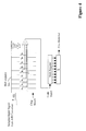
FIG. 1 is block diagram of an overview of a two-way ultrasonic positioning and navigation system 100 in accordance with one embodiment of the present invention. The system 100 includes a mobile platform P, and a number of beacons B0, B1, . . . , and BN−1, where N is an integer larger than one (i.e., at least two), and is preferably greater than two. The beacons B0, B1, . . . , and BN−1 may be placed at surveyed locations. Alternately, the beacons can be placed at arbitrary positions, which are automatically determined without user input during an initial system self-calibration procedure, described in more detail below. The system 100 performs two-way ultrasonic time-of-flight measurements to position or track the mobile platform P within a predetermined geographical range or service volume 101.
The number N of beacons B0, B1, . . . , and BN−1 should be adequate to provide accurate positioning of the mobile platform P throughout the geographical range 101. In a two-dimensional (2D) implementation, assuming the ultrasonic signal propagation speed is known, the minimum number of beacons necessary for the positioning or navigation of the mobile platform P is two. However, this may result in an ambiguity that is difficult to resolve. Hence, typically, the minimum number of beacons for a two-dimensional implementation is three when the beacons are placed in a non-collinear fashion. This idea is illustrated in FIG. 7. Similarly, for a three-dimensional (3D) positioning or navigation system, the minimum number of beacons necessary is three, again with a geometric ambiguity that may be difficult to resolved without additional knowledge or the use of a fourth (non-coplanar) beacon. In cases where the propagation speed of sound is not known precisely and is solved by using platform-to-beacon measurement results, the minimum number of beacons is four for 2D positioning/navigation systems, and is five for 3D positioning/navigation systems, respectively. In one embodiment of the present invention, beason-to-beacon measurements (as explained in more detail below) are used to calculate the speed of sound. The beacons are preferably at fixed locations so that changes in the inter-becon measurements are a consequence of the changes in the speed of sound in air. This measurements can be performed periodically (e.g. every 5 minutes) to update the speed of sound used by the positioning or navigation system.
Additionally, as a practical matter, in order to provide good accuracy one needs to ensure that the beacons are positioned to provide good geometry to facilitate an accurate position solution, increasing the requirements on the number of beacons. See Ray, P. K. and Mahajan, A., “Genetic Algorithms to obtain Optimal Location of Receivers in an Ultrasonic Position Estimation System,” Submitted to Robotics and Autonomous Systems, January 2001. Also, additional beacons may be included on top of the number deemed necessary for accuracy in order to provide system integrity and robustness against erroneous measurements or faulty equipment. If any of the beacons are not visible throughout the entire environment 101, more must be added to ensure that positioning accuracy is not degraded in any portions of the service volume 101.
FIG. 1A is a block diagram illustrating a first set of modules 110 of the system 100 in accordance with an embodiment of the present invention. The first set of modules 110 is preferably placed on the mobile platform (“platform”) P, and includes an ultrasonic array (“array”) 111 for transmitting and receiving ultrasonic signals. The first set of modules 110 also preferably includes an analog to digital signal converter (ADC) 112 coupled to the ultrasonic array 111 having one or more acoustic transducers or transceivers, a digital signal processor 113 coupled to the analog to digital converter 112, and a central processing unit (CPU) 114 coupled to the digital signal processor 113. The first set of modules further includes a memory unit 115 coupled to the CPU 114, and a user interface 116 also coupled to the CPU 114. When the system 100 is used to navigate the platform P, the first set of modules 110 further includes a vehicle odometry control and feedback sensor 117 a, and a field programmable gate array (or DSP) 118 coupled between the sensor 117 a and the CPU 114. The first set of modules 110 may further comprise a radio frequency data communication link 119 coupled to the digital signal processor 113 for communicating with the beacons using radio frequency signals, as explained in more detail below. The first set of modules 110 may further include augmentation navigation sensors 117 b, such as one or more gyroscopes and accelerometers, for obtaining information in order to accurately model the movement of the mobil platform P.
FIG. 1B is a block diagram illustrating a second set of modules 120 of the system 100 in accordance with an embodiment of the present invention. The second set of modules 120 is preferably placed on each of the N beacons B0, B1, . . . , and BN−1, and includes an ultrasonic array 121 having one or more acoustic transducers or transceivers for transmitting and receiving ultrasonic signals. The acoustic transducers or transceivers of the ultrasonic array 121 are coupled to a digital signal processor (DSP) 123 by an analog signal conditioning circuit 122. In an embodiment of the present invention where the speed of sound in air is determined by the system 100, as explained in more detail below, the second set of modules 120 further includes a temperature and/or relative humidity sensor 124 coupled to the DSP 123. The second set of modules 120 may further include a memory or data bank 128 and a radio frequency data communication link 129 also coupled to the digital signal processor 123 for communicating with the platform P and/or other beacons using radio frequency signals.
The analog signal conditioning circuit 112 or 122 converts digital signal into analog signals and conditions the resulting analog signal for transmission by the ultrasonic array 111 or 121, respectively. The analog signal conditioning circuit 112 or 122 also conditions and converts analog signals received from the ultrasonic array 111 or 121, respectively, into digital signals for processing by the DSP 113 or 123, respectively.
FIG. 1C is a block diagram illustrating the ultrasonic array 111 or 121 (of the mobile system 110 or a beacon 120) according to one embodiment of the present invention. The ultrasonic array 111 or 121 consists of one or more ultrasonic transducers. There may be separate transducers for transmission and reception, or the transducers can be operated as transceivers. In FIG. 1C, the ultrasonic array 111 or 121 includes four transceivers or transducer pairs, 1A, 1B, 2A and 2B, where 1A and 1B are placed back-to-back with each other, and 2A and 2B are placed back-to-back with each other and orthogonal to 1A and 1B, so that the four transducer pairs are facing four different horizontal directions. FIG. 1C only shows one of many possible configurations for the ultrasonic array 111 and 121, as the ultrasonic array 111 and 121 may include more or less transceivers or transducers that may be configured differently for different applications.
In many cases, an originator of an ultrasonic signal, which can be the platform or a beacon, does not possess knowledge of the relative direction of an intended recipient for the ultrasonic signal, and therefore does not know which transceiver or transducer to use to send the ultrasonic signal. One way of making sure that the ultrasonic signal will be received by the intended receipient is to broadcast out of all of the transducer pairs in the array 111 or 121. When transmitting from multiple transducers in an array simultaneously, care needs to be taken to ensure that sufficient transducer beam separation exists to avoid signal-cancellation effects. As a result, often more than one measurement cycles are required. In a preferred embodiment of the present invention, the ultrasonic signal is broadcast from transceiver pair 1A and 1B at one time, and then broadcast from transceiver 2A and 2B at a later time.
In some applications, the originator of the ultrasonic signal has rough knowledge about its location relative to the intended recipient array and thus will have knowledge of the optimal transducer(s) to transmit from in order to ensure successful link closure.
The transducers in the array 111 or 121 are coupled with the digital signal processor 113 or 123, through the analog signal conditioning circuits 112 or 122, respectively. The analog signal conditioning circuits 122 includes an analog to digital converter (ADC) 126 that converts any received signal to digital form for use by the digital signal processor 123. Circuits 122 also includes a digital to analog converter 127 for converting digital signals into analog signals to be sent to the transducer pairs in the ultrasonic array 121. Circuits 112 is configured similarly. The digital signal processor 113 or 123 is capable of controlling signal transmission and reception, including calculating signal arrival times and a figure-of-merit on the quality of each received signal. The digital signal processor 113 is further coupled to a CPU 114 that implements a positioning/navigation algorithm as described below.
FIG. 2 illustrates a 2-way time-of-flight measurement cycle 200 between an initiator and a respondent, according to one embodiment of the present invention. For ease of discussion, the initiator is assumed to be the platform P and the respondent is assumed to be one of the beacons, such as B0. However, only slight modification of the following discussion is needed if the initiator is one of the beacons and the respondent is the platform P or another beacon. In the 2-way time-of flight measurement cycle 200, as shown in FIG. 2, the platform P transmits at least one initiating ultrasonic signal 210 having a signal duration Ts at time 0. Commensurate with the transmission of the ultrasonic signal 210, the platform P starts a timer at time Tstart=Ts. Assuming the beacon B0 successfully receives the ultrasonic signal 210 at time Tp,or, the beacon B0 will, after a short fixed time delay Td, respond back to the platform P by transmitting at least one responding ultrasonic signal 220 toward the platform P. The responding ultrasonic signal 220 may have the same or a different signal duration as the initiating ultrasonic signal 210. When multiple distinguishable ultrasonic signals are received by the same beacon at approximately the same time, the beacon internally computes a figure-of-merit for each received signal, determines which received signal has the largest figure of merit, and responds only to the received signal with the largest internally calculated figure-of-merit. Determining a figure-of-merit is discussed in more detail below. In one embodiment of the present invention, the ultrasonic array 121 on the beacon B0 include multiple transceiver or transducer pairs, and one transceiver or transducer on the beacon will detect a signal before the others. The beacon B0 will respond back to only the first arrival of an initiating ultrasonic signal, to mitigate effects of signal multipath. A signal multipath is caused by the ultrasonic signal hitting another object(s) and being reflected from that object(s) to the beacon B0.
Assuming that the responding ultrasonic signal 220 is successfully detected at the platform P, the timer reading (TSTOP) at the signal time-of-arrival is noted. The two-way time-of-flight can be calculated by subtracting from TSTOP the fixed time delay, the signal duration(s) and other (known in advance) processing delays. The two-way time-of-flight measurements are converted to a distance between the platform and the beacon B0 by halving the two-way time-of-flight and multiplying the resulting time-of-flight by the speed of sound in air. Typically, the above process repeats, whereby the platform P will, in turn, communicate with each of the other beacons in-view. In a further embodiment of this invention, the platform may at times signal to multiple beacons, as explained in more detail below. In this case, special care is taken to ensure that the initiating or responding ultrasonic signals do not cause excessive self-interference (which would prevent successful signal receptions), either at any beacons B0, B1, . . . , and BN−1 or at the platform P.
The one-way time-of-flight measurement between the platform P and one of the beacons, such as B
0, located respectively at (x
0, y
0, z
0) and (x
r, y
r, z
r), is given by:
where c
or represents the average speed of sound along the path from the platform P to the beacon B
0 and d
or is the distance from the platform P to the beacon B
0. The above expression assumes a three-dimensional application. In cases where the platform and all of the beacons are located in the same plane or approximately the same plane, the third coordinate z can be disregarded. Similarly, the one-way time-of-flight measurement from the beacon B
0 to the platform P is given by:
where dro=dor if the platform P is stationary or slow-moving, i.e., its speed is much smaller than the speed of sound in air. In the above expression, cro represents the average speed of sound along the path from the beacon B0 to the platform P. The speed of sound in air can be calculated based readings from environmental sensors and known analytic expressions, or determined from the 2-way time-of-flight measurements 200 among beacons or between the platform and beacons, or a combination of both.
Wind effects on the speed of sound are made less significant by using the two-way ultrasonic positioning/
navigation system 100, as explained below. The speed of sound in air to a first-order approximation is given by the following expression:
as stated in the literature by H. Wehn and P. Belanger, “Ultrasound-Based Robot Position Estimation,” IEEE Transactions on Robotics and Estimation, Vol. 13, No. 5, October 1997. In the above equation, c is the speed of sound in the direction {right arrow over (e)} (which is a unit vector), T is the atmospheric temperature in Celsius,
{right arrow over (w)} is a wind velocity vector, and c
0 is the speed of sound at temperature 0° C. (which is approximately 331.45 m/s). If
is the magnitude of the wind velocity along {right arrow over (e)}, and
is the nominal speed of sound, then the speed of sound in the two opposite directions along {right arrow over (e)} are given by ĉ+v and ĉ−v, as illustrated in FIG.
3. The two respective one-way measurements should produce,
Thus, the timing error due to wind effects in a one-way system is proportional to v/ĉ, with the two one-way time-of-flight measurements in the
system 100,
where the term O ((v/ĉ)2) represents the timing error resulting from the wind effects and it signifies that the error is proportional to (v/ĉ)2. Thus, the timing error in the two-way system 100 is proportional to (v/ĉ)2. Because, under normal conditions, v<<ĉ, the two-way paradigm, represents a significant improvement in positioning accuracy and hence provide the foundation for an improved ranging and positioning system. An example illustrating this advantage is as follows:
ĉ=331.45 m/s (nominal sound speed, neglecting wind)
v=10 m/s (magnitude of wind velocity along path)
d=20 m (actual distance)
Clearly, the two-way measured distance d+− is more accurate than either the one-way measured distance d+ along the blow of the wind or one-way measured distance d− against the blow of the wind. This example assumes that the platform P remains stationary or is slow moving during the two-way measurement cycle, so that the geometry between the beacon and the platform remains roughly constant over a fraction of a second in practical applications to make this approach effective. For faster moving mobil platforms, the movement during the measurement cycle needs to be modeled as part of the navigation algorithm.
In one embodiment of the present invention, the system 100 includes multiple beacons, and each ultrasonic signal has only one intended recipient. In order to facilitate this mode of operation, the ultrasonic signals are coded using, for example, signal modulation. At least one unique code is associated with each beacon and, in some cases, with the platform itself. Well-known modulation techniques include frequency shift keying, phase shift keying or pulse positioning (on-off keying). The ultrasonic transducers/transceivers and associated tuning circuitry are configured to provide adequate bandwidth to support the signal design. In a preferred embodiment, the ultrasonic signal is coded with information using binary phase shift keying (BPSK). In particular, two basis functions are defined as:
s 1(t)=cos(ωt) 0≦t≦T c
s 2(t)=cos(ωt+π)=−s 1(t)
Because of the antipodal relationship between these two functions, only a single basis function is necessary in practice. The form of the transmitted signal is:
Thus, the total pulse duration is the product NT
c, where N is the length of the binary sequence {g
p} and T
c is the duration of each chip (i.e., each item in the binary sequence). In the above expression, the sequence {g
p} is chosen to provide good signal correlation properties as is well known to those skilled in the art of signal processing. As an example, Gold Codes of
length 127 have been utilized for this purpose. These codes provide good autocorrelation properties for time-of-flight detection as well as low cross-correlations among different signal sequences, and facilitate unique identification of signal recipients. A sampled matched filter has been implemented in the analog signal conditioning circuits
112/
122 for the purposes of real-time signal detection. The output value of the matched filter is compared to a threshold to detect signal arrival and the precise time-of-arrival is computed by finding a local maximum value of the matched filter output over a short interval following the initial threshold crossing. Also, the maximum value of the corresponding matched filter can be used as a signal detection figure-of-merit for descriminating between simultaneous arrivals (in different array faces) and/or computing an expected measurement error. Mathematically, the resulting signal form the sampled matched filter is:
where,
m=1, 2, 3, . . .
Δt=sample time interval
Nc=# samples per chip=Tc/Δt
r[m]=sampled received signal=r((m−1)Δt), r(t)=0 for t<0
c[k]=cos(ω(k−1)Δt)
z[m]=sampled matched filter output at t=(m−1)Δt.
A block diagram illustrating a correlator circuit for detecting an input signal is shown in FIG.
4. If no gain control is utilized in the analog/digital converter
112/
122 or the signal is not hard-limited, the amplitude of the matched filter output may scale with the amplitude of the received signal. To mitigate this effect, the algorithm can be slightly modified to normalize the matched filter output by the autocorrelations of the received and ideal signals,
The number of identification codes assigned to each ultrasonic array 111 or 121 depends on the number and orientation of the transducers in the array, and more generally on the array architecture and how the transducers are used. In one embodiment, each array 111 or 121 includes four faces each having a transducer pair (see FIG. 1C). Transmitted ultrasonic beam patterns from neighboring faces overlap, and two distinct device identification codes are associated with each ultrasonic array (beacon or the platform). Each transmitted signal specifies via the code the intended recipient so that each ultrasonic array listens for only those codes unique to itself. When responding to a detected signal, the array will in turn respond back with a corresponding code, also unique to itself. The use of unique codes helps avoid false detections. In another embodiment of this invention, the intended recipient of a transmitted signal are communicated using a RF signal accompanying the ultrasonic signal.
Because the transmitted ultrasonic beam patterns of neighboring transducers overlap, simultaneous transmission from adjacent transducers is not preferred due to possible signal cancellation effects resulting from differences in signal phases. Thus, only transducers on opposing faces of the ultrasonic array (or a “transmitting pair”)are allowed to transmit simultaneously. Each pair of opposing transducers in a ultrasonic array is assigned a distinct code, and at least two distinct codes are assigned to each ultrasonic array to allow for the identification of each of the two transducer pairs of the array. At the initiator of a measurement cycle, typically no information is available to the initiator concerning which face (or face-pair) is optimally aligned with a desired recipient, and therefore the initiator transmits a sequence of signals from each transmitting pair of the initiator's ultrasonic array. Furthermore, each signal in the sequence of transmitted signals is encoded with a different one of the identification codes associated with the intended recipient. In some cases, each signal may also include the code associated with the transmitting pair that transmits the signal. The intended recipient responds only to a first reception of a coded signal that is above the detection threshold to minimize the effect of multipath transmission of the transmitted signals, because in many cases it is possible for a multipath signal to possess larger signal energy than the direct path signal. By processing only the first coded signal to be received that is above the detection threshold, the system ignores (and thus effectively filters out) multipath signals that travel by indirect paths from the transmitting device to the recipient device.
At the recipient, receive channels from different array faces are processed independently but in parallel. When multiple signals arrive closely in time, the device responds to the signal received from the face having the best reception (e.g., the face with the largest correlation value or figure of merit).
In one embodiment of the present invention, the platform P polls the beacons B0, B1, . . . , and BN in turn to determine its position with respect to the beacons B0, B1, . . . , and BN−1. A polling scheme involving a platform P and three beacons B0, B1, and B2 according to one embodiment of the present invention is illustrated in FIG. 5. In this polling scheme, each beacon is signaled twice in succession from the two transmitting pairs in the array 111 positioned on the platform P. As shown in FIG. 5, the platform P transmits (“TX:C0”), from transmitting pair 1A, 1B, an initiating ultrasonic signal with signal code C0 identifying beacon B0. This signal is received and recognized (“RX:C0”) by beacon B0, and in response, beacon B0 transmits a responding ultrasonic signal coded with signal code C2 after a predetermined time delay from receiving the signal C0, as illustrated in FIG. 2. The responding ultrasonic signal C2 is preferably transmitted from the same transceiver of the array 121 that received the signal C0. This signal is received and recognized by the platform P (“RX:C2”). Shortly thereafter, the platform P transmits, from transmitting pair 2A, 2B, another initiating ultrasonic signal with signal code C1 also identifying beacon B0. The signal C1 is also received and recognized by the beacon B0, and in response, beacon B0 transmits another responding ultrasonic signal coded C3 after the predetermined time delay from receiving the signal C1, as illustrated in FIG. 2. The responding signal C3 is preferably transmitted from the same transceiver or transducer pair of the array 121 that received the signal C1. This signal is received and recognized by the platform P (“RX:C3”).
The platform P continues to poll the other beacons using the same process. Some signals may not be received by the intended recipient. For example, as shown in FIG. 5, the platform P transmits an initiating ultrasonic signal with signal code C4 identifying beacon B1. This signal, which is transmitted by transmitting pair 1A, 1B, is not received by beacon B1. The platform P then transmits another initiating ultrasonic signal with signal code C5 also identifying beacon B1, this time from transmitting pairs 2A and 2B. The signal C5 is received and recognized by the beacon B1(“RX:C5”), and in response, beacon B1 transmits a responding ultrasonic signal coded C7 after the predetermined time delay from receiving the signal C5, as illustrated in FIG. 2. The responding signal C7 is preferably transmitted from the same transceiver or transducer pair of the array 121 that received the signal C5. This signal is received and recognized by the platform P (“RX:C7”).
Still referring to FIG. 5, the platform P continues to transmit an initiating ultrasonic signal with signal code C8 identifying beacon B2. The ultrasonic signal with signal code C8 is transmitted by platform P from transmitting pair 1A, 1B. This signal is received and recognized (“RX:C8”) by beacon B2, and in response, beacon B2 transmits a responding ultrasonic signal coded with signal code C10 after a predetermined time delay from receiving the signal C8, as illustrated in FIG. 2. The responding signal C10 is preferably transmitted from the same transceiver or transducer pair of the array 121 that received the signal C8. This signal is received and recognized by the platform P (“RX:C10”). Shortly thereafter, the platform P transmits from transmitting pair 2A, 2B another initiating ultrasonic signal with signal code C9 also identifying beacon B2. The signal C9 is also received and recognized by the beacon B2, and in response, beacon B2 transmits another responding ultrasonic signal coded C11 after the predetermined time delay from receiving the signal C9, as illustrated in FIG. 2. The responding signal C11 is preferably transmitted from the same transceiver of the array 121 that received the signal C9. In the example shown in FIG. 5, this signal is not received by the platform P. There are many reasons why a signal may not be received by the intended recipient, including insufficient transmission amplitude, insufficient signal sensitivity at the recipient, multipath or noise.
In an alternative embodiment of the present invention, the system 100 includes radio frequency (RF) devices establishing an RF data communication link 119/129 between the platform and each beacon and/or among the beacons. The RF link provides an independent data communication channel between the platform and beacons (and/or beacon-to-beacon). The identification of a recipient for an ultrasonic signal can be communicated using the radio frequency data communication link 119/129 rather than by the encoding of the ultrasonic signal itself. One way of using the RF link to identify a recipient of a transmitted ultrasonic signal is to transmit an RF trigger signal identifying the recipient together with the ultrasonic signal. The recipient, upon receiving the ultrasonic signal, also transmits an RF acknowledge signal to indicate that the ultrasonic signal is successfully received. Because the RF signals travel at the speed of light (roughly 3 orders of magnitude faster than the speed of sound in air), they arrive at the recipient essentially instantaneously relative to the accompanying ultrasonic signals.
FIGS. 6A and 6B illustrate a polling scheme using the RF link 119/129 for a system 100 having one platform P and four beacons B0, B1, B2, and B4. In this example, it is assumed that the initiator does not possess knowledge of what transducer face in its array 111/121 is most optimal for transmission, so that each recipient is signaled twice in succession, as in the previous scheme with the RF link unavailable. As shown in FIGS. 6A and 6B, the platform P transmits (“TX”) an initiating ultrasonic signal C0 from transmitting pair 1A and 1B of the array 111. At approximately the same time, the platform P also transmits through the RF link 119 either one RF trigger signal (“RFT”) identifying both beacon B0 and beacon B2 as the recipients for the ultrasonic signal C0, or two RF trigger signals, one identifying beacon B0 and another identifying beacon B2. The RFT identifying beacon B2 is received at beacon B2, triggering B2 to accept the ultrasonic signal C0 that arrives shortly after. After a predetermined delay, the beacon B2 transmits a responding ultrasonic signal C6 from the same transceiver in the array 121 that received the ultrasonic signal C0. At approximately the same time, the beacon B2 also transmits through the RF link 129 an RF acknowledge signal (“RFA”) identifying the beacon B2 as the initiator and the platform P as the recipient for the ultrasonic signal C6.
The RFT identifying B0 is received at the beacon B0, triggering B0 to accept the ultrasonic signal C0 that arrives shortly after the RFT. After a predetermined delay, the beacon B0 transmits a responding ultrasonic signal C2 from the same transceiver in the array 121 positioned on the beacon B0 that received the ultrasonic signal C0. At approximately the same time, the beacon B0 also transmits through the RF link 129 an RF acknowledge signal (“RFA”) identifying the beacon B0 as the initiator and the platform P as the recipient for the ultrasonic signal C2. The responding ultrasonic signal arrives at the platform P shortly after the corresponding RFA arrives at the platform. Since the RFA from B2 is received before the RFA from B0 is received, the platform knows that the signal C6 is from B2 and the signal C2 is from B0 because C6 is received before C0.
As illustrated in FIGS. 6A and 6B, this process is repeated again for beacons B0 and B2, except that this time, the initiating ultrasonic signal C1 is transmitted from the transmitting pair 2A and 2B. Next, the platform goes ahead to poll the other two beacons also twice, once by transmitting the initiating ultrasonic signals from transmitting pairs 1A and 1B, and once from transmitting pairs 2A and 2B. In the example shown in FIG. 6A, some of these signals are not received at the intended recipients (e.g., because of the direction of transmission or signal strength of the transmitted signals).
In addition to providing identification of the initiator and/or the recipient(s) for a respective transmission, the trigger message may also provide information regarding additional fixed turn-around delays that are unique to each recipient. In some implementations, the “fixed” turn-around delay of each distinct beacon is adjustable or programmable, enabling the system to adjust the turn-around delays so as to minimize the probability of overlapping signal returns. Overlapping signal returns are highly undesirable because they result in increased receiver noise and may also prohibit successful signal detection back at the initiator. Simultaneous (or nearly simultaneous) signaling to multiple recipients is feasible in cases where a priori knowledge of expected time-of-flight is available, which is often the case shortly after system startup, when the positioning or navigation system 100 has reached steady state performance, and the approximate relative positions of the platform and the beacons have already been determined.
Another use of the RF link is to add a power-saving feature to the system 100, whereby the beacons can be remotely switched to a low-power sleep mode when the system 100 is not operational.
Although some signals are not received by their intended recipients, in many cases (with or without the RF link), both polling trials targeted at the same beacon result in signal detection at the beacon(s) and the platform. Frequently, when both attempts to signal a particular intended recipient are successful, one of the two resulting distance measurements between the platform and beacon is possibly erroneous due to signal multipath. Normally, the erroneous measurement corresponds to a longer path and hence a longer time-of-flight and is therefore easy to recognize. The positioning or navigation algorithm in the system 100 detects and ignores these erroneous measurements. More specifically, the system is configured to use only the shorter of the two measurements in cases where both two-way measurements are successful. This procedure can be optimized when the optimal face to transmit from is known. Depending on the array design and accuracy requirements, it may also be necessary to take into consideration the geometric difference between the transducer face centers and the reference position of the respective beacon (typically the center of the array head).
In a further embodiment of this invention, the CPU 114 may be distributed between the system 100 and a remote station, where data is communicated between the platform and the remote station using radio frequency devices. In one version of this embodiment, the initializing ultrasonic signals are sent from the beacons, with the platform responding to the beacons by sending a responding ultrasonic signal for each received initializing ultrasonic signal. The beacons transmit the resulting distance measurements to the remote station, which in turn computes the location of the platform. The resulting location information is then sent to the platform for use in navigation of the platform.
In one embodiment of the present invention, the coordinate frame for the platform P is a local coordinate system tied to the beacon locations, rather than an absolute coordinate frame tied to an external reference (such as absolute latitude and longitude). Algorithms for trilateration or tracking (e.g. Kalman Filtering) well known to those in the art are used to solve for the position of the platform. The equations to be solved are inherently nonlinear. One algorithm for positioning of a static platform can be found in an article by Figueroa, F. and Mahajan, A., “A Robust Navigation System for Autonomous Vehicles using Ultrasonics,”
Control Engineering Practice, Vol. 2, No. 1, pp. 49-54, February, 1992. This algorithm includes the speed of sound as an unknown to be solved for by using the time-of-flight measurements. In matrix form,
where:
tofi=two-way time-of-flight to ith beacon, where i=0, 1, . . . , N−1;
(xi, yi, zi)=coordinates of the ith beacon;
ri=xi 2+yi 2+zi 2;
(u, v, w)=coordinates of the platform P;
c=speed of sound; and
p=ui 2+vi 2+wi 2.
The above formulation is sub-optimal due to the fact that it contains a redundant unknown (p), but is nonetheless simple, which is easily solved as long as at least 5 measurements from five different beacons are available and geometric singularity conditions, such as all beacons lying in a same plane for 3D implementation or on a same line for 2D implementation, are avoided. This model assumes that the measurements are taken while the platform is stationary or slow moving, the average speed of sound is constant amongst the various lines-of-sight, and measurement biases (e.g., the fixed time delays at the recipient devices) have been removed from the time-of-flight values.
Alternatively, a common approach to positioning a static or slow-moving platform involves an iterative least-squares adjustment resulting from linearizing a nonlinear set of equations, as in the following
where an initial approximate position (u, v, w) of the platform P is assumed to be known. The idea is to successively compute improved estimates of the platform position (u+Δu,v+Δv,w+Δw) and the speed of sound c+Δc, using the following set of equations:
is the ith measurement residual, i=0, 1, . . . , n−1, where c is the current approximate speed of sound estimate, which can be calculated initially based on current temperature and possible relative humidity readings, and n is the number of beacons for which measurements are available;
Δ{right arrow over (m)}=(Δm0 Δm1 . . . Δmn−1)T is a vector of measurement residuals;
(u, v, w)T is the current platform position estimate;
(Δu, Δv, Δw)T is the platform position differential correction;
Δc is the speed of sound differential correction;
Δ{right arrow over (x)}=(Δu Δv Δw Δc)
T is a vector of the unknowns; and
is a matrix of measurement partial derivatives.
A weighted least-squares solution to the above Equation (2) is given by
Δ{right arrow over (x)}=(A T WA) A T W{right arrow over (r)}
where {right arrow over (r)}=({right arrow over (r)}1 {right arrow over (r)}2 . . . {right arrow over (r)}n), and W is a weighting matrix having diagonal elements σ0 2 σ1 2 . . . θn−1 2 with all other elements being zero, where σi 2 is an error variance for the ith measurement. The error variance represents the uncertainty of the measurement and is assumed known in advance. In cases where the measurement variance is not known, W may be taken to identity (i.e. all σi 2 equal to one), resulting in an unweighted solution. The improved estimates of platform position and speed of sound scaling factor are computed as described and provides the maximum likelihood estimate of these parameters. The procedure can be iterated (i.e., take the improved estimate of (u+Δu,v+Δv,w+Δw) as the new approximate position and repeat) until sufficient convergence (or divergence in a pathological case) is detected. An advantage of the iterative techniques using equation (2) over the former linear method of equation (1) is that the iterative method tends to provide more accurate position and speed of sound estimates. However, this iterative approach requires an approximate initial position and speed of sound for convergence. In some cases, such estimates may be unavailable and Equation (1) can be solved first to provide this initial estimate for subsequent iteration using Equation (2).
In an alternative embodiment of the invention, the speed of sound is assumed known. For example, the speed of sound may be computed from environmental readings or from inter-beacon measurements. In this case, the unknowns are only the platform position coordinates (u, v, w). Accordingly, the row dimension of Equations (1) or (2) is reduced by one.
In order to accurately utilize ultrasonic time-of-flight measurements when the platform is mobile, it is necessary that the platform either moves very slowly, so that movement during each measurement epoch can be ignored, [See C.—C. Tsai, “A Localization System of a Mobile Robot by Fusing Dead-Reckoning and Ultrasonic Measurements”, IEEE Transactions on Instrumentation and Measurement, Vol. 47, No. 5, October 1998], or the movement of the platform during each measurement epoch is accurately modeled. The “movement modeling” requirement relates to the fact that the speed of sound in air is slow enough that in some situations platform movement during the time the signal travels from the beacon to the platform (and/or platform to beacon) can be significant. Therefore,
system 100, when used in navigation applications involving wheeled mobile platforms, further includes a vehicle odometry control/
feedback sensor 117 a, and a field programmable gate array (or DSP)
118 coupled between the
sensor 117 a and the
CPU 114. The
system 100 may further include additional navigation sensors for improved accuracy, such as gyroscope(s) and accelerometer(s)
117 b. These components provide a measure (or permits estimation) of translation and rotation of the platform P during the measurement cycle. The measurement model within the tracking algorithm is then augmented appropriately, such as,
where(uTX, vTX, wTX)T and (uRX, vRX, wRX)T are the positions of the platform at the time of transmission to the ith beacon and the time of reception from the ith beacon, respectively. The platform positions (uTX, vTX, wTX)T and (uRX, vRX, wRX)T may be related to the platform position at the time the measurement is incorporated using either measurements or estimates of vehicle orientation and velocity. Care must be taken to ensure that adequate computational consistency of coordinate frames (body frame, earth-referenced inertial frame and beacon-relative frame, etc.) is maintained when integrating sensors in a local navigation system.
FIG. 8 is a navigation data flow diagram for a navigation system using the two-way ultrasonic positioning techniques of the present invention. Navigation algorithms for tracking mobile platforms are well known. See for example L. Kleeman, “Optimal estimation of position and heading for mobile robots using ultrasonic beacons and dead-reckoning”, IEEE International Conference on Robotics and Automation, Nice, France, pp 2582-2587, May 10-15 1992 and J. J. Leonard and H. F. Durrant-Whyte. Mobile robot localization by tracking geometric beacons. IEEE Trans. Robotics and Automation, 7(3): 376-382, June 1991.
The positioning and navigation algorithms discussed above assume that the ultrasonic array on the platform array is located at a position reference point corresponding to the platform coordinates. If this is not the case, the measurement equations should be modified to include the body frame transformation from the ultrasonic array to the positioning reference point (e.g. from an array antenna on the top of a wheeled mobile robot to the center of its axle). This transformation requires knowledge of vehicle orientation, and the navigation-tracking algorithm includes estimation of the necessary parameters (e.g. vehicle heading in a 2D application).
Furthermore, it is understood that in practice erroneous measurements are likely to occur, such as those due to hardware anomalies and multipath. As a result, successful implementation of the described positioning and navigation algorithms should include some form of statistical outlier testing to detect and eliminate these erroneous measurements. Such tests are well known to those in the art and include externally Studentized residual tests and Kalman Filter innovations tests.
In a further embodiment of the present invention, inter-platform measurements and/or environmental readings such as temperature and possibly relative humidity readings are used to further enhance the speed of sound calculation. In the case that the speed of sound is not expected to vary spatially, (i.e. no large temperature gradients along the signal path), its average value can be modeled as a time-varying random constant. So at any given instant in time, the speed of sound in air is assumed constant throughout the service volume, but is expected to vary (slowly) in time. The variation can be computed from temperature/environmental readings or estimated based on, for example, platform-beacon or inter-beacon measurements. For the case that the system is self-calibrating, as explained in more detail below, the speed of sound during calibration is fixed using temperature and possibly relative humidity readings, but is solved for during subsequent operation. In one embodiment, the beacons are configured to periodically signal each other to measure the time-of-flight between the various beacon pairs. This information is then used to compute the current speed of sound. Since the inter-beacon distances are fixed, speed of sound computations based on inter-beacon time-of-flight measurements are typically very accurate.
In another embodiment, temperature and/or humidity sensors are incorporated into the platform and/or each of the beacons. The CPU in the platform or in a remote device receives the temperature information from all the beacons and the platform, and uses the temperature information to construct a spatially varying sound speed-scaling map. One approach is to compute a temperature dependent factor at each device (platform and beacon),
where T
k is the temperature in Celsius at the k
ith device. A modified measurement model is then used to compensate for spacial sound speed changes,
where c represents an (overall) average sound speed value. The above model assumes that temperature changes linearly along the path, which is likely violated in any real environment. However, the error in making this approximation is small enough in many operating environments.
To eliminate the need for manual survey equipment for determining the positions of the beacons, the system can be self-calibrating. Typically self-calibration is only done once at initial installation, before training and using the system 100, unless the system 100 is later reconfigured. The self-calibration procedure determines the location of the beacons in a single local coordinate system. The self-calibration procedure of a local navigation system is simplified when all beacons are capable of ranging to each other. One approach to the self-calibration problem (for a two-dimensional case) can be found in E. LeMaster and S. Rock, Self-Calibration of Pseudolite Arrays Using Self-Differencing Transceivers, Institute of Navigation GPS-99 Conference, Nashville, Tenn., September 1999, which discusses a radio-frequency based ranging system using GPS-like signals.
In one embodiment of the present invention, inter-beacon measurements are used collectively to construct a relative coordinate system for subsequent positioning or navigation. First, all possible inter-beacon measurements are taken. Successful inter-beacon measurements require that the two beacons participating in a measurement cycle 200 possess line-of-sight visibility and are within range of one-another. Improved accuracy is expected incorporates platform-beacon measurements from various locations in the service volume are incorporated. Note that the self-calibration discussion that follows assumes a 2D implementation. Extensions to 3D require only slight modification of these procedures. Also, the discussion assumes that the measurements are in terms of distance rather than time-or-flight, so that the conversion of signal time-of-flight to distance has already been completed.
Given only the distances between the beacons, the solution for the locations or coordinates of the beacons in a coordinate frame is not unique unless the arrangement of the beacons is constrained in some way. In one embodiment of the present invention, the N beacons B0, B1, . . . , BN−1 are first placed at various fixed locations throughout the service volume subject to the following constraints:
(1) The first 3 beacons B0, B1, and B2 installed should be capable of measuring to each other and be in an arrangement that is not close to collinear (i.e. the first three beacons are within range and possess line-of-sight of each other, and not lying on or near a single line). Moreover, the arrangement of B0-B1-B2 should be counterclockwise (i.e., if one is standing at beacon B0 and looking toward B1, B2 should lie on the left).
(2) Additional beacons B3, B4, . . . , BN−1 are installed such that any beacon Bk has visibility to at least 3 other beacons of the set B0, B1, . . . , Bk−1 that are themselves not close to a collinear arrangement.
(3) Enough beacons are installed to provide adequate solution geometry throughout the service volume, preferably with redundancy for system robustness. In one embodiment of the present invention, the number of beacons is at least 4.
FIG. 9 illustrate a self-calibration procedure 900, according to one embodiment of the present invention. The self-calibration procedure 900 involves an iterative adjustment, requiring an initial condition that is subsequently improved with iteration. In one embodiment of the present invention, after the beacons are placed subject to the above constraint (step 910) and the inter-beacon measurements are done to determine a set of inter-beacon distances (step 920), B0 is initially fixed as the origin of a coordinate frame for the system 100 (step 930), or B0 has coordinates (0,0) in a 2D implementation. The direction from B0 to B1 initially defines the x-axis of the coordinate system (step 940). Therefore, B1 initially has coordinates (d01, 0), where d01 is the distance between beacons B0 and B1, as determined by the inter-beacon measurements between the two beacons. The initial location of beacon B2 is then determined by the law of cosines (step 950), i.e., B2=(x2, Y2),
where
with d02 and d12 being the measured distances between B2 and, respectively, B0 and B1. The y-coordinate of beacon B2 is assumed positive due to the restriction that the beacon arrangement B0-B1-B2 are counterclockwise. The coordinates of all other beacons are determined likewise (step 960). For example, the coordinates of beacon Bk is determined after the locations of the beacons B0, B1, . . . , Bk−1 are known.
Having determined the initial locations of the beacons, the exact locations of the beacons are iteratively improved (step
970). In one embodiment of the present invention, the Moore-Penrose pseudo-inverse method is used in the iteration process as described below. Each individual distance measurement d
ij represents the distance between two beacons B
i and B
j, such that
The available measurements M are collected and arranged in vector form. The beacon coordinates are also arranged in a state vector having 2N elements:
and the correction to the beacon coordinates are arranged in a state correction vector
The matrix equation for the coordinates correction is
Δ{right arrow over (d)}=AΔ{right arrow over (x)},
where Δ{right arrow over (d)} is a vector of M measurement residuals,
and the kth row of the M by 2N matrix A has only four non-zero elements,
So the matrix A has a rank of at most 2N−3 and is sparse, with relatively few non-zero elements. The state correction Δ{right arrow over (x)} is calculated as
Δ{right arrow over (x)}=A+Δ{right arrow over (d)},
where A+ is the Moore-Penrose pseudo-inverse of A. Efficient methods of computing the Moore-Penrose pseudo-inverse of a sparse matrix are well known to those in the art of numerical analysis. The iteration can be continued until sufficient convergence is detected (e.g., by monitoring the norm of the state correction ∥Δ{right arrow over (x)}∥), or until divergence is detected in the pathological case (e.g. too many iterations as a result of not enough valid measurements). The method automatically compensates for the fact that the matrix equation is rank-deficient.
In an alternative embodiment of the present invention, platform-beacon measurements are taken at various locations throughout the service volume for improved accuracy. In this case, the vector of unknowns expands to include the coordinates of the platform at each of these locations where the measurements are taken. In yet other embodiments of the present invention, geometrical and/or statistical tests are included to help eliminate erroneous measurements expected in practice.
Overall, the self-calibration procedure as discussed above is relatively straightforward, except that special care must be taken to resolve ambiguities and geometrical singularities (or poor conditioning) that can arise in practice. Also, convergence difficulties can arise if a poor initial condition is chosen, due to the nonlinear nature of the problem. The accuracy with which the beacon coordinates are known or calculated limits the overall positioning accuracy of the platform during operation of the system. A self-calibrating system is inherently less accurate than a system in which the beacon locations are accurately surveyed. Two factors that limit the accuracy of the self-calibration, and which can result in “dilution of precision” of platform position measurements, are the relative geometry of the beacons and the accuracy of the ranging measurements. It is the responsibility of the system installer (e.g., the user) to ensure that the system enjoys “good geometry,” by placing sufficiently many beacons in the environment at favorable locations. For instance, the beacons should be placed at locations so that the mobile platform not only has a direct signaling path to at least four beacons at all positions within the allowed range of platform positions, but also the directions of the signal paths between the platform and the four beacons must be separated by at least a specified minimum angle (e.g., 20 degrees) at all possible platform locations. If it is not possible to meet these requirements using only four beacons, then the system should include one or more additional beacons so that there are always four beacons among the set of beacons in the system that meet these requirements for all possible positions of the mobile platform.
Other important factors affecting the resulting positioning or navigation accuracy include unknown platform characteristics and unknown local temperature and possibly relative humidity conditions, which result in uncertainty in the measurement model, including uncertainty in determining the local speed of sound and uncalibrated body frame biases. Signal processing errors and uncertainties concerning signal propagation time through the circuitry in the platform and beacons also reduce the accuracy of the self-calibration process and determination of the platform position. To the extent that the accuracy of the positioning system depends on the use of augmenting sensors, such as gyroscopes, accelerometers and wheel sensors, for determining the direction and speed of movement of the mobile platform, the accuracy of such sensors may limit the accuracy of the positioning system. Wheel slippage on the mobile platform, due to environmental conditions, may also reduce positioning accuracy.