US6674060B2 - Method and apparatus for illuminating an object with white light - Google Patents
Method and apparatus for illuminating an object with white light Download PDFInfo
- Publication number
- US6674060B2 US6674060B2 US09/985,729 US98572901A US6674060B2 US 6674060 B2 US6674060 B2 US 6674060B2 US 98572901 A US98572901 A US 98572901A US 6674060 B2 US6674060 B2 US 6674060B2
- Authority
- US
- United States
- Prior art keywords
- light
- luminous power
- illumination
- colour
- measuring
- Prior art date
- Legal status (The legal status is an assumption and is not a legal conclusion. Google has not performed a legal analysis and makes no representation as to the accuracy of the status listed.)
- Expired - Lifetime, expires
Links
- 238000000034 method Methods 0.000 title claims abstract description 30
- 238000005286 illumination Methods 0.000 claims abstract description 113
- 239000003086 colorant Substances 0.000 claims abstract description 18
- 238000005259 measurement Methods 0.000 claims description 56
- 230000000007 visual effect Effects 0.000 claims description 5
- 238000004519 manufacturing process Methods 0.000 claims description 3
- 238000010586 diagram Methods 0.000 description 10
- 239000004973 liquid crystal related substance Substances 0.000 description 10
- 238000001914 filtration Methods 0.000 description 7
- 230000015654 memory Effects 0.000 description 5
- 230000035945 sensitivity Effects 0.000 description 3
- 238000004364 calculation method Methods 0.000 description 2
- 230000003247 decreasing effect Effects 0.000 description 2
- 238000005265 energy consumption Methods 0.000 description 2
- 230000010355 oscillation Effects 0.000 description 2
- OAICVXFJPJFONN-UHFFFAOYSA-N Phosphorus Chemical compound [P] OAICVXFJPJFONN-UHFFFAOYSA-N 0.000 description 1
- 230000032683 aging Effects 0.000 description 1
- 239000011248 coating agent Substances 0.000 description 1
- 238000000576 coating method Methods 0.000 description 1
- 239000004020 conductor Substances 0.000 description 1
- 230000007423 decrease Effects 0.000 description 1
- 230000001419 dependent effect Effects 0.000 description 1
- BHEPBYXIRTUNPN-UHFFFAOYSA-N hydridophosphorus(.) (triplet) Chemical compound [PH] BHEPBYXIRTUNPN-UHFFFAOYSA-N 0.000 description 1
- 238000012804 iterative process Methods 0.000 description 1
- 230000008447 perception Effects 0.000 description 1
- 230000004044 response Effects 0.000 description 1
- 230000035807 sensation Effects 0.000 description 1
- 238000004088 simulation Methods 0.000 description 1
- 230000003595 spectral effect Effects 0.000 description 1
- 238000001228 spectrum Methods 0.000 description 1
- 230000003019 stabilising effect Effects 0.000 description 1
- 230000001131 transforming effect Effects 0.000 description 1
- 230000003936 working memory Effects 0.000 description 1
Images


Classifications
-
- G—PHYSICS
- G09—EDUCATION; CRYPTOGRAPHY; DISPLAY; ADVERTISING; SEALS
- G09G—ARRANGEMENTS OR CIRCUITS FOR CONTROL OF INDICATING DEVICES USING STATIC MEANS TO PRESENT VARIABLE INFORMATION
- G09G3/00—Control arrangements or circuits, of interest only in connection with visual indicators other than cathode-ray tubes
- G09G3/20—Control arrangements or circuits, of interest only in connection with visual indicators other than cathode-ray tubes for presentation of an assembly of a number of characters, e.g. a page, by composing the assembly by combination of individual elements arranged in a matrix no fixed position being assigned to or needed to be assigned to the individual characters or partial characters
- G09G3/34—Control arrangements or circuits, of interest only in connection with visual indicators other than cathode-ray tubes for presentation of an assembly of a number of characters, e.g. a page, by composing the assembly by combination of individual elements arranged in a matrix no fixed position being assigned to or needed to be assigned to the individual characters or partial characters by control of light from an independent source
- G09G3/3406—Control of illumination source
- G09G3/3413—Details of control of colour illumination sources
-
- H—ELECTRICITY
- H04—ELECTRIC COMMUNICATION TECHNIQUE
- H04N—PICTORIAL COMMUNICATION, e.g. TELEVISION
- H04N17/00—Diagnosis, testing or measuring for television systems or their details
- H04N17/04—Diagnosis, testing or measuring for television systems or their details for receivers
-
- H—ELECTRICITY
- H04—ELECTRIC COMMUNICATION TECHNIQUE
- H04N—PICTORIAL COMMUNICATION, e.g. TELEVISION
- H04N9/00—Details of colour television systems
- H04N9/64—Circuits for processing colour signals
- H04N9/73—Colour balance circuits, e.g. white balance circuits or colour temperature control
-
- H—ELECTRICITY
- H05—ELECTRIC TECHNIQUES NOT OTHERWISE PROVIDED FOR
- H05B—ELECTRIC HEATING; ELECTRIC LIGHT SOURCES NOT OTHERWISE PROVIDED FOR; CIRCUIT ARRANGEMENTS FOR ELECTRIC LIGHT SOURCES, IN GENERAL
- H05B45/00—Circuit arrangements for operating light-emitting diodes [LED]
- H05B45/20—Controlling the colour of the light
- H05B45/22—Controlling the colour of the light using optical feedback
-
- G—PHYSICS
- G09—EDUCATION; CRYPTOGRAPHY; DISPLAY; ADVERTISING; SEALS
- G09G—ARRANGEMENTS OR CIRCUITS FOR CONTROL OF INDICATING DEVICES USING STATIC MEANS TO PRESENT VARIABLE INFORMATION
- G09G2320/00—Control of display operating conditions
- G09G2320/06—Adjustment of display parameters
- G09G2320/0626—Adjustment of display parameters for control of overall brightness
- G09G2320/0633—Adjustment of display parameters for control of overall brightness by amplitude modulation of the brightness of the illumination source
-
- G—PHYSICS
- G09—EDUCATION; CRYPTOGRAPHY; DISPLAY; ADVERTISING; SEALS
- G09G—ARRANGEMENTS OR CIRCUITS FOR CONTROL OF INDICATING DEVICES USING STATIC MEANS TO PRESENT VARIABLE INFORMATION
- G09G2320/00—Control of display operating conditions
- G09G2320/06—Adjustment of display parameters
- G09G2320/0626—Adjustment of display parameters for control of overall brightness
- G09G2320/064—Adjustment of display parameters for control of overall brightness by time modulation of the brightness of the illumination source
-
- G—PHYSICS
- G09—EDUCATION; CRYPTOGRAPHY; DISPLAY; ADVERTISING; SEALS
- G09G—ARRANGEMENTS OR CIRCUITS FOR CONTROL OF INDICATING DEVICES USING STATIC MEANS TO PRESENT VARIABLE INFORMATION
- G09G2320/00—Control of display operating conditions
- G09G2320/06—Adjustment of display parameters
- G09G2320/0666—Adjustment of display parameters for control of colour parameters, e.g. colour temperature
-
- G—PHYSICS
- G09—EDUCATION; CRYPTOGRAPHY; DISPLAY; ADVERTISING; SEALS
- G09G—ARRANGEMENTS OR CIRCUITS FOR CONTROL OF INDICATING DEVICES USING STATIC MEANS TO PRESENT VARIABLE INFORMATION
- G09G2360/00—Aspects of the architecture of display systems
- G09G2360/14—Detecting light within display terminals, e.g. using a single or a plurality of photosensors
- G09G2360/144—Detecting light within display terminals, e.g. using a single or a plurality of photosensors the light being ambient light
-
- G—PHYSICS
- G09—EDUCATION; CRYPTOGRAPHY; DISPLAY; ADVERTISING; SEALS
- G09G—ARRANGEMENTS OR CIRCUITS FOR CONTROL OF INDICATING DEVICES USING STATIC MEANS TO PRESENT VARIABLE INFORMATION
- G09G2360/00—Aspects of the architecture of display systems
- G09G2360/14—Detecting light within display terminals, e.g. using a single or a plurality of photosensors
- G09G2360/145—Detecting light within display terminals, e.g. using a single or a plurality of photosensors the light originating from the display screen
-
- H—ELECTRICITY
- H04—ELECTRIC COMMUNICATION TECHNIQUE
- H04N—PICTORIAL COMMUNICATION, e.g. TELEVISION
- H04N17/00—Diagnosis, testing or measuring for television systems or their details
- H04N17/02—Diagnosis, testing or measuring for television systems or their details for colour television signals
Definitions
- the present invention relates to white illumination, particularly to white illumination of a display.
- the human eye perceives three main components of light: blue, red and green. On the basis of the ratio of the intensities of the main components, vision produces the visual sensation experienced by the viewer. Since vision is based on the ratio of the intensities, it compares the ratios of the main colour components of the light reflected by the object displayed with the colour of ambient light.
- the colours of images shown on a display should look natural, i.e. the ratio of the intensities of the main components should correspond to the ratio the object would reflect when displayed in natural light. This naturally requires that when the object is being imaged, the balance between the main components, i.e. the white balance, should be adjusted to natural. Correspondingly, when images are to be reproduced, the display should naturally be capable of producing the displayed image correctly, i.e. the ratio of intensities of the main components should be correct.
- liquid crystal displays or LCDs.
- a drawback of these displays is that in dim light the image (or text) displayed is difficult to distinguish. This is why liquid crystal displays are often provided with back or front illumination to illuminate the display by allowing white light either to reflect from the portion of the liquid crystal display that forms the image or to conduct through it.
- the illumination should not distort the colours of the picture so that they look unnatural and this is why the illumination must be provided using white light.
- U.S. Pat. No. 5,998,925 discloses one example of illuminating the display with white LED (Light Emitting Diode) components.
- the white LED in question is produced by coating a blue LED with broadband, yellow phosphor which renders the light emitted by the LED white.
- the phosphorous layer absorbs some of the intensity produced by the blue LED and corrects the colour of the light so that it becomes white, transforming, however, at the same time some of the luminous power into heat.
- a better efficiency can be obtained by using LEDs of the main component colours together to produce white light, as disclosed in U.S. Pat. No. 5,731,794.
- white light is difficult to produce with LEDs of different colours, because ageing and the temperature of the LEDs change their brightness.
- the white colour of the display varies not only because of a specific display illumination but also due to the impact of ambient light.
- the LCD display of a prior art laptop computer which is illuminated by back or front illumination, looks typically slightly bluish, whereas outdoors it looks slightly reddish or yellowish. The phenomenon is caused by the change in the spectral distribution of ambient light.
- the present invention provides a method and apparatus which allow the above problems to be avoided or their impact to be reduced.
- a method for producing white light for illuminating an object in which method light of a first colour having a first luminous power and light of a second colour having a second luminous power are produced to illuminate the object, the method being characterised in that it comprises the steps of
- adjusting the white balance of the object's illumination by adjusting at least the first or the second luminous power at least on the basis of the luminous powers of the lights of the at least first and second colours.
- Luminous power in this context refers to the light energy emitted by a light source per unit of time.
- the measurement of luminous power refers to the measurement of luminous power, or intensity, falling on a specific surface area, the measurement taking place at a specific distance from the light source and correlating with the emitted light efficiency.
- An advantage of the method is that it provides an illumination having a white balance that can be corrected in response to changes in the illumination due to wearing of the light source or temperature changes, for example.
- the method allows lights of a plural number of different colours to be used for illuminating the object, while enabling a good white balance of the illumination to be maintained at the same time.
- the efficiency of the illumination is therefore better than for example if a light source of a single colour were used in which case some of the spectrum would be absorbed using a colour filter.
- lights of at least three different colours are produced for illuminating the object.
- the colours comprise blue, red and green. This allows an illumination approximating natural light to be provided.
- the method also includes the measurement of the white balance of the object's ambient light and the adjustment of the luminous power of the light to be produced that comprises at least one colour in relation to at least one of the other luminous efficiencies to make the luminous power correspond better to the measured white balance of ambient light. This allows to compensate for the impact of changes in ambient light on the colours of the object.
- said luminous powers of lights of different colours are preferably measured alternately, using at least partially common processing means.
- common processing means renders the method of the invention inexpensive and relatively easy to implement for use in current and future digital devices.
- the white balance of the object's illumination is preferably adjusted during illumination, for example, at periodically recurring intervals, or continuously.
- the white balance of the object's illumination is controlled at a specific slowness to stabilise the control.
- the control is preferably carried out in small steps.
- a first measurement unit is applied for measuring the luminous power of light of a first colour in a significantly normalised illumination with regard to the light in question to allow at least one individual measurement unit characteristic to be determined and to be used for correcting a later measurement. This allows the error caused into the white balance adjustment by the difference in the measurements of ambient light and illumination to be reduced.
- the object to be illuminated with the method is preferably a display, the method also involving the presentation of visual information on the display.
- the intensities referred to are preferably measured using measurement devices arranged in the vicinity of the display.
- an apparatus for illuminating an object with white light comprising:
- first illuminating means for producing light of a first colour having a first luminous power
- second illuminating means for producing a light of a second colour having a second luminous power
- the apparatus preferably comprises more illuminating means for producing at least one light of a different colour. Yet more preferably the illumination of the object is carried out using lights of at least three different colours, which comprise blue, red and green light. This allows an illumination approximating natural light to be provided.
- the apparatus preferably comprises also means for measuring the white balance of the object's ambient light and for adjusting at least one luminous power in relation to the measured white balance of ambient light. This allows to compensate for the impact of changes in ambient light on the colours of the object.
- the apparatus preferably also comprises at least partially common processing means for alternately measuring the different luminous powers. Yet more preferably the at least partially common processing means are also arranged to adjust at least one luminous power. Due to the at least partially common processing means the apparatus of the invention is inexpensive and fairly easy to implement.
- the apparatus is preferably arranged to adjust the white balance of the object's illumination during the illumination, for example, at periodically recurring intervals or continuously.
- the apparatus is preferably arranged to adjust the white balance of the object's illumination at a predetermined slowness to stabilise the control, and even more preferably in small steps.
- the apparatus is preferably arranged to apply a first measurement unit to measure the luminous power of light of a first colour in a significantly normalised illumination with regard to the light in question to determine at least one individual measurement unit characteristic and to use it for correcting a later measurement.
- the apparatus comprises a display for visual presentation of information, the display being the object to be illuminated.
- the means for measuring the first luminous power and the means for measuring the second luminous power are preferably arranged in the vicinity of the display.
- the apparatus preferably comprises a photoconductor arranged in the vicinity of the display for conducting light to the display.
- the means for measuring the first luminous power and the means for measuring the second luminous power are preferably arranged in the vicinity of the photoconductor to measure the intensities of illumination provided by lights of different colours conducted through the photoconductor.
- a portion of the display is arranged to serve at least occasionally as means for measuring at least one luminous power.
- the at least one set of illuminating means is preferably arranged to make light scintillate according to a PWM-signal (Pulse Width Modulation).
- the luminous power of these illuminating means is preferably adjusted by changing the cycle ratio of the PWM-signal to adjust the glimmering so that a desired luminous power will be produced.
- the invention is suitable for use in diverse objects, such as mobile stations, electronic books, digital cameras, digital video cameras, portable computers, displays provided with back illumination and those provided with front illumination.
- FIG. 1 illustrates a back-illumination system of a first embodiment of the invention
- FIG. 2 illustrates a back-illumination system of a second embodiment of the invention
- FIG. 3 illustrates a front-illumination system of a third embodiment of the invention
- FIG. 4 illustrates a front-illumination system of a fourth embodiment of the invention
- FIG. 5 is a block diagram illustrating a mobile station of a fifth embodiment of the invention.
- FIG. 6 is a flow diagram illustrating a method for adjusting the illumination system of the display of the mobile station of FIG. 5;
- FIG. 7 is a flow diagram illustrating a method for adjusting the illumination system of FIG. 6 .
- FIG. 1 illustrates a back-illumination system 10 of a first embodiment of the invention.
- the back-illumination system 10 comprises a transparent, coloured liquid crystal display panel 11 , a photoconductor 12 behind the liquid crystal display and a colour balance sensor 13 for the back illumination, arranged in connection with the photoconductor, and a colour balance sensor 14 for ambient light. Both colour balance sensors are connected in series with a first differential amplifier 15 , a second differential amplifier 17 and an illuminator 18 .
- the back-illumination system 10 further comprises an adjustable power source 19 for operating the illuminator 18 .
- Both colour balance sensors 13 and 14 comprise R (red), G (green) and B (blue) units for measuring the intensities of the main components, i.e.
- the units are marked with corresponding letters after the reference numeral.
- the first and the second differential amplifiers both comprise corresponding three different units for the main components.
- the illuminator 18 also comprises corresponding three different units for forming the different main components. In the following, the operation of the system will be described in detail.
- the photoconductor 12 When the system is in operation, the photoconductor 12 conducts a backlight behind the liquid crystal display, the backlight comprising the three main components, i.e. red, green and blue.
- the first colour balance sensor 13 is optically arranged in connection with the photoconductor 12 (in this case after the photoconductor) to measure the intensities of the photoconductor's main components using respective measurement units 13 R, 13 G and 13 B.
- the second colour balance sensor 14 measures the intensities of the main components of ambient light using measurement units 14 R, 14 G and 14 B.
- the measurement units of both colour balance sensors are arranged to produce output signals having the same sign.
- the outputs of the units corresponding to each main component of the first and the second colour balance sensors are led to the corresponding amplifier unit 15 R, 15 G and 15 B in the first differential amplifier 15 .
- output signals corresponding to the red main component are relayed to the amplifier unit 15 R in the first differential amplifier, the amplifier unit generating an amplified difference signal 16 R proportional to the difference of the output signals of the measurement units 13 R and 14 R.
- Amplified difference signals 16 G and 16 B are also correspondingly generated.
- the amplified difference signals 16 R, 16 G and 16 B are relayed to the second differential amplifier 17 .
- the second differential amplifier 17 comprises amplifier units 17 R, 17 G and 17 B for the main components.
- a supply signal having a minus sign is supplied to the second differential amplifier from the adjustable power source 19 .
- Each amplifier unit amplifies the supply signal coming from the amplifier unit and one amplified difference signal, and then generates an output proportional to the difference of the signals for operating an illuminating unit of an illuminator corresponding to one of the main components. This produces a feedback that adjusts the intensities of the illuminator's main components and, in an ideal case, controls the colour balance of the backlight to be in line with that of ambient light.
- the colour balance sensors are scaled with resistors and/or amplifiers to set the brightness of the illumination to a desired level.
- FIG. 2 illustrates a back-illumination system of a second embodiment of the invention in which system the first colour balance sensor 13 is placed under the photoconductor and therefore no space needs to be reserved adjacent to the photoconductor for the first colour balance sensor.
- FIG. 3 illustrates a front-illumination system according to a third embodiment of the invention.
- the photoconductor 12 is placed on front side of the display to illuminate the display 11 from the front.
- FIG. 4 illustrates a front-illumination system of a fourth embodiment of the invention where a first colour balance sensor 43 is integrated into the liquid crystal display panel 11 .
- LED can be used for measuring light intensity. It is also known that LEDs of different colours have a different sensitivity for the different main components. It is also known that the LEDs are not necessarily capable of transmitting and receiving the same main components.
- a portion of the liquid crystal display panel 11 can be arranged to serve as the first colour balance sensor 13 of the first preferred embodiment, in which case a separate sensor is not needed. In that case, visual information is not presented on the portion of the liquid crystal display serving as the colour balance sensor when the display is being used for measuring colour balance.
- FIG. 5 is a block diagram illustrating a mobile station 50 of a fifth embodiment of the invention.
- the mobile station comprises a central processor unit CPU, memory RAM serving as the working memory of the CPU, non-volatile memory ROM which in turn comprises the operational instructions of the processor.
- the mobile station further comprises a display DSPL, display illumination 53 for illuminating the display, and a display illumination measurement block 52 and a backlight measurement block 51 .
- the processor is arranged to control the display illumination on the basis of the information provided by the backlight measurement block 51 and the display illumination measurement block 52 .
- FIG. 6 is a block diagram illustrating the illumination system of the display of the mobile station shown in FIG. 5 .
- the system comprises a photoconductor 61 meant for illuminating the display, the light conducted by the conductor being measured by the illumination colour balance sensor 13 .
- the system further comprises the ambient light colour balance sensor 14 for measuring the colour balance of ambient light. These sensors correspond to the ones described above.
- the system comprises a first multiplexer connecting one measurement unit at a time to an AD converter 62 for converting a measurement signal to a digital message illustrating the intensity of the light component measured by the measurement unit in question.
- the AD converter is connected to the central processing unit CPU.
- the CPU receives the intensities of the different light components of both illumination and ambient light and uses the intensities to calculate new luminous efficiencies for the display illumination.
- the calculated luminous efficiencies are transmitted from the CPU through a second multiplexer MUX2 to corresponding control units 63 R, 63 G, 63 B.
- the control units control the light sources, i.e. in this case LEDs 18 R, 18 G and 18 B, meant for generating their respective light components through the operational connection provided by the unit 64 .
- the operational unit comprises switches 64 R, 64 G and 64 B for each light source, the switches switching off power supply to the light sources according to the control units' commands.
- the central processing unit CPU directs the first multiplexer to change the measurement unit ( 13 R- 13 B, 14 R- 14 B) currently connected to the AD converter so that each measurement unit is repeatedly connected to the AD converter. This allows the CPU to use the AD converter for determining the intensities of each light component both with regard to illumination and ambient light.
- the CPU calculates new control parameters repeatedly, typically at predetermined intervals, for controlling the illumination and transmits them through the second multiplexer MUX2 to the corresponding control units 63 R- 63 B.
- the CPU can thus control the first and the second multiplexers at points of time independent of each other. In the following, the operation of the CPU will be described in greater detail with reference to FIG. 7 .
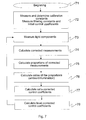
- FIG. 7 is a flow diagram illustrating a method for adjusting the illumination system of FIG. 6 .
- the flow diagram covers the initial configuration of the adjustment system and the phases related to its normal operation, the description of which will support the understanding of the invention.
- the illumination system of FIG. 6 is based on a gradually proceeding iterative process where the difference in the ratios of the light component intensities of illumination are measured with respect to ratios of the light component intensities of ambient light, and illumination is adjusted such that the whiteness of illumination would correspond to that of ambient light as well as possible.
- the brightness of illumination i.e. the sum of the light component intensities
- Brightness may also be adjusted intelligently such that brightness is increased in a low-light environment and reduced or completely switched off in a well-illuminated environment. In an alternative embodiment of the invention, this is carried out by an attempt to standardise the product of the brightness of illumination and brightness of ambient light, the brightness of illumination being thus inversely proportional to the brightness of ambient light.
- the flow diagram starts from block “begin”.
- level correction factors is ignored in this embodiment, although there is also an alternative embodiment where the output of the measurement units is corrected using not only correction coefficients but also level correction factors which are summed to the measurements preferably prior to the sensitivity correction.
- control coefficients are coefficients used for controlling the intensity of each light source of illumination on the next adjustment round.
- the device is taken in use and the actual adjustment process begins.
- the intensities (R, G, B) of the light components of illumination and those of ambient light are measured and multiplied by the correction coefficients to produce corrected intensities.
- the sum of the corrected intensities is calculated to obtain brightness.
- This is followed by calculating the proportion of the corrected intensity representing each light component of brightness, which allows the reciprocal ratios of the light components to be obtained.
- Table I also comprises a standard deviation calculated from the ratios of the proportions and illustrating a computational difference in whiteness between illumination and ambient light. The greater the standard deviation, the greater the difference will be determined.
- the proportion of the brightness of illumination with regard to the target is then calculated to be used later for adjusting brightness towards the target.
- the target value for brightness is 100 (in the units used in the table) and in the first measurement the proportion of brightness (brightness ratio) is 70.47% of the target.
- new control coefficients are calculated. This calculation is carried out in two phases. First, new control coefficients corrected according to the differences in the ratios of the proportions are calculated. Then the new control coefficients are level-corrected to adjust brightness towards the desired level.
- Each new ratio-corrected control coefficient (for R, G and B components) is calculated from the previous control coefficient on the basis of the ratio of the proportions of ambient light and illumination in the corresponding light component.
- the new ratio-corrected control coefficient is: the previous control coefficient ⁇ (1 ⁇ ratio correction factor+ratio correction factor ⁇ ratio).
- Table I shows the new control coefficients thus calculated:
- ratio correction aims at increasing illumination provided by components R and G and decreasing illumination provided by component B.
- the ratio correction factor for filtering the adjustment By applying the ratio correction factor for filtering the adjustment, the adjustment can be slowed down, which in turn provides improved adjustment stability.
- level-corrected control coefficients for controlling illumination are calculated for the next control round.
- level correction also employs filtering for stabilising the adjustment, i.e. for reducing oscillation tendency.
- the level-corrected control coefficient of R is calculated using the following formula:
- ratio-corrected control coefficient ⁇ (1 ⁇ level correction factor+level correction factor ⁇ (1/brightness ratio of illumination)
- the level-corrected control coefficients When the level-corrected control coefficients have been calculated, they are taken in use to replace the former control coefficients for controlling the intensities of the light components of illumination.
- the intensities change in the same proportion as the control coefficients, assuming that the electric components used for illumination, i.e. the LEDs in this case, are linear in their operation.
- the intensities of the light components are again measured with regard to both ambient light and illumination.
- the proportional change with regard to each previous measurement of a light component of the ambient is randomly determined, a new “measurement” being provided by the following equation:
- Table I shows a simulated example of the operation of the method of adjustment.
- Table II the simulation of Table I is followed during several adjustment rounds. Table II shows how the adjustment reduces both the difference of brightness with regard to the target (level difference, %) and the deviation in the ratios of the light components (the standard deviation, or st.dev.) On each adjustment round, new control coefficients are calculated for light sources corresponding to each light component, the coefficients being then used for operating the light sources.
- control coefficients round st. dev. level diff. % R G B 0 0.28346 29.5% 1 1 1 1 0.16753 21.1% 1.274 1.207 0.970 2 0.21909 25.2% 1.452 1.364 0.949 3 0.05642 4.9% 1.724 1.593 0.920 4 0.05745 3.4% 1.694 1.620 0.957 5 0.01882 2.5% 1.657 1.638 0.991 6 0.02412 0.5% 1.653 1.649 1.007 7 0.04765 ⁇ 0.6% 1.682 1.647 1.002 8 1.735 1.626 0.996
- Table II also shows that the standard deviation of the different colour components decreases faster than the level difference. The reason for this is the higher coefficient used in the filtering. Adjustment rounds are preferably carried out frequently and filtering is used to control that the changes in illumination are so small that the illumination does not appear to be flickering when the adjustment is in operation and yet the changes are carried out rapidly and conveniently.
- filtering factors of different values are provided in accordance with the direction of change of the illumination, the brightness of the illumination being increased more rapidly than decreased. This is advantageous for example when the invention is applied in a mobile station which may suddenly move into a shadow so that it is difficult to read the display properly. On the other hand, a display which is too brightly illuminated does not cause any major problems in viewing the display, but only wears the battery more rapidly. Choosing the correct filtering factors therefore has an impact on both ergonomics and the energy consumption of the device.
- control coefficients allow illumination to be adjusted by applying for example PWM control (Pulse Width Modulation).
- PWM control Pulse Width Modulation
- Each light source is controlled to illuminate the photoconductor with a pulsating light of a sufficiently high frequency (such as 25, 70 or 5000 Hz) to make it appear flicker-free.
- a PWM signal is used to implement illumination as a specific control-coefficient-dependent portion X of each sequence.
- X may be obtained for example by the following equation:
- control coefficient max is typically a pre-selected constant that exceeds the normal maximum value of the control coefficient.
- the control coefficient max may be a common factor for all control coefficients, or it may be separately set for each light component.
- the system comprises memory for storing previous colour balance measurements.
- the memory allows the system to adjust the colour balance of illumination even in situations where the intensity of ambient light becomes too low for any measurements.
- the memory can be used for implementing another alternative embodiment of the invention in which the liquid crystal display panel is illuminated with a pulsating light that has a high frequency, >20 Hz, with regard to the perception ability of the human eye.
- the colour balance meter is also used, during pauses in the illumination, for measuring the colour balance of ambient light and, during the illumination, for measuring the colour balance of illumination. This allows errors in measurement caused by differences between the measurement units to be completely avoided when the intensities of the light components of illumination and ambient light are to be evaluated. This also allows the above-described initial calibration to be left out without harming the white balance of the device. Although this may slightly change the brightness adjustment, because of a deviation in an individual measurement unit, the user may be provided with a manual brightness adjustment which allows the user to obtain the desired target level for brightness.
Abstract
Description
| R | G | B |
| 1.132 | 1.072 | 0.862 |
| TABLE I |
| A simulated example of the operation of the method of adjustment. |
| component |
| Correction constants | R | G | B | |
| Constants: | ||||
| ambient light | 2.125 | 1.800 | 1.600 | |
| illumination | 1.200 | 0.834 | 0.920 | |
| Ratio correction factor | 0.500 | |||
| level correction factor | 0.300 | |||
| random factor_1 | 0.100 | |||
| random factor_2 | 0.050 | |||
| illumination target sum: | 100 | Total: | ||
| illumination control | 1.000 | 1.000 | 1.000 | 3 |
| coefficients at the | ||||
| | ||||
| Measurement | ||||
| 1 | ||||
| ambient light | 4.000 | 11.000 | 7.000 | |
| illumination | 10.000 | 37.000 | 30.000 | |
| |
total: |
| ambient light | 8.499 | 19.800 | 11.200 | 39.4988 |
| illumination | 12.000 | 30.865 | 27.600 | 70.4654 |
| of the | 70.47% | |||
| target: |
| The ratio of |
| sum of the components |
| ambient light | 0.215 | 0.501 | 0.284 | |
| illumination | 0.170 | 0.438 | 0.392 | st. dev. |
| ratio | 1.263 | 1.144 | 0.724 | 0.2835 |
| New control coefficients | Total: | |||
| ratio-corrected: | 1.132 | 1.072 | 0.862 | |
| level-corrected: | 1.274 | 1.207 | 0.970 | 3.4514 |
| ratio to | 115.0% | |||
| |
| Adjustment round |
| 1, new measurements: |
| ambient light | 4.078 | 11.283 | 6.920 | |
| illumination | 12.817 | 43.883 | 29.220 |
| Measurements 2 corrected with correction coefficients | total: |
| ambient light | 8.664 | 20.309 | 11.072 | 40.0450 |
| illumination | 15.381 | 36.607 | 26.882 | 78.8698 |
| of the | 78.87% | |||
| target: |
| The ratio of measurements 2 corrected with correction coefficients to the |
| sum of the components |
| ambient light | 0.216 | 0.507 | 0.276 | |
| illumination | 0.195 | 0.464 | 0.341 | st. dev. |
| ratio | 1.109 | 1.093 | 0.811 | 0.1675 |
| New control coefficients | Total: | |||
| ratio-corrected: | 1.344 | 1.263 | 0.879 | |
| level-corrected: | 1.452 | 1.364 | 0.949 | 3.7656 |
| ratio to | 109.1% | |||
| previous |
| Adjustment round 2, new measurements: |
| ambient light | 3.981 | 11.576 | 6.732 | |
| illumination | 11.369 | 41.631 | 28.731 |
| Measurements 3 corrected with correction coefficients | total: |
| ambient light | 8.458 | 20.837 | 10.771 | 40.0664 |
| illumination | 13.643 | 34.728 | 26.432 | 74.8031 |
| of the | 74.80% | |||
| target: |
| The ratio of measurements 3 corrected with correction coefficients to the |
| sum of the components |
| ambient light | 0.211 | 0.520 | 0.269 | |
| illumination | 0.182 | 0.464 | 0.353 | st. dev. |
| ratio | 1.158 | 1.120 | 0.761 | 0.2191 |
| New control coefficients | Total: | |||
| ratio-corrected: | 1.566 | 1.446 | 0.836 | |
| level-corrected: | 1.724 | 1.593 | 0.920 | 4.2373 |
| ratio to | 112.5% | |||
| previous | ||||
| TABLE II |
| Operation of illumination adjustment during several control rounds |
| control coefficients |
| round: | st. dev. | level diff. % | R | G | B | ||
| 0 | 0.28346 | 29.5% | 1 | 1 | 1 | ||
| 1 | 0.16753 | 21.1% | 1.274 | 1.207 | 0.970 | ||
| 2 | 0.21909 | 25.2% | 1.452 | 1.364 | 0.949 | ||
| 3 | 0.05642 | 4.9% | 1.724 | 1.593 | 0.920 | ||
| 4 | 0.05745 | 3.4% | 1.694 | 1.620 | 0.957 | ||
| 5 | 0.01882 | 2.5% | 1.657 | 1.638 | 0.991 | ||
| 6 | 0.02412 | 0.5% | 1.653 | 1.649 | 1.007 | ||
| 7 | 0.04765 | −0.6% | 1.682 | 1.647 | 1.002 | ||
| 8 | 1.735 | 1.626 | 0.996 | ||||
Claims (20)
Applications Claiming Priority (3)
| Application Number | Priority Date | Filing Date | Title |
|---|---|---|---|
| FI002430 | 2000-11-06 | ||
| FI20002430A FI109632B (en) | 2000-11-06 | 2000-11-06 | White lighting |
| FI20002430 | 2000-11-06 |
Publications (2)
| Publication Number | Publication Date |
|---|---|
| US20020113192A1 US20020113192A1 (en) | 2002-08-22 |
| US6674060B2 true US6674060B2 (en) | 2004-01-06 |
Family
ID=8559439
Family Applications (1)
| Application Number | Title | Priority Date | Filing Date |
|---|---|---|---|
| US09/985,729 Expired - Lifetime US6674060B2 (en) | 2000-11-06 | 2001-11-06 | Method and apparatus for illuminating an object with white light |
Country Status (6)
| Country | Link |
|---|---|
| US (1) | US6674060B2 (en) |
| EP (1) | EP1336171B1 (en) |
| CN (1) | CN100385490C (en) |
| AU (1) | AU2002216003A1 (en) |
| FI (1) | FI109632B (en) |
| WO (1) | WO2002037454A2 (en) |
Cited By (62)
| Publication number | Priority date | Publication date | Assignee | Title |
|---|---|---|---|---|
| US20030178550A1 (en) * | 2002-02-12 | 2003-09-25 | Konica Corporation | Image reading apparatus |
| US20030210221A1 (en) * | 2002-05-08 | 2003-11-13 | Milivoje Aleksic | Portable device for providing LCD display and method thereof |
| US20040052076A1 (en) * | 1997-08-26 | 2004-03-18 | Mueller George G. | Controlled lighting methods and apparatus |
| US20050058450A1 (en) * | 2003-09-12 | 2005-03-17 | Isao Yamamoto | Light-emission control circuit |
| US20050200315A1 (en) * | 2004-03-11 | 2005-09-15 | Kwong Yin L. | Sampling for color control feedback using an optical cable |
| US20050259193A1 (en) * | 2004-05-24 | 2005-11-24 | Nec Corporation | Light source, display device, portable terminal device, and ray direction switching element |
| US20050270776A1 (en) * | 2004-06-04 | 2005-12-08 | Allen David W | Portable LED-illuminated radiance source |
| US20060000963A1 (en) * | 2004-06-30 | 2006-01-05 | Ng Kee Y | Light source calibration |
| US20060103612A1 (en) * | 2003-04-01 | 2006-05-18 | Yutaka Ozaki | Led driving device and led driving method |
| US20060214597A1 (en) * | 2005-03-07 | 2006-09-28 | Fuji Photo Film Co., Ltd. | Method of correcting amount of light emitted from an exposure head and exposure apparatus |
| US20060256049A1 (en) * | 2003-04-25 | 2006-11-16 | Thales | Automatic photo-colorimetric paratmeter control device for light boxes with colour leds |
| US20070097333A1 (en) * | 2005-10-31 | 2007-05-03 | Masoud Zavarehi | Determining an adjustment |
| US20070115228A1 (en) * | 2005-11-18 | 2007-05-24 | Roberts John K | Systems and methods for calibrating solid state lighting panels |
| US20070115670A1 (en) * | 2005-11-18 | 2007-05-24 | Roberts John K | Tiles for solid state lighting panels |
| US20070278974A1 (en) * | 2006-05-31 | 2007-12-06 | Led Lighting Fixtures, Inc. | Lighting device with color control, and method of lighting |
| US20080191643A1 (en) * | 2007-02-14 | 2008-08-14 | Cree, Inc. | Systems and Methods for Split Processor Control in a Solid State Lighting Panel |
| US20080291669A1 (en) * | 2007-05-21 | 2008-11-27 | Cree, Inc. | Solid state lighting panels with limited color gamut and methods of limiting color gamut in solid state lighting panels |
| US20080309255A1 (en) * | 2007-05-08 | 2008-12-18 | Cree Led Lighting Solutions, Inc | Lighting devices and methods for lighting |
| US20090001251A1 (en) * | 2007-06-27 | 2009-01-01 | Pak Hong Ng | Methods and apparatus for backlight calibration |
| US20090033612A1 (en) * | 2007-07-31 | 2009-02-05 | Roberts John K | Correction of temperature induced color drift in solid state lighting displays |
| US20090040674A1 (en) * | 2007-08-10 | 2009-02-12 | Cree, Inc. | Systems and methods for protecting display components from adverse operating conditions |
| US20090109129A1 (en) * | 2007-10-30 | 2009-04-30 | Seen Yee Cheong | System and Method for Managing Information Handling System Display Illumination |
| US20090153450A1 (en) * | 2007-12-18 | 2009-06-18 | Roberts John K | Systems and Methods for Providing Color Management Control in a Lighting Panel |
| US20090160363A1 (en) * | 2007-11-28 | 2009-06-25 | Cree Led Lighting Solutions, Inc. | Solid state lighting devices and methods of manufacturing the same |
| WO2009034515A3 (en) * | 2007-09-11 | 2009-07-09 | Philips Intellectual Property | Ambient light compensation sensor and procedure |
| US20090213041A1 (en) * | 2008-02-21 | 2009-08-27 | Robert Allan Unger | Solar backlight for transmissive displays |
| US20100123403A1 (en) * | 2008-11-17 | 2010-05-20 | Reed William G | Electronic control to regulate power for solid-state lighting and methods thereof |
| US20100231704A1 (en) * | 2009-03-16 | 2010-09-16 | PT Papertech, Inc. | Method and apparatus for a web inspection system |
| US20100277082A1 (en) * | 2009-05-01 | 2010-11-04 | Reed William G | Gas-discharge lamp replacement with passive cooling |
| US20100295946A1 (en) * | 2009-05-20 | 2010-11-25 | Reed William G | Long-range motion detection for illumination control |
| US7926300B2 (en) | 2005-11-18 | 2011-04-19 | Cree, Inc. | Adaptive adjustment of light output of solid state lighting panels |
| US8008676B2 (en) | 2006-05-26 | 2011-08-30 | Cree, Inc. | Solid state light emitting device and method of making same |
| US20120013650A1 (en) * | 2009-06-19 | 2012-01-19 | Sharp Kabushiki Kaisha | Display device |
| US8165786B2 (en) | 2005-10-21 | 2012-04-24 | Honeywell International Inc. | System for particulate matter sensor signal processing |
| US8514210B2 (en) | 2005-11-18 | 2013-08-20 | Cree, Inc. | Systems and methods for calibrating solid state lighting panels using combined light output measurements |
| US8896215B2 (en) | 2012-09-05 | 2014-11-25 | Express Imaging Systems, Llc | Apparatus and method for schedule based operation of a luminaire |
| US8987992B2 (en) | 2009-05-20 | 2015-03-24 | Express Imaging Systems, Llc | Apparatus and method of energy efficient illumination |
| US9131552B2 (en) | 2012-07-25 | 2015-09-08 | Express Imaging Systems, Llc | Apparatus and method of operating a luminaire |
| US9185777B2 (en) | 2014-01-30 | 2015-11-10 | Express Imaging Systems, Llc | Ambient light control in solid state lamps and luminaires |
| US9210751B2 (en) | 2012-05-01 | 2015-12-08 | Express Imaging Systems, Llc | Solid state lighting, drive circuit and method of driving same |
| US9277617B2 (en) | 2011-06-01 | 2016-03-01 | Thales | Device for controlling light-emitting diodes with very high luminance range for viewing screen |
| US9288873B2 (en) | 2013-02-13 | 2016-03-15 | Express Imaging Systems, Llc | Systems, methods, and apparatuses for using a high current switching device as a logic level sensor |
| US9301365B2 (en) | 2012-11-07 | 2016-03-29 | Express Imaging Systems, Llc | Luminaire with switch-mode converter power monitoring |
| US9360198B2 (en) | 2011-12-06 | 2016-06-07 | Express Imaging Systems, Llc | Adjustable output solid-state lighting device |
| US9414449B2 (en) | 2013-11-18 | 2016-08-09 | Express Imaging Systems, Llc | High efficiency power controller for luminaire |
| US9445485B2 (en) | 2014-10-24 | 2016-09-13 | Express Imaging Systems, Llc | Detection and correction of faulty photo controls in outdoor luminaires |
| US9462662B1 (en) | 2015-03-24 | 2016-10-04 | Express Imaging Systems, Llc | Low power photocontrol for luminaire |
| US9466443B2 (en) | 2013-07-24 | 2016-10-11 | Express Imaging Systems, Llc | Photocontrol for luminaire consumes very low power |
| US9497393B2 (en) | 2012-03-02 | 2016-11-15 | Express Imaging Systems, Llc | Systems and methods that employ object recognition |
| US9538612B1 (en) | 2015-09-03 | 2017-01-03 | Express Imaging Systems, Llc | Low power photocontrol for luminaire |
| US9572230B2 (en) | 2014-09-30 | 2017-02-14 | Express Imaging Systems, Llc | Centralized control of area lighting hours of illumination |
| US9924582B2 (en) | 2016-04-26 | 2018-03-20 | Express Imaging Systems, Llc | Luminaire dimming module uses 3 contact NEMA photocontrol socket |
| US9985429B2 (en) | 2016-09-21 | 2018-05-29 | Express Imaging Systems, Llc | Inrush current limiter circuit |
| US10098212B2 (en) | 2017-02-14 | 2018-10-09 | Express Imaging Systems, Llc | Systems and methods for controlling outdoor luminaire wireless network using smart appliance |
| US10219360B2 (en) | 2017-04-03 | 2019-02-26 | Express Imaging Systems, Llc | Systems and methods for outdoor luminaire wireless control |
| US10230296B2 (en) | 2016-09-21 | 2019-03-12 | Express Imaging Systems, Llc | Output ripple reduction for power converters |
| US10568191B2 (en) | 2017-04-03 | 2020-02-18 | Express Imaging Systems, Llc | Systems and methods for outdoor luminaire wireless control |
| US10904992B2 (en) | 2017-04-03 | 2021-01-26 | Express Imaging Systems, Llc | Systems and methods for outdoor luminaire wireless control |
| US11212887B2 (en) | 2019-11-04 | 2021-12-28 | Express Imaging Systems, Llc | Light having selectively adjustable sets of solid state light sources, circuit and method of operation thereof, to provide variable output characteristics |
| US11234304B2 (en) | 2019-05-24 | 2022-01-25 | Express Imaging Systems, Llc | Photocontroller to control operation of a luminaire having a dimming line |
| US11317497B2 (en) | 2019-06-20 | 2022-04-26 | Express Imaging Systems, Llc | Photocontroller and/or lamp with photocontrols to control operation of lamp |
| US11375599B2 (en) | 2017-04-03 | 2022-06-28 | Express Imaging Systems, Llc | Systems and methods for outdoor luminaire wireless control |
Families Citing this family (61)
| Publication number | Priority date | Publication date | Assignee | Title |
|---|---|---|---|---|
| AU7730800A (en) * | 1999-09-29 | 2001-04-30 | Color Kinetics Incorporated | Systems and methods for calibrating light output by light-emitting diodes |
| KR100845148B1 (en) * | 2002-07-03 | 2008-07-09 | 이노베이티브 솔루션즈 앤드 서포트 인코포레이티드 | Method and Apparatus for Illuminating a Flat Panel Display with a Variably-Adjustable Backlight |
| DE10260692B4 (en) * | 2002-12-23 | 2009-05-20 | Continental Automotive Gmbh | liquid-crystal display |
| JP2004309509A (en) * | 2003-04-01 | 2004-11-04 | Hunet Inc | Method for adjusting display device |
| CN100419534C (en) * | 2003-12-08 | 2008-09-17 | 索尼株式会社 | Liquid crystal display and backlight adjusting method |
| US7339332B2 (en) * | 2004-05-24 | 2008-03-04 | Honeywell International, Inc. | Chroma compensated backlit display |
| US7759622B2 (en) * | 2004-09-10 | 2010-07-20 | Avago Technologies Ecbu Ip (Singapore) Pte. Ltd. | Methods and apparatus for regulating the drive currents of a plurality of light emitters |
| EP1646033A1 (en) * | 2004-10-05 | 2006-04-12 | Research In Motion Limited | Method for maintaining the white colour point over time in a field-sequential colour LCD |
| US7714829B2 (en) | 2004-10-05 | 2010-05-11 | Research In Motion Limited | Method for maintaining the white colour point in a field-sequential LCD over time |
| US7348530B2 (en) * | 2004-10-05 | 2008-03-25 | Avago Technologies Ecbu Ip Pte Ltd | System, method and apparatus for regulating the light emitted by a light source |
| US20060087841A1 (en) * | 2004-10-27 | 2006-04-27 | United Epitaxy Company, Ltd. | LED luminaire with feedback control |
| JP4438722B2 (en) | 2004-11-19 | 2010-03-24 | ソニー株式会社 | Backlight driving device, backlight driving method, and liquid crystal display device |
| DE602005020347D1 (en) * | 2004-11-19 | 2010-05-12 | Koninkl Philips Electronics Nv | FEEDBACK SYSTEM FOR CONTROLLING THE LIGHTING PERFORMANCE OF A LED UNIT |
| US7324080B1 (en) * | 2004-12-03 | 2008-01-29 | Sysview Technology, Inc. | Backlighting in liquid crystal flat panel display |
| US7607797B2 (en) * | 2005-01-06 | 2009-10-27 | S.C. Johnson & Son, Inc. | Microcontroller-controlled multi-color LED apparatus |
| JP2008089619A (en) * | 2005-03-29 | 2008-04-17 | Sharp Corp | Display device and electronic apparatus |
| WO2006134029A1 (en) * | 2005-06-13 | 2006-12-21 | Sony Ericsson Mobile Communications Ab | Illumination in a portable communication device |
| EP1734502A1 (en) * | 2005-06-13 | 2006-12-20 | Sony Ericsson Mobile Communications AB | Illumination in a portable communication device |
| JP2009519486A (en) * | 2005-12-13 | 2009-05-14 | コーニンクレッカ フィリップス エレクトロニクス エヌ ヴィ | Display device with ambient light detection |
| US8232512B2 (en) * | 2006-04-10 | 2012-07-31 | Avago Technologies Ecbu Ip (Singapore) Pte. Ltd. | Method and apparatus for integrating a quantity of light |
| US7825891B2 (en) | 2006-06-02 | 2010-11-02 | Apple Inc. | Dynamic backlight control system |
| US20080055065A1 (en) * | 2006-08-30 | 2008-03-06 | David Charles Feldmeier | Systems, devices, components and methods for controllably configuring the brightness of light emitted by an automotive LED illumination system |
| US20080055896A1 (en) * | 2006-08-30 | 2008-03-06 | David Charles Feldmeier | Systems, devices, components and methods for controllably configuring the color of light emitted by an automotive LED illumination system |
| JP4607846B2 (en) | 2006-10-19 | 2011-01-05 | ソニー株式会社 | Light source device, light source driving device, light emission amount control device, and liquid crystal display device |
| KR20080051302A (en) | 2006-12-05 | 2008-06-11 | 삼성전자주식회사 | User terminal apparatus and image display apparatus and method for adjusting light source thereof |
| DE102007004834A1 (en) * | 2007-01-31 | 2008-08-14 | Airbus Deutschland Gmbh | Light device and method for realizing a desired color mixture |
| US20080303918A1 (en) * | 2007-06-11 | 2008-12-11 | Micron Technology, Inc. | Color correcting for ambient light |
| TW200925491A (en) | 2007-11-06 | 2009-06-16 | Koninkl Philips Electronics Nv | Light control system and method for automatically rendering a lighting atmosphere |
| KR101588035B1 (en) | 2007-11-06 | 2016-01-25 | 코닌클리케 필립스 엔.브이. | Light control system and method for automatically rendering a lighting scene |
| US7960682B2 (en) | 2007-12-13 | 2011-06-14 | Apple Inc. | Display device control based on integrated ambient light detection and lighting source characteristics |
| EP2075787A3 (en) | 2007-12-26 | 2010-07-07 | TPO Displays Corp. | Display devices with ambient light sensing |
| US20090222339A1 (en) * | 2008-03-03 | 2009-09-03 | The Coca-Cola Company | Systems and Methods for Providing a Personal Terminal for a Loyalty Program |
| US20090237423A1 (en) * | 2008-03-20 | 2009-09-24 | Capella Microsystems, Corp. | Display apparatus of adjusting gamma and brightness based on ambient light and its display adjustment method |
| US8390562B2 (en) * | 2009-03-24 | 2013-03-05 | Apple Inc. | Aging based white point control in backlights |
| DE102009018233A1 (en) * | 2009-04-21 | 2010-10-28 | Ledon Lighting Jennersdorf Gmbh | Method and lighting system for operating a multi-channel LED module |
| FR2948776B1 (en) * | 2009-07-31 | 2011-08-19 | Thales Sa | METHOD OF CONSTRUCTING IMAGES FOR IMAGING APPARATUS |
| IT1397754B1 (en) * | 2009-10-29 | 2013-01-24 | Cocchi | VOTIVE AND CEMETERIAL LIGHTING SYSTEM WITH PSYCHO-OPTICAL EFFECT WITH LED DIODES. |
| CA2779965A1 (en) * | 2009-12-17 | 2011-06-23 | Alcon Research, Ltd. | Photonic lattice leds for ophthalmic illumination |
| JP5948025B2 (en) * | 2010-08-06 | 2016-07-06 | 株式会社半導体エネルギー研究所 | Liquid crystal display |
| WO2012075188A1 (en) * | 2010-11-30 | 2012-06-07 | The Sloan Company, Inc. Dba Sloanled | Power control unit |
| US8901825B2 (en) | 2011-04-12 | 2014-12-02 | Express Imaging Systems, Llc | Apparatus and method of energy efficient illumination using received signals |
| US8610358B2 (en) | 2011-08-17 | 2013-12-17 | Express Imaging Systems, Llc | Electrostatic discharge protection for luminaire |
| WO2013028834A1 (en) | 2011-08-24 | 2013-02-28 | Express Imaging Systems, Llc | Resonant network for reduction of flicker perception in solid state lighting systems |
| US9477263B2 (en) | 2011-10-27 | 2016-10-25 | Apple Inc. | Electronic device with chip-on-glass ambient light sensors |
| EP2781138A4 (en) | 2011-11-18 | 2015-10-28 | Express Imaging Systems Llc | Adjustable output solid-state lamp with security features |
| US9582083B2 (en) | 2011-12-22 | 2017-02-28 | Apple Inc. | Directional light sensors |
| US9204523B2 (en) | 2012-05-02 | 2015-12-01 | Express Imaging Systems, Llc | Remotely adjustable solid-state lamp |
| CN102821519A (en) * | 2012-08-06 | 2012-12-12 | 湖北天罡投资有限公司 | Illuminating device and method |
| US8878440B2 (en) | 2012-08-28 | 2014-11-04 | Express Imaging Systems, Llc | Luminaire with atmospheric electrical activity detection and visual alert capabilities |
| US9024530B2 (en) | 2012-11-13 | 2015-05-05 | Apple Inc. | Synchronized ambient light sensor and display |
| US9129548B2 (en) | 2012-11-15 | 2015-09-08 | Apple Inc. | Ambient light sensors with infrared compensation |
| US9210759B2 (en) | 2012-11-19 | 2015-12-08 | Express Imaging Systems, Llc | Luminaire with ambient sensing and autonomous control capabilities |
| US9070648B2 (en) | 2012-11-27 | 2015-06-30 | Apple Inc. | Electronic devices with display-integrated light sensors |
| US8987652B2 (en) | 2012-12-13 | 2015-03-24 | Apple Inc. | Electronic device with display and low-noise ambient light sensor with a control circuitry that periodically disables the display |
| US9310843B2 (en) | 2013-01-02 | 2016-04-12 | Apple Inc. | Electronic devices with light sensors and displays |
| US20150070402A1 (en) * | 2013-09-12 | 2015-03-12 | Qualcomm Incorporated | Real-time color calibration of displays |
| US9965999B1 (en) * | 2014-06-26 | 2018-05-08 | Amazon Technologies, Inc. | Adjusting display color based on brightness |
| US20160178832A1 (en) * | 2014-12-22 | 2016-06-23 | Shenzhen China Star Optoelectronics Technology Co., Ltd. | Backlight module, transparent display panel and transparent display apparatus |
| US10644077B1 (en) | 2015-10-28 | 2020-05-05 | Apple Inc. | Display with array of light-transmitting windows |
| US10157590B1 (en) | 2015-12-15 | 2018-12-18 | Apple Inc. | Display with localized brightness adjustment capabilities |
| US10163984B1 (en) | 2016-09-12 | 2018-12-25 | Apple Inc. | Display with embedded components and subpixel windows |
Citations (7)
| Publication number | Priority date | Publication date | Assignee | Title |
|---|---|---|---|---|
| US5731794A (en) | 1994-02-17 | 1998-03-24 | Kazuo Aoki | Color panel display device |
| US5748237A (en) * | 1993-12-20 | 1998-05-05 | Sony Corporation | Backlighting and color control arrangement for LCD type video camera viewfinder having multiple backlighting sources |
| US5886681A (en) | 1996-06-14 | 1999-03-23 | Walsh; Kevin L. | Wide-range dual-backlight display apparatus |
| JPH11295689A (en) | 1998-04-10 | 1999-10-29 | Matsushita Electric Ind Co Ltd | Liquid crystal display device |
| US5998925A (en) | 1996-07-29 | 1999-12-07 | Nichia Kagaku Kogyo Kabushiki Kaisha | Light emitting device having a nitride compound semiconductor and a phosphor containing a garnet fluorescent material |
| WO1999063515A1 (en) | 1998-05-29 | 1999-12-09 | Silicon Graphics, Inc. | Color balancing system for display apparatus |
| EP1077444A2 (en) | 1999-08-11 | 2001-02-21 | Agilent Technologies Inc | System and method for on-chip calibration of illumination sources for an integrated circuit display |
Family Cites Families (4)
| Publication number | Priority date | Publication date | Assignee | Title |
|---|---|---|---|---|
| JPH11508420A (en) * | 1995-06-20 | 1999-07-21 | トムソン コンシューマ エレクトロニクス インコーポレイテッド | Electronic finder with backlight |
| JP4050802B2 (en) | 1996-08-02 | 2008-02-20 | シチズン電子株式会社 | Color display device |
| CN1118181C (en) * | 1997-09-30 | 2003-08-13 | 株式会社理光 | Digital camera |
| US6611249B1 (en) * | 1998-07-22 | 2003-08-26 | Silicon Graphics, Inc. | System and method for providing a wide aspect ratio flat panel display monitor independent white-balance adjustment and gamma correction capabilities |
-
2000
- 2000-11-06 FI FI20002430A patent/FI109632B/en not_active IP Right Cessation
-
2001
- 2001-11-02 EP EP01992993.4A patent/EP1336171B1/en not_active Expired - Lifetime
- 2001-11-02 AU AU2002216003A patent/AU2002216003A1/en not_active Abandoned
- 2001-11-02 WO PCT/EP2001/012735 patent/WO2002037454A2/en not_active Application Discontinuation
- 2001-11-02 CN CNB018184790A patent/CN100385490C/en not_active Expired - Fee Related
- 2001-11-06 US US09/985,729 patent/US6674060B2/en not_active Expired - Lifetime
Patent Citations (8)
| Publication number | Priority date | Publication date | Assignee | Title |
|---|---|---|---|---|
| US5748237A (en) * | 1993-12-20 | 1998-05-05 | Sony Corporation | Backlighting and color control arrangement for LCD type video camera viewfinder having multiple backlighting sources |
| US5731794A (en) | 1994-02-17 | 1998-03-24 | Kazuo Aoki | Color panel display device |
| US5886681A (en) | 1996-06-14 | 1999-03-23 | Walsh; Kevin L. | Wide-range dual-backlight display apparatus |
| US5998925A (en) | 1996-07-29 | 1999-12-07 | Nichia Kagaku Kogyo Kabushiki Kaisha | Light emitting device having a nitride compound semiconductor and a phosphor containing a garnet fluorescent material |
| JPH11295689A (en) | 1998-04-10 | 1999-10-29 | Matsushita Electric Ind Co Ltd | Liquid crystal display device |
| WO1999063515A1 (en) | 1998-05-29 | 1999-12-09 | Silicon Graphics, Inc. | Color balancing system for display apparatus |
| EP1077444A2 (en) | 1999-08-11 | 2001-02-21 | Agilent Technologies Inc | System and method for on-chip calibration of illumination sources for an integrated circuit display |
| US6344641B1 (en) * | 1999-08-11 | 2002-02-05 | Agilent Technologies, Inc. | System and method for on-chip calibration of illumination sources for an integrated circuit display |
Non-Patent Citations (2)
| Title |
|---|
| Brightness and Color Temperature Control on Thin Film Transistor/Liquid Crystal Display, IBM Technical Disclosure Bulletin, vol. 40, No. 8, Aug. 1997, p27. |
| White Balance Control Method on Liquid Crystal Display, IBM Technical Disclosure Bulletin, vol. 37, No. 11, Nov. 1994, pp. 425-426. |
Cited By (111)
| Publication number | Priority date | Publication date | Assignee | Title |
|---|---|---|---|---|
| US20040052076A1 (en) * | 1997-08-26 | 2004-03-18 | Mueller George G. | Controlled lighting methods and apparatus |
| US20030178550A1 (en) * | 2002-02-12 | 2003-09-25 | Konica Corporation | Image reading apparatus |
| US7022960B2 (en) * | 2002-02-12 | 2006-04-04 | Konica Corporation | Photographic film image reading apparatus with film density detection |
| US20030210221A1 (en) * | 2002-05-08 | 2003-11-13 | Milivoje Aleksic | Portable device for providing LCD display and method thereof |
| US20060103612A1 (en) * | 2003-04-01 | 2006-05-18 | Yutaka Ozaki | Led driving device and led driving method |
| US7425801B2 (en) * | 2003-04-01 | 2008-09-16 | Hunet Display Technology Inc. | LED driving device for multiple color LED displays |
| US7804478B2 (en) * | 2003-04-25 | 2010-09-28 | Thales | Feedback control device for photo-colorimetric parameters for a light box with color LEDs |
| US20060256049A1 (en) * | 2003-04-25 | 2006-11-16 | Thales | Automatic photo-colorimetric paratmeter control device for light boxes with colour leds |
| US7423626B2 (en) * | 2003-09-12 | 2008-09-09 | Rohm Co., Ltd. | Light-emission control circuit |
| US20050058450A1 (en) * | 2003-09-12 | 2005-03-17 | Isao Yamamoto | Light-emission control circuit |
| US20090039234A1 (en) * | 2003-09-12 | 2009-02-12 | Rohm Co., Ltd. | Light-emission control circuit |
| US20050200315A1 (en) * | 2004-03-11 | 2005-09-15 | Kwong Yin L. | Sampling for color control feedback using an optical cable |
| US7108413B2 (en) * | 2004-03-11 | 2006-09-19 | Avago Technologies Ecbu Ip (Singapore) Pte. Ltd. | Sampling for color control feedback using an optical cable |
| US7349043B2 (en) * | 2004-05-24 | 2008-03-25 | Nec Corporation | Light source, display device, portable terminal device, and ray direction switching element |
| US20090135336A1 (en) * | 2004-05-24 | 2009-05-28 | Nec Corporation | Light source, display device, portable terminal device, and ray direction switching element |
| US20050259193A1 (en) * | 2004-05-24 | 2005-11-24 | Nec Corporation | Light source, display device, portable terminal device, and ray direction switching element |
| US7728925B2 (en) | 2004-05-24 | 2010-06-01 | Nec Corporation | Light source, display device, portable terminal device, and ray direction switching element |
| US7630026B2 (en) | 2004-05-24 | 2009-12-08 | Nec Corporation | Planar light source, display device, portable terminal device, and ray direction switching element |
| US7499123B2 (en) | 2004-05-24 | 2009-03-03 | Nec Corporation | Planar light source, display device, portable terminal device, and ray direction switching element |
| US20080137000A1 (en) * | 2004-05-24 | 2008-06-12 | Nec Corporation | Planar light source, display device, portable terminal device, and ray direction switching element |
| US7929077B2 (en) | 2004-05-24 | 2011-04-19 | Nec Corporation | Light source, display device, portable terminal device, and ray direction switching element |
| US20080205083A1 (en) * | 2004-05-24 | 2008-08-28 | Nec Corporation | Planar light source, display device, portable terminal device, and ray direction switching element |
| US7628507B2 (en) * | 2004-06-04 | 2009-12-08 | The United States of America as represented by the Secretary of Commerce, the National Institute of Standards and Technology | Radiance output and temperature controlled LED radiance source |
| US20050270776A1 (en) * | 2004-06-04 | 2005-12-08 | Allen David W | Portable LED-illuminated radiance source |
| US20060000963A1 (en) * | 2004-06-30 | 2006-01-05 | Ng Kee Y | Light source calibration |
| US20060214597A1 (en) * | 2005-03-07 | 2006-09-28 | Fuji Photo Film Co., Ltd. | Method of correcting amount of light emitted from an exposure head and exposure apparatus |
| US8165786B2 (en) | 2005-10-21 | 2012-04-24 | Honeywell International Inc. | System for particulate matter sensor signal processing |
| US20070097333A1 (en) * | 2005-10-31 | 2007-05-03 | Masoud Zavarehi | Determining an adjustment |
| US7614753B2 (en) * | 2005-10-31 | 2009-11-10 | Hewlett-Packard Development Company, L.P. | Determining an adjustment |
| US20090219714A1 (en) * | 2005-11-18 | 2009-09-03 | Negley Gerald H | Tile for Solid State Lighting |
| US7959325B2 (en) | 2005-11-18 | 2011-06-14 | Cree, Inc. | Solid state lighting units and methods of forming solid state lighting units |
| US8514210B2 (en) | 2005-11-18 | 2013-08-20 | Cree, Inc. | Systems and methods for calibrating solid state lighting panels using combined light output measurements |
| US7926300B2 (en) | 2005-11-18 | 2011-04-19 | Cree, Inc. | Adaptive adjustment of light output of solid state lighting panels |
| US7993021B2 (en) | 2005-11-18 | 2011-08-09 | Cree, Inc. | Multiple color lighting element cluster tiles for solid state lighting panels |
| US8123375B2 (en) | 2005-11-18 | 2012-02-28 | Cree, Inc. | Tile for solid state lighting |
| US8278846B2 (en) | 2005-11-18 | 2012-10-02 | Cree, Inc. | Systems and methods for calibrating solid state lighting panels |
| US20070115671A1 (en) * | 2005-11-18 | 2007-05-24 | Roberts John K | Solid state lighting units and methods of forming solid state lighting units |
| US8556464B2 (en) | 2005-11-18 | 2013-10-15 | Cree, Inc. | Solid state lighting units and methods of forming solid state lighting units |
| US20070115228A1 (en) * | 2005-11-18 | 2007-05-24 | Roberts John K | Systems and methods for calibrating solid state lighting panels |
| US20070115670A1 (en) * | 2005-11-18 | 2007-05-24 | Roberts John K | Tiles for solid state lighting panels |
| US8008676B2 (en) | 2006-05-26 | 2011-08-30 | Cree, Inc. | Solid state light emitting device and method of making same |
| US20070278974A1 (en) * | 2006-05-31 | 2007-12-06 | Led Lighting Fixtures, Inc. | Lighting device with color control, and method of lighting |
| US7969097B2 (en) | 2006-05-31 | 2011-06-28 | Cree, Inc. | Lighting device with color control, and method of lighting |
| US20080191643A1 (en) * | 2007-02-14 | 2008-08-14 | Cree, Inc. | Systems and Methods for Split Processor Control in a Solid State Lighting Panel |
| US8456388B2 (en) | 2007-02-14 | 2013-06-04 | Cree, Inc. | Systems and methods for split processor control in a solid state lighting panel |
| US8174205B2 (en) | 2007-05-08 | 2012-05-08 | Cree, Inc. | Lighting devices and methods for lighting |
| US8981677B2 (en) | 2007-05-08 | 2015-03-17 | Cree, Inc. | Lighting devices and methods for lighting |
| US8441206B2 (en) | 2007-05-08 | 2013-05-14 | Cree, Inc. | Lighting devices and methods for lighting |
| US20080309255A1 (en) * | 2007-05-08 | 2008-12-18 | Cree Led Lighting Solutions, Inc | Lighting devices and methods for lighting |
| US7712917B2 (en) | 2007-05-21 | 2010-05-11 | Cree, Inc. | Solid state lighting panels with limited color gamut and methods of limiting color gamut in solid state lighting panels |
| US8449130B2 (en) | 2007-05-21 | 2013-05-28 | Cree, Inc. | Solid state lighting panels with limited color gamut and methods of limiting color gamut in solid state lighting panels |
| US20080291669A1 (en) * | 2007-05-21 | 2008-11-27 | Cree, Inc. | Solid state lighting panels with limited color gamut and methods of limiting color gamut in solid state lighting panels |
| US20090001251A1 (en) * | 2007-06-27 | 2009-01-01 | Pak Hong Ng | Methods and apparatus for backlight calibration |
| US8044899B2 (en) * | 2007-06-27 | 2011-10-25 | Hong Kong Applied Science and Technology Research Institute Company Limited | Methods and apparatus for backlight calibration |
| US20090033612A1 (en) * | 2007-07-31 | 2009-02-05 | Roberts John K | Correction of temperature induced color drift in solid state lighting displays |
| US20090040674A1 (en) * | 2007-08-10 | 2009-02-12 | Cree, Inc. | Systems and methods for protecting display components from adverse operating conditions |
| US8829820B2 (en) | 2007-08-10 | 2014-09-09 | Cree, Inc. | Systems and methods for protecting display components from adverse operating conditions |
| US20100308737A1 (en) * | 2007-09-11 | 2010-12-09 | Koninklijke Philips Electronics N.V. | Ambient light compensation sensor and procedure |
| US8207676B2 (en) * | 2007-09-11 | 2012-06-26 | Koninklijke Philips Electronics N.V. | Ambient light compensation sensor and procedure |
| WO2009034515A3 (en) * | 2007-09-11 | 2009-07-09 | Philips Intellectual Property | Ambient light compensation sensor and procedure |
| US20090109129A1 (en) * | 2007-10-30 | 2009-04-30 | Seen Yee Cheong | System and Method for Managing Information Handling System Display Illumination |
| US9491828B2 (en) | 2007-11-28 | 2016-11-08 | Cree, Inc. | Solid state lighting devices and methods of manufacturing the same |
| US8866410B2 (en) | 2007-11-28 | 2014-10-21 | Cree, Inc. | Solid state lighting devices and methods of manufacturing the same |
| US20090160363A1 (en) * | 2007-11-28 | 2009-06-25 | Cree Led Lighting Solutions, Inc. | Solid state lighting devices and methods of manufacturing the same |
| US8823630B2 (en) | 2007-12-18 | 2014-09-02 | Cree, Inc. | Systems and methods for providing color management control in a lighting panel |
| US20090153450A1 (en) * | 2007-12-18 | 2009-06-18 | Roberts John K | Systems and Methods for Providing Color Management Control in a Lighting Panel |
| US20090213041A1 (en) * | 2008-02-21 | 2009-08-27 | Robert Allan Unger | Solar backlight for transmissive displays |
| US9967933B2 (en) | 2008-11-17 | 2018-05-08 | Express Imaging Systems, Llc | Electronic control to regulate power for solid-state lighting and methods thereof |
| US20100123403A1 (en) * | 2008-11-17 | 2010-05-20 | Reed William G | Electronic control to regulate power for solid-state lighting and methods thereof |
| US9125261B2 (en) | 2008-11-17 | 2015-09-01 | Express Imaging Systems, Llc | Electronic control to regulate power for solid-state lighting and methods thereof |
| US20100231704A1 (en) * | 2009-03-16 | 2010-09-16 | PT Papertech, Inc. | Method and apparatus for a web inspection system |
| US8325225B2 (en) | 2009-03-16 | 2012-12-04 | PT Papertech, Inc | Method and apparatus for a web inspection system |
| US20100277082A1 (en) * | 2009-05-01 | 2010-11-04 | Reed William G | Gas-discharge lamp replacement with passive cooling |
| US8926139B2 (en) | 2009-05-01 | 2015-01-06 | Express Imaging Systems, Llc | Gas-discharge lamp replacement with passive cooling |
| US8987992B2 (en) | 2009-05-20 | 2015-03-24 | Express Imaging Systems, Llc | Apparatus and method of energy efficient illumination |
| US20100295946A1 (en) * | 2009-05-20 | 2010-11-25 | Reed William G | Long-range motion detection for illumination control |
| US8872964B2 (en) | 2009-05-20 | 2014-10-28 | Express Imaging Systems, Llc | Long-range motion detection for illumination control |
| US9478111B2 (en) | 2009-05-20 | 2016-10-25 | Express Imaging Systems, Llc | Long-range motion detection for illumination control |
| US20120013650A1 (en) * | 2009-06-19 | 2012-01-19 | Sharp Kabushiki Kaisha | Display device |
| US9277617B2 (en) | 2011-06-01 | 2016-03-01 | Thales | Device for controlling light-emitting diodes with very high luminance range for viewing screen |
| US9360198B2 (en) | 2011-12-06 | 2016-06-07 | Express Imaging Systems, Llc | Adjustable output solid-state lighting device |
| US9497393B2 (en) | 2012-03-02 | 2016-11-15 | Express Imaging Systems, Llc | Systems and methods that employ object recognition |
| US9210751B2 (en) | 2012-05-01 | 2015-12-08 | Express Imaging Systems, Llc | Solid state lighting, drive circuit and method of driving same |
| US9131552B2 (en) | 2012-07-25 | 2015-09-08 | Express Imaging Systems, Llc | Apparatus and method of operating a luminaire |
| US9801248B2 (en) | 2012-07-25 | 2017-10-24 | Express Imaging Systems, Llc | Apparatus and method of operating a luminaire |
| US9693433B2 (en) | 2012-09-05 | 2017-06-27 | Express Imaging Systems, Llc | Apparatus and method for schedule based operation of a luminaire |
| US8896215B2 (en) | 2012-09-05 | 2014-11-25 | Express Imaging Systems, Llc | Apparatus and method for schedule based operation of a luminaire |
| US9301365B2 (en) | 2012-11-07 | 2016-03-29 | Express Imaging Systems, Llc | Luminaire with switch-mode converter power monitoring |
| US9288873B2 (en) | 2013-02-13 | 2016-03-15 | Express Imaging Systems, Llc | Systems, methods, and apparatuses for using a high current switching device as a logic level sensor |
| US9466443B2 (en) | 2013-07-24 | 2016-10-11 | Express Imaging Systems, Llc | Photocontrol for luminaire consumes very low power |
| US9414449B2 (en) | 2013-11-18 | 2016-08-09 | Express Imaging Systems, Llc | High efficiency power controller for luminaire |
| US9781797B2 (en) | 2013-11-18 | 2017-10-03 | Express Imaging Systems, Llc | High efficiency power controller for luminaire |
| US9185777B2 (en) | 2014-01-30 | 2015-11-10 | Express Imaging Systems, Llc | Ambient light control in solid state lamps and luminaires |
| US9572230B2 (en) | 2014-09-30 | 2017-02-14 | Express Imaging Systems, Llc | Centralized control of area lighting hours of illumination |
| US9445485B2 (en) | 2014-10-24 | 2016-09-13 | Express Imaging Systems, Llc | Detection and correction of faulty photo controls in outdoor luminaires |
| US9462662B1 (en) | 2015-03-24 | 2016-10-04 | Express Imaging Systems, Llc | Low power photocontrol for luminaire |
| US9538612B1 (en) | 2015-09-03 | 2017-01-03 | Express Imaging Systems, Llc | Low power photocontrol for luminaire |
| US9924582B2 (en) | 2016-04-26 | 2018-03-20 | Express Imaging Systems, Llc | Luminaire dimming module uses 3 contact NEMA photocontrol socket |
| US9985429B2 (en) | 2016-09-21 | 2018-05-29 | Express Imaging Systems, Llc | Inrush current limiter circuit |
| US10230296B2 (en) | 2016-09-21 | 2019-03-12 | Express Imaging Systems, Llc | Output ripple reduction for power converters |
| US10098212B2 (en) | 2017-02-14 | 2018-10-09 | Express Imaging Systems, Llc | Systems and methods for controlling outdoor luminaire wireless network using smart appliance |
| US10219360B2 (en) | 2017-04-03 | 2019-02-26 | Express Imaging Systems, Llc | Systems and methods for outdoor luminaire wireless control |
| US10390414B2 (en) | 2017-04-03 | 2019-08-20 | Express Imaging Systems, Llc | Systems and methods for outdoor luminaire wireless control |
| US10568191B2 (en) | 2017-04-03 | 2020-02-18 | Express Imaging Systems, Llc | Systems and methods for outdoor luminaire wireless control |
| US10904992B2 (en) | 2017-04-03 | 2021-01-26 | Express Imaging Systems, Llc | Systems and methods for outdoor luminaire wireless control |
| US11375599B2 (en) | 2017-04-03 | 2022-06-28 | Express Imaging Systems, Llc | Systems and methods for outdoor luminaire wireless control |
| US11653436B2 (en) | 2017-04-03 | 2023-05-16 | Express Imaging Systems, Llc | Systems and methods for outdoor luminaire wireless control |
| US11234304B2 (en) | 2019-05-24 | 2022-01-25 | Express Imaging Systems, Llc | Photocontroller to control operation of a luminaire having a dimming line |
| US11317497B2 (en) | 2019-06-20 | 2022-04-26 | Express Imaging Systems, Llc | Photocontroller and/or lamp with photocontrols to control operation of lamp |
| US11765805B2 (en) | 2019-06-20 | 2023-09-19 | Express Imaging Systems, Llc | Photocontroller and/or lamp with photocontrols to control operation of lamp |
| US11212887B2 (en) | 2019-11-04 | 2021-12-28 | Express Imaging Systems, Llc | Light having selectively adjustable sets of solid state light sources, circuit and method of operation thereof, to provide variable output characteristics |
Also Published As
| Publication number | Publication date |
|---|---|
| FI20002430A0 (en) | 2000-11-06 |
| FI20002430A (en) | 2002-05-07 |
| WO2002037454A2 (en) | 2002-05-10 |
| EP1336171B1 (en) | 2015-07-29 |
| US20020113192A1 (en) | 2002-08-22 |
| AU2002216003A1 (en) | 2002-05-15 |
| WO2002037454A3 (en) | 2002-08-15 |
| CN100385490C (en) | 2008-04-30 |
| EP1336171A2 (en) | 2003-08-20 |
| FI109632B (en) | 2002-09-13 |
| CN1568496A (en) | 2005-01-19 |
Similar Documents
| Publication | Publication Date | Title |
|---|---|---|
| US6674060B2 (en) | Method and apparatus for illuminating an object with white light | |
| RU2443006C1 (en) | Display device | |
| US9099045B2 (en) | Backlight apparatus, backlight controlling method and liquid crystal display apparatus | |
| JP3939141B2 (en) | Projection type image display system and color correction method thereof | |
| EP2082620B1 (en) | Method and driver for determining drive values for driving a lighting device | |
| EP1489853B1 (en) | Illuminator, projection display device, and method for driving the same | |
| US20100321414A1 (en) | Display device | |
| US20080150853A1 (en) | Backlight device and liquid crystal display incorporating the backlight device | |
| US20080084524A1 (en) | Display apparatus | |
| US8319723B2 (en) | Adaptive displaying scheme | |
| JP2007157688A (en) | Illumination brightness color management system and method for it | |
| JP2003280629A (en) | Image display system, image processing method, program, and information storage medium | |
| US10607551B2 (en) | Temperature-compensated LED-backlit liquid crystal displays | |
| TW200816809A (en) | Light source system having an LED and driving method thereof | |
| US9324279B2 (en) | Illumination device, display device, data generation method, non-transitory computer readable recording medium including data generation program for generating light amount adjustment data based on temperature | |
| US20050116609A1 (en) | Image display apparatus | |
| CN1936676A (en) | Adoptive back-light adjusting system and method | |
| KR20070114163A (en) | Method and/or apparatus to improve the visual perception of an image displayed on a screen | |
| US20150116388A1 (en) | Display apparatus and control method thereof | |
| US8026895B2 (en) | Backlight controller and liquid crystal display device | |
| CA2503090A1 (en) | Equipment, systems and methods for control of color in projection displays | |
| US9548030B2 (en) | Image display device and image display method | |
| JP2006251140A (en) | Projection device | |
| JP2014164104A (en) | Display device and method of controlling the same | |
| US20080048956A1 (en) | Color management system and method for a visual display apparatus |
Legal Events
| Date | Code | Title | Description |
|---|---|---|---|
| AS | Assignment |
Owner name: NOKIA CORPORATION, FINLAND Free format text: ASSIGNMENT OF ASSIGNORS INTEREST;ASSIGNOR:ANTILA, MIKA;REEL/FRAME:012562/0183 Effective date: 20020121 |
|
| STCF | Information on status: patent grant |
Free format text: PATENTED CASE |
|
| FPAY | Fee payment |
Year of fee payment: 4 |
|
| FPAY | Fee payment |
Year of fee payment: 8 |
|
| AS | Assignment |
Owner name: NOKIA TECHNOLOGIES OY, FINLAND Free format text: ASSIGNMENT OF ASSIGNORS INTEREST;ASSIGNOR:NOKIA CORPORATION;REEL/FRAME:035235/0685 Effective date: 20150116 |
|
| FPAY | Fee payment |
Year of fee payment: 12 |