US6655031B1 - Wick cutting device - Google Patents
Wick cutting device Download PDFInfo
- Publication number
- US6655031B1 US6655031B1 US09/639,402 US63940200A US6655031B1 US 6655031 B1 US6655031 B1 US 6655031B1 US 63940200 A US63940200 A US 63940200A US 6655031 B1 US6655031 B1 US 6655031B1
- Authority
- US
- United States
- Prior art keywords
- cylinder
- wick
- cutting device
- handle
- groove
- Prior art date
- Legal status (The legal status is an assumption and is not a legal conclusion. Google has not performed a legal analysis and makes no representation as to the accuracy of the status listed.)
- Expired - Lifetime
Links
- 229910000831 Steel Inorganic materials 0.000 abstract description 2
- 239000010959 steel Substances 0.000 abstract description 2
- 239000004033 plastic Substances 0.000 description 11
- 229910000760 Hardened steel Inorganic materials 0.000 description 4
- 238000009966 trimming Methods 0.000 description 4
- 244000178289 Verbascum thapsus Species 0.000 description 3
- 206010003246 arthritis Diseases 0.000 description 3
- 208000027418 Wounds and injury Diseases 0.000 description 2
- 230000006378 damage Effects 0.000 description 2
- 230000005611 electricity Effects 0.000 description 2
- 238000005286 illumination Methods 0.000 description 2
- 238000007373 indentation Methods 0.000 description 2
- 238000002347 injection Methods 0.000 description 2
- 239000007924 injection Substances 0.000 description 2
- 208000014674 injury Diseases 0.000 description 2
- 238000004519 manufacturing process Methods 0.000 description 2
- 239000000463 material Substances 0.000 description 2
- 238000012986 modification Methods 0.000 description 2
- 230000004048 modification Effects 0.000 description 2
- 239000002991 molded plastic Substances 0.000 description 2
- 239000000126 substance Substances 0.000 description 2
- 229920000742 Cotton Polymers 0.000 description 1
- CWYNVVGOOAEACU-UHFFFAOYSA-N Fe2+ Chemical compound [Fe+2] CWYNVVGOOAEACU-UHFFFAOYSA-N 0.000 description 1
- 241000506680 Haemulon melanurum Species 0.000 description 1
- 229910000754 Wrought iron Inorganic materials 0.000 description 1
- 238000000222 aromatherapy Methods 0.000 description 1
- 230000003796 beauty Effects 0.000 description 1
- -1 but not limited to Substances 0.000 description 1
- 230000009194 climbing Effects 0.000 description 1
- 239000003086 colorant Substances 0.000 description 1
- 230000000295 complement effect Effects 0.000 description 1
- 238000005034 decoration Methods 0.000 description 1
- 230000003247 decreasing effect Effects 0.000 description 1
- 239000000446 fuel Substances 0.000 description 1
- 239000011521 glass Substances 0.000 description 1
- PCHJSUWPFVWCPO-UHFFFAOYSA-N gold Chemical compound [Au] PCHJSUWPFVWCPO-UHFFFAOYSA-N 0.000 description 1
- 229910052737 gold Inorganic materials 0.000 description 1
- 239000010931 gold Substances 0.000 description 1
- 238000012423 maintenance Methods 0.000 description 1
- 230000013011 mating Effects 0.000 description 1
- 238000003825 pressing Methods 0.000 description 1
- 229910052709 silver Inorganic materials 0.000 description 1
- 239000004332 silver Substances 0.000 description 1
- 230000000391 smoking effect Effects 0.000 description 1
Images


Classifications
-
- B—PERFORMING OPERATIONS; TRANSPORTING
- B26—HAND CUTTING TOOLS; CUTTING; SEVERING
- B26B—HAND-HELD CUTTING TOOLS NOT OTHERWISE PROVIDED FOR
- B26B27/00—Hand cutting tools not provided for in the preceding groups, e.g. finger rings for cutting string, devices for cutting by means of wires
Definitions
- the subject of the invention relates to a cutting device, and relates more particularly to a wick trimmer for candles.
- candles, oil and gas lamps provided all necessary illumination in houses and streets. Once modern electricity was accessible, the development of other types of lighting devices increased and use of candles as a primary source of illumination decreased. Candles became primarily an emergency item to be used in case a power outage took place. In recent history, the interest in candles and candle burning has increased. The practice of burning and using candles has increased due to a climbing interest in relaxation and aromatherapy and the beauty of candles in general. Evidence of this trend can be found in the tremendous variety of candles now offered on the market. In addition, magazines have also increased the advertisement of various types of candles and uses of candles for home decoration. The making of candles has also become a popular hobby.
- the wick is an important component of a candle or an oil lamp.
- the wick is delivers the fuel to the flame that will keep the candle or oil lamp burning.
- Wicks are usually made of cotton fibers woven very compactly. Early candles used plain cotton wicks. The wicks in these early candles needed to be trimmed as the wax burned down. Most of the modern commercial candles have wicks to which chemicals have been added. The chemicals added to the wick allows the wicks to burn along with the wax. In some cases, the wick is plaited such that the tip will curl over into the hottest part of the flame. The high heat then burns the tip of the wick off. In theory, this design will keep the wick at the right length for optimal burning.
- the trimming of the wick is an important step in the making and maintenance of candles. If the wick of a candle is too long the flame will be very large, burning the wax away very quickly. This shortens the useable lifetime of the candle. If the wick is too short for the candle, excessive smoking can occur.
- the tools for trimming wicks are as old or older than candles. In antique shops, many examples of wick trimmers can be found. Most of these early wick trimmers are shaped like scissors. A disadvantage of the scissors-like design is that the scissors-like design cannot fit within the modern containers for candles.
- U.S. Design Pat. No. D 422,470 illustrates a modern candlewick cutter that is shaped like a pair of scissors.
- the scissors-like design does not cut to a specified length on a consistent basis.
- the scissors-like design does not fit into some designs of candle holders. If candle production is occurring at home, it is difficult, with the scissors-like design, to assure all the candles will have the same wick length once the wick is inserted in the candle.
- Another disadvantage of the scissors like design is the difficulty of use if an injury or a limitation of the hand (such as arthritis) is present.
- the scissors-like design will also requires modification for a left or a right handed person and, thus, is not universal to all users.
- the present invention seeks to overcome the above mentioned limitations of the prior art.
- the present invention describes a wick cutting device, particulary designed to clip the wicks of candles to a specified length.
- the invention comprises two cylinders, one with a grip and one with a handle.
- the wick trimmer is assembled as a cylinder inside a cylinder in which the inner cylinder has a steel blade at the bottom.
- the inner cylinder rotates within the outer cylinder.
- the wick is cut with a simple twist of the handle.
- an object of the invention is to provide a wick trimmer that will consistently cut the wick to the same length.
- a recessed blade of hardened steel or any other appropriate material decides the length of the wick.
- the design of the present invention will allow trimming of wicks in hard to reach places, such as a tall glass container in which a small candle is burning.
- the invention comprises a first hollow cylinder and a second cylinder.
- the second cyliner possesses a recessed blade at one end of the cylinder.
- the second cylinder is placed within the first cylinder.
- the cutting device is then placed over the wick and second cylinder is twisted.
- the twist of the second cylinder will result in the cutting of the wick at the specified length. Due to the design, the wick cutting device will fit inside most commercially designed candle holders and trims hard to reach wicks.
- Another object of the invention is to create a wick trimmer which has ease of application for either a left or right handed user. Also, the invention will allow ease of use in case of hand limitations such as arthritis. Finally the risk of injury on this design is minimal in comparison with the scissors like design.
- the blade in the invention is recessed lowering the possibility of an accidental cut.
- FIGS. 1 a and 1 b illustrate prior art designs of wick cutters.
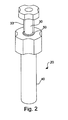
- FIG. 2 depicts a three dimensional front view of the present invention.
- FIG. 3 shows three-dimensional front views of the separate components of the present invention.
- FIG. 4 shows a three dimensional bottom view of the separate components of the present invention.
- FIGS. 5 A, B, C, D, and E show cross sectional views of the separate components of the present invention.
- FIG. 6 depicts a cross sectional view of the invention, as assembled.
- FIG. 7 illustrates how the present invention is used.
- FIGS. 1A and 1B show views of a prior art wick trimmer.
- FIG. 1A shows the wick trimmer 10 , which is an early American antique made of wrought iron.
- FIG. 1B the wick trimmer 10 is placed in base 11 .
- the base 11 is made to complement candlesticks of the period. It can be appreciated that the wick trimmer 10 is shaped like a scissors.
- FIG. 2 shows a three dimensional front view of the wick cutter 20 featured in the invention.
- the wick trimmer 20 is made of injection molded plastic with a hardened steel blade. It should be noted that the wick cutting device can be made of other various sturdy materials.
- the wick trimmer 20 is composed of two parts, a hollow outer cylinder 40 and an inner cylinder 48 that can be inserted inside the outer cylinder 40 .
- the outside cylinder 40 is shorter in length than the inner cylinder 48 .
- the outer cylinder 40 has a grip 70 which is shaped like a gearwheel.
- the outer cylinder 40 has a groove 50 in the top of the cylinder.
- the basic design of the wick cutting device is a tube inside a tube.
- the inner cylinder 48 has a handle 60 at the top, also shaped like a gearwheel.
- a groove 50 is cut in the grip 70 of the outer cylinder 40 in the shape of a letter C, and is adapted to receive hanging wall 33 which extends from handle 60 in which part of the inner cylinder 48 sits.
- FIG. 3 shows a three-dimensional front view of the hollow cylinders taken apart.
- the outer cylinder 40 is shorter than the inner cylinder 48 .
- the outer cylinder 40 is approximately 15 cm and the inner cylinder 48 is approximately 17 cm.
- the groove 50 can be seen surrounding the hole 51 in which the inner cylinder 48 is inserted.
- the groove 50 is shaped like a letter C. Details of the inner cylinder [ 30 ] 48 can be observed in the figure.
- the tube (or cylinder) 48 is inserted inside the hole 51 of the outer cylinder 40 .
- the tube 48 has a pin 32 sticking from the side, this pin 32 fits inside an inner groove or channel 52 in the inside wall of the outer cylinder 40 . When the tube 48 is inserted into the outer cylinder, the pin 32 sits on the inner groove 52 .
- inner cylinder 48 is forced into outer cylinder 40 until pin 32 sits in inner groove 52 by using a suitable press or similar device capable of applying pressure to a workpiece.
- a suitable press or similar device capable of applying pressure to a workpiece.
- This locks the tubes together, allowing free rotational movement of the inner tube 48 inside the outer cylinder 40 .
- the semicircular hanging wall 33 from the top handle. In the most preferred embodiment, the hanging wall 33 is approximately 2 cm long. This hanging wall 33 is inserted in the groove 50 .
- the groove provides the range of twisting allowed for the inner cylinder 48 .
- the inner tube 48 contains the blade 35 that will cut the wick. The cut wick can be removed by the hole 34 in the inner cylinder 48 .
- FIG. 4 shows a three-dimensional bottom view of the hollow cylinders taken apart. Pin 32 and the semicircular hanging wall 33 can be seen.
- the outer diameter of outer cylinder 40 is approximately 2.5 cm; the inner diameter of outer cylinder 40 is approximately 1.8 cm. In the most preferred embodiment, the outer diameter of inner cylinder 48 is approximately 1.7 cm and the inner diameter is 1.2 cm.
- blade 35 can be seen. Blade 35 is attached to plastic section 36 , covering at least half of hole 34 and forming aperture 51 when inner cylinder 48 is placed inside outer cylinder 40 . In a most preferred embodiment, blade 35 is made of hardened steel and is flush with the end of inner cylinder 48 opposite handle 60 .
- a wick cutting device can be made of different colors, including but not limited to, gold, silver, and black.
- semicircular plastic cover 42 covers half of aperture 51 .
- Plastic cover 42 is attached by pin 41 to outer cylinder 40 .
- Plastic cover 42 is fixedly secured to the outer or first cylinder 40 .
- plastic cover 42 is recessed approximately 0.64 cm (1 ⁇ 4 inch) allowing the trimming of the wick to the length recommended most often by the candle industry.
- plastic cover 42 can be removably secured to outer or first cylinder 40 .
- FIGS. 5A, 5 B, 5 C, 5 D and 5 E show cross sectional and top views of the wick trimmer components.
- FIG. 5A shows a top view of the gear wheel handle 60 which is attached to the inner cylinder 48 .
- the hole 34 can be seen and is crossed by the pin 32 .
- the gear wheel is smooth, with soft indentations 38 and teeth 37 .
- the indentations 38 allow for a comfortable fit of the fingers of the hand when holding the wick cutter.
- FIG. 5B shows a top view of the outer cylinder 40 .
- the outer groove 50 in the top of the grip 70 can be observed.
- the grip 70 of the outer cylinder 40 has a height of approximately 3.8 cm as compared to the 1.3 cm height of the handle in the inner cylinder 48 .
- the diameter of both handles is exactly the same, such that when one observes the wick trimmer from the top only one gear wheel can be seen, as shown in FIG. 5 C.
- FIG. 5D shows a cross sectional view of the inner cylinder 48 .
- the pin 32 is located on the body of the inside cylinder 48 such that it will mate with the inner groove 52 of the outer cylinder, as shown in FIG. 5 E.
- FIGS. 5D and 5E depict the other mating components such as the semicircular hanging wall 33 and the C-shaped groove 50 .
- FIG. 6 shows cross sections of the assembled wick trimmer.
- FIG. 6 depicts how pin 32 goes through the hole 34 and sits in the inner groove 52 .
- the semicircle hanging wall 33 is shown sitting in the outside groove 50 .
- the space 43 between the bottoms of the inner and outer cylinder can be noted. This space allows to recede the blade 0.64 cm (or 1 ⁇ 4 inch), the recommended length for candle wicks.
- FIG. 7 shows wick trimmer 20 in use.
- the cylinders forming the wick trimmer 20 are rotated into a position that creates a half circle aperture (as shown in FIG. 4 by aligning the blade 35 over the recessed plastic cover 42 .
- Wick trimmer 20 is put at the top of candle 21 allowing for the introduction of the candle wick (not shown) into aperture 51 (not shown).
- plastic cover 42 is recessed allowing for the recommended length of wick to remain on the candle.
- One hand 22 holds the outer cylinder 40 by the grip 70 while the other hand twists the handle 30 of the inner cylinder 48 . The twisting motion causes blade 35 to push the wick against the plastic cover 42 .
- the groove 50 in combination with wall 33 controls the amount of rotation by limiting over-rotation or twisting of the inner cylinder 48 .
- the wick is then cut by blade 35 to the desired length using plastic cover 42 to hold the wick while it is being cut. Once cut, the sheared wick is captured on the inside of recessed plastic cover 42 , lifted from the candle and later removed from the inside of the inner cylinder 48 . Alternatively, the cut wick may be lifted from the top of candle 21 .
Abstract
Description
Claims (6)
Priority Applications (1)
| Application Number | Priority Date | Filing Date | Title |
|---|---|---|---|
| US09/639,402 US6655031B1 (en) | 2000-08-15 | 2000-08-15 | Wick cutting device |
Applications Claiming Priority (1)
| Application Number | Priority Date | Filing Date | Title |
|---|---|---|---|
| US09/639,402 US6655031B1 (en) | 2000-08-15 | 2000-08-15 | Wick cutting device |
Publications (1)
| Publication Number | Publication Date |
|---|---|
| US6655031B1 true US6655031B1 (en) | 2003-12-02 |
Family
ID=29550398
Family Applications (1)
| Application Number | Title | Priority Date | Filing Date |
|---|---|---|---|
| US09/639,402 Expired - Lifetime US6655031B1 (en) | 2000-08-15 | 2000-08-15 | Wick cutting device |
Country Status (1)
| Country | Link |
|---|---|
| US (1) | US6655031B1 (en) |
Cited By (2)
| Publication number | Priority date | Publication date | Assignee | Title |
|---|---|---|---|---|
| US20050227191A1 (en) * | 2004-04-07 | 2005-10-13 | Feaser Wendy S | Candlewick trimmer |
| US7497684B1 (en) * | 2008-01-10 | 2009-03-03 | Latina Storms | Combination wick cutter and lighter |
Citations (6)
| Publication number | Priority date | Publication date | Assignee | Title |
|---|---|---|---|---|
| US853832A (en) * | 1907-03-12 | 1907-05-14 | Martin M Ryan | Nail-trimming device. |
| US2894324A (en) * | 1958-08-11 | 1959-07-14 | Carl L Hardin | Wire cutter |
| US4844064A (en) * | 1987-09-30 | 1989-07-04 | Baxter Travenol Laboratories, Inc. | Surgical cutting instrument with end and side openings |
| US4850354A (en) * | 1987-08-13 | 1989-07-25 | Baxter Travenol Laboratories, Inc. | Surgical cutting instrument |
| US4914818A (en) * | 1988-08-23 | 1990-04-10 | The United States Of America As Represented By The United States Department Of Energy | Coaxial cable cutter |
| US6209207B1 (en) * | 1999-04-12 | 2001-04-03 | Shannon L. Patterson | Handheld candle wick cutting device |
-
2000
- 2000-08-15 US US09/639,402 patent/US6655031B1/en not_active Expired - Lifetime
Patent Citations (6)
| Publication number | Priority date | Publication date | Assignee | Title |
|---|---|---|---|---|
| US853832A (en) * | 1907-03-12 | 1907-05-14 | Martin M Ryan | Nail-trimming device. |
| US2894324A (en) * | 1958-08-11 | 1959-07-14 | Carl L Hardin | Wire cutter |
| US4850354A (en) * | 1987-08-13 | 1989-07-25 | Baxter Travenol Laboratories, Inc. | Surgical cutting instrument |
| US4844064A (en) * | 1987-09-30 | 1989-07-04 | Baxter Travenol Laboratories, Inc. | Surgical cutting instrument with end and side openings |
| US4914818A (en) * | 1988-08-23 | 1990-04-10 | The United States Of America As Represented By The United States Department Of Energy | Coaxial cable cutter |
| US6209207B1 (en) * | 1999-04-12 | 2001-04-03 | Shannon L. Patterson | Handheld candle wick cutting device |
Cited By (4)
| Publication number | Priority date | Publication date | Assignee | Title |
|---|---|---|---|---|
| US20050227191A1 (en) * | 2004-04-07 | 2005-10-13 | Feaser Wendy S | Candlewick trimmer |
| US20060134570A1 (en) * | 2004-04-07 | 2006-06-22 | Feaser Wendy S | Candlewick trimmer |
| US7104785B2 (en) | 2004-04-07 | 2006-09-12 | Feaser Wendy S | Candlewick trimmer |
| US7497684B1 (en) * | 2008-01-10 | 2009-03-03 | Latina Storms | Combination wick cutter and lighter |
Similar Documents
| Publication | Publication Date | Title |
|---|---|---|
| US20120129114A1 (en) | Candle Wick System | |
| US4389187A (en) | Extended holder for a lighter | |
| US6405441B1 (en) | Wick trimmer and capture device | |
| US6655031B1 (en) | Wick cutting device | |
| US7104785B2 (en) | Candlewick trimmer | |
| US9222057B1 (en) | Precision cutting tool for cutting or trimming pillar candles | |
| US2697927A (en) | Candle holder | |
| US7040888B2 (en) | Smart wick | |
| US6370779B1 (en) | Wick trimmer | |
| US6711821B1 (en) | Heated candle-cutting device | |
| US5537989A (en) | Candle wick extracting and positioning device and method | |
| US3360966A (en) | Extendable wick candle | |
| US20040023177A1 (en) | Device and method for exposing a candle wick embedded in candle wax | |
| US7553154B2 (en) | Candle wick method | |
| US20050039335A1 (en) | Candle wick maintenance instrument | |
| CN109481290B (en) | Special automatic ignition equipment for smokeless moxa stick and using method thereof | |
| US20030134243A1 (en) | Smokeless candle snuffer and wick trimmer combination | |
| WO2015089216A1 (en) | Candle assembly with retracting non-combustible wick | |
| US20080131825A1 (en) | Candle reshaper | |
| CN202037563U (en) | Candlewick clamp | |
| CN2419479Y (en) | Assistant positioner for candle holder | |
| KR200301857Y1 (en) | Candlestick for perfume effect | |
| CN2593780Y (en) | Easily lighted smokeless moxibustion stick | |
| CN2332886Y (en) | Lamp holder device | |
| JP3006617U (en) | Incense burner |
Legal Events
| Date | Code | Title | Description |
|---|---|---|---|
| AS | Assignment |
Owner name: CLIPAWICK, LLC, NEW YORK Free format text: ASSIGNMENT OF ASSIGNORS INTEREST;ASSIGNORS:GRANT, DIANNA;LEVIN, ROBERT;LEVIN, DARLENE;REEL/FRAME:011106/0146 Effective date: 20000802 |
|
| AS | Assignment |
Owner name: GRANT, DIANNA, NEW YORK Free format text: ASSIGNMENT OF ASSIGNORS INTEREST;ASSIGNOR:CLIPAWICK, LLC;REEL/FRAME:014443/0154 Effective date: 20030822 |
|
| STCF | Information on status: patent grant |
Free format text: PATENTED CASE |
|
| FEPP | Fee payment procedure |
Free format text: PAYOR NUMBER ASSIGNED (ORIGINAL EVENT CODE: ASPN); ENTITY STATUS OF PATENT OWNER: MICROENTITY |
|
| FPAY | Fee payment |
Year of fee payment: 4 |
|
| REMI | Maintenance fee reminder mailed | ||
| FPAY | Fee payment |
Year of fee payment: 8 |
|
| SULP | Surcharge for late payment |
Year of fee payment: 7 |
|
| FEPP | Fee payment procedure |
Free format text: PATENT HOLDER CLAIMS MICRO ENTITY STATUS, ENTITY STATUS SET TO MICRO (ORIGINAL EVENT CODE: STOM); ENTITY STATUS OF PATENT OWNER: MICROENTITY |
|
| FPAY | Fee payment |
Year of fee payment: 12 |