US6505037B1 - Data unit detection including antenna diversity - Google Patents
Data unit detection including antenna diversity Download PDFInfo
- Publication number
- US6505037B1 US6505037B1 US09/510,907 US51090700A US6505037B1 US 6505037 B1 US6505037 B1 US 6505037B1 US 51090700 A US51090700 A US 51090700A US 6505037 B1 US6505037 B1 US 6505037B1
- Authority
- US
- United States
- Prior art keywords
- symbol
- antenna
- symbols
- data unit
- energy
- Prior art date
- Legal status (The legal status is an assumption and is not a legal conclusion. Google has not performed a legal analysis and makes no representation as to the accuracy of the status listed.)
- Expired - Lifetime
Links
Images


Classifications
-
- H—ELECTRICITY
- H04—ELECTRIC COMMUNICATION TECHNIQUE
- H04B—TRANSMISSION
- H04B7/00—Radio transmission systems, i.e. using radiation field
- H04B7/02—Diversity systems; Multi-antenna system, i.e. transmission or reception using multiple antennas
- H04B7/04—Diversity systems; Multi-antenna system, i.e. transmission or reception using multiple antennas using two or more spaced independent antennas
- H04B7/08—Diversity systems; Multi-antenna system, i.e. transmission or reception using multiple antennas using two or more spaced independent antennas at the receiving station
- H04B7/0802—Diversity systems; Multi-antenna system, i.e. transmission or reception using multiple antennas using two or more spaced independent antennas at the receiving station using antenna selection
- H04B7/0805—Diversity systems; Multi-antenna system, i.e. transmission or reception using multiple antennas using two or more spaced independent antennas at the receiving station using antenna selection with single receiver and antenna switching
- H04B7/0808—Diversity systems; Multi-antenna system, i.e. transmission or reception using multiple antennas using two or more spaced independent antennas at the receiving station using antenna selection with single receiver and antenna switching comparing all antennas before reception
Definitions
- the present invention relates to a communication system including antenna selection diversity.
- data is transferred in data units that include a header and a data section.
- the data unit may be any general data structure, sometimes referred to as a packet or frame.
- the header of each data unit includes a preamble or OFDM training structure comprising a “short training sequence” followed by a “long training sequence.”
- the “long training sequence” comprises two 3.2 ⁇ s duration symbols. It is to be understood that symbols may be any type of signal, different durations, different amplitudes, different frequencies, and different characteristics, as desired.
- the long training sequence is used for channel and fine frequency offset estimation.
- the short training sequence comprises ten repetitions of a 0.8 ⁇ s duration symbol for a total sequence length of 8 ⁇ s.
- the receiver normally performs signal detection, automatic gain control (AGC), coarse frequency offset determination (CFOD), and timing synchronization.
- the receiving device may perform energy determination and antenna diversity selection.
- a detection circuit of a receiving device converts an analog radio frequency (R/F) signal received at the antenna to a digital signal and determines whether the received signal is sufficiently strong to be recognizable above the noise in the communication system.
- the signal detection circuit senses the presence of a signal.
- the strength of the received R/F signal can vary by orders of magnitude.
- the analog-to-digital (A/D) signal converter of the detector requires a relatively constant amplitude input signal to avoid clipping and loss of message bits.
- AGC automatic gain control
- the transmitting device and the receiving device each include a clock circuit, normally implemented as an oscillator.
- the CFOD circuit synchronizes the frequency of the oscillator in the receiving device to match that of the received signals. In this manner the receiving device adjusts the oscillator to match the actual frequencies of the received symbols.
- the timing synchronization circuit synchronizes the temporal relationship of the oscillator in the receiver to match that of the received signals. In this manner the receiving device determines where each symbol actually starts.
- the resulting wavelength of the signal is on the order of five centimeters.
- the receiving device such as a wireless telephone, may be periodically located in an unsuitable phase relationship with respect to the received signal.
- the receiving device may be positioned at a location where the signal is at a minimum making reception difficult, if at all possible.
- one possible receiving device 20 includes a pair of spaced apart antennas 22 a and 22 b.
- Each of the antennas 22 a and 22 b is interconnected to a respective detection circuit 24 a and 24 b.
- Each of the detection circuits 24 a and 24 b performs signal detection, automatic gain control (AGC), energy determination, coarse frequency offset determination (CFOD), and timing synchronization.
- the energy determination determines which antenna 22 a, 22 b senses the strongest signal, normally using a correlator, and accordingly a switch circuit 26 selects the antenna 22 a, 22 b with the strongest signal to receive the following data unit.
- AGC automatic gain control
- CFOD coarse frequency offset determination
- the present invention overcomes the aforementioned drawbacks of the prior art by providing a system for adjusting a receiving device in response to sensing symbols.
- An automatic gain control is adjusted in response receiving a first symbol of a data unit from a first antenna.
- After adjusting the automatic gain control at least a second and a third symbol of the data unit are received, and in response thereto (1) a first energy of at least one of the second and third symbols is calculated, (2) a first frequency offset of at least one of the second and third symbols is calculated, and (3) a first temporal offset of at least one of the second and third symbols is calculated.
- the automatic gain control in response receiving a fourth symbol of the data unit from a second antenna is calculated.
- At least a fifth and a sixth symbol of the data unit is received, and in response thereto (1) a second energy of at least one of the fifth and sixth symbols is calculated, (2) a second frequency offset of at least one of the fifth and sixth symbols is calculated, and (3) a second temporal offset of at least one of the fifth and sixth symbols is calculated.
- At least one of the first and second antenna is selected based upon a comparison between the first and second energy. In this manner, antenna diversity selection may be performed within a limited duration of available symbols.
- FIG. 1 is a schematic illustration of a receiving device including two detection circuits.
- FIG. 2 is a schematic illustration of a receiving device including one detecting circuit.
- FIG. 3 is a simplified block diagram of a detecting circuit.
- FIG. 4 is a timing diagram for receiving a training sequence.
- FIG. 5 is an exemplary timing diagram of receiving a training sequence in accordance with the present invention.
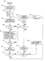
- FIG. 6 is an exemplary flowchart for the training sequence of FIG. 5 .
- a receiving device 30 includes one detecting circuit 32 switched between two or more spaced apart antennas 34 a, 34 b. In this manner the receiving device 30 only requires a single detecting circuit 32 thereby reducing power consumption and expense.
- the P802.11A standard requires the determination of many parameters with the ten short symbols provided during the short training sequence. Referring also to FIGS. 3 and 4, the first symbol is sensed by a detector circuit 36 of the detecting circuit 32 from one of the antennas 32 a, 32 b to sense a data unit. The second symbol sensed by the detector circuit 36 is used by the AGC circuit 38 , as previously described. The AGC circuit 38 may require one or more symbols.
- the third and fourth symbols sensed by the detector circuit 36 are used by the energy determination circuit 40 to measure the signal strength.
- a switch circuit 42 switches to the other antenna 32 a, 32 b during the fifth symbol.
- the sixth symbol is then sensed by the detector circuit 36 .
- the seventh symbol sensed by the detector circuit 36 is used by the AGC circuit 38 .
- the eighth and ninth symbols sensed by the detector circuit 36 are used by the energy determination circuit 40 to measure the signal strength of the other antenna 32 a, 32 b. In this manner, the antenna 32 a, 32 b with the strongest signal is determined for further receipt of the data unit.
- the selection of the proper antenna 32 a, 32 b decreases the data unit loss rate, decreases the total transmission delay, and increases the system throughput.
- the tenth symbol would then need to be used to perform CFOD and timing synchronization in order to determine the necessary calculations with the short training sequence of ten symbols.
- the other antenna 32 a, 32 b has the weaker energy then a symbol duration is required to switch back to the first antenna 32 a, 32 b from which to receive the remaining symbols.
- no additional symbols are available during the short training sequence from which to determine CFOD and timing synchronization if the tenth symbol is used for switching.
- most systems switch between the antennas 32 a, 32 b periodically so the first symbol of the short training sequence may arrive during the switching time. Accordingly, the first symbol detected may be the second or later symbol. Similarly, this limits the available symbols within the short training sequence from which to determine the necessary parameters.
- a false alarm occurs when the presence of a signal is “detected” even though there is no actual signal.
- a false alarm usually sets the detecting circuit into a “busy” mode and starts a sequence of functions (decoding). As this sequence of functions is being performed by the detecting circuit, the detecting circuit may determine that there has been a false alarm and revert back to a “standby” mode. If the detecting circuit has received no data units during the period in which the receiving device is in the “busy” mode, then there will not be any lost data units as a result of the false alarm.
- the detecting circuit might allow the data unit to go undetected thereby contributing to the loss of a data unit. It may be observed that a false alarm potentially contributes to the loss of a data unit if the detecting circuit goes into a mode where no further symbol detection is performed or when the detecting circuit assumes that the long symbol will follow exactly after 10 short symbols. In contrast, the present inventor determined that the detecting circuit should perform continuous monitoring of the channel which will decrease the impact of false alarms. Also, the long symbol transition should be detected independently of the number of short symbols that are detected to further avoid any cost associated with the “busy” mode that originates due to the false alarm.
- the detecting circuit does not need to actually count, or otherwise keep track of, the number of short symbols of the short training sequence. If the long symbol transition goes undetected, then the situation simply becomes another missed data unit detection. With this modification of the detecting circuit the effects of false alarms can be minimized, especially in a receiving device with a short training sequence having a limited number of symbols.
- a data unit is considered lost if the detection of the data unit is missed or if the data unit contains unrecoverable errors.
- the probability of a lost data unit may be represented as (one antenna):
- Pr [a data unit loss] P M +(1 ⁇ P M ) Pr [Frame in error
- P M is the probability of a missed detection.
- Pr the probability of a missed detection.
- Frame is detected] depends on the channel, convolutional coding, and the interleaver.
- a missed detection is considered to occur when the presence of the symbols of the short training sequence are, for example, (1) not detected, (2) not detected early enough so that the necessary functions can be performed with the short symbols received, (3) or when the transition to the long symbols is not detected.
- the functions that should be performed during the short symbol reception are the symbol detection, the AGC, the switching, the diversity selection if there are multiple antennas (energy determination), the CFOD, and the timing synchronization.
- the CFOD and the timing synchronization can only be reasonably performed after the establishment of the AGC. Thus, it is important that the AGC be determined prior to CFOD and timing synchronization. At least two short symbol durations are required to perform CFOD and timing synchronization. Under the assumption that AGC can be performed in one short symbol, while using one antenna, the detecting circuit needs to be able to detect the signal within at least seven short symbols (10 total symbols—[AGC(one symbol)+(CFOD+TS) (two symbols)].
- the probability of a missed detection during a short symbol is about 10 ⁇ 4
- the probability of a missed detection during short symbol is 10 ⁇ 28 in the AWGN channel and 10 ⁇ 14 in a flat fading channel.
- the worst-case scenario of the probability of a missed detection is 10 ⁇ 10 .
- equation (1) may be modified to the following (equation 2):
- Pr [a data unit lost] Pr [missed detection on both antennas]+ Pr [antenna 1 is used for detection] Pr [frame in error
- Equation (2) disregards the effects of false alarms because false alarms are highly unlikely in view of the aforementioned detecting circuit modification.
- the first term of equation (2) is analogous to the first term in equation (1).
- a data unit is deemed missed when the presence of the symbols of the short training sequence are, for example, (1) not detected, (2) not detected early enough so that the necessary functions can be performed with the reception of the short symbols, (3) or when the transition to the long symbols is not detected.
- the functions that need to be performed during the reception of the short symbols should be done in a timely manner.
- the receiver When the receiver is in a standby mode, the receiver will alternate between the two antennas with signal collection on each antenna normally lasting for the duration of one short symbol. This also means that the receiver should wait for one short symbol before it starts detecting the signal (and get ready to perform the associated functions).
- the receiver When a symbol is detected, the receiver needs to as before, three to five symbols to establish the signal (switch, detect, AGC, CFOD, and time synchronization). In either case, there are at least five symbols during which the presence of the signal needs to be detected.
- the probability of a miss by two antennas is the same as for one antenna (nearly zero) and may be disregarded.
- the first multiplicative term in the second additive term in equation (2) (as well as the first multiplicative term in the third additive term) depends on the signal level on the antenna with respect to the signal level on the other antenna and/or the time line. In essence, the antenna with the greatest energy level is selected.
- a pair of symbols are typically used for the detection of the presence of the signal (optional), namely, one symbol (or more) for the first antenna and another symbol (or more) for the second antenna.
- a pair of symbols are used for AGC adjustment, namely one symbol (or more) for the first antenna and another symbol (or more) for the second antenna.
- a pair of symbols (or more) for each antenna are used for energy determination.
- One symbol (or more) is normally used for the switching from one antenna to another.
- At least nine symbols are needed, namely, for detection (two), for AGC (two), for energy determination (four), and for switching (one).
- the additional symbol is useful in the event of switching during the first symbol.
- at least two symbols (or more) for each antenna are used for CFOD and timing synchronization, namely, two symbols for the first antenna and two symbols for the second antenna.
- the present inventor came to the further realization that the CFOD and the timing synchronization may be performed once for each antenna together with the energy determination to alleviate the restrictions imposed by the ten symbols of the short training sequence.
- the preferred technique includes symbol detection by a first antenna, AGC, then the combination of energy determination, CFOD, and timing synchronization. Then the system switches to a second antenna during the subsequent symbol. Then symbol detection, AGC, then the combination of energy determination, CFOD, and timing synchronization is performed with symbols from the second antenna.
- the first symbol may be missed if a switch is performed when it is received.
- the number of short symbols used with the technique of FIG. 5 is nine short symbols, which is less than the ten symbols available. In addition, if the first symbol is missed, then only nine short symbols are used which is still permitted by the P802.11A standard.
- the antenna may be switched to the first antenna if it has greater energy during the last symbol or after the short training sequence. It is to be understood that the determination of the parameters may likewise be performed on buffered signals, if desired, so the order of calculation may differ somewhat. In addition, the symbol detection is optional. Also, the detection and/or determination of the parameters may be done between the symbols, if desired.
- Block 52 switches to antenna A.
- E represents the energy detected by the currently selected antenna.
- E old represents the energy detected by the previously selected antenna.
- F is a flag.
- Block 56 integrates any energy received on the selected antenna (antenna A) during a short symbol duration and stores the result in E. In other words, block 56 senses the presence of a symbol and some measure of its energy.
- Block 58 determines if the received energy in E is less than a first threshold T 1 . If E is less than T 1 then block 60 determines if the flag F is 1.
- E is set to 0 by block 62 and block 64 switches to the other antenna. Setting E to 0 reinitializes the energy detected back to zero.
- the loop of blocks 56 , 58 , 60 , 62 , and 64 alternatively switch between the antennas until sufficient energy is detected indicating a valid data unit at block 58 by E not being less than T 1 .
- Block 72 determines if E is less than a second threshold T 2 , which if true, then the system branches to block 60 . If F is not equal to 1 then E is set to zero and the antenna is switched at block 64 . This is representative of receiving noise or simply insufficient energy to process the rest of the data unit. If block 72 determines that E is not less than a second threshold T 2 , then the system saves the parameters, AGC, E, CFOD, and timing synchronization, at block 74 .
- Block 76 checks to see if F is equal to 1, which if not true, then control is passed to block 78 .
- Block 78 sets F equal to 1 and E old equal to E. Setting F equal to 1 indicates that a first set of symbols from a first antenna has been processed having a sufficient energy and that the other antenna should now be checked. Setting E old equal to E saves the energy determined from the first antenna so that it may be later compared again the energy for the other antenna.
- Block 64 switches to the other antenna and block 56 integrates and saves the resulting value in E. If E (for the other antenna) is less than threshold T 1 then block 58 branches to block 60 , which in turn branches to block 80 . This result indicates that no valid signal was detected on the other antenna. Block 80 switches back to the first antenna which had a valid set of detected symbols. Control is then passed to block 82 for the detection of the subsequent long symbol detection.
Abstract
A system adjusts a receiving device in response to sensing symbols. An automatic gain control is adjusted in response receiving a first symbol of a data unit from a first antenna. After adjusting the automatic gain control at least a second and a third symbol of the data unit are received, and in response thereto (1) a first energy of at least one of the second and third symbols is calculated, (2) a first frequency offset of at least one of the second and third symbols is calculated, and (3) a first temporal offset of at least one of the second and third symbols is calculated. The automatic gain control in response receiving a fourth symbol of the data unit from a second antenna is received. After adjusting the automatic gain control at least a fifth and a sixth symbol of the data unit is calculated, and in response thereto (1) a second energy of at least one of the fifth and sixth symbols is calculated, (2) a second frequency offset of at least one of the fifth and sixth symbols is calculated, and (3) a second temporal offset of at least one of the fifth and sixth symbols is calculated. At least one of the first and second antenna is selected based upon a comparison between the first and second energy. In this manner, antenna diversity selection may be performed within a limited duration of available symbols.
Description
This application claims the benefit of U.S. Provisional Application No. 60/141,419, filed Jun. 29, 1999.
The present invention relates to a communication system including antenna selection diversity.
The Institute of Electrical and Electronic Engineers (IEEE), DRAFT SUPPLEMENT TO STANDARD FOR INFORMATION TECHNOLOGY-TELECOMMUNICATIONS AND INFORMATION EXCHANGE BETWEEN SYSTEMS—LOCAL AND METROPOLITAN AREA NETWORKS—SPECIFIC REQUIREMENTS—PART 11: WIRELESS LAN MEDIUM ACCESS CONTROL (MAC) AND PHYSICAL LAYER (PHY) SPECIFICATIONS: HIGH SPEED PHYSICAL LAYER IN THE 5 GHz BAND, IEEE P802.11A/D7.0, July 1999, is part of a family of standards for wireless Local and Metropolitan Area Networks (hereinafter LAN). The proposed standard specifies certain characteristics of a high speed, digital, wireless communication LAN based on Orthogonal Frequency Division Multiplexing (OFDM) and packet switching, incorporated by reference herein.
In an IEEE 802.11A network, data is transferred in data units that include a header and a data section. The data unit may be any general data structure, sometimes referred to as a packet or frame. The header of each data unit includes a preamble or OFDM training structure comprising a “short training sequence” followed by a “long training sequence.” The “long training sequence” comprises two 3.2 μs duration symbols. It is to be understood that symbols may be any type of signal, different durations, different amplitudes, different frequencies, and different characteristics, as desired. The long training sequence is used for channel and fine frequency offset estimation. The short training sequence comprises ten repetitions of a 0.8 μs duration symbol for a total sequence length of 8 μs. During the short training sequence the receiver normally performs signal detection, automatic gain control (AGC), coarse frequency offset determination (CFOD), and timing synchronization. In addition, the receiving device may perform energy determination and antenna diversity selection.
A detection circuit of a receiving device converts an analog radio frequency (R/F) signal received at the antenna to a digital signal and determines whether the received signal is sufficiently strong to be recognizable above the noise in the communication system. The signal detection circuit senses the presence of a signal. The strength of the received R/F signal can vary by orders of magnitude. On the other hand, the analog-to-digital (A/D) signal converter of the detector requires a relatively constant amplitude input signal to avoid clipping and loss of message bits. Typically, an automatic gain control (AGC) circuit controls the amplitude variation of the R/F signal at the input to the A/D converter while the amplitude of the received R/F signal is varying.
The transmitting device and the receiving device each include a clock circuit, normally implemented as an oscillator. In order to synchronize the frequency relationship of the transmitted and received signals, the CFOD circuit synchronizes the frequency of the oscillator in the receiving device to match that of the received signals. In this manner the receiving device adjusts the oscillator to match the actual frequencies of the received symbols. In order to synchronize the temporal relationship of the transmitted and received signals, the timing synchronization circuit synchronizes the temporal relationship of the oscillator in the receiver to match that of the received signals. In this manner the receiving device determines where each symbol actually starts.
With high transmission frequencies, such as in the range of 5-6 GHz, the resulting wavelength of the signal is on the order of five centimeters. With such a short wavelength the receiving device, such as a wireless telephone, may be periodically located in an unsuitable phase relationship with respect to the received signal. In other words, the receiving device may be positioned at a location where the signal is at a minimum making reception difficult, if at all possible. Accordingly, it is preferable to include multiple antennas interconnected to the same receiving device at spaced apart locations. With multiple spaced apart antennas it is likely that at least one antenna will sense a strong signal. Normally the antenna sensing the strongest signal is selected to receive the following data unit.
Referring to FIG. 1, one possible receiving device 20 includes a pair of spaced apart antennas 22 a and 22 b. Each of the antennas 22 a and 22 b is interconnected to a respective detection circuit 24 a and 24 b. Each of the detection circuits 24 a and 24 b performs signal detection, automatic gain control (AGC), energy determination, coarse frequency offset determination (CFOD), and timing synchronization. The energy determination determines which antenna 22 a, 22 b senses the strongest signal, normally using a correlator, and accordingly a switch circuit 26 selects the antenna 22 a, 22 b with the strongest signal to receive the following data unit. Unfortunately, including a pair of detection circuits 24 a, 24 b within the receiving device 20 consumes twice the power of a single detection circuit and increases the expense of the receiving device 20.
What is desired, therefore, is a receiving device that includes antenna diversity with a single detection circuit, especially a receiving device suitable for a P802.11A.
The present invention overcomes the aforementioned drawbacks of the prior art by providing a system for adjusting a receiving device in response to sensing symbols. An automatic gain control is adjusted in response receiving a first symbol of a data unit from a first antenna. After adjusting the automatic gain control at least a second and a third symbol of the data unit are received, and in response thereto (1) a first energy of at least one of the second and third symbols is calculated, (2) a first frequency offset of at least one of the second and third symbols is calculated, and (3) a first temporal offset of at least one of the second and third symbols is calculated. The automatic gain control in response receiving a fourth symbol of the data unit from a second antenna is calculated. After adjusting the automatic gain control at least a fifth and a sixth symbol of the data unit is received, and in response thereto (1) a second energy of at least one of the fifth and sixth symbols is calculated, (2) a second frequency offset of at least one of the fifth and sixth symbols is calculated, and (3) a second temporal offset of at least one of the fifth and sixth symbols is calculated. At least one of the first and second antenna is selected based upon a comparison between the first and second energy. In this manner, antenna diversity selection may be performed within a limited duration of available symbols.
The foregoing and other objectives, features, and advantages of the invention will be more readily understood upon consideration of the following detailed description of the invention, taken in conjunction with the accompanying drawings.
FIG. 1 is a schematic illustration of a receiving device including two detection circuits.
FIG. 2 is a schematic illustration of a receiving device including one detecting circuit.
FIG. 3 is a simplified block diagram of a detecting circuit.
FIG. 4 is a timing diagram for receiving a training sequence.
FIG. 5 is an exemplary timing diagram of receiving a training sequence in accordance with the present invention.
FIG. 6 is an exemplary flowchart for the training sequence of FIG. 5.
Referring to FIG. 2, a receiving device 30 includes one detecting circuit 32 switched between two or more spaced apart antennas 34 a, 34 b. In this manner the receiving device 30 only requires a single detecting circuit 32 thereby reducing power consumption and expense. The P802.11A standard requires the determination of many parameters with the ten short symbols provided during the short training sequence. Referring also to FIGS. 3 and 4, the first symbol is sensed by a detector circuit 36 of the detecting circuit 32 from one of the antennas 32 a, 32 b to sense a data unit. The second symbol sensed by the detector circuit 36 is used by the AGC circuit 38, as previously described. The AGC circuit 38 may require one or more symbols. The third and fourth symbols sensed by the detector circuit 36 are used by the energy determination circuit 40 to measure the signal strength. Next, a switch circuit 42 switches to the other antenna 32 a, 32 b during the fifth symbol. The sixth symbol is then sensed by the detector circuit 36. The seventh symbol sensed by the detector circuit 36 is used by the AGC circuit 38. The eighth and ninth symbols sensed by the detector circuit 36 are used by the energy determination circuit 40 to measure the signal strength of the other antenna 32 a, 32 b. In this manner, the antenna 32 a, 32 b with the strongest signal is determined for further receipt of the data unit. The selection of the proper antenna 32 a, 32 b decreases the data unit loss rate, decreases the total transmission delay, and increases the system throughput.
The tenth symbol would then need to be used to perform CFOD and timing synchronization in order to determine the necessary calculations with the short training sequence of ten symbols. Unfortunately, it is not possible to perform either the CFOD nor the timing synchronization with a single symbol. In addition, if the other antenna 32 a, 32 b has the weaker energy then a symbol duration is required to switch back to the first antenna 32 a, 32 b from which to receive the remaining symbols. Unfortunately, no additional symbols are available during the short training sequence from which to determine CFOD and timing synchronization if the tenth symbol is used for switching. Also, most systems switch between the antennas 32 a, 32 b periodically so the first symbol of the short training sequence may arrive during the switching time. Accordingly, the first symbol detected may be the second or later symbol. Similarly, this limits the available symbols within the short training sequence from which to determine the necessary parameters.
After consideration of the typical implementations of antenna diversity, one would come to the realization that the designers of the P802.11A standard did not consider the number of symbols necessary during the short training sequence for antenna diversity using a single detector circuit. The apparent solution is to use multiple detection circuits, one for each antenna 32 a, 32 b, or otherwise do not implement antenna diversity.
One event that can result in a loss of a data unit is a false alarm. A false alarm occurs when the presence of a signal is “detected” even though there is no actual signal. A false alarm usually sets the detecting circuit into a “busy” mode and starts a sequence of functions (decoding). As this sequence of functions is being performed by the detecting circuit, the detecting circuit may determine that there has been a false alarm and revert back to a “standby” mode. If the detecting circuit has received no data units during the period in which the receiving device is in the “busy” mode, then there will not be any lost data units as a result of the false alarm. However, if a data unit has been received during the “busy” mode, the detecting circuit might allow the data unit to go undetected thereby contributing to the loss of a data unit. It may be observed that a false alarm potentially contributes to the loss of a data unit if the detecting circuit goes into a mode where no further symbol detection is performed or when the detecting circuit assumes that the long symbol will follow exactly after 10 short symbols. In contrast, the present inventor determined that the detecting circuit should perform continuous monitoring of the channel which will decrease the impact of false alarms. Also, the long symbol transition should be detected independently of the number of short symbols that are detected to further avoid any cost associated with the “busy” mode that originates due to the false alarm. In this manner, the detecting circuit does not need to actually count, or otherwise keep track of, the number of short symbols of the short training sequence. If the long symbol transition goes undetected, then the situation simply becomes another missed data unit detection. With this modification of the detecting circuit the effects of false alarms can be minimized, especially in a receiving device with a short training sequence having a limited number of symbols.
Disregarding the effects of a false alarm, a data unit is considered lost if the detection of the data unit is missed or if the data unit contains unrecoverable errors. Thus, the probability of a lost data unit may be represented as (one antenna):
Pr[a data unit loss]=P M+(1−P M)Pr[Frame in error|Frame is detected] (1)
where PM is the probability of a missed detection. The probability, Pr[Frame in Error|Frame is detected], depends on the channel, convolutional coding, and the interleaver.
A missed detection is considered to occur when the presence of the symbols of the short training sequence are, for example, (1) not detected, (2) not detected early enough so that the necessary functions can be performed with the short symbols received, (3) or when the transition to the long symbols is not detected.
The functions that should be performed during the short symbol reception (either directly or on a buffered signal) are the symbol detection, the AGC, the switching, the diversity selection if there are multiple antennas (energy determination), the CFOD, and the timing synchronization. The CFOD and the timing synchronization can only be reasonably performed after the establishment of the AGC. Thus, it is important that the AGC be determined prior to CFOD and timing synchronization. At least two short symbol durations are required to perform CFOD and timing synchronization. Under the assumption that AGC can be performed in one short symbol, while using one antenna, the detecting circuit needs to be able to detect the signal within at least seven short symbols (10 total symbols—[AGC(one symbol)+(CFOD+TS) (two symbols)]. Assuming a nominal operating signal-to-noise (S/N) ratio of 8 dB in an Additive White Guassian Noise (AWGN) channel, the probability of a missed detection during a short symbol is about 10−4, while in a flat-fading Rayleigh channel, it is about 10−2. Since there are at least 7 short symbols during which the signal needs to be detected, the probability of a missed detection during short symbol is 10−28 in the AWGN channel and 10−14 in a flat fading channel. Even when the gain adjustment is increased to three (presuming AGC takes three symbols to perform) short symbols, the worst-case scenario of the probability of a missed detection is 10−10. Thus, the first term in equation (1) above can be neglected and hence a missed detection is very unlikely to occur in the case of a single antenna and thus can be effectively disregarded.
For the case of multiple antennas, equation (1) may be modified to the following (equation 2):
Note that in equation (2) the last two terms on the right hand side consider the situation in which the signal is detected by only one antenna at a time. Equation (2) disregards the effects of false alarms because false alarms are highly unlikely in view of the aforementioned detecting circuit modification. The first term of equation (2) is analogous to the first term in equation (1). As before, a data unit is deemed missed when the presence of the symbols of the short training sequence are, for example, (1) not detected, (2) not detected early enough so that the necessary functions can be performed with the reception of the short symbols, (3) or when the transition to the long symbols is not detected. In order to minimize the probability of a miss, the functions that need to be performed during the reception of the short symbols should be done in a timely manner. When the receiver is in a standby mode, the receiver will alternate between the two antennas with signal collection on each antenna normally lasting for the duration of one short symbol. This also means that the receiver should wait for one short symbol before it starts detecting the signal (and get ready to perform the associated functions). When a symbol is detected, the receiver needs to as before, three to five symbols to establish the signal (switch, detect, AGC, CFOD, and time synchronization). In either case, there are at least five symbols during which the presence of the signal needs to be detected. Thus, the probability of a miss by two antennas is the same as for one antenna (nearly zero) and may be disregarded. Also, the first multiplicative term in the second additive term in equation (2) (as well as the first multiplicative term in the third additive term) depends on the signal level on the antenna with respect to the signal level on the other antenna and/or the time line. In essence, the antenna with the greatest energy level is selected.
With the establishment that missed detections and false alarms are unlikely, and in general can be disregarded, the present inventor established the requirements desirable for antenna selection diversity with two (or more) antennas. A pair of symbols are typically used for the detection of the presence of the signal (optional), namely, one symbol (or more) for the first antenna and another symbol (or more) for the second antenna. Also, a pair of symbols are used for AGC adjustment, namely one symbol (or more) for the first antenna and another symbol (or more) for the second antenna. In addition, a pair of symbols (or more) for each antenna are used for energy determination. One symbol (or more) is normally used for the switching from one antenna to another. Thus at least nine symbols are needed, namely, for detection (two), for AGC (two), for energy determination (four), and for switching (one). This only leaves one additional symbol which the present inventors determined is not sufficient to perform the CFOD or the timing synchronization, as previously described. The additional symbol is useful in the event of switching during the first symbol. Unfortunately, at least two symbols (or more) for each antenna are used for CFOD and timing synchronization, namely, two symbols for the first antenna and two symbols for the second antenna.
After consideration of the aforementioned timing requirements together with the present inventor's realization of the unlikeliness of false alarms with continuous monitoring and the extremely low probability of missing a data unit, the present inventor came to the further realization that the CFOD and the timing synchronization may be performed once for each antenna together with the energy determination to alleviate the restrictions imposed by the ten symbols of the short training sequence. Referring to FIG. 5, the preferred technique includes symbol detection by a first antenna, AGC, then the combination of energy determination, CFOD, and timing synchronization. Then the system switches to a second antenna during the subsequent symbol. Then symbol detection, AGC, then the combination of energy determination, CFOD, and timing synchronization is performed with symbols from the second antenna. The first symbol may be missed if a switch is performed when it is received. The number of short symbols used with the technique of FIG. 5 is nine short symbols, which is less than the ten symbols available. In addition, if the first symbol is missed, then only nine short symbols are used which is still permitted by the P802.11A standard. If necessary, the antenna may be switched to the first antenna if it has greater energy during the last symbol or after the short training sequence. It is to be understood that the determination of the parameters may likewise be performed on buffered signals, if desired, so the order of calculation may differ somewhat. In addition, the symbol detection is optional. Also, the detection and/or determination of the parameters may be done between the symbols, if desired.
Referring to FIG. 6, a flowchart for implementing the preferred technique includes starting at block 50. Block 52 switches to antenna A. Block 54 sets variables E=0, Eold=0, and F=0. E represents the energy detected by the currently selected antenna. Eold represents the energy detected by the previously selected antenna. F is a flag. Block 56 integrates any energy received on the selected antenna (antenna A) during a short symbol duration and stores the result in E. In other words, block 56 senses the presence of a symbol and some measure of its energy. Block 58 determines if the received energy in E is less than a first threshold T1. If E is less than T1 then block 60 determines if the flag F is 1. If the flag F is not one, then E is set to 0 by block 62 and block 64 switches to the other antenna. Setting E to 0 reinitializes the energy detected back to zero. The loop of blocks 56, 58, 60, 62, and 64 alternatively switch between the antennas until sufficient energy is detected indicating a valid data unit at block 58 by E not being less than T1.
When sufficient energy is detected control is passed from block 58 to block 70 which performs AGC, then collects the signal energy into E, determines the CFOD, and determines the timing synchronization. Block 72 determines if E is less than a second threshold T2, which if true, then the system branches to block 60. If F is not equal to 1 then E is set to zero and the antenna is switched at block 64. This is representative of receiving noise or simply insufficient energy to process the rest of the data unit. If block 72 determines that E is not less than a second threshold T2, then the system saves the parameters, AGC, E, CFOD, and timing synchronization, at block 74. Block 76 checks to see if F is equal to 1, which if not true, then control is passed to block 78. Block 78 sets F equal to 1 and Eold equal to E. Setting F equal to 1 indicates that a first set of symbols from a first antenna has been processed having a sufficient energy and that the other antenna should now be checked. Setting Eold equal to E saves the energy determined from the first antenna so that it may be later compared again the energy for the other antenna.
Now that the system has detected a set of symbols with sufficient energy on the first antenna, the system will check the other antenna. Block 64 switches to the other antenna and block 56 integrates and saves the resulting value in E. If E (for the other antenna) is less than threshold T1 then block 58 branches to block 60, which in turn branches to block 80. This result indicates that no valid signal was detected on the other antenna. Block 80 switches back to the first antenna which had a valid set of detected symbols. Control is then passed to block 82 for the detection of the subsequent long symbol detection.
If E (for the other antenna) is not less than the threshold T1 then block 58 branches to block 70, which performs AGC, energy determination, CFOD, and timing synchronization. If E is less than threshold T2 then insufficient energy was detected for the other antenna and control is passed to block 60. Block 60 then passes control (F=1) to block 80 which switches to the first antenna with the valid data and passes control to block 82 which does long symbol detection. This represents valid data for the first antenna while the data is not sufficient for the other antenna. Accordingly, the first antenna is used for the subsequent data unit.
If E (for the other antenna) is not less than T2 then the parameters, AGC, E, CFOD, and timing synchronization, are saved at block 74 (not over writing the parameters from the first antenna). Block 76 passes control (F=1) to block 84 which determines which antenna has the greater energy. If the currently selected antenna (other antenna) has the greatest energy then control is passed to block 82. If the currently selected antenna (other antenna) does not have the greatest energy then control is passed to block 80 to switch to the first antenna and subsequently to block 82. In this manner the antenna with the greatest energy is selected, all of which is performed within 10 short symbols, or otherwise before valid data is received from the long training sequence.
It is to be understood that the aforementioned techniques may likewise be applied to any other communication system.
The terms and expressions which have been employed in the foregoing specification are used therein as terms of description and not of limitation, and there is no intention, in the use of such terms and expressions, of excluding equivalents of the features shown and described or portions thereof, it being recognized that the scope of the invention is defined and limited only by the claims which follow.
Claims (17)
1. A method of adjusting a receiving device in response to sensing symbols comprising:
(a) adjusting an automatic gain control in response receiving a first symbol of a data unit from a first antenna;
(b) after adjusting said automatic gain control receiving at least a second and a third symbol of said data unit and in response thereto (1) calculating a first energy of at least one of said second and third symbol, (2) calculating a first frequency offset of at least one of said second and third symbol, and (3) calculating a first temporal offset of at least one of said second and third symbol;
(c) adjusting said automatic gain control in response receiving a fourth symbol of said data unit from a second antenna;
(d) after adjusting said automatic gain control receiving at least a fifth and a sixth symbol of said data unit and in response thereto (1) calculating a second energy of at least one of said fifth and sixth symbol, (2) calculating a second frequency offset of at least one of said fifth and sixth symbol, and (3) calculating a second temporal offset of at least one of said fifth and sixth symbol; and
(e) selecting at least one of said first and second antenna based upon a comparison between said first and second energy.
2. The method of claim 1 wherein said automatic gain control is a single automatic gain control circuit.
3. The method of claim 1 wherein said first, second, third, fourth, and fifth symbols are in a non-sequential order.
4. The method of claim 1 wherein said automatic gain control adjusts the amplitude variation of the received symbols at the input to an analog-to-digital converter.
5. The method of claim 1 wherein said first frequency offset and said second frequency offsets are coarse offset frequency determinations.
6. The method of claim 1 wherein said first temporal offset and said second temporal offset are timing synchronization.
7. The method of claim 1 wherein said comparison between said first and second energy is a magnitude determination.
8. The method of claim 1 further comprising sensing an initial symbol from said first antenna prior to said first symbol.
9. The method of claim 8 further comprising sensing an intermediate symbol from said second antenna prior to sensing said fourth symbol and after sensing said third symbol.
10. The method of claim 9 further comprising switching from said first antenna to said second antenna prior to receiving said fourth symbol and after receiving said first symbol.
11. The method of claim 10 wherein said switching occurs during one symbol duration.
12. The method of claim 10 wherein said first symbol, said second symbol, said third symbol, said fourth symbol, said fifth symbol, said sixth symbol, said switching, said initial symbol, and said intermediate symbol occurs within a time duration of nine symbols.
13. The method of claim 12 further comprising switching from said second antenna to said first antenna after receiving said sixth symbol and no later than a tenth symbol of said data unit.
14. The method of claim 8 wherein said sixth symbol is received no later than a tenth symbol of said data unit.
15. The method of claim 9 wherein said sixth symbol is received no later than a tenth symbol of said data unit.
16. The method of claim 10 wherein said sixth symbol is received no later than a tenth symbol of said data unit.
17. The method of claim 12 wherein said sixth symbol is received no later than a tenth symbol of said data unit.
Priority Applications (3)
| Application Number | Priority Date | Filing Date | Title |
|---|---|---|---|
| US09/510,907 US6505037B1 (en) | 1999-06-29 | 2000-02-23 | Data unit detection including antenna diversity |
| US10/337,551 US6856795B2 (en) | 1999-06-29 | 2003-01-06 | Data unit detection including antenna diversity |
| US11/006,855 US7450922B2 (en) | 1999-06-29 | 2004-12-07 | Data unit detection including antenna diversity |
Applications Claiming Priority (2)
| Application Number | Priority Date | Filing Date | Title |
|---|---|---|---|
| US14141999P | 1999-06-29 | 1999-06-29 | |
| US09/510,907 US6505037B1 (en) | 1999-06-29 | 2000-02-23 | Data unit detection including antenna diversity |
Related Child Applications (1)
| Application Number | Title | Priority Date | Filing Date |
|---|---|---|---|
| US10/337,551 Continuation US6856795B2 (en) | 1999-06-29 | 2003-01-06 | Data unit detection including antenna diversity |
Publications (1)
| Publication Number | Publication Date |
|---|---|
| US6505037B1 true US6505037B1 (en) | 2003-01-07 |
Family
ID=26839098
Family Applications (3)
| Application Number | Title | Priority Date | Filing Date |
|---|---|---|---|
| US09/510,907 Expired - Lifetime US6505037B1 (en) | 1999-06-29 | 2000-02-23 | Data unit detection including antenna diversity |
| US10/337,551 Expired - Lifetime US6856795B2 (en) | 1999-06-29 | 2003-01-06 | Data unit detection including antenna diversity |
| US11/006,855 Expired - Fee Related US7450922B2 (en) | 1999-06-29 | 2004-12-07 | Data unit detection including antenna diversity |
Family Applications After (2)
| Application Number | Title | Priority Date | Filing Date |
|---|---|---|---|
| US10/337,551 Expired - Lifetime US6856795B2 (en) | 1999-06-29 | 2003-01-06 | Data unit detection including antenna diversity |
| US11/006,855 Expired - Fee Related US7450922B2 (en) | 1999-06-29 | 2004-12-07 | Data unit detection including antenna diversity |
Country Status (1)
| Country | Link |
|---|---|
| US (3) | US6505037B1 (en) |
Cited By (7)
| Publication number | Priority date | Publication date | Assignee | Title |
|---|---|---|---|---|
| US20020164963A1 (en) * | 2001-04-09 | 2002-11-07 | Tehrani Ardavan Maleki | Method and system for providing antenna diversity |
| US20030153358A1 (en) * | 2002-02-09 | 2003-08-14 | Jaekyun Moon | Apparatus and method for dynamic diversity based upon receiver-side assessment of link quality |
| WO2005112320A2 (en) * | 2004-05-11 | 2005-11-24 | Texas Instruments Incorporated | Orthogonal frequency division multiplex ofdm packet detect unit, method of detecting an ofdm packet |
| US20060034279A1 (en) * | 2004-08-02 | 2006-02-16 | James Cho | Wireless communication using beam forming and diversity |
| US20120071181A1 (en) * | 2009-02-06 | 2012-03-22 | Thomas Licensing | Method for transmission in a wireless network and corresponding method for reception |
| CN102769598A (en) * | 2003-12-29 | 2012-11-07 | 英特尔公司 | Multicarrier receiver with antenna selection and maximum ratio combining |
| US8498368B1 (en) * | 2001-04-11 | 2013-07-30 | Qualcomm Incorporated | Method and system for optimizing gain changes by identifying modulation type and rate |
Families Citing this family (13)
| Publication number | Priority date | Publication date | Assignee | Title |
|---|---|---|---|---|
| US6505037B1 (en) * | 1999-06-29 | 2003-01-07 | Sharp Laboratories Of America, Inc. | Data unit detection including antenna diversity |
| US20030171834A1 (en) * | 2002-03-07 | 2003-09-11 | Silvester Kelan C. | Method and apparatus for connecting a portable media player wirelessly to an automobile entertainment system |
| DE10210238B4 (en) * | 2002-03-08 | 2004-04-22 | Advanced Micro Devices, Inc., Sunnyvale | Switched combination antenna diversity technology |
| DE10241554A1 (en) * | 2002-09-05 | 2004-03-25 | Schleifring Und Apparatebau Gmbh | Digital signal receiver for signal transmission between relatively movable components, e.g. of crane, radar device or computer tomograph, with adjustment of digitizer dependent on measured signal quality |
| JP4090331B2 (en) * | 2002-11-20 | 2008-05-28 | 三洋電機株式会社 | Reception method and apparatus |
| US7321632B2 (en) * | 2003-09-30 | 2008-01-22 | Intel Corporation | Method and apparatus for multi-algorithm detection |
| US6922549B2 (en) * | 2003-10-31 | 2005-07-26 | Cisco Technology, Inc. | Error vector magnitude selection diversity metric for OFDM |
| US8441913B2 (en) * | 2005-09-27 | 2013-05-14 | Qualcomm Incorporated | Switching diversity in broadcast OFDM systems based on multiple receive antennas |
| CN101326743B (en) * | 2005-12-12 | 2013-03-06 | 皇家飞利浦电子股份有限公司 | System, apparatus, and method for multi-band OFDM systems with receiver antenna selection per sub-band |
| US20070259619A1 (en) * | 2006-03-20 | 2007-11-08 | Harris Corporation | Method And Apparatus For Single Input, Multiple Output Selection Diversity Aiding Signal Tracking |
| US7860128B2 (en) * | 2006-06-28 | 2010-12-28 | Samsung Electronics Co., Ltd. | System and method for wireless communication of uncompressed video having a preamble design |
| US8451907B2 (en) * | 2008-09-02 | 2013-05-28 | At&T Intellectual Property I, L.P. | Methods and apparatus to detect transport faults in media presentation systems |
| CN105406195A (en) * | 2015-12-31 | 2016-03-16 | 联想(北京)有限公司 | Frequency adjusting method and electronic apparatus |
Citations (20)
| Publication number | Priority date | Publication date | Assignee | Title |
|---|---|---|---|---|
| US4661902A (en) | 1985-03-21 | 1987-04-28 | Apple Computer, Inc. | Local area network with carrier sense collision avoidance |
| US5029183A (en) | 1989-06-29 | 1991-07-02 | Symbol Technologies, Inc. | Packet data communication network |
| US5231634A (en) | 1991-12-18 | 1993-07-27 | Proxim, Inc. | Medium access protocol for wireless lans |
| US5375140A (en) * | 1992-11-24 | 1994-12-20 | Stanford Telecommunications, Inc. | Wireless direct sequence spread spectrum digital cellular telephone system |
| US5444697A (en) | 1993-08-11 | 1995-08-22 | The University Of British Columbia | Method and apparatus for frame synchronization in mobile OFDM data communication |
| US5572528A (en) | 1995-03-20 | 1996-11-05 | Novell, Inc. | Mobile networking method and apparatus |
| US5682376A (en) | 1994-12-20 | 1997-10-28 | Matsushita Electric Industrial Co., Ltd. | Method of transmitting orthogonal frequency division multiplex signal, and transmitter and receiver employed therefor |
| US5687165A (en) | 1994-10-26 | 1997-11-11 | U.S. Philips Corporation | Transmission system and receiver for orthogonal frequency-division multiplexing signals, having a frequency-synchronization circuit |
| US5694389A (en) | 1995-02-24 | 1997-12-02 | Kabushiki Kaisha Toshiba | OFDM transmission/reception system and transmitting/receiving apparatus |
| US5717689A (en) | 1995-10-10 | 1998-02-10 | Lucent Technologies Inc. | Data link layer protocol for transport of ATM cells over a wireless link |
| US5726973A (en) | 1994-01-18 | 1998-03-10 | Telia Ab | Method and arrangement for synchronization in OFDM modulation |
| US5732113A (en) | 1996-06-20 | 1998-03-24 | Stanford University | Timing and frequency synchronization of OFDM signals |
| US5757766A (en) | 1995-05-31 | 1998-05-26 | Sony Corporation | Transmitter and receiver for orthogonal frequency division multiplexing signal |
| US5787080A (en) | 1996-06-03 | 1998-07-28 | Philips Electronics North America Corporation | Method and apparatus for reservation-based wireless-ATM local area network |
| US5787123A (en) | 1995-10-30 | 1998-07-28 | Sony Corporation | Receiver for orthogonal frequency division multiplexed signals |
| US5812523A (en) | 1995-03-01 | 1998-09-22 | Telia Ab | Method and device for synchronization at OFDM-system |
| US5859842A (en) * | 1994-11-03 | 1999-01-12 | Omnipoint Corporation | Antenna diversity techniques |
| US6014570A (en) * | 1995-12-18 | 2000-01-11 | The Board Of Trustees Of The Leland Stanford Junior University | Efficient radio signal diversity combining using a small set of discrete amplitude and phase weights |
| US6172970B1 (en) * | 1997-05-05 | 2001-01-09 | The Hong Kong University Of Science And Technology | Low-complexity antenna diversity receiver |
| US6330452B1 (en) * | 1998-08-06 | 2001-12-11 | Cell-Loc Inc. | Network-based wireless location system to position AMPs (FDMA) cellular telephones, part I |
Family Cites Families (64)
| Publication number | Priority date | Publication date | Assignee | Title |
|---|---|---|---|---|
| US4070714A (en) * | 1974-02-27 | 1978-01-31 | Monogram Industries, Inc. | Sewerless recirculating toilet and human waste storage system |
| US3909735A (en) * | 1974-04-04 | 1975-09-30 | Ncr Co | Slow switch for bandwidth change in phase-locked loop |
| US3980945A (en) * | 1974-10-07 | 1976-09-14 | Raytheon Company | Digital communications system with immunity to frequency selective fading |
| FR2315809A1 (en) * | 1975-06-24 | 1977-01-21 | Trt Telecom Radio Electr | AUXILIARY SIGNAL TRANSMISSION SYSTEM OF A GROUP OF TELEPHONE CHANNELS OF A FREQUENCY DISTRIBUTED MULTIPLEX |
| US4245325A (en) * | 1978-02-24 | 1981-01-13 | Nippon Telegraph And Telephone Public Corporation | Digital multifrequency signalling receiver |
| JPS5991527A (en) * | 1982-11-17 | 1984-05-26 | Hitachi Ltd | Controlling method of priority of bus |
| GB2148669A (en) * | 1983-10-21 | 1985-05-30 | Philips Electronic Associated | Data receiver |
| US4660215A (en) * | 1983-12-07 | 1987-04-21 | Matsushita Electric Industrial Co., Ltd. | Transmitter/receiver system |
| US4541850A (en) * | 1984-07-02 | 1985-09-17 | Conoco Inc. | Slurry input device |
| US5063547A (en) * | 1984-07-02 | 1991-11-05 | U.S. Philips Corporation | Apparatus for automatically reproducing a user-defined preferred selection from a record carrier |
| JP2556831B2 (en) * | 1985-05-11 | 1996-11-27 | オリンパス光学工業株式会社 | Optical low pass filter and image pickup apparatus using the same |
| US4882619A (en) * | 1986-04-07 | 1989-11-21 | Olympus Optical Co., Ltd. | High resolution image pickup system with color dispersion means |
| ATE91368T1 (en) * | 1986-10-21 | 1993-07-15 | Motorola Inc | RADIO COMMUNICATIONS RECEIVER WITH CIRCUIT ARRANGEMENT FOR CHANGING THE RECEIVER'S BIT RATE. |
| FR2609228B1 (en) * | 1986-12-24 | 1989-12-01 | France Etat | METHOD OF DIGITAL BROADCASTING IN TELEVISION CHANNELS |
| GB8713043D0 (en) * | 1987-06-03 | 1987-07-08 | British Telecomm | Optical switch |
| US4773085A (en) * | 1987-06-12 | 1988-09-20 | Bell Communications Research, Inc. | Phase and frequency detector circuits |
| US5086426A (en) * | 1987-12-23 | 1992-02-04 | Hitachi, Ltd. | Communication network system having a plurality of different protocal LAN's |
| US5012469A (en) * | 1988-07-29 | 1991-04-30 | Karamvir Sardana | Adaptive hybrid multiple access protocols |
| US4910794A (en) * | 1988-08-04 | 1990-03-20 | Norand Corporation | Mobile radio data communication system and method |
| US5070536A (en) * | 1988-08-04 | 1991-12-03 | Norand Corporation | Mobile radio data communication system and method |
| US5191576A (en) * | 1988-11-18 | 1993-03-02 | L'Etat Francais and Telediffusion de France S.A. | Method for broadcasting of digital data, notably for radio broadcasting at high throughput rate towards mobile receivers, with time frequency interlacing and analog synchronization |
| US5134630A (en) * | 1989-04-12 | 1992-07-28 | National Research Development Corporation | Method and apparatus for transparent tone-in-band transmitter, receiver and system processing |
| DE3918357C1 (en) * | 1989-06-06 | 1990-11-29 | Thorsten 4424 Stadtlohn De Erning | |
| FR2658017B1 (en) * | 1990-02-06 | 1992-06-05 | France Etat | METHOD FOR BROADCASTING DIGITAL DATA, ESPECIALLY FOR BROADBAND BROADCASTING TO MOBILES, WITH TIME-FREQUENCY INTERLACING AND ASSISTING THE ACQUISITION OF AUTOMATIC FREQUENCY CONTROL, AND CORRESPONDING RECEIVER. |
| US5063574A (en) * | 1990-03-06 | 1991-11-05 | Moose Paul H | Multi-frequency differentially encoded digital communication for high data rate transmission through unequalized channels |
| FR2660131B1 (en) * | 1990-03-23 | 1992-06-19 | France Etat | DEVICE FOR TRANSMITTING DIGITAL DATA WITH AT LEAST TWO LEVELS OF PROTECTION, AND CORRESPONDING RECEPTION DEVICE. |
| GB9020170D0 (en) * | 1990-09-14 | 1990-10-24 | Indep Broadcasting Authority | Orthogonal frequency division multiplexing |
| WO1991015925A1 (en) * | 1990-03-30 | 1991-10-17 | National Transcommunications Limited | Transmission and reception in a hostile interference environment |
| FR2660448B1 (en) * | 1990-04-03 | 1992-06-05 | Thomson Csf | DEVICE FOR PROJECTING IMAGES. |
| US5077753A (en) * | 1990-04-09 | 1991-12-31 | Proxim, Inc. | Radio communication system using spread spectrum techniques |
| US5136580A (en) * | 1990-05-16 | 1992-08-04 | Microcom Systems, Inc. | Apparatus and method for learning and filtering destination and source addresses in a local area network system |
| US5179555A (en) * | 1990-09-11 | 1993-01-12 | Microcom Systems, Inc. | High speed data compression and transmission for wide area network connections in LAN/bridging applications |
| US5201071A (en) * | 1990-09-26 | 1993-04-06 | Rockwell International Corporation | Method and apparatus for reducing the peak envelope voltage of an RF transmitter while maintaining signal average power |
| US5283780A (en) * | 1990-10-18 | 1994-02-01 | Stanford Telecommunications, Inc. | Digital audio broadcasting system |
| FR2670062B1 (en) * | 1990-11-30 | 1993-11-12 | Thomson Csf | METHOD FOR RECALARING THE LOCAL OSCILLATORS OF A RECEIVER AND DEVICE FOR CARRYING OUT THE METHOD. |
| US5210770A (en) * | 1991-09-27 | 1993-05-11 | Lockheed Missiles & Space Company, Inc. | Multiple-signal spread-spectrum transceiver |
| US5267271A (en) * | 1991-09-27 | 1993-11-30 | Lockheed Missiles & Space Company, Inc. | Signal analysis technique for determining a subject of binary sequences most likely to have been transmitted in a multi-node communication network |
| US5160900A (en) * | 1992-01-21 | 1992-11-03 | Nokia Mobile Phones Ltd. | Method to speed up the training of a shift oscillator in a frequency synthesizer |
| JP2904986B2 (en) * | 1992-01-31 | 1999-06-14 | 日本放送協会 | Orthogonal frequency division multiplex digital signal transmitter and receiver |
| JP3380913B2 (en) * | 1992-06-11 | 2003-02-24 | ソニー株式会社 | Solid-state imaging device |
| FR2693861A1 (en) * | 1992-07-16 | 1994-01-21 | Philips Electronique Lab | Multiplexed orthogonal frequency division signal receiver with frequency synchronization device. |
| US5764287A (en) * | 1992-08-31 | 1998-06-09 | Canon Kabushiki Kaisha | Image pickup apparatus with automatic selection of gamma correction valve |
| US5209183A (en) * | 1992-10-08 | 1993-05-11 | Grain Belt Supply, Inc. | Portable feeder apparatus |
| AU666411B2 (en) * | 1992-11-27 | 1996-02-08 | Commonwealth Scientific And Industrial Research Organisation | A wireless LAN |
| DE69406151T2 (en) * | 1993-01-13 | 1998-04-02 | Koninkl Philips Electronics Nv | Device for synchronizing a local bearer, in OFDM systems |
| US5343498A (en) * | 1993-03-08 | 1994-08-30 | General Electric Company | Sample timing selection and frequency offset correction for U.S. digital cellular mobile receivers |
| KR950008661B1 (en) * | 1993-05-20 | 1995-08-04 | 현대전자산업주식회사 | Bus multiplexing apparatus |
| JPH06338873A (en) * | 1993-05-28 | 1994-12-06 | Canon Inc | Code division multiple communication device |
| SE500986C2 (en) * | 1993-07-20 | 1994-10-17 | Telia Ab | Method and apparatus for synchronization in digital transmission system of type OFDM |
| JPH0746217A (en) * | 1993-07-26 | 1995-02-14 | Sony Corp | Digital demodulator |
| JPH0746218A (en) * | 1993-07-28 | 1995-02-14 | Sony Corp | Digital demodulator |
| US5675572A (en) * | 1993-07-28 | 1997-10-07 | Sony Corporation | Orthogonal frequency division multiplex modulation apparatus and orthogonal frequency division multiplex demodulation apparatus |
| US5446736A (en) * | 1993-10-07 | 1995-08-29 | Ast Research, Inc. | Method and apparatus for connecting a node to a wireless network using a standard protocol |
| US5412687A (en) * | 1993-10-15 | 1995-05-02 | Proxim Incorporated | Digital communications equipment using differential quaternary frequency shift keying |
| JP3041175B2 (en) * | 1993-11-12 | 2000-05-15 | 株式会社東芝 | OFDM synchronous demodulation circuit |
| JP3074103B2 (en) * | 1993-11-16 | 2000-08-07 | 株式会社東芝 | OFDM synchronous demodulation circuit |
| US5490153A (en) * | 1994-08-04 | 1996-02-06 | International Business Machines Corporation | Recovery of lost frames in a communication link |
| US5583859A (en) * | 1994-08-30 | 1996-12-10 | Bell Communications Research, Inc. | Data labeling technique for high performance protocol processing |
| GB9418514D0 (en) * | 1994-09-14 | 1994-11-02 | At & T Global Inf Solution | Information transmission system |
| US5648958A (en) * | 1995-04-05 | 1997-07-15 | Gte Laboratories Incorporated | System and method for controlling access to a shared channel for cell transmission in shared media networks |
| US5682266A (en) * | 1995-04-05 | 1997-10-28 | Eastman Kodak Company | Blur filter for eliminating aliasing in electrically sampled images |
| US5684293A (en) * | 1995-11-29 | 1997-11-04 | Eastman Kodak Company | Anti-aliasing low-pass blur filter for reducing artifacts in imaging apparatus |
| US5834761A (en) * | 1996-03-22 | 1998-11-10 | Sharp Kabushiki Kaisah | Image input apparatus having a spatial filter controller |
| US6505037B1 (en) * | 1999-06-29 | 2003-01-07 | Sharp Laboratories Of America, Inc. | Data unit detection including antenna diversity |
-
2000
- 2000-02-23 US US09/510,907 patent/US6505037B1/en not_active Expired - Lifetime
-
2003
- 2003-01-06 US US10/337,551 patent/US6856795B2/en not_active Expired - Lifetime
-
2004
- 2004-12-07 US US11/006,855 patent/US7450922B2/en not_active Expired - Fee Related
Patent Citations (21)
| Publication number | Priority date | Publication date | Assignee | Title |
|---|---|---|---|---|
| US4661902A (en) | 1985-03-21 | 1987-04-28 | Apple Computer, Inc. | Local area network with carrier sense collision avoidance |
| US5029183A (en) | 1989-06-29 | 1991-07-02 | Symbol Technologies, Inc. | Packet data communication network |
| US5231634A (en) | 1991-12-18 | 1993-07-27 | Proxim, Inc. | Medium access protocol for wireless lans |
| US5231634B1 (en) | 1991-12-18 | 1996-04-02 | Proxim Inc | Medium access protocol for wireless lans |
| US5375140A (en) * | 1992-11-24 | 1994-12-20 | Stanford Telecommunications, Inc. | Wireless direct sequence spread spectrum digital cellular telephone system |
| US5444697A (en) | 1993-08-11 | 1995-08-22 | The University Of British Columbia | Method and apparatus for frame synchronization in mobile OFDM data communication |
| US5726973A (en) | 1994-01-18 | 1998-03-10 | Telia Ab | Method and arrangement for synchronization in OFDM modulation |
| US5687165A (en) | 1994-10-26 | 1997-11-11 | U.S. Philips Corporation | Transmission system and receiver for orthogonal frequency-division multiplexing signals, having a frequency-synchronization circuit |
| US5859842A (en) * | 1994-11-03 | 1999-01-12 | Omnipoint Corporation | Antenna diversity techniques |
| US5682376A (en) | 1994-12-20 | 1997-10-28 | Matsushita Electric Industrial Co., Ltd. | Method of transmitting orthogonal frequency division multiplex signal, and transmitter and receiver employed therefor |
| US5694389A (en) | 1995-02-24 | 1997-12-02 | Kabushiki Kaisha Toshiba | OFDM transmission/reception system and transmitting/receiving apparatus |
| US5812523A (en) | 1995-03-01 | 1998-09-22 | Telia Ab | Method and device for synchronization at OFDM-system |
| US5572528A (en) | 1995-03-20 | 1996-11-05 | Novell, Inc. | Mobile networking method and apparatus |
| US5757766A (en) | 1995-05-31 | 1998-05-26 | Sony Corporation | Transmitter and receiver for orthogonal frequency division multiplexing signal |
| US5717689A (en) | 1995-10-10 | 1998-02-10 | Lucent Technologies Inc. | Data link layer protocol for transport of ATM cells over a wireless link |
| US5787123A (en) | 1995-10-30 | 1998-07-28 | Sony Corporation | Receiver for orthogonal frequency division multiplexed signals |
| US6014570A (en) * | 1995-12-18 | 2000-01-11 | The Board Of Trustees Of The Leland Stanford Junior University | Efficient radio signal diversity combining using a small set of discrete amplitude and phase weights |
| US5787080A (en) | 1996-06-03 | 1998-07-28 | Philips Electronics North America Corporation | Method and apparatus for reservation-based wireless-ATM local area network |
| US5732113A (en) | 1996-06-20 | 1998-03-24 | Stanford University | Timing and frequency synchronization of OFDM signals |
| US6172970B1 (en) * | 1997-05-05 | 2001-01-09 | The Hong Kong University Of Science And Technology | Low-complexity antenna diversity receiver |
| US6330452B1 (en) * | 1998-08-06 | 2001-12-11 | Cell-Loc Inc. | Network-based wireless location system to position AMPs (FDMA) cellular telephones, part I |
Cited By (20)
| Publication number | Priority date | Publication date | Assignee | Title |
|---|---|---|---|---|
| US6961545B2 (en) * | 2001-04-09 | 2005-11-01 | Atheros Communications, Inc. | Method and system for providing antenna diversity |
| US20020164963A1 (en) * | 2001-04-09 | 2002-11-07 | Tehrani Ardavan Maleki | Method and system for providing antenna diversity |
| US8498368B1 (en) * | 2001-04-11 | 2013-07-30 | Qualcomm Incorporated | Method and system for optimizing gain changes by identifying modulation type and rate |
| US7146134B2 (en) | 2002-02-09 | 2006-12-05 | Dsp Group Inc. | Apparatus and method for dynamic diversity based upon receiver-side assessment of link quality |
| US20030153358A1 (en) * | 2002-02-09 | 2003-08-14 | Jaekyun Moon | Apparatus and method for dynamic diversity based upon receiver-side assessment of link quality |
| WO2003069771A1 (en) * | 2002-02-09 | 2003-08-21 | Bermai, Inc. | Apparatus and method for dynamic diversity based upon receiver-side assessment of link quality |
| US7610019B2 (en) | 2002-02-09 | 2009-10-27 | Dsp Group Inc. | Apparatus and method for dynamic diversity based upon receiver-side assessment of link quality |
| US20060258304A1 (en) * | 2002-02-09 | 2006-11-16 | Dsp Group Inc. | Apparatus and method for dynamic diversity based upon receiver-side assessment of link quality |
| CN102769598A (en) * | 2003-12-29 | 2012-11-07 | 英特尔公司 | Multicarrier receiver with antenna selection and maximum ratio combining |
| US20050265219A1 (en) * | 2004-05-11 | 2005-12-01 | Texas Instruments Incorporated | Orthogonal frequency division multiplex (OFDM) packet detect unit, method of detecting an OFDM packet and OFDM receiver employing the same |
| WO2005112320A3 (en) * | 2004-05-11 | 2006-03-02 | Texas Instruments Inc | Orthogonal frequency division multiplex ofdm packet detect unit, method of detecting an ofdm packet |
| WO2005112320A2 (en) * | 2004-05-11 | 2005-11-24 | Texas Instruments Incorporated | Orthogonal frequency division multiplex ofdm packet detect unit, method of detecting an ofdm packet |
| US7525926B2 (en) | 2004-08-02 | 2009-04-28 | Atheros Communications, Inc. | Wireless communication using beam forming and diversity |
| US20090175383A1 (en) * | 2004-08-02 | 2009-07-09 | James Cho | Wireless Communication Using Beam Forming And Diversity |
| US8159967B2 (en) | 2004-08-02 | 2012-04-17 | Qualcomm Atheros, Inc. | Wireless communication using beam forming and diversity |
| US20060034279A1 (en) * | 2004-08-02 | 2006-02-16 | James Cho | Wireless communication using beam forming and diversity |
| US9054766B2 (en) | 2004-08-02 | 2015-06-09 | Qualcomm Incorporated | Wireless communication using beam forming and diversity |
| US20120071181A1 (en) * | 2009-02-06 | 2012-03-22 | Thomas Licensing | Method for transmission in a wireless network and corresponding method for reception |
| US9173182B2 (en) * | 2009-02-06 | 2015-10-27 | Thomson Licensing | Transmission method in a wireless network and corresponding reception method |
| US10117202B2 (en) | 2009-02-06 | 2018-10-30 | Thomson Licensing | Method for reception in a wireless network and corresponding device for reception |
Also Published As
| Publication number | Publication date |
|---|---|
| US20050096001A1 (en) | 2005-05-05 |
| US20030100282A1 (en) | 2003-05-29 |
| US7450922B2 (en) | 2008-11-11 |
| US6856795B2 (en) | 2005-02-15 |
Similar Documents
| Publication | Publication Date | Title |
|---|---|---|
| US6505037B1 (en) | Data unit detection including antenna diversity | |
| US8014270B2 (en) | Wireless receiver for sorting packets | |
| EP1191730B1 (en) | Communication system and method with variable training means | |
| US6032033A (en) | Preamble based selection diversity in a time division multiple access radio system using digital demodulation | |
| US8000379B2 (en) | Radio communication apparatus | |
| US8295380B2 (en) | Automatic gain control circuit for MIMO OFDM receiver | |
| US7450533B2 (en) | Wireless transmitting device and wireless receiving device | |
| KR101121270B1 (en) | Methods and apparatus for parametric estimation in a multiple antenna communication system | |
| EP1286481B1 (en) | Base station apparatus and radio communication method | |
| US20050254608A1 (en) | Method and apparatus for antenna diversity | |
| US6721550B1 (en) | Diversity receiver | |
| DE60211217D1 (en) | TIME DIVERSITY COMBINATION TO INCREASE THE RELIABILITY OF IEEE 802.11 WLAN RECEIVERS | |
| WO2002001887A2 (en) | Method for synchronizing a mobile station to umts while operating in gsm dedicated mode | |
| US7257112B2 (en) | Receiver directed power management for WLAN receiver | |
| US7366139B2 (en) | Switched combining antenna diversity technique | |
| WO2012028917A1 (en) | Antenna-switchable reception system and wireless communications device including same | |
| US7136436B2 (en) | Boundary detection using multiple correlations | |
| JP5842111B2 (en) | Antenna switching reception system | |
| US5983111A (en) | Adaptive constant false alarm rate system for detecting CDPD bursts | |
| JP2004032518A (en) | Diversity receiving method and reception apparatus | |
| US7263147B2 (en) | Low bit error rate antenna switch for wireless communications | |
| US20030099314A1 (en) | Boundary detection using multiple correlations | |
| JP2005168008A (en) | Diversity switch combiner, receiver system provided with diversity switch combiner, and operating method for wideband receiver | |
| JPH0666722B2 (en) | Diversity reception method in mobile station | |
| AU722428B2 (en) | Method of reception timing control |
Legal Events
| Date | Code | Title | Description |
|---|---|---|---|
| AS | Assignment |
Owner name: SHARP LABORATORIES OF AMERICA, INC., WASHINGTON Free format text: ASSIGNMENT OF ASSIGNORS INTEREST;ASSIGNOR:SRINIVAS, KANDALA;REEL/FRAME:010590/0769 Effective date: 20000216 |
|
| STCF | Information on status: patent grant |
Free format text: PATENTED CASE |
|
| FPAY | Fee payment |
Year of fee payment: 4 |
|
| FPAY | Fee payment |
Year of fee payment: 8 |
|
| FPAY | Fee payment |
Year of fee payment: 12 |