US6503261B1 - Bi-directional atherectomy burr - Google Patents
Bi-directional atherectomy burr Download PDFInfo
- Publication number
- US6503261B1 US6503261B1 US09/765,126 US76512601A US6503261B1 US 6503261 B1 US6503261 B1 US 6503261B1 US 76512601 A US76512601 A US 76512601A US 6503261 B1 US6503261 B1 US 6503261B1
- Authority
- US
- United States
- Prior art keywords
- burr
- vessel
- rotated
- blades
- cutting
- Prior art date
- Legal status (The legal status is an assumption and is not a legal conclusion. Google has not performed a legal analysis and makes no representation as to the accuracy of the status listed.)
- Expired - Fee Related
Links
Images

Classifications
-
- A—HUMAN NECESSITIES
- A61—MEDICAL OR VETERINARY SCIENCE; HYGIENE
- A61B—DIAGNOSIS; SURGERY; IDENTIFICATION
- A61B17/00—Surgical instruments, devices or methods, e.g. tourniquets
- A61B17/32—Surgical cutting instruments
- A61B17/3205—Excision instruments
- A61B17/3207—Atherectomy devices working by cutting or abrading; Similar devices specially adapted for non-vascular obstructions
- A61B17/320758—Atherectomy devices working by cutting or abrading; Similar devices specially adapted for non-vascular obstructions with a rotating cutting instrument, e.g. motor driven
-
- A—HUMAN NECESSITIES
- A61—MEDICAL OR VETERINARY SCIENCE; HYGIENE
- A61B—DIAGNOSIS; SURGERY; IDENTIFICATION
- A61B17/00—Surgical instruments, devices or methods, e.g. tourniquets
- A61B17/32—Surgical cutting instruments
- A61B2017/320004—Surgical cutting instruments abrasive
Definitions
- the present invention relates to medical devices in general, and in particular to atherectomy devices for removing deposits from a vessel.
- Atherectomy burrs are becoming commonly used medical devices that remove deposits from a patient's vessel.
- a typical atherectomy device includes a driveshaft that is rotated by a gas turbine or electric motor and has an atherectomy burr disposed at its distal end.
- the atherectomy burr is typically an ellipsoidally shaped metal bead having an abrasive outer coating.
- the coating which usually comprises a diamond grit, removes deposits from a vessel when the burr is rotated at high speed and advanced into the deposits or an occlusion.
- an atherectomy device provides a minimally invasive technique for removing deposits from a vessel
- SVGs saphenous vein grafts
- deposits tend to be loosely calcified and friable and can break up into large pieces before a high-speed atherectomy burr can disintegrate them.
- These lesions are also often covered with a fibrous cap, which is tough and flexible enough to resist disintegration by a high speed cutting burr. Therefore, these types of lesions often require ablation with a less differentially cutting low speed cutter.
- the anastomosis, or entry point, into the vein graft is often highly angulated and surrounded by scar tissue which is more suitable for removal with a more differentially cutting high speed cutting burr. Therefore, in order to perform an atherectomy procedure in an SVG, multiple cutting burrs must be employed, thereby adding to the expense and time required to perform the procedure.
- the present invention is a bi-directional atherectomy device that includes a source of rotational motion and a driveshaft coupled to the source of rotational motion.
- An atherectomy burr at the distal end of the driveshaft has a number of cutting blades having a less aggressive cutting action when rotated in a first direction and a more aggressive cutting action when rotated in a second direction.
- the number of cutting blades have an abrasive surface that is substantially parallel to the outer surface of the burr and a cutting surface that is substantially perpendicular to the outer surface of the burr.
- the less aggressive, abrasive surface removes deposits from a vessel.
- the more aggressive, cutting surface removes deposits from the vessel.
- the one or more blades are parallel to the longitudinal axis of the burr. In another embodiment of the invention, the one or more cutting blades are spiraled along the length of the burr body.
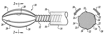
- FIGS. 1 and 2 illustrate an atherectomy burr according to a first embodiment of the present invention
- FIGS. 3 and 4 illustrate an atherectomy burr according to another embodiment of the present invention.
- FIG. 1 illustrates an atherectomy burr constructed in accordance with one embodiment of the present invention.
- the atherectomy burr 10 is secured to the distal end of a driveshaft 12 that is in turn rotated by a source of bi-directional rotation, such as a series of turbines or an electric motor (not shown).
- the driveshaft is routed through a guide catheter 14 that may include one or more additional lumens 16 , 18 . These additional lumens may be used to infuse liquids to an ablation site, or for aspirating debris removed from a vessel.
- the driveshaft 12 and atherectomy burr 10 may include a central lumen such that the atherectomy burr and driveshaft can be routed over a conventional guide wire.
- the ablation burr 10 includes a number of cutting blades 20 that have a less aggressive and more aggressive cutting surface.
- Each cutting blade 20 has a first edge 22 that is generally tangential to the outer surface of the ablation burr.
- Each cutting blade 20 also includes a second cutting edge 24 that is substantially perpendicular to the outer surface of the ablation burr.
- the first edges 22 are preferably covered with an abrasive material such as diamond chips, etc., that constitute a relatively less aggressive cutting surface.
- the transition between the first edge 22 and the second edge 24 forms a more aggressive cutting surface.
- the burr When viewed in cross section as shown in FIG. 2, the burr has a ratchet configuration with each cutting blade 20 ramping radially outward to the point where the first edge 22 meets the second cutting edge 24 in a pattern that continues around the circumference of the burr.
- the abrasive-covered edges 22 engage deposits or an occlusion within a blood vessel and ablate it.
- the particles removed from the blood vessel are sufficiently small such that they can be washed by blood flow downstream of the burr and dissipated by the body.
- the ablation burr is rotated in the direction of the arrow 32
- the second set of edges 24 engage the deposits or occluding material and remove it from a vessel.
- the second set of edges 24 are drawn over the tissue but do not engage it. Because the second set of edges 24 are more aggressive than the first set of edges 22 , aspiration is usually provided through the catheter 14 in order to remove ablated material from the vessel.
- the blades 20 are shown as extending along the length of the burr 10 in FIG. 1, it will be appreciated that the blades could extend less than the entire length of the burr. For example, it may be advisable to provide the burr with an atraumatic distal tip or proximal tail thereby requiring the length of the blades to be less than the entire length of the burr.
- FIG. 3 illustrates an alternative embodiment of the atherectomy burr shown in FIG. 1 .
- an atherectomy burr 40 includes a number of cutting blades 42 that are spiraled along a length of the burr.
- each of the blades 42 includes a first abrasive edge 44 that is generally parallel to the outer surface of the burr and a second cutting edge 46 that is generally perpendicular to the outer surface of the burr.
- the spiraled cutting blades 42 operate to move ablated material proximally when the burr is rotated in the proper direction.
- the spirals are oriented such that the ablated material is moved proximally when the more aggressive cutting blades are used to remove deposits because the more aggressive cutting blades will tend to remove larger pieces of occluding matter.
- aspiration may also be applied to the surrounding catheter.
- the present invention provides a single atherectomy burr that can be used to ablate different types of deposits in a vessel.
- the less aggressive cutting blades can be used to remove harder scar tissue that forms at an anastomosis at the entrance of an SVG.
- the burr can be rotated to utilize the more aggressive cutting blades in order to -cut through the fibrous cap that covers a lesion. Thereafter, cutting can continue with the more aggressive cutting blades to remove the underlying occluding matter within the vessel.
- aspiration can be applied to the catheter to prevent the ablated particles from flowing distally within the vessel.
- the cutting rate and/or cutting characteristics of the burr can be selected by the physician in order to use a single burr to ablate a greater number of tissue types.
- the burr may also be designed to provide no ablation in one direction of rotation and ablation in the other direction.
- the non-ablating direction of rotation would be engaged while the physician accesses the treatment site. It is easier to move the burr past an anastomosis or tortuous section while the burr is spinning due to the orthogonal displacement of friction.
- This burr could be shaped like the burrs in FIGS. 1 and 2 or FIGS. 3 and 4, but have no abrasive coating on the outer surface.
Abstract
Description
Claims (9)
Priority Applications (1)
| Application Number | Priority Date | Filing Date | Title |
|---|---|---|---|
| US09/765,126 US6503261B1 (en) | 2001-01-17 | 2001-01-17 | Bi-directional atherectomy burr |
Applications Claiming Priority (1)
| Application Number | Priority Date | Filing Date | Title |
|---|---|---|---|
| US09/765,126 US6503261B1 (en) | 2001-01-17 | 2001-01-17 | Bi-directional atherectomy burr |
Publications (1)
| Publication Number | Publication Date |
|---|---|
| US6503261B1 true US6503261B1 (en) | 2003-01-07 |
Family
ID=25072715
Family Applications (1)
| Application Number | Title | Priority Date | Filing Date |
|---|---|---|---|
| US09/765,126 Expired - Fee Related US6503261B1 (en) | 2001-01-17 | 2001-01-17 | Bi-directional atherectomy burr |
Country Status (1)
| Country | Link |
|---|---|
| US (1) | US6503261B1 (en) |
Cited By (63)
| Publication number | Priority date | Publication date | Assignee | Title |
|---|---|---|---|---|
| US20040006358A1 (en) * | 2000-04-05 | 2004-01-08 | Pathway Medical Technologies, Inc. | Intralumenal material removal using a cutting device for differential cutting |
| US6818001B2 (en) * | 2000-04-05 | 2004-11-16 | Pathway Medical Technologies, Inc. | Intralumenal material removal systems and methods |
| WO2004080345A3 (en) * | 2003-03-10 | 2005-01-06 | Pathway Medical Technologies I | Interventional catheters having differential cutting surfaces |
| US20050113686A1 (en) * | 2003-11-21 | 2005-05-26 | Peckham John E. | Rotational markers |
| US20060235431A1 (en) * | 2005-04-15 | 2006-10-19 | Cook Vascular Incorporated | Lead extraction device |
| US20080071341A1 (en) * | 2005-04-15 | 2008-03-20 | Cook Vascular Incorporated | Tip for lead extraction device |
| US20080103446A1 (en) * | 2006-10-04 | 2008-05-01 | Pathway Medical Technologies, Inc. | Interventional catheters incorporating aspiration and/or infusion systems |
| WO2009148805A1 (en) | 2008-06-05 | 2009-12-10 | Cardiovascular Systems, Inc. | Bidirectional expandable head for rotational atherectomy device |
| US20100121361A1 (en) * | 2008-06-05 | 2010-05-13 | Cardiovascular Systems, Inc. | Directional rotational atherectomy device with offset spinning abrasive element |
| US20100204672A1 (en) * | 2009-02-12 | 2010-08-12 | Penumra, Inc. | System and method for treating ischemic stroke |
| US20100274270A1 (en) * | 2009-04-28 | 2010-10-28 | Patel Himanshu N | Guidewire support catheter |
| US20100292720A1 (en) * | 2009-05-12 | 2010-11-18 | Cardiovascular Systems, Inc. | Rotational atherectomy device and method to improve abrading efficiency |
| US20100305452A1 (en) * | 2009-05-28 | 2010-12-02 | Black John F | Optical coherence tomography for biological imaging |
| US20110004107A1 (en) * | 2009-07-01 | 2011-01-06 | Rosenthal Michael H | Atherectomy catheter with laterally-displaceable tip |
| US20110021926A1 (en) * | 2009-07-01 | 2011-01-27 | Spencer Maegan K | Catheter-based off-axis optical coherence tomography imaging system |
| US20110118660A1 (en) * | 2006-10-04 | 2011-05-19 | Pathway Medical Technologies, Inc. | Interventional catheters incorporating an active aspiration system |
| US20110144671A1 (en) * | 2009-06-18 | 2011-06-16 | Cardiovascular Systems, Inc. | Atherectomy device, system and method having a bi-directional distal expandable ablation element |
| US20110213391A1 (en) * | 2010-02-26 | 2011-09-01 | Cardiovascular Systems, Inc. | Rotational atherectomy device with electric motor |
| US20120253186A1 (en) * | 2011-03-28 | 2012-10-04 | Simpson John B | Occlusion-crossing devices, imaging, and atherectomy devices |
| US8361097B2 (en) | 2008-04-23 | 2013-01-29 | Avinger, Inc. | Catheter system and method for boring through blocked vascular passages |
| US8548571B2 (en) | 2009-12-08 | 2013-10-01 | Avinger, Inc. | Devices and methods for predicting and preventing restenosis |
| US9056191B2 (en) | 2012-04-11 | 2015-06-16 | Covidien Lp | Apparatus and method for removing occlusive tissue |
| US9055951B2 (en) | 2011-05-23 | 2015-06-16 | Covidien Lp | Endovascular tissue removal device |
| US9345406B2 (en) | 2011-11-11 | 2016-05-24 | Avinger, Inc. | Occlusion-crossing devices, atherectomy devices, and imaging |
| US9345510B2 (en) | 2010-07-01 | 2016-05-24 | Avinger, Inc. | Atherectomy catheters with longitudinally displaceable drive shafts |
| US9345398B2 (en) | 2012-05-14 | 2016-05-24 | Avinger, Inc. | Atherectomy catheter drive assemblies |
| CN105919656A (en) * | 2016-06-27 | 2016-09-07 | 江苏风和医疗器材有限公司 | Puncture core sharp end, and puncture device and puncture core with puncture core sharp end |
| USD766433S1 (en) | 2013-11-04 | 2016-09-13 | Cardiovascular Systems, Inc. | Eccentric crown |
| CN105935309A (en) * | 2016-06-27 | 2016-09-14 | 江苏风和医疗器材有限公司 | Puncture core tip, puncture core with the same and puncture device |
| CN105935307A (en) * | 2016-06-27 | 2016-09-14 | 江苏风和医疗器材有限公司 | Puncture core tip, puncture core with the same and puncture device |
| US9468457B2 (en) | 2013-09-30 | 2016-10-18 | Cardiovascular Systems, Inc. | Atherectomy device with eccentric crown |
| US9498247B2 (en) | 2014-02-06 | 2016-11-22 | Avinger, Inc. | Atherectomy catheters and occlusion crossing devices |
| CN106137333A (en) * | 2016-06-27 | 2016-11-23 | 江苏风和医疗器材有限公司 | Puncture core tip and there is its puncture core and perforator |
| US9557156B2 (en) | 2012-05-14 | 2017-01-31 | Avinger, Inc. | Optical coherence tomography with graded index fiber for biological imaging |
| US9586041B2 (en) | 2013-08-26 | 2017-03-07 | Cook Medical Technologies Llc | Enhanced outer sheath for extraction device |
| US9592075B2 (en) | 2014-02-06 | 2017-03-14 | Avinger, Inc. | Atherectomy catheters devices having multi-channel bushings |
| US9649490B2 (en) | 2011-06-16 | 2017-05-16 | Cook Medical Technologies Llc | Tip for lead extraction device |
| US9854979B2 (en) | 2013-03-15 | 2018-01-02 | Avinger, Inc. | Chronic total occlusion crossing devices with imaging |
| US20180078279A1 (en) * | 2016-09-20 | 2018-03-22 | RELIGN Corporation | Arthroscopic devices and methods |
| US9949754B2 (en) | 2011-03-28 | 2018-04-24 | Avinger, Inc. | Occlusion-crossing devices |
| US10052122B2 (en) | 2014-01-17 | 2018-08-21 | Cardiovascular Systems, Inc. | Spin-to-open atherectomy device with electric motor control |
| US10130386B2 (en) | 2013-07-08 | 2018-11-20 | Avinger, Inc. | Identification of elastic lamina to guide interventional therapy |
| US10335173B2 (en) | 2012-09-06 | 2019-07-02 | Avinger, Inc. | Re-entry stylet for catheter |
| US10357277B2 (en) | 2014-07-08 | 2019-07-23 | Avinger, Inc. | High speed chronic total occlusion crossing devices |
| US10363062B2 (en) | 2011-10-17 | 2019-07-30 | Avinger, Inc. | Atherectomy catheters and non-contact actuation mechanism for catheters |
| US10405879B2 (en) | 2014-12-04 | 2019-09-10 | Boston Scientific Scimed, Inc. | Rotatable medical device |
| US10548478B2 (en) | 2010-07-01 | 2020-02-04 | Avinger, Inc. | Balloon atherectomy catheters with imaging |
| US10568520B2 (en) | 2015-07-13 | 2020-02-25 | Avinger, Inc. | Micro-molded anamorphic reflector lens for image guided therapeutic/diagnostic catheters |
| US10869689B2 (en) | 2017-05-03 | 2020-12-22 | Medtronic Vascular, Inc. | Tissue-removing catheter |
| US10932670B2 (en) | 2013-03-15 | 2021-03-02 | Avinger, Inc. | Optical pressure sensor assembly |
| US11096717B2 (en) | 2013-03-15 | 2021-08-24 | Avinger, Inc. | Tissue collection device for catheter |
| US20210275224A1 (en) * | 2018-06-22 | 2021-09-09 | Reckitt Benckiser Health Limited | Skin treatment apparatus |
| US11224459B2 (en) | 2016-06-30 | 2022-01-18 | Avinger, Inc. | Atherectomy catheter with shapeable distal tip |
| US11278248B2 (en) | 2016-01-25 | 2022-03-22 | Avinger, Inc. | OCT imaging catheter with lag correction |
| US11284916B2 (en) | 2012-09-06 | 2022-03-29 | Avinger, Inc. | Atherectomy catheters and occlusion crossing devices |
| US11344327B2 (en) | 2016-06-03 | 2022-05-31 | Avinger, Inc. | Catheter device with detachable distal end |
| US11357534B2 (en) | 2018-11-16 | 2022-06-14 | Medtronic Vascular, Inc. | Catheter |
| US11382653B2 (en) | 2010-07-01 | 2022-07-12 | Avinger, Inc. | Atherectomy catheter |
| US11399863B2 (en) | 2016-04-01 | 2022-08-02 | Avinger, Inc. | Atherectomy catheter with serrated cutter |
| US11406412B2 (en) | 2012-05-14 | 2022-08-09 | Avinger, Inc. | Atherectomy catheters with imaging |
| US11690645B2 (en) | 2017-05-03 | 2023-07-04 | Medtronic Vascular, Inc. | Tissue-removing catheter |
| US11793400B2 (en) | 2019-10-18 | 2023-10-24 | Avinger, Inc. | Occlusion-crossing devices |
| US11819236B2 (en) | 2019-05-17 | 2023-11-21 | Medtronic Vascular, Inc. | Tissue-removing catheter |
Citations (3)
| Publication number | Priority date | Publication date | Assignee | Title |
|---|---|---|---|---|
| US4445509A (en) * | 1982-02-04 | 1984-05-01 | Auth David C | Method and apparatus for removal of enclosed abnormal deposits |
| US5849023A (en) * | 1996-12-27 | 1998-12-15 | Mericle; Robert William | Disposable remote flexible drive cutting apparatus |
| US6156048A (en) * | 1997-03-06 | 2000-12-05 | Scimed Life Systems, Inc. | Atherectomy device for reducing damage to vessels and/or in-vivo stents |
-
2001
- 2001-01-17 US US09/765,126 patent/US6503261B1/en not_active Expired - Fee Related
Patent Citations (3)
| Publication number | Priority date | Publication date | Assignee | Title |
|---|---|---|---|---|
| US4445509A (en) * | 1982-02-04 | 1984-05-01 | Auth David C | Method and apparatus for removal of enclosed abnormal deposits |
| US5849023A (en) * | 1996-12-27 | 1998-12-15 | Mericle; Robert William | Disposable remote flexible drive cutting apparatus |
| US6156048A (en) * | 1997-03-06 | 2000-12-05 | Scimed Life Systems, Inc. | Atherectomy device for reducing damage to vessels and/or in-vivo stents |
Cited By (161)
| Publication number | Priority date | Publication date | Assignee | Title |
|---|---|---|---|---|
| US6818001B2 (en) * | 2000-04-05 | 2004-11-16 | Pathway Medical Technologies, Inc. | Intralumenal material removal systems and methods |
| US20040006358A1 (en) * | 2000-04-05 | 2004-01-08 | Pathway Medical Technologies, Inc. | Intralumenal material removal using a cutting device for differential cutting |
| US7344546B2 (en) * | 2000-04-05 | 2008-03-18 | Pathway Medical Technologies | Intralumenal material removal using a cutting device for differential cutting |
| WO2004080345A3 (en) * | 2003-03-10 | 2005-01-06 | Pathway Medical Technologies I | Interventional catheters having differential cutting surfaces |
| US20080228208A1 (en) * | 2003-03-10 | 2008-09-18 | Pathway Medical Technologies, Inc. | Intralumenal material removal using a cutting device for differential cutting |
| AU2004220531B2 (en) * | 2003-03-10 | 2009-04-23 | Boston Scientific Limited | Interventional catheters having differential cutting surfaces |
| CN100418484C (en) * | 2003-03-10 | 2008-09-17 | 路径医学科技公司 | Interventional catheters having differential cutting surfaces |
| US8014849B2 (en) | 2003-11-21 | 2011-09-06 | Stryker Corporation | Rotational markers |
| US20050113686A1 (en) * | 2003-11-21 | 2005-05-26 | Peckham John E. | Rotational markers |
| WO2005055880A1 (en) | 2003-11-21 | 2005-06-23 | Boston Scientific Limited | Rotational markers |
| US20080071341A1 (en) * | 2005-04-15 | 2008-03-20 | Cook Vascular Incorporated | Tip for lead extraction device |
| US9149290B2 (en) | 2005-04-15 | 2015-10-06 | Cook Medical Technologies Llc | Vessel entry device |
| US10653440B2 (en) | 2005-04-15 | 2020-05-19 | Cook Medical Technologies Llc | Tip for lead extraction device |
| US20080071342A1 (en) * | 2005-04-15 | 2008-03-20 | Cook Vascular Incorporated | Vessel entry device |
| US20060253179A1 (en) * | 2005-04-15 | 2006-11-09 | Cook Vascular Incorporated | Tip for lead extraction device |
| US20060235431A1 (en) * | 2005-04-15 | 2006-10-19 | Cook Vascular Incorporated | Lead extraction device |
| US20080103446A1 (en) * | 2006-10-04 | 2008-05-01 | Pathway Medical Technologies, Inc. | Interventional catheters incorporating aspiration and/or infusion systems |
| US9295373B2 (en) | 2006-10-04 | 2016-03-29 | Boston Scientific Limited | Interventional catheters incorporating aspiration and/or infusion systems |
| US10869956B2 (en) | 2006-10-04 | 2020-12-22 | Boston Scientific Limited | Interventional catheters incorporating aspiration and/or infusion systems |
| WO2008042987A3 (en) * | 2006-10-04 | 2008-10-09 | Pathway Medical Technologies I | Interventional catheters |
| EP2068730A4 (en) * | 2006-10-04 | 2009-12-16 | Pathway Medical Technologies I | Interventional catheters |
| JP2010505542A (en) * | 2006-10-04 | 2010-02-25 | パスウェイ メディカル テクノロジーズ インコーポレイテッド | Medical catheter |
| US7713235B2 (en) | 2006-10-04 | 2010-05-11 | Pathway Medical Technologies, Inc. | Interventional catheters incorporating an active aspiration system |
| US20080103439A1 (en) * | 2006-10-04 | 2008-05-01 | Pathway Medical Technologies, Inc. | Interventional catheters incorporating an active aspiration system |
| US10537669B2 (en) | 2006-10-04 | 2020-01-21 | Boston Scientific Limited | Interventional catheters having cutter assemblies and differential cutting surfaces for use in such assemblies |
| US10010657B2 (en) | 2006-10-04 | 2018-07-03 | Boston Scientific Limited | Interventional catheters incorporating aspiration and/or infusion systems |
| US9656008B2 (en) | 2006-10-04 | 2017-05-23 | Boston Scientific Limited | Interventional catheters having cutter assemblies and differential cutting surfaces for use in such assemblies |
| US7842009B2 (en) | 2006-10-04 | 2010-11-30 | Pathway Medical Technologies, Inc. | Interventional catheters incorporating aspiration and/or infusion systems |
| EP3103404A1 (en) * | 2006-10-04 | 2016-12-14 | Boston Scientific Limited | Interventional catheters |
| EP2068730A2 (en) * | 2006-10-04 | 2009-06-17 | Pathway Medical Technologies, Inc. | Interventional catheters |
| US20080103516A1 (en) * | 2006-10-04 | 2008-05-01 | Pathway Medical Technologies, Inc. | Interventional catheters having cutter assemblies and differential cutting surfaces for use in such assemblies |
| CN103142308B (en) * | 2006-10-04 | 2015-09-23 | 波士顿科学有限公司 | Interposing catheter |
| US8852219B2 (en) | 2006-10-04 | 2014-10-07 | Bayer Medical Care Inc. | Interventional catheters having cutter assemblies and differential cutting surfaces for use in such assemblies |
| US20110071440A1 (en) * | 2006-10-04 | 2011-03-24 | Pathway Medical Technologies, Inc. | Interventional catheters incorporating aspiration and/or infusion systems |
| US20110118660A1 (en) * | 2006-10-04 | 2011-05-19 | Pathway Medical Technologies, Inc. | Interventional catheters incorporating an active aspiration system |
| US8657785B2 (en) | 2006-10-04 | 2014-02-25 | Bayer Medical Care Inc. | Interventional catheters incorporating aspiration and/or infusion systems |
| US8394078B2 (en) | 2006-10-04 | 2013-03-12 | Medrad, Inc. | Interventional catheters incorporating an active aspiration system |
| EP2462881A1 (en) * | 2006-10-04 | 2012-06-13 | Pathway Medical Technologies, Inc. | Interventional catheters |
| EP2462882A1 (en) * | 2006-10-04 | 2012-06-13 | Pathway Medical Technologies, Inc. | Interventional catheters |
| JP4787363B2 (en) * | 2006-10-04 | 2011-10-05 | パスウェイ メディカル テクノロジーズ インコーポレイテッド | Medical catheter |
| JP2011229956A (en) * | 2006-10-04 | 2011-11-17 | Pathway Medical Technologies Inc | Medical catheter |
| US10869685B2 (en) | 2008-04-23 | 2020-12-22 | Avinger, Inc. | Catheter system and method for boring through blocked vascular passages |
| US9918734B2 (en) | 2008-04-23 | 2018-03-20 | Avinger, Inc. | Catheter system and method for boring through blocked vascular passages |
| US9572492B2 (en) | 2008-04-23 | 2017-02-21 | Avinger, Inc. | Occlusion-crossing devices, imaging, and atherectomy devices |
| US8361097B2 (en) | 2008-04-23 | 2013-01-29 | Avinger, Inc. | Catheter system and method for boring through blocked vascular passages |
| JP2014131746A (en) * | 2008-06-05 | 2014-07-17 | Cardiovascular Systems Inc | Directional atherectomy device with offset spinning abrasive element |
| US9101387B2 (en) * | 2008-06-05 | 2015-08-11 | Cardiovascular Systems, Inc. | Directional rotational atherectomy device with offset spinning abrasive element |
| EP2282688A4 (en) * | 2008-06-05 | 2013-10-16 | Cardivascular Systems | Directional rotational atherectomy device with offset spinning abrasive element |
| EP2280657A4 (en) * | 2008-06-05 | 2013-10-16 | Cardivascular Systems | Bidirectional expandable head for rotational atherectomy device |
| EP2280657A1 (en) * | 2008-06-05 | 2011-02-09 | Cardiovascular Systems, Inc. | Bidirectional expandable head for rotational atherectomy device |
| JP2011522597A (en) * | 2008-06-05 | 2011-08-04 | カーディオバスキュラー システムズ, インコーポレイテッド | Bidirectional expandable head for rotary atherectomy device |
| US20100121361A1 (en) * | 2008-06-05 | 2010-05-13 | Cardiovascular Systems, Inc. | Directional rotational atherectomy device with offset spinning abrasive element |
| US20090306689A1 (en) * | 2008-06-05 | 2009-12-10 | Cardiovascular Systems, Inc. | Bidirectional expandable head for rotational atherectomy device |
| AU2009255433B2 (en) * | 2008-06-05 | 2014-06-19 | Cardiovascular Systems, Inc. | Bidirectional expandable head for rotational atherectomy device |
| US9186170B2 (en) * | 2008-06-05 | 2015-11-17 | Cardiovascular Systems, Inc. | Bidirectional expandable head for rotational atherectomy device |
| WO2009148805A1 (en) | 2008-06-05 | 2009-12-10 | Cardiovascular Systems, Inc. | Bidirectional expandable head for rotational atherectomy device |
| CN102056558B (en) * | 2008-06-05 | 2014-09-10 | 心血管系统公司 | Bidirectional expandable head for rotational atherectomy device |
| EP2282688A1 (en) * | 2008-06-05 | 2011-02-16 | Cardiovascular Systems, Inc. | Directional rotational atherectomy device with offset spinning abrasive element |
| US20100204672A1 (en) * | 2009-02-12 | 2010-08-12 | Penumra, Inc. | System and method for treating ischemic stroke |
| US9642646B2 (en) | 2009-04-28 | 2017-05-09 | Avinger, Inc. | Guidewire positioning catheter |
| US11076773B2 (en) | 2009-04-28 | 2021-08-03 | Avinger, Inc. | Guidewire positioning catheter |
| US20100274270A1 (en) * | 2009-04-28 | 2010-10-28 | Patel Himanshu N | Guidewire support catheter |
| US8696695B2 (en) * | 2009-04-28 | 2014-04-15 | Avinger, Inc. | Guidewire positioning catheter |
| US20180042520A1 (en) * | 2009-04-28 | 2018-02-15 | Himanshu N. Patel | Guidewire positioning catheter |
| US20100292720A1 (en) * | 2009-05-12 | 2010-11-18 | Cardiovascular Systems, Inc. | Rotational atherectomy device and method to improve abrading efficiency |
| US8632557B2 (en) | 2009-05-12 | 2014-01-21 | Cardiovascular Systems, Inc. | Rotational atherectomy device and method to improve abrading efficiency |
| US20100305452A1 (en) * | 2009-05-28 | 2010-12-02 | Black John F | Optical coherence tomography for biological imaging |
| US11839493B2 (en) | 2009-05-28 | 2023-12-12 | Avinger, Inc. | Optical coherence tomography for biological imaging |
| US9788790B2 (en) | 2009-05-28 | 2017-10-17 | Avinger, Inc. | Optical coherence tomography for biological imaging |
| US10342491B2 (en) | 2009-05-28 | 2019-07-09 | Avinger, Inc. | Optical coherence tomography for biological imaging |
| US11284839B2 (en) | 2009-05-28 | 2022-03-29 | Avinger, Inc. | Optical coherence tomography for biological imaging |
| US8795304B2 (en) | 2009-06-18 | 2014-08-05 | Cardiovascular Systems, Inc. | Atherectomy device, system and method having a bi-directional distal expandable ablation element |
| US20110144671A1 (en) * | 2009-06-18 | 2011-06-16 | Cardiovascular Systems, Inc. | Atherectomy device, system and method having a bi-directional distal expandable ablation element |
| US20110004107A1 (en) * | 2009-07-01 | 2011-01-06 | Rosenthal Michael H | Atherectomy catheter with laterally-displaceable tip |
| US11717314B2 (en) | 2009-07-01 | 2023-08-08 | Avinger, Inc. | Atherectomy catheter with laterally-displaceable tip |
| US20110021926A1 (en) * | 2009-07-01 | 2011-01-27 | Spencer Maegan K | Catheter-based off-axis optical coherence tomography imaging system |
| US10052125B2 (en) | 2009-07-01 | 2018-08-21 | Avinger, Inc. | Atherectomy catheter with laterally-displaceable tip |
| US9498600B2 (en) | 2009-07-01 | 2016-11-22 | Avinger, Inc. | Atherectomy catheter with laterally-displaceable tip |
| US10729326B2 (en) | 2009-07-01 | 2020-08-04 | Avinger, Inc. | Catheter-based off-axis optical coherence tomography imaging system |
| US9125562B2 (en) | 2009-07-01 | 2015-09-08 | Avinger, Inc. | Catheter-based off-axis optical coherence tomography imaging system |
| US8548571B2 (en) | 2009-12-08 | 2013-10-01 | Avinger, Inc. | Devices and methods for predicting and preventing restenosis |
| US20110213391A1 (en) * | 2010-02-26 | 2011-09-01 | Cardiovascular Systems, Inc. | Rotational atherectomy device with electric motor |
| US9050126B2 (en) | 2010-02-26 | 2015-06-09 | Cardiovascular Systems, Inc. | Rotational atherectomy device with electric motor |
| US9119661B2 (en) | 2010-02-26 | 2015-09-01 | Cardiovascular Systems, Inc. | Rotational atherectomy device with electric motor |
| US9220529B2 (en) | 2010-02-26 | 2015-12-29 | Cardiovascular Systems, Inc. | Rotational atherectomy device with electric motor |
| US9119660B2 (en) | 2010-02-26 | 2015-09-01 | Cardiovascular Systems, Inc. | Rotational atherectomy device with electric motor |
| US10548478B2 (en) | 2010-07-01 | 2020-02-04 | Avinger, Inc. | Balloon atherectomy catheters with imaging |
| US10349974B2 (en) | 2010-07-01 | 2019-07-16 | Avinger, Inc. | Atherectomy catheters with longitudinally displaceable drive shafts |
| US11382653B2 (en) | 2010-07-01 | 2022-07-12 | Avinger, Inc. | Atherectomy catheter |
| US9345510B2 (en) | 2010-07-01 | 2016-05-24 | Avinger, Inc. | Atherectomy catheters with longitudinally displaceable drive shafts |
| US10952763B2 (en) | 2011-03-28 | 2021-03-23 | Avinger, Inc. | Occlusion-crossing devices |
| US11134849B2 (en) | 2011-03-28 | 2021-10-05 | Avinger, Inc. | Occlusion-crossing devices, imaging, and atherectomy devices |
| US8644913B2 (en) * | 2011-03-28 | 2014-02-04 | Avinger, Inc. | Occlusion-crossing devices, imaging, and atherectomy devices |
| US11903677B2 (en) | 2011-03-28 | 2024-02-20 | Avinger, Inc. | Occlusion-crossing devices, imaging, and atherectomy devices |
| US9949754B2 (en) | 2011-03-28 | 2018-04-24 | Avinger, Inc. | Occlusion-crossing devices |
| US20120253186A1 (en) * | 2011-03-28 | 2012-10-04 | Simpson John B | Occlusion-crossing devices, imaging, and atherectomy devices |
| US9055951B2 (en) | 2011-05-23 | 2015-06-16 | Covidien Lp | Endovascular tissue removal device |
| US9649490B2 (en) | 2011-06-16 | 2017-05-16 | Cook Medical Technologies Llc | Tip for lead extraction device |
| US10525261B2 (en) | 2011-06-16 | 2020-01-07 | Cook Medical Technologies Llc | Tip for lead extraction device |
| US10363062B2 (en) | 2011-10-17 | 2019-07-30 | Avinger, Inc. | Atherectomy catheters and non-contact actuation mechanism for catheters |
| US11135019B2 (en) | 2011-11-11 | 2021-10-05 | Avinger, Inc. | Occlusion-crossing devices, atherectomy devices, and imaging |
| US9345406B2 (en) | 2011-11-11 | 2016-05-24 | Avinger, Inc. | Occlusion-crossing devices, atherectomy devices, and imaging |
| US9056191B2 (en) | 2012-04-11 | 2015-06-16 | Covidien Lp | Apparatus and method for removing occlusive tissue |
| US11406412B2 (en) | 2012-05-14 | 2022-08-09 | Avinger, Inc. | Atherectomy catheters with imaging |
| US11647905B2 (en) | 2012-05-14 | 2023-05-16 | Avinger, Inc. | Optical coherence tomography with graded index fiber for biological imaging |
| US10952615B2 (en) | 2012-05-14 | 2021-03-23 | Avinger, Inc. | Optical coherence tomography with graded index fiber for biological imaging |
| US9345398B2 (en) | 2012-05-14 | 2016-05-24 | Avinger, Inc. | Atherectomy catheter drive assemblies |
| US9557156B2 (en) | 2012-05-14 | 2017-01-31 | Avinger, Inc. | Optical coherence tomography with graded index fiber for biological imaging |
| US11206975B2 (en) | 2012-05-14 | 2021-12-28 | Avinger, Inc. | Atherectomy catheter drive assemblies |
| US10244934B2 (en) | 2012-05-14 | 2019-04-02 | Avinger, Inc. | Atherectomy catheter drive assemblies |
| US10335173B2 (en) | 2012-09-06 | 2019-07-02 | Avinger, Inc. | Re-entry stylet for catheter |
| US11284916B2 (en) | 2012-09-06 | 2022-03-29 | Avinger, Inc. | Atherectomy catheters and occlusion crossing devices |
| US11723538B2 (en) | 2013-03-15 | 2023-08-15 | Avinger, Inc. | Optical pressure sensor assembly |
| US11096717B2 (en) | 2013-03-15 | 2021-08-24 | Avinger, Inc. | Tissue collection device for catheter |
| US10932670B2 (en) | 2013-03-15 | 2021-03-02 | Avinger, Inc. | Optical pressure sensor assembly |
| US10722121B2 (en) | 2013-03-15 | 2020-07-28 | Avinger, Inc. | Chronic total occlusion crossing devices with imaging |
| US11890076B2 (en) | 2013-03-15 | 2024-02-06 | Avinger, Inc. | Chronic total occlusion crossing devices with imaging |
| US9854979B2 (en) | 2013-03-15 | 2018-01-02 | Avinger, Inc. | Chronic total occlusion crossing devices with imaging |
| US11944342B2 (en) | 2013-07-08 | 2024-04-02 | Avinger, Inc. | Identification of elastic lamina to guide interventional therapy |
| US10806484B2 (en) | 2013-07-08 | 2020-10-20 | Avinger, Inc. | Identification of elastic lamina to guide interventional therapy |
| US10130386B2 (en) | 2013-07-08 | 2018-11-20 | Avinger, Inc. | Identification of elastic lamina to guide interventional therapy |
| US10434306B2 (en) | 2013-08-26 | 2019-10-08 | Cook Medical Technologies Llc | Enhanced outer sheath for extraction device |
| US9586041B2 (en) | 2013-08-26 | 2017-03-07 | Cook Medical Technologies Llc | Enhanced outer sheath for extraction device |
| US9468457B2 (en) | 2013-09-30 | 2016-10-18 | Cardiovascular Systems, Inc. | Atherectomy device with eccentric crown |
| USD766433S1 (en) | 2013-11-04 | 2016-09-13 | Cardiovascular Systems, Inc. | Eccentric crown |
| US10052122B2 (en) | 2014-01-17 | 2018-08-21 | Cardiovascular Systems, Inc. | Spin-to-open atherectomy device with electric motor control |
| US9498247B2 (en) | 2014-02-06 | 2016-11-22 | Avinger, Inc. | Atherectomy catheters and occlusion crossing devices |
| US10568655B2 (en) | 2014-02-06 | 2020-02-25 | Avinger, Inc. | Atherectomy catheters devices having multi-channel bushings |
| US10470795B2 (en) | 2014-02-06 | 2019-11-12 | Avinger, Inc. | Atherectomy catheters and occlusion crossing devices |
| US9592075B2 (en) | 2014-02-06 | 2017-03-14 | Avinger, Inc. | Atherectomy catheters devices having multi-channel bushings |
| US11147583B2 (en) | 2014-07-08 | 2021-10-19 | Avinger, Inc. | High speed chronic total occlusion crossing devices |
| US11931061B2 (en) | 2014-07-08 | 2024-03-19 | Avinger, Inc. | High speed chronic total occlusion crossing devices |
| US10357277B2 (en) | 2014-07-08 | 2019-07-23 | Avinger, Inc. | High speed chronic total occlusion crossing devices |
| US10405879B2 (en) | 2014-12-04 | 2019-09-10 | Boston Scientific Scimed, Inc. | Rotatable medical device |
| US11596437B2 (en) | 2014-12-04 | 2023-03-07 | Boston Scientific Scimed, Inc. | Rotatable medical device |
| US10568520B2 (en) | 2015-07-13 | 2020-02-25 | Avinger, Inc. | Micro-molded anamorphic reflector lens for image guided therapeutic/diagnostic catheters |
| US11033190B2 (en) | 2015-07-13 | 2021-06-15 | Avinger, Inc. | Micro-molded anamorphic reflector lens for image guided therapeutic/diagnostic catheters |
| US11627881B2 (en) | 2015-07-13 | 2023-04-18 | Avinger, Inc. | Micro-molded anamorphic reflector lens for image guided therapeutic/diagnostic catheters |
| US11278248B2 (en) | 2016-01-25 | 2022-03-22 | Avinger, Inc. | OCT imaging catheter with lag correction |
| US11399863B2 (en) | 2016-04-01 | 2022-08-02 | Avinger, Inc. | Atherectomy catheter with serrated cutter |
| US11344327B2 (en) | 2016-06-03 | 2022-05-31 | Avinger, Inc. | Catheter device with detachable distal end |
| CN106137333A (en) * | 2016-06-27 | 2016-11-23 | 江苏风和医疗器材有限公司 | Puncture core tip and there is its puncture core and perforator |
| CN105935309A (en) * | 2016-06-27 | 2016-09-14 | 江苏风和医疗器材有限公司 | Puncture core tip, puncture core with the same and puncture device |
| CN105935307A (en) * | 2016-06-27 | 2016-09-14 | 江苏风和医疗器材有限公司 | Puncture core tip, puncture core with the same and puncture device |
| CN105919656A (en) * | 2016-06-27 | 2016-09-07 | 江苏风和医疗器材有限公司 | Puncture core sharp end, and puncture device and puncture core with puncture core sharp end |
| US11224459B2 (en) | 2016-06-30 | 2022-01-18 | Avinger, Inc. | Atherectomy catheter with shapeable distal tip |
| US11576699B2 (en) | 2016-09-20 | 2023-02-14 | RELIGN Corporation | Arthroscopic devices and methods |
| US20180078279A1 (en) * | 2016-09-20 | 2018-03-22 | RELIGN Corporation | Arthroscopic devices and methods |
| US10849648B2 (en) | 2016-09-20 | 2020-12-01 | RELIGN Corporation | Arthroscopic devices and methods |
| US10028767B2 (en) * | 2016-09-20 | 2018-07-24 | RELIGN Corporation | Arthroscopic devices and methods |
| US10987126B2 (en) | 2017-05-03 | 2021-04-27 | Medtronic Vascular, Inc. | Tissue-removing catheter with guidewire isolation liner |
| US10925632B2 (en) | 2017-05-03 | 2021-02-23 | Medtronic Vascular, Inc. | Tissue-removing catheter |
| US11690645B2 (en) | 2017-05-03 | 2023-07-04 | Medtronic Vascular, Inc. | Tissue-removing catheter |
| US10869689B2 (en) | 2017-05-03 | 2020-12-22 | Medtronic Vascular, Inc. | Tissue-removing catheter |
| US11051842B2 (en) | 2017-05-03 | 2021-07-06 | Medtronic Vascular, Inc. | Tissue-removing catheter with guidewire isolation liner |
| US11871958B2 (en) | 2017-05-03 | 2024-01-16 | Medtronic Vascular, Inc. | Tissue-removing catheter with guidewire isolation liner |
| US11896260B2 (en) | 2017-05-03 | 2024-02-13 | Medtronic Vascular, Inc. | Tissue-removing catheter |
| US20210275224A1 (en) * | 2018-06-22 | 2021-09-09 | Reckitt Benckiser Health Limited | Skin treatment apparatus |
| US11357534B2 (en) | 2018-11-16 | 2022-06-14 | Medtronic Vascular, Inc. | Catheter |
| US11819236B2 (en) | 2019-05-17 | 2023-11-21 | Medtronic Vascular, Inc. | Tissue-removing catheter |
| US11793400B2 (en) | 2019-10-18 | 2023-10-24 | Avinger, Inc. | Occlusion-crossing devices |
Similar Documents
| Publication | Publication Date | Title |
|---|---|---|
| US6503261B1 (en) | Bi-directional atherectomy burr | |
| US6569177B1 (en) | Ablation atherectomy burr | |
| US10537669B2 (en) | Interventional catheters having cutter assemblies and differential cutting surfaces for use in such assemblies | |
| US6632230B2 (en) | Ablation system with catheter clearing abrasive | |
| US6299623B1 (en) | Atherectomy burr including a bias wire | |
| US10932811B2 (en) | Tissue-removing catheter with rotatable cutter | |
| US6156048A (en) | Atherectomy device for reducing damage to vessels and/or in-vivo stents | |
| US6258109B1 (en) | Guidewire bearing to prevent darting | |
| US6579298B1 (en) | Method and apparatus for treating vein graft lesions | |
| US4747821A (en) | Catheter with high speed moving working head | |
| US6808531B2 (en) | In-stent ablative tool | |
| CA1293663C (en) | Transluminal microdissection device | |
| CA1301006C (en) | Transluminal microdissection device | |
| EP1603486B1 (en) | Interventional catheters having differential cutting surfaces | |
| EP1011483A1 (en) | Shaped wire rotational atherectomy device | |
| EP0267539B1 (en) | Transluminal microdissection device | |
| CN114423361A (en) | Atherectomy device comprising cutting blades with different edge shapes | |
| WO2023089567A1 (en) | Tissue-removing catheter with flexible distal tip | |
| Ahn et al. | The current status of peripheral atherectomy |
Legal Events
| Date | Code | Title | Description |
|---|---|---|---|
| AS | Assignment |
Owner name: SCIMED LIFE SYSTEMS, INC., MINNESOTA Free format text: ASSIGNMENT OF ASSIGNORS INTEREST;ASSIGNORS:BRUNEAU, RODNEY J.;DILLARD, DAVID H.;LINCICOME, GREGORY T.;AND OTHERS;REEL/FRAME:011479/0689;SIGNING DATES FROM 20001213 TO 20010111 |
|
| CC | Certificate of correction | ||
| FPAY | Fee payment |
Year of fee payment: 4 |
|
| AS | Assignment |
Owner name: BOSTON SCIENTIFIC SCIMED, INC., MINNESOTA Free format text: CHANGE OF NAME;ASSIGNOR:SCIMED LIFE SYSTEMS, INC.;REEL/FRAME:018505/0868 Effective date: 20050101 Owner name: BOSTON SCIENTIFIC SCIMED, INC.,MINNESOTA Free format text: CHANGE OF NAME;ASSIGNOR:SCIMED LIFE SYSTEMS, INC.;REEL/FRAME:018505/0868 Effective date: 20050101 |
|
| FEPP | Fee payment procedure |
Free format text: PAYOR NUMBER ASSIGNED (ORIGINAL EVENT CODE: ASPN); ENTITY STATUS OF PATENT OWNER: LARGE ENTITY |
|
| REMI | Maintenance fee reminder mailed | ||
| LAPS | Lapse for failure to pay maintenance fees | ||
| STCH | Information on status: patent discontinuation |
Free format text: PATENT EXPIRED DUE TO NONPAYMENT OF MAINTENANCE FEES UNDER 37 CFR 1.362 |
|
| FP | Lapsed due to failure to pay maintenance fee |
Effective date: 20110107 |