US6375606B1 - Methods of and apparatus for treating vascular defects - Google Patents
Methods of and apparatus for treating vascular defects Download PDFInfo
- Publication number
- US6375606B1 US6375606B1 US09/430,118 US43011899A US6375606B1 US 6375606 B1 US6375606 B1 US 6375606B1 US 43011899 A US43011899 A US 43011899A US 6375606 B1 US6375606 B1 US 6375606B1
- Authority
- US
- United States
- Prior art keywords
- catheter
- magnetic
- coil
- distal end
- aneurysm
- Prior art date
- Legal status (The legal status is an assumption and is not a legal conclusion. Google has not performed a legal analysis and makes no representation as to the accuracy of the status listed.)
- Expired - Fee Related
Links
Images


Classifications
-
- A—HUMAN NECESSITIES
- A61—MEDICAL OR VETERINARY SCIENCE; HYGIENE
- A61N—ELECTROTHERAPY; MAGNETOTHERAPY; RADIATION THERAPY; ULTRASOUND THERAPY
- A61N2/00—Magnetotherapy
- A61N2/02—Magnetotherapy using magnetic fields produced by coils, including single turn loops or electromagnets
-
- A—HUMAN NECESSITIES
- A61—MEDICAL OR VETERINARY SCIENCE; HYGIENE
- A61B—DIAGNOSIS; SURGERY; IDENTIFICATION
- A61B17/00—Surgical instruments, devices or methods, e.g. tourniquets
- A61B17/12—Surgical instruments, devices or methods, e.g. tourniquets for ligaturing or otherwise compressing tubular parts of the body, e.g. blood vessels, umbilical cord
- A61B17/12022—Occluding by internal devices, e.g. balloons or releasable wires
- A61B17/12099—Occluding by internal devices, e.g. balloons or releasable wires characterised by the location of the occluder
- A61B17/12109—Occluding by internal devices, e.g. balloons or releasable wires characterised by the location of the occluder in a blood vessel
- A61B17/12113—Occluding by internal devices, e.g. balloons or releasable wires characterised by the location of the occluder in a blood vessel within an aneurysm
-
- A—HUMAN NECESSITIES
- A61—MEDICAL OR VETERINARY SCIENCE; HYGIENE
- A61B—DIAGNOSIS; SURGERY; IDENTIFICATION
- A61B17/00—Surgical instruments, devices or methods, e.g. tourniquets
- A61B17/12—Surgical instruments, devices or methods, e.g. tourniquets for ligaturing or otherwise compressing tubular parts of the body, e.g. blood vessels, umbilical cord
- A61B17/12022—Occluding by internal devices, e.g. balloons or releasable wires
- A61B17/12131—Occluding by internal devices, e.g. balloons or releasable wires characterised by the type of occluding device
- A61B17/1214—Coils or wires
-
- A—HUMAN NECESSITIES
- A61—MEDICAL OR VETERINARY SCIENCE; HYGIENE
- A61B—DIAGNOSIS; SURGERY; IDENTIFICATION
- A61B17/00—Surgical instruments, devices or methods, e.g. tourniquets
- A61B17/12—Surgical instruments, devices or methods, e.g. tourniquets for ligaturing or otherwise compressing tubular parts of the body, e.g. blood vessels, umbilical cord
- A61B17/12022—Occluding by internal devices, e.g. balloons or releasable wires
- A61B17/12131—Occluding by internal devices, e.g. balloons or releasable wires characterised by the type of occluding device
- A61B17/12181—Occluding by internal devices, e.g. balloons or releasable wires characterised by the type of occluding device formed by fluidized, gelatinous or cellular remodelable materials, e.g. embolic liquids, foams or extracellular matrices
- A61B17/12186—Occluding by internal devices, e.g. balloons or releasable wires characterised by the type of occluding device formed by fluidized, gelatinous or cellular remodelable materials, e.g. embolic liquids, foams or extracellular matrices liquid materials adapted to be injected
-
- A—HUMAN NECESSITIES
- A61—MEDICAL OR VETERINARY SCIENCE; HYGIENE
- A61L—METHODS OR APPARATUS FOR STERILISING MATERIALS OR OBJECTS IN GENERAL; DISINFECTION, STERILISATION OR DEODORISATION OF AIR; CHEMICAL ASPECTS OF BANDAGES, DRESSINGS, ABSORBENT PADS OR SURGICAL ARTICLES; MATERIALS FOR BANDAGES, DRESSINGS, ABSORBENT PADS OR SURGICAL ARTICLES
- A61L24/00—Surgical adhesives or cements; Adhesives for colostomy devices
- A61L24/001—Use of materials characterised by their function or physical properties
-
- A—HUMAN NECESSITIES
- A61—MEDICAL OR VETERINARY SCIENCE; HYGIENE
- A61L—METHODS OR APPARATUS FOR STERILISING MATERIALS OR OBJECTS IN GENERAL; DISINFECTION, STERILISATION OR DEODORISATION OF AIR; CHEMICAL ASPECTS OF BANDAGES, DRESSINGS, ABSORBENT PADS OR SURGICAL ARTICLES; MATERIALS FOR BANDAGES, DRESSINGS, ABSORBENT PADS OR SURGICAL ARTICLES
- A61L24/00—Surgical adhesives or cements; Adhesives for colostomy devices
- A61L24/02—Surgical adhesives or cements; Adhesives for colostomy devices containing inorganic materials
-
- A—HUMAN NECESSITIES
- A61—MEDICAL OR VETERINARY SCIENCE; HYGIENE
- A61L—METHODS OR APPARATUS FOR STERILISING MATERIALS OR OBJECTS IN GENERAL; DISINFECTION, STERILISATION OR DEODORISATION OF AIR; CHEMICAL ASPECTS OF BANDAGES, DRESSINGS, ABSORBENT PADS OR SURGICAL ARTICLES; MATERIALS FOR BANDAGES, DRESSINGS, ABSORBENT PADS OR SURGICAL ARTICLES
- A61L24/00—Surgical adhesives or cements; Adhesives for colostomy devices
- A61L24/04—Surgical adhesives or cements; Adhesives for colostomy devices containing macromolecular materials
- A61L24/046—Surgical adhesives or cements; Adhesives for colostomy devices containing macromolecular materials obtained otherwise than by reactions only involving carbon-to-carbon unsaturated bonds
-
- A—HUMAN NECESSITIES
- A61—MEDICAL OR VETERINARY SCIENCE; HYGIENE
- A61L—METHODS OR APPARATUS FOR STERILISING MATERIALS OR OBJECTS IN GENERAL; DISINFECTION, STERILISATION OR DEODORISATION OF AIR; CHEMICAL ASPECTS OF BANDAGES, DRESSINGS, ABSORBENT PADS OR SURGICAL ARTICLES; MATERIALS FOR BANDAGES, DRESSINGS, ABSORBENT PADS OR SURGICAL ARTICLES
- A61L24/00—Surgical adhesives or cements; Adhesives for colostomy devices
- A61L24/04—Surgical adhesives or cements; Adhesives for colostomy devices containing macromolecular materials
- A61L24/06—Surgical adhesives or cements; Adhesives for colostomy devices containing macromolecular materials obtained by reactions only involving carbon-to-carbon unsaturated bonds
-
- A—HUMAN NECESSITIES
- A61—MEDICAL OR VETERINARY SCIENCE; HYGIENE
- A61L—METHODS OR APPARATUS FOR STERILISING MATERIALS OR OBJECTS IN GENERAL; DISINFECTION, STERILISATION OR DEODORISATION OF AIR; CHEMICAL ASPECTS OF BANDAGES, DRESSINGS, ABSORBENT PADS OR SURGICAL ARTICLES; MATERIALS FOR BANDAGES, DRESSINGS, ABSORBENT PADS OR SURGICAL ARTICLES
- A61L24/00—Surgical adhesives or cements; Adhesives for colostomy devices
- A61L24/04—Surgical adhesives or cements; Adhesives for colostomy devices containing macromolecular materials
- A61L24/08—Polysaccharides
-
- A—HUMAN NECESSITIES
- A61—MEDICAL OR VETERINARY SCIENCE; HYGIENE
- A61L—METHODS OR APPARATUS FOR STERILISING MATERIALS OR OBJECTS IN GENERAL; DISINFECTION, STERILISATION OR DEODORISATION OF AIR; CHEMICAL ASPECTS OF BANDAGES, DRESSINGS, ABSORBENT PADS OR SURGICAL ARTICLES; MATERIALS FOR BANDAGES, DRESSINGS, ABSORBENT PADS OR SURGICAL ARTICLES
- A61L24/00—Surgical adhesives or cements; Adhesives for colostomy devices
- A61L24/04—Surgical adhesives or cements; Adhesives for colostomy devices containing macromolecular materials
- A61L24/10—Polypeptides; Proteins
- A61L24/106—Fibrin; Fibrinogen
-
- A—HUMAN NECESSITIES
- A61—MEDICAL OR VETERINARY SCIENCE; HYGIENE
- A61L—METHODS OR APPARATUS FOR STERILISING MATERIALS OR OBJECTS IN GENERAL; DISINFECTION, STERILISATION OR DEODORISATION OF AIR; CHEMICAL ASPECTS OF BANDAGES, DRESSINGS, ABSORBENT PADS OR SURGICAL ARTICLES; MATERIALS FOR BANDAGES, DRESSINGS, ABSORBENT PADS OR SURGICAL ARTICLES
- A61L24/00—Surgical adhesives or cements; Adhesives for colostomy devices
- A61L24/04—Surgical adhesives or cements; Adhesives for colostomy devices containing macromolecular materials
- A61L24/10—Polypeptides; Proteins
- A61L24/108—Specific proteins or polypeptides not covered by groups A61L24/102 - A61L24/106
-
- A—HUMAN NECESSITIES
- A61—MEDICAL OR VETERINARY SCIENCE; HYGIENE
- A61L—METHODS OR APPARATUS FOR STERILISING MATERIALS OR OBJECTS IN GENERAL; DISINFECTION, STERILISATION OR DEODORISATION OF AIR; CHEMICAL ASPECTS OF BANDAGES, DRESSINGS, ABSORBENT PADS OR SURGICAL ARTICLES; MATERIALS FOR BANDAGES, DRESSINGS, ABSORBENT PADS OR SURGICAL ARTICLES
- A61L31/00—Materials for other surgical articles, e.g. stents, stent-grafts, shunts, surgical drapes, guide wires, materials for adhesion prevention, occluding devices, surgical gloves, tissue fixation devices
- A61L31/02—Inorganic materials
- A61L31/022—Metals or alloys
-
- A—HUMAN NECESSITIES
- A61—MEDICAL OR VETERINARY SCIENCE; HYGIENE
- A61L—METHODS OR APPARATUS FOR STERILISING MATERIALS OR OBJECTS IN GENERAL; DISINFECTION, STERILISATION OR DEODORISATION OF AIR; CHEMICAL ASPECTS OF BANDAGES, DRESSINGS, ABSORBENT PADS OR SURGICAL ARTICLES; MATERIALS FOR BANDAGES, DRESSINGS, ABSORBENT PADS OR SURGICAL ARTICLES
- A61L31/00—Materials for other surgical articles, e.g. stents, stent-grafts, shunts, surgical drapes, guide wires, materials for adhesion prevention, occluding devices, surgical gloves, tissue fixation devices
- A61L31/14—Materials characterised by their function or physical properties, e.g. injectable or lubricating compositions, shape-memory materials, surface modified materials
- A61L31/18—Materials at least partially X-ray or laser opaque
-
- A—HUMAN NECESSITIES
- A61—MEDICAL OR VETERINARY SCIENCE; HYGIENE
- A61B—DIAGNOSIS; SURGERY; IDENTIFICATION
- A61B17/00—Surgical instruments, devices or methods, e.g. tourniquets
- A61B2017/00831—Material properties
- A61B2017/00876—Material properties magnetic
-
- A—HUMAN NECESSITIES
- A61—MEDICAL OR VETERINARY SCIENCE; HYGIENE
- A61B—DIAGNOSIS; SURGERY; IDENTIFICATION
- A61B17/00—Surgical instruments, devices or methods, e.g. tourniquets
- A61B17/12—Surgical instruments, devices or methods, e.g. tourniquets for ligaturing or otherwise compressing tubular parts of the body, e.g. blood vessels, umbilical cord
- A61B17/12022—Occluding by internal devices, e.g. balloons or releasable wires
- A61B2017/1205—Introduction devices
- A61B2017/12054—Details concerning the detachment of the occluding device from the introduction device
- A61B2017/12086—Details concerning the detachment of the occluding device from the introduction device magnetically detachable
-
- A—HUMAN NECESSITIES
- A61—MEDICAL OR VETERINARY SCIENCE; HYGIENE
- A61L—METHODS OR APPARATUS FOR STERILISING MATERIALS OR OBJECTS IN GENERAL; DISINFECTION, STERILISATION OR DEODORISATION OF AIR; CHEMICAL ASPECTS OF BANDAGES, DRESSINGS, ABSORBENT PADS OR SURGICAL ARTICLES; MATERIALS FOR BANDAGES, DRESSINGS, ABSORBENT PADS OR SURGICAL ARTICLES
- A61L2430/00—Materials or treatment for tissue regeneration
- A61L2430/36—Materials or treatment for tissue regeneration for embolization or occlusion, e.g. vaso-occlusive compositions or devices
Definitions
- This invention relates to methods of and apparatus for treating vascular defects, such as aneurysms and atriovenous malformations, and in particular a method and related apparatus for treating such defects with magnetically manipulated objects and materials.
- vascular defects There are many types of vascular defects that can be treated by blocking the defect.
- Aneurysm which is a permanent, abnormal blood-filled dilatation or ballooning of a blood vessel that may be congenital or the result of disease.
- Aneurysms typically have thin walls vulnerable to rupture. If an aneurysm ruptures, the resulting hemorrhage that can put injurious pressure on surrounding tissue, impair downstream blood flow, and even cause death.
- Another example of a vascular defect is an atriovenous malformation—a typically congenital shunt formed between an artery and a vein that often carries a substantial blood flow.
- One of the principal complications in treating these and other vascular defects is the blood flow in the adjacent vessels which impairs treatment, but should be maintained for the health of the patient.
- aneurysms Current treatments for aneurysms include embolizing the aneurysm to remove the dilatation or balloon from the wall of the vessel.
- the surgeon accesses the region of the aneurysm under direct visualization and places one or more aneurysm clips on the opening or “neck” of the aneurysm. While this conventional surgical technique has a high rate of success, it is highly invasive and for that reason it is undesirable. More recently, less invasive techniques have been developed for the treatment of aneurysms.
- One such technique involves the introduction of small wire coils into the aneurysm. A catheter is navigated to the site of the aneurysm, and the coils are delivered through the lumen of the catheter into the aneurysm.
- the coils reduce the blood flow through the aneurysm, which results in clotting within the aneurysm.
- This coiling procedure can be time consuming both in navigating the catheter through the vasculature to the site of the aneurysm, and in introducing the coils into the aneurysm.
- the shape of the aneurysm allows the coils to escape from the aneurysm, requiring the coil to be retrieved and replaced.
- embolic materials Another less invasive technique for treating vascular defects is the delivery of embolic materials to the site of the vascular defect to occlude the defect.
- a balloon In the case of an aneurysm a balloon is inflated over the neck of the aneurysm and a liquid embolic agent is introduced into the aneurysm. Attempts have been made to deliver embolic agents directly into the dilation or balloon of the aneurysm. Embolic agents have also been used to occlude atriovenous malformations, but it can be difficult to accurately deliver the embolic agents.
- a catheter is navigated to the site of the atriovenous malformation and particles of polyvinyl alcohol with sizes selected for the particular application are introduced. This procedure requires guessing at the proper size of the particles and there is limited control over the placement of the particles, which upon release follow the path of greatest flow.
- the present invention provides improved methods and related devices for treating vascular defects.
- various magnetic objects are provided that can be delivered intravascularly through a catheter and which can be guided into and/or held in place in the vascular defect with an applied magnetic field.
- One embodiment of these magnetic objects includes magnetic coils. These coils may either be magnetic, or include magnetic elements.
- Another embodiment of these magnetic objects includes a magnetic patch, adapted to cover the vascular defect. The magnetic patch may include a hoop for ensuring that the patch is fully deployed.
- a catheter for delivering the magnetic objects and materials of the present invention.
- the catheter has a proximal end and a distal end, and lumen therebetween.
- Current can be selectively applied to the coil on the distal end of the catheter to selectively enhance the magnetic responsiveness of the distal end of the catheter so that it can be navigated in the body with an externally applied magnetic field, but the coil can be disconnected from current so that the coil does not interfere with the delivery of magnetic objects or magnetic materials through the lumen.
- the magnetism created by the current in the coil is enhanced by the presence of the magnetic objects or the magnetic material in the lumen of the catheter.
- the coil can also be energized to help retain magnetic materials in the lumen of the catheter.
- a second coil may be provided on the catheter to enhance magnetic responsive and to enhance the ability to retain magnetic materials in the lumen.
- lateral coils are provided in the sidewall of the catheter. These coils facilitate movement of the distal end 26 of the catheter, for example when it is n the opening of an aneurysm.
- the method and devices of the present invention allows a catheter to be brought to the procedure site through magnetically assisted navigation, but the catheter can remain at the site as a further magnetic procedure, such as the magnetic delivery of magnetic objects and magnetic materials, is conducted.
- FIG. 1 is a side elevation view of a first embodiment of a magnetic coil constructed according to the principles of this invention
- FIG. 2A is a side elevation view of the magnetic coil of the first embodiment shown as it is being inserted in an aneurysm without an externally applied magnetic field;
- FIG. 2B is a side elevation view of the magnetic coil of the first embodiment shown as it is being inserted in an aneurysm with an externally applied magnetic field in accordance with the present invention
- FIG. 3 is a side elevation view of a second embodiment of a coil with a magnetic element constructed according to the principles of this invention
- FIG. 4A is a side elevation view of the coil of the second embodiment shown as it is being inserted into an aneurysm without an externally applied magnetic field;
- FIG. 4B is a side elevation view of the coil of the second embodiment shown as it is being inserted into an aneurysm with an externally applied magnetic field;
- FIG. 5 is a side elevation view of a third embodiment of a coil with two magnetic elements constructed according to the principles of this invention.
- FIG. 6A is a side elevation view of the coil of the third embodiment shown as it is being inserted in an aneurysm without an externally applied magnetic field;
- FIG. 6B is a side elevation view of the coil of the third embodiment shown as it is being inserted in an aneurysm with an externally applied magnetic field;
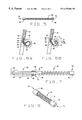
- FIG. 7 is a longitudinal cross-sectional view of a catheter and push wire combination adapted for delivery coils in accordance with the principles of the present invention.
- FIG. 8 is a perspective view of a fourth embodiment of a coil constructed according to the principles of this invention.
- FIG. 9A is a longitudinal cross-sectional view of a catheter adapted for delivering the coil of the fourth embodiment, prior to delivery of the coil;
- FIG. 9B is a longitudinal cross-sectional view of a catheter adapted for delivering the coil of the fourth embodiment, subsequent to delivery of the coil;
- FIG. 10 is a top plan view of a magnetic patch constructed according to the principles of this invention.
- FIG. 11 is a cross-sectional view of a the patch taken along the plane of line 8 — 8 in FIG. 7;
- FIG. 12A is a side elevation view of the patch deployed in an aneurysm
- FIG. 12B is a perspective view of an alternate apparatus for deploying the patch
- FIG. 13 is a cross-sectional view of the aneurysm, showing the patch occluding the opening of the aneurysm;
- FIG. 14 is a cross-sectional view of a magnetic pellet constructed according to the principles of this invention.
- FIG. 15 is a side elevation view of a catheter incorporating a coil in the distal end in accordance with the principles of this invention.
- FIG. 16 is a longitudinal cross-sectional view of the catheter shown in FIG. 15;
- FIG. 17 is a side elevation view of a catheter incorporation two coils in the distal end 26 in accordance with a first alternate embodiment.
- FIG. 18 is a transverse cross-sectional view of a catheter incorporating three coils in the distal end in accordance with a second alternative embodiment
- FIG. 19 is a side elevation view of the second alternative embodiment of a catheter
- FIG. 20 is a side elevation view of the second alternative embodiment of the catheter shown as it could be positioned in the neck of an aneurysm;
- FIG. 21A is a perspective view of a catheter constructed according to the principles of this invention.
- FIG. 21B is a perspective view of the split rectangular coil incorporated into the catheter of FIG. 21 A.
- a first embodiment of a magnetic coil constructed according to the principles of this invention is indicated generally as 20 in FIG. 1 .
- the magnetic coil 20 is preferably made from a permeable magnetic material, such as 400 series stainless steel of HipercoTM wire, or some other suitable material.
- the magnetic coil 20 could also be made from a permanent magnetic material, such as a combination of neodymium iron boron powder in a polymer binder.
- the magnetic coil 20 preferably has a length of between about 20 mm and about 200 mm, and a diameter of between about 0.010 inches and about 0.018 inches.
- the magnetic coil 20 is delivered to the site of the vascular defect in the patient, in this case an aneurysm, inside a catheter 22 .
- the catheter 22 may be a conventional catheter having a proximal end, a distal end 26 , and a lumen extending therebetween.
- the distal end 26 of the catheter 22 is navigated to the aneurysm, for example using a guide wire.
- the coil 20 is then ejected from the distal end 26 of the catheter 22 .
- a magnetic field, as indicated by arrows B, is applied at the site of the aneurysm to draw the coil 20 into the aneurysm. (The magnetic gradient is preferably parallel to the magnetic field).
- the coil 20 is advanced from the distal end 26 of the catheter 20 , and in contrast to when no magnetic field is applied as shown in FIG. 2A, the application of the magnetic field helps keep the coil within the aneurysm as shown in FIG. 2B, so that the coil 20 coils upon itself in the aneurysm. Additional coils 20 may be inserted in the aneurysm until the aneurysm is substantially filled, and blood flow in the aneurysm is reduced. This allows clotting in the aneurysm. Eventually the aneurysm is completely occluded.
- a second embodiment of a magnetic coil constructed according to the principles of this invention is indicated generally as 30 in FIG. 3 .
- the magnetic coil is preferably made from a nonmagnetic material, such as platinum, or some other suitable material.
- the magnetic coil 30 preferably has a length of between about 20 mm and about 200 mm, and a diameter of between about 0.010 inches and about 0.018 inches.
- the magnetic coil 30 has first and second ends 32 and 34 .
- a magnetic element 36 is secured at the first end 32 of the coil 30 .
- the magnetic element 36 can be a magnetically permeable material such as HipercoTM or cold rolled steel.
- the magnetic element 36 may also be a permanent magnetic material, such as Neodymium Iron Boron.
- the magnetic coil 30 is delivered to the site of the vascular defect in the patient, in this case an aneurysm, inside a catheter 22 .
- the first end 32 of the coil 30 is ejected from the distal end 26 of the catheter.
- a magnetic field, indicated by arrows B, is applied at the site of the aneurysm to draw the coil 30 into the aneurysm.
- the magnetic gradient is preferably parallel to the magnetic field.
- the coil 30 is advanced from the distal end 26 of the catheter 22 , and in contrast to when no magnetic field is applied as shown in FIG. 4A, the application of the magnetic field helps steer the end of the coil within the aneurysm as shown in FIG. 4B, so that the coil 30 coils upon itself in the aneurysm. Additional coils 30 may be inserted in the aneurysm until the aneurysm is substantially filled, and blood flow in the aneurysm is reduced.
- a third embodiment of a magnetic coil constructed according to the principles of this invention is indicated generally as 40 in FIG. 5 .
- the magnetic coil 40 is preferably made from a nonmagnetic material, such as platinum, or some other suitable material.
- the magnetic coil 40 preferably has a length of between about 20mm and about 200 mm, and a diameter of between about 0.010 inches and about 0.018 inches.
- the magnetic coil 40 has first and second ends 42 and 44 .
- a magnetic element 46 is secured to the first end 42
- a magnetic element 48 is secured to the second end 44 .
- the magnetic elements 46 and 48 can be a magnetic permeable material such as HipercoTM or cold rolled steel.
- the magnetic elements 46 and 48 may also be a magnetic material, such as Neodymium Iron Boron.
- the magnetic elements 46 and 48 allow the coils 40 to be joined end to end in the lumen 28 of the catheter 22 . This allows the coils to be delivered into the aneurysm in a continuous strand, if desired.
- a series of magnetic coils 40 is delivered to the site of the vascular defect in the patient, in this case an aneurysm, inside a catheter 22 .
- the first end 42 of the distal most coil 40 is ejected from the distal end 26 of the catheter 22 .
- a magnetic field indicated by arrows B is applied at the site of the aneurysm to draw the coil 40 into the aneurysm.
- the magnetic gradient is preferably parallel to the magnetic field).
- the coils 40 are advanced from the distal end 26 of the catheter 22 , and in contrast to when no magnetic field is applied as shown in FIG.
- the application of the magnetic field helps steer the ends 42 and 49 of the coil 40 within the aneurysm as shown in FIG. 6B, so that the coil 40 coils upon itself in the aneurysm.
- Additional coils 40 may be inserted in the aneurysm, either as a continuous strand, or separately until the aneurysm is substantially filled, and blood flow in the aneurysm is reduced.
- Adjacent coils 40 can be separated by changing the direction of the magnetic field or gradient to separate the adjacent coils.
- the distal end of a catheter 50 for delivering the coil 40 is shown in FIG. 7 .
- the catheter 50 could also be used to deliver coils 20 or 30 or any of the other magnetic objects of the present invention.
- the catheter 50 has a proximal end, a distal end 52 , and a central lumen 54 therein.
- a push wire 56 is disposed in the lumen 54 .
- the push wire 56 has a magnet 58 on its distal end.
- the push wire 56 also has a coil 60 on its distal end, generally surrounding the magnet 58 .
- Leads 62 and 64 extend proximally from the coil 60 , allowing the coil to be selectively connected to a power supply.
- the magnet 58 on the distal end of the push wire 56 magnetically engages the magnet 48 on the second end 44 of the coil 40 , allowing the push wire 56 to push the coil 40 out of the lumen 54 of the catheter 50 .
- the coil 60 can be energized, to neutralize the magnetic attraction between the magnet 58 and the magnet 48 on the second end 44 of the coil 40 , to thereby release the coil 40 .
- Coil 70 comprises a coil section 72 , and has a having a first end 74 and a second end 76 . There is a magnet 78 at the first end 74 , and a magnet 80 on the second end 76 .
- the magnets 78 and 80 are preferably tube-shaped.
- the distal end of a catheter 90 for delivering the coil 70 is shown in FIGS. 9A and 9B.
- the catheter 90 has a proximal end, a distal end 92 .
- the catheter 90 has a central lumen 94 with a circular cross-section, surrounded by an annular lumen 96 .
- the distal end of the annular lumen 96 is resiliently closed with a flap 98 .
- a push wire 100 having a magnet 102 on its distal end 104 can slide in the central lumen 94 . As show in FIG. 9A, the magnet 102 magnetically engages the magnet 80 on the second end 76 of the coil 70 .
- the push wire 100 can be advanced distally in the lumen which pushes the coil 70 distally out of the distal end of the lumen 96 . Once the coil 70 has been pushed out of the lumen 96 , the flaps 98 close behind it. As shown in FIG. 9B, when the push wire 90 is drawn proximally back into the central lumen 94 , the flaps 98 separate the coil 70 from the push wire 100 .
- a magnetic patch 120 constructed according to the principles of this invention is shown in FIGS. 10 and 11.
- the patch 120 is made from a highly flexible material such as silicone or polyurethane, or some other suitable material. In some embodiments it may be desirable to make the patch from a bioadsorbable material.
- the patch 120 includes a hoop 122 of nitinol “memory” wire, which allows the patch to be compressed to be delivered through the lumen of a catheter or by being wrapped around the distal end of the catheter.
- the hoop 122 causes the patch 120 to open to its normal (preferably round) shape.
- the patch 120 includes magnet material, for example particles of a magnetically responsive material or magnetic wire mesh.
- the magnetically responsive material may be a permeable magnetic material or it may be a permanent magnetic material. For example food grade iron particles of between about 0.05 ⁇ m and about 50 ⁇ m.
- the patch is delivered to the interior of the aneurysm. This is conveniently done by navigating the distal end 26 of the catheter 22 into the aneurysm. The patch 120 is then deployed from the lumen of the catheter 22 , and the hoop 122 causes the patch 120 to open to its full shape. Alternatively, as shown in FIG. 12B, the patch could be delivered wrapped on the outside of the distal end portion of the catheter 22 , and retained thereon by a retractable sheath 126 . The catheter 22 is navigated to the site of the vascular defect and the sheath 126 retracted distally to release the patch 120 at the site of the defect.
- a transverse magnetic gradient (gradient perpendicular to the field direction) is applied, with the patch 120 being magnetized along a long axis (along its surface) and the transverse gradient pulling the patch parallel to its thickness.
- the edge margins 124 of the patch 120 preferably have a wettable adhesive thereon, such as a hydrogel, cellulose ether, collagen, or even cyanoacrylate so that the edge margins of the patch adhere to the margins of the interior of the aneurysm surrounding the neck or opening of the aneurysm.
- the edge margins 124 of the patch 120 may have an adhesive activated by some other agent, such as a chemical agent, ultraviolet light, or laser.
- some other agent such as a chemical agent, ultraviolet light, or laser.
- the patch 120 covers the opening of the aneurysm.
- the patch can also have growth promoting substances on its surface, such as Vascular Endothelial Growth Factor (VEGF) promote growth of epithelial cells over the patch to close covered aneurysm opening.
- VEGF Vascular Endothelial Growth Factor
- the patch 120 could also be used to cover injured sections on the inside walls of the patient's vasculature.
- the patch might contain agents which promote healing and/or tissue growth, such as VEGR and even cells.
- the patch 120 could be applied to sites of plaque rupture, or to sites of intra-vascular therapy such as angioplasty or atherectomy.
- a patch 120 can be applied to one side of a blood vessel, while being held in place by a transverse gradient field, or multiple patches could be applied sequentially around the inside circumference of a blood vessel by successive rotating the field gradient direction. In this latter case, the patches would collectively form a continuous interior wall reinforcement, like a stent. This stent could be adsorbable over time by the body, and contain agents which promote healing of the arterial wall.
- the magnetic object can also be a pellet 130 comprising magnetically responsive particle 132 , with a coating 134 of a biocompatible material such as polyvinyl alcohol.
- the magnetically responsive particle 132 may be iron and preferably has a diameter of between about 1 ⁇ m and about 500 ⁇ m.
- the coating 134 the pellet preferably has a diameter of between about 100 ⁇ m and about 1000 ⁇ m.
- the pellets 130 can be delivered from the lumen of a catheter navigated to the site of the vascular defect.
- a magnetic field can be applied from an external source magnet to guide the pellets 130 into a particular branch of an atriovenous malformation, and hold them in place to occlude the malformation.
- a catheter 150 having a proximal end 152 , a distal end 154 , and a lumen 156 therebetween, is provided with a coil 158 formed in its distal end 154 .
- Leads 160 and 162 extend along the wall 164 of the catheter to selectively apply an electric current to the distal end 154 of the catheter 150 .
- the application of current to the coil 158 magnetizes the distal end 154 of the catheter 150 , allowing it be navigated by the application of a magnetic field with an external source magnet.
- the distal end 154 of the catheter 150 can be conveniently navigated to the site of the vascular defect by the application of a magnetic field, or with the assistance from an applied magnetic field.
- the magnetic objects in the lumen 156 are not sufficiently responsive to allow magnetic navigation of the catheter 150 containing them, magnetic objects or magnetic material in the lumen, together with the energized coil 158 , render the catheter sufficiently magnetically responsive so that it can be magnetically navigated or at least navigated with magnetic assistance.
- the coil 158 may be 5 mm (0.200 inch) long, and comprises 5 layers, each layer having 200 turns of AWG 50 insulated copper or silver magnet wire.
- the magnetic material in the lumen will typically have a ⁇ ranging from about 10 to about 100.
- a current of 0.2 A will achieve a magnetization of 1 T, which is comparable to permanent magnets used in magnetic navigation.
- With a current of 0.5 A a magnetic material in the lumen having a ⁇ of 10 will achieve a similar level of magnetization. Currents as high as 0.5 A in this coil should not significantly raise the local temperature, provided there is adequate blood flow for cooling.
- the coil 158 in catheter 150 also facilitates the delivery of magnetic materials, such as magnetic embolic agents.
- the coil 158 can be energized to help retain the magnetic embolic material in the catheter 150 as the catheter is navigated to and navigated from the site of the vascular defect, functioning as a valve.
- catheter 150 ′ An alternative construction of catheter 150 indicated as 150 ′ is shown in FIG. 17 .
- Catheter 150 ′ in addition to having coil 158 , also has coil 166 , with leads 168 and 170 extending along wall 164 .
- the coil 166 can be connected in series with coil 158 to enhance the magnetic effect at the distal tip of the catheter 150 ′.
- the coil 166 can also be connected oppositely from coil 158 , so that together the coils cut off the flow of magnetic embolic material through the lumen 156 of the catheter 150 ′, but the net magnetic effect distal to the catheter is negligible so that the catheter 150 ′ does not disturb the magnetic embolic agent that has already been deposited.
- a catheter 200 having a proximal end 202 , a distal end 204 , and a lumen 206 therebetween, is provided with three coils 208 , 210 , and 212 formed in its distal end 204 .
- the sidewall 214 of the catheter 200 contains leads 216 and 218 extending to coil 208 , leads 220 and 222 extending to coil 210 , and leads 224 and 226 extending to coil 212 .
- the leads allow the coils 208 , 210 and 212 to be selectively energized.
- the coils 208 , 210 , and 212 can be energized to facilitate magnetic navigation of the distal end 204 of the catheter 200 to the vascular defect.
- the coils can also be selectively energized at the site of the vascular defect to manipulate the distal end 204 of the catheter 200 to control the delivery of a magnetic embolic agent.
- a magnetic embolic agent For example, as shown in FIG. 20, if the catheter 200 has been navigated to an aneurysm and is being used to deliver a magnetic embolic agent into the dilatation or balloon of the catheter, the tip of the catheter would be pointing into the neck of the aneurysm, and the applied magnetic field would be preferably oriented transversely to the neck of the aneurysm, with the gradient oriented toward the back wall of the aneurysm, to deposit the magnetic embolic agent in layers in the aneurysm. Selectively energizing one or more of the coils 208 , 210 , and 212 allows the position of the distal end 204 of the catheter 200 to be adjusted.
- the catheters 150 and 150 ′ of the present invention also permit ejected magnetic material to be drawn into the lumen of the catheter.
- magnetic material can be magnetically drawn into the lumen even when the viscosity of the magnetic material and small lumen size would make it difficult or impossible to suction the material back into the lumen.
- the coils 158 and 166 can be differentially energized to apply a force to draw in magnetic material immediately adjacent the distal end of the catheter, and to repel magnetic material more than a few millimeters away. This prevents the catheter from drawing a string of material from the mass of ejected material or otherwise disturbing the mass of ejected material.
- FIG. 21 A A catheter 300 having a proximal end, a distal end 304 , and a lumen 306 therebetween is shown in FIG. 21 A.
- the wall 308 of the catheter 300 has a coil 310 embedded therein.
- the coil 310 is a split longitudinal coil.
- Leads 312 and 314 extend longitudinally in the wall 308 to the proximal end of the catheter 300 to permit the coil to be selectively connected to a power supply.
- Catheter 300 like catheter 200 can be manipulated within an applied magnetic field by selectively applying power to the coil 310 .
- An important aspect of this invention is the ability to visually monitor the treatment process.
- a preferred method is the use of bi-planar fluoroscopy to provide images of the treatment site in the patient.
- bi-planar imaging two images of the treatment site are provided from different angles (preferably 90° apart).
- Real time imaging has generally not been available in prior magnetic treatment procedures because the magnetic fields interfered with the operation of the imaging equipment.
- the inventors have discovered that by using shielded x-ray sources and digital imaging plates such as LAST plates, available from Varian Medical Systems, Inc., real time imaging can be provided in the presence of the relatively strong magnetic fields (which typically range from about 0.01 T to 0.5 T at the treatment site) for the magnetic treatment procedures of the present invention.
- Bi-planar imaging also provides a convenient interface for physician control of the procedure.
- the displays can be used by the physician to identify the current positions of the treatment devices and the desired future positions and orientations of the treatment devices.
- the user can manipulate a cursor or other indicator on the display with a mouse, joystick, or other input device and “click” at the points to identify a particular point.
- the point is uniquely identified in three dimensional space.
- the computer can then determine and implement the necessary movements of the external source magnet to achieve the desired future positions and orientations.
- the physician can also identify desired field and/or gradient directions on the displays, and the computer can then determine and implement the necessary movements of the external source magnet or electrical current changes in an electromagnet to achieve the desired field and/or gradient directions.
- a magnetic object for treating a vascular defect is delivered by navigating the distal end of a catheter to the site of the vascular defect.
- the magnetic object may or may not already be in the distal portion of the lumen of the catheter during this navigation.
- the coil is preferably at least partly ejected from the distal end 204 of the catheter and a magnetic field applied from an external source magnet.
- the field is preferably aligned in the direction of the opening of the aneurysm, and the gradient is preferably toward the back wall of the aneurysm.
- the applied magnetic field compresses the coil, pulling it toward the back wall of the aneurysm, and away from the open neck of the aneurysm. As more of the coil 20 is advanced into the aneurysm.
- the applied magnetic field prevents the end of the coil from snaking out the open neck, and allows the coil to be wound inside the aneurysm to substantially occlude the aneurysm. Additional coils 20 can be delivered in this manner until the aneurysm is satisfactorily occluded.
- the applied magnetic field steers the magnetic element 36 on the first end 22 of the coil toward the back wall of the aneurysm, and away from the open neck of the aneurysm.
- the applied magnetic field prevents the first end 32 of the coil 30 from snaking out the open neck, and allows the coil to be wound inside the aneurysm to substantially occlude the aneurysm. Additional coils 30 can be delivered in this manner until the aneurysm is satisfactorily occluded.
- the applied magnetic field steers the magnetic elements 46 and 48 on the ends 42 and 44 of the coil toward the back wall of the aneurysm, and away from the open neck of the aneurysm. This prevents the ends of the coil from snaking out the open neck, and allows the coil to be wound inside the aneurysm to substantially occlude the aneurysm.
- the coils 40 can be inserted continuously end to end, or each coil can be separately introduced.
- the coils can be separated at the distal end of the catheter 22 by turning the magnetic field to torque the magnetic element 48 on the proximal end 44 of the distal most coil 40 from the magnetic element 46 on the distal end 42 of the adjacent coil.
- a continuous strand of several coils 40 , or several separate coils 40 can be inserted until the aneurysm is satisfactorily occluded.
- a magnetic patch 50 the catheter 22 is navigated to the neck of the aneurysm, and the patch is introduced into the aneurysm.
- the resilient hoop 52 causes the patch to expand to its normal flat configuration.
- the blood present in the aneurysm wets the adhesive on the edge margins 54 of the patch 50 .
- a magnetic field is applied to the aneurysm to urge the patch 50 against the opening of the aneurysm. The magnetic field helps to hold the patch 50 in place until the patch is secured, occluding the opening of the aneurysm.
- the catheter 22 is navigated to the site of the vascular defect and the pellets are released from the distal end 26 of the catheter.
- a magnetic field is applied to the vascular defect, in a direction of the branch to be occluded.
- the pellets 60 align in the direction of the applied magnetic field and travel in the direction of the applied gradient to occlude the vascular defect.
- the catheter In the case of a magnetic embolic agent, the catheter is navigated to the site of the vascular defect. A magnetic field is applied and the magnetic embolic agent is ejected from the distal end of the catheter. The magnetic field rigidfies the ejected magnetic embolic agent. Thus, the magnetic field can be applied to rigidify the magnetic embolic agent and hold its shape until the magnetic embolic agent hardens on its own. A long rigid plug can be extruded from the catheter for occluding an atriovenous malformation. The applied magnetic field rigidifies and helps the plug retain its shape as the plug is advanced into the atriovenous malformation.
Abstract
Description
Claims (22)
Priority Applications (3)
| Application Number | Priority Date | Filing Date | Title |
|---|---|---|---|
| US09/430,118 US6375606B1 (en) | 1999-03-17 | 1999-10-29 | Methods of and apparatus for treating vascular defects |
| PCT/US2000/007101 WO2000054835A1 (en) | 1999-03-17 | 2000-03-16 | Methods of and apparatus for treating vascular defects |
| AU38941/00A AU3894100A (en) | 1999-03-17 | 2000-03-16 | Methods of and apparatus for treating vascular defects |
Applications Claiming Priority (2)
| Application Number | Priority Date | Filing Date | Title |
|---|---|---|---|
| US09/271,118 US6315709B1 (en) | 1998-08-07 | 1999-03-17 | Magnetic vascular defect treatment system |
| US09/430,118 US6375606B1 (en) | 1999-03-17 | 1999-10-29 | Methods of and apparatus for treating vascular defects |
Related Parent Applications (1)
| Application Number | Title | Priority Date | Filing Date |
|---|---|---|---|
| US09/271,118 Continuation-In-Part US6315709B1 (en) | 1998-08-07 | 1999-03-17 | Magnetic vascular defect treatment system |
Publications (1)
| Publication Number | Publication Date |
|---|---|
| US6375606B1 true US6375606B1 (en) | 2002-04-23 |
Family
ID=26954698
Family Applications (1)
| Application Number | Title | Priority Date | Filing Date |
|---|---|---|---|
| US09/430,118 Expired - Fee Related US6375606B1 (en) | 1999-03-17 | 1999-10-29 | Methods of and apparatus for treating vascular defects |
Country Status (3)
| Country | Link |
|---|---|
| US (1) | US6375606B1 (en) |
| AU (1) | AU3894100A (en) |
| WO (1) | WO2000054835A1 (en) |
Cited By (240)
| Publication number | Priority date | Publication date | Assignee | Title |
|---|---|---|---|---|
| US20020177789A1 (en) * | 2001-05-06 | 2002-11-28 | Ferry Steven J. | System and methods for advancing a catheter |
| US6524303B1 (en) * | 2000-09-08 | 2003-02-25 | Stereotaxis, Inc. | Variable stiffness magnetic catheter |
| US6540657B2 (en) * | 2000-12-28 | 2003-04-01 | Scimed Life Systems, Inc. | Apparatus and method for internally inducing a magnetic field in an aneurysm to embolize aneurysm with magnetically-controllable substance |
| US6544163B2 (en) * | 2000-12-28 | 2003-04-08 | Scimed Life Systems, Inc. | Apparatus and method for controlling a magnetically controllable embolic in the embolization of an aneurysm |
| US6603994B2 (en) * | 2000-12-28 | 2003-08-05 | Scimed Life Systems, Inc. | Apparatus and method for internally inducing a magnetic field in an aneurysm to embolize aneurysm with magnetically-controllable substance |
| US6626819B2 (en) * | 2001-01-12 | 2003-09-30 | Scimed Life Systems, Inc. | Permanent magnetic and electromagnetic apparatus for embolizing an aneurysm with magnetically controllable embolic and method |
| US20040019447A1 (en) * | 2002-07-16 | 2004-01-29 | Yehoshua Shachar | Apparatus and method for catheter guidance control and imaging |
| US20040096511A1 (en) * | 2002-07-03 | 2004-05-20 | Jonathan Harburn | Magnetically guidable carriers and methods for the targeted magnetic delivery of substances in the body |
| US20040157082A1 (en) * | 2002-07-22 | 2004-08-12 | Ritter Rogers C. | Coated magnetically responsive particles, and embolic materials using coated magnetically responsive particles |
| US20040169316A1 (en) * | 2002-03-28 | 2004-09-02 | Siliconix Taiwan Ltd. | Encapsulation method and leadframe for leadless semiconductor packages |
| US20050096589A1 (en) * | 2003-10-20 | 2005-05-05 | Yehoshua Shachar | System and method for radar-assisted catheter guidance and control |
| US20050113812A1 (en) * | 2003-09-16 | 2005-05-26 | Viswanathan Raju R. | User interface for remote control of medical devices |
| US20060036163A1 (en) * | 2004-07-19 | 2006-02-16 | Viswanathan Raju R | Method of, and apparatus for, controlling medical navigation systems |
| US20060041182A1 (en) * | 2003-04-16 | 2006-02-23 | Forbes Zachary G | Magnetically-controllable delivery system for therapeutic agents |
| US20060079745A1 (en) * | 2004-10-07 | 2006-04-13 | Viswanathan Raju R | Surgical navigation with overlay on anatomical images |
| US20060144407A1 (en) * | 2004-07-20 | 2006-07-06 | Anthony Aliberto | Magnetic navigation manipulation apparatus |
| US20060144408A1 (en) * | 2004-07-23 | 2006-07-06 | Ferry Steven J | Micro-catheter device and method of using same |
| WO2006042117A3 (en) * | 2004-10-06 | 2006-10-26 | Sherwood Serv Ag | Systems and methods for thermally profiling radiofrequency electrodes |
| WO2006116979A1 (en) * | 2005-05-03 | 2006-11-09 | Medizinische Fakultät | Catheter |
| US20060270915A1 (en) * | 2005-01-11 | 2006-11-30 | Ritter Rogers C | Navigation using sensed physiological data as feedback |
| US20060276867A1 (en) * | 2005-06-02 | 2006-12-07 | Viswanathan Raju R | Methods and devices for mapping the ventricle for pacing lead placement and therapy delivery |
| US20060278246A1 (en) * | 2003-05-21 | 2006-12-14 | Michael Eng | Electrophysiology catheter |
| US20060281990A1 (en) * | 2005-05-06 | 2006-12-14 | Viswanathan Raju R | User interfaces and navigation methods for vascular navigation |
| US20060281989A1 (en) * | 2005-05-06 | 2006-12-14 | Viswanathan Raju R | Voice controlled user interface for remote navigation systems |
| US20070016131A1 (en) * | 2005-07-12 | 2007-01-18 | Munger Gareth T | Flexible magnets for navigable medical devices |
| US20070016006A1 (en) * | 2005-05-27 | 2007-01-18 | Yehoshua Shachar | Apparatus and method for shaped magnetic field control for catheter, guidance, control, and imaging |
| US20070021744A1 (en) * | 2005-07-07 | 2007-01-25 | Creighton Francis M Iv | Apparatus and method for performing ablation with imaging feedback |
| US20070021742A1 (en) * | 2005-07-18 | 2007-01-25 | Viswanathan Raju R | Estimation of contact force by a medical device |
| US20070019330A1 (en) * | 2005-07-12 | 2007-01-25 | Charles Wolfersberger | Apparatus for pivotally orienting a projection device |
| US20070021731A1 (en) * | 1997-11-12 | 2007-01-25 | Garibaldi Jeffrey M | Method of and apparatus for navigating medical devices in body lumens |
| US20070030958A1 (en) * | 2005-07-15 | 2007-02-08 | Munger Gareth T | Magnetically shielded x-ray tube |
| US20070038064A1 (en) * | 2005-07-08 | 2007-02-15 | Creighton Francis M Iv | Magnetic navigation and imaging system |
| US20070038074A1 (en) * | 1998-02-09 | 2007-02-15 | Ritter Rogers C | Method and device for locating magnetic implant source field |
| US20070038410A1 (en) * | 2005-08-10 | 2007-02-15 | Ilker Tunay | Method and apparatus for dynamic magnetic field control using multiple magnets |
| US20070038065A1 (en) * | 2005-07-07 | 2007-02-15 | Creighton Francis M Iv | Operation of a remote medical navigation system using ultrasound image |
| US20070043455A1 (en) * | 2005-07-26 | 2007-02-22 | Viswanathan Raju R | Apparatus and methods for automated sequential movement control for operation of a remote navigation system |
| US20070040670A1 (en) * | 2005-07-26 | 2007-02-22 | Viswanathan Raju R | System and network for remote medical procedures |
| US20070055124A1 (en) * | 2005-09-01 | 2007-03-08 | Viswanathan Raju R | Method and system for optimizing left-heart lead placement |
| US20070060829A1 (en) * | 2005-07-21 | 2007-03-15 | Carlo Pappone | Method of finding the source of and treating cardiac arrhythmias |
| US20070060966A1 (en) * | 2005-07-11 | 2007-03-15 | Carlo Pappone | Method of treating cardiac arrhythmias |
| US20070060962A1 (en) * | 2005-07-26 | 2007-03-15 | Carlo Pappone | Apparatus and methods for cardiac resynchronization therapy and cardiac contractility modulation |
| US20070062546A1 (en) * | 2005-06-02 | 2007-03-22 | Viswanathan Raju R | Electrophysiology catheter and system for gentle and firm wall contact |
| US20070062547A1 (en) * | 2005-07-21 | 2007-03-22 | Carlo Pappone | Systems for and methods of tissue ablation |
| US20070088077A1 (en) * | 1991-02-26 | 2007-04-19 | Plasse Terry F | Appetite stimulation and reduction of weight loss in patients suffering from symptomatic hiv infection |
| US20070088197A1 (en) * | 2000-02-16 | 2007-04-19 | Sterotaxis, Inc. | Magnetic medical devices with changeable magnetic moments and method of navigating magnetic medical devices with changeable magnetic moments |
| US20070149946A1 (en) * | 2005-12-07 | 2007-06-28 | Viswanathan Raju R | Advancer system for coaxial medical devices |
| US20070161882A1 (en) * | 2006-01-06 | 2007-07-12 | Carlo Pappone | Electrophysiology catheter and system for gentle and firm wall contact |
| US20070168021A1 (en) * | 2006-01-17 | 2007-07-19 | Holmes David R Jr | Porous three dimensional nest scaffolding |
| US20070167720A1 (en) * | 2005-12-06 | 2007-07-19 | Viswanathan Raju R | Smart card control of medical devices |
| US20070197906A1 (en) * | 2006-01-24 | 2007-08-23 | Ritter Rogers C | Magnetic field shape-adjustable medical device and method of using the same |
| US20070197899A1 (en) * | 2006-01-17 | 2007-08-23 | Ritter Rogers C | Apparatus and method for magnetic navigation using boost magnets |
| US20070197891A1 (en) * | 2006-02-23 | 2007-08-23 | Yehoshua Shachar | Apparatus for magnetically deployable catheter with MOSFET sensor and method for mapping and ablation |
| US20070250041A1 (en) * | 2006-04-19 | 2007-10-25 | Werp Peter R | Extendable Interventional Medical Devices |
| US20070287909A1 (en) * | 1998-08-07 | 2007-12-13 | Stereotaxis, Inc. | Method and apparatus for magnetically controlling catheters in body lumens and cavities |
| US20080006280A1 (en) * | 2004-07-20 | 2008-01-10 | Anthony Aliberto | Magnetic navigation maneuvering sheath |
| US20080015664A1 (en) * | 2004-10-06 | 2008-01-17 | Podhajsky Ronald J | Systems and methods for thermally profiling radiofrequency electrodes |
| US20080015427A1 (en) * | 2006-06-30 | 2008-01-17 | Nathan Kastelein | System and network for remote medical procedures |
| US20080015670A1 (en) * | 2006-01-17 | 2008-01-17 | Carlo Pappone | Methods and devices for cardiac ablation |
| US20080016677A1 (en) * | 2002-01-23 | 2008-01-24 | Stereotaxis, Inc. | Rotating and pivoting magnet for magnetic navigation |
| US20080027482A1 (en) * | 2006-07-28 | 2008-01-31 | Terumo Kabushiki Kaisha | Elongate medical device |
| US20080039830A1 (en) * | 2006-08-14 | 2008-02-14 | Munger Gareth T | Method and Apparatus for Ablative Recanalization of Blocked Vasculature |
| US20080045892A1 (en) * | 2001-05-06 | 2008-02-21 | Ferry Steven J | System and Methods for Advancing a Catheter |
| US20080047568A1 (en) * | 1999-10-04 | 2008-02-28 | Ritter Rogers C | Method for Safely and Efficiently Navigating Magnetic Devices in the Body |
| US20080059598A1 (en) * | 2006-09-06 | 2008-03-06 | Garibaldi Jeffrey M | Coordinated Control for Multiple Computer-Controlled Medical Systems |
| US20080055239A1 (en) * | 2006-09-06 | 2008-03-06 | Garibaldi Jeffrey M | Global Input Device for Multiple Computer-Controlled Medical Systems |
| US20080058609A1 (en) * | 2006-09-06 | 2008-03-06 | Stereotaxis, Inc. | Workflow driven method of performing multi-step medical procedures |
| US20080064969A1 (en) * | 2006-09-11 | 2008-03-13 | Nathan Kastelein | Automated Mapping of Anatomical Features of Heart Chambers |
| US20080065061A1 (en) * | 2006-09-08 | 2008-03-13 | Viswanathan Raju R | Impedance-Based Cardiac Therapy Planning Method with a Remote Surgical Navigation System |
| US20080077007A1 (en) * | 2002-06-28 | 2008-03-27 | Hastings Roger N | Method of Navigating Medical Devices in the Presence of Radiopaque Material |
| US20080097200A1 (en) * | 2006-10-20 | 2008-04-24 | Blume Walter M | Location and Display of Occluded Portions of Vessels on 3-D Angiographic Images |
| US20080123716A1 (en) * | 2006-09-13 | 2008-05-29 | Sherwood Services Ag | Portable thermally profiling phantom and method of using the same |
| US20080132910A1 (en) * | 2006-11-07 | 2008-06-05 | Carlo Pappone | Control for a Remote Navigation System |
| US20080200913A1 (en) * | 2007-02-07 | 2008-08-21 | Viswanathan Raju R | Single Catheter Navigation for Diagnosis and Treatment of Arrhythmias |
| US20080228068A1 (en) * | 2007-03-13 | 2008-09-18 | Viswanathan Raju R | Automated Surgical Navigation with Electro-Anatomical and Pre-Operative Image Data |
| US20080228065A1 (en) * | 2007-03-13 | 2008-09-18 | Viswanathan Raju R | System and Method for Registration of Localization and Imaging Systems for Navigational Control of Medical Devices |
| US20080249395A1 (en) * | 2007-04-06 | 2008-10-09 | Yehoshua Shachar | Method and apparatus for controlling catheter positioning and orientation |
| US20080287909A1 (en) * | 2007-05-17 | 2008-11-20 | Viswanathan Raju R | Method and apparatus for intra-chamber needle injection treatment |
| US20080292901A1 (en) * | 2007-05-24 | 2008-11-27 | Hon Hai Precision Industry Co., Ltd. | Magnesium alloy and thin workpiece made of the same |
| US20080294232A1 (en) * | 2007-05-22 | 2008-11-27 | Viswanathan Raju R | Magnetic cell delivery |
| US20090005766A1 (en) * | 2007-06-28 | 2009-01-01 | Joseph Brannan | Broadband microwave applicator |
| US20090012821A1 (en) * | 2007-07-06 | 2009-01-08 | Guy Besson | Management of live remote medical display |
| US20090062646A1 (en) * | 2005-07-07 | 2009-03-05 | Creighton Iv Francis M | Operation of a remote medical navigation system using ultrasound image |
| US20090062772A1 (en) * | 2007-08-30 | 2009-03-05 | Syncro Medical Innovations, Inc. | Guided catheter with removable magnetic guide |
| US20090105579A1 (en) * | 2007-10-19 | 2009-04-23 | Garibaldi Jeffrey M | Method and apparatus for remotely controlled navigation using diagnostically enhanced intra-operative three-dimensional image data |
| US20090118613A1 (en) * | 2007-11-01 | 2009-05-07 | Tyco Healthcare Group Lp | Method for Volume Determination and Geometric Reconstruction |
| US20090131927A1 (en) * | 2007-11-20 | 2009-05-21 | Nathan Kastelein | Method and apparatus for remote detection of rf ablation |
| US20090131798A1 (en) * | 2007-11-19 | 2009-05-21 | Minar Christopher D | Method and apparatus for intravascular imaging and occlusion crossing |
| US20090131926A1 (en) * | 2007-11-16 | 2009-05-21 | Tyco Healthcare Group Lp | Dynamically Matched Microwave Antenna for Tissue Ablation |
| US20090138004A1 (en) * | 2007-11-27 | 2009-05-28 | Vivant Medical, Inc. | System and Method for Field Ablation Prediction |
| US7543239B2 (en) | 2004-06-04 | 2009-06-02 | Stereotaxis, Inc. | User interface for remote control of medical devices |
| US20090177032A1 (en) * | 1999-04-14 | 2009-07-09 | Garibaldi Jeffrey M | Method and apparatus for magnetically controlling endoscopes in body lumens and cavities |
| US20090177037A1 (en) * | 2007-06-27 | 2009-07-09 | Viswanathan Raju R | Remote control of medical devices using real time location data |
| US20090187180A1 (en) * | 2008-01-23 | 2009-07-23 | Vivant Medical, Inc. | Choked Dielectric Loaded Tip Dipole Microwave Antenna |
| US20090192510A1 (en) * | 2008-01-29 | 2009-07-30 | Tyco Healthcare Group Lp | Polyp Encapsulation System and Method |
| US20090192412A1 (en) * | 2008-01-23 | 2009-07-30 | Mediguide Ltd. | Sensor mounted flexible guidewire |
| US20090198226A1 (en) * | 2008-01-31 | 2009-08-06 | Vivant Medical, Inc. | Medical Device Including Member that Deploys in a Spiral-Like Configuration and Method |
| US20090198227A1 (en) * | 2008-01-31 | 2009-08-06 | Vivant Medical, Inc. | Articulating Ablation Device and Method |
| US20090248005A1 (en) * | 2008-03-27 | 2009-10-01 | Rusin Christopher T | Microwave Ablation Devices Including Expandable Antennas and Methods of Use |
| US20090248006A1 (en) * | 2008-03-31 | 2009-10-01 | Paulus Joseph A | Re-Hydration Antenna for Ablation |
| US20090275828A1 (en) * | 2008-05-01 | 2009-11-05 | Magnetecs, Inc. | Method and apparatus for creating a high resolution map of the electrical and mechanical properties of the heart |
| US20090306652A1 (en) * | 2008-06-09 | 2009-12-10 | Buysse Steven P | Ablation Needle Guide |
| US20090306659A1 (en) * | 2008-06-09 | 2009-12-10 | Buysse Steven P | Surface Ablation Process With Electrode Cooling Methods |
| US20100030208A1 (en) * | 2008-07-29 | 2010-02-04 | Tyco Healthcare Group Lp | Method for Ablation Volume Determination and Geometric Reconstruction |
| US20100045558A1 (en) * | 2008-08-25 | 2010-02-25 | Vivant Medical, Inc. | Dual-Band Dipole Microwave Ablation Antenna |
| US20100045559A1 (en) * | 2008-08-25 | 2010-02-25 | Vivant Medical, Inc. | Dual-Band Dipole Microwave Ablation Antenna |
| US20100053015A1 (en) * | 2008-08-28 | 2010-03-04 | Vivant Medical, Inc. | Microwave Antenna |
| US20100057070A1 (en) * | 2008-09-03 | 2010-03-04 | Vivant Medical, Inc. | Microwave Shielding Apparatus |
| US20100087808A1 (en) * | 2008-10-03 | 2010-04-08 | Vivant Medical, Inc. | Combined Frequency Microwave Ablation System, Devices and Methods of Use |
| US20100097284A1 (en) * | 2008-10-17 | 2010-04-22 | Vivant Medical, Inc. | Choked Dielectric Loaded Tip Dipole Microwave Antenna |
| US20100130854A1 (en) * | 2008-11-25 | 2010-05-27 | Magnetecs, Inc. | System and method for a catheter impedance seeking device |
| US20100145147A1 (en) * | 2008-09-02 | 2010-06-10 | Syncro Medical Innovations, Inc. | Magnetic device for guiding catheter and method of use therefor |
| US20100163061A1 (en) * | 2000-04-11 | 2010-07-01 | Creighton Francis M | Magnets with varying magnetization direction and method of making such magnets |
| US7751867B2 (en) | 2004-12-20 | 2010-07-06 | Stereotaxis, Inc. | Contact over-torque with three-dimensional anatomical data |
| US7756308B2 (en) | 2005-02-07 | 2010-07-13 | Stereotaxis, Inc. | Registration of three dimensional image data to 2D-image-derived data |
| US20100217251A1 (en) * | 2009-02-20 | 2010-08-26 | Vivant Medical, Inc. | Leaky-Wave Antennas for Medical Applications |
| US20100222669A1 (en) * | 2006-08-23 | 2010-09-02 | William Flickinger | Medical device guide |
| US20100256624A1 (en) * | 2009-04-01 | 2010-10-07 | Vivant Medical, Inc. | Microwave Ablation System with User-Controlled Ablation Size and Method of Use |
| US20100262134A1 (en) * | 2009-04-14 | 2010-10-14 | Vivant Medical, Inc. | Frequency Identification for Microwave Ablation Probes |
| US7818076B2 (en) | 2005-07-26 | 2010-10-19 | Stereotaxis, Inc. | Method and apparatus for multi-system remote surgical navigation from a single control center |
| US20100286683A1 (en) * | 2009-05-06 | 2010-11-11 | Vivant Medical, Inc. | Power-Stage Antenna Integrated System with High-Strength Shaft |
| US20100286682A1 (en) * | 2009-05-06 | 2010-11-11 | Vivant Medical, Inc. | Power-Stage Antenna Integrated System with Junction Member |
| US20100286681A1 (en) * | 2009-05-06 | 2010-11-11 | Vivant Medical, Inc. | Power-Stage Antenna Integrated System |
| US20100305502A1 (en) * | 2001-05-06 | 2010-12-02 | Ferry Steven J | Systems and methods for medical device advancement and rotation |
| US20100305560A1 (en) * | 2009-05-29 | 2010-12-02 | Vivant Medical, Inc. | Microwave Ablation Safety Pad, Microwave Safety Pad System and Method of Use |
| US20100331834A1 (en) * | 2009-06-29 | 2010-12-30 | Vivant Medical,Inc. | Ablation Probe Fixation |
| US20110034913A1 (en) * | 2009-08-05 | 2011-02-10 | Vivant Medical, Inc. | Directive Window Ablation Antenna with Dielectric Loading |
| US20110034919A1 (en) * | 2009-08-06 | 2011-02-10 | Vivant Medical, Inc. | Vented Positioner and Spacer and Method of Use |
| US20110040177A1 (en) * | 2007-08-27 | 2011-02-17 | William Harrison Zum | Automated vessel repair system, devices and methods |
| US20110040300A1 (en) * | 2009-08-17 | 2011-02-17 | Vivant Medical, Inc. | Surface Ablation Antenna with Dielectric Loading |
| US20110046618A1 (en) * | 2009-08-04 | 2011-02-24 | Minar Christopher D | Methods and systems for treating occluded blood vessels and other body cannula |
| USD634010S1 (en) | 2009-08-05 | 2011-03-08 | Vivant Medical, Inc. | Medical device indicator guide |
| US20110060325A1 (en) * | 2009-09-08 | 2011-03-10 | Vivant Medical, Inc. | Microwave Antenna Probe with High-Strength Ceramic Coupler |
| US20110066144A1 (en) * | 2009-09-16 | 2011-03-17 | Vivant Medical, Inc. | Perfused Core Dielectrically Loaded Dipole Microwave Antenna Probe |
| US20110092808A1 (en) * | 2009-10-20 | 2011-04-21 | Magnetecs, Inc. | Method for acquiring high density mapping data with a catheter guidance system |
| US20110091853A1 (en) * | 2009-10-20 | 2011-04-21 | Magnetecs, Inc. | Method for simulating a catheter guidance system for control, development and training applications |
| US20110112396A1 (en) * | 2009-11-09 | 2011-05-12 | Magnetecs, Inc. | System and method for targeting catheter electrodes |
| US20110130718A1 (en) * | 2009-05-25 | 2011-06-02 | Kidd Brian L | Remote Manipulator Device |
| US7961924B2 (en) | 2006-08-21 | 2011-06-14 | Stereotaxis, Inc. | Method of three-dimensional device localization using single-plane imaging |
| US7966059B2 (en) | 1999-10-04 | 2011-06-21 | Stereotaxis, Inc. | Rotating and pivoting magnet for magnetic navigation |
| US20110152721A1 (en) * | 2008-01-23 | 2011-06-23 | Ran Sela | Sensor mounted flexible guidewire |
| EP2365007A2 (en) | 2003-04-16 | 2011-09-14 | The Children's Hospital of Philadelphia | Magnetically controllable drug and gene delivery stents |
| US8196590B2 (en) | 2003-05-02 | 2012-06-12 | Stereotaxis, Inc. | Variable magnetic moment MR navigation |
| US8202270B2 (en) | 2009-02-20 | 2012-06-19 | Vivant Medical, Inc. | Leaky-wave antennas for medical applications |
| US8231618B2 (en) | 2007-11-05 | 2012-07-31 | Stereotaxis, Inc. | Magnetically guided energy delivery apparatus |
| US8242972B2 (en) | 2006-09-06 | 2012-08-14 | Stereotaxis, Inc. | System state driven display for medical procedures |
| US8246614B2 (en) | 2008-04-17 | 2012-08-21 | Vivant Medical, Inc. | High-strength microwave antenna coupling |
| US8292881B2 (en) | 2009-05-27 | 2012-10-23 | Vivant Medical, Inc. | Narrow gauge high strength choked wet tip microwave ablation antenna |
| US8292880B2 (en) | 2007-11-27 | 2012-10-23 | Vivant Medical, Inc. | Targeted cooling of deployable microwave antenna |
| US8308628B2 (en) | 2009-11-02 | 2012-11-13 | Pulse Therapeutics, Inc. | Magnetic-based systems for treating occluded vessels |
| US8328860B2 (en) | 2007-03-13 | 2012-12-11 | Covidien Lp | Implant including a coil and a stretch-resistant member |
| USD673685S1 (en) | 2010-09-08 | 2013-01-01 | Vivant Medical, Inc. | Microwave device spacer and positioner with arcuate slot |
| US8369930B2 (en) | 2009-06-16 | 2013-02-05 | MRI Interventions, Inc. | MRI-guided devices and MRI-guided interventional systems that can track and generate dynamic visualizations of the devices in near real time |
| US8419681B2 (en) | 2002-11-18 | 2013-04-16 | Stereotaxis, Inc. | Magnetically navigable balloon catheters |
| US8437833B2 (en) | 2008-10-07 | 2013-05-07 | Bard Access Systems, Inc. | Percutaneous magnetic gastrostomy |
| US20130138117A1 (en) * | 2010-02-17 | 2013-05-30 | The University Of Utah Research Foundation | Cochlear implant insertion method and system |
| US8478382B2 (en) | 2008-02-11 | 2013-07-02 | C. R. Bard, Inc. | Systems and methods for positioning a catheter |
| US8512256B2 (en) | 2006-10-23 | 2013-08-20 | Bard Access Systems, Inc. | Method of locating the tip of a central venous catheter |
| US8552915B2 (en) | 2009-06-19 | 2013-10-08 | Covidien Lp | Microwave ablation antenna radiation detector |
| US8774907B2 (en) | 2006-10-23 | 2014-07-08 | Bard Access Systems, Inc. | Method of locating the tip of a central venous catheter |
| US8781555B2 (en) | 2007-11-26 | 2014-07-15 | C. R. Bard, Inc. | System for placement of a catheter including a signal-generating stylet |
| US8777979B2 (en) | 2006-04-17 | 2014-07-15 | Covidien Lp | System and method for mechanically positioning intravascular implants |
| US8777978B2 (en) | 2006-04-17 | 2014-07-15 | Covidien Lp | System and method for mechanically positioning intravascular implants |
| US8784336B2 (en) | 2005-08-24 | 2014-07-22 | C. R. Bard, Inc. | Stylet apparatuses and methods of manufacture |
| US8801693B2 (en) | 2010-10-29 | 2014-08-12 | C. R. Bard, Inc. | Bioimpedance-assisted placement of a medical device |
| US8801747B2 (en) | 2007-03-13 | 2014-08-12 | Covidien Lp | Implant, a mandrel, and a method of forming an implant |
| US8849382B2 (en) | 2007-11-26 | 2014-09-30 | C. R. Bard, Inc. | Apparatus and display methods relating to intravascular placement of a catheter |
| US8894641B2 (en) | 2009-10-27 | 2014-11-25 | Covidien Lp | System and method for monitoring ablation size |
| US8945144B2 (en) | 2010-09-08 | 2015-02-03 | Covidien Lp | Microwave spacers and method of use |
| US8968289B2 (en) | 2010-10-22 | 2015-03-03 | Covidien Lp | Microwave spacers and methods of use |
| USD724745S1 (en) | 2011-08-09 | 2015-03-17 | C. R. Bard, Inc. | Cap for an ultrasound probe |
| US9011480B2 (en) | 2012-01-20 | 2015-04-21 | Covidien Lp | Aneurysm treatment coils |
| US9050095B2 (en) | 2004-09-22 | 2015-06-09 | Covidien Lp | Medical implant |
| US9057468B2 (en) | 2007-11-27 | 2015-06-16 | Covidien Lp | Wedge coupling |
| WO2015095378A1 (en) * | 2013-12-17 | 2015-06-25 | Board Of Regents Of The University Of Nebraska | Platform device and method of use to assist in anastomosis formation |
| CN104784824A (en) * | 2015-05-08 | 2015-07-22 | 河南瑞安医疗器械有限公司 | Head locator |
| US9113624B2 (en) | 2008-10-15 | 2015-08-25 | Covidien Lp | System and method for perfusing biological organs |
| US9125578B2 (en) | 2009-06-12 | 2015-09-08 | Bard Access Systems, Inc. | Apparatus and method for catheter navigation and tip location |
| US9198665B2 (en) | 2004-09-22 | 2015-12-01 | Covidien Lp | Micro-spiral implantation device |
| US9211107B2 (en) | 2011-11-07 | 2015-12-15 | C. R. Bard, Inc. | Ruggedized ultrasound hydrogel insert |
| US9254172B2 (en) | 2008-09-03 | 2016-02-09 | Covidien Lp | Shielding for an isolation apparatus used in a microwave generator |
| US9259290B2 (en) | 2009-06-08 | 2016-02-16 | MRI Interventions, Inc. | MRI-guided surgical systems with proximity alerts |
| USD754357S1 (en) | 2011-08-09 | 2016-04-19 | C. R. Bard, Inc. | Ultrasound probe head |
| US9339206B2 (en) | 2009-06-12 | 2016-05-17 | Bard Access Systems, Inc. | Adaptor for endovascular electrocardiography |
| US9445734B2 (en) | 2009-06-12 | 2016-09-20 | Bard Access Systems, Inc. | Devices and methods for endovascular electrography |
| US9456766B2 (en) | 2007-11-26 | 2016-10-04 | C. R. Bard, Inc. | Apparatus for use with needle insertion guidance system |
| US9492097B2 (en) | 2007-11-26 | 2016-11-15 | C. R. Bard, Inc. | Needle length determination and calibration for insertion guidance system |
| US9521961B2 (en) | 2007-11-26 | 2016-12-20 | C. R. Bard, Inc. | Systems and methods for guiding a medical instrument |
| US9532724B2 (en) | 2009-06-12 | 2017-01-03 | Bard Access Systems, Inc. | Apparatus and method for catheter navigation using endovascular energy mapping |
| US9554716B2 (en) | 2007-11-26 | 2017-01-31 | C. R. Bard, Inc. | Insertion guidance system for needles and medical components |
| US9579104B2 (en) | 2011-11-30 | 2017-02-28 | Covidien Lp | Positioning and detaching implants |
| US9636031B2 (en) | 2007-11-26 | 2017-05-02 | C.R. Bard, Inc. | Stylets for use with apparatus for intravascular placement of a catheter |
| US9649048B2 (en) | 2007-11-26 | 2017-05-16 | C. R. Bard, Inc. | Systems and methods for breaching a sterile field for intravascular placement of a catheter |
| US9681916B2 (en) | 2012-01-06 | 2017-06-20 | Covidien Lp | System and method for treating tissue using an expandable antenna |
| US9681823B2 (en) | 2007-11-26 | 2017-06-20 | C. R. Bard, Inc. | Integrated system for intravascular placement of a catheter |
| US9687245B2 (en) | 2012-03-23 | 2017-06-27 | Covidien Lp | Occlusive devices and methods of use |
| US20170181653A1 (en) * | 2015-12-23 | 2017-06-29 | Biosense Webster (Israel) Ltd. | Multi-layered catheter shaft construction with embedded single axial sensors, and related methods |
| US9693823B2 (en) | 2012-01-06 | 2017-07-04 | Covidien Lp | System and method for treating tissue using an expandable antenna |
| US9713475B2 (en) | 2014-04-18 | 2017-07-25 | Covidien Lp | Embolic medical devices |
| US9839372B2 (en) | 2014-02-06 | 2017-12-12 | C. R. Bard, Inc. | Systems and methods for guidance and placement of an intravascular device |
| US9883878B2 (en) | 2012-05-15 | 2018-02-06 | Pulse Therapeutics, Inc. | Magnetic-based systems and methods for manipulation of magnetic particles |
| US9901714B2 (en) | 2008-08-22 | 2018-02-27 | C. R. Bard, Inc. | Catheter assembly including ECG sensor and magnetic assemblies |
| US10046139B2 (en) | 2010-08-20 | 2018-08-14 | C. R. Bard, Inc. | Reconfirmation of ECG-assisted catheter tip placement |
| US10349890B2 (en) | 2015-06-26 | 2019-07-16 | C. R. Bard, Inc. | Connector interface for ECG-based catheter positioning system |
| US10449330B2 (en) | 2007-11-26 | 2019-10-22 | C. R. Bard, Inc. | Magnetic element-equipped needle assemblies |
| US10524691B2 (en) | 2007-11-26 | 2020-01-07 | C. R. Bard, Inc. | Needle assembly including an aligned magnetic element |
| US10575839B2 (en) | 2014-07-29 | 2020-03-03 | University Of Kansas | Solenoid occlusion device |
| US10639008B2 (en) | 2009-10-08 | 2020-05-05 | C. R. Bard, Inc. | Support and cover structures for an ultrasound probe head |
| EP3692931A1 (en) * | 2019-02-06 | 2020-08-12 | DePuy Synthes Products, Inc. | Adhesive cover occluding device for aneurysm treatment |
| US10751509B2 (en) | 2007-11-26 | 2020-08-25 | C. R. Bard, Inc. | Iconic representations for guidance of an indwelling medical device |
| US20200330730A1 (en) * | 2019-04-18 | 2020-10-22 | UNandUP, LLC. | Magnetically controlled medical devices for interventional medical procedures and methods of making and controlling the same |
| US10820885B2 (en) | 2012-06-15 | 2020-11-03 | C. R. Bard, Inc. | Apparatus and methods for detection of a removable cap on an ultrasound probe |
| US10905430B2 (en) | 2018-01-24 | 2021-02-02 | DePuy Synthes Products, Inc. | Aneurysm device and delivery system |
| US10939915B2 (en) | 2018-05-31 | 2021-03-09 | DePuy Synthes Products, Inc. | Aneurysm device and delivery system |
| US10973584B2 (en) | 2015-01-19 | 2021-04-13 | Bard Access Systems, Inc. | Device and method for vascular access |
| US10992079B2 (en) | 2018-10-16 | 2021-04-27 | Bard Access Systems, Inc. | Safety-equipped connection systems and methods thereof for establishing electrical connections |
| US11000207B2 (en) | 2016-01-29 | 2021-05-11 | C. R. Bard, Inc. | Multiple coil system for tracking a medical device |
| US11058430B2 (en) | 2018-05-25 | 2021-07-13 | DePuy Synthes Products, Inc. | Aneurysm device and delivery system |
| US11071551B2 (en) | 2017-08-17 | 2021-07-27 | Incumedx, Inc. | Flow attenuation device |
| US11076860B2 (en) | 2014-03-31 | 2021-08-03 | DePuy Synthes Products, Inc. | Aneurysm occlusion device |
| US11076861B2 (en) | 2018-10-12 | 2021-08-03 | DePuy Synthes Products, Inc. | Folded aneurysm treatment device and delivery method |
| US11103213B2 (en) | 2009-10-08 | 2021-08-31 | C. R. Bard, Inc. | Spacers for use with an ultrasound probe |
| US11123077B2 (en) | 2018-09-25 | 2021-09-21 | DePuy Synthes Products, Inc. | Intrasaccular device positioning and deployment system |
| US11154302B2 (en) | 2014-03-31 | 2021-10-26 | DePuy Synthes Products, Inc. | Aneurysm occlusion device |
| US11272939B2 (en) | 2018-12-18 | 2022-03-15 | DePuy Synthes Products, Inc. | Intrasaccular flow diverter for treating cerebral aneurysms |
| US11278292B2 (en) | 2019-05-21 | 2022-03-22 | DePuy Synthes Products, Inc. | Inverting braided aneurysm treatment system and method |
| US11337706B2 (en) | 2019-03-27 | 2022-05-24 | DePuy Synthes Products, Inc. | Aneurysm treatment device |
| WO2022113337A1 (en) * | 2020-11-30 | 2022-06-02 | 朝日インテック株式会社 | Medical device, indwelling device, and treatment system |
| US11406392B2 (en) | 2018-12-12 | 2022-08-09 | DePuy Synthes Products, Inc. | Aneurysm occluding device for use with coagulating agents |
| US11413046B2 (en) | 2019-05-21 | 2022-08-16 | DePuy Synthes Products, Inc. | Layered braided aneurysm treatment device |
| US11457926B2 (en) | 2019-12-18 | 2022-10-04 | DePuy Synthes Products, Inc. | Implant having an intrasaccular section and intravascular section |
| US11497504B2 (en) | 2019-05-21 | 2022-11-15 | DePuy Synthes Products, Inc. | Aneurysm treatment with pushable implanted braid |
| US11583288B2 (en) | 2018-08-08 | 2023-02-21 | DePuy Synthes Products, Inc. | Delivery of embolic braid |
| US11583282B2 (en) | 2019-05-21 | 2023-02-21 | DePuy Synthes Products, Inc. | Layered braided aneurysm treatment device |
| US11596412B2 (en) | 2018-05-25 | 2023-03-07 | DePuy Synthes Products, Inc. | Aneurysm device and delivery system |
| US11602350B2 (en) | 2019-12-05 | 2023-03-14 | DePuy Synthes Products, Inc. | Intrasaccular inverting braid with highly flexible fill material |
| US11607226B2 (en) | 2019-05-21 | 2023-03-21 | DePuy Synthes Products, Inc. | Layered braided aneurysm treatment device with corrugations |
| US11672543B2 (en) | 2017-02-23 | 2023-06-13 | DePuy Synthes Products, Inc. | Aneurysm method and system |
| US11672542B2 (en) | 2019-05-21 | 2023-06-13 | DePuy Synthes Products, Inc. | Aneurysm treatment with pushable ball segment |
| US11918315B2 (en) | 2018-05-03 | 2024-03-05 | Pulse Therapeutics, Inc. | Determination of structure and traversal of occlusions using magnetic particles |
| US11957848B2 (en) * | 2020-04-17 | 2024-04-16 | UNandUP, LLC | Magnetically controlled medical devices for interventional medical procedures and methods of making and controlling the same |
Families Citing this family (11)
| Publication number | Priority date | Publication date | Assignee | Title |
|---|---|---|---|---|
| WO2002011696A2 (en) | 2000-08-08 | 2002-02-14 | Ev & M | Active tissue augmentation materials and method |
| WO2002096301A1 (en) * | 2001-06-01 | 2002-12-05 | Jean Raymond | Detachable tip microcatheter for use of liquid embolic agents |
| US7695427B2 (en) | 2002-04-26 | 2010-04-13 | Torax Medical, Inc. | Methods and apparatus for treating body tissue sphincters and the like |
| US11324512B2 (en) | 2018-10-26 | 2022-05-10 | Torax Medical, Inc. | Magnetic sphincter augmentation device for urinary incontinence |
| US11051931B2 (en) | 2018-10-31 | 2021-07-06 | Cilag Gmbh International | Active sphincter implant to re-route flow through gastrointestinal tract |
| US11478347B2 (en) | 2018-12-17 | 2022-10-25 | Cilag Gmbh International | Sphincter sizing instrument |
| US10842496B2 (en) | 2018-12-17 | 2020-11-24 | Ethicon Llc | Implantable sphincter assistance device with tuned magnetic features |
| US11071619B2 (en) | 2018-12-17 | 2021-07-27 | Cilag Gmbh International | Coupling assembly for implantable sphincter assistance device |
| US11376146B2 (en) | 2018-12-17 | 2022-07-05 | Cilag Gmbh International | Tissue interface features for implantable sphincter assistance device |
| US11298136B2 (en) | 2018-12-19 | 2022-04-12 | Cilag Gmbh International | Implantable sphincter assistance device with deformable elements |
| US11399928B2 (en) | 2018-12-19 | 2022-08-02 | Cilag Gmbh International | Linking elements for implantable sphincter assistance device |
Citations (5)
| Publication number | Priority date | Publication date | Assignee | Title |
|---|---|---|---|---|
| US5353807A (en) * | 1992-12-07 | 1994-10-11 | Demarco Thomas J | Magnetically guidable intubation device |
| US5851218A (en) * | 1996-09-03 | 1998-12-22 | Lev; Shlomo | Annular catheter method of assembling and method of using the same |
| US5895385A (en) * | 1990-03-13 | 1999-04-20 | The Regents Of The University Of California | Endovascular electrolytically detachable wire and tip for the formation of thrombus in arteries, veins, aneurysms, vascular malformations and arteriovenous fistulas |
| US5951566A (en) * | 1997-01-02 | 1999-09-14 | Lev; Shlomo | Annular catheter |
| US6015414A (en) * | 1997-08-29 | 2000-01-18 | Stereotaxis, Inc. | Method and apparatus for magnetically controlling motion direction of a mechanically pushed catheter |
Family Cites Families (1)
| Publication number | Priority date | Publication date | Assignee | Title |
|---|---|---|---|---|
| US5702361A (en) * | 1996-01-31 | 1997-12-30 | Micro Therapeutics, Inc. | Method for embolizing blood vessels |
-
1999
- 1999-10-29 US US09/430,118 patent/US6375606B1/en not_active Expired - Fee Related
-
2000
- 2000-03-16 WO PCT/US2000/007101 patent/WO2000054835A1/en active Application Filing
- 2000-03-16 AU AU38941/00A patent/AU3894100A/en not_active Abandoned
Patent Citations (5)
| Publication number | Priority date | Publication date | Assignee | Title |
|---|---|---|---|---|
| US5895385A (en) * | 1990-03-13 | 1999-04-20 | The Regents Of The University Of California | Endovascular electrolytically detachable wire and tip for the formation of thrombus in arteries, veins, aneurysms, vascular malformations and arteriovenous fistulas |
| US5353807A (en) * | 1992-12-07 | 1994-10-11 | Demarco Thomas J | Magnetically guidable intubation device |
| US5851218A (en) * | 1996-09-03 | 1998-12-22 | Lev; Shlomo | Annular catheter method of assembling and method of using the same |
| US5951566A (en) * | 1997-01-02 | 1999-09-14 | Lev; Shlomo | Annular catheter |
| US6015414A (en) * | 1997-08-29 | 2000-01-18 | Stereotaxis, Inc. | Method and apparatus for magnetically controlling motion direction of a mechanically pushed catheter |
Non-Patent Citations (1)
| Title |
|---|
| Laksne et al, Iron-acrylic Compound for Stereotaxic Aneurysm Thrombosis, J Neurosurgery 47:137-141 (1977). * |
Cited By (439)
| Publication number | Priority date | Publication date | Assignee | Title |
|---|---|---|---|---|
| US20070088077A1 (en) * | 1991-02-26 | 2007-04-19 | Plasse Terry F | Appetite stimulation and reduction of weight loss in patients suffering from symptomatic hiv infection |
| US20070021731A1 (en) * | 1997-11-12 | 2007-01-25 | Garibaldi Jeffrey M | Method of and apparatus for navigating medical devices in body lumens |
| US20070038074A1 (en) * | 1998-02-09 | 2007-02-15 | Ritter Rogers C | Method and device for locating magnetic implant source field |
| US20100063385A1 (en) * | 1998-08-07 | 2010-03-11 | Garibaldi Jeffrey M | Method and apparatus for magnetically controlling catheters in body lumens and cavities |
| US20070287909A1 (en) * | 1998-08-07 | 2007-12-13 | Stereotaxis, Inc. | Method and apparatus for magnetically controlling catheters in body lumens and cavities |
| US20090177032A1 (en) * | 1999-04-14 | 2009-07-09 | Garibaldi Jeffrey M | Method and apparatus for magnetically controlling endoscopes in body lumens and cavities |
| US20080047568A1 (en) * | 1999-10-04 | 2008-02-28 | Ritter Rogers C | Method for Safely and Efficiently Navigating Magnetic Devices in the Body |
| US7757694B2 (en) | 1999-10-04 | 2010-07-20 | Stereotaxis, Inc. | Method for safely and efficiently navigating magnetic devices in the body |
| US7771415B2 (en) | 1999-10-04 | 2010-08-10 | Stereotaxis, Inc. | Method for safely and efficiently navigating magnetic devices in the body |
| US7966059B2 (en) | 1999-10-04 | 2011-06-21 | Stereotaxis, Inc. | Rotating and pivoting magnet for magnetic navigation |
| US20070088197A1 (en) * | 2000-02-16 | 2007-04-19 | Sterotaxis, Inc. | Magnetic medical devices with changeable magnetic moments and method of navigating magnetic medical devices with changeable magnetic moments |
| US7341063B2 (en) | 2000-02-16 | 2008-03-11 | Stereotaxis, Inc. | Magnetic medical devices with changeable magnetic moments and method of navigating magnetic medical devices with changeable magnetic moments |
| US20100163061A1 (en) * | 2000-04-11 | 2010-07-01 | Creighton Francis M | Magnets with varying magnetization direction and method of making such magnets |
| US6524303B1 (en) * | 2000-09-08 | 2003-02-25 | Stereotaxis, Inc. | Variable stiffness magnetic catheter |
| US6603994B2 (en) * | 2000-12-28 | 2003-08-05 | Scimed Life Systems, Inc. | Apparatus and method for internally inducing a magnetic field in an aneurysm to embolize aneurysm with magnetically-controllable substance |
| US6544163B2 (en) * | 2000-12-28 | 2003-04-08 | Scimed Life Systems, Inc. | Apparatus and method for controlling a magnetically controllable embolic in the embolization of an aneurysm |
| US6540657B2 (en) * | 2000-12-28 | 2003-04-01 | Scimed Life Systems, Inc. | Apparatus and method for internally inducing a magnetic field in an aneurysm to embolize aneurysm with magnetically-controllable substance |
| US6626819B2 (en) * | 2001-01-12 | 2003-09-30 | Scimed Life Systems, Inc. | Permanent magnetic and electromagnetic apparatus for embolizing an aneurysm with magnetically controllable embolic and method |
| US20100305502A1 (en) * | 2001-05-06 | 2010-12-02 | Ferry Steven J | Systems and methods for medical device advancement and rotation |
| US8114032B2 (en) * | 2001-05-06 | 2012-02-14 | Stereotaxis, Inc. | Systems and methods for medical device advancement and rotation |
| US20080045892A1 (en) * | 2001-05-06 | 2008-02-21 | Ferry Steven J | System and Methods for Advancing a Catheter |
| US7276044B2 (en) | 2001-05-06 | 2007-10-02 | Stereotaxis, Inc. | System and methods for advancing a catheter |
| US7766856B2 (en) | 2001-05-06 | 2010-08-03 | Stereotaxis, Inc. | System and methods for advancing a catheter |
| US20020177789A1 (en) * | 2001-05-06 | 2002-11-28 | Ferry Steven J. | System and methods for advancing a catheter |
| US20080016677A1 (en) * | 2002-01-23 | 2008-01-24 | Stereotaxis, Inc. | Rotating and pivoting magnet for magnetic navigation |
| US20040169316A1 (en) * | 2002-03-28 | 2004-09-02 | Siliconix Taiwan Ltd. | Encapsulation method and leadframe for leadless semiconductor packages |
| US8060184B2 (en) | 2002-06-28 | 2011-11-15 | Stereotaxis, Inc. | Method of navigating medical devices in the presence of radiopaque material |
| US20080077007A1 (en) * | 2002-06-28 | 2008-03-27 | Hastings Roger N | Method of Navigating Medical Devices in the Presence of Radiopaque Material |
| US20040096511A1 (en) * | 2002-07-03 | 2004-05-20 | Jonathan Harburn | Magnetically guidable carriers and methods for the targeted magnetic delivery of substances in the body |
| US7189198B2 (en) | 2002-07-03 | 2007-03-13 | Stereotaxis, Inc. | Magnetically guidable carriers and methods for the targeted magnetic delivery of substances in the body |
| US7873401B2 (en) | 2002-07-16 | 2011-01-18 | Magnetecs, Inc. | System and method for a magnetic catheter tip |
| US20040019447A1 (en) * | 2002-07-16 | 2004-01-29 | Yehoshua Shachar | Apparatus and method for catheter guidance control and imaging |
| US20060114088A1 (en) * | 2002-07-16 | 2006-06-01 | Yehoshua Shachar | Apparatus and method for generating a magnetic field |
| US7769427B2 (en) | 2002-07-16 | 2010-08-03 | Magnetics, Inc. | Apparatus and method for catheter guidance control and imaging |
| US20060116634A1 (en) * | 2002-07-16 | 2006-06-01 | Yehoshua Shachar | System and method for controlling movement of a surgical tool |
| US20060116633A1 (en) * | 2002-07-16 | 2006-06-01 | Yehoshua Shachar | System and method for a magnetic catheter tip |
| US20040157082A1 (en) * | 2002-07-22 | 2004-08-12 | Ritter Rogers C. | Coated magnetically responsive particles, and embolic materials using coated magnetically responsive particles |
| US8419681B2 (en) | 2002-11-18 | 2013-04-16 | Stereotaxis, Inc. | Magnetically navigable balloon catheters |
| US20060041182A1 (en) * | 2003-04-16 | 2006-02-23 | Forbes Zachary G | Magnetically-controllable delivery system for therapeutic agents |
| US8900293B2 (en) | 2003-04-16 | 2014-12-02 | Drexel University | Magnetically-controllable delivery system for therapeutic agents |
| US20100204674A1 (en) * | 2003-04-16 | 2010-08-12 | The Children's Hospital Of Philadelphia | Magnetically-Controllable Delivery System for Therapeutic Agents |
| EP2974699A1 (en) | 2003-04-16 | 2016-01-20 | The Children's Hospital of Philadelphia | Magnetically controllable drug and gene delivery stents |
| EP2365007A2 (en) | 2003-04-16 | 2011-09-14 | The Children's Hospital of Philadelphia | Magnetically controllable drug and gene delivery stents |
| US8196590B2 (en) | 2003-05-02 | 2012-06-12 | Stereotaxis, Inc. | Variable magnetic moment MR navigation |
| US7346379B2 (en) | 2003-05-21 | 2008-03-18 | Stereotaxis, Inc. | Electrophysiology catheter |
| US20060278246A1 (en) * | 2003-05-21 | 2006-12-14 | Michael Eng | Electrophysiology catheter |
| US20050113812A1 (en) * | 2003-09-16 | 2005-05-26 | Viswanathan Raju R. | User interface for remote control of medical devices |
| US7873402B2 (en) | 2003-10-20 | 2011-01-18 | Magnetecs, Inc. | System and method for radar-assisted catheter guidance and control |
| US7280863B2 (en) | 2003-10-20 | 2007-10-09 | Magnetecs, Inc. | System and method for radar-assisted catheter guidance and control |
| US20080027313A1 (en) * | 2003-10-20 | 2008-01-31 | Magnetecs, Inc. | System and method for radar-assisted catheter guidance and control |
| US20050096589A1 (en) * | 2003-10-20 | 2005-05-05 | Yehoshua Shachar | System and method for radar-assisted catheter guidance and control |
| US7543239B2 (en) | 2004-06-04 | 2009-06-02 | Stereotaxis, Inc. | User interface for remote control of medical devices |
| US20060036163A1 (en) * | 2004-07-19 | 2006-02-16 | Viswanathan Raju R | Method of, and apparatus for, controlling medical navigation systems |
| US20080006280A1 (en) * | 2004-07-20 | 2008-01-10 | Anthony Aliberto | Magnetic navigation maneuvering sheath |
| US20060144407A1 (en) * | 2004-07-20 | 2006-07-06 | Anthony Aliberto | Magnetic navigation manipulation apparatus |
| US20060144408A1 (en) * | 2004-07-23 | 2006-07-06 | Ferry Steven J | Micro-catheter device and method of using same |
| US9050095B2 (en) | 2004-09-22 | 2015-06-09 | Covidien Lp | Medical implant |
| US9198665B2 (en) | 2004-09-22 | 2015-12-01 | Covidien Lp | Micro-spiral implantation device |
| US20080015664A1 (en) * | 2004-10-06 | 2008-01-17 | Podhajsky Ronald J | Systems and methods for thermally profiling radiofrequency electrodes |
| WO2006042117A3 (en) * | 2004-10-06 | 2006-10-26 | Sherwood Serv Ag | Systems and methods for thermally profiling radiofrequency electrodes |
| US20090054887A1 (en) * | 2004-10-06 | 2009-02-26 | Covidien Ag | Systems and Methods for Thermally Profiling Radiofrequency Electrodes |
| US20060079745A1 (en) * | 2004-10-07 | 2006-04-13 | Viswanathan Raju R | Surgical navigation with overlay on anatomical images |
| US7831294B2 (en) | 2004-10-07 | 2010-11-09 | Stereotaxis, Inc. | System and method of surgical imagining with anatomical overlay for navigation of surgical devices |
| US20110022029A1 (en) * | 2004-12-20 | 2011-01-27 | Viswanathan Raju R | Contact over-torque with three-dimensional anatomical data |
| US7751867B2 (en) | 2004-12-20 | 2010-07-06 | Stereotaxis, Inc. | Contact over-torque with three-dimensional anatomical data |
| US8369934B2 (en) | 2004-12-20 | 2013-02-05 | Stereotaxis, Inc. | Contact over-torque with three-dimensional anatomical data |
| US20060270915A1 (en) * | 2005-01-11 | 2006-11-30 | Ritter Rogers C | Navigation using sensed physiological data as feedback |
| US7708696B2 (en) | 2005-01-11 | 2010-05-04 | Stereotaxis, Inc. | Navigation using sensed physiological data as feedback |
| US20110033100A1 (en) * | 2005-02-07 | 2011-02-10 | Viswanathan Raju R | Registration of three-dimensional image data to 2d-image-derived data |
| US7756308B2 (en) | 2005-02-07 | 2010-07-13 | Stereotaxis, Inc. | Registration of three dimensional image data to 2D-image-derived data |
| US7961926B2 (en) | 2005-02-07 | 2011-06-14 | Stereotaxis, Inc. | Registration of three-dimensional image data to 2D-image-derived data |
| WO2006116979A1 (en) * | 2005-05-03 | 2006-11-09 | Medizinische Fakultät | Catheter |
| US20060281989A1 (en) * | 2005-05-06 | 2006-12-14 | Viswanathan Raju R | Voice controlled user interface for remote navigation systems |
| US7742803B2 (en) | 2005-05-06 | 2010-06-22 | Stereotaxis, Inc. | Voice controlled user interface for remote navigation systems |
| US20060281990A1 (en) * | 2005-05-06 | 2006-12-14 | Viswanathan Raju R | User interfaces and navigation methods for vascular navigation |
| US20070016006A1 (en) * | 2005-05-27 | 2007-01-18 | Yehoshua Shachar | Apparatus and method for shaped magnetic field control for catheter, guidance, control, and imaging |
| US8027714B2 (en) | 2005-05-27 | 2011-09-27 | Magnetecs, Inc. | Apparatus and method for shaped magnetic field control for catheter, guidance, control, and imaging |
| US20060276867A1 (en) * | 2005-06-02 | 2006-12-07 | Viswanathan Raju R | Methods and devices for mapping the ventricle for pacing lead placement and therapy delivery |
| US20070062546A1 (en) * | 2005-06-02 | 2007-03-22 | Viswanathan Raju R | Electrophysiology catheter and system for gentle and firm wall contact |
| US20070060992A1 (en) * | 2005-06-02 | 2007-03-15 | Carlo Pappone | Methods and devices for mapping the ventricle for pacing lead placement and therapy delivery |
| US9314222B2 (en) | 2005-07-07 | 2016-04-19 | Stereotaxis, Inc. | Operation of a remote medical navigation system using ultrasound image |
| US20090062646A1 (en) * | 2005-07-07 | 2009-03-05 | Creighton Iv Francis M | Operation of a remote medical navigation system using ultrasound image |
| US20070038065A1 (en) * | 2005-07-07 | 2007-02-15 | Creighton Francis M Iv | Operation of a remote medical navigation system using ultrasound image |
| US20070021744A1 (en) * | 2005-07-07 | 2007-01-25 | Creighton Francis M Iv | Apparatus and method for performing ablation with imaging feedback |
| US20070038064A1 (en) * | 2005-07-08 | 2007-02-15 | Creighton Francis M Iv | Magnetic navigation and imaging system |
| US7603905B2 (en) | 2005-07-08 | 2009-10-20 | Stereotaxis, Inc. | Magnetic navigation and imaging system |
| US7769444B2 (en) | 2005-07-11 | 2010-08-03 | Stereotaxis, Inc. | Method of treating cardiac arrhythmias |
| US20070060966A1 (en) * | 2005-07-11 | 2007-03-15 | Carlo Pappone | Method of treating cardiac arrhythmias |
| US20070016131A1 (en) * | 2005-07-12 | 2007-01-18 | Munger Gareth T | Flexible magnets for navigable medical devices |
| US20070019330A1 (en) * | 2005-07-12 | 2007-01-25 | Charles Wolfersberger | Apparatus for pivotally orienting a projection device |
| US20070030958A1 (en) * | 2005-07-15 | 2007-02-08 | Munger Gareth T | Magnetically shielded x-ray tube |
| US7416335B2 (en) | 2005-07-15 | 2008-08-26 | Sterotaxis, Inc. | Magnetically shielded x-ray tube |
| US20070021742A1 (en) * | 2005-07-18 | 2007-01-25 | Viswanathan Raju R | Estimation of contact force by a medical device |
| US8192374B2 (en) | 2005-07-18 | 2012-06-05 | Stereotaxis, Inc. | Estimation of contact force by a medical device |
| US20070060829A1 (en) * | 2005-07-21 | 2007-03-15 | Carlo Pappone | Method of finding the source of and treating cardiac arrhythmias |
| US20070062547A1 (en) * | 2005-07-21 | 2007-03-22 | Carlo Pappone | Systems for and methods of tissue ablation |
| US20070060962A1 (en) * | 2005-07-26 | 2007-03-15 | Carlo Pappone | Apparatus and methods for cardiac resynchronization therapy and cardiac contractility modulation |
| US7818076B2 (en) | 2005-07-26 | 2010-10-19 | Stereotaxis, Inc. | Method and apparatus for multi-system remote surgical navigation from a single control center |
| US20070043455A1 (en) * | 2005-07-26 | 2007-02-22 | Viswanathan Raju R | Apparatus and methods for automated sequential movement control for operation of a remote navigation system |
| US20070040670A1 (en) * | 2005-07-26 | 2007-02-22 | Viswanathan Raju R | System and network for remote medical procedures |
| US7772950B2 (en) | 2005-08-10 | 2010-08-10 | Stereotaxis, Inc. | Method and apparatus for dynamic magnetic field control using multiple magnets |
| US20070038410A1 (en) * | 2005-08-10 | 2007-02-15 | Ilker Tunay | Method and apparatus for dynamic magnetic field control using multiple magnets |
| US7495537B2 (en) | 2005-08-10 | 2009-02-24 | Stereotaxis, Inc. | Method and apparatus for dynamic magnetic field control using multiple magnets |
| US11207496B2 (en) | 2005-08-24 | 2021-12-28 | C. R. Bard, Inc. | Stylet apparatuses and methods of manufacture |
| US10004875B2 (en) | 2005-08-24 | 2018-06-26 | C. R. Bard, Inc. | Stylet apparatuses and methods of manufacture |
| US8784336B2 (en) | 2005-08-24 | 2014-07-22 | C. R. Bard, Inc. | Stylet apparatuses and methods of manufacture |
| US20070055124A1 (en) * | 2005-09-01 | 2007-03-08 | Viswanathan Raju R | Method and system for optimizing left-heart lead placement |
| US20070167720A1 (en) * | 2005-12-06 | 2007-07-19 | Viswanathan Raju R | Smart card control of medical devices |
| US20070149946A1 (en) * | 2005-12-07 | 2007-06-28 | Viswanathan Raju R | Advancer system for coaxial medical devices |
| US20070161882A1 (en) * | 2006-01-06 | 2007-07-12 | Carlo Pappone | Electrophysiology catheter and system for gentle and firm wall contact |
| US20070179492A1 (en) * | 2006-01-06 | 2007-08-02 | Carlo Pappone | Electrophysiology catheter and system for gentle and firm wall contact |
| US20100168549A1 (en) * | 2006-01-06 | 2010-07-01 | Carlo Pappone | Electrophysiology catheter and system for gentle and firm wall contact |
| US20080015670A1 (en) * | 2006-01-17 | 2008-01-17 | Carlo Pappone | Methods and devices for cardiac ablation |
| US20070168021A1 (en) * | 2006-01-17 | 2007-07-19 | Holmes David R Jr | Porous three dimensional nest scaffolding |
| US20070197899A1 (en) * | 2006-01-17 | 2007-08-23 | Ritter Rogers C | Apparatus and method for magnetic navigation using boost magnets |
| US20070197906A1 (en) * | 2006-01-24 | 2007-08-23 | Ritter Rogers C | Magnetic field shape-adjustable medical device and method of using the same |
| US20070197891A1 (en) * | 2006-02-23 | 2007-08-23 | Yehoshua Shachar | Apparatus for magnetically deployable catheter with MOSFET sensor and method for mapping and ablation |
| US20090248014A1 (en) * | 2006-02-23 | 2009-10-01 | Magnetecs, Inc. | Apparatus for magnetically deployable catheter with mosfet sensor and method for mapping and ablation |
| US7869854B2 (en) | 2006-02-23 | 2011-01-11 | Magnetecs, Inc. | Apparatus for magnetically deployable catheter with MOSFET sensor and method for mapping and ablation |
| US8864790B2 (en) | 2006-04-17 | 2014-10-21 | Covidien Lp | System and method for mechanically positioning intravascular implants |
| US8777978B2 (en) | 2006-04-17 | 2014-07-15 | Covidien Lp | System and method for mechanically positioning intravascular implants |
| US8795321B2 (en) | 2006-04-17 | 2014-08-05 | Covidien Lp | System and method for mechanically positioning intravascular implants |
| US8777979B2 (en) | 2006-04-17 | 2014-07-15 | Covidien Lp | System and method for mechanically positioning intravascular implants |
| US8795320B2 (en) | 2006-04-17 | 2014-08-05 | Covidien Lp | System and method for mechanically positioning intravascular implants |
| US20070250041A1 (en) * | 2006-04-19 | 2007-10-25 | Werp Peter R | Extendable Interventional Medical Devices |
| US20080015427A1 (en) * | 2006-06-30 | 2008-01-17 | Nathan Kastelein | System and network for remote medical procedures |
| US20080027482A1 (en) * | 2006-07-28 | 2008-01-31 | Terumo Kabushiki Kaisha | Elongate medical device |
| JP2008049118A (en) * | 2006-07-28 | 2008-03-06 | Terumo Corp | Elongate medical device |
| US8414634B2 (en) * | 2006-07-28 | 2013-04-09 | Terumo Kabushiki Kaisha | Elongate medical device |
| US20080039830A1 (en) * | 2006-08-14 | 2008-02-14 | Munger Gareth T | Method and Apparatus for Ablative Recanalization of Blocked Vasculature |
| US7961924B2 (en) | 2006-08-21 | 2011-06-14 | Stereotaxis, Inc. | Method of three-dimensional device localization using single-plane imaging |
| US20100222669A1 (en) * | 2006-08-23 | 2010-09-02 | William Flickinger | Medical device guide |
| US20080064933A1 (en) * | 2006-09-06 | 2008-03-13 | Stereotaxis, Inc. | Workflow driven display for medical procedures |
| US20100097315A1 (en) * | 2006-09-06 | 2010-04-22 | Garibaldi Jeffrey M | Global input device for multiple computer-controlled medical systems |
| US8244824B2 (en) | 2006-09-06 | 2012-08-14 | Stereotaxis, Inc. | Coordinated control for multiple computer-controlled medical systems |
| US7747960B2 (en) | 2006-09-06 | 2010-06-29 | Stereotaxis, Inc. | Control for, and method of, operating at least two medical systems |
| US7567233B2 (en) | 2006-09-06 | 2009-07-28 | Stereotaxis, Inc. | Global input device for multiple computer-controlled medical systems |
| US8242972B2 (en) | 2006-09-06 | 2012-08-14 | Stereotaxis, Inc. | System state driven display for medical procedures |
| US20080059598A1 (en) * | 2006-09-06 | 2008-03-06 | Garibaldi Jeffrey M | Coordinated Control for Multiple Computer-Controlled Medical Systems |
| US20080055239A1 (en) * | 2006-09-06 | 2008-03-06 | Garibaldi Jeffrey M | Global Input Device for Multiple Computer-Controlled Medical Systems |
| US20080058609A1 (en) * | 2006-09-06 | 2008-03-06 | Stereotaxis, Inc. | Workflow driven method of performing multi-step medical procedures |
| US8806359B2 (en) | 2006-09-06 | 2014-08-12 | Stereotaxis, Inc. | Workflow driven display for medical procedures |
| US8799792B2 (en) | 2006-09-06 | 2014-08-05 | Stereotaxis, Inc. | Workflow driven method of performing multi-step medical procedures |
| US20080065061A1 (en) * | 2006-09-08 | 2008-03-13 | Viswanathan Raju R | Impedance-Based Cardiac Therapy Planning Method with a Remote Surgical Navigation System |
| US8273081B2 (en) | 2006-09-08 | 2012-09-25 | Stereotaxis, Inc. | Impedance-based cardiac therapy planning method with a remote surgical navigation system |
| US20080064969A1 (en) * | 2006-09-11 | 2008-03-13 | Nathan Kastelein | Automated Mapping of Anatomical Features of Heart Chambers |
| US7537570B2 (en) | 2006-09-11 | 2009-05-26 | Stereotaxis, Inc. | Automated mapping of anatomical features of heart chambers |
| US8002462B2 (en) * | 2006-09-13 | 2011-08-23 | Covidien Ag | Portable thermally profiling phantom and method of using the same |
| US20080123716A1 (en) * | 2006-09-13 | 2008-05-29 | Sherwood Services Ag | Portable thermally profiling phantom and method of using the same |
| US20080097200A1 (en) * | 2006-10-20 | 2008-04-24 | Blume Walter M | Location and Display of Occluded Portions of Vessels on 3-D Angiographic Images |
| US8135185B2 (en) | 2006-10-20 | 2012-03-13 | Stereotaxis, Inc. | Location and display of occluded portions of vessels on 3-D angiographic images |
| US8512256B2 (en) | 2006-10-23 | 2013-08-20 | Bard Access Systems, Inc. | Method of locating the tip of a central venous catheter |
| US9265443B2 (en) | 2006-10-23 | 2016-02-23 | Bard Access Systems, Inc. | Method of locating the tip of a central venous catheter |
| US8858455B2 (en) | 2006-10-23 | 2014-10-14 | Bard Access Systems, Inc. | Method of locating the tip of a central venous catheter |
| US9345422B2 (en) | 2006-10-23 | 2016-05-24 | Bard Acess Systems, Inc. | Method of locating the tip of a central venous catheter |
| US9833169B2 (en) | 2006-10-23 | 2017-12-05 | Bard Access Systems, Inc. | Method of locating the tip of a central venous catheter |
| US8774907B2 (en) | 2006-10-23 | 2014-07-08 | Bard Access Systems, Inc. | Method of locating the tip of a central venous catheter |
| US20080132910A1 (en) * | 2006-11-07 | 2008-06-05 | Carlo Pappone | Control for a Remote Navigation System |
| US20080200913A1 (en) * | 2007-02-07 | 2008-08-21 | Viswanathan Raju R | Single Catheter Navigation for Diagnosis and Treatment of Arrhythmias |
| US20080228065A1 (en) * | 2007-03-13 | 2008-09-18 | Viswanathan Raju R | System and Method for Registration of Localization and Imaging Systems for Navigational Control of Medical Devices |
| US8328860B2 (en) | 2007-03-13 | 2012-12-11 | Covidien Lp | Implant including a coil and a stretch-resistant member |
| US20080228068A1 (en) * | 2007-03-13 | 2008-09-18 | Viswanathan Raju R | Automated Surgical Navigation with Electro-Anatomical and Pre-Operative Image Data |
| US9289215B2 (en) | 2007-03-13 | 2016-03-22 | Covidien Lp | Implant including a coil and a stretch-resistant member |
| US8801747B2 (en) | 2007-03-13 | 2014-08-12 | Covidien Lp | Implant, a mandrel, and a method of forming an implant |
| US20080249395A1 (en) * | 2007-04-06 | 2008-10-09 | Yehoshua Shachar | Method and apparatus for controlling catheter positioning and orientation |
| US20080287909A1 (en) * | 2007-05-17 | 2008-11-20 | Viswanathan Raju R | Method and apparatus for intra-chamber needle injection treatment |
| US20080294232A1 (en) * | 2007-05-22 | 2008-11-27 | Viswanathan Raju R | Magnetic cell delivery |
| US20080292901A1 (en) * | 2007-05-24 | 2008-11-27 | Hon Hai Precision Industry Co., Ltd. | Magnesium alloy and thin workpiece made of the same |
| US8024024B2 (en) | 2007-06-27 | 2011-09-20 | Stereotaxis, Inc. | Remote control of medical devices using real time location data |
| US20090177037A1 (en) * | 2007-06-27 | 2009-07-09 | Viswanathan Raju R | Remote control of medical devices using real time location data |
| US20090005766A1 (en) * | 2007-06-28 | 2009-01-01 | Joseph Brannan | Broadband microwave applicator |
| US9111016B2 (en) | 2007-07-06 | 2015-08-18 | Stereotaxis, Inc. | Management of live remote medical display |
| US20090012821A1 (en) * | 2007-07-06 | 2009-01-08 | Guy Besson | Management of live remote medical display |
| US9993302B2 (en) | 2007-08-27 | 2018-06-12 | William Harrison Zurn | Automated vessel repair system, devices and methods |
| US20110040177A1 (en) * | 2007-08-27 | 2011-02-17 | William Harrison Zum | Automated vessel repair system, devices and methods |
| US9049988B2 (en) * | 2007-08-27 | 2015-06-09 | William Harrison Zurn | Automated vessel repair system, devices and methods |
| US20090062772A1 (en) * | 2007-08-30 | 2009-03-05 | Syncro Medical Innovations, Inc. | Guided catheter with removable magnetic guide |
| US20090105579A1 (en) * | 2007-10-19 | 2009-04-23 | Garibaldi Jeffrey M | Method and apparatus for remotely controlled navigation using diagnostically enhanced intra-operative three-dimensional image data |
| US10321962B2 (en) | 2007-11-01 | 2019-06-18 | Covidien Lp | Method for volume determination and geometric reconstruction |
| US9622813B2 (en) | 2007-11-01 | 2017-04-18 | Covidien Lp | Method for volume determination and geometric reconstruction |
| US20090118613A1 (en) * | 2007-11-01 | 2009-05-07 | Tyco Healthcare Group Lp | Method for Volume Determination and Geometric Reconstruction |
| US8231618B2 (en) | 2007-11-05 | 2012-07-31 | Stereotaxis, Inc. | Magnetically guided energy delivery apparatus |
| US9579151B2 (en) | 2007-11-16 | 2017-02-28 | Covidien Lp | Dynamically matched microwave antenna for tissue ablation |
| US8968291B2 (en) | 2007-11-16 | 2015-03-03 | Covidien Lp | Dynamically matched microwave antenna for tissue ablation |
| US20090131926A1 (en) * | 2007-11-16 | 2009-05-21 | Tyco Healthcare Group Lp | Dynamically Matched Microwave Antenna for Tissue Ablation |
| US8280525B2 (en) | 2007-11-16 | 2012-10-02 | Vivant Medical, Inc. | Dynamically matched microwave antenna for tissue ablation |
| US20090131798A1 (en) * | 2007-11-19 | 2009-05-21 | Minar Christopher D | Method and apparatus for intravascular imaging and occlusion crossing |
| US20090131927A1 (en) * | 2007-11-20 | 2009-05-21 | Nathan Kastelein | Method and apparatus for remote detection of rf ablation |
| US10966630B2 (en) | 2007-11-26 | 2021-04-06 | C. R. Bard, Inc. | Integrated system for intravascular placement of a catheter |
| US11779240B2 (en) | 2007-11-26 | 2023-10-10 | C. R. Bard, Inc. | Systems and methods for breaching a sterile field for intravascular placement of a catheter |
| US8849382B2 (en) | 2007-11-26 | 2014-09-30 | C. R. Bard, Inc. | Apparatus and display methods relating to intravascular placement of a catheter |
| US11707205B2 (en) | 2007-11-26 | 2023-07-25 | C. R. Bard, Inc. | Integrated system for intravascular placement of a catheter |
| US11529070B2 (en) | 2007-11-26 | 2022-12-20 | C. R. Bard, Inc. | System and methods for guiding a medical instrument |
| US11134915B2 (en) | 2007-11-26 | 2021-10-05 | C. R. Bard, Inc. | System for placement of a catheter including a signal-generating stylet |
| US8781555B2 (en) | 2007-11-26 | 2014-07-15 | C. R. Bard, Inc. | System for placement of a catheter including a signal-generating stylet |
| US9999371B2 (en) | 2007-11-26 | 2018-06-19 | C. R. Bard, Inc. | Integrated system for intravascular placement of a catheter |
| US11123099B2 (en) | 2007-11-26 | 2021-09-21 | C. R. Bard, Inc. | Apparatus for use with needle insertion guidance system |
| US10849695B2 (en) | 2007-11-26 | 2020-12-01 | C. R. Bard, Inc. | Systems and methods for breaching a sterile field for intravascular placement of a catheter |
| US10751509B2 (en) | 2007-11-26 | 2020-08-25 | C. R. Bard, Inc. | Iconic representations for guidance of an indwelling medical device |
| US9456766B2 (en) | 2007-11-26 | 2016-10-04 | C. R. Bard, Inc. | Apparatus for use with needle insertion guidance system |
| US9492097B2 (en) | 2007-11-26 | 2016-11-15 | C. R. Bard, Inc. | Needle length determination and calibration for insertion guidance system |
| US10105121B2 (en) | 2007-11-26 | 2018-10-23 | C. R. Bard, Inc. | System for placement of a catheter including a signal-generating stylet |
| US10165962B2 (en) | 2007-11-26 | 2019-01-01 | C. R. Bard, Inc. | Integrated systems for intravascular placement of a catheter |
| US9521961B2 (en) | 2007-11-26 | 2016-12-20 | C. R. Bard, Inc. | Systems and methods for guiding a medical instrument |
| US10602958B2 (en) | 2007-11-26 | 2020-03-31 | C. R. Bard, Inc. | Systems and methods for guiding a medical instrument |
| US9526440B2 (en) | 2007-11-26 | 2016-12-27 | C.R. Bard, Inc. | System for placement of a catheter including a signal-generating stylet |
| US10231753B2 (en) | 2007-11-26 | 2019-03-19 | C. R. Bard, Inc. | Insertion guidance system for needles and medical components |
| US9681823B2 (en) | 2007-11-26 | 2017-06-20 | C. R. Bard, Inc. | Integrated system for intravascular placement of a catheter |
| US10238418B2 (en) | 2007-11-26 | 2019-03-26 | C. R. Bard, Inc. | Apparatus for use with needle insertion guidance system |
| US9549685B2 (en) | 2007-11-26 | 2017-01-24 | C. R. Bard, Inc. | Apparatus and display methods relating to intravascular placement of a catheter |
| US9649048B2 (en) | 2007-11-26 | 2017-05-16 | C. R. Bard, Inc. | Systems and methods for breaching a sterile field for intravascular placement of a catheter |
| US9636031B2 (en) | 2007-11-26 | 2017-05-02 | C.R. Bard, Inc. | Stylets for use with apparatus for intravascular placement of a catheter |
| US10342575B2 (en) | 2007-11-26 | 2019-07-09 | C. R. Bard, Inc. | Apparatus for use with needle insertion guidance system |
| US9554716B2 (en) | 2007-11-26 | 2017-01-31 | C. R. Bard, Inc. | Insertion guidance system for needles and medical components |
| US10449330B2 (en) | 2007-11-26 | 2019-10-22 | C. R. Bard, Inc. | Magnetic element-equipped needle assemblies |
| US10524691B2 (en) | 2007-11-26 | 2020-01-07 | C. R. Bard, Inc. | Needle assembly including an aligned magnetic element |
| US20090138004A1 (en) * | 2007-11-27 | 2009-05-28 | Vivant Medical, Inc. | System and Method for Field Ablation Prediction |
| US8131339B2 (en) | 2007-11-27 | 2012-03-06 | Vivant Medical, Inc. | System and method for field ablation prediction |
| US8292880B2 (en) | 2007-11-27 | 2012-10-23 | Vivant Medical, Inc. | Targeted cooling of deployable microwave antenna |
| US9057468B2 (en) | 2007-11-27 | 2015-06-16 | Covidien Lp | Wedge coupling |
| US20090192412A1 (en) * | 2008-01-23 | 2009-07-30 | Mediguide Ltd. | Sensor mounted flexible guidewire |
| US20110152721A1 (en) * | 2008-01-23 | 2011-06-23 | Ran Sela | Sensor mounted flexible guidewire |
| US9095685B2 (en) * | 2008-01-23 | 2015-08-04 | Mediguide Ltd. | Sensor mounted flexible guidewire |
| US10071230B2 (en) | 2008-01-23 | 2018-09-11 | Mediguide Ltd. | Sensor mounted flexible guidewire |
| US8343076B2 (en) * | 2008-01-23 | 2013-01-01 | MediGuide, Ltd. | Sensor mounted flexible guidewire |
| US8945111B2 (en) | 2008-01-23 | 2015-02-03 | Covidien Lp | Choked dielectric loaded tip dipole microwave antenna |
| US10743934B2 (en) | 2008-01-23 | 2020-08-18 | Covidien Lp | Choked dielectric loaded tip dipole microwave antenna |
| US10058384B2 (en) | 2008-01-23 | 2018-08-28 | Covidien Lp | Choked dielectric loaded tip dipole microwave antenna |
| US9861439B2 (en) | 2008-01-23 | 2018-01-09 | Covidien Lp | Choked dielectric loaded tip dipole microwave antenna |
| US20090187180A1 (en) * | 2008-01-23 | 2009-07-23 | Vivant Medical, Inc. | Choked Dielectric Loaded Tip Dipole Microwave Antenna |
| US8936559B2 (en) | 2008-01-23 | 2015-01-20 | St. Jude Medical, Atrial Fibrillation Division, Inc. | Sensor mounted flexible guidewire |
| US9017328B2 (en) | 2008-01-29 | 2015-04-28 | Covidien Lp | Polyp encapsulation system and method |
| US8435237B2 (en) | 2008-01-29 | 2013-05-07 | Covidien Lp | Polyp encapsulation system and method |
| US20090192510A1 (en) * | 2008-01-29 | 2009-07-30 | Tyco Healthcare Group Lp | Polyp Encapsulation System and Method |
| US8262703B2 (en) | 2008-01-31 | 2012-09-11 | Vivant Medical, Inc. | Medical device including member that deploys in a spiral-like configuration and method |
| US9925002B2 (en) | 2008-01-31 | 2018-03-27 | Covidien Lp | Articulating ablation device and method |
| US20090198227A1 (en) * | 2008-01-31 | 2009-08-06 | Vivant Medical, Inc. | Articulating Ablation Device and Method |
| US20090198226A1 (en) * | 2008-01-31 | 2009-08-06 | Vivant Medical, Inc. | Medical Device Including Member that Deploys in a Spiral-Like Configuration and Method |
| US8353902B2 (en) | 2008-01-31 | 2013-01-15 | Vivant Medical, Inc. | Articulating ablation device and method |
| US8478382B2 (en) | 2008-02-11 | 2013-07-02 | C. R. Bard, Inc. | Systems and methods for positioning a catheter |
| US8971994B2 (en) | 2008-02-11 | 2015-03-03 | C. R. Bard, Inc. | Systems and methods for positioning a catheter |
| US20090248005A1 (en) * | 2008-03-27 | 2009-10-01 | Rusin Christopher T | Microwave Ablation Devices Including Expandable Antennas and Methods of Use |
| US9949794B2 (en) | 2008-03-27 | 2018-04-24 | Covidien Lp | Microwave ablation devices including expandable antennas and methods of use |
| US9198723B2 (en) | 2008-03-31 | 2015-12-01 | Covidien Lp | Re-hydration antenna for ablation |
| US20090248006A1 (en) * | 2008-03-31 | 2009-10-01 | Paulus Joseph A | Re-Hydration Antenna for Ablation |
| US9750571B2 (en) | 2008-03-31 | 2017-09-05 | Covidien Lp | Re-hydration antenna for ablation |
| US8246614B2 (en) | 2008-04-17 | 2012-08-21 | Vivant Medical, Inc. | High-strength microwave antenna coupling |
| US20090275828A1 (en) * | 2008-05-01 | 2009-11-05 | Magnetecs, Inc. | Method and apparatus for creating a high resolution map of the electrical and mechanical properties of the heart |
| US20090306659A1 (en) * | 2008-06-09 | 2009-12-10 | Buysse Steven P | Surface Ablation Process With Electrode Cooling Methods |
| US8192427B2 (en) | 2008-06-09 | 2012-06-05 | Tyco Healthcare Group Lp | Surface ablation process with electrode cooling methods |
| US9763728B2 (en) | 2008-06-09 | 2017-09-19 | Covidien Lp | Ablation needle guide |
| US9271796B2 (en) | 2008-06-09 | 2016-03-01 | Covidien Lp | Ablation needle guide |
| US20090306652A1 (en) * | 2008-06-09 | 2009-12-10 | Buysse Steven P | Ablation Needle Guide |
| US8667674B2 (en) | 2008-06-09 | 2014-03-11 | Covidien Lp | Surface ablation process with electrode cooling methods |
| US8834409B2 (en) | 2008-07-29 | 2014-09-16 | Covidien Lp | Method for ablation volume determination and geometric reconstruction |
| US20100030208A1 (en) * | 2008-07-29 | 2010-02-04 | Tyco Healthcare Group Lp | Method for Ablation Volume Determination and Geometric Reconstruction |
| US9901714B2 (en) | 2008-08-22 | 2018-02-27 | C. R. Bard, Inc. | Catheter assembly including ECG sensor and magnetic assemblies |
| US11027101B2 (en) | 2008-08-22 | 2021-06-08 | C. R. Bard, Inc. | Catheter assembly including ECG sensor and magnetic assemblies |
| US20100045559A1 (en) * | 2008-08-25 | 2010-02-25 | Vivant Medical, Inc. | Dual-Band Dipole Microwave Ablation Antenna |
| US20100045558A1 (en) * | 2008-08-25 | 2010-02-25 | Vivant Medical, Inc. | Dual-Band Dipole Microwave Ablation Antenna |
| US9439730B2 (en) | 2008-08-25 | 2016-09-13 | Covidien Lp | Dual-band dipole microwave ablation antenna |
| US9173706B2 (en) | 2008-08-25 | 2015-11-03 | Covidien Lp | Dual-band dipole microwave ablation antenna |
| US9707038B2 (en) | 2008-08-28 | 2017-07-18 | Covidien Lp | Microwave antenna with cooled handle |
| US10022186B2 (en) | 2008-08-28 | 2018-07-17 | Covidien Lp | Microwave antenna with cooled handle |
| US9375280B2 (en) | 2008-08-28 | 2016-06-28 | Covidien Lp | Microwave antenna with cooling system |
| US20100053015A1 (en) * | 2008-08-28 | 2010-03-04 | Vivant Medical, Inc. | Microwave Antenna |
| US9198725B2 (en) | 2008-08-28 | 2015-12-01 | Covidien Lp | Microwave antenna with choke |
| US9113932B1 (en) | 2008-08-28 | 2015-08-25 | Covidien Lp | Microwave antenna with choke |
| US8251987B2 (en) | 2008-08-28 | 2012-08-28 | Vivant Medical, Inc. | Microwave antenna |
| US11147620B2 (en) | 2008-08-28 | 2021-10-19 | Covidien Lp | Microwave antenna with cooled hub |
| US20100145147A1 (en) * | 2008-09-02 | 2010-06-10 | Syncro Medical Innovations, Inc. | Magnetic device for guiding catheter and method of use therefor |
| US9254172B2 (en) | 2008-09-03 | 2016-02-09 | Covidien Lp | Shielding for an isolation apparatus used in a microwave generator |
| US20100057070A1 (en) * | 2008-09-03 | 2010-03-04 | Vivant Medical, Inc. | Microwave Shielding Apparatus |
| US8394086B2 (en) | 2008-09-03 | 2013-03-12 | Vivant Medical, Inc. | Microwave shielding apparatus |
| US20100087808A1 (en) * | 2008-10-03 | 2010-04-08 | Vivant Medical, Inc. | Combined Frequency Microwave Ablation System, Devices and Methods of Use |
| US9907513B2 (en) | 2008-10-07 | 2018-03-06 | Bard Access Systems, Inc. | Percutaneous magnetic gastrostomy |
| US8437833B2 (en) | 2008-10-07 | 2013-05-07 | Bard Access Systems, Inc. | Percutaneous magnetic gastrostomy |
| US9113624B2 (en) | 2008-10-15 | 2015-08-25 | Covidien Lp | System and method for perfusing biological organs |
| US9113924B2 (en) | 2008-10-17 | 2015-08-25 | Covidien Lp | Choked dielectric loaded tip dipole microwave antenna |
| US20100097284A1 (en) * | 2008-10-17 | 2010-04-22 | Vivant Medical, Inc. | Choked Dielectric Loaded Tip Dipole Microwave Antenna |
| US10188460B2 (en) | 2008-10-17 | 2019-01-29 | Covidien Lp | Choked dielectric loaded tip dipole microwave antenna |
| US20100130854A1 (en) * | 2008-11-25 | 2010-05-27 | Magnetecs, Inc. | System and method for a catheter impedance seeking device |
| US8457714B2 (en) | 2008-11-25 | 2013-06-04 | Magnetecs, Inc. | System and method for a catheter impedance seeking device |
| US8202270B2 (en) | 2009-02-20 | 2012-06-19 | Vivant Medical, Inc. | Leaky-wave antennas for medical applications |
| US8608731B2 (en) | 2009-02-20 | 2013-12-17 | Covidien Lp | Leaky-wave antennas for medical applications |
| US20100217251A1 (en) * | 2009-02-20 | 2010-08-26 | Vivant Medical, Inc. | Leaky-Wave Antennas for Medical Applications |
| US8197473B2 (en) | 2009-02-20 | 2012-06-12 | Vivant Medical, Inc. | Leaky-wave antennas for medical applications |
| US8968292B2 (en) | 2009-02-20 | 2015-03-03 | Covidien Lp | Leaky-wave antennas for medical applications |
| US10080610B2 (en) | 2009-02-20 | 2018-09-25 | Covidien Lp | Leaky-wave antennas for medical applications |
| US8679108B2 (en) | 2009-02-20 | 2014-03-25 | Covidien Lp | Leaky-wave antennas for medical applications |
| US10111718B2 (en) | 2009-04-01 | 2018-10-30 | Covidien Lp | Microwave ablation system with user-controlled ablation size and method of use |
| US9277969B2 (en) | 2009-04-01 | 2016-03-08 | Covidien Lp | Microwave ablation system with user-controlled ablation size and method of use |
| US10499998B2 (en) | 2009-04-01 | 2019-12-10 | Covidien Lp | Microwave ablation system with user-controlled ablation size and method of use |
| US9867670B2 (en) | 2009-04-01 | 2018-01-16 | Covidien Lp | Microwave ablation system and user-controlled ablation size and method of use |
| US20100256624A1 (en) * | 2009-04-01 | 2010-10-07 | Vivant Medical, Inc. | Microwave Ablation System with User-Controlled Ablation Size and Method of Use |
| US10045819B2 (en) | 2009-04-14 | 2018-08-14 | Covidien Lp | Frequency identification for microwave ablation probes |
| US20100262134A1 (en) * | 2009-04-14 | 2010-10-14 | Vivant Medical, Inc. | Frequency Identification for Microwave Ablation Probes |
| US10758306B2 (en) | 2009-04-14 | 2020-09-01 | Covidien Lp | Frequency identification for microwave ablation probes |
| US8463396B2 (en) | 2009-05-06 | 2013-06-11 | Covidien LLP | Power-stage antenna integrated system with high-strength shaft |
| US20100286681A1 (en) * | 2009-05-06 | 2010-11-11 | Vivant Medical, Inc. | Power-Stage Antenna Integrated System |
| US8216227B2 (en) | 2009-05-06 | 2012-07-10 | Vivant Medical, Inc. | Power-stage antenna integrated system with junction member |
| US20100286683A1 (en) * | 2009-05-06 | 2010-11-11 | Vivant Medical, Inc. | Power-Stage Antenna Integrated System with High-Strength Shaft |
| US8353903B2 (en) | 2009-05-06 | 2013-01-15 | Vivant Medical, Inc. | Power-stage antenna integrated system |
| US9833286B2 (en) | 2009-05-06 | 2017-12-05 | Covidien Lp | Power-stage antenna integrated system with high-strength shaft |
| US20100286682A1 (en) * | 2009-05-06 | 2010-11-11 | Vivant Medical, Inc. | Power-Stage Antenna Integrated System with Junction Member |
| US10537713B2 (en) | 2009-05-25 | 2020-01-21 | Stereotaxis, Inc. | Remote manipulator device |
| US20110130718A1 (en) * | 2009-05-25 | 2011-06-02 | Kidd Brian L | Remote Manipulator Device |
| US10499989B2 (en) | 2009-05-27 | 2019-12-10 | Covidien Lp | Narrow gauge high strength choked wet tip microwave ablation antenna |
| US9192437B2 (en) | 2009-05-27 | 2015-11-24 | Covidien Lp | Narrow gauge high strength choked wet tip microwave ablation antenna |
| US8292881B2 (en) | 2009-05-27 | 2012-10-23 | Vivant Medical, Inc. | Narrow gauge high strength choked wet tip microwave ablation antenna |
| US9662172B2 (en) | 2009-05-27 | 2017-05-30 | Covidien Lp | Narrow gauge high strength choked wet tip microwave ablation antenna |
| US20100305560A1 (en) * | 2009-05-29 | 2010-12-02 | Vivant Medical, Inc. | Microwave Ablation Safety Pad, Microwave Safety Pad System and Method of Use |
| US8834460B2 (en) | 2009-05-29 | 2014-09-16 | Covidien Lp | Microwave ablation safety pad, microwave safety pad system and method of use |
| US9259290B2 (en) | 2009-06-08 | 2016-02-16 | MRI Interventions, Inc. | MRI-guided surgical systems with proximity alerts |
| US9439735B2 (en) | 2009-06-08 | 2016-09-13 | MRI Interventions, Inc. | MRI-guided interventional systems that can track and generate dynamic visualizations of flexible intrabody devices in near real time |
| US11419517B2 (en) | 2009-06-12 | 2022-08-23 | Bard Access Systems, Inc. | Apparatus and method for catheter navigation using endovascular energy mapping |
| US10231643B2 (en) | 2009-06-12 | 2019-03-19 | Bard Access Systems, Inc. | Apparatus and method for catheter navigation and tip location |
| US9125578B2 (en) | 2009-06-12 | 2015-09-08 | Bard Access Systems, Inc. | Apparatus and method for catheter navigation and tip location |
| US9532724B2 (en) | 2009-06-12 | 2017-01-03 | Bard Access Systems, Inc. | Apparatus and method for catheter navigation using endovascular energy mapping |
| US10912488B2 (en) | 2009-06-12 | 2021-02-09 | Bard Access Systems, Inc. | Apparatus and method for catheter navigation and tip location |
| US10271762B2 (en) | 2009-06-12 | 2019-04-30 | Bard Access Systems, Inc. | Apparatus and method for catheter navigation using endovascular energy mapping |
| US9339206B2 (en) | 2009-06-12 | 2016-05-17 | Bard Access Systems, Inc. | Adaptor for endovascular electrocardiography |
| US9445734B2 (en) | 2009-06-12 | 2016-09-20 | Bard Access Systems, Inc. | Devices and methods for endovascular electrography |
| US8396532B2 (en) | 2009-06-16 | 2013-03-12 | MRI Interventions, Inc. | MRI-guided devices and MRI-guided interventional systems that can track and generate dynamic visualizations of the devices in near real time |
| US8768433B2 (en) | 2009-06-16 | 2014-07-01 | MRI Interventions, Inc. | MRI-guided devices and MRI-guided interventional systems that can track and generate dynamic visualizations of the devices in near real time |
| US8369930B2 (en) | 2009-06-16 | 2013-02-05 | MRI Interventions, Inc. | MRI-guided devices and MRI-guided interventional systems that can track and generate dynamic visualizations of the devices in near real time |
| US8825133B2 (en) | 2009-06-16 | 2014-09-02 | MRI Interventions, Inc. | MRI-guided catheters |
| US8886288B2 (en) | 2009-06-16 | 2014-11-11 | MRI Interventions, Inc. | MRI-guided devices and MRI-guided interventional systems that can track and generate dynamic visualizations of the devices in near real time |
| US8552915B2 (en) | 2009-06-19 | 2013-10-08 | Covidien Lp | Microwave ablation antenna radiation detector |
| US9625395B2 (en) | 2009-06-19 | 2017-04-18 | Covidien Lp | Microwave ablation antenna radiation detector |
| US8847830B2 (en) | 2009-06-19 | 2014-09-30 | Covidien Lp | Microwave ablation antenna radiation detector |
| US20100331834A1 (en) * | 2009-06-29 | 2010-12-30 | Vivant Medical,Inc. | Ablation Probe Fixation |
| US20110046618A1 (en) * | 2009-08-04 | 2011-02-24 | Minar Christopher D | Methods and systems for treating occluded blood vessels and other body cannula |
| US20110034913A1 (en) * | 2009-08-05 | 2011-02-10 | Vivant Medical, Inc. | Directive Window Ablation Antenna with Dielectric Loading |
| US8328800B2 (en) | 2009-08-05 | 2012-12-11 | Vivant Medical, Inc. | Directive window ablation antenna with dielectric loading |
| USD634010S1 (en) | 2009-08-05 | 2011-03-08 | Vivant Medical, Inc. | Medical device indicator guide |
| US20110034919A1 (en) * | 2009-08-06 | 2011-02-10 | Vivant Medical, Inc. | Vented Positioner and Spacer and Method of Use |
| US9031668B2 (en) | 2009-08-06 | 2015-05-12 | Covidien Lp | Vented positioner and spacer and method of use |
| US20110040300A1 (en) * | 2009-08-17 | 2011-02-17 | Vivant Medical, Inc. | Surface Ablation Antenna with Dielectric Loading |
| US8328801B2 (en) | 2009-08-17 | 2012-12-11 | Vivant Medical, Inc. | Surface ablation antenna with dielectric loading |
| US20110060325A1 (en) * | 2009-09-08 | 2011-03-10 | Vivant Medical, Inc. | Microwave Antenna Probe with High-Strength Ceramic Coupler |
| US8409187B2 (en) | 2009-09-08 | 2013-04-02 | Covidien Lp | Microwave antenna probe with high-strength ceramic coupler |
| US8355803B2 (en) | 2009-09-16 | 2013-01-15 | Vivant Medical, Inc. | Perfused core dielectrically loaded dipole microwave antenna probe |
| US8473077B2 (en) | 2009-09-16 | 2013-06-25 | Covidien Lp | Perfused core dielectrically loaded dipole microwave antenna probe |
| US20110066144A1 (en) * | 2009-09-16 | 2011-03-17 | Vivant Medical, Inc. | Perfused Core Dielectrically Loaded Dipole Microwave Antenna Probe |
| US11103213B2 (en) | 2009-10-08 | 2021-08-31 | C. R. Bard, Inc. | Spacers for use with an ultrasound probe |
| US10639008B2 (en) | 2009-10-08 | 2020-05-05 | C. R. Bard, Inc. | Support and cover structures for an ultrasound probe head |
| US20110091853A1 (en) * | 2009-10-20 | 2011-04-21 | Magnetecs, Inc. | Method for simulating a catheter guidance system for control, development and training applications |
| US20110092808A1 (en) * | 2009-10-20 | 2011-04-21 | Magnetecs, Inc. | Method for acquiring high density mapping data with a catheter guidance system |
| US10004559B2 (en) | 2009-10-27 | 2018-06-26 | Covidien Lp | System and method for monitoring ablation size |
| US8894641B2 (en) | 2009-10-27 | 2014-11-25 | Covidien Lp | System and method for monitoring ablation size |
| US10813997B2 (en) | 2009-11-02 | 2020-10-27 | Pulse Therapeutics, Inc. | Devices for controlling magnetic nanoparticles to treat fluid obstructions |
| US11000589B2 (en) | 2009-11-02 | 2021-05-11 | Pulse Therapeutics, Inc. | Magnetic particle control and visualization |
| US8313422B2 (en) | 2009-11-02 | 2012-11-20 | Pulse Therapeutics, Inc. | Magnetic-based methods for treating vessel obstructions |
| US10159734B2 (en) | 2009-11-02 | 2018-12-25 | Pulse Therapeutics, Inc. | Magnetic particle control and visualization |
| US8715150B2 (en) | 2009-11-02 | 2014-05-06 | Pulse Therapeutics, Inc. | Devices for controlling magnetic nanoparticles to treat fluid obstructions |
| US11612655B2 (en) | 2009-11-02 | 2023-03-28 | Pulse Therapeutics, Inc. | Magnetic particle control and visualization |
| US8308628B2 (en) | 2009-11-02 | 2012-11-13 | Pulse Therapeutics, Inc. | Magnetic-based systems for treating occluded vessels |
| US10029008B2 (en) | 2009-11-02 | 2018-07-24 | Pulse Therapeutics, Inc. | Therapeutic magnetic control systems and contrast agents |
| US9339664B2 (en) | 2009-11-02 | 2016-05-17 | Pulse Therapetics, Inc. | Control of magnetic rotors to treat therapeutic targets |
| US8529428B2 (en) | 2009-11-02 | 2013-09-10 | Pulse Therapeutics, Inc. | Methods of controlling magnetic nanoparticles to improve vascular flow |
| US9345498B2 (en) | 2009-11-02 | 2016-05-24 | Pulse Therapeutics, Inc. | Methods of controlling magnetic nanoparticles to improve vascular flow |
| US8926491B2 (en) | 2009-11-02 | 2015-01-06 | Pulse Therapeutics, Inc. | Controlling magnetic nanoparticles to increase vascular flow |
| US9655539B2 (en) | 2009-11-09 | 2017-05-23 | Magnetecs, Inc. | System and method for targeting catheter electrodes |
| US20110112396A1 (en) * | 2009-11-09 | 2011-05-12 | Magnetecs, Inc. | System and method for targeting catheter electrodes |
| US9656058B2 (en) * | 2010-02-17 | 2017-05-23 | University Of Utah Research Foundation | Cochlear implant insertion method and system |
| US20130138117A1 (en) * | 2010-02-17 | 2013-05-30 | The University Of Utah Research Foundation | Cochlear implant insertion method and system |
| US10046139B2 (en) | 2010-08-20 | 2018-08-14 | C. R. Bard, Inc. | Reconfirmation of ECG-assisted catheter tip placement |
| US9943366B2 (en) | 2010-09-08 | 2018-04-17 | Covidien Lp | Microwave spacers and method of use |
| USD673685S1 (en) | 2010-09-08 | 2013-01-01 | Vivant Medical, Inc. | Microwave device spacer and positioner with arcuate slot |
| US8945144B2 (en) | 2010-09-08 | 2015-02-03 | Covidien Lp | Microwave spacers and method of use |
| US8968289B2 (en) | 2010-10-22 | 2015-03-03 | Covidien Lp | Microwave spacers and methods of use |
| US8801693B2 (en) | 2010-10-29 | 2014-08-12 | C. R. Bard, Inc. | Bioimpedance-assisted placement of a medical device |
| US9415188B2 (en) | 2010-10-29 | 2016-08-16 | C. R. Bard, Inc. | Bioimpedance-assisted placement of a medical device |
| USD754357S1 (en) | 2011-08-09 | 2016-04-19 | C. R. Bard, Inc. | Ultrasound probe head |
| USD724745S1 (en) | 2011-08-09 | 2015-03-17 | C. R. Bard, Inc. | Cap for an ultrasound probe |
| US9211107B2 (en) | 2011-11-07 | 2015-12-15 | C. R. Bard, Inc. | Ruggedized ultrasound hydrogel insert |
| US10335155B2 (en) | 2011-11-30 | 2019-07-02 | Covidien Lp | Positioning and detaching implants |
| US9579104B2 (en) | 2011-11-30 | 2017-02-28 | Covidien Lp | Positioning and detaching implants |
| US10271902B2 (en) | 2012-01-06 | 2019-04-30 | Covidien Lp | System and method for treating tissue using an expandable antenna |
| US9693823B2 (en) | 2012-01-06 | 2017-07-04 | Covidien Lp | System and method for treating tissue using an expandable antenna |
| US9681916B2 (en) | 2012-01-06 | 2017-06-20 | Covidien Lp | System and method for treating tissue using an expandable antenna |
| US9011480B2 (en) | 2012-01-20 | 2015-04-21 | Covidien Lp | Aneurysm treatment coils |
| US10893868B2 (en) | 2012-01-20 | 2021-01-19 | Covidien Lp | Aneurysm treatment coils |
| US9687245B2 (en) | 2012-03-23 | 2017-06-27 | Covidien Lp | Occlusive devices and methods of use |
| US10646241B2 (en) | 2012-05-15 | 2020-05-12 | Pulse Therapeutics, Inc. | Detection of fluidic current generated by rotating magnetic particles |
| US9883878B2 (en) | 2012-05-15 | 2018-02-06 | Pulse Therapeutics, Inc. | Magnetic-based systems and methods for manipulation of magnetic particles |
| US10820885B2 (en) | 2012-06-15 | 2020-11-03 | C. R. Bard, Inc. | Apparatus and methods for detection of a removable cap on an ultrasound probe |
| US10433847B2 (en) | 2013-12-17 | 2019-10-08 | The Board Of Regents Of The University Of Nebraska | Platform device and method of use to assist in anastomosis formation |
| WO2015095378A1 (en) * | 2013-12-17 | 2015-06-25 | Board Of Regents Of The University Of Nebraska | Platform device and method of use to assist in anastomosis formation |
| US11160555B2 (en) | 2013-12-17 | 2021-11-02 | Board Of Regents Of The University Of Nebraska | Platform device and method of use to assist in anastomosis formation |
| US9839372B2 (en) | 2014-02-06 | 2017-12-12 | C. R. Bard, Inc. | Systems and methods for guidance and placement of an intravascular device |
| US10863920B2 (en) | 2014-02-06 | 2020-12-15 | C. R. Bard, Inc. | Systems and methods for guidance and placement of an intravascular device |
| US11154302B2 (en) | 2014-03-31 | 2021-10-26 | DePuy Synthes Products, Inc. | Aneurysm occlusion device |
| US11076860B2 (en) | 2014-03-31 | 2021-08-03 | DePuy Synthes Products, Inc. | Aneurysm occlusion device |
| US9713475B2 (en) | 2014-04-18 | 2017-07-25 | Covidien Lp | Embolic medical devices |
| US10575839B2 (en) | 2014-07-29 | 2020-03-03 | University Of Kansas | Solenoid occlusion device |
| US10973584B2 (en) | 2015-01-19 | 2021-04-13 | Bard Access Systems, Inc. | Device and method for vascular access |
| CN104784824A (en) * | 2015-05-08 | 2015-07-22 | 河南瑞安医疗器械有限公司 | Head locator |
| US11026630B2 (en) | 2015-06-26 | 2021-06-08 | C. R. Bard, Inc. | Connector interface for ECG-based catheter positioning system |
| US10349890B2 (en) | 2015-06-26 | 2019-07-16 | C. R. Bard, Inc. | Connector interface for ECG-based catheter positioning system |
| US10849521B2 (en) * | 2015-12-23 | 2020-12-01 | Biosense Webster (Israel) Ltd. | Multi-layered catheter shaft construction with embedded single axial sensors, and related methods |
| US20170181653A1 (en) * | 2015-12-23 | 2017-06-29 | Biosense Webster (Israel) Ltd. | Multi-layered catheter shaft construction with embedded single axial sensors, and related methods |
| CN106913327B (en) * | 2015-12-23 | 2021-08-17 | 韦伯斯特生物官能(以色列)有限公司 | Multi-layer catheter shaft construction with embedded single-axis sensor and related methods |
| CN106913327A (en) * | 2015-12-23 | 2017-07-04 | 韦伯斯特生物官能(以色列)有限公司 | Multi-layer duct axle construction and correlation technique with embedded single axle sensor |
| US11000207B2 (en) | 2016-01-29 | 2021-05-11 | C. R. Bard, Inc. | Multiple coil system for tracking a medical device |
| US11672543B2 (en) | 2017-02-23 | 2023-06-13 | DePuy Synthes Products, Inc. | Aneurysm method and system |
| US11890020B2 (en) | 2017-02-23 | 2024-02-06 | DePuy Synthes Products, Inc. | Intrasaccular aneurysm treatment device with varying coatings |
| US11071551B2 (en) | 2017-08-17 | 2021-07-27 | Incumedx, Inc. | Flow attenuation device |
| US11911040B2 (en) | 2017-08-17 | 2024-02-27 | Arissa Medical, Inc. | Flow attenuation device |
| US11672540B2 (en) | 2018-01-24 | 2023-06-13 | DePuy Synthes Products, Inc. | Aneurysm device and delivery system |
| US10905430B2 (en) | 2018-01-24 | 2021-02-02 | DePuy Synthes Products, Inc. | Aneurysm device and delivery system |
| US11918315B2 (en) | 2018-05-03 | 2024-03-05 | Pulse Therapeutics, Inc. | Determination of structure and traversal of occlusions using magnetic particles |
| US11596412B2 (en) | 2018-05-25 | 2023-03-07 | DePuy Synthes Products, Inc. | Aneurysm device and delivery system |
| US11058430B2 (en) | 2018-05-25 | 2021-07-13 | DePuy Synthes Products, Inc. | Aneurysm device and delivery system |
| US10939915B2 (en) | 2018-05-31 | 2021-03-09 | DePuy Synthes Products, Inc. | Aneurysm device and delivery system |
| US11583288B2 (en) | 2018-08-08 | 2023-02-21 | DePuy Synthes Products, Inc. | Delivery of embolic braid |
| US11123077B2 (en) | 2018-09-25 | 2021-09-21 | DePuy Synthes Products, Inc. | Intrasaccular device positioning and deployment system |
| US11076861B2 (en) | 2018-10-12 | 2021-08-03 | DePuy Synthes Products, Inc. | Folded aneurysm treatment device and delivery method |
| US11633191B2 (en) | 2018-10-12 | 2023-04-25 | DePuy Synthes Products, Inc. | Folded aneurysm treatment device and delivery method |
| US11621518B2 (en) | 2018-10-16 | 2023-04-04 | Bard Access Systems, Inc. | Safety-equipped connection systems and methods thereof for establishing electrical connections |
| US10992079B2 (en) | 2018-10-16 | 2021-04-27 | Bard Access Systems, Inc. | Safety-equipped connection systems and methods thereof for establishing electrical connections |
| US11406392B2 (en) | 2018-12-12 | 2022-08-09 | DePuy Synthes Products, Inc. | Aneurysm occluding device for use with coagulating agents |
| US11272939B2 (en) | 2018-12-18 | 2022-03-15 | DePuy Synthes Products, Inc. | Intrasaccular flow diverter for treating cerebral aneurysms |
| EP3692931A1 (en) * | 2019-02-06 | 2020-08-12 | DePuy Synthes Products, Inc. | Adhesive cover occluding device for aneurysm treatment |
| US11134953B2 (en) | 2019-02-06 | 2021-10-05 | DePuy Synthes Products, Inc. | Adhesive cover occluding device for aneurysm treatment |
| US11337706B2 (en) | 2019-03-27 | 2022-05-24 | DePuy Synthes Products, Inc. | Aneurysm treatment device |
| US20200330730A1 (en) * | 2019-04-18 | 2020-10-22 | UNandUP, LLC. | Magnetically controlled medical devices for interventional medical procedures and methods of making and controlling the same |
| US11278292B2 (en) | 2019-05-21 | 2022-03-22 | DePuy Synthes Products, Inc. | Inverting braided aneurysm treatment system and method |
| US11607226B2 (en) | 2019-05-21 | 2023-03-21 | DePuy Synthes Products, Inc. | Layered braided aneurysm treatment device with corrugations |
| US11672542B2 (en) | 2019-05-21 | 2023-06-13 | DePuy Synthes Products, Inc. | Aneurysm treatment with pushable ball segment |
| US11583282B2 (en) | 2019-05-21 | 2023-02-21 | DePuy Synthes Products, Inc. | Layered braided aneurysm treatment device |
| US11497504B2 (en) | 2019-05-21 | 2022-11-15 | DePuy Synthes Products, Inc. | Aneurysm treatment with pushable implanted braid |
| US11413046B2 (en) | 2019-05-21 | 2022-08-16 | DePuy Synthes Products, Inc. | Layered braided aneurysm treatment device |
| US11602350B2 (en) | 2019-12-05 | 2023-03-14 | DePuy Synthes Products, Inc. | Intrasaccular inverting braid with highly flexible fill material |
| US11457926B2 (en) | 2019-12-18 | 2022-10-04 | DePuy Synthes Products, Inc. | Implant having an intrasaccular section and intravascular section |
| US11957848B2 (en) * | 2020-04-17 | 2024-04-16 | UNandUP, LLC | Magnetically controlled medical devices for interventional medical procedures and methods of making and controlling the same |
| JP7442679B2 (en) | 2020-11-30 | 2024-03-04 | 朝日インテック株式会社 | Medical devices and treatment systems |
| WO2022113337A1 (en) * | 2020-11-30 | 2022-06-02 | 朝日インテック株式会社 | Medical device, indwelling device, and treatment system |
Also Published As
| Publication number | Publication date |
|---|---|
| AU3894100A (en) | 2000-10-04 |
| WO2000054835A1 (en) | 2000-09-21 |
Similar Documents
| Publication | Publication Date | Title |
|---|---|---|
| US6375606B1 (en) | Methods of and apparatus for treating vascular defects | |
| US6296604B1 (en) | Methods of and compositions for treating vascular defects | |
| US20050119687A1 (en) | Methods of, and materials for, treating vascular defects with magnetically controllable hydrogels | |
| US6544163B2 (en) | Apparatus and method for controlling a magnetically controllable embolic in the embolization of an aneurysm | |
| US6603994B2 (en) | Apparatus and method for internally inducing a magnetic field in an aneurysm to embolize aneurysm with magnetically-controllable substance | |
| AU672938B2 (en) | A detachable pusher-coil assembly | |
| US5312415A (en) | Assembly for placement of embolic coils using frictional placement | |
| US7955345B2 (en) | Thrombus removal system and process | |
| JP3557386B2 (en) | Electrolytically separable wire tip for closing a body cavity in a conductive body fluid | |
| US6540657B2 (en) | Apparatus and method for internally inducing a magnetic field in an aneurysm to embolize aneurysm with magnetically-controllable substance | |
| JPH10201766A (en) | Ball lock connection part for blood vessel closure member and insertion implement therefor | |
| US6626819B2 (en) | Permanent magnetic and electromagnetic apparatus for embolizing an aneurysm with magnetically controllable embolic and method | |
| JP4970335B2 (en) | Interventional treatment system | |
| CN106859723B (en) | In-vivo degradable spring ring for intravascular interventional medicine | |
| CA2531704A1 (en) | Systems and methods for occluding a blood vessel | |
| USRE47376E1 (en) | Thrombus removal system and process | |
| US9283095B2 (en) | Systems and methods for magnetized stent having growth-promoting properties | |
| WO2017040371A1 (en) | Devices and methods for ablation of vascular defects |
Legal Events
| Date | Code | Title | Description |
|---|---|---|---|
| AS | Assignment |
Owner name: STEREOTAXIS, INC., MISSOURI Free format text: ASSIGNMENT OF ASSIGNORS INTEREST;ASSIGNORS:GARIBALDI, JEFFREY M.;BEVIL J. HOGG;HASTINGS, ROGER N.;REEL/FRAME:010775/0200 Effective date: 20000426 Owner name: STEREOTAXIS, INC., MISSOURI Free format text: ASSIGNMENT OF ASSIGNORS INTEREST;ASSIGNOR:REN, BROOKE;REEL/FRAME:010846/0087 Effective date: 20000425 |
|
| FPAY | Fee payment |
Year of fee payment: 4 |
|
| FEPP | Fee payment procedure |
Free format text: PAT HOLDER NO LONGER CLAIMS SMALL ENTITY STATUS, ENTITY STATUS SET TO UNDISCOUNTED (ORIGINAL EVENT CODE: STOL); ENTITY STATUS OF PATENT OWNER: LARGE ENTITY |
|
| FPAY | Fee payment |
Year of fee payment: 8 |
|
| AS | Assignment |
Owner name: SILICON VALLEY BANK, ILLINOIS Free format text: SECURITY AGREEMENT;ASSIGNOR:STEREOTAXIS, INC.;REEL/FRAME:027332/0178 Effective date: 20111130 |
|
| AS | Assignment |
Owner name: COWEN HEALTHCARE ROYALTY PARTNERS II, L.P., AS LENDER, CONNECTICUT Free format text: SECURITY AGREEMENT;ASSIGNOR:STEREOTAXIS, INC.;REEL/FRAME:027346/0001 Effective date: 20111205 Owner name: COWEN HEALTHCARE ROYALTY PARTNERS II, L.P., AS LEN Free format text: SECURITY AGREEMENT;ASSIGNOR:STEREOTAXIS, INC.;REEL/FRAME:027346/0001 Effective date: 20111205 |
|
| REMI | Maintenance fee reminder mailed | ||
| LAPS | Lapse for failure to pay maintenance fees | ||
| STCH | Information on status: patent discontinuation |
Free format text: PATENT EXPIRED DUE TO NONPAYMENT OF MAINTENANCE FEES UNDER 37 CFR 1.362 |
|
| FP | Lapsed due to failure to pay maintenance fee |
Effective date: 20140423 |
|
| AS | Assignment |
Owner name: COWEN HEALTHCARE ROYALTY PARTNERS II, L.P., CONNECTICUT Free format text: RELEASE BY SECURED PARTY;ASSIGNOR:STEREOTAXIS, INC.;REEL/FRAME:043733/0376 Effective date: 20170828 Owner name: COWEN HEALTHCARE ROYALTY PARTNERS II, L.P., CONNEC Free format text: RELEASE BY SECURED PARTY;ASSIGNOR:STEREOTAXIS, INC.;REEL/FRAME:043733/0376 Effective date: 20170828 |
|
| AS | Assignment |
Owner name: STEREOTAXIS, INC., MISSOURI Free format text: CORRECTIVE ASSIGNMENT TO CORRECT THE REVERSAL OF ASSIGNOR AND ASSIGNEE PREVIOUSLY RECORDED ON REEL 043733 FRAME 0376. ASSIGNOR(S) HEREBY CONFIRMS THE RELEASE OF SECURITY INTEREST;ASSIGNOR:COWEN HEALTHCARE ROYALTY PARTNERS II, L.P.;REEL/FRAME:044269/0282 Effective date: 20170828 |